Embed Size (px)
Citation preview
tHE HEAVY DUTY NONMETALLIC CABLE RACK
mOUNTING hARDWAREDROP-IN ANCHOR INSTALLATION INFORMATION
ANCHOR LOAD CAPACITY
lbs. 2. Ultimate load capacity is based on 4,310 psi 3/4” crushed limestone aggregate concrete. Based on independent testing laboratory tests. Copies of reports are available upon request. 3. For load capacities in structural lightweight aggregate concrete contact Underground Devices, Inc. 4. Safe working loads for single installations under static loading should not exceed 25% of the ultimate load capacity.
GENERAL ANCHOR NOTES1. Caution: UDI drop-in anchors are designed to operate only when installed with UDI brand setting tools.2. The use of a 24 to 40 ounce hammer is recommended for expanding UDI drop-in anchors.3. Anchors should be installed with carbide tipped hammer drill bits made in accordance to ANSI B212.15-1994 specifications.4. UDI drop-in anchors are tested to ASTM E488 and are approved and listed by agencies as required by local building codes.5. UDI drop-in anchors are not recommended for use in new concrete which has not had sufficient time to cure.6. UDI drop-in anchors are not recommended for use in light weight masonry such as block or brick.
1. UDI Type 316 stainless steel cap screws conform to ASTM 316F593G and ASME B18.2.1.2. “316F593G” and the manufacturers identification number is stamped on the head of each Type 316 stainless steel screw.3. The manufacturing lot number is marked on each carton of fasteners and has full traceability.4. Upon request UDI will supply written certification that a given lot of fasteners conforms to the applicable specification.
HEX HEAD CAP SCREW NOTES:
flat and plumb.2. It is imperative that a fastener set is installed in
1. Be sure the surface of the concrete wall is smooth,
every elongated stanchion hole. 3. Install each drop-in anchor as shown in the drawing above and as described below: A. Drill a 5/8” diameter hole 2” deep. B. Blow out hole. C. Drive anchor flush to 1/16” below surface of concrete. D. Expand anchor with FRT-112 setting tool. Anchor is properly set when shoulder of setting tool is flush with the top of anchor.4. Install the flat washer and tighten the cap screw just enough to attain a snug fit. Avoid high screw torque which induces compressive stress.5. After assembling the arms to the stanchion, tap the arm down with a light mallet blow. The light mallet blow will fully seat and lock arm in place. 6. Install optional HDL lock by placing the lock on the arm with the locking barbs up. Push the
7. For additional installation and technical information, please visit www.udevices.com.
lock into the rectangular hole in the stanchion. When the stop flanges on the lock hit the stanchion, the lock will click into place.
INSTALLATION GUIDELINES:
FLUSH TO 1/16" MAX.
CONCRETE
593G316
UD
SETTING TOOL
DEPTH OF5/8” DIA HOLE
2" -0+1/16"
1
2
3
4
STANCHION
CATALOGNUMBER
ITEMNO.
FSRM-121
FFW-316-18-040
FHC-316-16-044
FRT-112
DESCRIPTION
1/2-13 DROP-IN ANCHORMATERIAL: 18-8 Stainless Steel
FLAT WASHER0.56 ID X 1.25 OD X 0.078 THICKMATERIAL: 316 Stainless Steel
HEX HEAD CAP SCREW1/2-13 X 1-3/8” LONG
MATERIAL: 316 Stainless Steel
SETTING TOOL(TO INSTALL FSRM-12 ANCHOR)
HARDWARE RECOMMENDED FOR SECURINGTHE HEAVY DUTY RACK STANCHION
TO A FINISHED CONCRETE WALL
2
3
4
F593 G 316
FORM: 050919AA
UD
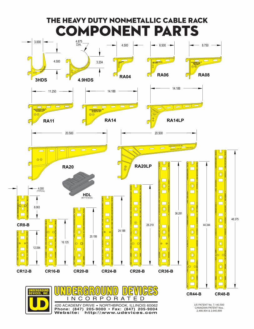
CR48-BCR44-B
CR36-BCR28-BCR24-BCR20-B
CR8-B
CR12-B
tHE hEAVY dUTY nONMETALLIC cABLE rACK
COMPONENT PARTS
CR16-B
RA043HDS
RA06
RA14
RA20 RA20LP
RA14LP
RA08
RA11
4.9HDS
DIA.
US PATENT No. 7,140,500CANADIAN PATENT Nos.
2,486,904 & 2,640,899
(TYPICAL)