Embed Size (px)
Citation preview
The Evolution of Small Hole Drilling Methods for Geotechnical
Construction Techniques
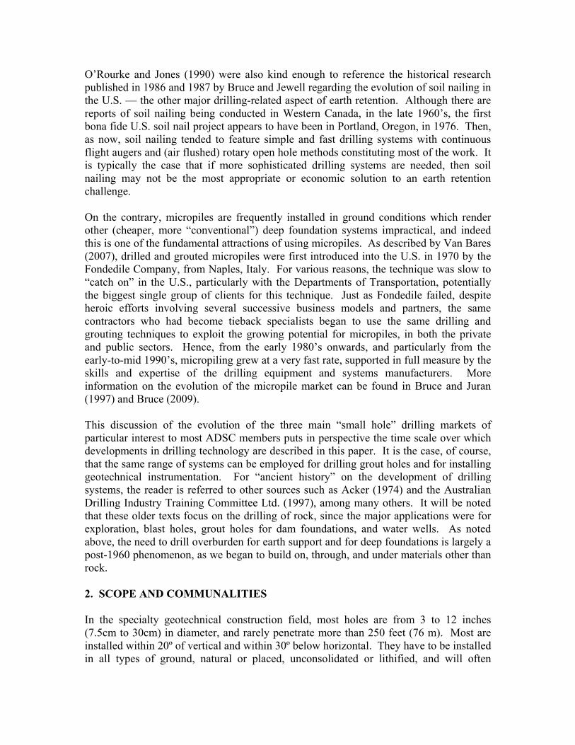
Dr. Donald A. Bruce1 ABSTRACT The evolution of small hole drilling techniques, in rock and soil, and as used in tieback, nail, and micropile construction since the early 1960’s, is described. The successive “classifications” of drilling techniques are described, as are the individual techniques which are now in common practice. Information is also provided on flushing characteristics, hole deviation, and recording of drilling progress and parameters. 1. HISTORICAL CONTEXT Writing in the seminal ASCE Conference on the Design and Performance of Earth Retaining Structures in 1990, Gould reviewed the technological developments which had taken place in that field up to 1970. The main impetus for change had come from the urban reconstruction of Europe “abetted by their fashion of emerging innovation by the constructor.” One example was the use of prestressed tieback anchors, first in rock, then in soil, and from temporary to permanent installations. The first tiebacks in rock were installed in New York City and in Milwaukee in the 1960-1961 period, and in soil in Los Angeles in 1963, although the latter were initially helical or underreamed. Hollow stem augers were well suited to the alluvials of L.A. and routinely used. European drilling developments using percussion and/or high torque rotation were used in the U.S. from the mid-1960’s. O’Rourke and Jones (1990) then picked up the story for the 1970-1990 period, noting the surge in soil anchor use associated with metro construction throughout the country and especially in the older cities of the east and west coasts. He noted “variations in drilling devices have proliferated in an attempt to cope with different soil and groundwater conditions. Bruce (1989), for example, has described at least seven different classes of overburden drilling, with modifications and special adaptations in each class.” In the subsequent 22 years, the Bruce “simple seven” classification has been progressively modified as new technologies have come to market – for example sonic drilling, and a number of concentric duplex systems – while others have dropped out or become obsolescent, e.g., the OD system.
1 President, Geosystems, L.P., P.O. Box 237, Venetia, PA 15367, U.S.A., Phone: 724-942-0570, Fax:
724-942-1911, [email protected].
O’Rourke and Jones (1990) were also kind enough to reference the historical research published in 1986 and 1987 by Bruce and Jewell regarding the evolution of soil nailing in the U.S. — the other major drilling-related aspect of earth retention. Although there are reports of soil nailing being conducted in Western Canada, in the late 1960’s, the first bona fide U.S. soil nail project appears to have been in Portland, Oregon, in 1976. Then, as now, soil nailing tended to feature simple and fast drilling systems with continuous flight augers and (air flushed) rotary open hole methods constituting most of the work. It is typically the case that if more sophisticated drilling systems are needed, then soil nailing may not be the most appropriate or economic solution to an earth retention challenge. On the contrary, micropiles are frequently installed in ground conditions which render other (cheaper, more “conventional”) deep foundation systems impractical, and indeed this is one of the fundamental attractions of using micropiles. As described by Van Bares (2007), drilled and grouted micropiles were first introduced into the U.S. in 1970 by the Fondedile Company, from Naples, Italy. For various reasons, the technique was slow to “catch on” in the U.S., particularly with the Departments of Transportation, potentially the biggest single group of clients for this technique. Just as Fondedile failed, despite heroic efforts involving several successive business models and partners, the same contractors who had become tieback specialists began to use the same drilling and grouting techniques to exploit the growing potential for micropiles, in both the private and public sectors. Hence, from the early 1980’s onwards, and particularly from the early-to-mid 1990’s, micropiling grew at a very fast rate, supported in full measure by the skills and expertise of the drilling equipment and systems manufacturers. More information on the evolution of the micropile market can be found in Bruce and Juran (1997) and Bruce (2009). This discussion of the evolution of the three main “small hole” drilling markets of particular interest to most ADSC members puts in perspective the time scale over which developments in drilling technology are described in this paper. It is the case, of course, that the same range of systems can be employed for drilling grout holes and for installing geotechnical instrumentation. For “ancient history” on the development of drilling systems, the reader is referred to other sources such as Acker (1974) and the Australian Drilling Industry Training Committee Ltd. (1997), among many others. It will be noted that these older texts focus on the drilling of rock, since the major applications were for exploration, blast holes, grout holes for dam foundations, and water wells. As noted above, the need to drill overburden for earth support and for deep foundations is largely a post-1960 phenomenon, as we began to build on, through, and under materials other than rock. 2. SCOPE AND COMMUNALITIES In the specialty geotechnical construction field, most holes are from 3 to 12 inches (7.5cm to 30cm) in diameter, and rarely penetrate more than 250 feet (76 m). Most are installed within 20º of vertical and within 30º below horizontal. They have to be installed in all types of ground, natural or placed, unconsolidated or lithified, and will often
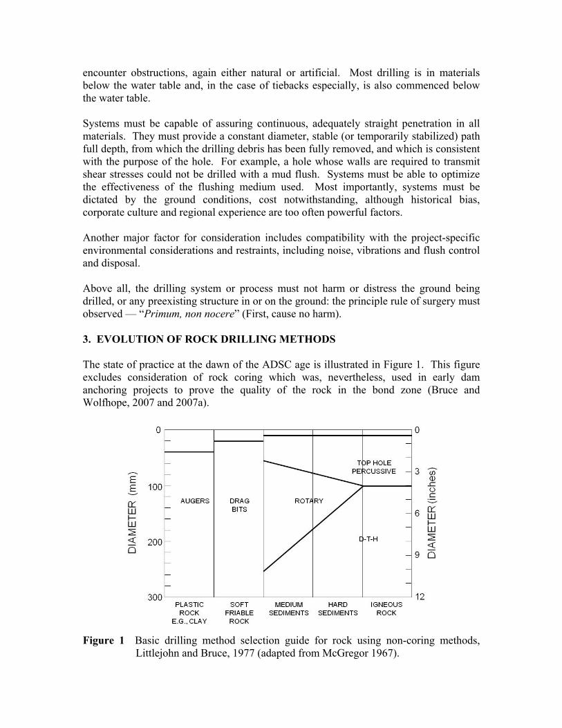
encounter obstructions, again either natural or artificial. Most drilling is in materials below the water table and, in the case of tiebacks especially, is also commenced below the water table. Systems must be capable of assuring continuous, adequately straight penetration in all materials. They must provide a constant diameter, stable (or temporarily stabilized) path full depth, from which the drilling debris has been fully removed, and which is consistent with the purpose of the hole. For example, a hole whose walls are required to transmit shear stresses could not be drilled with a mud flush. Systems must be able to optimize the effectiveness of the flushing medium used. Most importantly, systems must be dictated by the ground conditions, cost notwithstanding, although historical bias, corporate culture and regional experience are too often powerful factors. Another major factor for consideration includes compatibility with the project-specific environmental considerations and restraints, including noise, vibrations and flush control and disposal. Above all, the drilling system or process must not harm or distress the ground being drilled, or any preexisting structure in or on the ground: the principle rule of surgery must observed — “Primum, non nocere” (First, cause no harm). 3. EVOLUTION OF ROCK DRILLING METHODS The state of practice at the dawn of the ADSC age is illustrated in Figure 1. This figure excludes consideration of rock coring which was, nevertheless, used in early dam anchoring projects to prove the quality of the rock in the bond zone (Bruce and Wolfhope, 2007 and 2007a).
Figure 1 Basic drilling method selection guide for rock using non-coring methods,
Littlejohn and Bruce, 1977 (adapted from McGregor 1967).
Clearly, the generic methods were: • Rotary
– high speed, low torque (coring or “blind”) – low speed, high torque
• Percussive – top hammer – down-the-hole hammer (air flush)
A detailed discussion of these methods is provided in Weaver and Bruce (2007). Most rock drilling is now conducted with percussive drilling and, in particular, with down-the-hole drilling (DTH) for several reasons:
• DTH drilling has higher and more consistent penetration rates (by several times);
• It has lower drilling costs;
• It provides straighter holes; and
• It can provide holes of up to 40 inches (1m) in diameter to considerable depths (over 300 feet (90m)).
Several important developments have occurred with DTH drilling in the last 10 years or so in U.S. practice. These include:
• For “conventional” air-powered hammers and bits, very sophisticated computer programs and simulations are now being used to optimize performance, reliability, and durability, and to develop systems with particular characteristics, such as short hammers for restricted conditions.
• It must also be noted that the typical air pressures of 160-250 psi of the 1970’s have been replaced by pressures of up to 500 psi: penetration speeds have increased accordingly. Industrial productivities have also increased dramatically through better understandings of the metallurgy of hammers and bits, and the use of sophisticated concepts, e.g., polycrystalline diamond coatings on the carbide bit inserts.
• Reverse circulation hammers are being developed with dual wall rods. These use air and, if required, can accommodate water misting also.
• Dual fluid system (DFS) hammers feature conventional air activation, but incorporate a central tube through the hammer body that permits water to be used for hole flushing. This has not had widespread application so far in the U.S.
• Water-powered hammers have been used in the underground mining industry in Scandinavia since 1986. Within the last 10 years they have become popular and accepted as the DTH method of choice for grout hole drilling in rock (wherein air flush or “misted” flush is not permitted). They tend to satisfy the smaller end of the DTH hammer range with typical hammer diameters being 3⅛ inches (79mm), 4 inches (102mm), 4¾ inches (121mm), and 6 inches (152mm). As noted in
Section 4, these, however, can also be used in simple percussive duplex mode to install casings through overburden of 4½ to 8⅝- inch (114 to 219mm) diameter.
• Water-powered DTH hammers — the most popular versions being built by Wassara — use filtered water at pressures of up to 2,500 psi (17.2 MPa), and flow rates of 50-75 gpm (190-285 l/min) to activate the hammers and flush the hole. They are reportedly more energy efficient than conventional air-powered hammers. Interestingly, because the uphole velocity of the (water) flush is significantly lower than the corresponding velocity of air (Section 5), more stabilizers can be placed on and around the drill string, promoting a straighter hole.
• A final development for rock drilling which may be considered here is the rotary vibratory (or sonic) method, although it has so far seen most applications in overburden drilling. This technique was first researched separately in the U.S. and the USSR in the late 1940’s, and was developed commercially in the 1960’s by the oil well drilling industry. It was considered by one of its developers, Ray Roussy, “to be the only true innovation to come to the drilling industry since the Chinese invented cable tool drilling some 3,000 years ago” (Roussy, 2002). Sonic drilling uses minimal water flush volume and so is especially valuable in environmentally sensitive areas (where flush may be contaminated) and when drilling in sensitive structures such as dams (where flush must be minimized to avoid hydrofracture). The dual cased system uses high-frequency mechanical vibration to provide continuous (but disturbed) core samples or simply just to advance a temporary casing. Slow rotation is used in rock formations to even wear tendencies. It is fair to say that sonic drilling is typically commercially viable only in certain combinations of circumstances, technical and environmental. However, in the clever promotional words of its developers, it may indeed be “the wave of the future” in rock and overburden drilling technology for many applications and especially those of a remedial nature in “difficult” site and ground conditions.
4. EVOLUTION OF OVERBURDEN DRILLING METHODS 4.1 Status as at 1983 Drilling through overburden (i.e., soil and fill) can be more complex and difficult than rock drilling given the wide range of overburden properties and the influence the presence of groundwater can exert. Cost and practicality have long ruled out the use of core drilling as a viable method of drilling overburden, while the basic controls over the choice of the most appropriate system do remain:
• Cost (per lineal foot, and to mobilize/equip);
• Drill rig access restraints;
• Hole depth, diameter, and inclination;
• Flush collection and disposal concerns, noise, and vibrations;
• “End use” of the drill hole; and
• Regional preference and contractor paradigms, experience and resources. Based on his experience and observations between 1973 and 1983, Bruce (1984) first developed the simple classification of overburden drilling methods referred to by O’Rourke and Jones (1990) as also being in Bruce’s 1989 publication. Excluding “open hole,” and “foam or mud stabilized” systems, neither of which were typically feasible and/or desirable for installing anchors or nails in overburden, Bruce (1984) summarized the state of practice as follows:
1. Drive Drilling: percussive, single tube advancement, with a disposable shoe cone or cross bit to prevent soil ingress. Water flush was common. This was the simplest, cheapest and potentially fastest method in appropriate conditions (i.e., soft-to-medium, unobstructed overburden to fairly shallow depths). Casing sizes varied from 1½ to 7 inches (38 to 178mm) but the 3-inch (76mm) size seemed optimum. One serious drawback was the tendency for excessive deviations to occur, a figure of 1V in 7.5H being recorded for the 3-inch (76mm) system in one particular case. Largely due to depth and technical limitations, this method is now not widely used, although, intriguingly, the principle of pushed or jacked casing (without water flush) has been well used in the placement of long horizontal holes for compensation grouting (Heenan et al., 2003).
2. Rotary Duplex: duplex refers to the simultaneous advancement of an outer drill casing and an inner drill rod. The flushing medium is pumped down the rod and returned up the annulus in normal, “direct” circulation drilling, and through the annulus and up the rod in “reverse” circulation drilling (which is today becoming popular when dealing with difficult, highly permeable ground conditions). This method was developed by British anchor drillers in the 1960’s, and was first imported to the U.S. in the 1970’s by the forerunners of today’s anchor specialists, principally Nicholson Construction Co. and Schnabel Foundation Co. It remains the staple overburden drilling system for most anchor and micropile construction in the U.S.
3. Rotary Percussive Duplex: this method was typified by the Atlas Copco O.D. 72 system and featured simultaneous rotation, percussion, and advancement of rods and casings. In its early days, it was driven by air-powered top hammers of, therefore, limited torque and percussive capability. Its applicability was limited by depth, diameter, and ground conditions, and it only experienced somewhat of a resurgence with the arrival on the scene in the mid-1970’s of much higher powered hydraulic top hammers, such as those supplied by Krupp, Klemm, and Casagrande.
4. ODEX: restricted by hammer torque availability but faced with the increasing demand for reliable long hole production in the Scandinavian boulder clays, Atlas Copco and Sandvik jointly developed the ODEX (Overburden Drilling Eccentric) system in the early 1970’s. This percussive duplex variant uses a pilot but with an eccentric reamer to oversize the drill hole: the casing is then driven and/or rotated or pulled into the oversized hole. It reduced the torque requirement. It operates
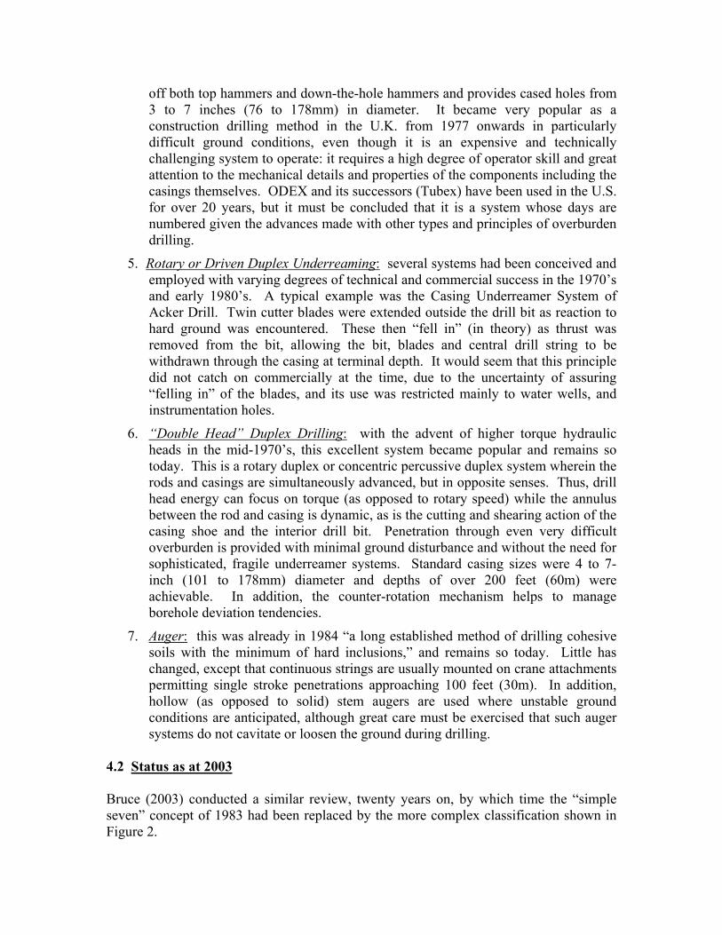
off both top hammers and down-the-hole hammers and provides cased holes from 3 to 7 inches (76 to 178mm) in diameter. It became very popular as a construction drilling method in the U.K. from 1977 onwards in particularly difficult ground conditions, even though it is an expensive and technically challenging system to operate: it requires a high degree of operator skill and great attention to the mechanical details and properties of the components including the casings themselves. ODEX and its successors (Tubex) have been used in the U.S. for over 20 years, but it must be concluded that it is a system whose days are numbered given the advances made with other types and principles of overburden drilling.
5. Rotary or Driven Duplex Underreaming: several systems had been conceived and employed with varying degrees of technical and commercial success in the 1970’s and early 1980’s. A typical example was the Casing Underreamer System of Acker Drill. Twin cutter blades were extended outside the drill bit as reaction to hard ground was encountered. These then “fell in” (in theory) as thrust was removed from the bit, allowing the bit, blades and central drill string to be withdrawn through the casing at terminal depth. It would seem that this principle did not catch on commercially at the time, due to the uncertainty of assuring “felling in” of the blades, and its use was restricted mainly to water wells, and instrumentation holes.
6. “Double Head” Duplex Drilling: with the advent of higher torque hydraulic heads in the mid-1970’s, this excellent system became popular and remains so today. This is a rotary duplex or concentric percussive duplex system wherein the rods and casings are simultaneously advanced, but in opposite senses. Thus, drill head energy can focus on torque (as opposed to rotary speed) while the annulus between the rod and casing is dynamic, as is the cutting and shearing action of the casing shoe and the interior drill bit. Penetration through even very difficult overburden is provided with minimal ground disturbance and without the need for sophisticated, fragile underreamer systems. Standard casing sizes were 4 to 7-inch (101 to 178mm) diameter and depths of over 200 feet (60m) were achievable. In addition, the counter-rotation mechanism helps to manage borehole deviation tendencies.
7. Auger: this was already in 1984 “a long established method of drilling cohesive soils with the minimum of hard inclusions,” and remains so today. Little has changed, except that continuous strings are usually mounted on crane attachments permitting single stroke penetrations approaching 100 feet (30m). In addition, hollow (as opposed to solid) stem augers are used where unstable ground conditions are anticipated, although great care must be exercised that such auger systems do not cavitate or loosen the ground during drilling.
4.2 Status as at 2003 Bruce (2003) conducted a similar review, twenty years on, by which time the “simple seven” concept of 1983 had been replaced by the more complex classification shown in Figure 2.
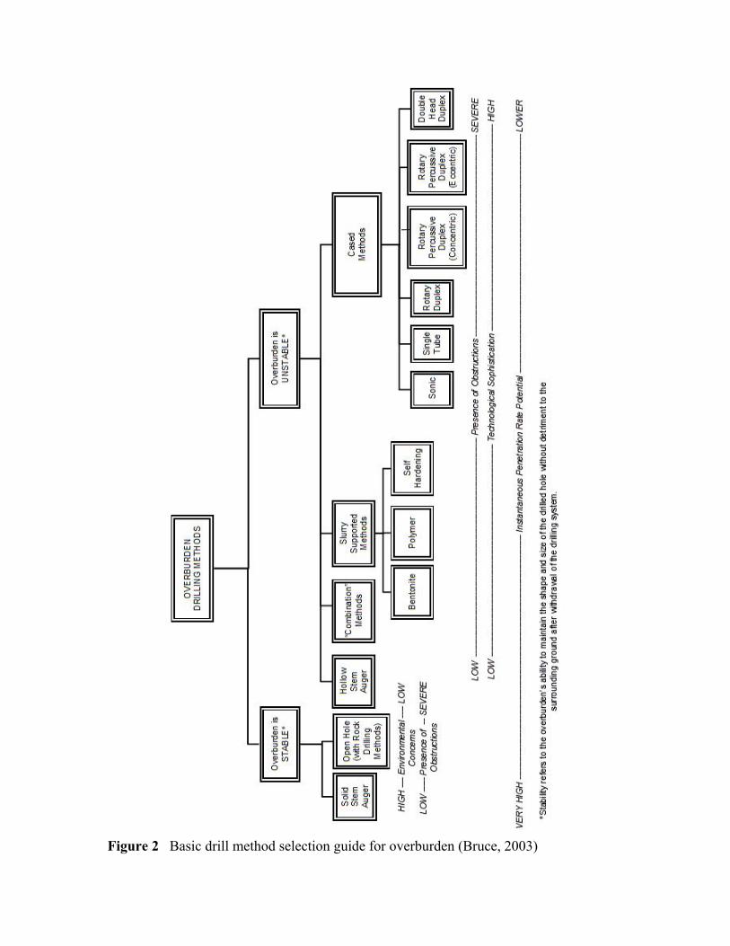
Figure 2 Basic drill method selection guide for overburden (Bruce, 2003)
Relative to the information of Section 4.1, above, the following comments are provided:
• The basic subdivision differentiates “stable” and “unstable” overburden types. The former can be penetrated by solid stem continuous flight augers or by rock drilling methods, e.g., rotary with air. Today both are in common use — ground conditions permitting!
• Most overburden is, however and naturally, unstable when drilled, and so that part of the classification dealing with methods used in such conditions is, unsurprisingly, much more heavily populated. This has become particularly relevant in more recent years when the demands placed on the drilling contractors by geotechnical engineers and geotechnical conditions have become ever more onerous: “longer holes in poorer ground.” “Unstable” overburden drilling methods are now subdivided into four categories:
(i) Hollow stem auger
(ii) “Combination” methods
(iii) Slurry supported methods
(iv) Cased methods (i) Hollow stem auger
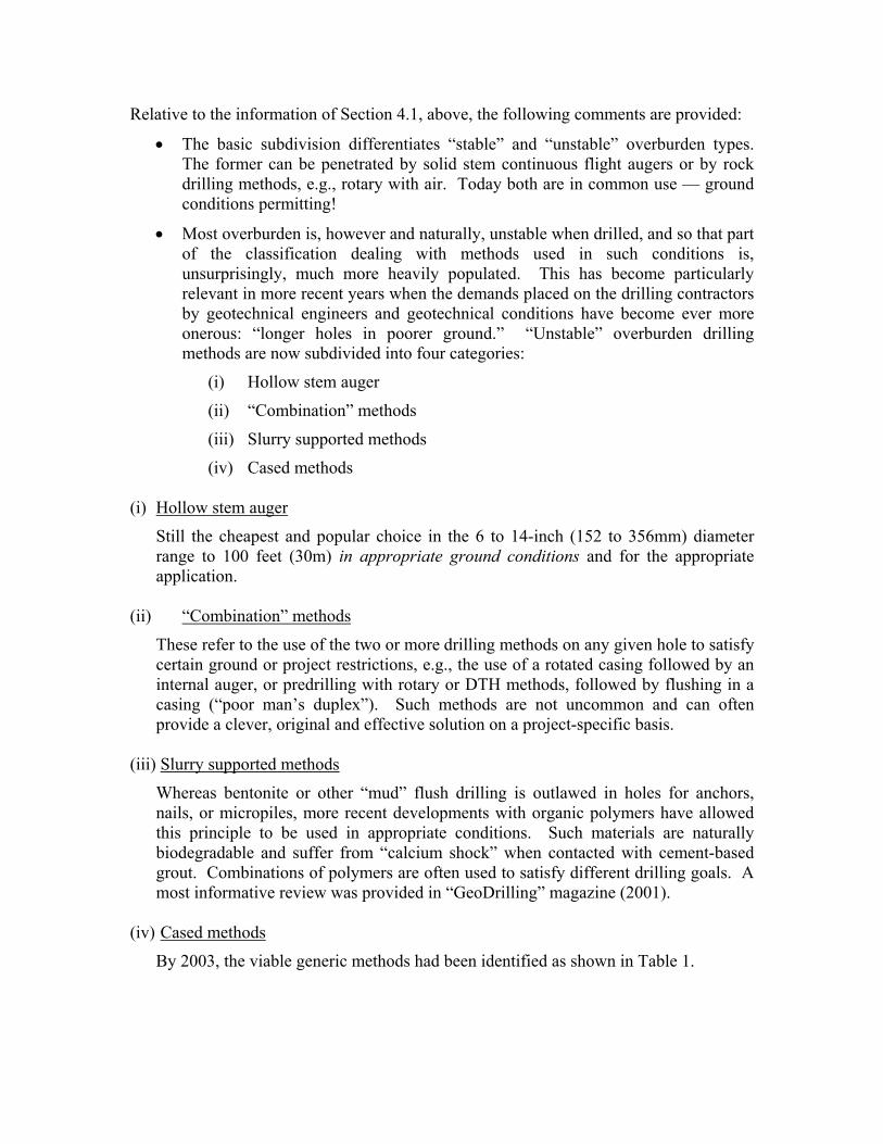
Still the cheapest and popular choice in the 6 to 14-inch (152 to 356mm) diameter range to 100 feet (30m) in appropriate ground conditions and for the appropriate application.
(ii) “Combination” methods
These refer to the use of the two or more drilling methods on any given hole to satisfy certain ground or project restrictions, e.g., the use of a rotated casing followed by an internal auger, or predrilling with rotary or DTH methods, followed by flushing in a casing (“poor man’s duplex”). Such methods are not uncommon and can often provide a clever, original and effective solution on a project-specific basis.
(iii) Slurry supported methods
Whereas bentonite or other “mud” flush drilling is outlawed in holes for anchors, nails, or micropiles, more recent developments with organic polymers have allowed this principle to be used in appropriate conditions. Such materials are naturally biodegradable and suffer from “calcium shock” when contacted with cement-based grout. Combinations of polymers are often used to satisfy different drilling goals. A most informative review was provided in “GeoDrilling” magazine (2001).
(iv) Cased methods
By 2003, the viable generic methods had been identified as shown in Table 1.
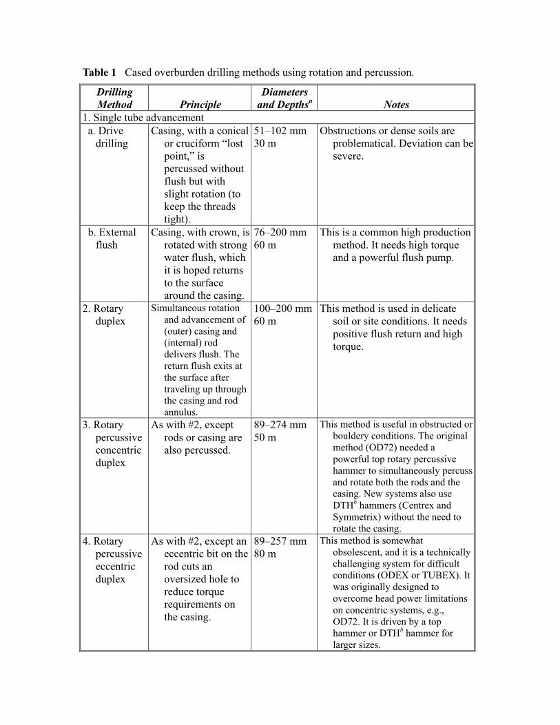
Table 1 Cased overburden drilling methods using rotation and percussion.
Drilling Method
Principle
Diameters and Depthsa
Notes
1. Single tube advancement a. Drive
drilling Casing, with a conical
or cruciform “lost point,” is percussed without flush but with slight rotation (to keep the threads tight).
51–102 mm 30 m
Obstructions or dense soils are problematical. Deviation can be severe.
b. External flush
Casing, with crown, is rotated with strong water flush, which it is hoped returns to the surface around the casing.
76–200 mm 60 m
This is a common high production method. It needs high torque and a powerful flush pump.
2. Rotary duplex
Simultaneous rotation and advancement of (outer) casing and (internal) rod delivers flush. The return flush exits at the surface after traveling up through the casing and rod annulus.
100–200 mm60 m
This method is used in delicate soil or site conditions. It needs positive flush return and high torque.
3. Rotary percussive concentric duplex
As with #2, except rods or casing are also percussed.
89–274 mm 50 m
This method is useful in obstructed or bouldery conditions. The original method (OD72) needed a powerful top rotary percussive hammer to simultaneously percuss and rotate both the rods and the casing. New systems also use DTHb hammers (Centrex and Symmetrix) without the need to rotate the casing.
4. Rotary percussive eccentric duplex
As with #2, except an eccentric bit on the rod cuts an oversized hole to reduce torque requirements on the casing.
89–257 mm 80 m
This method is somewhat obsolescent, and it is a technically challenging system for difficult conditions (ODEX or TUBEX). It was originally designed to overcome head power limitations on concentric systems, e.g., OD72. It is driven by a top hammer or DTHb hammer for larger sizes.
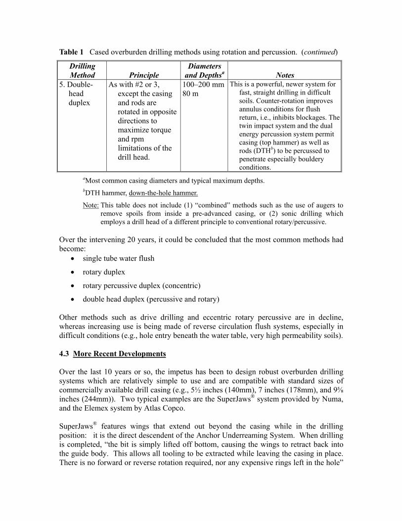
Table 1 Cased overburden drilling methods using rotation and percussion. (continued)
Drilling Method
Principle
Diameters and Depthsa
Notes
5. Double-head duplex
As with #2 or 3, except the casing and rods are rotated in opposite directions to maximize torque and rpm limitations of the drill head.
100–200 mm80 m
This is a powerful, newer system for fast, straight drilling in difficult soils. Counter-rotation improves annulus conditions for flush return, i.e., inhibits blockages. The twin impact system and the dual energy percussion system permit casing (top hammer) as well as rods (DTHb) to be percussed to penetrate especially bouldery conditions.
aMost common casing diameters and typical maximum depths. bDTH hammer, down-the-hole hammer.
Note: This table does not include (1) “combined” methods such as the use of augers to remove spoils from inside a pre-advanced casing, or (2) sonic drilling which employs a drill head of a different principle to conventional rotary/percussive.
Over the intervening 20 years, it could be concluded that the most common methods had become:
• single tube water flush
• rotary duplex
• rotary percussive duplex (concentric)
• double head duplex (percussive and rotary) Other methods such as drive drilling and eccentric rotary percussive are in decline, whereas increasing use is being made of reverse circulation flush systems, especially in difficult conditions (e.g., hole entry beneath the water table, very high permeability soils). 4.3 More Recent Developments Over the last 10 years or so, the impetus has been to design robust overburden drilling systems which are relatively simple to use and are compatible with standard sizes of commercially available drill casing (e.g., 5½ inches (140mm), 7 inches (178mm), and 9⅝ inches (244mm)). Two typical examples are the SuperJaws® system provided by Numa, and the Elemex system by Atlas Copco. SuperJaws® features wings that extend out beyond the casing while in the drilling position: it is the direct descendent of the Anchor Underreaming System. When drilling is completed, “the bit is simply lifted off bottom, causing the wings to retract back into the guide body. This allows all tooling to be extracted while leaving the casing in place. There is no forward or reverse rotation required, nor any expensive rings left in the hole”
(Numa Website, 2012). It is promoted in 2 versions. One uses an inexpensive drive shoe, welded to the front of the casing. As the bit advances through the formation, the casing is advanced at the same rate due to the drive shoulder on the guide body contacting the drive shoe welded to the casing. The second version ― “SuperJaws® ND” ― uses thick wall casing or thick wall threaded casing. The guide body has no drive shoulder and the casing is advanced via a casing hammer, duplex diverter, or dual rotary system. This version is often used in micropile and tieback work where the casing is to be recovered, or in deep overburden areas where high amounts of friction build up around the casing. This system is used for drilling holes 5½ (140mm) to 42 inches (106.7cm) in diameter, and is provided in 2-, 3- and 4-wing configurations, depending on diameter. Atlas Copco claim their Elemex system (Atlas Copco Website, 2012) was designed to meet the environmental challenges of using compressed air in urban locations, as well as optimizing drill bit performance. It minimizes air escape to the surrounding ground as the high pressure air (used in the DTH) never faces the ground directly, but is redirected. The air is blown from the bit face against an extended ring bit (mounted on the casing), causing the redirection, while maintaining the cleaning action. The ring bit closes the drilling area and keeps the air in the flushing grooves. This ring bit also prolongs the life of the pilot bit. This is a simple and reliable system to operate (hence the name) and is claimed to drill faster and straighter holes than when “drilling with an old type of underreaming system.” On the other hand, a “new type” of underreaming system is in the later stages of prototype development by Center Rock Inc. (Website, 2012). This features a patented method of extending and retracting cutting wings on the central pilot bit in a very simple and reliable fashion. Unlike other underreamed systems, the wings, when extended are locked out mechanically, do not rely on downward pressure. They therefore prevent the outer casing from accidentally slipping off. The system, named Rotoloc, does not need a drive shoe, leaves nothing sacrificial in the ground, and fits casings of standard sizes 5½ to 9⅝-inch (140 to 244mm) diameter. 5. ANCILLARY DEVELOPMENTS Concomitant with drilling system development, there has been steady progress in drill rig design, especially in the areas of power, stability, maneuverability and ease of operation. Also, as noted above, compressors have upgraded, as have water flush pump capacities. However, there have been noticeable developments over the years in activities ancillary to small hole drilling. 5.1 Appreciation of the Significance of Circulation (Flush) Type and Application Industry has long been aware of the respective merits and dangers of air and water flush, especially in urban and karstic environments. The Uphole Velocity (UHV) of the circulation medium must exceed the “sinking velocity” of the cuttings (Kutzner, 1996). In water, for example, this sinking velocity, , of spherical particles of diameter is: 10 in m s⁄
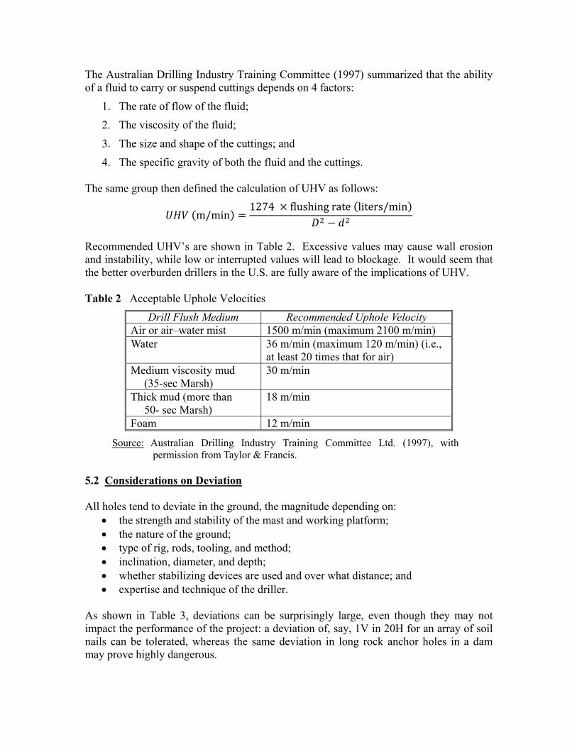
The Australian Drilling Industry Training Committee (1997) summarized that the ability of a fluid to carry or suspend cuttings depends on 4 factors:
1. The rate of flow of the fluid;
2. The viscosity of the fluid;
3. The size and shape of the cuttings; and
4. The specific gravity of both the fluid and the cuttings. The same group then defined the calculation of UHV as follows: m/min 1274 flushing rate liters/min
Recommended UHV’s are shown in Table 2. Excessive values may cause wall erosion and instability, while low or interrupted values will lead to blockage. It would seem that the better overburden drillers in the U.S. are fully aware of the implications of UHV. Table 2 Acceptable Uphole Velocities
Drill Flush Medium Recommended Uphole Velocity Air or air–water mist 1500 m/min (maximum 2100 m/min) Water 36 m/min (maximum 120 m/min) (i.e.,
at least 20 times that for air) Medium viscosity mud
(35-sec Marsh) 30 m/min
Thick mud (more than 50- sec Marsh)
18 m/min
Foam 12 m/min
Source: Australian Drilling Industry Training Committee Ltd. (1997), with permission from Taylor & Francis.
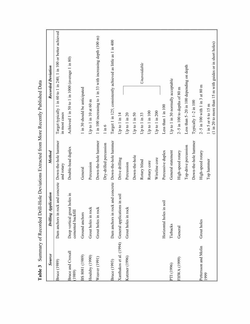
5.2 Considerations on Deviation All holes tend to deviate in the ground, the magnitude depending on:
• the strength and stability of the mast and working platform; • the nature of the ground; • type of rig, rods, tooling, and method; • inclination, diameter, and depth; • whether stabilizing devices are used and over what distance; and • expertise and technique of the driller.
As shown in Table 3, deviations can be surprisingly large, even though they may not impact the performance of the project: a deviation of, say, 1V in 20H for an array of soil nails can be tolerated, whereas the same deviation in long rock anchor holes in a dam may prove highly dangerous.
Tab
le 3
Su
mm
ary
of R
ecor
ded
Dril
l-Hol
e D
evia
tions
Ext
ract
ed fr
om M
ore
Rec
ently
Pub
lishe
d D
ata
Reco
rded
Dev
iatio
n
Targ
et ty
pica
lly 1
in 6
0 to
1 in
240
; 1 in
100
or b
ette
r ach
ieve
d in
mos
t cas
es
Ach
ieve
d 1
in 5
0 to
1 in
100
0 (a
vera
ge 1
in 8
0)
1 in
30
shou
ld b
e an
ticip
ate d
Up
to 1
in 1
0 at
60
m
1 in
100
incr
easi
ng to
1 in
33
with
incr
easi
ng d
epth
(100
m)
1 in
6
Targ
et 1
in 1
25; c
onsi
sten
tly a
chie
ved
as li
ttle
as 1
in 4
00
Up
to 1
in 1
4
Una
void
able
Less
than
1 in
100
Up
to 1
in 3
0 no
rmal
ly a
ccep
tabl
e
2–5
in 1
00 to
dep
ths o
f 80
m
Less
than
5–2
0 in
100
dep
endi
ng o
n de
pth
Typi
cally
1–2
in 1
00
2–5
in 1
00 w
ith 1
in 3
at 8
0 m
1 in
5 o
r 6 to
15
m
(1 in
20
to m
ore
than
15
m w
ith g
uide
s or i
n sh
ort h
oles
)
Up
to 1
in 2
0
Up
to 1
in 5
0
Up
to 1
in 3
3
Up
to 1
in 1
00
Up
to 1
in 2
00
Met
hod
Dow
n-th
e-ho
le h
amm
er
and
rota
ry
Dou
ble-
head
dup
lex
Gen
eral
Perc
ussi
on
Dow
n-th
e-ho
le h
amm
er
Dry
-dril
led
perc
ussi
on
Dow
n-th
e-ho
le h
amm
er
Driv
e dr
illin
g
Perc
ussi
on
Dow
n-th
e-ho
le
Rot
ary
blin
d
Rot
ary
core
Wire
line
core
Perc
ussi
ve d
uple
x
Gen
eral
stat
emen
t
Hig
h-sp
eed
rota
ry
Top-
driv
e pe
rcus
sion
Dow
n-th
e-ho
le h
amm
er
Hig
h-sp
eed
rota
ry
Top
ham
me r
Dril
ling
Appl
icat
ion
Dam
anc
hors
in ro
ck a
nd c
oncr
ete
Dee
p ve
rtica
l gro
ut h
oles
in
cem
ente
d ba
ckfil
l
Gro
und
anch
ors
Gro
ut h
oles
in ro
c k
Gro
ut h
oles
in ro
c k
Dam
anc
hors
in ro
ck a
nd c
oncr
ete
Gen
eral
app
licat
ions
in so
il
Gro
ut h
oles
in ro
c k
Hor
izon
tal h
oles
in so
il
Tieb
acks
Gen
eral
Gro
ut h
oles
Sour
ce
Bru
ce (1
989)
Bru
ce a
nd C
roxa
ll
(198
9)
BS
8081
(198
9)
Hou
lsby
(199
0)
Wea
ver (
1991
)
Bru
ce (1
993)
Xan
thak
os e
t al.
(199
4)
Kut
zner
(199
6)
PTI (
1996
)
FHW
A (1
999)
Pette
rsso
n an
d M
olin
19
99
Two points are noteworthy. Firstly, deviation is not usually important, and so is not frequently measured. However, if it is important (e.g., on long micropiles or long horizontal compensation grouting holes), then there are very efficient and very accurate means of measuring them. Weaver and Bruce (2007) provide guidance. 5.3 Recording of Drilling Progress and Parameters Now commonly referred to as “Measurement While Drilling” (MWD), this embraces the concept that every hole drilled, regardless of purpose, is a valuable source of knowledge of the ground. Thus, we no longer rely on a limited number of site investigation holes to categorize the ground, but, instead, common practice has devolved towards “squeezing out” as much information as possible on the progress of each production hole also. When and if conducted in the years before 1985, MWD was a manual process whereby the driller, superintendent, inspector, or geologist maintained simple, handwritten logs. Unfortunately, such logs were rarely recorded on standard forms, instead, at best, on the “driller’s book,” or, at worst, on the notepad from the particular hotel du Jour. ADSC has done wonders these last few years to develop and encourage the use of standardized reporting. In addition to recording all the standard drilling observations (e.g., speed, flush return, stability, etc.), it is essential that the “exceptions and unexpecteds” are recorded (Weaver, 1991). If properly conducted, even manual MWD can provide a windfall of data, for the benefit of all parties. Automated MWD began in France in the early 1970’s, and began to be used (principally on jet grouting projects) in the U.S. about 20 years later. It has developed in spurts, associated with particular advances in computer software and hardware. The fundamental English-language paper was that of DePaoli et al. (1987) who defined the concept of drilling specific energy, , as: ⁄ 2 ⁄
where is specific energy (kJ/m3), is thrust (kN), is the cross-sectional area of the hole (m2), is rotational speed (revolutions per second), is torque (kN – m), and is the penetration rate (m/s). The main parameters which are recorded are:
• penetration rate • thrust, or hold-back • torque • rotational speed • reflected energy (in percussion drilling) • drill flush pressure • drill flush gain or loss
Contemporary systems provide a real time record of all these parameters and can transmit and process the data for specific technical, management, or contractual purposes. In summary, the use of automated MWD can significantly enhance the effectiveness and efficacy of the inspection staff, provide more reliable and complete data for documentation and evaluation, and increase the likelihood that the work is being
conducted in an acceptable, appropriate, and cost-effective manner. Even then, supplementation of this data with manual observations remains an excellent idea. As in the case for each of the drilling systems referred to in other sections, much valuable information can be gleaned from the websites of the respective suppliers and manufacturers. 6. FINAL REMARKS A driller from the 1960’s suddenly teleported into the Year of Our Lord 2012 would be in a state of severe shock, probably awe, and considerable disorientation if he were to visit a typical contemporary drilling site. Drill rigs would be huge and powerful ― relatively quiet and surprisingly “user-friendly.” Drilling systems would be diverse and, depending on the experience of our 1960’s man, either indescribably complex or astonishingly and intuitively easy. His every work step would be electronically monitored ― comforting to the honest and competent man, extremely worrisome for the others. There would be the realization that all sites do not have to have at least knee-deep mud for any self-respecting driller to be regarded as a “real man.” And, above all, and with a dawning sense of relief, he would come to realize that drilling sites were no longer the indiscriminate killing grounds of his uncles, father, and grandfather in the desperate pre-War Years. For the last reason alone, we should be grateful for the technological advances which have abounded in the 50 years since our small hole drilling business saw commercial light. REFERENCES Acker W.L. (1974). “Basic Procedures for Soil Sampling and Core Drilling,” Distributed
by Acker Drill Co. Svc., 246 pp.
Atlas Copco Website. (2012). http://www.atlascopco.com/elemex/
Australian Drilling Industry Training Committee Ltd. (1997). Drilling: The Manual of Method, Applications, and Management. CRC Press LLC., Boca Raton, Florida.
Bruce, D.A. (1984). “The Drilling and Treatment of Overburden.” Geodrilling, August and October, 11 p. (First presented at Drillex 84 Conference, Stoneleigh, Warwickshire, April, 1984.)Bruce (1989)
Bruce, D.A. (1989). “Contemporary Practice in Geotechnical Drilling and Grouting.” Keynote Lecture, First Canadian International Grouting Seminar, Toronto, April 18, 28 p.
Bruce, D.A. (2003). “The Basics of Drilling for Specialty Geotechnical Construction Processes.” Grouting and Ground Treatment, Proceedings of the Third International Conference, Geotechnical Special Publication No. 120. Edited by L.F. Johnsen, D.A. Bruce, and M.J. Byle, American Society of Civil Engineers, New Orleans, LA, February 10-12, pp. 752-771.
Bruce, D.A. (2009). “Micropiles in Middle Age: Triumphs, Failures and Challenges,” 5th Lizzi Lecture, International Workshop on Micropiles,, International Society for Micropiles, Presentation on CD, London, U.K, May, 16 p.
Bruce, D.A. and I. Juran. (1997). “Drilled and Grouted Micropiles: State of Practice Review, Volumes I, II, III, and IV.” Prepared for the Federal Highway Administration, Publication Nos. FHWA-RD-96-016. –017, -018, and –019, July.GeoDrilling Magazine 2001
Bruce, D.A. and R.A. Jewell. (1986, 1987). “Soil Nailing: Application and Practice.” Ground Engineering 19 (8) pp. 10-15, and 20 (1) pp. 21-38.
Bruce, D.A., and J. Wolfhope (2007). “Rock Anchors for North American Dams: The National Research Program Bibliography and Database,” Institution of Civil Engineers, Ground Anchorages and Anchored Structures in Service, November 26-27, London, England, U.K., 11 p.
Bruce, D.A., and J. Wolfhope (2007a). “Rock Anchors for North American Dams: The Development of the National Recommendations (1974-2004),” Institution of Civil Engineers, Ground Anchorages and Anchored Structures in Service, November 26-27, London, England, U.K., 11 p.
Center Rock Inc. (2012). http://www.centerrock.com.
De Paoli, B., Viola, G., and Tomiolo, A. (1987). “The Use of Drilling Energy for Soil Classification,” Second International Symposium, FMGM87 , Kobe, Japan, April 6–9.
GeoDrilling Int. (2001b). “Drilling Fluids and Additives.” GeoDrilling Int. 9(9), November, 4–16.
Gould, J.P. (1990). “Earth Retaining Structures – Developments Through 1970,” Proceedings of Conference: Design and Performance of Earth Retaining Structures, ASCE Geotechnical Special Publication No. 25, Cornell University, Ithaca, NY, June 18-21, pp. 8-21.
Heenan, D.M., J.W. Vataja, and T.L. Dreese. (2003). “Frac Grouting – A Case History,” Grouting and Ground Treatment, Proceedings of the Third International Conference, Geotechnical Special Publication No. 120. Edited by L.F. Johnsen, D.A. Bruce, and M.J. Byle, American Society of Civil Engineers, New Orleans, LA, February 10-12, pp. 824-836.
Houlsby, A.C. (1990). Construction and Design of Cement Grouting. John Wiley & Sons, 442 p.
Kutzner, C. (1996). Grouting of Rock and Soil. A.A. Balkema, Rotterdam, 271 p.
Littlejohn, G.S. and D.A. Bruce. (1977). “Rock Anchors - State of the Art.” Foundation Publications, Essex, England, 50 p. (Previously published in Ground Engineering in 5 parts, 1975-1976.)
Numa Website. (2012). http://www.numahammers.com
O’Rourke, T.D. and C.J.F.P. Jones. (1990). “Overview of Earth Retention Systems: 1970-1990,” Proceedings of Conference: Design and Performance of Earth Retaining Structures, ASCE Geotechnical Special Publication No. 25, Cornell University, Ithaca, NY, June 18-21, pp. 22-51.
Roussy, R. (2002). “The Development of Sonic Drilling Technology.” GeoDrilling Int. 10(10), December, 12–14.
Van Bares, F.A. (2007). “Root Piles in the USA - Fondedile S.P.A. and Fondedile Corp.: A Chronicle,” International Workshop on Micropiles, Toronto, ON, Canada, International Society for Micropiles, on CD, 26 p.
Weaver, K.D. (1991). Dam Foundation Grouting. American Society of Civil Engineers, New York, NY, 178 p.
Weaver, K.D. and D.A. Bruce (2007). “Dam Foundation Grouting, Revised and Expanded Edition,” American Society of Civil Engineers, ASCE Press, New York, 504 p.