Embed Size (px)
Citation preview
NASA Technical Memorandum 86038 NASA-TM-8603819860005880
Stress Concentration Around a Small (~ircular Hole in the HiMAT (:omposite Plate William L. Ko
December 1985
National Aeronautics and Space Administration
VIRGINIA
1111111111111 1111 11111111111'1111"'1 11111111 NF00875

NASA Technical Memorandum 86038
tress Concentration Around a Small (~ircular Hole in the HiMAT
omposite Plate William L. Ko Ames Research Center, Dryden Flight Research Facility, Edwards, California
1985
National Aeronautics and Space Administration Ames Research Center Dryden Flight Research Facility Edwards, California 93523
SUMMARY
Anisotropic plate theory was used to calculate the anisotropic stress concentra-1:ion factors for a composite plate (AS/3501-5 graphite/epoxy composite, single ply or laminated) containing a circular hole. This composite material was used on the highly maneuverable aircraft technology (HiMAT) vehicle. It was found that the anisotropic stress concentration factor could be greater or less than 3 (the stress concentration factor for isotropic materials), and that the locations of the maximum 1:angential stress points could shift with the change of fiber orientation with respect to the loading axis. The effect of hole size on the stress concentration factor was examined using the point Stress Criterion and the Averaged Stress Criterion. The predicted stress concentration factors based on the two theories compared fairly well with the measured values for the hole size 0.3175 cm (1/8 in). It was also found that through the lamination process, the stress concentration factor could be reduced drastically, indicating an improvement in structural performance.
INTRODUCTION
When an infinite isotropic plate containing a circular hole is subjected to remote uniaxial tension, the tangential stress along the boundary of the circular hole will reach a value three times the remote tensile stress at two boundary points lying on the hole diameter perpendicular to the loading axis. Namely, the maximum tangential stress concentration factor is 3, which is independent of the hole size. F'or anisotropic materials, such as fiber-reinforced composite materials, the picture is entirely different. The value of the maximum tangential stress concentration factor for a composite plate can be greater or less than 3, and the locations of the maximum s·tress points could shift depending on the loading direction and the fiber orientations.
This report calculates the tangential stress distribution around a circular hole in a composite plate (single ply or laminated) and examines how the maximum stress points shift with the fiber orientations. In addtion, the dependency of the stress concentration factor on the hole size is examined. In the analysis, the composite system is treated as a continuous anisotropic plate having effective elastic properties. The calculated stress concentration factors are then compared with experimental data.
NOMENCLATURE
small fixed distance ahead of the hole boundary used in the Average. Stress Criterion
characteristic distance ahead of the hole boundary used in the Point Stress Criterion
modulus of elasticity of single ply in axis-l direction or modulus of elasticity of anisotropic plate in axis-l direction
E2
-E2
K
k
L
N
R
x,y
T
{1 ,2}
ex
El
111 I 112
2
modulus of elasticity of single ply in axis-2 direction or modulus of elasticity of anisotropic plate in axis-2 direction
modulus of elasticity of laminated composite plate in axis-1 direction
modulus of elasticity of laminated composite plate in axis-2 direction
modulus of elasticity of anisotropic plate in ex direction
modulus of elasticity of single ply in fiber direction
modulus of elasticity of single ply transverse to fiber direction
shear modulus of single ply associated with {1 , 2} system
shear modulus of single ply associated with {L,T} system
stress concentration factor
stress concentration factor at ex = ~/2
=~ coordinate axis in fiber direction
number of composite layers
radius of circular hole
rectangular Cartesian coordinates
coordinate axis transverse to fiber direction
rectangular coordinate system
angular cooordinate
angle between axis 1 and axis L
complex roots of the anisotropic plate characteristic equation
Poisson's ratios of single ply with respect to {1 , 2} system
Poisson's ratio of single ply with respect to {L,T} system
Poisson's ratios of laminated composite plate with respect to {1 , 2} system
R/(R + do>
£;2
stress in a direction
tensile strength of composite plate
(j remote tensile stress 00
stress in y direction
COMPOSITE ELASTIC CONSTANTS
Let axes {1,2} be the coordinate axes, and let axes {L,T} be the principal elastic or material axes of the single composite ply shown in figure 1. The plyelastic constants {E1, E2' G12' V12' V21} with respect to the {1,2} system can be
related to the material constants {EL' ET , ~T' VLT' ~L} with respect to the {L,T} system through the following equations (refs. 1 and 2).
EL/[COS4 EL
sin4 e + 1 (EL 2VLT) sin2
2eJ E1 e +-4 GLT ET
( 1 )
E2 = EL/[sin4 e +
EL cos4 e + 1 (EL 2VLT) sin2
2eJ ET 4 GLT (2 )
G12 EL /[1 + 2vLT EL
(1 + 2 Vr..T EL EL) cos2
2eJ +- + ET ET GLT
(3 )
v12 E1[ EL vLT l(1 + 2 Vr..T +
EL EL ) sin2 2eJ ET GLT
(4 )
v21 E2 [ 1 ( EL
EL ) sin2 2eJ EL vLT - 4" 1 + 2 VLT + ET GLT
(5 )
If the composite plate is made of N number of single plies with different fiber
orientations, then by using the mixture rule, the engineering elastic constants {E1'
E2' G12' V12' V21} for the composite plate can be written as
N
E1 = L E1 ( e· ) (6) N j=1 J
N
E2 N L E2 ( e· ) (7 ) j=1 J
3
N - 1 L (ej) G12 = - G12 N j=1 (8 )
N
v12 =i ,LV12 (e, ) )=1 )
(9)*
N 1 .L v21 (e, ) v21 = -N )=1 ) ( 1 0 ) *
The HiMAT composite plate (A5/3501-5 graphite/epoxy composite) is made up of 34 plies (N = 34, ply thickness = 0.0133 cm (0.00525 in» with the following fiber orientations:
14 plies of e +50° fiber orientation
14 plies of e = -50° fiber orientation
6 plies of e +35° fiber orientation
The ply engineering elastic constants with respect to the principal elastic axes {L,T} are given by
EL = 137.90 GPa (20 x 106 lb/in2 )
ET = 10.27 GPa ( 1.49 x 10⁶ lb/in2 )
GLT = 2.41 GPa (0.35 x 10⁶ lb/in2 )
vLT = 0.3
( 11)
(12 )
( 13 )
(14)
using equations (11) to (14), the ply elastic constants with respect to axes {1,2} can be calculated from equations (1) to (5). For e = ±50° fiber orientations,
E1(±500) = 7.45 GPa (1.0809 x 10⁶ lb/in2 ) ( 15 )
E2(±500) = 8.43 GPa (1.2237 x 10⁶ lb/in2 ) (16)
G12(±50) = 8.46 GPa (1.2274 x 10⁶ lb/in2 ) ( 17 )
V12(±50) = 0.5676 ( 18 )
For e = +35° fiber orientation,
E1(+35°) = 9.59 GPa (1.3904 x 10⁶ lb/in2 ) (19)
E2(+35°) ~·7.40 GPa (1.0732 x 10⁶ lb/in2 ) (20)
G12(+35°) = 6.91 GPa (1.0025 x 10⁶ lb/in2 ) (21)
- -*Note that the mixture rule does not give the relationship v12E2 = v21 E1.
4
0.6671 (22 )
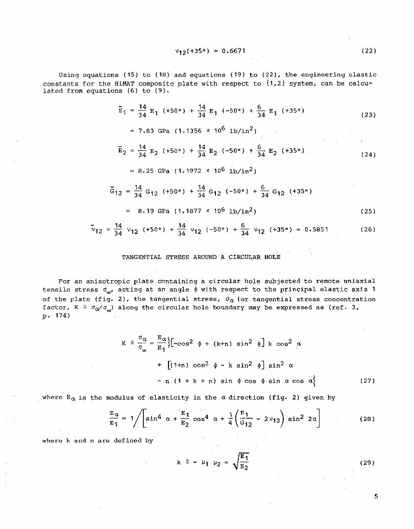
Using equations (15) to (18) and equations (19) to (22), the engineering elastic constants for the HiMAT composite plate with respect to {1,2} system, can be calculated from equations (6) to (9).
(23)
7.83 GPa (1.1356 x 10⁶ lb/in2 )
(24)
8.25 GPa (1.1972 x 10⁶ Ib/in2 )
8.19 GPa (1.1877 x 10⁶ Ib/in2 ) (25)
0.5851 (26)
TANGENTIAL STRESS AROUND A CIRCULAR HOLE
For an anisotropic plate containing a circular hole subjected to remote uniaxial tensile stress °
00, acting at an angle ~ with respect to the principal elastic axis 1
of the plate (fig. 2), the tangential stress, 0a (or tangential stress concentration factor, K = oa/0oo) along the circular hole boundary may be expressed as (ref. 3, p. 174)
K -
+ [( Hn) cos2 ~ - k sin2 ~] sin2 a
- n (1 + k + n) sin ~ cos ~ sin a cos a~ (27)
where Ea is the modulus of elasticity in the a direction (fig. 2) given by
(28)
where k and n are defined by
(29)
5
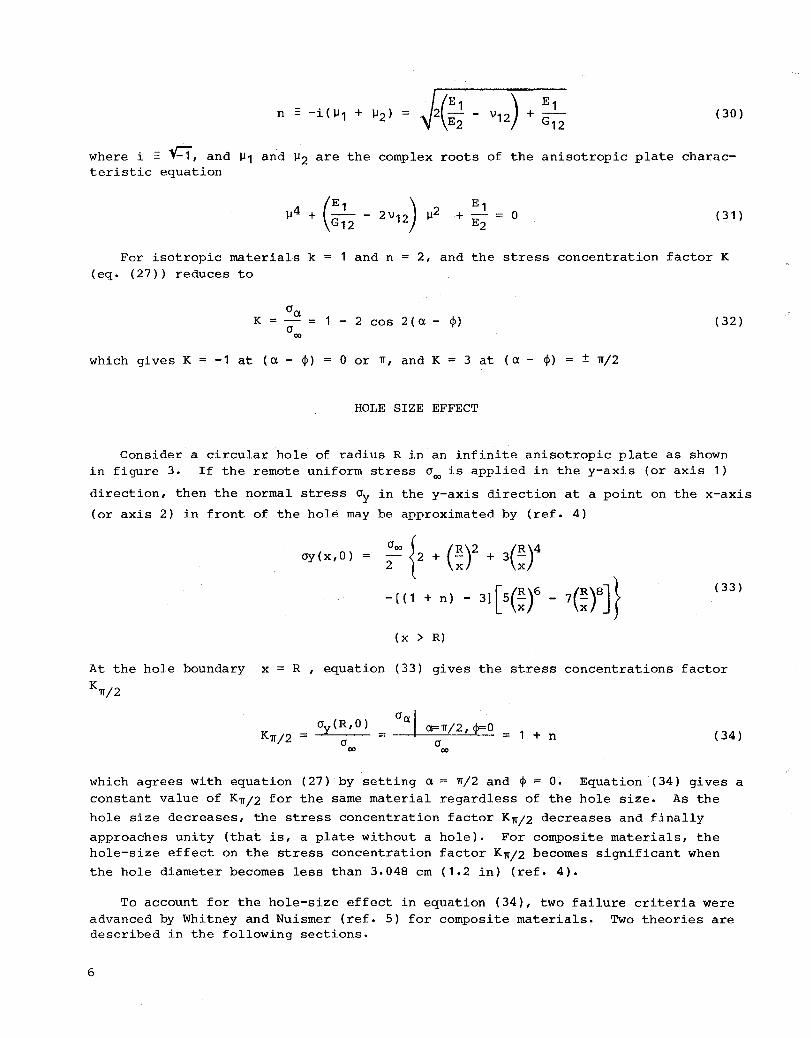
(30)
where i = ~, and ~1 and ~2 are the complex roots of the anisotropic plate characteristic equation
o (31 )
For isotropic materials k (eq. (27» reduces to
1 and n 2, and the stress concentration factor K
K 1 - 2 cos 2 (a - <1» (32)
which gives K = -1 at (a - <1» = 0 or n, and K 3 at (a- <1» ± n/2
HOLE SIZE EFFECT
Consider a circular hole of radius R in an infinite anisotropic plate as shown in figure 3. If the remote uniform stress croo is applied in the y-axis (or axis 1)
direction, then the normal stress cry in the y-axis direction at a point on the x-axis
(or axis 2) in front of the hole may be approximated by (ref. 4)
cry(x,O)
(33)
(x > R)
At the hole boundary x = R , equation (33) gives the stress concentrations factor
Kn/2
Kn/2 cr 00
a=n/2, <1>=0 cr
00
1 + n (34)
which agrees with equation (27) by setting a n/2 and <I> = O. Equation (34) gives a constant value of Kn/2 for the same material regardless of the hole size. As the
hole size decreases, the stress concentration factor Kn/2 decreases and finally
approaches unity (that is, a plate without a hole). For composite materials, the hole-size effect on the stress concentration factor Kn/2 becomes significant when
the hole diameter becomes less than 3.048 cm (1.2 in) (ref. 4).
To account for the hole-size effect in equation (34), two failure criteria were advanced by Whitney and Nuismer (ref. 5) for composite materials. Two theories are described in the following sections.
6
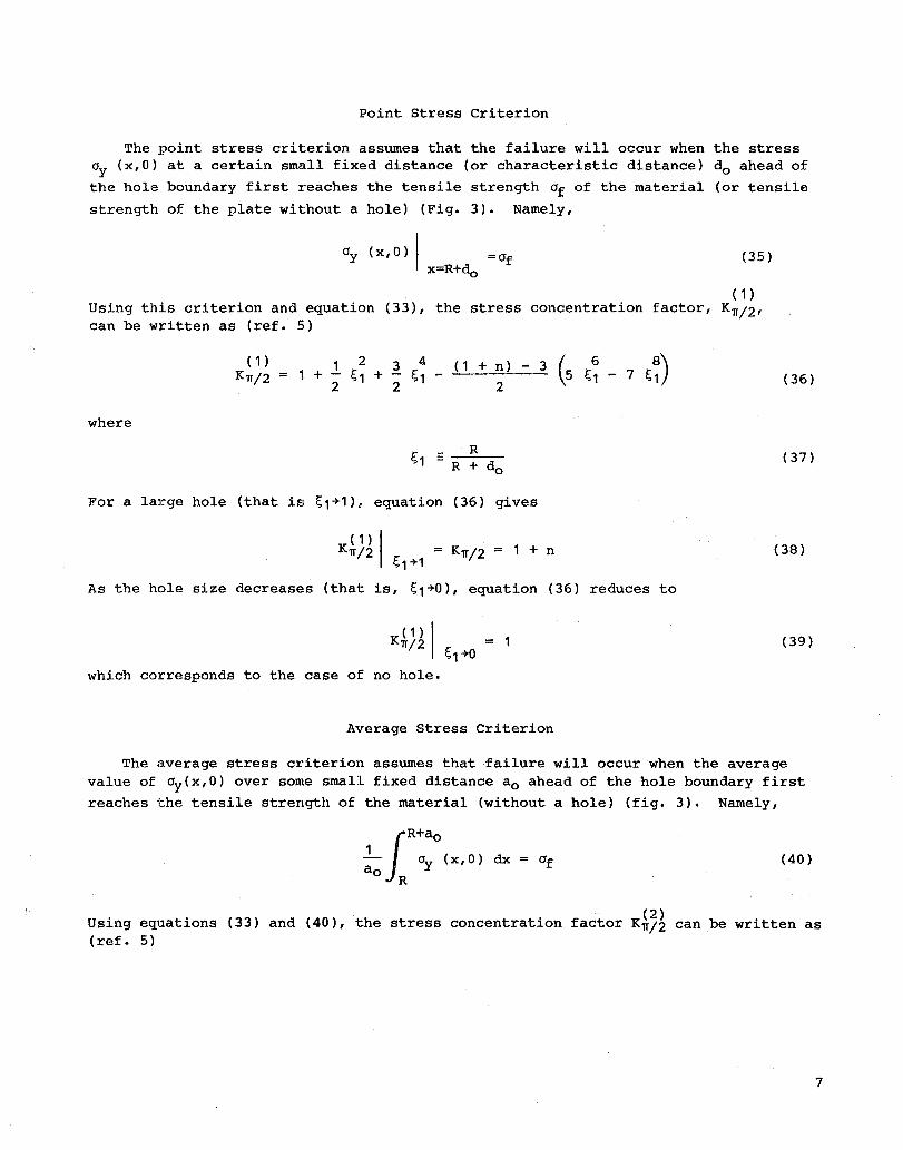
Point Stress Criterion
The point stress criterion assumes that the failure will occur when the stress 0y (x,O) at a certain small fixed distance (or characteristic distance) do ahead of
the hole boundary first reaches the tensile strength of of the material (or tensile
strength of the plate without a hole) (Fig. 3). Namely,
0y ( x , 0) I = of x=R+do
(35)
( 1 ) Using this criterion and equation (33), the stress concentration factor, Kn/2' can be written as (ref. 5)
where
(1)
Kn/2 1 2 3 4 (1 + n) - 3 (6 8)
1 + ~1 + ~1 - """-'--=.!--"::" 5 ~1 - 7 ~1 222
For a large hole (that is ~1+1), equation (36) gives
( 1) I Kn/2 = Kn/2 = 1 + n ~1 +1
As the hole size decreases (that is, ~1+0), equation (36) reduces to
K (/1) I n 2 r: '-1+0
1
which corresponds to the case of no hole.
Average Stress Criterion
(36)
(37)
(38)
(39)
The average stress criterion assumes that failure will occur when the average value of 0y(x,O) over some small fixed distance ao ahead of the hole boundary first
reaches the tensile strength of the material (without a hole) (fig. 3). Namely,
(40)
Using equations (33) and (40), the stress concentration factor K~7~ can be written as (ref. 5)
7
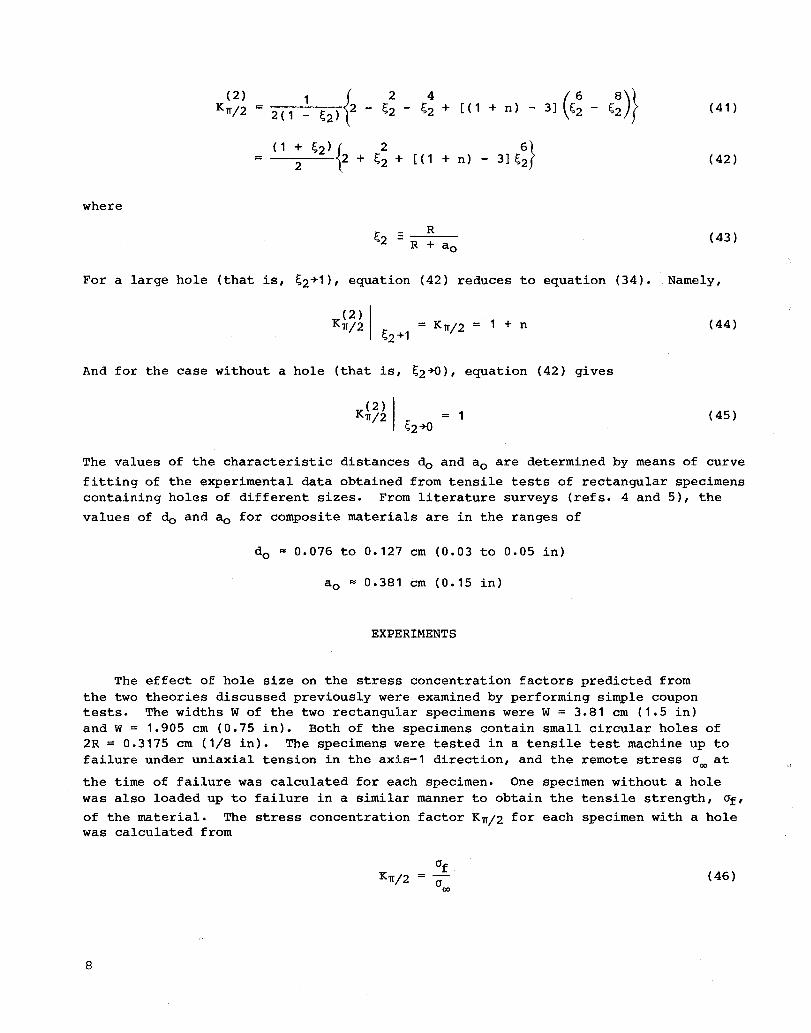
where
(2) K1f/2 2(1 ~ ~2){2 - ~~ - ~~ + [(1 + n) - 3] (~~ - ~~)}
(1 + ~2) {2 6} = 2 2 + ~2 + [( 1 + n) - 3] ~2
(41)
(42)
(43)
For a large hole (that is, ~2+1), equation (42) reduces to equation (34). Namely,
K1f/2 1 + n (44)
And for the case without a hole (that is, ~2+0), equation (42) gives
(45)
The values of the characteristic distances do and ao are determined by means of curve
fitting of the experimental data obtained from tensile tests of rectangular specimens containing holes of different sizes. From literature surveys (refs. 4 and 5), the
values of do and ao for composite materials are in the ranges of
do ~ 0.076 to 0.127 cm (0.03 to 0.05 in)
a o ~ 0.381 cm (0.15 in)
EXPERIMENTS
The effect of hole size on the stress concentration factors predicted from the two theories discussed previously were examined by performing simple coupon tests. The widths W of the two rectangular specimens were W = 3.81 cm (1.5 in) and W = 1.905 cm (0.75 in). Both of the specimens contain small circular holes of 2R = 0.3175 cm (1/8 in). The specimens were tested in a tensile test machine up to failure under uniaxial tension in the axis-1 direction, and the remote stress a~ at
the time of failure was calculated for each specimen. One specimen without a hole was also loaded up to failure in a similar manner to obtain the tensile strength, af' of the material. The stress concentration factor K1f/2 for each specimen with a hole was calculated from
K 1f/2 (46)
8
RESULTS
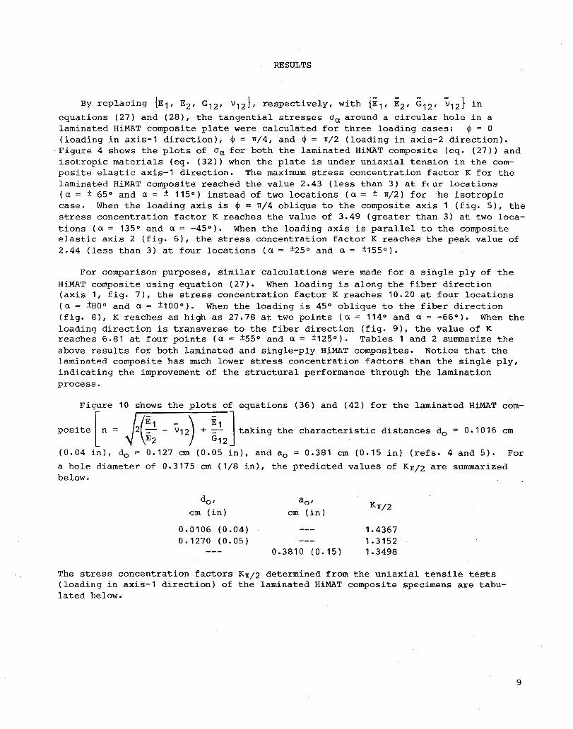
By replacing {E1' E2 , G12 , v 12 }, respectively, with {E 1 , E2 , G12 , V12} in
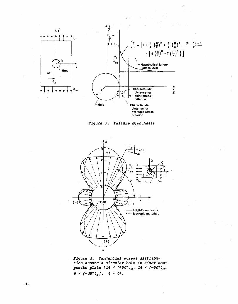
equations (27) and (28), the tangential stresses 0a around a circular hole in a laminated HiMAT composite plate were calculated for three loading cases: ~ = 0 (loading in axis-1 direction), ~ = ~/4, and ~ = ~/2 (loading in axis-2 direction) •
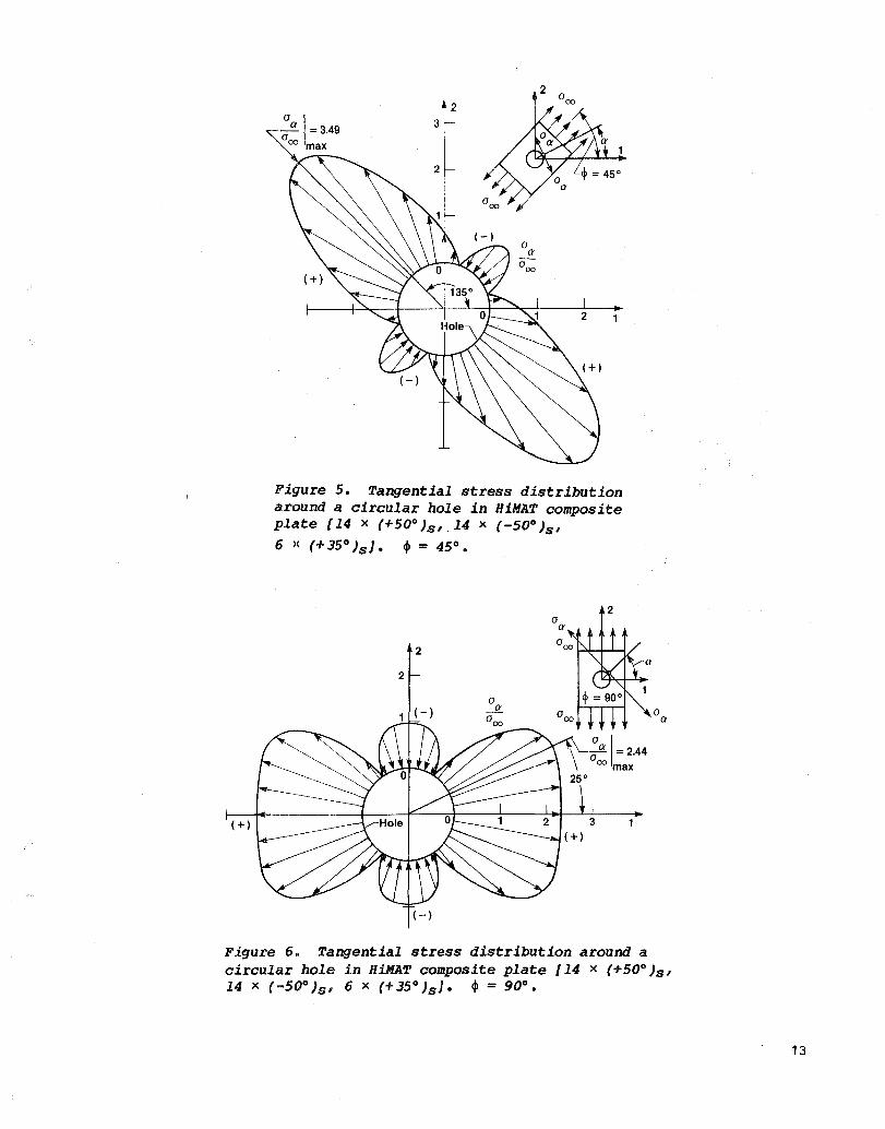
. Figure 4 shows the plots of 0a for both the laminated HiMAT composite (eq. (27» and isotropic materials (eq. (32» when the plate is under uniaxial tension in the composite elastic axis-1 direction. The maximum stress concentration factor K for the laminat.ed HiMAT composite reached the value 2.43 (less than 3) at f(ur locations (a = ± 65° and a = ± 115°) instead of two locations (a = ± ~/2) for 'he isotropic case. When the loading axis is ~ = ~/4 oblique to the composite axis 1 (fig. 5), the stress concentration factor K reaches the value of 3.49 (greater than 3) at two locations (a = 135° and a = ·-45°). When the loading axis is parallel to the composite elastic axis 2 (fig. 6), the stress concentration factor K reaches the peak value of 2.44 (less than 3) at four locations (a = ±25° and a = ±155°).
For comparison purposes, similar calculations were made for a single ply of the
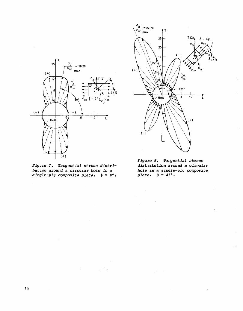
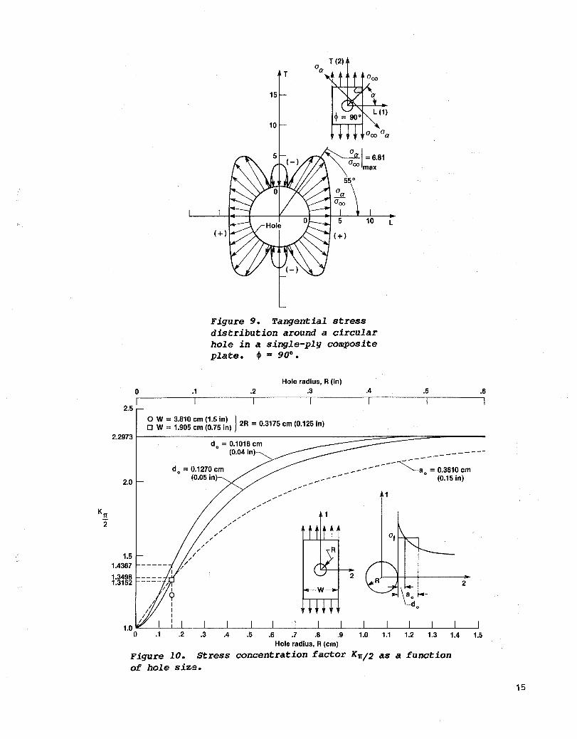
HiMAT composite using equation (27). When loading is along the fiber direction (axis 1, fig. 7), the stress concentration factor K reaches 10.20 at four locations (a = ±80 o and a = ±100 0 ). When the loading is 450 oblique to the fiber direction (fig. 8), K reaches as high as 27.78 at two points (a = 114° and a = -66°). When the loading direction is transverse to the fiber direction (fig. 9), the value of K reaches 6.81 at four points (a = ±55° and a = ±125°). Tables 1 and 2 summarize the above results for both laminated and single-ply HiMAT composites. Notice that the laminated composite has much lower stress concentration factors than the single ply, indicating the improvement of the structural performance through the lamination process.
Figure 10 shows the plots of equations (36) and (42) for the laminated HiMAT com
posite [n = 2(~1 - V12) + ~1 ] taking the characteristic distances do = 0.1016 cm E2 G12 .
(0.04 in), do 0.127 cm (0.05 in), and a o = 0.381 cm (0.15 in) (refs. 4 and 5). For
a hole diameter of 0.3175 cm (1/8 in), the predicted values of K~/2 are summarized below.
dOl a o ' K~/2 cm (in) cm (in)
0.0106 (0.04) 1.4367 0.1270 (0.05) 1.3152
0.3810 (0.15) 1.3498
The stress concentration factors K~/2 determined from the uniaxial tensile tests (loading in axis-1 direction) of the laminated HiMAT composite specimens are tabulated below.
9
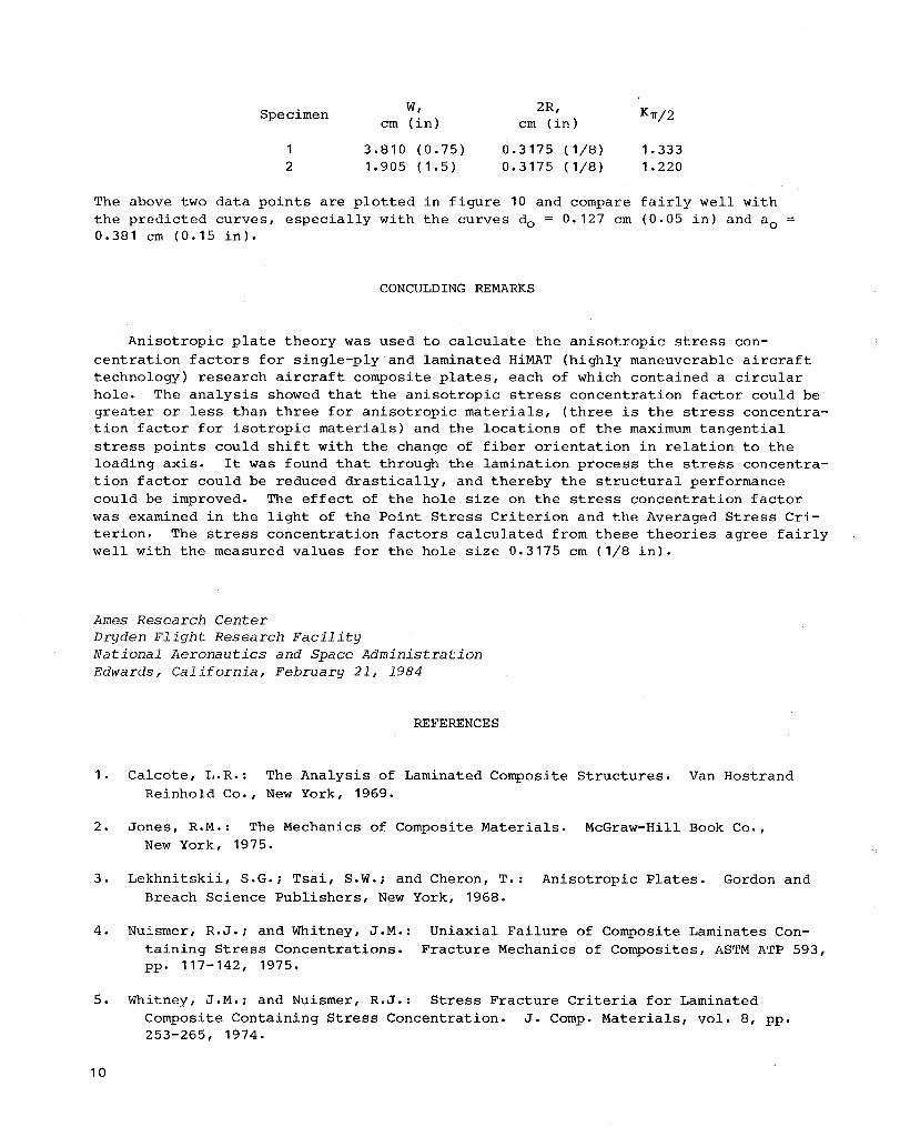
Specimen
1 2
w, cm (in)
3.810 (0.75) 1.905 (1.5)
2R, cm (in)
0.3175 (1/8) 0.3175 (1/8)
Kn/2
1.333 1.220
The above two data points are plotted in figure 10 and compare fairly well with the predicted curves, especially with the curves do = 0.127 cm (0.05 in) and a o 0.381 cm (0.15 in).
CONCULDING REMARKS
Anisotropic plate theory was used to calculate the anisotropic stress concentration factors for single-ply and laminated HiMAT (highly maneuverable aircraft technology) research aircraft composite plates, each of which contained a circular hole. The analysis showed that the anisotropic stress concentration factor could be greater or less than three for anisotropic materials, (three is the stress concentration factor for isotropic materials) and the locations of the maximum tangential stress points could shift with the change of fiber orientation in relation to the loading axis. It was found that through the lamination process the stress concentration factor could be reduced drastically, and thereby the structural performance could be improved. The effect of the hole size on the stress concentration factor was examined in the light of the Point Stress Criterion and the Averaged Stress Criterion. The stress concentration factors calculated from these theories agree fairly well with the measured values for the hole size 0.3175 cm (1/8 in).
Ames Research Center Dryden Flight Research Facility National Aeronautics and Space Administration Edwards, California, February 21, 1984
REFERENCES
1. Calcote, L.R.: The Analysis of Laminated Composite Structures. Van Hostrand Reinhold Co., New York, 1969.
2. Jones, R.M.: The Mechanics of Composite Materials. McGraw-Hill Book Co., New York, 1975.
3. Lekhnitskii, S.G.; Tsai, S.W.; and Cheron, T.: Anisotropic Plates. Gordon and Breach Science Publishers, New York, 1968.
4. Nuismer, R.J.; and Whitney, J.M.: Uniaxial Failure of Composite Laminates Containing Stress Concentrations. Fracture Mechanics of Composites, ASTM ATP 593, pp. 117-142, 1975.
5. Whitney, J.M.; and Nuismer, R.J.: Stress Fracture Criteria for Laminated Composite Containing Stress Concentration. J. Compo Materials, vol. 8, pp. 253-265, 1974.
10
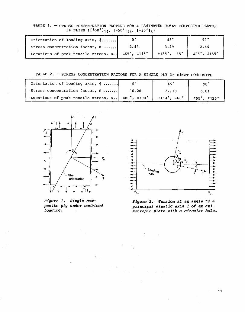
TABLE 1. - STRESS CONCENTRATION FACTORS FOR A LAMINATED HiMAT COMPOSITE PLATE, 34 PLIES ([±500]14' [-50°]14' [+35°]6)
Orientation of loading axis, ¢> ••••••• 0° 45° 90°
Stress concentration factor, K ••••••• 2.43 3.49 2.44
Locations of peak tensile stress, n •• ±65 ° , ±115° +135°, -45° ±25 ° , ±155°
TABLE 2. - STRESS CONCENTRATION FACTORS FOR A SINGLE PLY OF HiMAT COMPOSITE
Orientation of loading axis, </> ....... O· 45 ° 90 °
stress concentration factor, K ••••••• 10.20 27.78 6.81
Locations of peak tensile stress, n •• ±80 ° , ±100° +114°, -66° ±55°, ±125°
L
r 1 t t -- -"----
°2 J
--i --j --j --j --~
2
--J --j Fiber t orientation ~ -- T --+ +-+-+~+;;;+ --
Figure 1. Single composite ply under combined loading.
~ Loading aXis
a 00
Figure 2. Tension at an angle to a principal elastic axis 1 of an anisotropic plate with a circular hole.
11
12
y (1)
~ = [1 + .1 (.!!.)2 + 1. (.!!.)4 _ (n + 1) - 3 0 00 2 x 2 x 2
X{5(ft-7(~)8}]
Characteristic distance for
a 0 point stress
Hole
~ criterion
Characteristic distance for averaged stress criterion
Figure 3. Failure hypothesis
2
"',.. ..... 3 ,/ (+)
I
-- HiMAT composite --- Isotropic materials
Figure 4. Tangential stress distribution around a circular hole in HiMAT composite plate [14 x (+500 )s' 14 x (-500 )s' 6 x (+35°)s1. If! = 0°.
x (2)
(+)
2
:a 1=3.49 00 max
3
..
Figure 5. Tangential stress distribution around a circular hole in HiMAT composite plate [14 x (+500
) sl 14 x (-500 )sl 6 )( (+35° )s1. ~ = 45°.
2
(-)
Figure 6. Tangential stress distribution around a circular hole in HiMAT composite plate [14 x (+500 )sl 14 x (-50° )s, 6 x (+35° )s). ~ = 90°.
13
14
T
(-)
Figure 7. Tangential stress distribution around a circular hole in a single-ply composite plate. ~ = 0°.
°a I \0 =27.78 \00 max
T
T (2) 25
L
Figure 8. Tangential stress distribution around a circular hole in a single-ply composite plate. ~ = 45°.
o I
2.5
.1
T
15
10
?-I =6.81 00 max
Figure 9. Tangential stress distribution around a circular hole in a single-ply composite plate. ~ = 90°.
.2 Hole radius, R (in)
.3 .4
o w = 3.810 em (1.5 in) I . o W = 1.905 em (0.75 in) 2R = 0.3175 em (0.125 In)
L
.5 .6
2.2973 1--------:---::------------=:::::==--=:::::=----do = 0.1016 em
(0.04 in)
2.0
1.5 1.4367
1.3498 1.3152
do = 0.1270 em (0.05 in)
.2 .3 .4 .5 .6
------------------~:o-= 0.3810 em
- (0.15 in)
2
.7 .8 .9 Hole radius, R (em)
Figure 10. Stress concentration factor K~/2 as a function of hole size.
15
1. Report No. I 2. Government Accession No. 3. Recipient's Catalog No.
NASA TM-86038
4. Title and Subtitle 5. Report Date
December 1985 STRESS CONCENTRATION AROUND A SMALL CIRCULAR HOLE 6. Performing Organization Code IN THE HiMAT COMPOSITE PLATE
7. Author(s) 8. Performing Organization Report No. William L. Ko H-1235
10. Work Unit No.
9. Performing Organization Name and Address RTOP 533-02-71
NASA Ames Research Center Dryden Flight Research Facility
11. Contract or Grant No.
P.O. Box 273 Edwards, CA 93523 13. Type of Report and Period Covered
12. Sponsoring Agency Name and Address Technical Memorandum
National Aeronautics and Space Administration 14. Sponsoring Agency Code Washington, D.C. 20546
15. Supplementary Notes
16. Abstract
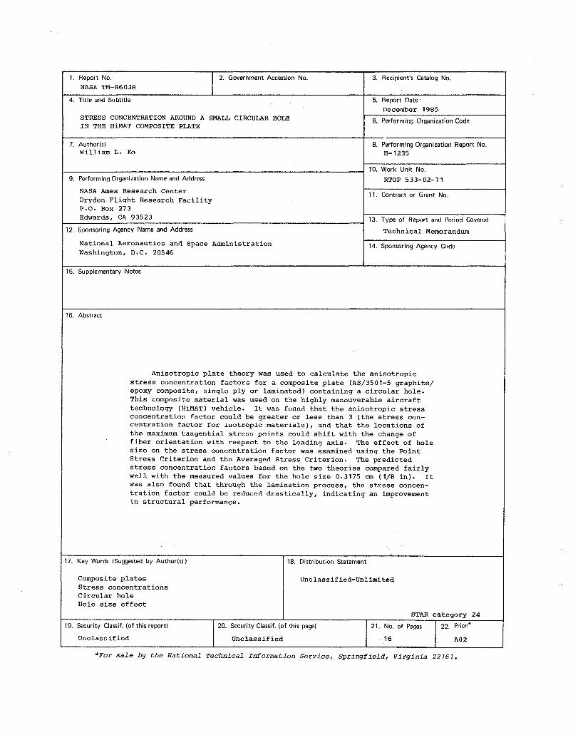
Anisotropic plate theory was used to calculate the anisotropic stress concentration factors for a composite plate (AS/3501-5 graphite/ epoxy composite, single ply or laminated) containing a circular hole. This composite material was used on the highly maneuverable aircraft technology (HiMAT) vehicle. It was found that the anisotropic stress concentration factor could be greater or less than 3 (the stress con-centration factor for isotropic materials), and that the locations of the maximum tangential stress points could shift with the change of fiber orientation with respect to the loading axis. The effect of hole size on the stress concentration factor was examined using the Point Stress Criterion and the Averaged Stress Criterion. The predicted stress concentration factors based on the two theories compared fairly well with the measured values for the hole size 0.3175 ern (1/8 in). It was also found that through the lamination process, the stress concen-tration factor could be reduced drastically, indicating an improvement in structural performance.
17. Key Words (Suggested by Author(s» 18. Distribution Statement
Composite plates Unclassified-Unlimited Stress concentrations Circular hole Hole size effect
STAR category 24
19. Security Classif. (of this report) 20. Security Classif. (of this page) 21. No. of Pages /22. Price'
Unclassified Unclassified 16 A02
*For sale by the National Technical Information Service, Springfield, Virginia 22161.
End of Document


![ANALYSIS AND MITIGATION OF STRESS CONCENTRATION …ijirset.com/upload/july/45_ ANALYSIS.pdf · Toubal et al. [13] studied experimentally for stress concentration in a circular hole](https://img.pdfslide.us/doc/110x75/5e1d1b42e161f12bce24af38/analysis-and-mitigation-of-stress-concentration-analysispdf-toubal-et-al-13.jpg)