Embed Size (px)
Citation preview
666
Journal of Engineering Sciences
Assiut University
Faculty of Engineering
Vol. 42
No. 3
May 2014
Pages: 666–682
* Corresponding author.
Email address:[email protected]
THE EFFECT OF USING FALSE
CEILING ON ROOF COOLING LOAD
ALI H. Abdel Razek 1, *, Ibrahim S. Taha
2,
Mahmoud G. Morsy 3 and Ali K. Abdel-Rahman
4
1,2,3,4Staff in mechanical Engineering Dept., Faculty of EngineeringAssiut University, 71516 Assiut
Received 15 January 2014; accepted 20 February 2014
ABSTRACT
Using of false ceilings (FC) for decoration and covering different ducts in modern buildings is
spreading so much nowadays. This paper tries to find a new employment and other benefits for
using false ceilings (FC).A one dimensional transient mathematical model has been established to
study the effects of using false ceiling on reduction of heat gained from concrete roof of controlled
temperature space. The effect of using false ceiling (FC), with and without adding reflector sheet on
its upper side facing to concrete roof on the room cooling load is studied by modeling and solving
the transient heat transfer processes in the different components of the space. The results showed
that using of false ceiling only without reflector sheet reduces heatgain introduced to space through
24 hours by 66.8%, while using of false ceiling with reflector sheet increases the reduction percent
of heat gained from concrete roof to be 81.6% for the same period.
Keywords: Concrete Roof; False Ceiling; Reflector Sheet; roof cooling load
1. Introduction
As fifty percent of external heat gain in the buildings is from the roof [1], therefore a lot
of experimental and analytical studies all over the world had been performed to decrease that
load. Removing of such load from buildings by active systems (like mechanical air
conditioning systems) becomes very expensive specially with the fast spreading of energy
crises around the world. Using of passive techniques to reduce buildings heat load have been
very important. Using of materials of low conductance and heat capacitance, wind tower, and
doomed roof were efficient methods. However such methods are difficult to be used in the
high modern buildings. Most roofs nowadays are flat and made of high thermal capacitance
material like concrete. So they need special methods to decrease their loads. Ciampi
et al.[2] performed analytical study of tilted ventilated and micro ventilated roofs to
investigate the reduction in summer thermal loads. They built their mathematical models of
ventilated roof as turbulent flow model and for small thickness duct (micro ventilated roof)
with laminar flow model. They studied two different roof designs. One of them was
667
Ali H. Abdel Razek et al., The effect of using false ceilingon roof cooling load
constructed from copper plate as upper slab and rigid fiberglass panel as lower slab, while
the second one was constructed from a tile and wooden rafters as upper part with rigid
fiberglass panel as lower part of the roof. They considered room temperature to have a
constant value in all cases and presented one dimensional thermal energy balance model.
They concluded that:
1. The roof having a tile as upper slab reduces heat gain comparing with the other of
copper sheet.
2. Energy saving in the case of well-designed roof can be more than 30% with large
duct height (0.08 m) and not exceeding 15% for micro ventilated design (.04 m).
3. Heat gain in case of closed duct is more than for open duct; so using roof design
with closed duct is better in winter.
Biwole et al.[3] studied the effect of adding metallic screen sheet above sheet metal
roof to make an inclined open channel to enhance natural convection over roof surface.
They studied this double skin roof numerically by bi-dimensional numerical method and
validated it by experimental work. The effect of thermal radiation properties of the roof
components like emittance and reflectance on temperature profile was investigated for
different channel cross-sections. They concluded that, there is enhancement in natural
ventilation by increasing tilted angle and cavity width. But these factors did not have great
effects on thermal radiation comparing with emittance reduction of sheet metal. They
found a reduction of heat gain by about 58% when emittance of all components was
reduced from 0.8 to 0.15. Fracastoro et al.[4], presented a steady state analytical model to
study reduction of heat gain by using under roof air cavities, for both opened (ventilated)
and closed (unventilated) ones. They found that ventilated roofs may lead to a reduction up
to fifty percentof the load for closed air cavity roofs.
This paper aims to study the effect of different parameters of false ceiling (FC) on the roof
load. The false ceiling is usually used to cover ducts or pipes passed under roof, and become a
part of the internal decoration of buildings. The objective of this work is to study the influence
of false ceiling on heat load coming from concrete roof facing the sky by one dimensional
transient model. In this work space temperature is controlled and the walls are completely
insulated. So only heat gain will come from roof .Theoretical model used will treat three cases:
Case one: Concrete roof only with no false ceiling (FC)
Case two: Concrete roof with false ceiling (FC) making a closed cavity
Case three: The pervious case but using reflector sheet(FC-R) on the upper face
of false ceiling which is facing the concrete roof.
2. Theoretical model
2.1. System and assumptions
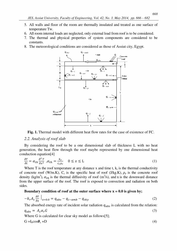
Figure (1) shows the dimensions of the room that will be studied and the different heat
flow rates. For the system shown in Fig.(1), the following assumptions are taken into
consideration when dealing with energy balances on the various components of the system
1. Heat transfer through the concrete roof, which is considered to be flat and
horizontal, is one dimensional.
2. Air gap (space between roof and false ceiling) is thermally treated as homogeneous
gap with bulk temperature of Tav.
3. False ceiling is thermally treated as a lumped heat capacitance system.
4. Room space has a constant temperature of Tin.
668
JES, Assiut University, Faculty of Engineering, Vol. 42, No. 3, May 2014, pp. 666 – 682
5. All walls and floor of the room are thermally insulated and treated as one surface of
temperature Tw.
6. All room internal loads are neglected, only external load from roof is to be considered.
7. The thermal and physical properties of system components are considered to be
constants.
8. The meteorological conditions are considered as those of Assiut city, Egypt.
Fig. 1. Thermal model with different heat flow rates for the case of existence of FC.
2.2. Analysis of roof slab
By considering the roof to be a one dimensional slab of thickness L with no heat
generation, the heat flow through the roof maybe represented by one dimensional heat
conduction equation[4] , (1)
Where T is the roof temperature at any distance x and time t, kr is the thermal conductivity
of concrete roof (W/m.K), Cr is the specific heat of roof (J/kg.K), is the concrete roof
density (kg/m3), is the thermal diffusivity of roof (m
2/s), and is the downward distance
from the upper surface of the roof. The roof is exposed to convection and radiation on both
sides.
Boundary condition of roof at the outer surface where = 0.0 is given by; (2)
The absorbed energy rate of incident solar radiation is calculated from the relation: (3)
Where G is calculated for clear sky model as follows[5];
G =Ibcos�z +D (4)
669
Ali H. Abdel Razek et al., The effect of using false ceilingon roof cooling load
The convective heat transfer between roof and ambient air is calculated from the
relation; (5)
and the convective heat transfer coefficient at the outer side of concrete roof is
calculated from the relation[6] (6)
Where is the wind velocity in m /s. The value of in Assiut town, Egypt is
usually between 1.5 – 3.0 m/s around year.
Ambient temperature Tamb and sky temperature Tsky are calculated by the relations[5] [ ] (7) , and are in K. (8)
Where, Tmax and Tmin are the day maximum and minimum temperatures and is the
time in hours measured from midnight. The radiation heat transfer to sky can be
calculated by the relation: , and are in K (9)
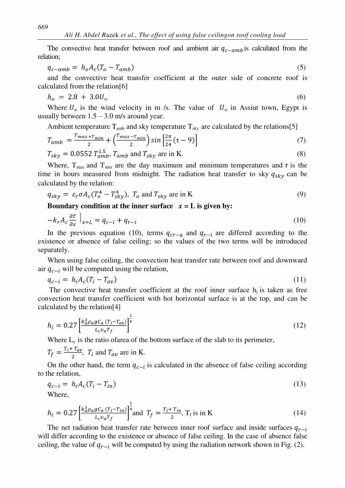
Boundary condition at the inner surface x = L is given by: (10)
In the previous equation (10), terms and are differed according to the
existence or absence of false ceiling; so the values of the two terms will be introduced
separately.
When using false ceiling, the convection heat transfer rate between roof and downward
air will be computed using the relation, (11)
The convective heat transfer coefficient at the roof inner surface hi is taken as free
convection heat transfer coefficient with hot horizontal surface is at the top, and can be
calculated by the relation[4] [ ] (12)
Where Lc is the ratio ofarea of the bottom surface of the slab to its perimeter, , and are in K.
On the other hand, the term is calculated in the absence of false ceiling according
to the relation, (13)
Where, [ ] and , Tf is in K (14)
The net radiation heat transfer rate between inner roof surface and inside surfaces will differ according to the existence or absence of false ceiling. In the case of absence false
ceiling, the value of will be computed by using the radiation network shown in Fig. (2).
670
JES, Assiut University, Faculty of Engineering, Vol. 42, No. 3, May 2014, pp. 666 – 682
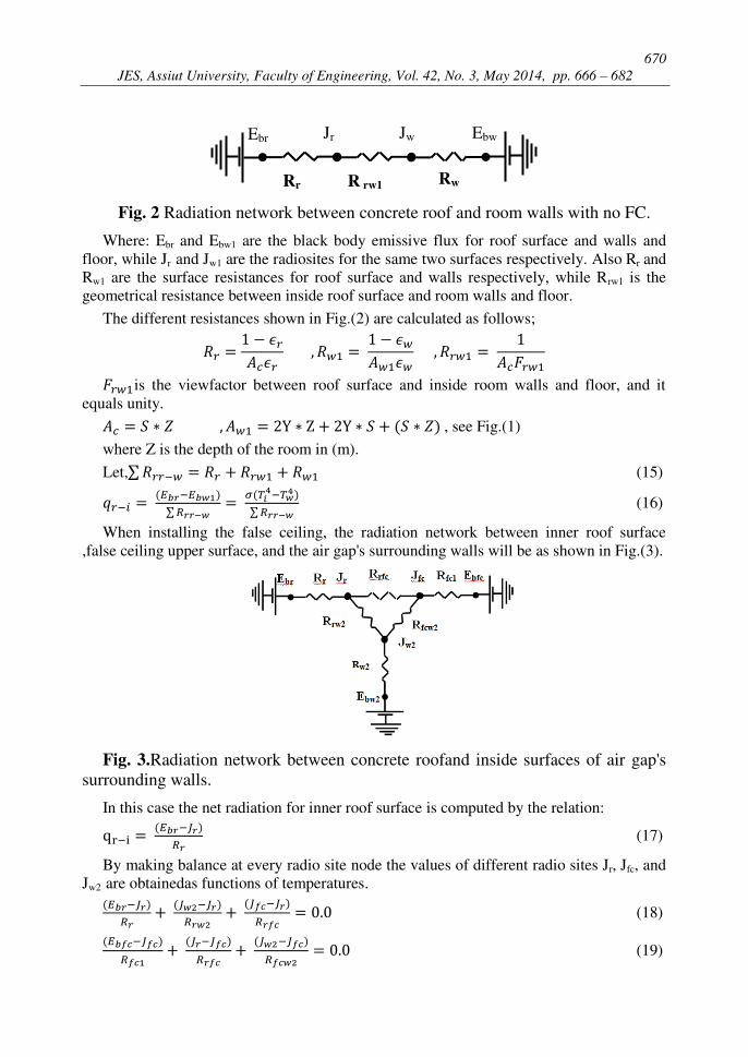
Ebr Jr Jw Ebw
Rr R rw1 Rw
Fig. 2 Radiation network between concrete roof and room walls with no FC.
Where: Ebr and Ebw1 are the black body emissive flux for roof surface and walls and
floor, while Jr and Jw1 are the radiosites for the same two surfaces respectively. Also Rr and
Rw1 are the surface resistances for roof surface and walls respectively, while Rrw1 is the
geometrical resistance between inside roof surface and room walls and floor.
The different resistances shown in Fig.(2) are calculated as follows; is the viewfactor between roof surface and inside room walls and floor, and it
equals unity. , see Fig.(1)
where Z is the depth of the room in (m).
Let,∑ (15) ∑ ∑ (16)
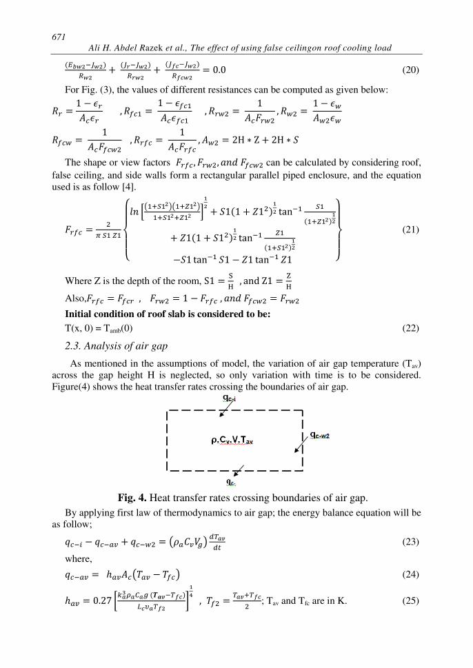
When installing the false ceiling, the radiation network between inner roof surface
,false ceiling upper surface, and the air gap's surrounding walls will be as shown in Fig.(3).
Fig. 3.Radiation network between concrete roofand inside surfaces of air gap's
surrounding walls.
In this case the net radiation for inner roof surface is computed by the relation: (17)
By making balance at every radio site node the values of different radio sites Jr, Jfc, and
Jw2 are obtainedas functions of temperatures. (18) (19)
671
Ali H. Abdel Razek et al., The effect of using false ceilingon roof cooling load (20)
For Fig. (3), the values of different resistances can be computed as given below:
The shape or view factors can be calculated by considering roof,
false ceiling, and side walls form a rectangular parallel piped enclosure, and the equation
used is as follow [4].
{ [( )( ) ] }
(21)
Where Z is the depth of the room,
Also,
Initial condition of roof slab is considered to be:
T(x, 0) = Tamb(0) (22)
2.3. Analysis of air gap
As mentioned in the assumptions of model, the variation of air gap temperature (Tav)
across the gap height H is neglected, so only variation with time is to be considered.
Figure(4) shows the heat transfer rates crossing the boundaries of air gap.
Fig. 4. Heat transfer rates crossing boundaries of air gap.
By applying first law of thermodynamics to air gap; the energy balance equation will be
as follow; ( ) (23)
where, ( ) (24) [ ] ; Tav and Tfc are in K. (25)
672
JES, Assiut University, Faculty of Engineering, Vol. 42, No. 3, May 2014, pp. 666 – 682 (26)
[ [ ] ⁄ ]
for vertical walls[4]. (27)
where, ,Tw2 and Tav are in K, Lc= H.
Hence; [ ( )
[ ] ⁄ ]
(28)
Initial condition for air gap is considered as follow:-
Tav (0) = Tamb(0) (29)
2.4. Analysis of air gap's walls
The energy balance equation for walls surrounding the air gap is as follow; (30)
Initial condition for air gap's wall: Tw2(0) = Tamb(0) (31)
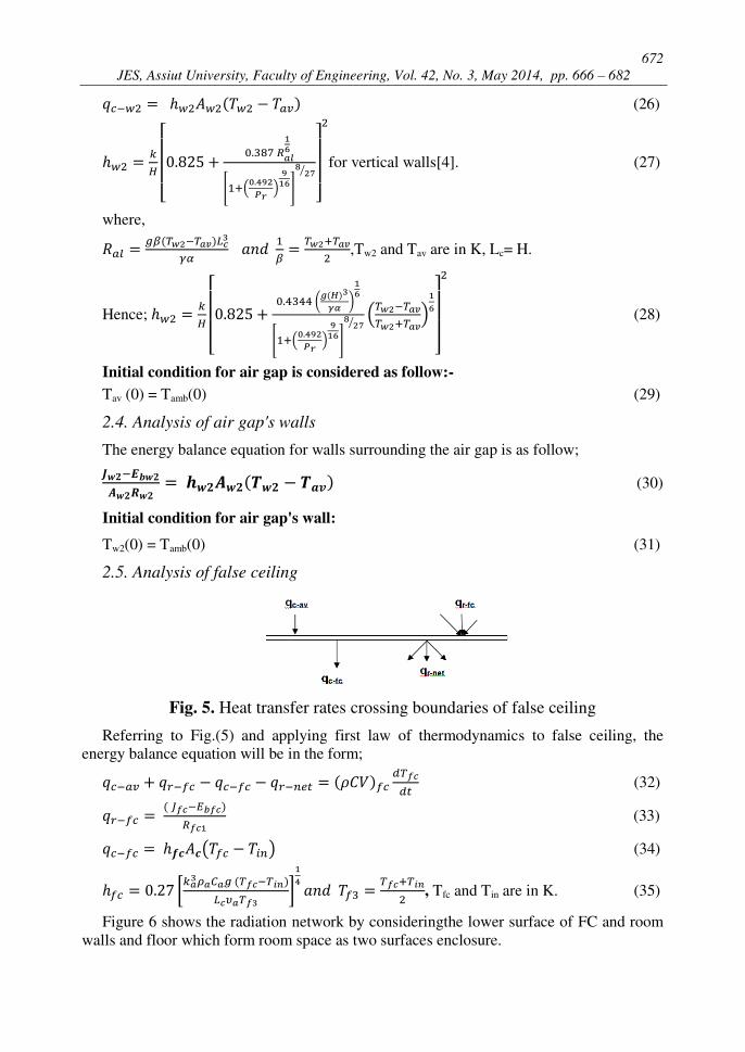
2.5. Analysis of false ceiling
Fig. 5. Heat transfer rates crossing boundaries of false ceiling
Referring to Fig.(5) and applying first law of thermodynamics to false ceiling, the
energy balance equation will be in the form; (32) (33) ( ) (34) [ ] , Tfc and Tin are in K. (35)
Figure 6 shows the radiation network by consideringthe lower surface of FC and room
walls and floor which form room space as two surfaces enclosure.
673
Ali H. Abdel Razek et al., The effect of using false ceilingon roof cooling load
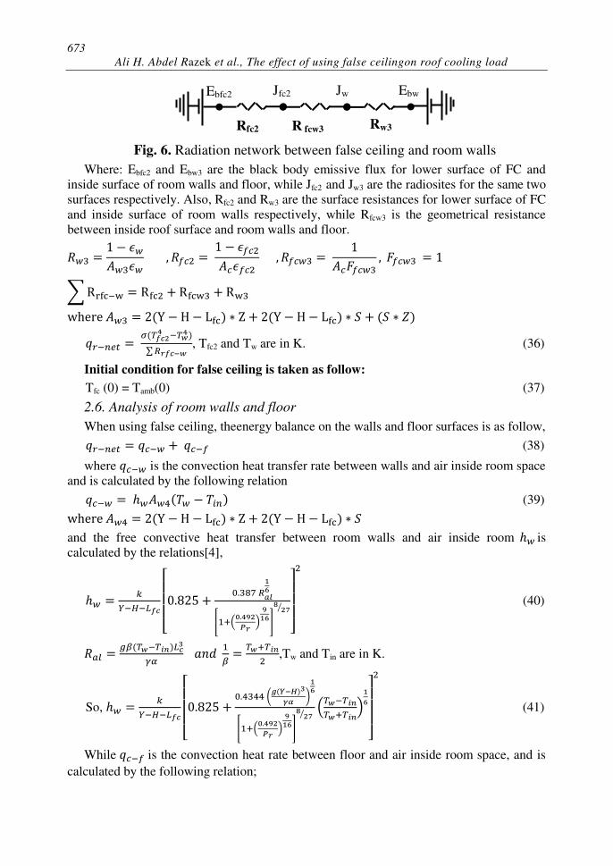
Fig. 6. Radiation network between false ceiling and room walls
Where: Ebfc2 and Ebw3 are the black body emissive flux for lower surface of FC and
inside surface of room walls and floor, while Jfc2 and Jw3 are the radiosites for the same two
surfaces respectively. Also, Rfc2 and Rw3 are the surface resistances for lower surface of FC
and inside surface of room walls respectively, while Rfcw3 is the geometrical resistance
between inside roof surface and room walls and floor. ∑ ∑ , Tfc2 and Tw are in K. (36)
Initial condition for false ceiling is taken as follow: Tfc (0) = Tamb(0) (37)
2.6. Analysis of room walls and floor
When using false ceiling, theenergy balance on the walls and floor surfaces is as follow, (38)
where is the convection heat transfer rate between walls and air inside room space
and is calculated by the following relation (39)
and the free convective heat transfer between room walls and air inside room is
calculated by the relations[4],
[ [ ] ⁄ ]
(40)
,Tw and Tin are in K.
So, [ ( )
[ ] ⁄ ]
(41)
While is the convection heat rate between floor and air inside room space, and is
calculated by the following relation;
Ebfc2 Jfc2 Jw Ebw
Rfc2 R fcw3 Rw3
674
JES, Assiut University, Faculty of Engineering, Vol. 42, No. 3, May 2014, pp. 666 – 682 (42)
Where [ ] (43)
In the absence of false ceiling, the energy balance equation on the walls and floor
surfaces will be as follows, (44) ∑ (45)
From Fig.(2):∑ (46)
The value of in equation (45) will differ from the same coefficient in equation (41)
because the walls height is changed. So of equation (45) is obtained from the following
relation:
[ ( )
[ ] ⁄ ]
(47)
2.7. Analysis of room air
As stated before, the temperature of room air is assumed to be controlled at a constant
value Tin. The energy balance equation in the absence of false ceiling is given by: (48)
Where is the cooling load delivered out by refrigerating machine, and when using
false ceiling, the energy balance equation will be in the form (49)
3. Method of solution
In this model there is a set of unknowns which are to be obtained to estimate different
heat transfer rates in the model. These unknowns are roof temperature T(x,t), air gap
temperature Tav(t), air gap's walls temperature Tw2, false ceiling temperature Tfc(t), and
room walls temperature Tw(t).
The governing equations of the system components (roof, air gap, air gap's walls, false
ceiling, and space walls and floor) are simultaneous partial and ordinary differential
equations and algebraic equations. Because the boundary conditions are time dependent,
there is no available closed form solution for such equations. The time duration of one day
is discretized into time interval each of one hour.
The following steps are followed to obtain the solution at the end of each time interval.
1. The time interval for solution t=3600 s.
2. The roof slab is divided into m (15) elements with the upper and lower elements
are having half the thickness of the element. Equation (1) is applied to the interior
elements, while the boundary equations (2, 10) are applied to the upper and lower
elements respectively.
675
Ali H. Abdel Razek et al., The effect of using false ceilingon roof cooling load
3. The differential terms are discretized using a finite difference scheme.
4. Guessed values for the gap's air, air gap's surrounding walls, and false ceiling
temperatures are used to determine the temperatures of the roof elements (values at
starting time are used).
5. The gap air temperature Tav, and false ceiling temperature Tfcare obtained using equations
(23, 32) by applying the 4th order Runge-Kutta technique using the results of the ceiling
temperatures as well as the guessed value of space walls and floor temperature.
6. The air gap's surrounding walls is thus obtained using equation (30).
7. The space walls and floor temperature is thus obtained using equation (38).
8. Multiple iteration loops are then applied through Fortran code to obtain the
solution for the temperatures of all components at the end of the time interval.
9. The procedure given above is repeated for all time intervals to cover the whole day.
3.1. Model dimensions and thermophysical properties of its material
The dimensions used in this analysis are given in table 1. Zach et al.[7] presented an
empirical study to evaluate thermal conductivity of lightweight concrete. The density and
thermal conductivity of roof material were determined from [7]. Thermal radiation
properties as solar absorbance and long wave emittance were obtained from[8]. Infrared
emittance of wall and AL foil used as reflector sheet on false ceiling were taken from[9],
while properties of false ceiling (density, specific heat, and thermal conductivity) were
taken from a specification sheet of commercial false ceiling board. The properties used in
this analysis are given in Table 2.
Table 1.
Dimensions of model
Table 2. Properties of selected materials
material Density(kg/m3) Cp(J/kg.K) k(W/m.K) Emittance Absorbtance
Concrete Roof 2300 1000 0.4118 0.9 0.8
False Ceiling 600 1090 0.191 0.8
Reflector − 0.09
Walls − − − 0.96 −
Air 1.205 1005 0.0257 − −
3.2. Validation of theoretical model
This model has been solved using meteorological data conditions for Assiut city, Egypt
(27.11o
north, 30.04o
east) in summer seasonon 21st June. The maximum and minimum
temperatures are 43oC and 26
oC respectively and constant indoor temperature Tin equal
200C. The present computer code was validated by comparing numerical results with
experimental results published byJo et al.[10].The described conditions in [10] included site
(Phoenix, Arizona, USA 33.34o
north and longitude 112.06o
west), climatic conditions, and
indoor air conditions were taken in consideration and adopted in the computer code for
comparing of results. The comparison was made for the outer surface temperature of an
Dimension L H Lfc Y S Z
Value (m) 0.12 0.60 0.01 3.0 3.0 2.0
676
JES, Assiut University, Faculty of Engineering, Vol. 42, No. 3, May 2014, pp. 666 – 682
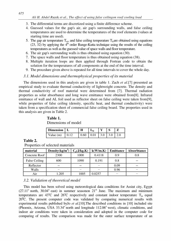
ordinary roof (which has symbol B in [10]) having no thermal reating. Figure (7) shows the
differences between theoretical results of case one and experimental data taken from [10].
The correlation coefficient between experimental data and theoretical results is 0.98 and
standard error is 2.23. So a good agreement has been achieved by the model.
Fig. 7.Variation of experimental data of [10] and theoretical results of outside
roof surface temperaturesduring day time for case one (no FC)
4. Results and discussion
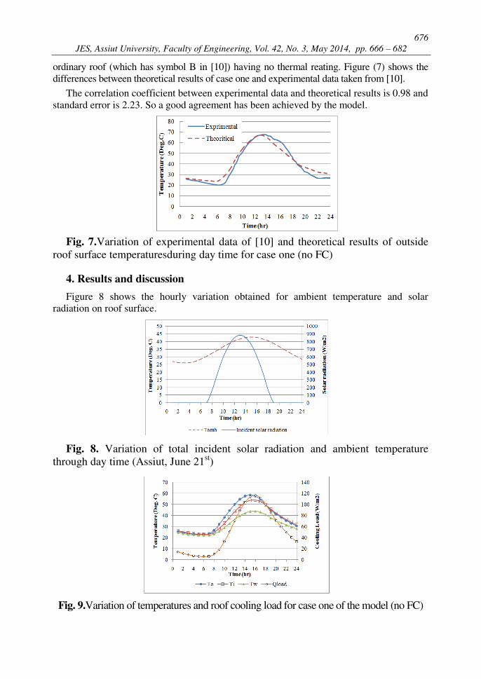
Figure 8 shows the hourly variation obtained for ambient temperature and solar
radiation on roof surface.
Fig. 8. Variation of total incident solar radiation and ambient temperature
through day time (Assiut, June 21st)
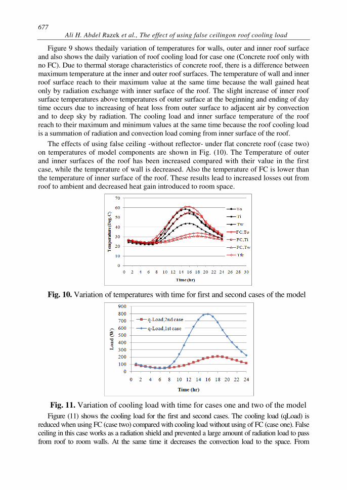
Fig. 9.Variation of temperatures and roof cooling load for case one of the model (no FC)
677
Ali H. Abdel Razek et al., The effect of using false ceilingon roof cooling load
Figure 9 shows thedaily variation of temperatures for walls, outer and inner roof surface
and also shows the daily variation of roof cooling load for case one (Concrete roof only with
no FC). Due to thermal storage characteristics of concrete roof, there is a difference between
maximum temperature at the inner and outer roof surfaces. The temperature of wall and inner
roof surface reach to their maximum value at the same time because the wall gained heat
only by radiation exchange with inner surface of the roof. The slight increase of inner roof
surface temperatures above temperatures of outer surface at the beginning and ending of day
time occurs due to increasing of heat loss from outer surface to adjacent air by convection
and to deep sky by radiation. The cooling load and inner surface temperature of the roof
reach to their maximum and minimum values at the same time because the roof cooling load
is a summation of radiation and convection load coming from inner surface of the roof.
The effects of using false ceiling -without reflector- under flat concrete roof (case two)
on temperatures of model components are shown in Fig. (10). The Temperature of outer
and inner surfaces of the roof has been increased compared with their value in the first
case, while the temperature of wall is decreased. Also the temperature of FC is lower than
the temperature of inner surface of the roof. These results lead to increased losses out from
roof to ambient and decreased heat gain introduced to room space.
Fig. 10. Variation of temperatures with time for first and second cases of the model
Fig. 11. Variation of cooling load with time for cases one and two of the model
Figure (11) shows the cooling load for the first and second cases. The cooling load (qLoad) is
reduced when using FC (case two) compared with cooling load without using of FC (case one). False
ceiling in this case works as a radiation shield and prevented a large amount of radiation load to pass
from roof to room walls. At the same time it decreases the convection load to the space. From
678
JES, Assiut University, Faculty of Engineering, Vol. 42, No. 3, May 2014, pp. 666 – 682
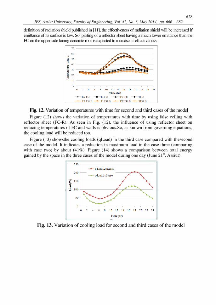
definition of radiation shield published in [11], the effectiveness of radiation shield will be increased if
emittance of its surface is low. So, pasting of a reflector sheet having a much lower emittance than the
FC on the upper side facing concrete roof is expected to increase its effectiveness.
Fig. 12. Variation of temperatures with time for second and third cases of the model
Figure (12) shows the variation of temperatures with time by using false ceiling with
reflector sheet (FC-R). As seen in Fig. (12), the influence of using reflector sheet on
reducing temperatures of FC and walls is obvious.So, as known from governing equations,
the cooling load will be reduced too.
Figure (13) showsthe cooling loads (qLoad) in the third case compared with thesecond
case of the model. It indicates a reduction in maximum load in the case three (comparing
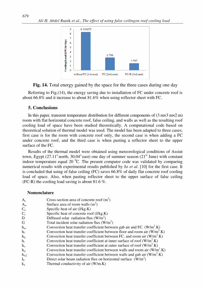
with case two) by about (41%). Figure (14) shows a comparison between total energy
gained by the space in the three cases of the model during one day (June 21st, Assiut).
Fig. 13. Variation of cooling load for second and third cases of the model
679
Ali H. Abdel Razek et al., The effect of using false ceilingon roof cooling load
Fig. 14. Total energy gained by the space for the three cases during one day
Referring to Fig.(14), the energy saving due to installation of FC under concrete roof is
about 66.8% and it increase to about 81.6% when using reflector sheet with FC.
5. Conclusions
In this paper, transient temperature distribution for different components of (3 m×3 m×2 m)
room with flat horizontal concrete roof, false ceiling, and walls as well as the resulting roof
cooling load of space have been studied theoretically. A computational code based on
theoretical solution of thermal model was used. The model has been adapted to three cases;
first case is for the room with concrete roof only, the second case is when adding a FC
under concrete roof, and the third case is when pasting a reflector sheet to the upper
surface of the FC.
Results of the thermal model were obtained using meteorological conditions of Assiut
town, Egypt (27.11o north, 30.04
o east) one day of summer season (21
st June) with constant
indoor temperature equal 20 0C. The present computer code was validated by comparing
numerical results with experimental results published by Jo et al. [10] for the first case. It
is concluded that using of false ceiling (FC) saves 66.8% of daily flat concrete roof cooling
load of space. Also, when pasting reflector sheet to the upper surface of false ceiling
(FC-R) the cooling load saving is about 81.6 %.
Nomenclature
Ac Cross-section area of concrete roof (m2)
Aw Surface area of room walls (m2)
Ca Specific heat of air (J/kg.K)
Cr Specific heat of concrete roof (J/kg.K)
D Diffused solar radiation flux (W/m2)
G Total incident solar radiation flux (W/m2)
hav Convection heat transfer coefficient between gab air and FC. (W/m2.K)
hf Convection heat transfer coefficient between floor and room air (W/m2.K)
hfc Convection heat transfer coefficient between FC. and room air (W/m2.K)
hi Convection heat transfer coefficient at inner surface of roof (W/m2.K)
ho Convection heat transfer coefficient at outer surface of roof (W/m2.K)
hw Convection heat transfer coefficient between walls and room air (W/m2.K)
hw2 Convection heat transfer coefficient between walls and gab air (W/m2.K)
Ib Direct solar beam radiation flux on horizontal surface (W/m2)
ka Thermal conductivity of air (W/m.K)
680
JES, Assiut University, Faculty of Engineering, Vol. 42, No. 3, May 2014, pp. 666 – 682
kr Thermal conductivity of concrete roof (W/m.K)
L Thickness (m)
qabs Absorbed portion of incident solar radiation by roof (W)
qc-amb Convection heat transfer rate at outer surface of roof (W)
qc-av Convection heat transfer rate between gab air and FC. (W)
qc-fc Convection heat transfer rate between FC and inside room air. (W)
qc-i Convection heat transfer rate at inner surface of roof (W)
qc-w2 Convection heat transfer rate between walls and gab air. (W)
qload Cooling load (W)
qr-fc Net radiation heat transfer rate gained by FC (W)
qr-i Net radiation heat transfer rate at inner surface of concrete roof (W)
qr-net Net radiation heat transfer rate for lower surface of FC (W)
qsky Radiation heat transfer rate between roof and sky (W)
t Time (s)
T Temperature (o C or K)
**
Tamb Ambient air temperature (o C)
Tav Air gab Temperature (o C)
Ti Inside roof surface temperature (o C)
Tin Design inside air temperature (o C)
To Outside roof surface temperature (o C)
Tsky Sky temperature (o C)
Tw Temperature of wall surrounding room space (o C)
Tw2 Temperature of wall surrounding air gab space (o C)
U∞ Wind velocity (m/s)
Vg Air gab volume (m3)
Greek Symbols
αr Solar absorbtance of concrete roof
αth Thermal diffusivity (m2/s)
εfc Emittance of false ceiling
εr Emittance of concrete roof
υa Kinematic viscosity of air (m2/s)
ρa Density of air (kg/m3)
ρr Density of concrete roof (kg/m3)
σ Stefan-Boltzmann constant (W/m2.K
4)
θz Zenith angle
REFERENCES
[1] Ciampi, M., F. Leccese, and G. Tuoni, Energy analysis of ventilated and microventilated
roofs. Solar Energy. 79(2): p. 183-192, 2005.
[2] Biwole, P., M. Woloszyn, and C. Pompeo, Heat transfers in a double-skin roof ventilated by
natural convection in summer time. Energy and Buildings. 40(8): p. 1487-1497, 2008.
[3] Fracastoro, G., L. Giai, and M. Perino. Reducing cooling loads with under roof air cavities.
Proceedings of AIVC 18th conference, "Ventilation and Cooling". Athhens, Greece,
September 23-26, 1997.
[4] Incropera, F.P., A.S. Lavine, and D.P. DeWitt, Fundamentals of heat and mass transfer. John
Wiley & Sons Incorporated, 2011.
[5] Elsayed, M.M., I.S. Taha, and J.A. Sabbagh, Design of solar thermal systems. Jeddah, Saudi
Arabia: Scientific Publishing Center, King Abdulaziz University. 1994.
[6] Duffie, J.A. and W.A. Beckman, Solar engineering of thermal processes. Third ed., New
York, USA: John Wiley& Sons Inc, 1980.
[7] Zach, J., M. Hubertova, and J. Hroudova. Possibilities of determination of thermal
conductivity of lightweight concrete with utilization of non stationary hot-wire method. The
681
Ali H. Abdel Razek et al., The effect of using false ceilingon roof cooling load
10th international conference of the slovenian society for non-destructive testing, Ljubljana,
Slovenia. Citeseer, 2009.
[8] Jain, A., A step towards urban building information modeling: measuring design and field
variables for an urban heat island analysis, in Faculty of the School of Architecture South
California,USA, 2009.
[9] Eicker, U., Low energy cooling for sustainable buildings. 1st ed., UK: John Wiley & Sons,
Ltd, 2009.
[10] J.H. Jo, J.D.C., J.S. Golden and H.B. , An integrated empirical and modeling methodology
for analyzing solar reflective roof technologies on commercial buildings. Building and
Environment. 45(2): p. 453-460, 2010.
[11] Cengel, Y., Heat Transfer: A Practical Approach. 3 ed., USA: McGraw-Hill, 2003.

682
JES, Assiut University, Faculty of Engineering, Vol. 42, No. 3, May 2014, pp. 666 – 682
قسقف الالتأثير استخدا سقف مع ى الحمل الحرارى ل عخص العربى: الم
إن استخدااات اسستتال القة اتتا دتتو التتاغطية عالخالمتتا تو القةتتتةل القدخ ىتتا داثتتأ الق تتت و ال اغ تتا تت ل لفتذ اسستال القة اتان علتذا ت ا شتت ا هذ اسغتت عهتذا ال تح غ تتع ن غيظتا عأمىتا ع دياىتا ثت خش ا
تت قيذج ةغتضو حتدل اإ ةت دو ال تلا اإ خاتلما لاةاسا أثم ال اةل ال ستال القة تع تو الطستح ال تاىس تثستا ا خت ع اتا طت ان سال اطتن اطمل الفيا ن عقا اا دةاسا ااتة ا بمن استخداا الستال الةمت م عباع فت اا الستال الدتتلو لالتذل و غيظتا خت ستال اة تعص ن عث تإ ال تح إلتو ن استخداا الستال
اىس تثس م س ا ع ت إلو القة ع باعن مت ط ت ان السال ب اةل ال قا دل إلو ا مأ الطسح ال ت ان الستال ثت 6ن.. اةل الط و ال اىس الةتثستا 42% ان الطسح ال قتت دل استخداا الشت ستت ا بم
اةل لخصأ إلو غتدع س ا دىمض الطسح ال مان .ن.6اا السال القة ع إلو ع الزا % دو ىس الىخ