Embed Size (px)
Citation preview

1
The Design of Large Diameter Skim Tanks Using Computational Fluid Dynamics (CFD) For Maximum Oil Removal
15th Annual Produced Water Seminar, January 2005
Hilton NASA Clear Lake, Houston, Texas 77058
Chang-Ming Lee, Ph.D. and Ted Frankiewicz, Ph.D. – NATCO Group Inc. 2950 North Loop West, Suite 750, Houston, TX 77092
Abstract
A new design of internals of a large diameter skim tank is discussed in this paper. Both transient and steady-state CFD simulations were performed to assist the development of the design. Excellent flow distribution was achieved on the inlet distributor as the variance in mass flow rates out of the laterals is less than ± 0.5%. The retention time of produced water was improved to almost 88.5% of the theoretical value with installation of two large perforated plates. Flow path lines were also improved with a much reduced recirculation pattern. This compares with a residence time of 43.4% of the theoretical value for the case without the two large perforated plates. The CFD model predicts that oil droplets size larger than 100 microns are expected to be fully skimmed off without assistance from gas flotation for produced water at the design flow rate of 100,000 BBL/Day.
Introduction
The production of oil and gas is usually accompanied by the extraction of associated water. After the initial bulk separation of the bulk produced fluids, the produced water still contains finely dispersed solids and oil. In order to reduce the contaminant content of dispersed oil in produced water, a large diameter skim tank can be used. Separation is based on the difference between the specific gravity of oil and water and the coalescence of small oil droplets. When the retention time is sufficient, oil floats to the surface and can be separated by an overflow. This technique is only suitable for removing dispersed oil with a sufficiently large particle size. Dissolved materials such as benzene and heavy metals cannot be separated using this technique.
The large diameter skim tank or its modified version, parallel plate interceptor (PPI) or corrugated plate interceptor (CPI), is mostly used as part of a set of techniques for the removal of dispersed oil. In this paper, we discuss the development of a new configuration of internals for a large diameter skim tank. The design of the internals was developed with aid from a series of CFD (Computational Fluid Dynamics) simulations. The objective of the CFD developed design is to provide a large diameter skim tank with optimized flow patterns that maximize liquid residence time and improve oil/water separation.

2
Tank Description
The skim tank is designed for a flow rate of 100,000 BWPD, has a diameter of 80 feet (24.384 m), and a height of 24 feet (7.3152 m). The drawing of the skim tank and the inlet distributor are shown in Figure 1. The inlet distributor consists of a header and eight parallel laterals. Because gas breakout in the oil/water settling zone could seriously degrade separation performance, the fluid inlet incorporates a tangential entry configuration to promote gas/liquid separation prior to liquid reaching the inlet distributor. The open-end of each lateral is directed toward the wall of the skim tank and employs the tank wall as the equivalent of momentum breaker and primary flow deflector.
The skim tank has two large perforated plates. One is located near the inlet distributor and another is located between the three water outlet nozzles and the oil skimming collectors. The large plates are an assembly of several smaller pieces of perforated sheets with thickness of 1/2 inch. The two oil skimming collectors are set at different elevations and they are suitable for operating the skim tank at the high and low levels of 22.5 feet and 17 feet, respectively. There are also three baffles surrounding the outlet nozzles to prevent possible flow short circuiting. Among the three baffles, one solid plate is positioned parallel to the large perforated plate and the other two perforated baffles are both perpendicular to the solid baffle. Model Simplification
The construction of the three-dimensional geometry was based on the dimensions of the skim tank as provided by the field operator and some simplification was required for modeling purpose. The three-dimensional model with a description of internal components of the skim tank is shown in Figure 2. The perforated plates are modeled as “porous-jump” boundaries of zero-thickness – the mathematical equivalent of physical fritted plates – in order to avoid extremely complex meshing of the region around individual orifices. The oil skimming troughs are simplified without the V-notch slot details and their inclination. In addition, all of the internal piping is ignored.
During the first stage of the project, the bulk part of the tank volume positioned between the two large perforated plates was excluded. As a result, more details and tighter meshing could be applied in the inlet region. This permitted the study of the fluid flow distribution through the inlet device with the computing time still constrained to a manageable scale for running dynamic simulations. In the later stage of the project, the bulk volume of the tank is taken into account but inlet boundaries are further simplified and assume equal flow rate out of each lateral in order to study the flow pattern inside the skim tank. The simplified tank model is shown in Figure 3 and meshing details of the inlet region are shown in Figure 4.

3
Figure 1. AutoCAD drawing of the skim tank and inlet distributor.

4
Figure 2. 3-D Model of the entire skim tank with description of internal components.
Figure 3. Simplified skim tank model w/o the bulk volume between the large perforated plates.
Outlet Baffle
Two Large Perforated Baffles
Oil Skimming Collectors
Inlet Distributors
Outlet Nozzles
Outlet Baffles
Inlet Nozzle
5
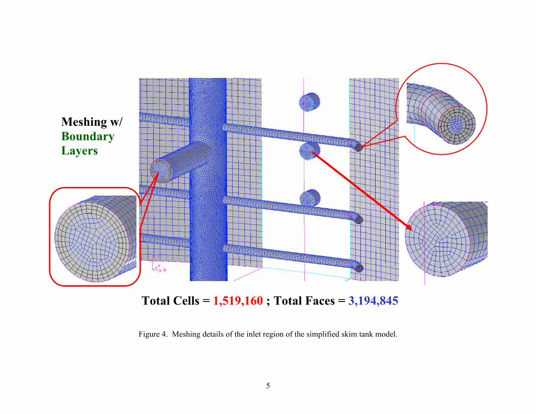
Figure 4. Meshing details of the inlet region of the simplified skim tank model.
Meshing w/ Boundary Layers
Total Cells = 1,519,160 ; Total Faces = 3,194,845

6
Meshing of the Flow Domain
For CFD, the computational approach differs from analytical (or theoretical) solutions in that the CFD software only solves equations at specific points rather than for the entire flow field. Properly choosing these points may become quite difficult - especially for a very complex geometry and sometimes it may require hundreds of thousands or millions of points. Before these specific points can be generated, the user must first determine the size of the region to be modeled -- this is the so-called “computational domain”. The computational meshing process breaks up the computational domain in space, then the calculations (solving the fundamental equations for mass, momentum and energy balance) are carried out at each node point simultaneously or sequentially, depending on the selected solver.
The quality of the grid is extremely important and can strongly influence the solution – sometimes also determining whether or not a valid or a converged solution can be achieved at all. The most important qualification about a computational meshing is that it must define enough points to capture everything of interest that is happening in the computational domain without becoming so extensive that unreasonable computation times are required. If there are too few points included, some of the critical information about the flow regime may be completely lost.
The types of meshing that arrange the spatial points in a roughly rectangular (or hexahedral) arrangement are referred to as "structured" meshing. Another method of mesh generation, which involves a triangular (or tetrahedral) layout of the computational points, is called "unstructured" meshing. Sometimes, different meshes can be adapted in different regions decomposed from the whole flow field to take advantage of specific characteristics of the different meshing systems. Such a combination is so-called “hybrid” meshing (also including prism/wedge and pyramid elements).
In this study, a hybrid meshing was constructed in the first stage of the study for the simplified skim tank model without the bulk volume between the large perforated plates. The hybrid meshing was comprised of 1,519,160 hybrid cells, and the total node count was 367,855 with 3,194,845 faces. As described previously and shown in Figure 4, the surface meshing of the inlet header and the laterals illustrates the details of the tighter meshing scheme implemented near the region of the inlet distributors. In the later stage of the study, a fully structured meshing was created including the bulk volume of the tank between the two large perforated plates and there are a total of 695,620 hexahedral cells with 730,041 nodes and 2,122,171 faces. The reduction of total cell count was due to the relatively loose meshing scheme and a further simplification of the inlet boundaries.

7
Material Properties
The CFD software used in this study is capable of simulating multiple phase flows of a computational domain with both structured or hybrid meshing. The fluids used in this study were produced water and its associated oil content of 710 mg/liter. Under the operating conditions, 35ºC and 101.3 kPa, the density of the produced water is 1104.3 kg/m3 and its viscosity is 0.7225 cP, whereas, the density and viscosity of the oil phase at operating conditions are 814.9 kg/m3 and 3.54 cP, respectively.
Simulation Models
In this study for skim tank design, two different CFD simulation models were employed. The following is the brief description of the two simulation models.
VOF (Volume of Fluid) Model: It is a multiphase model accepting simultaneous different fluid flows. However, the phases are not interpenetrating. The volume fraction of each phase within a computational cell is determined and used to volume-average the properties of the individual fluids. No particle sizes can be specified for the incoming phases and it is usually done with transient calculations with small time steps. This model was used in the first stage study focusing on the flow rate through the inlet distribution device.
Steady-State (Water Phase Only) Model: The Single-Phase Steady-State model is used to develop the flow regime below the water surface. There was a virtual barrier at the surface in order to generate realistic flow profiles for a totally water-filled tank model. Once the flow regime has been calculated in the steady-state model, particles can be injected at the inlet (or any other location of the operator’s choice) to visualize their movement within the flow field. The properties of the particles (size, density, etc.) can be chosen to simulate any of the phases being studied. Using this technique, it is possible to determine particle sizes likely to be carried out with the opposite phase as well as retention times of each phase within the skim tank.
Results and Discussions
Flow Rates of Inlet Distributor: The mass flow rates in the inlet distributor through each lateral at different simulation time from 100 to 120 seconds are listed in Table 1 and the corresponding plot is shown in Figure 5. The above flow rates were calculated during the first stage study using the VOF Model with transient simulation and a total simulation time of 120 seconds. Note that the variance in mass flow rates out of the laterals is less than ± 0.5%. This constitutes excellent flow distribution from the inlet distributor.

8
Table 1: Mass Flow Rates through Inlet Distributor Laterals
Distributor Time Flow Ratio Time Flow Ratio Time Flow Ratio Laterals 100 sec % 110 sec % 120 sec %
Arm-B1 25.234 12.55% 25.441 12.55% 25.390 12.54%
Arm-B2 24.401 12.14% 24.721 12.20% 24.785 12.24%
Arm-B3 24.684 12.28% 24.973 12.32% 25.019 12.36%
Arm-B4 26.301 13.08% 26.312 12.98% 26.141 12.91%
Arm-F1 25.280 12.58% 25.490 12.58% 25.442 12.57%
Arm-F2 24.316 12.10% 24.632 12.15% 24.690 12.20%
Arm-F3 24.525 12.20% 24.814 12.24% 24.860 12.28%
Arm-F4 26.278 13.07% 26.291 12.97% 26.122 12.90%
Summation 201.019 100.00% 202.674 100.00% 202.448 100.00%
Figure 5. Mass flow rates out of individual inlet distributor laterals.

9
Skim Tank Retention Time: Oil and water separation is fundamentally a gravity separation process. Almost any production facility can gain significant benefits from inclusion of a gravity separator in the primary stage of produced water treatment. However, the primary limitation of successful gravity separation is the size of the vessel required to provide adequate retention time for full treatment and the efficient use of available tank volume. In CFD simulations, produced water retention times were determined by injecting water “particles” into the model and tracking their time to exit the outlet nozzles. The results are shown in Figure 6 and Figure 7, in histogram plots and cumulative curves as a percentage of total particles exiting, for skim tank internals without the two large perforated plates and after the installation of the two large perforated plates. A comparison of the theoretical (volumetric displacement) retention times for produced water with the median retention times determined by CFD analysis also is shown in the table on the right-hand-side in both Figures 6 and 7. The theoretical retention time of the skim tank is 17,406 seconds based on a liquid level of 22.5 feet with a total produced water flow rate of 100,000 BBL/Day. As can be seen from the tables, water retention time for the skim tank without the two perforated plates was about 43.4% of the theoretical value. This is a clear indication that short circuiting occurs inside the skim tank. On the other hand, the retention time of produced water was improved to almost 88.5% of the theoretical value after installation of the two large perforated plates. Furthermore, minimum value of the retention time for the latter was 7434 seconds as compared to 634 seconds for the former case. These results suggested a significant improvement of effectively utilizing the bulk part of the tank volume when implementing the design and installation of the two large perforated plates.
Fluid Flow Patterns: As traced by the flow path-lines plots of the CFD software, the fluid flow paths, colored by retention time, inside the skim tank without and with the two large perforated plates are shown in Figures 8(a) and 8(b), respectively. In Figure 8(a), there are large swirling patterns that are characteristics of severe recirculation and the presence of short-circuiting flow paths inside the skim tank. In contrast, the path lines are improved in Figure 8(b) with a much reduced recirculation pattern. In separate simulations, the calculations showed similar flow patterns with a produced water flow rate of 30,000 BBL/Day and the skim tank liquid level set at 17 feet instead of the original 22.5 feet. The plots of flow path lines for those low flow simulations are illustrated in Figures 9 (a) and 9(b).
Carry-under of Oil droplets in Water Phase: In order to evaluate the separation performance of the skim tank with designed internals, the entrainment of oil droplets in the water phase was studied by the injection of various sizes of oil “particles” into the water phase at the inlet and then determining their potential for carry-under by following the particle tracks generated by the CFD

10
simulations. It should be noted that current CFD modeling is unable to simulate the coalescence of oil droplets over time. Therefore, the separation performance illustrated here is for the worst case scenario where the reverse emulsion is fully stabilized.
The CFD model used in these determinations was the single-phase steady-state model with a virtual barrier placed at the surface as previously described. The side view of the tank with particle tracking for 50 µm, 75 µm, and 100 µm oil droplets are shown in Figures 10, 11, and 12, respectively. Examination of these figures shows that there is substantial entrainment of the 50 µm oil droplets, only slight entrainment of the 75 µm oil droplets, and no entrainment of the 100 µm droplets. In summary, with the implementation of designed internals, the oil droplets of size larger than 100 microns are expected to be readily skimmed off without extra assistance from gas flotation inside the skim tank at a produced water flow rate of 100,000 BBL/Day. In a later study with a lower produced water flow rate of 30,000 BBL/Day and skim tank liquid level set at 17 feet, the minimum oil droplet size that was readily skimmed off was reduced to about 50 microns.
Conclusions
Computational fluid dynamics simulations were performed on a large diameter skim tank and the results indicate that a satisfactory performance of the tank can be achieved with the proposed internal configuration under the specified produced water flow rate provided that the incoming oil droplets are not too small and that bulk gas evolution in the inlet region is eliminated or minimized. With the installation of two large perforated plates, the “Median” value of the estimated retention time from particle tracking is 88.5% of the calculated theoretical retention time. This suggests a very effective utilization of the bulk part of the skim tank volume.
The results from transient CFD simulations demonstrate that an excellent flow distribution through the inlet distributor is achieved with the variance in mass flow rates out of each lateral being less than ± 0.5%. From the particle tracking results, the CFD model predicts that oil droplets larger than 100 microns are expected to be fully skimmed off without assistance from gas flotation at a produced water flow rate of 100,000 BBL/Day.

11
Figure 6. Retention time histogram and cumulative curve of skim tank without the two large perforated plates.
Full Tank Histogram (w/o 2 Perforated Plates)
0
20
40
60
80
100
120
0
3000
6000
9000
1200
0
1500
0
1800
0
2100
0
2400
0
2700
0
3000
0
3300
0
3600
0
3900
0
4200
0
4500
0
4800
0
5100
0
5400
0
5700
0
6000
0
6300
0
6600
0
6900
0
7200
0
7500
0
7800
0
8100
0
8400
0
8700
0
9000
0
9300
0
9600
0
9900
0
Retention Time (sec)
Freq
uenc
y
.%
10.%
20.%
30.%
40.%
50.%
60.%
70.%
80.%
90.%
100.%
FrequencyCumulative %

12
Figure 7. Retention time histogram and cumulative curve of skim tank with the two large perforated plates.
Full Tank Histogram (w/ 2 Perforated Plates)
0
10
20
30
40
50
60
030
0060
0090
0012
000
1500
018
000
2100
024
000
2700
030
000
3300
036
000
3900
042
000
4500
048
000
5100
054
000
5700
060
000
6300
066
000
6900
072
000
7500
078
000
8100
084
000
8700
090
000
9300
096
000
9900
0
Retention Time (sec)
Freq
uenc
y
0%
10%
20%
30%
40%
50%
60%
70%
80%
90%
100%
FrequencyCumulative %

13
(a)
(b)
Figure 8. Fluid flow path lines inside the skim tank (a) Without large perforated plates. (b) With two large perforated plates.

14
(a) (b)
Figure 9. Comparison of flow path lines under low flow rate of 30,000 BWPD and low liquid level at 17 feet.
(a) Skim tank without the large perforated plates. (b) Skim tank with two large perforated plates.

15
Figure 10. Particle tracking of oil droplets of 50 micron under designed flow rate.
Figure 11. Particle tracking of oil droplets of 75 micron under designed flow rate.
Side View
Particle Size = 50 micron
Side View
Particle Size = 75 micron

16
Figure 12. Particle tracking of oil droplets of 100 micron under designed flow rate.
Side View
Particle Size = 100 micron