Embed Size (px)
Citation preview
Energy and Power Engineering, 2012, 4, 365-371 http://dx.doi.org/10.4236/epe.2012.45048 Published Online September 2012 (http://www.SciRP.org/journal/epe)
The Density and Momentum Distributions of 2-Dimensional Transonic Flow in an LP-Steam Turbine
Aldo Antonio Rueda Martínez, Fernando Rueda Martínez, Miguel Toledo Velázquez, Florencio Sánchez Silva, Ignacio Carvajal Mariscal, Juan Abugaber Francis
Researching and Graduate Section, Applied Hydraulics and Thermal Engineering Laboratory, ESIME—Instituto Politécnico Nacional, Mexico City, Mexico
Email: [email protected]
Received June 5, 2012; revised July 7, 2012; accepted July 19, 2012
ABSTRACT
Within turbine blade rows, particularly for cascades of high deflection angle, cross-channel gradients of steam properties may be appreciable. To determine the effects on spontaneous condensation of gradients of supersaturation normal to streamlines, the conservation equations can be incorporated in a two dimensional calculation procedure. With the help of program FORTRAN 90 a developed computational program of calculations is accomplished, whose results are communicated to the pressure and Mach number distribution, direction of flow and streamlines in the field and the drops distribution in the outlet of the stator blade mesh. The procedure contains a program section, which avoids difficulties in the strongly curved profile of the leading and trailing edge by a developed computational mesh construction. Keywords: Steam Turbines; Nucleation; Two Phase Flow; Erosion
1. Introduction
Basically, there are two fundamental theories for two-phase flow, namely, the macroscopic continuum mechanics the-ory and the microscopic kinetic theory. At present, the most accurate and efficient manner to model the interaction between the moisture and the gas phase, is within a Lagrangian frame of reference. Interaction between the phases, in the present model, is through appropriately modeled interphase source terms.
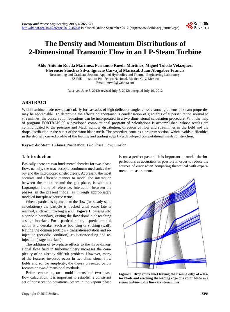
When a particle is injected into the flow (for steady-state calculations) the particle is tracked until some fate is reached, such as impacting a wall, Figure 1, passing into a periodic boundary, exiting the flow domain or reaching a stage interface. For a particular fate, a predetermined action is undertaken such as bouncing or sticking (wall), leaving the domain (outflow), translation/rotation and re- injection (periodic condition), collection/scaling and re- injection (stage interface).
The addition of two-phase effects to the three-dimen-sional flow field in turbomachinery increases the com-plexity of an already difficult problem. However, many of the features involved occur in two-dimensional flow fields and so, for simplicity, the theory presented below focuses on two-dimensional methods.
Before embarking on a multi-dimensional two phase flow calculation, it is important to establish a consistent set of conservation equations. Steam in the vapour phase
is not a perfect gas and it is important to model the im- perfections as accurately as possible in order to reduce the sources of error when comparing theoretical with experi-mental measurements.
Figure 1. Drop (pink line) leaving the trailing edge of a sta-tor blade and reaching the leading edge of a rotor blade in a steam turbine. Blue lines are streamlines.
Copyright © 2012 SciRes. EPE
A. A. RUEDA MARTÍNEZ ET AL. 366
When the codes combine Eulerian-Lagrangian frame of reference it means that the main flow equations are solved in an Eulerian framework (the program uses a conven-tional H-mesh) but the wetness calculation follow indi-vidual fluid particles through the cascades. For steady- flow, this involves identifying the true streamlines through the cascades in order to interpolate the pressure time variation required for the wetness calculation.
The ultimate objective is to develop a computer model of a wet steam turbine which will provide estimates for all the main effects of wetness including changes in the flow aerodynamics, the wetness loss distribution and even the potential for erosion damage.
2. Methodology
2.1. Two Phase Flow: Fog Droplet Deposition and Coarse Water Formation
What we known about the formation and movement of coarse water in steam turbines (and its effect on turbine efficiency), is that the mechanism responsible for fog dro- plet deposition onto the turbine blading is originated es-sentially by two methods: inertial impaction in which fog droplets are transported to the blade surfaces and is a lam- inar flow phenomenon caused by the inability of the dro- plets to follow precisely the vapour stream lines during their passage through a blade row. The second is deposi-tion by turbulent diffusion and occurs because very small droplets have a tendency to be transported through a tur-bulent boundary layer to a solid surface.
Coarse water appears as a result of the accumulation of fog droplets that come into contact with, and adhere to, the blade/casing surfaces. This coarse water flow contin-ues to build-up in passing through the machine as the steam continues to expand to lower pressures, at increased “equi-librium” wetness level, with more fog production and depo-sition. The effects of wetness, resulting from water for-mation and distribution, on both fluid dynamics and plant thermodynamics includes: the worsening of stage efficien-cies and the degrading effect on overall cycle performance.
Wetness loss, affecting both stage efficiency and tur-bine performance, is considered to be caused by several effects, initially by supersaturation and nucleation, fol-lowed by the moisture losses of droplet drag and inci-dence/centrifuging on rotor blades The total wetness frac-tion, at a point between blade rows in a turbine, can be considered to be the sum of contributions from fog (un-deposited) droplets, coarse droplets and coarse water flow-ing on hub or casing surfaces. The coarse droplet contri-bution can be measured by capture on absorbent material in suitably designed probes, with collection efficiencies greater than 90 percent for droplets larger than about 10 µm [1].
Erosion at the tip-inlet region of LP (Low Pressure)
moving blades is seen as the major mechanical problem of steam turbine operation in wet-steam. In essence, steam expanding in a LP turbine into the wet region, initially contains a fog of sub-micron drops. Some of the fog is deposited on fixed and moving blade surfaces and a high proportion of the resultant water is successively re-en- trained and deposited downstream, while further deposi-tion of fog droplets occurs on later stages. The water de-posited on the moving blades is centrifuged towards the outer casing, whereas that deposited on the fixed blades moves across and along their surfaces under the action of steam forces. Water eventually leaves the trailing edges of the fixed blades to form a distribution of drops typically up to 350 µm in diameter. These are only slowly acceler-ated by the steam and therefore impinge onto the leading- edge of the moving blade at an off-design incident trajec- tory-angle, and higher relative velocity, than the steam [2].
This in general, causes the familiar erosion of LP blades at the tip where relative velocities are high and water is concentrated by centrifugal effects.
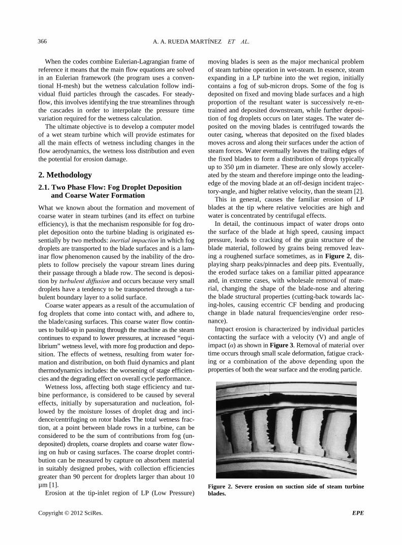
In detail, the continuous impact of water drops onto the surface of the blade at high speed, causing impact pressure, leads to cracking of the grain structure of the blade material, followed by grains being removed leav-ing a roughened surface sometimes, as in Figure 2, dis-playing sharp peaks/pinnacles and deep pits. Eventually, the eroded surface takes on a familiar pitted appearance and, in extreme cases, with wholesale removal of mate-rial, changing the shape of the blade-nose and altering the blade structural properties (cutting-back towards lac-ing-holes, causing eccentric CF bending and producing change in blade natural frequencies/engine order reso-nance).
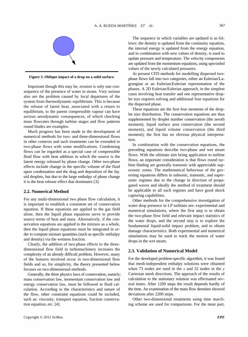
Impact erosion is characterized by individual particles contacting the surface with a velocity (V) and angle of impact (α) as shown in Figure 3. Removal of material over time occurs through small scale deformation, fatigue crack- ing or a combination of the above depending upon the properties of both the wear surface and the eroding particle.
Figure 2. Severe erosion on suction side of steam turbine blades.
Copyright © 2012 SciRes. EPE
A. A. RUEDA MARTÍNEZ ET AL. 367
Figure 3. Oblique impact of a drop on a solid surface.
Important though this may be, erosion is only one con- sequence of the presence of water in steam. Very serious also are the problem caused by local departures of the system from thermodynamic equilibrium. This is because the release of latent heat, associated with a return to equilibrium, to the parent compressible vapour can have serious aerodynamic consequences, of which chocking mass flowrates through turbine stages and flow patterns round blades are examples.
Much progress has been made in the development of numerical methods for two- and three-dimensional flows in other contexts and such treatments can be extended to two-phase flows with some modifications. Condensing flows can be regarded as a special case of compressible fluid flow with heat addition in which the source is the latent energy released by phase change. Other two-phase effects include change in the specific volume of the fluid upon condensation and the drag and deposition of the liq-uid droplets, but due to the large enthalpy of phase change it is the heat release effect that dominates [3].
2.2. Numerical Method
For any multi-dimensional two phase flow calculation, it is important to establish a consistent set of conservation equation. If these equations are applied to the gas field alone, then the liquid phase equations serve to provide source terms of heat and mass. Alternatively, if the con-servation equations are applied to the mixture as a whole, then the liquid phase equations must be integrated in or-der to compute mixture quantities (such as specific enthalpy and density) via the wetness fraction.
Clearly, the addition of two-phase effects to the three- dimensional flow field in turbomachinery increases the complexity of an already difficult problem. However, many of the features involved occur in two-dimensional flow fields and so, for simplicity, the theory presented below focuses on two-dimensional methods.
Generally, the three physics laws of conservation, namely: mass conservation law, momentum conservation law and energy conservation law, must be followed in fluid cal-culation. According to the characteristics and nature of the flow, other constraint equations could be included, such as: viscosity, transport equation, fraction conserva-tion equation, etc. [4].
The sequence in which variables are updated is as fol-lows: the density is updated from the continuity equation, the internal energy is updated from the energy equation, and in combination with new values of density, is used to update pressure and temperature. The velocity components are updated from the momentum equations, using upwinded values of the newly calculated pressures.
At present CFD methods for modelling dispersed two- phase flows fall into two categories, either an Eulerian/La- grangian or an Eulerian/Eulerian representation of the phases. A 2D Eulerian/Eulerian approach, in the simplest cases involving heat transfer and one representative drop-let size requires solving and additional four equations for the dispersed phase.
These equations are the first four moments of the drop-let size distribution. The conservation equations are thus supplemented by droplet number conservation (the zeroth moment), liquid surface area conservation (the second moment), and liquid volume conservation (the third moment); the first has no obvious physical interpreta- tion.
In combination with the conservation equations, the preceding equations describe two-phase and wet steam flows. With the ultimate aim being application to turbine flows, an important consideration is that flows round tur-bine blading are generally transonic with appreciable sup- ersonic zones. The mathematical behaviour of the gov-erning equations differs in subsonic, transonic, and super-sonic regimes due to the change in direction of propa-gated waves and ideally the method of treatment should be applicable to all such regimes and have good shock capturing capabilities.
Other methods for the comprehensive investigation of water drop presence in LP turbines are: experimental and numerical simulations, where the first step is to obtain the two-phase flow field and relevant impact statistics of the water drops, and the second step is to explore the fundamental liquid-solid impact problem, and to obtain damage characteristics. Both experimental and numerical simulations may be used to track the motion of water drops in the wet steam.
2.3. Validation of Numerical Model
For the developed problem-specific algorithm, it was found that mesh-independent enthalpy solutions were obtained when 73 nodes are used in the x and 32 nodes in the y Cartesian mesh directions. The approach of the results of calculation to the stationary solution was effectuated sev-eral times. After 1200 steps the result depends hardly of the time. An examination of the mass flow densities showed deviations after 2200 steps.
Other two-dimensional treatments using time march-ing scheme are used for comparisons. For the most part,
Copyright © 2012 SciRes. EPE
A. A. RUEDA MARTÍNEZ ET AL. 368
the methods have been applied to blade-to-blade flows. Calculations in the meridional plane have also been un-dertaken, however, using a time marching method, and using streamline curvature.
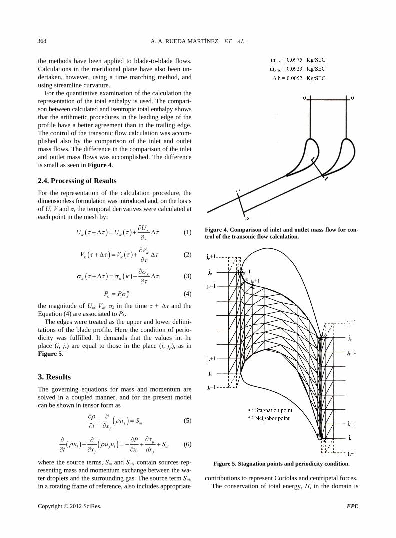
For the quantitative examination of the calculation the representation of the total enthalpy is used. The compari-son between calculated and isentropic total enthalpy shows that the arithmetic procedures in the leading edge of the profile have a better agreement than in the trailing edge. The control of the transonic flow calculation was accom-plished also by the comparison of the inlet and outlet mass flows. The difference in the comparison of the inlet and outlet mass flows was accomplished. The difference is small as seen in Figure 4.
2.4. Processing of Results
For the representation of the calculation procedure, the dimensionless formulation was introduced and, on the basis of U, V and σ, the temporal derivatives were calculated at each point in the mesh by:
U
U U
(1)
VV V
(2)
1nP P
(3)
(4)
the magnitude of Uk, Vk, k in the time + and the Equation (4) are associated to Pk.
The edges were treated as the upper and lower delimi-tations of the blade profile. Here the condition of perio-dicity was fulfilled. It demands that the values int he place (i, js) are equal to those in the place (i, jp), as in Figure 5.
3. Results
The governing equations for mass and momentum are solved in a coupled manner, and for the present model can be shown in tensor form as
j mj
u S
t x (5)
ijui
j i j
PS
x dx
i j iu u u
t x
(6)
where the source terms, Sm and Sui, contain sources rep-resenting mass and momentum exchange between the wa-ter droplets and the surrounding gas. The source term Sui, in a rotating frame of reference, also includes appropriate
Figure 4. Comparison of inlet and outlet mass flow for con-trol of the transonic flow calculation.
Figure 5. Stagnation points and periodicity condition.
contributions to represent Coriolas and centripetal forces. The conservation of total energy, H, in the domain is
Copyright © 2012 SciRes. EPE
A. A. RUEDA MARTÍNEZ ET AL. 369
governed by the conservation equation
jj i ij h
ii j
qPH u H
t t x x
u S
x
(7)
where
12 i iu u H h
The solutions based on these equations for two-phase flows when used in combination with H-grids, show some smearing pressure rises but by using a more orthogonal grid the problems can be minimized. The use of higher order schemes and more sophisticated grids reduce the problems still further. Consequently, the use of these meth-ods in the examination of two phase flows in turbines can be recommended with some confidence.
Numerical results demonstrate that wet steam flows oc- curring in turbine passages exhibit features which are absent in single phase. The dominant effect of phase change in high speed condensing flows is the local departures from thermodynamic equilibrium and sudden release of heat when the system subsequently recovers it.
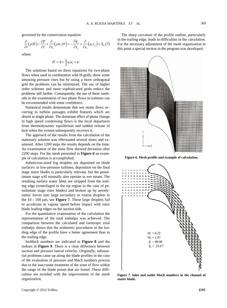
The approach of the results from the calculation of the stationary solution was effectuated several times and ex-amined. After 1200 steps the results depends on the time. An examination of the mass flow showed deviation after 2200 steps. For the mesh presented in Figure 6 an exam-ple of calculation is accomplished.
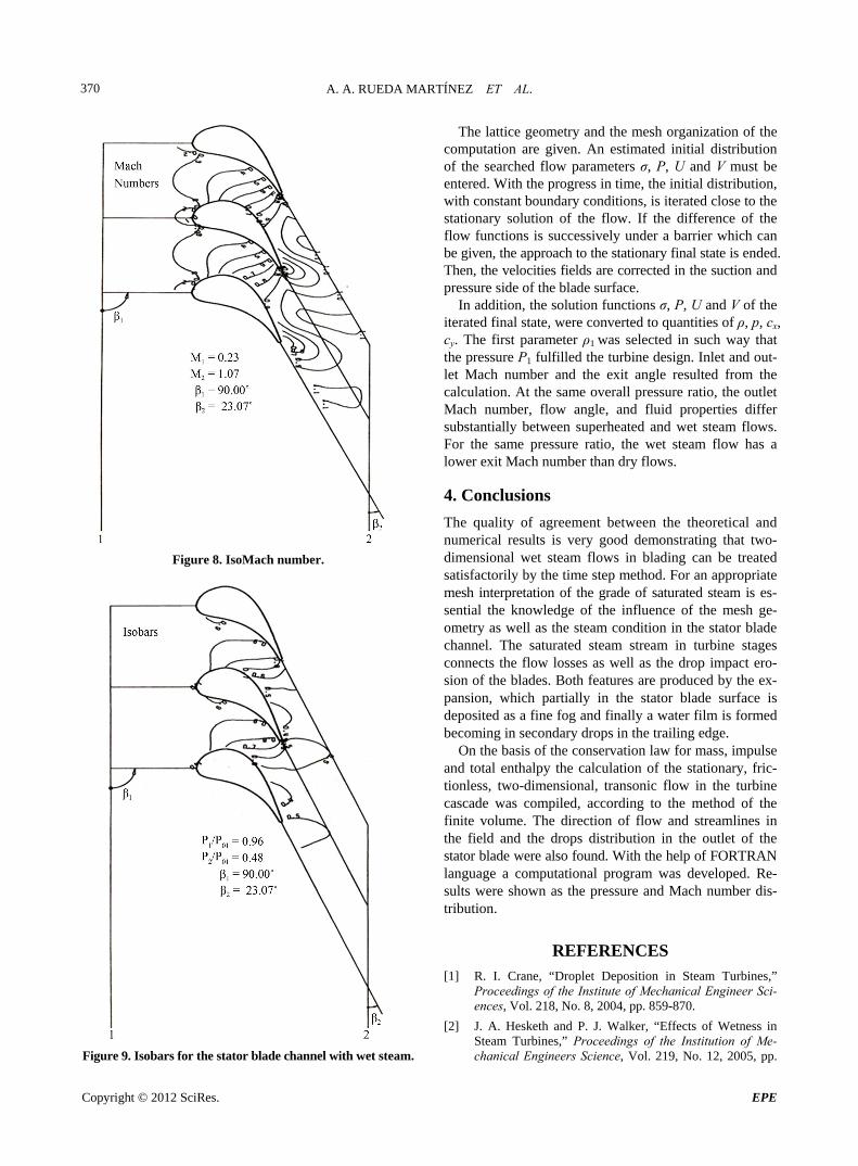
Submicron-sized fog droplets are deposited on blade surfaces: in low-pressure turbines, deposition on the final stage stator blades is particularly relevant, but the penul-timate stage will normally also operate in wet steam. The resulting surface water films are stripped from the trail-ing edge (centrifuged to the rip region in the case of pe-nultimate stage rotor blades) and broken up by aerody-namic forces into large secondary or coarse droplets in the 10 - 100 µm, see Figure 7. These large droplets fail to accelerate to vapour speed before impact with rotor blade leading edges on the suction side.
For the quantitative examination of the calculation the representation of the total enthalpy was achieved. The comparison between the calculated and isentropic total enthalpy shows that the arithmetic procedures in the lea- ding edge of the profile have a better agreement than in the trailing edge.
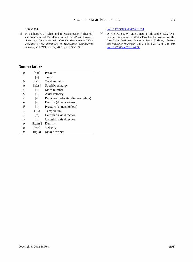
IsoMach numbers are indicated in Figure 8 and the isobars in Figure 9. There is a clear difference between suction and pressure lateral velocity. Originally, substan-tial problems came up along the blade profiles in the case of the evaluation of pressure and Mach numbers process due to the inaccurate treatment of the zone of flow within the range of the blade points that are found. These diffi-culties are avoided with the improvement of the mesh organization.
The sharp curvature of the profile outline, particularly in the trailing edge, leads to difficulties in the calculation. For the necessary adjustment of the mesh organization in this point a special section in the program was developed.
Figure 6. Mesh profile and example of calculation.
Figure 7. Inlet and outlet Mach numbers in the channel of stator blade.
Copyright © 2012 SciRes. EPE
A. A. RUEDA MARTÍNEZ ET AL. 370
Figure 8. IsoMach number.
Figure 9. Isobars for the stator blade channel with wet steam.
The lattice geometry and the mesh organization of the computation are given. An estimated initial distribution of the searched flow parameters σ, P, U and V must be entered. With the progress in time, the initial distribution, with constant boundary conditions, is iterated close to the stationary solution of the flow. If the difference of the flow functions is successively under a barrier which can be given, the approach to the stationary final state is ended. Then, the velocities fields are corrected in the suction and pressure side of the blade surface.
In addition, the solution functions σ, P, U and V of the iterated final state, were converted to quantities of ρ, p, cx, cy. The first parameter ρ1 was selected in such way that the pressure P1 fulfilled the turbine design. Inlet and out-let Mach number and the exit angle resulted from the calculation. At the same overall pressure ratio, the outlet Mach number, flow angle, and fluid properties differ substantially between superheated and wet steam flows. For the same pressure ratio, the wet steam flow has a lower exit Mach number than dry flows.
4. Conclusions
The quality of agreement between the theoretical and numerical results is very good demonstrating that two- dimensional wet steam flows in blading can be treated satisfactorily by the time step method. For an appropriate mesh interpretation of the grade of saturated steam is es-sential the knowledge of the influence of the mesh ge-ometry as well as the steam condition in the stator blade channel. The saturated steam stream in turbine stages connects the flow losses as well as the drop impact ero-sion of the blades. Both features are produced by the ex-pansion, which partially in the stator blade surface is deposited as a fine fog and finally a water film is formed becoming in secondary drops in the trailing edge.
On the basis of the conservation law for mass, impulse and total enthalpy the calculation of the stationary, fric-tionless, two-dimensional, transonic flow in the turbine cascade was compiled, according to the method of the finite volume. The direction of flow and streamlines in the field and the drops distribution in the outlet of the stator blade were also found. With the help of FORTRAN language a computational program was developed. Re-sults were shown as the pressure and Mach number dis-tribution.
REFERENCES [1] R. I. Crane, “Droplet Deposition in Steam Turbines,”
Proceedings of the Institute of Mechanical Engineer Sci-ences, Vol. 218, No. 8, 2004, pp. 859-870.
[2] J. A. Hesketh and P. J. Walker, “Effects of Wetness in Steam Turbines,” Proceedings of the Institution of Me-chanical Engineers Science, Vol. 219, No. 12, 2005, pp.
Copyright © 2012 SciRes. EPE
A. A. RUEDA MARTÍNEZ ET AL.
Copyright © 2012 SciRes. EPE
371
1301-1314.
[3] F. Bakhtar, A. J. White and H. Mashmoushy, “Theoreti- cal Treatments of Two-Dimensional Two-Phase Flows of Steam and Comparison with Cascade Measurement,” Pro- ceedings of the Institution of Mechanical Engineering Science, Vol. 219, No. 12, 2005, pp. 1335-1336.
doi:10.1243/095440605X31454
[4] D. Xie, X. Yu, W. Li, Y. Hou, Y. Shi and S. Cai, “Nu-merical Simulation of Water Droplets Deposition on the Last Stage Stationary Blade of Steam Turbine,” Energy and Power Engineering, Vol. 2, No. 4, 2010. pp. 248-249. doi:10.4236/epe.2010.24036
Nomenclature
p [bar] Pressure τ [s] Time H [kJ] Total enthalpy h [kJ/s] Specific enthalpy M [-] Mach number U [-] Axial velocity V [-] Peripheral velocity (dimensionless)σ [-] Density (dimensionless) P [-] Pressure (dimensionless) T [˚C] Temperature x [m] Cartesian axis direction y [m] Cartesian axis direction ρ [kg/m3] Density u [m/s] Velocity m [kg/s] Mass flow rate


![Linear Momentum Density in Quasistatic Electromagnetic Systems · arXiv:physics/0404139v1 [physics.ed-ph] 29 Apr 2004 Linear Momentum Density in Quasistatic Electromagnetic Systems](https://img.pdfslide.us/doc/110x75/5e00efafeeb98575462d5f23/linear-momentum-density-in-quasistatic-electromagnetic-systems-arxivphysics0404139v1.jpg)