Embed Size (px)
Citation preview
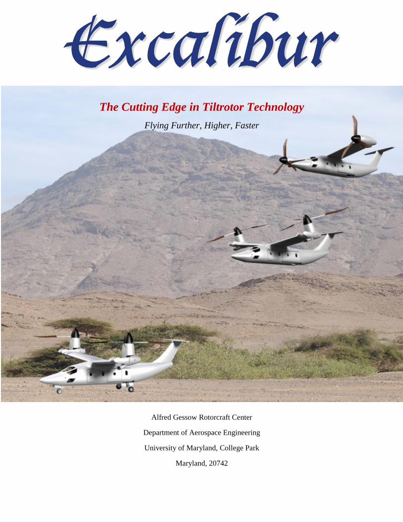
The Cutting Edge in Tiltrotor Technology
Flying Further, Higher, Faster
Alfred Gessow Rotorcraft Center
Department of Aerospace Engineering
University of Maryland, College Park
Maryland, 20742
I
Acknowledgements
The Excalibur design team would like to thank those who took the time to assist us in the 2011
Design Competition.
Professors:
Dr. Vengalattore T. Nagaraj – Senior Research Scientist, Dept. of Aerospace Engineering,
University of Maryland, College Park.
Dr. Inderjit Chopra – Gessow Professor, Director of Gessow Rotorcraft Center (AGRC)
Professor, Dept. of Aerospace Engineering, University of Maryland, College Park.
Dr. J. Gordon Leishman – Minta Martin Professor of Engineering, Dept. of Aerospace
Engineering, University of Maryland, College Park.
Dr. Omri Rand – Shirley and Burt Harris Academic Chair, Technion Israel Institute of
Technology, Technion City, Haifa, Israel.
Industry Professionals:
Charley Kilmain – Director, Rotor and Drive System Design, Bell Helicopter Textron, Inc., Fort
Worth, Texas.
Dr. Kenneth Rosen – Aero-Science Technology Associates LLC, Guilford, Connecticut.
Dr. Wayne Johnson – Alexander A. Nikolsky Honorary Lecturer, NASA Ames Research Center,
Moffett Field, California.
Mr. Matthew Tarascio – Advanced Concepts, Sikorsky Innovation Lead, Sikorsky Aircraft
Corporation, Stratford, Connecticut.
Dr. Gaurav Gopalan – Assistant Research Scientist, University of Maryland.
Mr. Cyrus Abdolah – Flight Simulation and Controls Engineer, Emerald Sky Technologies, LLC.
Mr. Tony Lambregts – FAA Chief Scientific and Technical Advisor, Flight Guidance and Control.
Mr. Nizar Bechara, ATP – Chief Pilot/Instructor, Royal Air Flight LLC, Columbia, Maryland.
Fellow Graduate Students:
A special thanks goes to Conor Stahlhut for his expertise in propeller aerodynamics
Bharath Govindarajan, Moble Benedict, Ananth Sridharan, Benjamin Berry, Graham Bowen-
Davies, and Joeseph Schmaus.

II
Table of Contents TABLE OF FIGURES ............................................................................................................... VI
LIST OF TABLES ................................................................................................................... VIII
RFP REQUIREMENTS AND COMPLIANCE ...................................................................... IX
PROPOSAL SUMMARY ............................................................................................................. 1
CONCEPT DESIGN ..................................................................................................................... 1
1 INTRODUCTION ................................................................................................................. 9
2 VEHICLE CONFIGURATION AND SELECTION ......................................................... 9
2.1 MISSION REQUIREMENTS ....................................................................................................... 9
2.2 EXAMINATION OF DIFFERENT CONFIGURATIONS................................................................. 10
2.2.1 Conventional Helicopters ............................................................................................. 10
2.2.2 Compound Helicopters ................................................................................................. 11
2.2.3 Tandem Rotor Helicopters ........................................................................................... 11
2.2.4 Convertible Rotor Aircraft ........................................................................................... 12
2.3 ANALYTICAL HIERARCHY PROCESS AND HOUSE OF QUALITY ............................................ 13
3 PRELIMINARY TILTROTOR SIZING .......................................................................... 16
3.1 DESCRIPTION OF THE ALGORITHM ....................................................................................... 16
3.2 IDENTIFICATION OF THE SIZING MISSION ............................................................................. 18
3.3 PARAMETRIC STUDIES .......................................................................................................... 19
3.3.1 Selection of Disk Loading (Hover) ............................................................................... 19
3.3.2 Selection of Blade Aspect Ratio (Hover) ...................................................................... 20
3.3.3 Selection of Number of Blades...................................................................................... 21
3.3.4 Selection of Tip Speed (Hover) ..................................................................................... 22
3.3.5 Selection of Blade Loading (BL), CT/ ......................................................................... 22
3.3.6 Selection of Wing Parameters ...................................................................................... 23
3.3.8 High Lift Devices and Download Control .................................................................... 24
3.3.9 Empennage Sizing (Horizontal and Vertical Tail Sizing) ............................................. 24
3.3.10 Engine Sizing ................................................................................................................ 25
4 EXCALIBUR DESIGN FEATURES/ PERFORMANCE SUMMARY ........................ 27
5 PROPROTOR AND HUB DESIGN .................................................................................. 28
5.1 VARIABLE DIAMETER ROTOR .............................................................................................. 28
5.1.1 Diameter ....................................................................................................................... 28
5.1.2 Tip Speed ...................................................................................................................... 28
5.1.3 Solidity .......................................................................................................................... 29
5.1.4 Blade Twist and Taper .................................................................................................. 30
5.1.5 Blade Design ................................................................................................................ 32
III
5.1.6 Airfoil Sections ............................................................................................................. 32
5.2 BLADE STRUCTURAL DESIGN ............................................................................................... 33
5.2.1 Overview ....................................................................................................................... 33
5.2.2 Inner Segment and Strap .............................................................................................. 34
5.2.3 Outer Segment .............................................................................................................. 34
5.2.4 Blade Overlap and Locking .......................................................................................... 35
5.2.5 Load Path ..................................................................................................................... 35
5.2.6 Methods of Retraction and Extension ........................................................................... 36
5.2.7 Electric Motor Requirements........................................................................................ 37
5.2.8 Strap Sizing ................................................................................................................... 38
5.3 HUB DESIGN ......................................................................................................................... 39
5.3.1 Spool Drum ................................................................................................................... 39
5.3.2 Flexbeam ...................................................................................................................... 40
5.3.3 Bearing Assembly ......................................................................................................... 40
5.3.4 Solenoid Assembly ........................................................................................................ 40
5.3.5 Gimbaled Hub .............................................................................................................. 41
5.3.6 Aeroelastic Analysis ..................................................................................................... 42
6 DRIVETRAIN ..................................................................................................................... 43
6.1 EXISTING DRIVETRAIN DESIGNS .......................................................................................... 43
6.2 TRADE STUDIES .................................................................................................................... 44
6.3 EXCALIBUR DRIVETRAIN OVERVIEW .................................................................................... 46
6.4 DRIVETRAIN DESCRIPTION ................................................................................................... 46
6.4.1 UMD Turboshaft Engines ............................................................................................. 46
6.4.2 Auxiliary Power Unit .................................................................................................... 47
6.4.3 OEM Engine Gearboxes ............................................................................................... 47
6.4.4 Overrunning Clutch ...................................................................................................... 47
6.4.5 Interconnecting Driveshaft ........................................................................................... 47
6.4.6 Planetary Transmission ................................................................................................ 48
6.5 LUBRICATION AND COOLING ................................................................................................ 48
6.6 ALTERNATOR ........................................................................................................................ 49
7 AIRFRAME DESIGN ......................................................................................................... 49
7.1.1 Wing Structure .............................................................................................................. 49
7.1.2 Fuselage Structure ........................................................................................................ 50
7.1.3 Cabin Layout ................................................................................................................ 50
7.2 STRUCTURAL MATERIALS .................................................................................................... 51
7.3 LANDING GEAR .................................................................................................................... 53
IV
7.3.1 Longitudinal Tip-Over Criteria .................................................................................... 53
7.3.2 Lateral Tip-Over Criteria ............................................................................................. 53
7.3.3 Ground Clearance Criteria .......................................................................................... 54
8 AVIONICS ........................................................................................................................... 54
8.1 COCKPIT LAYOUT ................................................................................................................. 54
8.1.1 Flight Displays/Pilot Interface ..................................................................................... 54
8.1.2 Communications System ............................................................................................... 55
8.1.3 Avionics Sensors ........................................................................................................... 56
8.2 HEALTH AND USAGE MONITORING ...................................................................................... 56
8.2.1 Health Monitoring ........................................................................................................ 56
8.2.2 Usage Monitoring ......................................................................................................... 57
8.2.3 Maintenance Interface .................................................................................................. 57
9 FLIGHT CONTROL SYSTEM ......................................................................................... 57
9.1 CONTROL MIXING ................................................................................................................ 57
9.2 DYNAMICS AND STABILITY .................................................................................................. 59
9.2.1 Stability in Helicopter Mode ........................................................................................ 60
9.2.2 Stability in Airplane Mode ............................................................................................ 60
9.3 HANDLING QUALITIES .......................................................................................................... 61
9.4 FLY-BY-WIRE ARCHITECTURE ............................................................................................. 62
10 MULTI-MISSION CAPABILITY ..................................................................................... 64
10.1 DESIGNED FOR VERSATILITY ............................................................................................... 64
10.2 SEARCH AND RESCUE MISSION ............................................................................................ 64
10.3 INSERTION MISSION .............................................................................................................. 66
10.4 RESUPPLY MISSION .............................................................................................................. 67
11 WEIGHT ANALYSIS ......................................................................................................... 68
12 PERFORMANCE ANALYSIS .......................................................................................... 69
12.1 DRAG ESTIMATION ............................................................................................................... 69
12.2 VEHICLE DOWNLOAD ........................................................................................................... 71
12.3 HOVER PERFORMANCE ......................................................................................................... 72
12.4 FORWARD FLIGHT PERFORMANCE ....................................................................................... 73
12.5 CONVENTIONAL AIRPLANE TAKEOFF/LANDING .................................................................. 76
12.6 BROWNOUT SIGNATURE STUDIES ........................................................................................ 76
12.7 AUTOROTATIVE INDEX ......................................................................................................... 77
13 ACOUSTICS ........................................................................................................................ 77
13.1 INTERNAL NOISE .................................................................................................................. 77
13.2 EFFECTIVE PERCEIVED NOISE LEVEL ................................................................................... 78
V
14 SURVIVABILITY ............................................................................................................... 80
14.1 SUSCEPTIBILITY .................................................................................................................... 80
14.2 VULNERABILITY ................................................................................................................... 80
14.3 RECOVERABILITY ................................................................................................................. 80
14.4 CRASHWORTHY SEAT DESIGN .............................................................................................. 81
14.4.1 Variable Load Energy Absorber................................................................................... 81
14.4.2 Vibration Isolation ........................................................................................................ 81
14.5 AUTOROTATIVE INDEX ......................................................................................................... 82
14.6 ASSESSMENT OF FAILURE MODES ........................................................................................ 83
15 PROJECT DEVELOPMENT TIMELINE ....................................................................... 83
15.1 LIFE-CYCLE COST ANALYSIS ............................................................................................... 83
15.1.1 Direct Operating Cost (DOC) ...................................................................................... 85
15.1.2 Indirect Operating Cost (IOC) ..................................................................................... 86
15.2 TECHNOLOGY DEVELOPMENT PROGRAM ............................................................................ 87
15.3 PROJECT DEVELOPMENT ...................................................................................................... 88
16 SUMMARY .......................................................................................................................... 89
17 REFERENCES .................................................................................................................... 91
17.1 SECTION 1 ............................................................................................................................. 91
17.2 SECTION 2 ............................................................................................................................. 91
17.3 SECTION 3 ............................................................................................................................. 91
17.4 SECTION 4 ............................................................................................................................. 91
17.5 SECTION 5 ............................................................................................................................. 91
17.6 SECTION 6 ............................................................................................................................. 92
17.7 SECTION 7 ............................................................................................................................. 92
17.8 SECTION 8 ............................................................................................................................. 93
17.9 SECTION 9 ............................................................................................................................. 93
17.10 SECTION 10 ....................................................................................................................... 93
17.11 SECTION 11 ....................................................................................................................... 93
17.12 SECTION 12 ....................................................................................................................... 93
17.13 SECTION 13 ....................................................................................................................... 94
17.14 SECTION 14 ....................................................................................................................... 94
17.15 SECTION 15 ....................................................................................................................... 94
VI
Table of Figures Figure 2.1: a) Sikorsky X-2 and b) Eurocopter X3 compound helicopter technology demonstrators
....................................................................................................................................................... 11 Figure 2.2: CH-47 tandem rotor helicopter ................................................................................... 12 Figure 2.3: Relative Importance of customer evaluation criteria .................................................. 14 Figure 2.4: Spider diagram representing the relative benefits of one configuration of rotorcraft
over another ................................................................................................................................... 14 Figure 3.1: Block diagram of initial sizing code ........................................................................... 17 Figure 3.2: Blade aspect ratio versus a) maximum takeoff b) maximum takeoff power for the
three missions ................................................................................................................................ 19 Figure 3.3: Rotor diameter vs maximum take-off weight ............................................................. 19 Figure 3.4: Maximum take-off power vs disk loading .................................................................. 20 Figure 3.5: Effect of aspect ratio on a) fuel weight and b) max take-off weight ........................... 21 Figure 3.6: Variation of a) maximum take-off weight and b) power required versus number of
blades ............................................................................................................................................. 21 Figure 3.7: Variations in a) takeoff power and b) blade loading with tip speed ........................... 22 Figure 3.8: Final selection ............................................................................................................. 23 Figure 3.9: Engine takeoff power ratio for different pressure ratio values .................................... 25 Figure 3.10: Specific power against maximum continuous power for different engines .............. 26 Figure 5.1: Propulsive efficiency versus forward flight speed. A reduction in proprotor diameter
greatly increases the propulsive efficiency. ................................................................................... 28 Figure 5.2: Historical results of blade loading coefficient versus MGTOW at sea level (left) and
6000 ft 95º F (right) ....................................................................................................................... 29 Figure 5.3: Comparison of blade loading coefficient for varying blade aspect ratios and number
of proprotor blades. ........................................................................................................................ 29 Figure 5.4: Distribution of twist, taper and sweep on the proprotor blade. ................................... 30 Figure 5.5: Pareto frontier for the current design, showing the tradeoffs between optimization for
forward flight and hovering efficiency .......................................................................................... 32 Figure 5.6: Proprotor planform and airfoil selection ..................................................................... 33 Figure 5.7: Rapid prototyped linear blade twist retraction proof of concept ................................. 34 Figure 5.8: Exploded view of the interior design of the blade ...................................................... 35 Figure 5.9: Centrifugal force distributions .................................................................................... 36 Figure 5.10: Required servo torque for VDR actuation................................................................. 38 Figure 5.11: Close up of spool drum ............................................................................................. 39 Figure 5.12: Harmonic® Drive ...................................................................................................... 39 Figure 5.13: Pitch bearing and solenoid assembly ........................................................................ 41 Figure 5.14: Exploded view of homo-kinetic gimbaled hub ......................................................... 41 Figure 5.15: Fan plots for the proprotor in a) helicopter mode b) airplane mode ......................... 43 Figure 6.1: Conceptual configuration of Excalibur with wing tip mounted engines..................... 45 Figure 6.2: Conceptual configuration with rear mounted engines ................................................. 46 Figure 6.3: Engine power versus pressure altitude ....................................................................... 47 Figure 6.4: Two stage planetary transmission layout .................................................................... 48 Figure 7.1: Advanced composite wing structure (shown without flaps / flaperons) ..................... 50 Figure 7.2. Diagram of Ground Clearance Criteria ...................................................................... 54 Figure 8.1: Cockpit Displays and Avionics ................................................................................... 55 Figure 9.1: Control mixing strategy in hover ................................................................................ 58 Figure 9.2: Rotational Throttle Interface shown in 90o helicopter and 0o fixed wing configuration
(Rozovski, 2008)4 .......................................................................................................................... 59
VII
Figure 9.3: Pole Diagram Characterizing Hover Stability Modes ................................................. 60 Figure 9.4: Pole Diagram Characterizing Forward Flight Stability Modes ................................... 61 Figure 9.5: Simplified Representation of MIMO Controller ......................................................... 62 Figure 9.6: Fly-by-wire and control system architecture ............................................................... 63 Figure 10.1: Universal attachment fitting left) cargo restraint right) seat/litter post attachment .. 64 Figure 10.2: Typical search and rescue mission showing Excalibur’s speed, flight time, and range
capabilities. .................................................................................................................................... 65 Figure 10.3: Insertion mission profile showing Excalibur’s speed, flight time, and range
capabilities ..................................................................................................................................... 66 Figure 10.4: Typical resupply mission showing Excalibur’s speed, flight time, and range
capabilities ..................................................................................................................................... 67 Figure 11.1: Longitudinal CG travel charts for a) all three missions b) resupply mission ............ 69 Figure 12.1: Fuselage cross-sectional cuts .................................................................................... 70 Figure 12.2: HOGE power required and power available at MGTOW versus altitude ................. 72 Figure 12.3: Weight - altitude - temperature curves ...................................................................... 73 Figure 12.4: Power required versus forward flight speed at MGTOW. ........................................ 73 Figure 12.5: Fuel flow versus forward flight speed at MGTOW .................................................. 74 Figure 13.1: Three-dimensional representations of the sound pressure levels in hover ................ 78 Figure 13.2: Three dimensional representations of the sound pressure levels in airplane mode... 79 Figure 14.1: Adjustable roller pin and wire bender VLEA and corresponding limit load
adjustment setting .......................................................................................................................... 81 Figure 14.2: Comparison of autorotative index for different rotorcraft ........................................ 82 Figure 15.1: Breakdown of direct operating cost .......................................................................... 85 Figure 15.2: Breakdown of indirect operating costs ...................................................................... 86 Figure 15.3: Milestones chart ........................................................................................................ 88
VIII
List of Tables Table 2.1: Representative FOM Prioritization Matrix ................................................................... 13 Table 2.2: House of quality ........................................................................................................... 15 Table 3.1: Comparison of major component weights between NDARC and UMD sizing code .. 18 Table 3.2: Proprotor parameters .................................................................................................... 23 Table 3.3: Wing parameters ........................................................................................................... 24 Table 3.4: High lift devices ........................................................................................................... 24 Table 3.5: Empennage sizing ......................................................................................................... 24 Table 5.1: Baseline design parameters for cruise and hover operating conditions ........................ 31 Table 5.2: Optimized design parameters for cruise and hover operating conditions ..................... 31 Table 5.3: Trades between several VDR designs .......................................................................... 37 Table 5.4: Kevlar strap dimensions and strengths ......................................................................... 38 Table 5.5: Rotating flap, lag, and torsion frequencies in helicopter and airplane mode ............... 42 Table 6.1: Weight, efficiency, and TRL for drivetrain configurations .......................................... 44 Table 6.2: Drivetrain gear design summary.................................................................................. 48 Table 7.1: Excalibur material use .................................................................................................. 53 Table 9.1: Stability Derivatives in hover and 225 kt cruise ........................................................... 61 Table 10.1: SAR mission equipment ............................................................................................. 65 Table 10.2: Insertion equipment and weight breakdown ............................................................... 67 Table 11.1: Excalibur weight estimates ......................................................................................... 68 Table 12.1: Variation in required lift coefficient and angle of attack with forward speed ............ 70 Table 12.2: Aircraft drag coefficient breakdown versus forward flight speed .............................. 71 Table 12.3: Variation in vehicle flat plate area with forward flight speed .................................... 71 Table 12.4: Download for various flap configurations .................................................................. 71 Table 12.5: Best endurance and range speed versus altitude. ........................................................ 75 Table 12.6: Takeoff distance for MGTOW and alternative takeoff weight. ................................. 76 Table 15.1: Product factors for the variable H............................................................................... 84 Table 15.2: Comparison of estimated base price for tiltrotor aircraft ........................................... 84 Table 15.3 : Direct operating costs comparison ............................................................................ 85 Table 15.4: Indirect operating costs comparison ........................................................................... 86 Table 15.5: Current TRL and projected year ready for VDTR technologies ................................ 87
IX
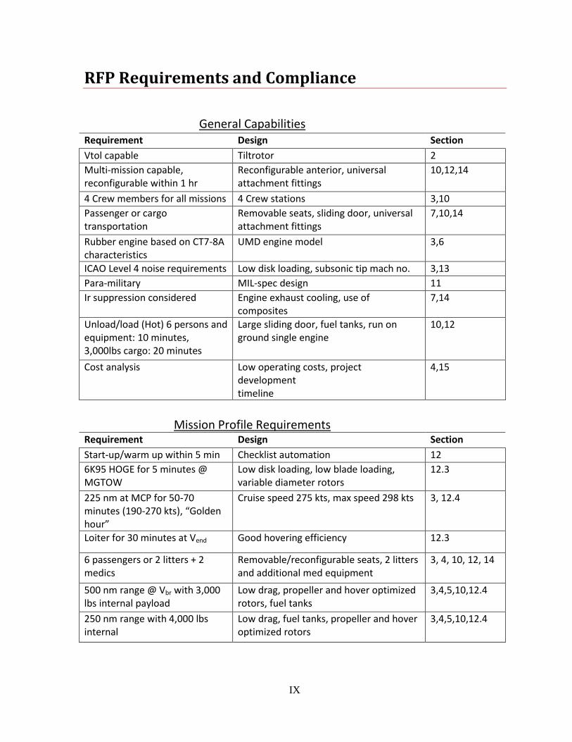
RFP Requirements and Compliance
General Capabilities
Requirement Design Section
Vtol capable Tiltrotor 2
Multi-mission capable, reconfigurable within 1 hr
Reconfigurable anterior, universal attachment fittings
10,12,14
4 Crew members for all missions 4 Crew stations 3,10
Passenger or cargo transportation
Removable seats, sliding door, universal attachment fittings
7,10,14
Rubber engine based on CT7-8A characteristics
UMD engine model 3,6
ICAO Level 4 noise requirements Low disk loading, subsonic tip mach no. 3,13
Para-military MIL-spec design 11
Ir suppression considered Engine exhaust cooling, use of composites
7,14
Unload/load (Hot) 6 persons and equipment: 10 minutes, 3,000lbs cargo: 20 minutes
Large sliding door, fuel tanks, run on ground single engine
10,12
Cost analysis Low operating costs, project development timeline
4,15
Mission Profile Requirements
Requirement Design Section
Start-up/warm up within 5 min Checklist automation 12
6K95 HOGE for 5 minutes @ MGTOW
Low disk loading, low blade loading, variable diameter rotors
12.3
225 nm at MCP for 50-70 minutes (190-270 kts), “Golden hour”
Cruise speed 275 kts, max speed 298 kts 3, 12.4
Loiter for 30 minutes at Vend Good hovering efficiency 12.3
6 passengers or 2 litters + 2 medics
Removable/reconfigurable seats, 2 litters and additional med equipment
3, 4, 10, 12, 14
500 nm range @ Vbr with 3,000 lbs internal payload
Low drag, propeller and hover optimized rotors, fuel tanks
3,4,5,10,12.4
250 nm range with 4,000 lbs internal
Low drag, fuel tanks, propeller and hover optimized rotors
3,4,5,10,12.4
University of Maryland
Design Team 2011
1
Proposal Summary
Concept Design
In response to the 2011 AHS Student Design Competition Request for Proposal
(RFP) for a multi-mission aircraft, co-sponsored by Bell Helicopter Textron, the
University of Maryland graduate student team presents Excalibur, a multi-role
tiltrotor. The graduate team was assembled to take on this challenge of designing
a new multi-mission, VTOL aircraft. The team consisted of five students with
specialties in aeromechanics, computational fluid dynamics, simulation, and one
of the students is also a certificated pilot. Excalibur was designed as a variable
diameter tiltrotor to meet the requirements of the RFP by providing excellent
hover and forward flight performance. All sizing and rotor optimization codes
were developed and extensively validated in-house and were applied within the
project timeframe. Custom software developed at UMD was utilized to provide
all aerodynamic, acoustic, and performance analysis. Computer aided design,
component design, and solid modeling conceptual images were developed using
a variety of solid design tools including CATIA, SolidWorks, and the Modo 501
Design Tool.
The Request for Proposals
The RFP specifies the need for a new vertical lift aircraft with increased
versatility that is capable of multiple missions. Having one rotorcraft that can be
widely deployed and used for many different missions reduces inventory and
maintenance costs by increased commonality of parts. The goal of the multi-
mission design is to optimally blend the competing requirements of three very
different missions, which are motivated by the needs of current events. To
satisfy these requirements the team proposes the design of a tiltrotor. A
description of these three missions along with the proposed capabilities of the
design include:
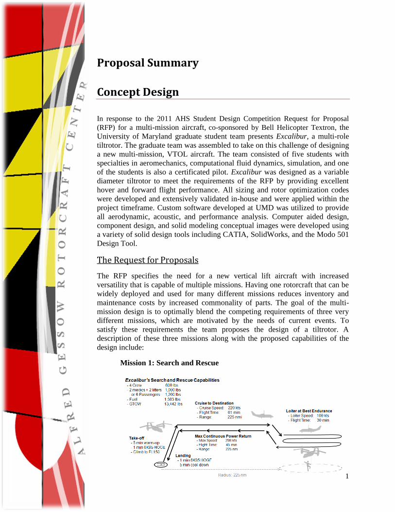
Mission 1: Search and Rescue
T
h
i
s
m
i
s
s
2
ion requires the aircraft to carry a crew of four on the outbound leg, effect
a rescue, and return home carrying two litters and two medical personnel
or an additional six passengers. Critically injured passengers are best
served if they reach the medical facility in the ―golden hour,‖ a window
which is defined in the RFP as 50 to 70 minutes on the return flight. This
mission, therefore, requires the vehicle to be capable of flying between
190 kts and 270 kts to satisfy the ―golden hour‖ requirement. Excalibur is
capable of a 220 kts cruise speed, a 298 kts maximum speed, and a 330
kts dash speed ensuring that rescued persons are returned within this
critical timeframe.
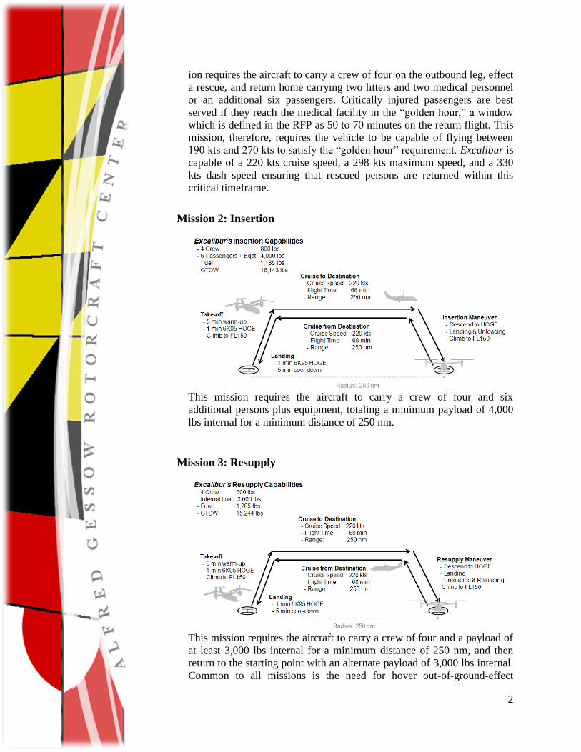
Mission 2: Insertion
This mission requires the aircraft to carry a crew of four and six
additional persons plus equipment, totaling a minimum payload of 4,000
lbs internal for a minimum distance of 250 nm.
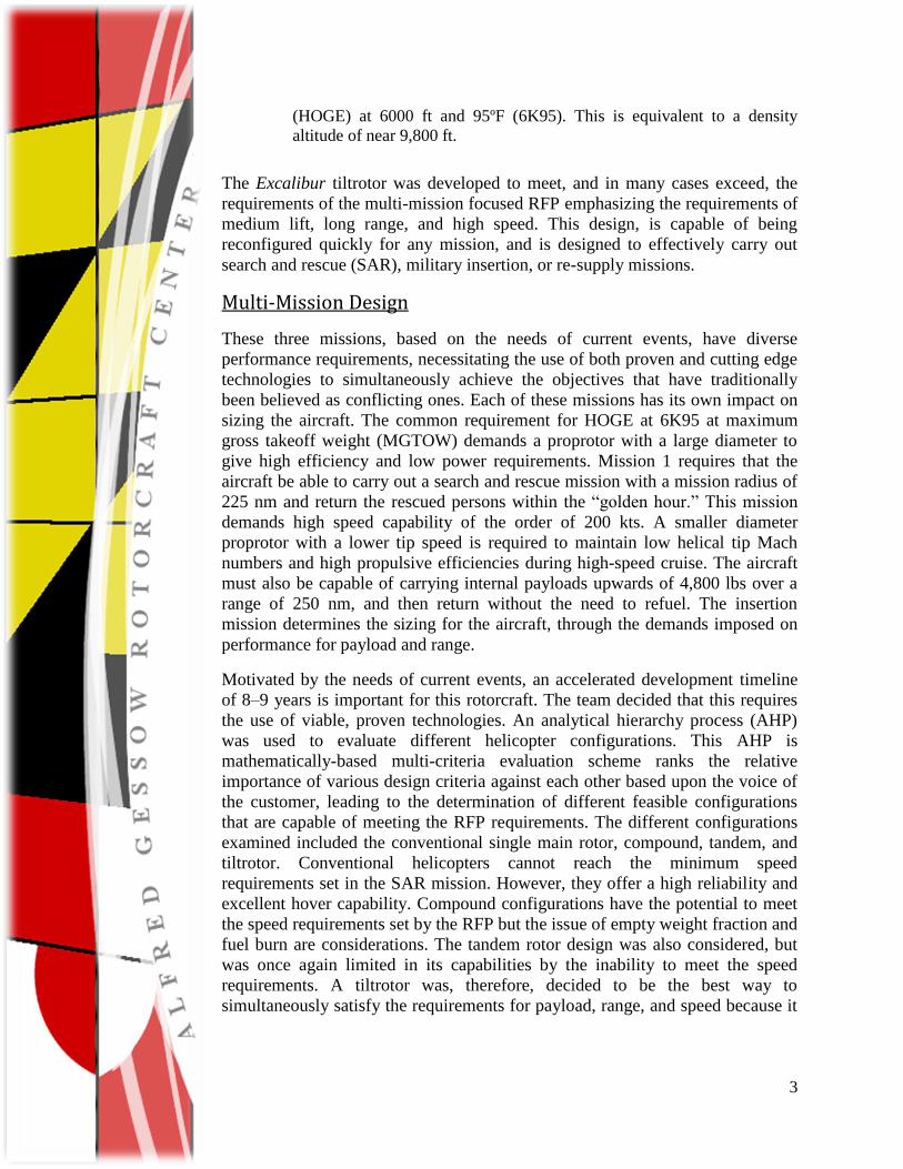
Mission 3: Resupply
This mission requires the aircraft to carry a crew of four and a payload of
at least 3,000 lbs internal for a minimum distance of 250 nm, and then
return to the starting point with an alternate payload of 3,000 lbs internal.
Common to all missions is the need for hover out-of-ground-effect
3
(HOGE) at 6000 ft and 95ºF (6K95). This is equivalent to a density
altitude of near 9,800 ft.
The Excalibur tiltrotor was developed to meet, and in many cases exceed, the
requirements of the multi-mission focused RFP emphasizing the requirements of
medium lift, long range, and high speed. This design, is capable of being
reconfigured quickly for any mission, and is designed to effectively carry out
search and rescue (SAR), military insertion, or re-supply missions.
Multi-Mission Design
These three missions, based on the needs of current events, have diverse
performance requirements, necessitating the use of both proven and cutting edge
technologies to simultaneously achieve the objectives that have traditionally
been believed as conflicting ones. Each of these missions has its own impact on
sizing the aircraft. The common requirement for HOGE at 6K95 at maximum
gross takeoff weight (MGTOW) demands a proprotor with a large diameter to
give high efficiency and low power requirements. Mission 1 requires that the
aircraft be able to carry out a search and rescue mission with a mission radius of
225 nm and return the rescued persons within the ―golden hour.‖ This mission
demands high speed capability of the order of 200 kts. A smaller diameter
proprotor with a lower tip speed is required to maintain low helical tip Mach
numbers and high propulsive efficiencies during high-speed cruise. The aircraft
must also be capable of carrying internal payloads upwards of 4,800 lbs over a
range of 250 nm, and then return without the need to refuel. The insertion
mission determines the sizing for the aircraft, through the demands imposed on
performance for payload and range.
Motivated by the needs of current events, an accelerated development timeline
of 8–9 years is important for this rotorcraft. The team decided that this requires
the use of viable, proven technologies. An analytical hierarchy process (AHP)
was used to evaluate different helicopter configurations. This AHP is
mathematically-based multi-criteria evaluation scheme ranks the relative
importance of various design criteria against each other based upon the voice of
the customer, leading to the determination of different feasible configurations
that are capable of meeting the RFP requirements. The different configurations
examined included the conventional single main rotor, compound, tandem, and
tiltrotor. Conventional helicopters cannot reach the minimum speed
requirements set in the SAR mission. However, they offer a high reliability and
excellent hover capability. Compound configurations have the potential to meet
the speed requirements set by the RFP but the issue of empty weight fraction and
fuel burn are considerations. The tandem rotor design was also considered, but
was once again limited in its capabilities by the inability to meet the speed
requirements. A tiltrotor was, therefore, decided to be the best way to
simultaneously satisfy the requirements for payload, range, and speed because it
4
has the capability to hover and then transition to high speed forward flight, while
still being able to meet the payload and range requirements.
A tiltrotor configuration presents its own set of challenges. Influenced by the
need to hover at 6K95, to have a low downwash that will not hamper rescue, and
have low susceptibility to brownout, it was decided that a disk loading of around
10 lbs/ft2 was required. This decision led to a large diameter rotor that proved
inefficient in airplane mode. Conflicting forward flight requirements are what
makes designing a tiltrotor so challenging. Thus, the team decided upon a
variable diameter tiltrotor (VDTR) concept that has a larger diameter in hover
and a lower diameter in propeller mode. Variable diameter rotors have been
studied, and in many cases considered for other tiltrotor designs because the
concept provides the necessary performance in hover without compromising
forward flight efficiency. The VDTR has also been successfully wind tunnel
tested, demonstrating its feasibility for use on an aircraft within the project
development timeline.
Sizing the tiltrotor was performed using a modified Tischenko methodology,
where helicopter parameters and weights associated with the tail rotor were
removed and wing related terms were added. The modified sizing code uses
statistical data to estimate the various component weights. Certain component
weights were estimated by using the NASA Design and Analysis of Rotorcraft
(NDARC) code. To ensure the confidence in the prediction of the team‘s sizing
code, it was validated using the NDARC. Using the same initial values, the
UMD and NDARC codes converged within 6% in their empty weight
calculation
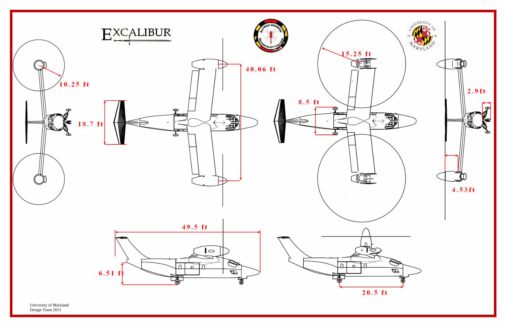
The resulting tiltrotor is shown in Foldout 1 where the overall vehicle
dimensions are illustrated.
Variable Diameter Rotor Design
Excalibur is different from traditional tiltrotors because it is has been developed
from the beginning with emphasis on the variable diameter concept. This makes
the aircraft not just a tiltrotor but a true convertible rotor aircraft. Such an
innovative rotor system offers numerous advantages.
Hover efficiency is greatly improved, with a power loading of 7.5 lb/hp and a
disk loading of only 11 lb/ft2, comparable to conventional helicopters. In
forward flight, decreasing the proprotor diameter resulted in a significant
increase in propulsive efficiency.
An added advantage of the VDTR concept is the ability to take off and land on
runways like fixed-wing aircraft when the rotor is fully retracted. This feature
significantly increases the payload capacity, compared to a tiltrotor without
retracting rotor blades, allowing the vehicle to take off with 50% more payload
compared to helicopter mode. Not only does this increase operational capability,
but also increases survivability as the aircraft can now safely land as an airplane
5
in the event of engine failure in forward flight or in the event that the nacelle
tilting mechanism fails.
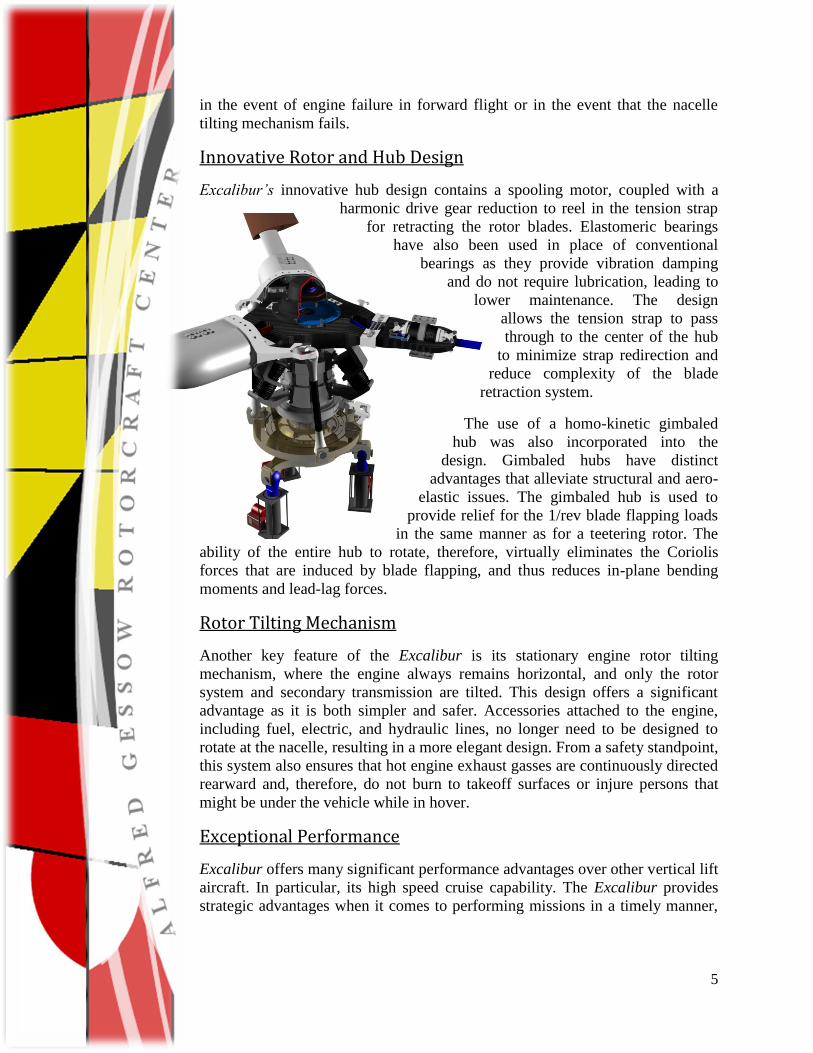
Innovative Rotor and Hub Design
Excalibur’s innovative hub design contains a spooling motor, coupled with a
harmonic drive gear reduction to reel in the tension strap
for retracting the rotor blades. Elastomeric bearings
have also been used in place of conventional
bearings as they provide vibration damping
and do not require lubrication, leading to
lower maintenance. The design
allows the tension strap to pass
through to the center of the hub
to minimize strap redirection and
reduce complexity of the blade
retraction system.
The use of a homo-kinetic gimbaled
hub was also incorporated into the
design. Gimbaled hubs have distinct
advantages that alleviate structural and aero-
elastic issues. The gimbaled hub is used to
provide relief for the 1/rev blade flapping loads
in the same manner as for a teetering rotor. The
ability of the entire hub to rotate, therefore, virtually eliminates the Coriolis
forces that are induced by blade flapping, and thus reduces in-plane bending
moments and lead-lag forces.
Rotor Tilting Mechanism
Another key feature of the Excalibur is its stationary engine rotor tilting
mechanism, where the engine always remains horizontal, and only the rotor
system and secondary transmission are tilted. This design offers a significant
advantage as it is both simpler and safer. Accessories attached to the engine,
including fuel, electric, and hydraulic lines, no longer need to be designed to
rotate at the nacelle, resulting in a more elegant design. From a safety standpoint,
this system also ensures that hot engine exhaust gasses are continuously directed
rearward and, therefore, do not burn to takeoff surfaces or injure persons that
might be under the vehicle while in hover.
Exceptional Performance
Excalibur offers many significant performance advantages over other vertical lift
aircraft. In particular, its high speed cruise capability. The Excalibur provides
strategic advantages when it comes to performing missions in a timely manner,
6
with greater range and endurance while requiring less fuel. This leads to a more
economical aircraft. Key features of the aircraft include:
Increased Speed: The RFP requirement is for a max continuous speed of 190–
270 kts. The ability to cruise at 225 kts over distances of 500 nm, with a dash
speed of 330 kts, ensures that the mission is completed quickly and efficiently.
Longer Range: Excalibur satisfies the RFP requirement of 500nm. Because of
its higher cruise efficiency, it has a combat radius 52% further than the UH-60A
Black Hawk, a helicopter with a similar empty weight.
Fuel Efficient: With its ability to fly further and faster, Excalibur offers a great
increase in its fuel efficiency over all previous helicopter or tiltrotors
Optimized Rotor Design: The ability to change rotor diameter results in a
propulsive efficiency of 85% while maintaining a hover power loading of only
7.4 lb/hp, greater than many utility helicopters.
Survivability: Low rotor disk loading, high tip speeds, and high rotor inertia
provides good autorotational capability. Also, the reduced diameter rotors in
forward flight make conventional airplane landings possible without
compromising operational safety.
HOGE Capability: HOGE at MGTOW is ensured at the RFP-required 6K95
with a good thrust/operating margin for maneuvers. This capability is currently
unmatched by today‘s current tiltrotor aircraft.
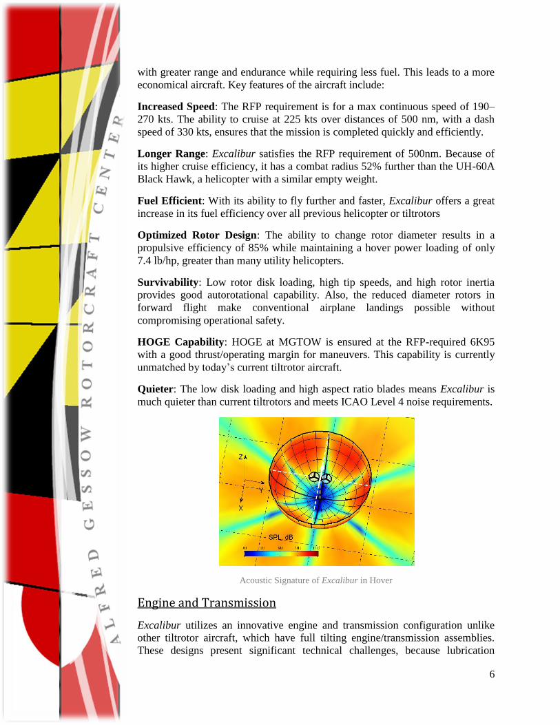
Quieter: The low disk loading and high aspect ratio blades means Excalibur is
much quieter than current tiltrotors and meets ICAO Level 4 noise requirements.
Acoustic Signature of Excalibur in Hover
Engine and Transmission
Excalibur utilizes an innovative engine and transmission configuration unlike
other tiltrotor aircraft, which have full tilting engine/transmission assemblies.
These designs present significant technical challenges, because lubrication
7
systems, generators, cooling systems, and hydraulics must operate over a wide
range of nacelle angles. Excalibur has engines that remain horizontal in all flight
modes and only the rotor hub and second stage transmission need to be tilted.
The engines also operate at a lower SFC than many other engines with similar
power ratings, enabling rotor speed to be decreased by up to 10% through engine
speed variations.
Mechanically simple design eliminates the redesign of generators, cooling
systems, and other engine mounted accessories
Rearward directed exhaust gasses eliminate danger to personnel during search
and rescue.
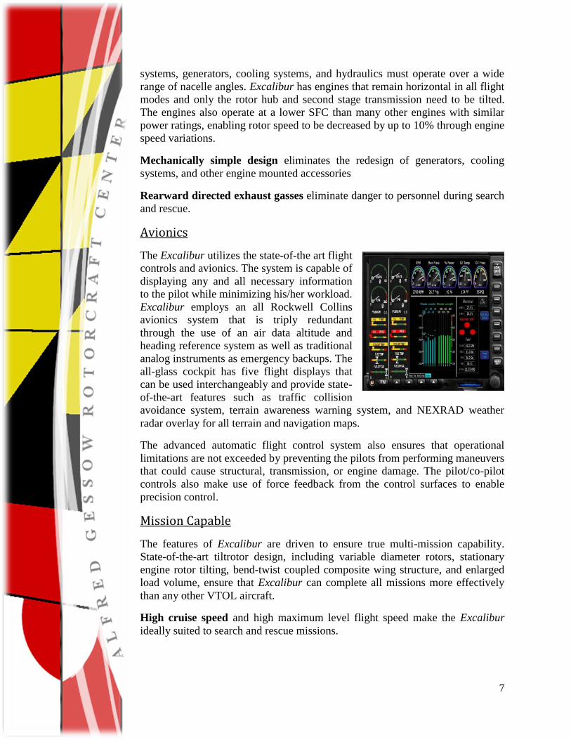
Avionics
The Excalibur utilizes the state-of-the art flight
controls and avionics. The system is capable of
displaying any and all necessary information
to the pilot while minimizing his/her workload.
Excalibur employs an all Rockwell Collins
avionics system that is triply redundant
through the use of an air data altitude and
heading reference system as well as traditional
analog instruments as emergency backups. The
all-glass cockpit has five flight displays that
can be used interchangeably and provide state-
of-the-art features such as traffic collision
avoidance system, terrain awareness warning system, and NEXRAD weather
radar overlay for all terrain and navigation maps.
The advanced automatic flight control system also ensures that operational
limitations are not exceeded by preventing the pilots from performing maneuvers
that could cause structural, transmission, or engine damage. The pilot/co-pilot
controls also make use of force feedback from the control surfaces to enable
precision control.
Mission Capable
The features of Excalibur are driven to ensure true multi-mission capability.
State-of-the-art tiltrotor design, including variable diameter rotors, stationary
engine rotor tilting, bend-twist coupled composite wing structure, and enlarged
load volume, ensure that Excalibur can complete all missions more effectively
than any other VTOL aircraft.
High cruise speed and high maximum level flight speed make the Excalibur
ideally suited to search and rescue missions.
8
Large cabin interior provides room for two stretchers while comfortably
accommodating two medical personnel and medical equipment.
The easily reconfigurable design seats 6 fully-equipped troops with equipment,
and the large door and low floor level allow unhindered ingress and egress.
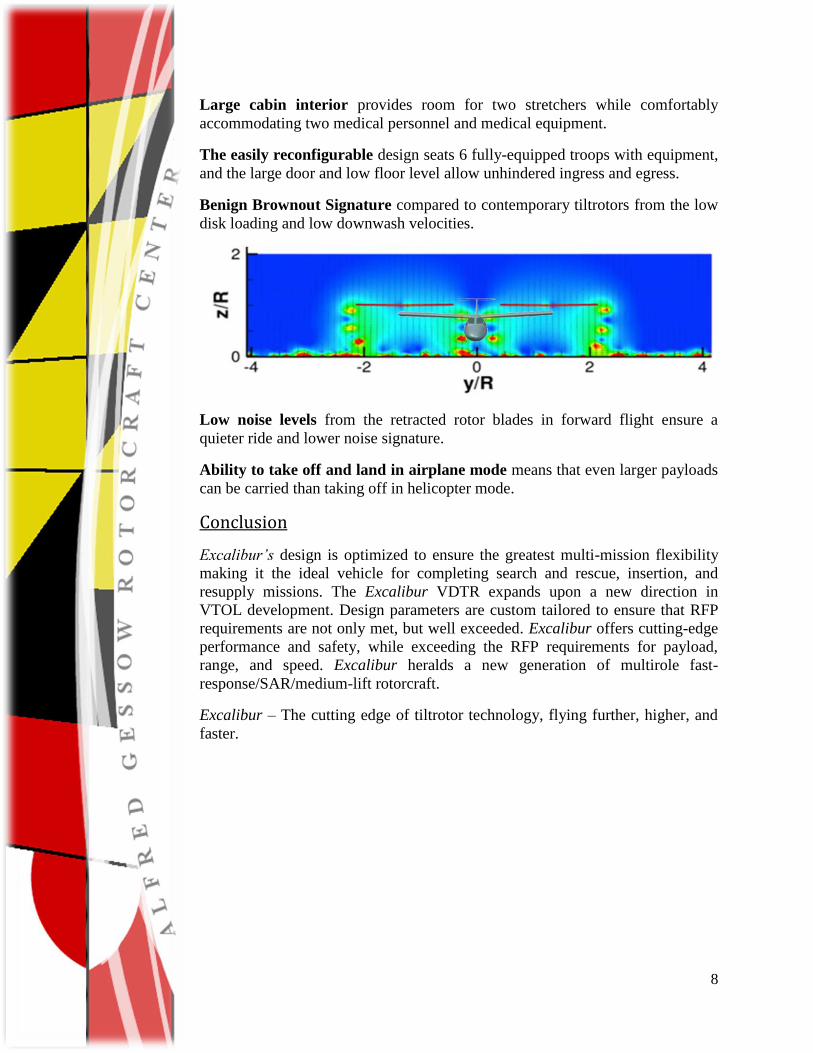
Benign Brownout Signature compared to contemporary tiltrotors from the low
disk loading and low downwash velocities.
Low noise levels from the retracted rotor blades in forward flight ensure a
quieter ride and lower noise signature.
Ability to take off and land in airplane mode means that even larger payloads
can be carried than taking off in helicopter mode.
Conclusion
Excalibur’s design is optimized to ensure the greatest multi-mission flexibility
making it the ideal vehicle for completing search and rescue, insertion, and
resupply missions. The Excalibur VDTR expands upon a new direction in
VTOL development. Design parameters are custom tailored to ensure that RFP
requirements are not only met, but well exceeded. Excalibur offers cutting-edge
performance and safety, while exceeding the RFP requirements for payload,
range, and speed. Excalibur heralds a new generation of multirole fast-
response/SAR/medium-lift rotorcraft.
Excalibur – The cutting edge of tiltrotor technology, flying further, higher, and
faster.
2011 AHS Design Proposal Page 9
1 Introduction
Tiltrotors have historically been associated with levels of performance that are not as good as
helicopters for what helicopters normally do (i.e., hover and fly at low speeds with great
efficiency) and inferior to airplanes for what they do (i.e., fly fast over long ranges with good
payloads). The challenges in the design of a single aircraft that can operate in both flight regimes
has led to concepts that have many compromises in performance and other capabilities, to the
point that they are usually operationally substantially inferior to both helicopters and to airplanes.
Through the process of this design, the team recognizes that a tiltrotor is always a mix of trade-
offs and fully understands these challenges. The proposed Excalibur tiltrotor design with its
variable diameter rotor concept attempts to take such a class of aircraft into the next generation,
creating an aircraft that truly deserves the reputation of one that has the full capabilities of a
helicopter and also most of the capabilities of airplane. The current design takes the next step
towards eliminating many of the compromises that have historically plagued tiltrotor designs.
The demands being placed on VTOL aircraft will require increasingly new and innovative
solutions, as demonstrated by the release of the Army‘s Joint-Multi-Role (JMR) initiative. The
requirements pointing towards the need for quantum advances in the state-of-the-art for vertical
lift technologies. The Excalibur tiltrotor is designed to fulfill these requirements and bring VTOL
flight to the cutting edge of performance.
2 Vehicle Configuration and Selection
In this section, an outline of the considerations that went into the design of the vehicle discussed.
The main design philosophy taken was focused towards the multi-mission capability of the
aircraft. The RFP made it clear that the vehicle to be designed must be able to be configured
easily and quickly for a wide variety of missions. This goal inevitably led to a careful
consideration of several different vehicle configurations. A tiltrotor configuration was
subsequently chosen that would meet all requirements established in the RFP, as well as having
the technology readiness to be developed and deployed in a relatively short period of time.
2.1 Mission Requirements The RFP proposed three missions that the vehicle to be designed must successfully perform. The
different attributes of the three missions are described as follows:
Search and Rescue – Some of the major conditions that affect the ability of the vehicle to
perform this mission include: the ability to carry four crew with two medical litters and two
medical personnel plus equipment, a hover out of ground effect (HOGE) at 6K95, a radius of
action of 225 nm, and a return flight of 225 nm at maximum continuous power within 50–70
minutes. This requirement means that the aircraft must be capable of reaching speeds between
and 190 kts and 270 kts. This range of forward speed is difficult for conventional helicopters
because they can only reach max speeds around 170 kts.
Insertion – The insertion mission is different from the search and rescue mission. This mission
requires that the vehicle be able to carry 4 crew plus 6 passengers and equipment totaling 4,000
2011 AHS Design Proposal Page 10
lbs a total of 250 nm, and then return to base with the 4 crew members. This is the main sizing
mission for the vehicle as it has the highest payload requirements and has a significant radius of
action. The internal payload of 4,000 lbs consequently results in the overall size of the being
increased to accommodate the payload, range, and fuel to satisfy the mission requirements.
Resupply – This mission is a variation of the insertion mission. It requires that the vehicle be
able to carry 3,000 lbs of internal payload to a range of 250 nm, and then return with 3,000 lbs of
alternate internal payload. This mission initially appears to be the most difficult mission to
accomplish because the internal payload is transported a total distance of 500 nm. However, the
total internal payload is actually 1,000 lbs less than that of the insertion mission.
To put these three missions into proper perspective, it is important to determine the key design
drivers for each mission and how they may impact the overall design of the vehicle. The search
and rescue mission, for example, places an emphasis on speed. The vehicle will need to have the
capability to return the injured person/persons within the ―Golden Hour,‖ which is defined as 50
to 70 minutes on the return flight of 225 nm. Both the insertion and resupply mission require a
relatively large payload be carried a long distance. This requires that the vehicle have good cruise
efficiency. None of the missions requires any extended periods of hover, and more than 90% of
all the missions are in cruise flight. All the missions had to meet the very stringent design
constraint of hovering for 10 min at 6K95 OGE. Analysis of the RFP showed that the final design
vehicle should have the following attributes: The vehicle should have a wing with high L/D, low
drag fuselage, large internal storage area, high maximum speed, good hovering efficiency, ability
to quickly load and unload passengers, and be easily reconfigured between missions.
Accomplishing all of these objectives in one vehicle is a significant challenge as some of these
capabilities are conflicting. For example, increasing internal cabin storage volume will increase
the fuselage dimensions and so increase parasite drag. The issues related to these types of design
trades is represented throughout the remainder of this report.
2.2 Examination of Different Configurations As with the design of any aircraft, it is important to determine what vehicle configurations
provide the capability to perform the desired mission profiles. The team, therefore, decided to
examine and compare the capabilities of the conventional helicopter against, compound
helicopters, tandem rotor helicopters, and various types of convertible rotor vehicles, e.g. the
conventional tiltrotor.
2.2.1 Conventional Helicopters The first design examined was the conventional single main rotor helicopter with a tail rotor.
This design is extremely reliable with low production and maintenance costs. The conventional
helicopter design offers many advantages, because they have good endurance, low empty weight
fraction, as well as low risk in their design. Conventional helicopters are the most widely used
configuration, and there are much historical and experimental data to aide in the design of new
aircraft. However, conventional helicopter configurations have some major disadvantages that
often result in trade-offs in their design. For example, they tend to have poor range efficiency and
low cruise and maximum speed capabilities. This outcome is mainly a consequence of the
difficulty in designing a rotor system that is efficient for both hover and cruise. Rotors experience
asymmetric lift as they fly faster and eventually encounter retreating blade stall and drag
divergence of the advancing blade. For the current requirements, a conventional helicopter would
be limited to the lower speeds and the ability to perform the search and rescue mission and return
within the ―Golden Hour‖ would be all but impossible.
2011 AHS Design Proposal Page 11
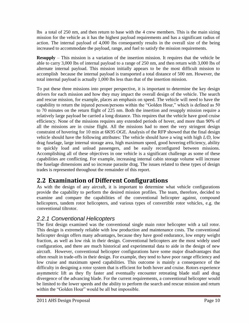
2.2.2 Compound Helicopters Compound helicopters can increase both the range efficiency and speed capabilities over
conventional designs. There are traditionally three ways to compound a helicopter: by the
addition of a lift-augmenting wing, by the addition of a propulsive thruster, or by combined lift
and thrust augmentation. Technology demonstrators such as the Sikorsky X2 and the Eurocopter
X3 are shown in Figure 2.1 to illustrate two different methods of compounding.
Figure 2.1: a) Sikorsky X-2 and b) Eurocopter X3 compound helicopter technology demonstrators
Lift and/or thrust compounding allows the helicopter to fly faster and further but at the cost of a
higher empty weight fraction and increased power requirements. A lift compounded helicopter
utilizes a small wing to offload the lift the main rotor. This lift augmentation alleviates some of
the effects of retreating blade stall. However, drag divergence of the advancing blades still
becomes a hurdle to flying faster. Therefore, thrust compounding is often incorporated but at the
expensive of increased power and fuel requirements. This design leads to lower endurance
efficiencies and lower payload capabilities. A compound design would allow the vehicle to
achieve the necessary speed and range requirements, but would add a significant amount of
complexity to the overall design. This added complexity would reduce reliability while
increasing manufacturing costs. In addition, a compound design would add a significant amount
of empty weight, increasing the empty weight faction. However the added lift generated in
forward flight from compounding would most likely counter the losses and payload might not be
greatly affected.
The confidence level in the design of these vehicles is relatively low and there are no compound
helicopters currently in production for either the military or civilian markets. However, there is
no shortage of historical or experimental data for these aircraft. Also, with the success of the
Sikorsky X2 and the Eurocopter X3 (shown in Figure 2.1), there has been renewed interest in
such designs and a closer look at their capabilities is required1,2.
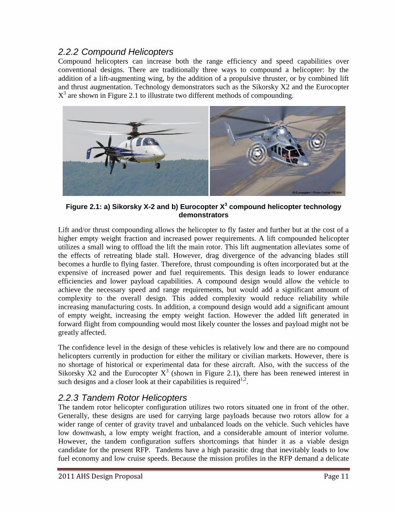
2.2.3 Tandem Rotor Helicopters The tandem rotor helicopter configuration utilizes two rotors situated one in front of the other.
Generally, these designs are used for carrying large payloads because two rotors allow for a
wider range of center of gravity travel and unbalanced loads on the vehicle. Such vehicles have
low downwash, a low empty weight fraction, and a considerable amount of interior volume.
However, the tandem configuration suffers shortcomings that hinder it as a viable design
candidate for the present RFP. Tandems have a high parasitic drag that inevitably leads to low
fuel economy and low cruise speeds. Because the mission profiles in the RFP demand a delicate
2011 AHS Design Proposal Page 12
balance between range, speed, and payload capacity, the tandem cannot deliver the desired
spectrum of performance. In particular, they cannot achieve the speeds close to the minimum
required speed the RFP dictates for the Search and Rescue mission of 190 kts. Tandem rotor
helicopters are also traditionally larger than what is required for the RFP, e.g. both the CH-46 and
CH-47 (Figure 2.2) can carry more than 25 passengers. The cost of production is also
considerably higher than the equivalent single main rotor tail rotor design. The cost of such a
platform, however, is lower than that of the compound helicopter and of the tiltrotor. Ultimately
the tandem does not offer an innovative or effective solution to the requirements of this RFP.
Figure 2.2: CH-47 tandem rotor helicopter
2.2.4 Convertible Rotor Aircraft The main advantage of using a tiltrotor or tiltwing design, often termed convertible rotor aircraft,
is the ability to takeoff vertically (like a helicopter) and transition to forward flight (and fly like
an airplane). This capability allows the tiltrotor to achieve much higher forward flight speeds
than for a conventional helicopter. The main drawbacks of a tiltrotor design are a higher empty
weight fraction, cost of production, and complexity of the design. The increased empty weight
fraction, coupled with the negative download produced from the wing in the rotor wake, yields a
reduction of total payload or degradation in rotor hovering performance. There has been a great
deal of research into tiltwing aircraft that can tilt the wing along with the rotors to eliminate the
issues of download. However, these designs tend to be complex and carry a significant amount of
weight in the tilting actuation systems. There have been nearly a dozen successful research
programs on convertible rotor systems, mainly the XV-15, which led to the development of both
the V-22 Osprey and the BA-609 civilian tiltrotor3. Many scientists and engineers agree that
tiltrotors fill a unique niche as they are neither helicopter nor airplane but have certain advantages
of both. Dr. Leishman4 agrees that ―…clearly any aircraft that removes or otherwise limits a
dependency on concrete runways gives any operator, military or civil, an unparalleled operational
capability and flexibility.‖
2011 AHS Design Proposal Page 13
2.3 Analytical Hierarchy Process and House of Quality When presented with a decision on a specific configuration, it is important to make a choice
based on an explicit evaluation of the criteria for the desired configuration. Establishing the
evaluation criteria is, therefore, the first step, which came about through the analysis of the RFP
requirements. Each of these requirements must be evaluated then on their relative importance
against each other, the fundamental question is: What concepts meet the objectives of the top-
level requirements? This question is answered by determining the feasible concepts through the
analysis of different vehicle configurations.
To evaluate the different concepts and determine how they meet the objectives set forth by the
RFP, an Analytical Hierarchy Process (AHP) was used. This is a mathematical technique for
multi-criteria decision making and is based on pair-wise comparisons between competing
alternatives. This process allows for the consideration of both objective and subjective opinions
about various designs and the results from the AHP provide relative weights that can be used in a
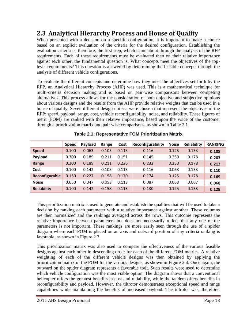
house of quality. Seven different design criteria were chosen that represent the objectives of the
RFP: speed, payload, range, cost, vehicle reconfigurability, noise, and reliability. These figures of
merit (FOM) are ranked with their relative importance, based upon the voice of the customer
through a prioritization matrix and pair wise comparisons, as shown in Table 2.1.
Table 2.1: Representative FOM Prioritization Matrix
Speed Payload Range Cost Reconfigurability Noise Reliability RANKING
Speed 0.100 0.063 0.105 0.113 0.116 0.125 0.133 0.108 Payload 0.300 0.189 0.211 0.151 0.145 0.250 0.178 0.203 Range 0.200 0.189 0.211 0.226 0.232 0.250 0.178 0.212 Cost 0.100 0.142 0.105 0.113 0.116 0.063 0.133 0.110 Reconfigurable 0.150 0.227 0.158 0.170 0.174 0.125 0.178 0.169 Noise 0.050 0.047 0.053 0.113 0.087 0.063 0.067 0.068 Reliability 0.100 0.142 0.158 0.113 0.130 0.125 0.133 0.129
This prioritization matrix is used to generate and establish the qualities that will be used to take a
decision by ranking each parameter with a relative importance against another. These columns
are then normalized and the rankings averaged across the rows. This outcome represents the
relative importance between parameters but does not necessarily reflect that any one of the
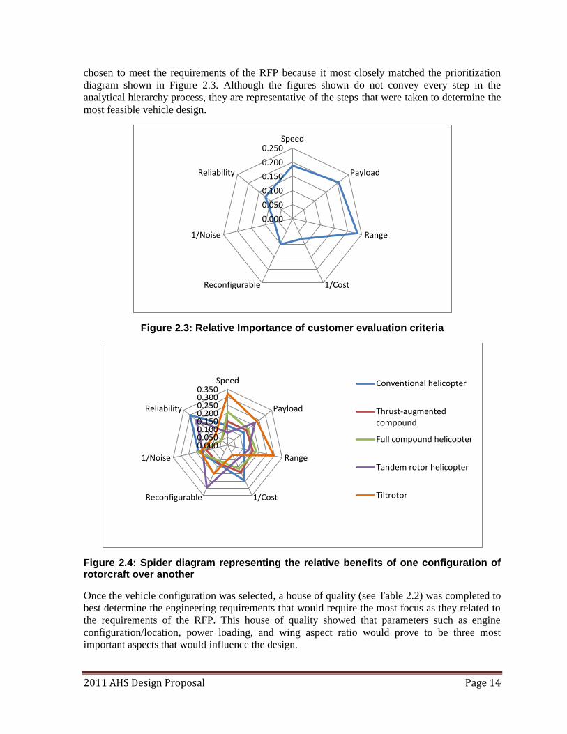
parameters is not important. These rankings are more easily seen through the use of a spider
diagram where each FOM is placed on an axis and outward position of any criteria ranking is
favorable, as shown in Figure 2.3.
This prioritization matrix was also used to compare the effectiveness of the various feasible
designs against each other in descending order for each of the different FOM metrics. A relative
weighting of each of the different vehicle designs was then obtained by applying the
prioritization matrix of the FOM for the various designs, as shown in Figure 2.4. Once again, the
outward on the spider diagram represents a favorable trait. Such results were used to determine
which vehicle configuration was the most viable option. The diagram shows that a conventional
helicopter offers the greatest benefits in cost and reliability, while the tandem offers benefits in
reconfigurability and payload. However, the tiltrotor demonstrates exceptional speed and range
capabilities while maintaining the benefits of increased payload. The tiltrotor was, therefore,
2011 AHS Design Proposal Page 14
chosen to meet the requirements of the RFP because it most closely matched the prioritization
diagram shown in Figure 2.3. Although the figures shown do not convey every step in the
analytical hierarchy process, they are representative of the steps that were taken to determine the
most feasible vehicle design.
Figure 2.3: Relative Importance of customer evaluation criteria
Figure 2.4: Spider diagram representing the relative benefits of one configuration of rotorcraft over another
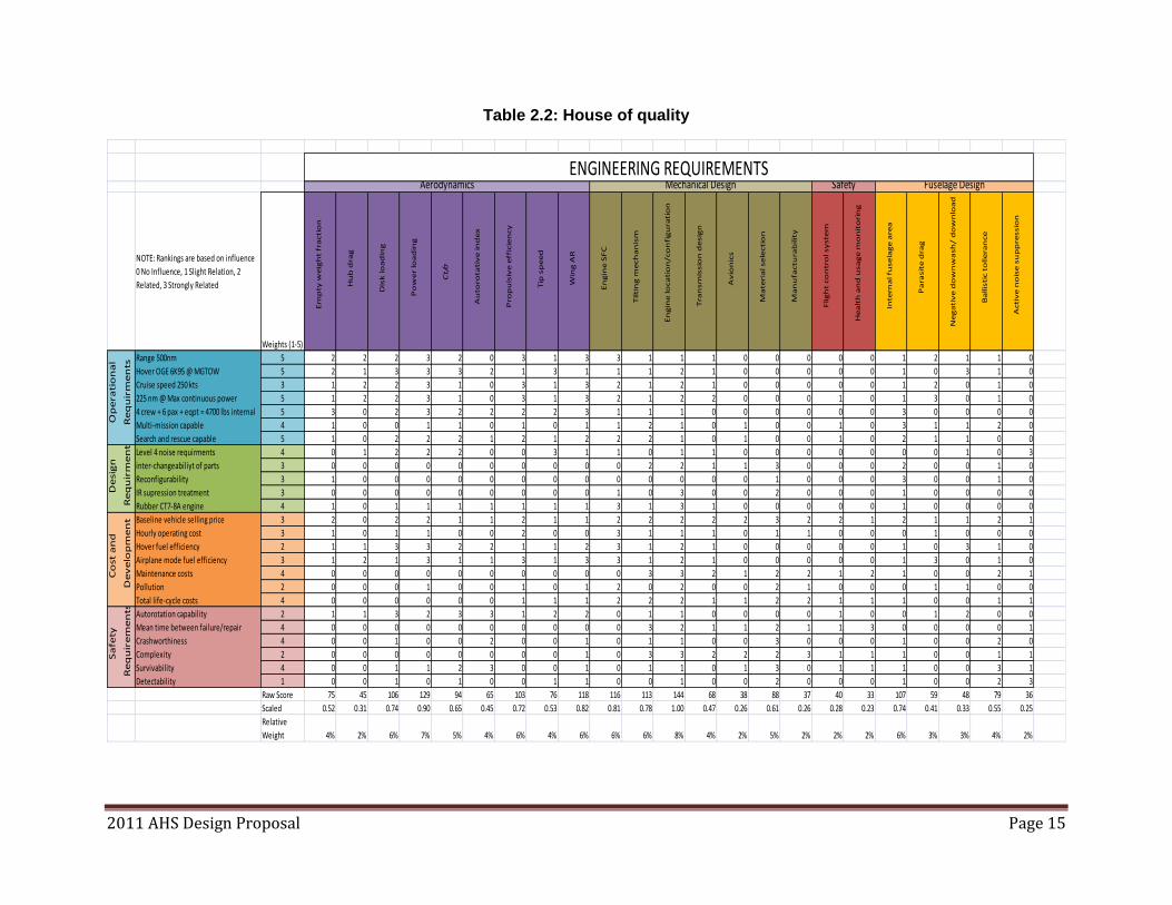
Once the vehicle configuration was selected, a house of quality (see Table 2.2) was completed to
best determine the engineering requirements that would require the most focus as they related to
the requirements of the RFP. This house of quality showed that parameters such as engine
configuration/location, power loading, and wing aspect ratio would prove to be three most
important aspects that would influence the design.
0.000
0.050
0.100
0.150
0.200
0.250Speed
Payload
Range
1/CostReconfigurable
1/Noise
Reliability
0.0000.0500.1000.1500.2000.2500.3000.350
Speed
Payload
Range
1/CostReconfigurable
1/Noise
Reliability
Conventional helicopter
Thrust-augmented compound
Full compound helicopter
Tandem rotor helicopter
Tiltrotor
2011 AHS Design Proposal Page 15
Table 2.2: House of quality
NOTE: Rankings are based on influence
0 No Influence, 1 Slight Relation, 2
Related, 3 Strongly Related
Weights (1-5)
Em
pty
we
igh
t fr
acti
on
Hu
b d
rag
Dis
k lo
ad
ing
Po
we
r lo
ad
ing
Ct/σ
Au
toro
tati
ve
in
de
x
Pro
pu
lsiv
e e
ffic
ien
cy
Tip
sp
ee
d
Win
g A
R
En
gin
e S
FC
Tilti
ng
me
ch
an
ism
En
gin
e lo
ca
tio
n/co
nfi
gu
rati
on
Tra
nsm
issio
n d
esig
n
Av
ion
ics
Ma
teri
al se
lecti
on
Ma
nu
factu
rab
ilit
y
Flig
ht
co
ntr
ol sy
ste
m
He
alt
h a
nd
usa
ge
mo
nit
ori
ng
Inte
rna
l fu
se
lag
e a
rea
Pa
rasit
e d
rag
Ne
ga
tiv
e d
ow
nw
ash
/ d
ow
nlo
ad
Ba
llis
tic t
olle
ran
ce
Acti
ve
no
ise
su
pp
ressio
n
Range 500nm 5 2 2 2 3 2 0 3 1 3 3 1 1 1 0 0 0 0 0 1 2 1 1 0
Hover OGE 6K95 @ MGTOW 5 2 1 3 3 3 2 1 3 1 1 1 2 1 0 0 0 0 0 1 0 3 1 0
Cruise speed 250 kts 3 1 2 2 3 1 0 3 1 3 2 1 2 1 0 0 0 0 0 1 2 0 1 0
225 nm @ Max continuous power 5 1 2 2 3 1 0 3 1 3 2 1 2 2 0 0 0 1 0 1 3 0 1 0
4 crew + 6 pax + eqpt = 4700 lbs internal 5 3 0 2 3 2 2 2 2 3 1 1 1 0 0 0 0 0 0 3 0 0 0 0
Multi-mission capable 4 1 0 0 1 1 0 1 0 1 1 2 1 0 1 0 0 1 0 3 1 1 2 0
Search and rescue capable 5 1 0 2 2 2 1 2 1 2 2 2 1 0 1 0 0 1 0 2 1 1 0 0
Level 4 noise requirments 4 0 1 2 2 2 0 0 3 1 1 0 1 1 0 0 0 0 0 0 0 1 0 3
inter-changeabiliyt of parts 3 0 0 0 0 0 0 0 0 0 0 2 2 1 1 3 0 0 0 2 0 0 1 0
Reconfigurability 3 1 0 0 0 0 0 0 0 0 0 0 0 0 0 1 0 0 0 3 0 0 1 0
IR supression treatment 3 0 0 0 0 0 0 0 0 0 1 0 3 0 0 2 0 0 0 1 0 0 0 0
Rubber CT7-8A engine 4 1 0 1 1 1 1 1 1 1 3 1 3 1 0 0 0 0 0 1 0 0 0 0
Baseline vehicle selling price 3 2 0 2 2 1 1 2 1 1 2 2 2 2 2 3 2 2 1 2 1 1 2 1
Hourly operating cost 3 1 0 1 1 0 0 2 0 0 3 1 1 1 0 1 1 0 0 0 1 0 0 0
Hover fuel efficiency 2 1 1 3 3 2 2 1 1 2 3 1 2 1 0 0 0 0 0 1 0 3 1 0
Airplane mode fuel efficiency 3 1 2 1 3 1 1 3 1 3 3 1 2 1 0 0 0 0 0 1 3 0 1 0
Maintenance costs 4 0 0 0 0 0 0 0 0 0 0 3 3 2 1 2 2 1 2 1 0 0 2 1
Pollution 2 0 0 0 1 0 0 1 0 1 2 0 2 0 0 2 1 0 0 0 1 1 0 0
Total life-cycle costs 4 0 0 0 0 0 0 1 1 1 2 2 2 1 1 2 2 1 1 1 0 0 1 1
Autorotation capability 2 1 1 3 2 3 3 1 2 2 0 1 1 0 0 0 0 1 0 0 1 2 0 0
Mean time between failure/repair 4 0 0 0 0 0 0 0 0 0 0 3 2 1 1 2 1 1 3 0 0 0 0 1
Crashworthiness 4 0 0 1 0 0 2 0 0 1 0 1 1 0 0 3 0 0 0 1 0 0 2 0
Complexity 2 0 0 0 0 0 0 0 0 1 0 3 3 2 2 2 3 1 1 1 0 0 1 1
Survivability 4 0 0 1 1 2 3 0 0 1 0 1 1 0 1 3 0 1 1 1 0 0 3 1
Detectability 1 0 0 1 0 1 0 0 1 1 0 0 1 0 0 2 0 0 0 1 0 0 2 3
Raw Score 75 45 106 129 94 65 103 76 118 116 113 144 68 38 88 37 40 33 107 59 48 79 36
Scaled 0.52 0.31 0.74 0.90 0.65 0.45 0.72 0.53 0.82 0.81 0.78 1.00 0.47 0.26 0.61 0.26 0.28 0.23 0.74 0.41 0.33 0.55 0.25
Relative
Weight 4% 2% 6% 7% 5% 4% 6% 4% 6% 6% 6% 8% 4% 2% 5% 2% 2% 2% 6% 3% 3% 4% 2%
De
sig
n
Re
qu
irm
en
ts
Co
st a
nd
De
ve
lop
me
nt
Sa
fety
Re
qu
ire
me
nts
Aerodynamics Mechanical Design Safety Fuselage DesignENGINEERING REQUIREMENTS
Op
era
tio
na
l
Re
qu
irm
en
ts
2011 AHS Design Proposal Page 16
3 Preliminary Tiltrotor Sizing
The RFP defined three very specific missions, each playing a part in the sizing of Excalibur. The
first mission (search and rescue) requires the vehicle to rescue injured persons and return 225 nm
within 50–70 minutes, defined as the ―golden hour.‖ The second and third missions, insertion and
resupply, require a payload of 4,000 lbs and 3,000 lbs, respectively, to be carried. Considering
the requirements of all three missions, Excalibur is designed to be capable of high forward flight
speeds, good hover efficiency at hot and high conditions (6K95), unprecedented cruise
efficiency, and with a good acoustic signature. Because a tiltrotor is a hybrid of a fixed-wing
aircraft and a helicopter, a new method was developed for sizing the aircraft. This method
included changes to the estimation of the mission weights and weight fractions, which
incorporates the empty takeoff weight, payload, the power requirements and the fuel weight. This
new sizing method was conducted for each of the three missions specified in the RFP. The
rigorous process of initial sizing seeks to determine the most difficult mission in terms of the
gross takeoff weight. The limiting mission provided the best estimates of the initial size of the
aircraft and was defined as the most difficult of the three RFP defined missions.
3.1 Description of the Algorithm A preliminary design code, based on Tishchenko‘s methodology1, was developed for the initial
sizing of tiltrotors. The Tishchenko method constitutes basic methodologies and algorithms that
have validated accuracy for determining the size and weight of a rotorcraft. To make
Tishchenko‘s method applicable for tiltrotor designs, it was necessary to institute several
changes. The initial modification to the method involved the removal of the tail rotor related
terms, which included the tail rotor power, tail rotor shaft and tail gear box weight, etc. It was
also necessary to account for the change in power required for a proprotor in forward flight as
compared to a conventional rotor. The weight formulae in Tishchenko‘s method were modified
using the equations from the NASA Design and Analysis of Rotorcraft2 (NDARC) code to
account for the wing and spinner weights. The NDARC code was also used to account for the
addition of wing-related terms, which included the wing contributions to lift and drag and the
addition of a download force during hovering flight. Modifications were also made to add the
spinner weight, which is used to minimize hub drag during forward flight. Because the RFP
specifies a rubber engine (based on the CT7-8A), the engine characteristics were defined based
on the NDARC engine model. Further refinements were made to account for the weight of
additional tiltrotor design features such as the interconnecting drive shaft and rotor system (see
Section 6).
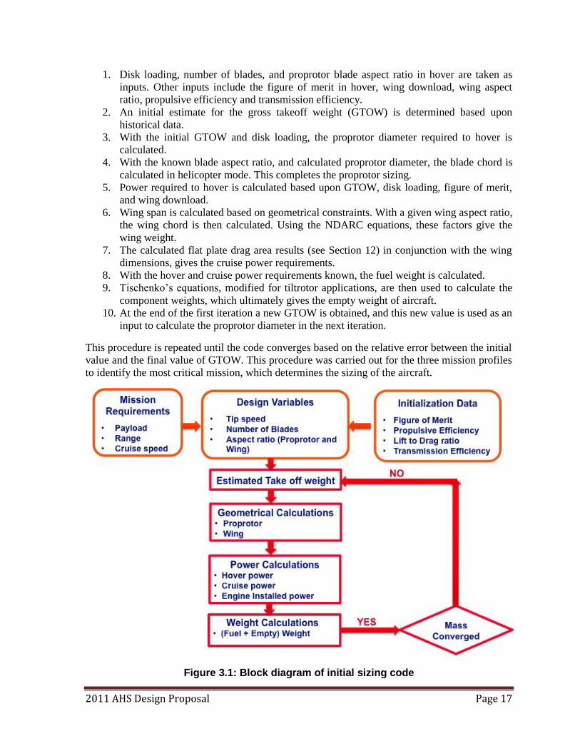
The algorithm used is presented schematically in Figure 3.1. The design code performs an
iterative process that begins with the specification of the required payload, range, and cruise
speed. The user inputs a number of initial parameters that are not given explicitly in the mission
requirements, such as the estimated proprotor figure of merit, propulsive efficiency, transmission
efficiency, proprotor disk loading, blade and wing aspect ratios, tip speed, and number of blades.
These parameters are refined to have precise values though optimization of the requirements for
efficient forward flight and hover, explained in greater detail in Section 12.
The following steps were used in the iterative procedure of the sizing methodology:
2011 AHS Design Proposal Page 17
1. Disk loading, number of blades, and proprotor blade aspect ratio in hover are taken as
inputs. Other inputs include the figure of merit in hover, wing download, wing aspect
ratio, propulsive efficiency and transmission efficiency.
2. An initial estimate for the gross takeoff weight (GTOW) is determined based upon
historical data.
3. With the initial GTOW and disk loading, the proprotor diameter required to hover is
calculated.
4. With the known blade aspect ratio, and calculated proprotor diameter, the blade chord is
calculated in helicopter mode. This completes the proprotor sizing.
5. Power required to hover is calculated based upon GTOW, disk loading, figure of merit,
and wing download.
6. Wing span is calculated based on geometrical constraints. With a given wing aspect ratio,
the wing chord is then calculated. Using the NDARC equations, these factors give the
wing weight.
7. The calculated flat plate drag area results (see Section 12) in conjunction with the wing
dimensions, gives the cruise power requirements.
8. With the hover and cruise power requirements known, the fuel weight is calculated.
9. Tischenko‘s equations, modified for tiltrotor applications, are then used to calculate the
component weights, which ultimately gives the empty weight of aircraft.
10. At the end of the first iteration a new GTOW is obtained, and this new value is used as an
input to calculate the proprotor diameter in the next iteration.
This procedure is repeated until the code converges based on the relative error between the initial
value and the final value of GTOW. This procedure was carried out for the three mission profiles
to identify the most critical mission, which determines the sizing of the aircraft.
Figure 3.1: Block diagram of initial sizing code
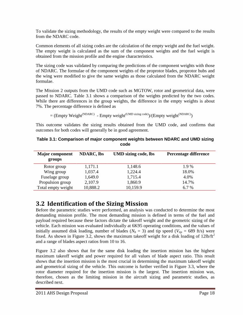
2011 AHS Design Proposal Page 18
To validate the sizing methodology, the results of the empty weight were compared to the results
from the NDARC code.
Common elements of all sizing codes are the calculation of the empty weight and the fuel weight.
The empty weight is calculated as the sum of the component weights and the fuel weight is
obtained from the mission profile and the engine characteristics.
The sizing code was validated by comparing the predictions of the component weights with those
of NDARC. The formulae of the component weights of the proprotor blades, proprotor hubs and
the wing were modified to give the same weights as those calculated from the NDARC weight
formulae.
The Mission 2 outputs from the UMD code such as MGTOW, rotor and geometrical data, were
passed to NDARC. Table 3.1 shows a comparison of the weights predicted by the two codes.
While there are differences in the group weights, the difference in the empty weights is about
7%. The percentage difference is defined as
= (Empty Weight(NDARC) - Empty weight(UMD sizing code))/(Empty weight(NDARC))
This outcome validates the sizing results obtained from the UMD code, and confirms that
outcomes for both codes will generally be in good agreement.
Table 3.1: Comparison of major component weights between NDARC and UMD sizing code
Major component
groups
NDARC, lbs UMD sizing code, lbs Percentage difference
Rotor group 1,171.1 1,148.6 1.9 %
Wing group 1,037.4 1,224.4 18.0%
Fuselage group 1,649.0 1,715.4 4.0%
Propulsion group 2,107.9 1,860.9 14.7%
Total empty weight 10,888.2 10,159.9 6.7 %
3.2 Identification of the Sizing Mission Before the parametric studies were performed, an analysis was conducted to determine the most
demanding mission profile. The most demanding mission is defined in terms of the fuel and
payload required because these factors dictate the takeoff weight and the geometric sizing of the
vehicle. Each mission was evaluated individually at 6K95 operating conditions, and the values of
initially assumed disk loading, number of blades (Nb = 3) and tip speed (Vtip = 689 ft/s) were
fixed. As shown in Figure 3.2, shows the maximum takeoff weight for a disk loading of 12lb/ft2
and a range of blades aspect ratios from 10 to 16.
Figure 3.2 also shows that for the same disk loading the insertion mission has the highest
maximum takeoff weight and power required for all values of blade aspect ratio. This result
shows that the insertion mission is the most crucial in determining the maximum takeoff weight
and geometrical sizing of the vehicle. This outcome is further verified in Figure 3.3, where the
rotor diameter required for the insertion mission is the largest. The insertion mission was,
therefore, chosen as the limiting mission in the aircraft sizing and parametric studies, as
described next.
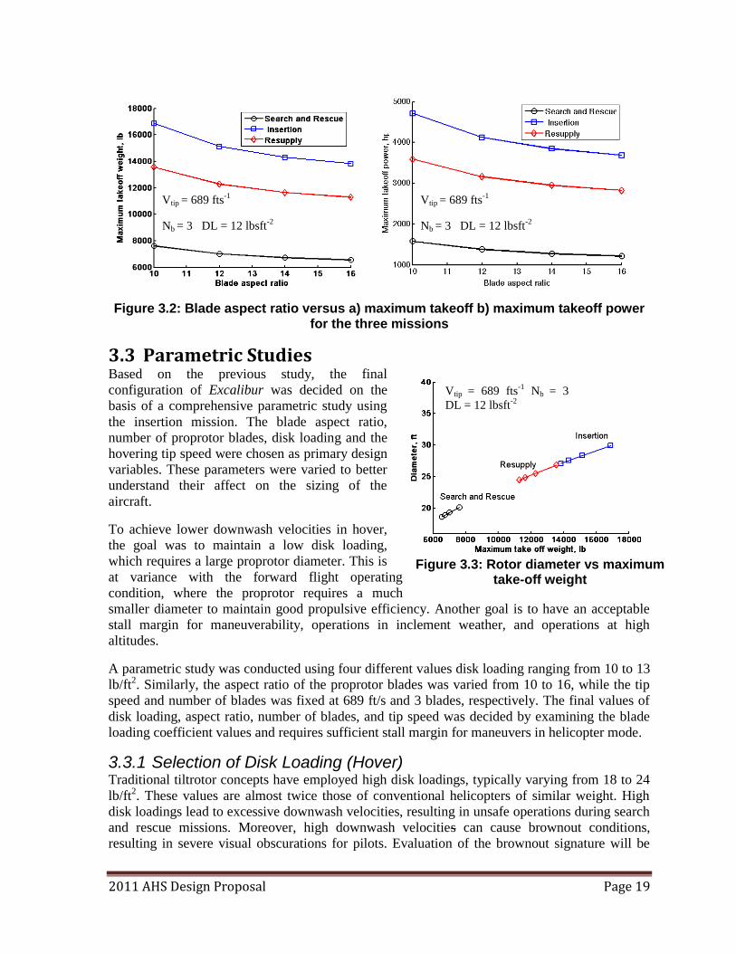
2011 AHS Design Proposal Page 19
Figure 3.2: Blade aspect ratio versus a) maximum takeoff b) maximum takeoff power for the three missions
3.3 Parametric Studies Based on the previous study, the final
configuration of Excalibur was decided on the
basis of a comprehensive parametric study using
the insertion mission. The blade aspect ratio,
number of proprotor blades, disk loading and the
hovering tip speed were chosen as primary design
variables. These parameters were varied to better
understand their affect on the sizing of the
aircraft.
To achieve lower downwash velocities in hover,
the goal was to maintain a low disk loading,
which requires a large proprotor diameter. This is
at variance with the forward flight operating
condition, where the proprotor requires a much
smaller diameter to maintain good propulsive efficiency. Another goal is to have an acceptable
stall margin for maneuverability, operations in inclement weather, and operations at high
altitudes.
A parametric study was conducted using four different values disk loading ranging from 10 to 13
lb/ft2. Similarly, the aspect ratio of the proprotor blades was varied from 10 to 16, while the tip
speed and number of blades was fixed at 689 ft/s and 3 blades, respectively. The final values of
disk loading, aspect ratio, number of blades, and tip speed was decided by examining the blade
loading coefficient values and requires sufficient stall margin for maneuvers in helicopter mode.
3.3.1 Selection of Disk Loading (Hover) Traditional tiltrotor concepts have employed high disk loadings, typically varying from 18 to 24
lb/ft2. These values are almost twice those of conventional helicopters of similar weight. High
disk loadings lead to excessive downwash velocities, resulting in unsafe operations during search
and rescue missions. Moreover, high downwash velocities can cause brownout conditions,
resulting in severe visual obscurations for pilots. Evaluation of the brownout signature will be
Vtip = 689 fts-1
Nb = 3
DL = 12 lbsft-2
Figure 3.3: Rotor diameter vs maximum take-off weight
Vtip = 689 fts-1
Nb = 3 DL = 12 lbsft-2
Vtip = 689 fts-1
Nb = 3 DL = 12 lbsft-2
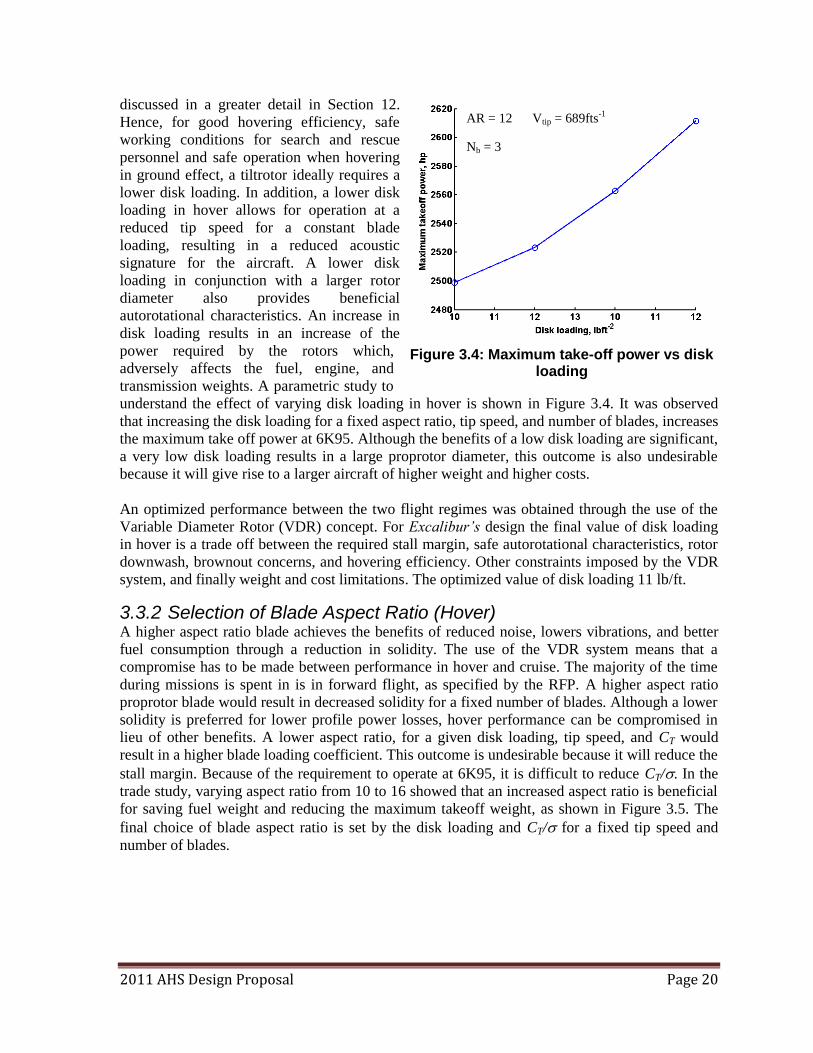
2011 AHS Design Proposal Page 20
discussed in a greater detail in Section 12.
Hence, for good hovering efficiency, safe
working conditions for search and rescue
personnel and safe operation when hovering
in ground effect, a tiltrotor ideally requires a
lower disk loading. In addition, a lower disk
loading in hover allows for operation at a
reduced tip speed for a constant blade
loading, resulting in a reduced acoustic
signature for the aircraft. A lower disk
loading in conjunction with a larger rotor
diameter also provides beneficial
autorotational characteristics. An increase in
disk loading results in an increase of the
power required by the rotors which,
adversely affects the fuel, engine, and
transmission weights. A parametric study to
understand the effect of varying disk loading in hover is shown in Figure 3.4. It was observed
that increasing the disk loading for a fixed aspect ratio, tip speed, and number of blades, increases
the maximum take off power at 6K95. Although the benefits of a low disk loading are significant,
a very low disk loading results in a large proprotor diameter, this outcome is also undesirable
because it will give rise to a larger aircraft of higher weight and higher costs.
An optimized performance between the two flight regimes was obtained through the use of the
Variable Diameter Rotor (VDR) concept. For Excalibur’s design the final value of disk loading
in hover is a trade off between the required stall margin, safe autorotational characteristics, rotor
downwash, brownout concerns, and hovering efficiency. Other constraints imposed by the VDR
system, and finally weight and cost limitations. The optimized value of disk loading 11 lb/ft.
3.3.2 Selection of Blade Aspect Ratio (Hover) A higher aspect ratio blade achieves the benefits of reduced noise, lowers vibrations, and better
fuel consumption through a reduction in solidity. The use of the VDR system means that a
compromise has to be made between performance in hover and cruise. The majority of the time
during missions is spent in is in forward flight, as specified by the RFP. A higher aspect ratio
proprotor blade would result in decreased solidity for a fixed number of blades. Although a lower
solidity is preferred for lower profile power losses, hover performance can be compromised in
lieu of other benefits. A lower aspect ratio, for a given disk loading, tip speed, and CT would
result in a higher blade loading coefficient. This outcome is undesirable because it will reduce the
stall margin. Because of the requirement to operate at 6K95, it is difficult to reduce CT/. In the
trade study, varying aspect ratio from 10 to 16 showed that an increased aspect ratio is beneficial
for saving fuel weight and reducing the maximum takeoff weight, as shown in Figure 3.5. The
final choice of blade aspect ratio is set by the disk loading and CT/ for a fixed tip speed and
number of blades.
AR = 12 Vtip = 689fts-1
Nb = 3
Figure 3.4: Maximum take-off power vs disk loading
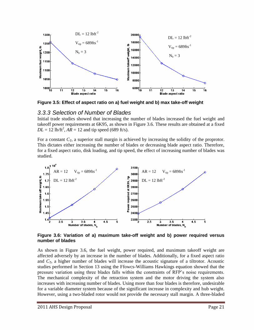
2011 AHS Design Proposal Page 21
Figure 3.5: Effect of aspect ratio on a) fuel weight and b) max take-off weight
3.3.3 Selection of Number of Blades Initial trade studies showed that increasing the number of blades increased the fuel weight and
takeoff power requirements at 6K95, as shown in Figure 3.6. These results are obtained at a fixed
DL = 12 lb/ft2, AR = 12 and tip speed (689 ft/s).
For a constant CT, a superior stall margin is achieved by increasing the solidity of the proprotor.
This dictates either increasing the number of blades or decreasing blade aspect ratio. Therefore,
for a fixed aspect ratio, disk loading, and tip speed, the effect of increasing number of blades was
studied.
Figure 3.6: Variation of a) maximum take-off weight and b) power required versus number of blades
As shown in Figure 3.6, the fuel weight, power required, and maximum takeoff weight are
affected adversely by an increase in the number of blades. Additionally, for a fixed aspect ratio
and CT, a higher number of blades will increase the acoustic signature of a tiltrotor. Acoustic
studies performed in Section 13 using the Ffowcs-Williams Hawkings equation showed that the
pressure variation using three blades falls within the constraints of RFP‘s noise requirements.
The mechanical complexity of the retraction system and the motor driving the system also
increases with increasing number of blades. Using more than four blades is therefore, undesirable
for a variable diameter system because of the significant increase in complexity and hub weight.
However, using a two-bladed rotor would not provide the necessary stall margin. A three-bladed
DL = 12 lbft-2
Vtip = 689fts-1
Nb = 3
DL = 12 lbft-2
Vtip = 689fts-1
Nb = 3
AR = 12 Vtip = 689fts-1
DL = 12 lbft-2
AR = 12 Vtip = 689fts-1
DL = 12 lbft-2
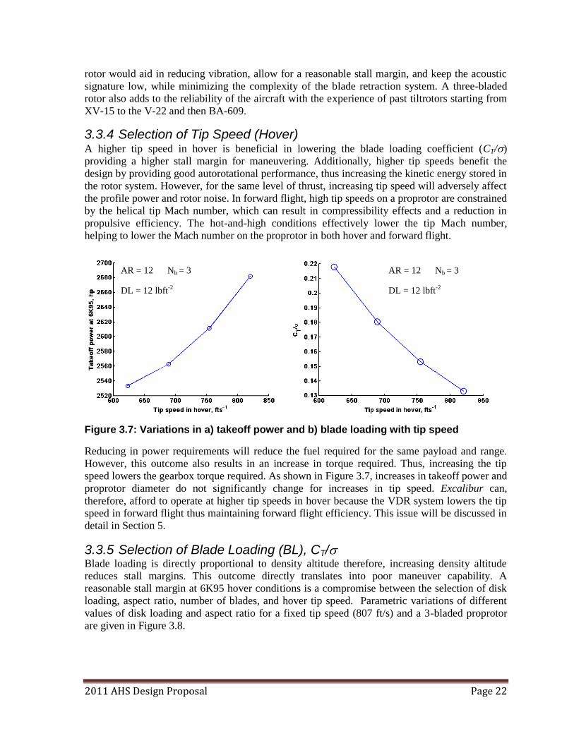
2011 AHS Design Proposal Page 22
rotor would aid in reducing vibration, allow for a reasonable stall margin, and keep the acoustic
signature low, while minimizing the complexity of the blade retraction system. A three-bladed
rotor also adds to the reliability of the aircraft with the experience of past tiltrotors starting from
XV-15 to the V-22 and then BA-609.
3.3.4 Selection of Tip Speed (Hover) A higher tip speed in hover is beneficial in lowering the blade loading coefficient (CT/)
providing a higher stall margin for maneuvering. Additionally, higher tip speeds benefit the
design by providing good autorotational performance, thus increasing the kinetic energy stored in
the rotor system. However, for the same level of thrust, increasing tip speed will adversely affect
the profile power and rotor noise. In forward flight, high tip speeds on a proprotor are constrained
by the helical tip Mach number, which can result in compressibility effects and a reduction in
propulsive efficiency. The hot-and-high conditions effectively lower the tip Mach number,
helping to lower the Mach number on the proprotor in both hover and forward flight.
Figure 3.7: Variations in a) takeoff power and b) blade loading with tip speed
Reducing in power requirements will reduce the fuel required for the same payload and range.
However, this outcome also results in an increase in torque required. Thus, increasing the tip
speed lowers the gearbox torque required. As shown in Figure 3.7, increases in takeoff power and
proprotor diameter do not significantly change for increases in tip speed. Excalibur can,
therefore, afford to operate at higher tip speeds in hover because the VDR system lowers the tip
speed in forward flight thus maintaining forward flight efficiency. This issue will be discussed in
detail in Section 5.
3.3.5 Selection of Blade Loading (BL), CT/ Blade loading is directly proportional to density altitude therefore, increasing density altitude
reduces stall margins. This outcome directly translates into poor maneuver capability. A
reasonable stall margin at 6K95 hover conditions is a compromise between the selection of disk
loading, aspect ratio, number of blades, and hover tip speed. Parametric variations of different
values of disk loading and aspect ratio for a fixed tip speed (807 ft/s) and a 3-bladed proprotor
are given in Figure 3.8.
AR = 12 Nb = 3
DL = 12 lbft-2
AR = 12 Nb = 3
DL = 12 lbft-2
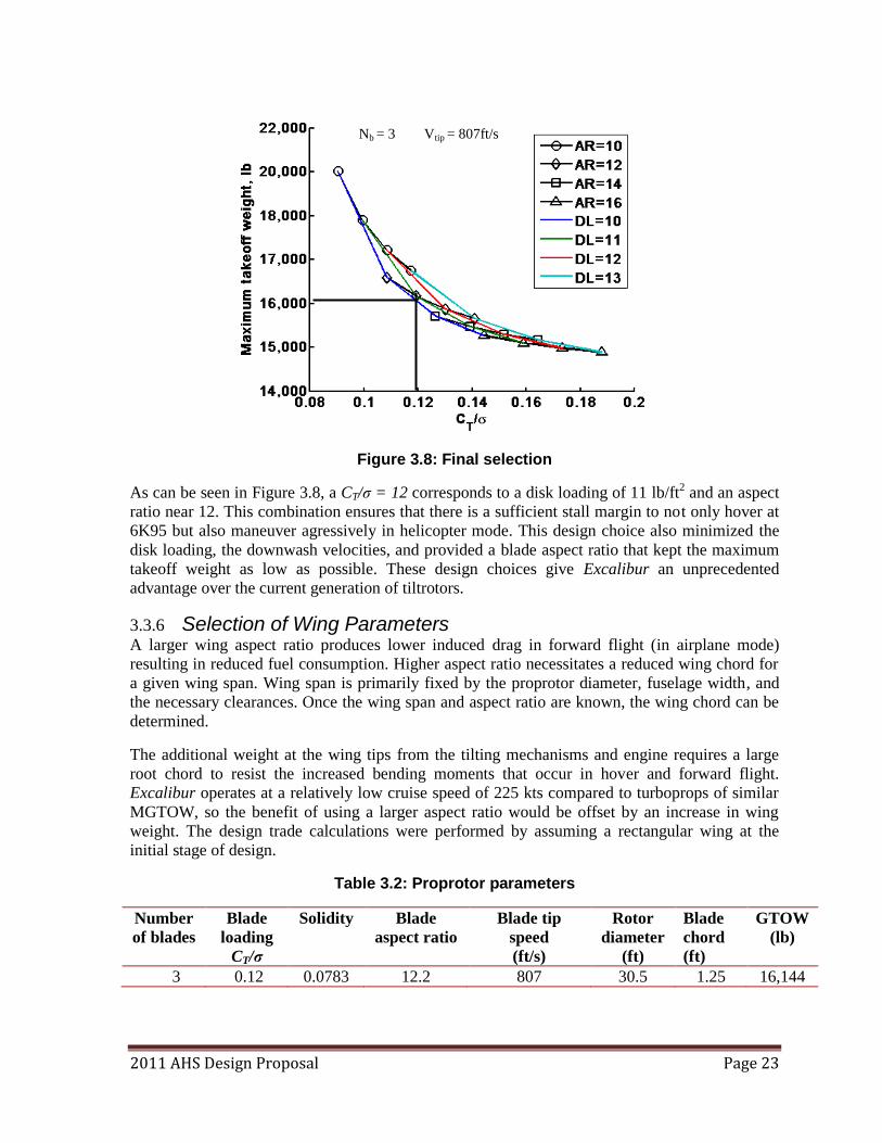
2011 AHS Design Proposal Page 23
Figure 3.8: Final selection
As can be seen in Figure 3.8, a CT/σ = 12 corresponds to a disk loading of 11 lb/ft2 and an aspect
ratio near 12. This combination ensures that there is a sufficient stall margin to not only hover at
6K95 but also maneuver agressively in helicopter mode. This design choice also minimized the
disk loading, the downwash velocities, and provided a blade aspect ratio that kept the maximum
takeoff weight as low as possible. These design choices give Excalibur an unprecedented
advantage over the current generation of tiltrotors.
3.3.6 Selection of Wing Parameters A larger wing aspect ratio produces lower induced drag in forward flight (in airplane mode)
resulting in reduced fuel consumption. Higher aspect ratio necessitates a reduced wing chord for
a given wing span. Wing span is primarily fixed by the proprotor diameter, fuselage width, and
the necessary clearances. Once the wing span and aspect ratio are known, the wing chord can be
determined.
The additional weight at the wing tips from the tilting mechanisms and engine requires a large
root chord to resist the increased bending moments that occur in hover and forward flight.
Excalibur operates at a relatively low cruise speed of 225 kts compared to turboprops of similar
MGTOW, so the benefit of using a larger aspect ratio would be offset by an increase in wing
weight. The design trade calculations were performed by assuming a rectangular wing at the
initial stage of design.
Table 3.2: Proprotor parameters
Number
of blades
Blade
loading
CT/σ
Solidity Blade
aspect ratio
Blade tip
speed
(ft/s)
Rotor
diameter
(ft)
Blade
chord
(ft)
GTOW
(lb)
3 0.12 0.0783 12.2 807 30.5 1.25 16,144
Nb = 3 Vtip = 807ft/s
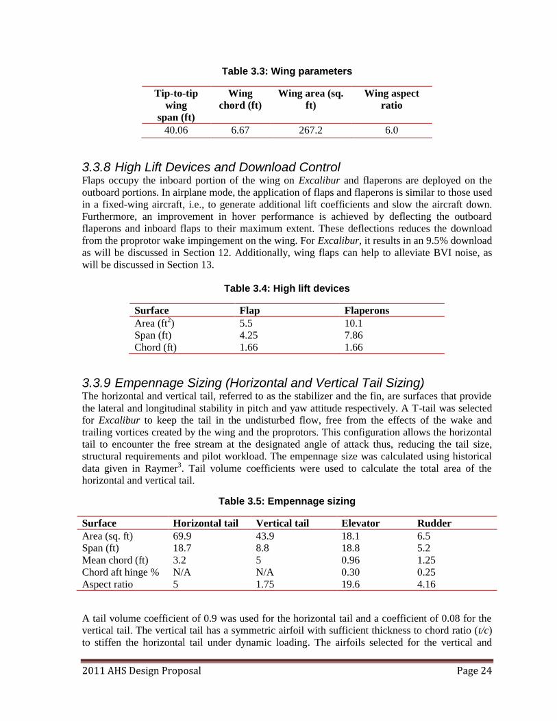
2011 AHS Design Proposal Page 24
Table 3.3: Wing parameters
Tip-to-tip
wing
span (ft)
Wing
chord (ft)
Wing area (sq.
ft)
Wing aspect
ratio
40.06 6.67 267.2 6.0
3.3.8 High Lift Devices and Download Control Flaps occupy the inboard portion of the wing on Excalibur and flaperons are deployed on the
outboard portions. In airplane mode, the application of flaps and flaperons is similar to those used
in a fixed-wing aircraft, i.e., to generate additional lift coefficients and slow the aircraft down.
Furthermore, an improvement in hover performance is achieved by deflecting the outboard
flaperons and inboard flaps to their maximum extent. These deflections reduces the download
from the proprotor wake impingement on the wing. For Excalibur, it results in an 9.5% download
as will be discussed in Section 12. Additionally, wing flaps can help to alleviate BVI noise, as
will be discussed in Section 13.
Table 3.4: High lift devices
Surface Flap Flaperons
Area (ft2) 5.5 10.1
Span (ft) 4.25 7.86
Chord (ft) 1.66 1.66
3.3.9 Empennage Sizing (Horizontal and Vertical Tail Sizing) The horizontal and vertical tail, referred to as the stabilizer and the fin, are surfaces that provide
the lateral and longitudinal stability in pitch and yaw attitude respectively. A T-tail was selected
for Excalibur to keep the tail in the undisturbed flow, free from the effects of the wake and
trailing vortices created by the wing and the proprotors. This configuration allows the horizontal
tail to encounter the free stream at the designated angle of attack thus, reducing the tail size,
structural requirements and pilot workload. The empennage size was calculated using historical
data given in Raymer3. Tail volume coefficients were used to calculate the total area of the
horizontal and vertical tail.
Table 3.5: Empennage sizing
Surface Horizontal tail Vertical tail Elevator Rudder
Area (sq. ft) 69.9 43.9 18.1 6.5
Span (ft) 18.7 8.8 18.8 5.2
Mean chord (ft) 3.2 5 0.96 1.25
Chord aft hinge % N/A N/A 0.30 0.25
Aspect ratio 5 1.75 19.6 4.16
A tail volume coefficient of 0.9 was used for the horizontal tail and a coefficient of 0.08 for the
vertical tail. The vertical tail has a symmetric airfoil with sufficient thickness to chord ratio (t/c)
to stiffen the horizontal tail under dynamic loading. The airfoils selected for the vertical and
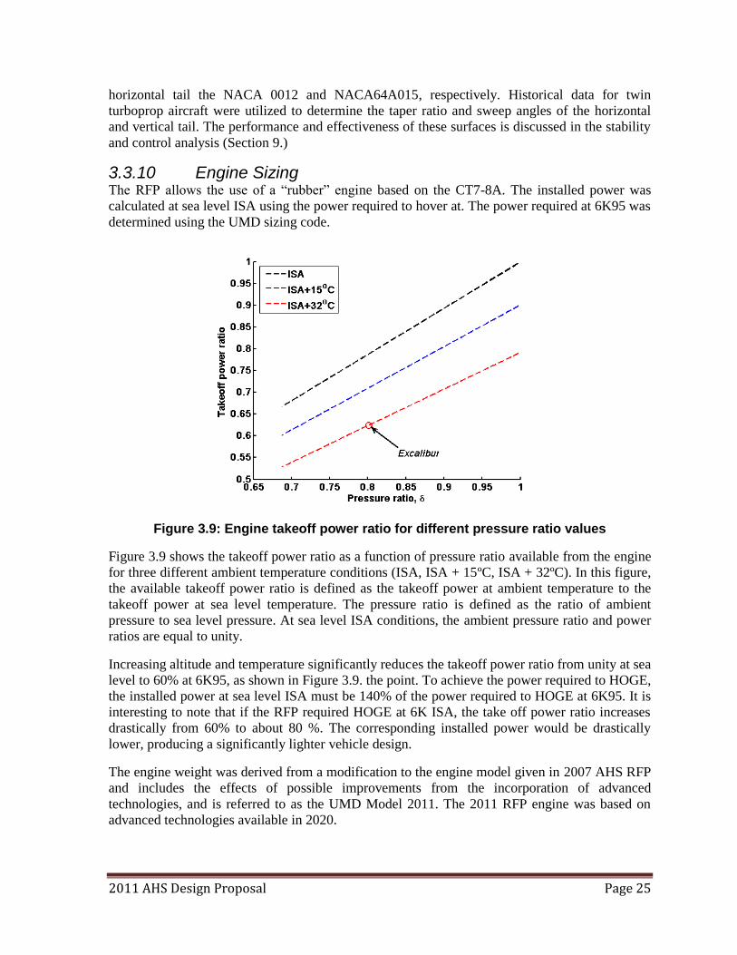
2011 AHS Design Proposal Page 25
horizontal tail the NACA 0012 and NACA64A015, respectively. Historical data for twin
turboprop aircraft were utilized to determine the taper ratio and sweep angles of the horizontal
and vertical tail. The performance and effectiveness of these surfaces is discussed in the stability
and control analysis (Section 9.)
3.3.10 Engine Sizing The RFP allows the use of a ―rubber‖ engine based on the CT7-8A. The installed power was
calculated at sea level ISA using the power required to hover at. The power required at 6K95 was
determined using the UMD sizing code.
Figure 3.9: Engine takeoff power ratio for different pressure ratio values
Figure 3.9 shows the takeoff power ratio as a function of pressure ratio available from the engine
for three different ambient temperature conditions (ISA, ISA + 15ºC, ISA + 32ºC). In this figure,
the available takeoff power ratio is defined as the takeoff power at ambient temperature to the
takeoff power at sea level temperature. The pressure ratio is defined as the ratio of ambient
pressure to sea level pressure. At sea level ISA conditions, the ambient pressure ratio and power
ratios are equal to unity.
Increasing altitude and temperature significantly reduces the takeoff power ratio from unity at sea
level to 60% at 6K95, as shown in Figure 3.9. the point. To achieve the power required to HOGE,
the installed power at sea level ISA must be 140% of the power required to HOGE at 6K95. It is
interesting to note that if the RFP required HOGE at 6K ISA, the take off power ratio increases
drastically from 60% to about 80 %. The corresponding installed power would be drastically
lower, producing a significantly lighter vehicle design.
The engine weight was derived from a modification to the engine model given in 2007 AHS RFP
and includes the effects of possible improvements from the incorporation of advanced
technologies, and is referred to as the UMD Model 2011. The 2011 RFP engine was based on
advanced technologies available in 2020.
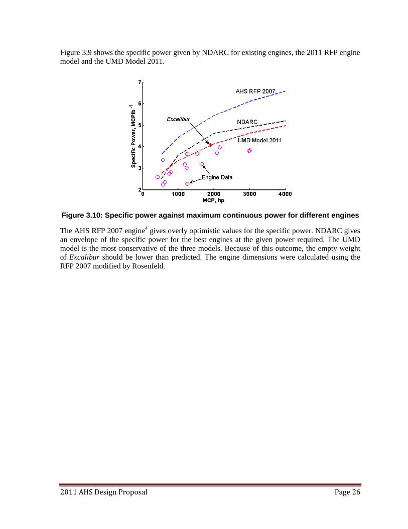
2011 AHS Design Proposal Page 26
Figure 3.9 shows the specific power given by NDARC for existing engines, the 2011 RFP engine
model and the UMD Model 2011.
Figure 3.10: Specific power against maximum continuous power for different engines
The AHS RFP 2007 engine4 gives overly optimistic values for the specific power. NDARC gives
an envelope of the specific power for the best engines at the given power required. The UMD
model is the most conservative of the three models. Because of this outcome, the empty weight
of Excalibur should be lower than predicted. The engine dimensions were calculated using the
RFP 2007 modified by Rosenfeld.
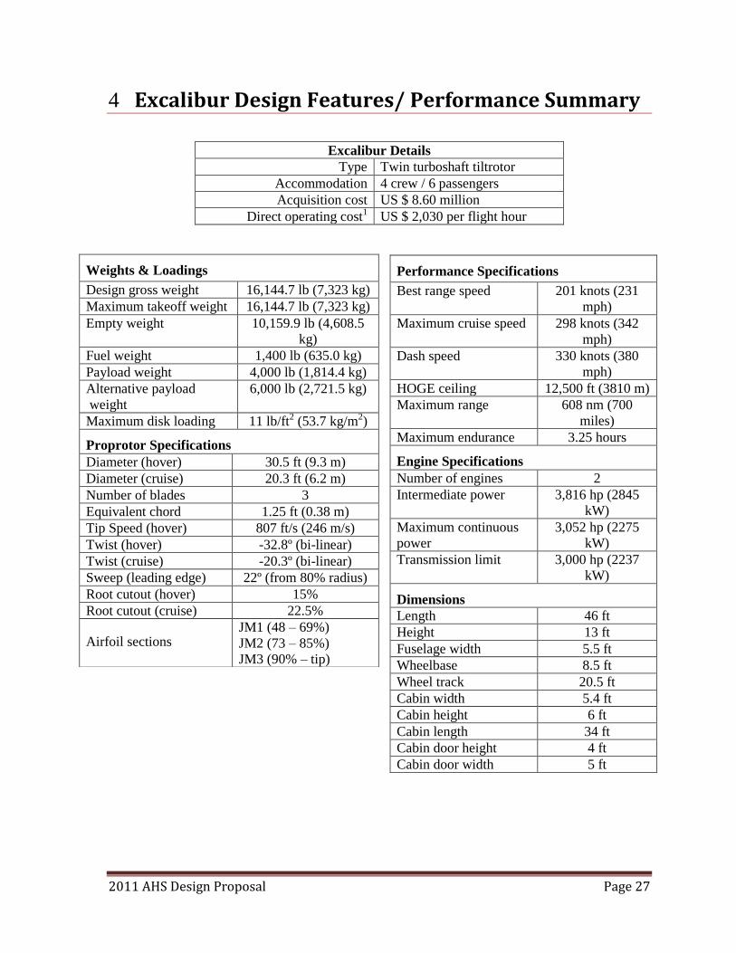
2011 AHS Design Proposal Page 27
4 Excalibur Design Features/ Performance Summary
Excalibur Details
Type Twin turboshaft tiltrotor
Accommodation 4 crew / 6 passengers
Acquisition cost US $ 8.60 million
Direct operating cost1 US $ 2,030 per flight hour
Weights & Loadings
Design gross weight 16,144.7 lb (7,323 kg)
Maximum takeoff weight 16,144.7 lb (7,323 kg)
Empty weight 10,159.9 lb (4,608.5
kg)
Fuel weight 1,400 lb (635.0 kg)
Payload weight 4,000 lb (1,814.4 kg)
Alternative payload
weight
6,000 lb (2,721.5 kg)
Maximum disk loading 11 lb/ft2 (53.7 kg/m2)
Proprotor Specifications
Diameter (hover) 30.5 ft (9.3 m)
Diameter (cruise) 20.3 ft (6.2 m)
Number of blades 3
Equivalent chord 1.25 ft (0.38 m)
Tip Speed (hover) 807 ft/s (246 m/s)
Twist (hover) -32.8º (bi-linear)
Twist (cruise) -20.3º (bi-linear)
Sweep (leading edge) 22º (from 80% radius)
Root cutout (hover) 15%
Root cutout (cruise) 22.5%
Airfoil sections JM1 (48 – 69%)
JM2 (73 – 85%)
JM3 (90% – tip)
Performance Specifications
Best range speed 201 knots (231
mph)
Maximum cruise speed 298 knots (342
mph)
Dash speed 330 knots (380
mph)
HOGE ceiling 12,500 ft (3810 m)
Maximum range 608 nm (700
miles)
Maximum endurance 3.25 hours
Engine Specifications
Number of engines 2
Intermediate power 3,816 hp (2845
kW)
Maximum continuous
power 3,052 hp (2275
kW)
Transmission limit 3,000 hp (2237
kW)
Dimensions
Length 46 ft
Height 13 ft
Fuselage width 5.5 ft
Wheelbase 8.5 ft
Wheel track 20.5 ft
Cabin width 5.4 ft
Cabin height 6 ft
Cabin length 34 ft
Cabin door height 4 ft
Cabin door width 5 ft
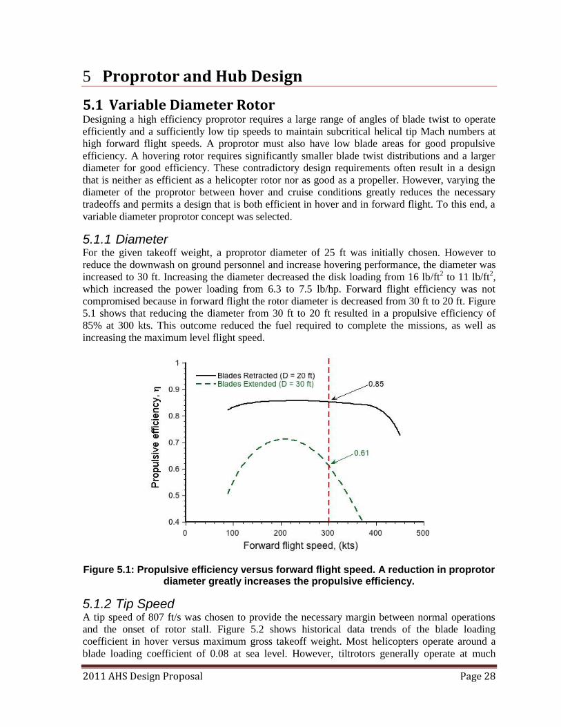
2011 AHS Design Proposal Page 28
5 Proprotor and Hub Design
5.1 Variable Diameter Rotor Designing a high efficiency proprotor requires a large range of angles of blade twist to operate
efficiently and a sufficiently low tip speeds to maintain subcritical helical tip Mach numbers at
high forward flight speeds. A proprotor must also have low blade areas for good propulsive
efficiency. A hovering rotor requires significantly smaller blade twist distributions and a larger
diameter for good efficiency. These contradictory design requirements often result in a design
that is neither as efficient as a helicopter rotor nor as good as a propeller. However, varying the
diameter of the proprotor between hover and cruise conditions greatly reduces the necessary
tradeoffs and permits a design that is both efficient in hover and in forward flight. To this end, a
variable diameter proprotor concept was selected.
5.1.1 Diameter For the given takeoff weight, a proprotor diameter of 25 ft was initially chosen. However to
reduce the downwash on ground personnel and increase hovering performance, the diameter was
increased to 30 ft. Increasing the diameter decreased the disk loading from 16 lb/ft2 to 11 lb/ft2,
which increased the power loading from 6.3 to 7.5 lb/hp. Forward flight efficiency was not
compromised because in forward flight the rotor diameter is decreased from 30 ft to 20 ft. Figure
5.1 shows that reducing the diameter from 30 ft to 20 ft resulted in a propulsive efficiency of
85% at 300 kts. This outcome reduced the fuel required to complete the missions, as well as
increasing the maximum level flight speed.
Figure 5.1: Propulsive efficiency versus forward flight speed. A reduction in proprotor diameter greatly increases the propulsive efficiency.
5.1.2 Tip Speed A tip speed of 807 ft/s was chosen to provide the necessary margin between normal operations
and the onset of rotor stall. Figure 5.2 shows historical data trends of the blade loading
coefficient in hover versus maximum gross takeoff weight. Most helicopters operate around a
blade loading coefficient of 0.08 at sea level. However, tiltrotors generally operate at much
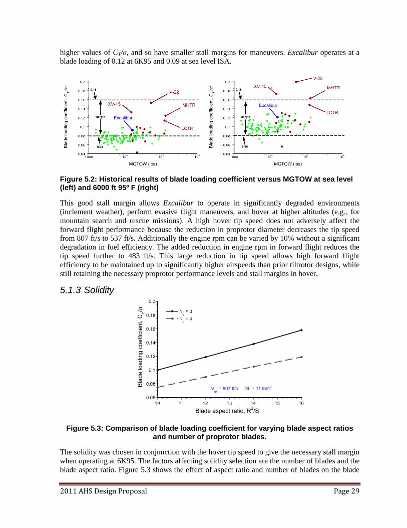
2011 AHS Design Proposal Page 29
higher values of CT/σ, and so have smaller stall margins for maneuvers. Excalibur operates at a
blade loading of 0.12 at 6K95 and 0.09 at sea level ISA.
Figure 5.2: Historical results of blade loading coefficient versus MGTOW at sea level (left) and 6000 ft 95º F (right)
This good stall margin allows Excalibur to operate in significantly degraded environments
(inclement weather), perform evasive flight maneuvers, and hover at higher altitudes (e.g., for
mountain search and rescue missions). A high hover tip speed does not adversely affect the
forward flight performance because the reduction in proprotor diameter decreases the tip speed
from 807 ft/s to 537 ft/s. Additionally the engine rpm can be varied by 10% without a significant
degradation in fuel efficiency. The added reduction in engine rpm in forward flight reduces the
tip speed further to 483 ft/s. This large reduction in tip speed allows high forward flight
efficiency to be maintained up to significantly higher airspeeds than prior tiltrotor designs, while
still retaining the necessary proprotor performance levels and stall margins in hover.
5.1.3 Solidity
Figure 5.3: Comparison of blade loading coefficient for varying blade aspect ratios and number of proprotor blades.
The solidity was chosen in conjunction with the hover tip speed to give the necessary stall margin
when operating at 6K95. The factors affecting solidity selection are the number of blades and the
blade aspect ratio. Figure 5.3 shows the effect of aspect ratio and number of blades on the blade
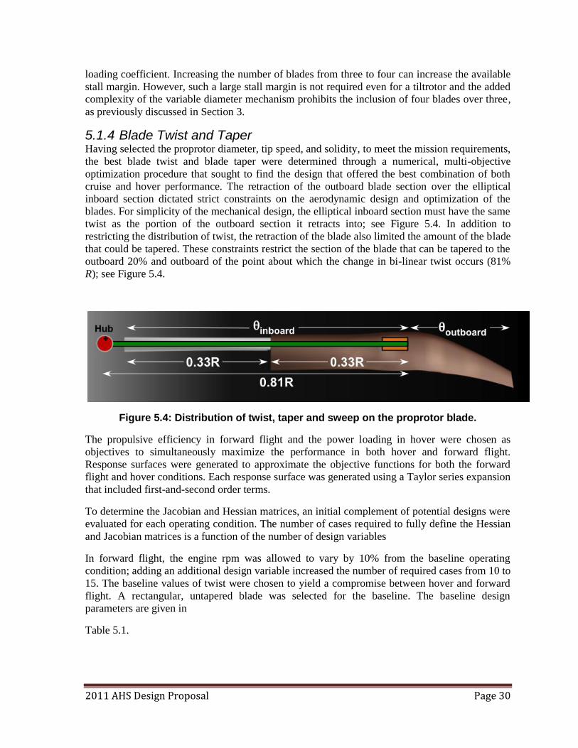
2011 AHS Design Proposal Page 30
loading coefficient. Increasing the number of blades from three to four can increase the available
stall margin. However, such a large stall margin is not required even for a tiltrotor and the added
complexity of the variable diameter mechanism prohibits the inclusion of four blades over three,
as previously discussed in Section 3.
5.1.4 Blade Twist and Taper Having selected the proprotor diameter, tip speed, and solidity, to meet the mission requirements,
the best blade twist and blade taper were determined through a numerical, multi-objective
optimization procedure that sought to find the design that offered the best combination of both
cruise and hover performance. The retraction of the outboard blade section over the elliptical
inboard section dictated strict constraints on the aerodynamic design and optimization of the
blades. For simplicity of the mechanical design, the elliptical inboard section must have the same
twist as the portion of the outboard section it retracts into; see Figure 5.4. In addition to
restricting the distribution of twist, the retraction of the blade also limited the amount of the blade
that could be tapered. These constraints restrict the section of the blade that can be tapered to the
outboard 20% and outboard of the point about which the change in bi-linear twist occurs (81%
R); see Figure 5.4.
Figure 5.4: Distribution of twist, taper and sweep on the proprotor blade.
The propulsive efficiency in forward flight and the power loading in hover were chosen as
objectives to simultaneously maximize the performance in both hover and forward flight.
Response surfaces were generated to approximate the objective functions for both the forward
flight and hover conditions. Each response surface was generated using a Taylor series expansion
that included first-and-second order terms.
To determine the Jacobian and Hessian matrices, an initial complement of potential designs were
evaluated for each operating condition. The number of cases required to fully define the Hessian
and Jacobian matrices is a function of the number of design variables
In forward flight, the engine rpm was allowed to vary by 10% from the baseline operating
condition; adding an additional design variable increased the number of required cases from 10 to
15. The baseline values of twist were chosen to yield a compromise between hover and forward
flight. A rectangular, untapered blade was selected for the baseline. The baseline design
parameters are given in
Table 5.1.
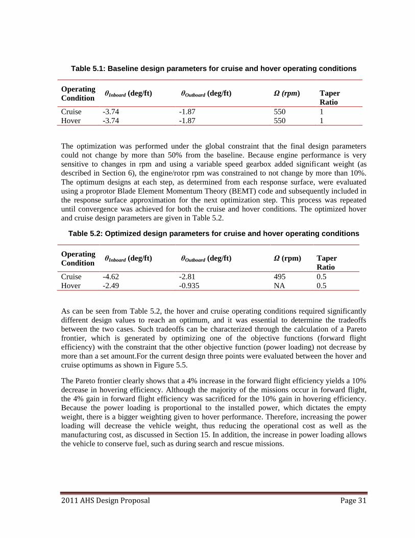
2011 AHS Design Proposal Page 31
Table 5.1: Baseline design parameters for cruise and hover operating conditions
Operating
Condition θInboard (deg/ft) θOutboard (deg/ft) Ω (rpm) Taper
Ratio
Cruise -3.74 -1.87 550 1
Hover -3.74 -1.87 550 1
The optimization was performed under the global constraint that the final design parameters
could not change by more than 50% from the baseline. Because engine performance is very
sensitive to changes in rpm and using a variable speed gearbox added significant weight (as
described in Section 6), the engine/rotor rpm was constrained to not change by more than 10%.
The optimum designs at each step, as determined from each response surface, were evaluated
using a proprotor Blade Element Momentum Theory (BEMT) code and subsequently included in
the response surface approximation for the next optimization step. This process was repeated
until convergence was achieved for both the cruise and hover conditions. The optimized hover
and cruise design parameters are given in Table 5.2.
Table 5.2: Optimized design parameters for cruise and hover operating conditions
Operating
Condition θInboard (deg/ft) θOutboard (deg/ft) Ω (rpm) Taper
Ratio
Cruise -4.62 -2.81 495 0.5
Hover -2.49 -0.935 NA 0.5
As can be seen from Table 5.2, the hover and cruise operating conditions required significantly
different design values to reach an optimum, and it was essential to determine the tradeoffs
between the two cases. Such tradeoffs can be characterized through the calculation of a Pareto
frontier, which is generated by optimizing one of the objective functions (forward flight
efficiency) with the constraint that the other objective function (power loading) not decrease by
more than a set amount.For the current design three points were evaluated between the hover and
cruise optimums as shown in Figure 5.5.
The Pareto frontier clearly shows that a 4% increase in the forward flight efficiency yields a 10%
decrease in hovering efficiency. Although the majority of the missions occur in forward flight,
the 4% gain in forward flight efficiency was sacrificed for the 10% gain in hovering efficiency.
Because the power loading is proportional to the installed power, which dictates the empty
weight, there is a bigger weighting given to hover performance. Therefore, increasing the power
loading will decrease the vehicle weight, thus reducing the operational cost as well as the
manufacturing cost, as discussed in Section 15. In addition, the increase in power loading allows
the vehicle to conserve fuel, such as during search and rescue missions.
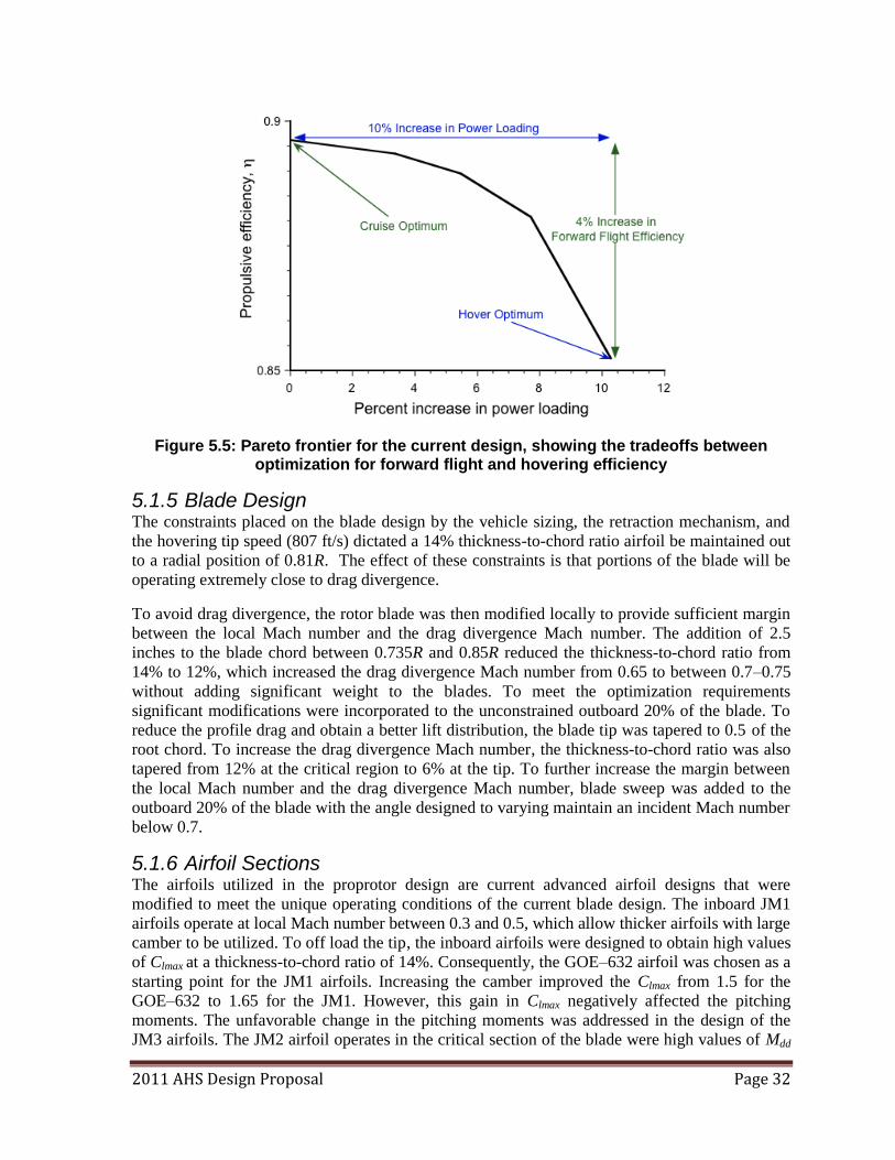
2011 AHS Design Proposal Page 32
Figure 5.5: Pareto frontier for the current design, showing the tradeoffs between optimization for forward flight and hovering efficiency
5.1.5 Blade Design The constraints placed on the blade design by the vehicle sizing, the retraction mechanism, and
the hovering tip speed (807 ft/s) dictated a 14% thickness-to-chord ratio airfoil be maintained out
to a radial position of 0.81R. The effect of these constraints is that portions of the blade will be
operating extremely close to drag divergence.
To avoid drag divergence, the rotor blade was then modified locally to provide sufficient margin
between the local Mach number and the drag divergence Mach number. The addition of 2.5
inches to the blade chord between 0.735R and 0.85R reduced the thickness-to-chord ratio from
14% to 12%, which increased the drag divergence Mach number from 0.65 to between 0.7–0.75
without adding significant weight to the blades. To meet the optimization requirements
significant modifications were incorporated to the unconstrained outboard 20% of the blade. To
reduce the profile drag and obtain a better lift distribution, the blade tip was tapered to 0.5 of the
root chord. To increase the drag divergence Mach number, the thickness-to-chord ratio was also
tapered from 12% at the critical region to 6% at the tip. To further increase the margin between
the local Mach number and the drag divergence Mach number, blade sweep was added to the
outboard 20% of the blade with the angle designed to varying maintain an incident Mach number
below 0.7.
5.1.6 Airfoil Sections The airfoils utilized in the proprotor design are current advanced airfoil designs that were
modified to meet the unique operating conditions of the current blade design. The inboard JM1
airfoils operate at local Mach number between 0.3 and 0.5, which allow thicker airfoils with large
camber to be utilized. To off load the tip, the inboard airfoils were designed to obtain high values
of Clmax at a thickness-to-chord ratio of 14%. Consequently, the GOE–632 airfoil was chosen as a
starting point for the JM1 airfoils. Increasing the camber improved the Clmax from 1.5 for the
GOE–632 to 1.65 for the JM1. However, this gain in Clmax negatively affected the pitching
moments. The unfavorable change in the pitching moments was addressed in the design of the
JM3 airfoils. The JM2 airfoil operates in the critical section of the blade were high values of Mdd
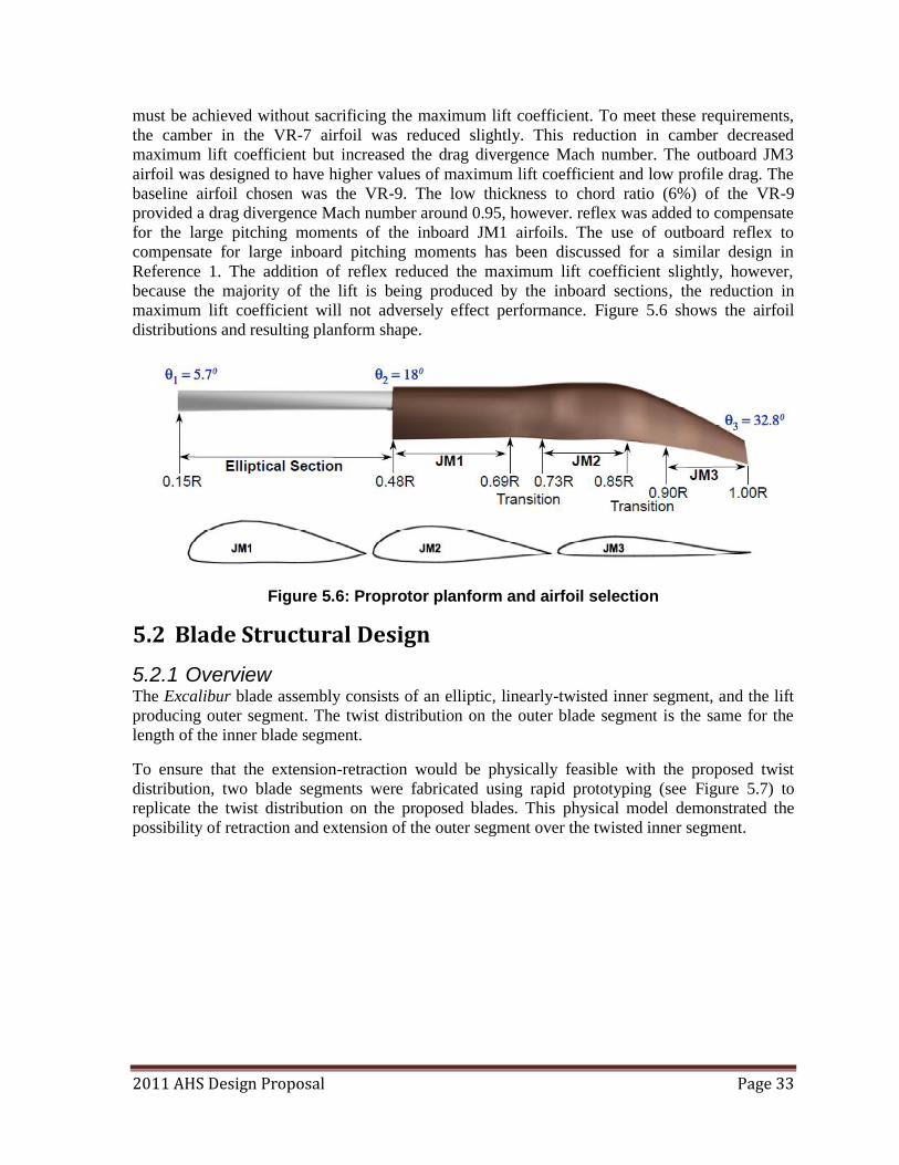
2011 AHS Design Proposal Page 33
must be achieved without sacrificing the maximum lift coefficient. To meet these requirements,
the camber in the VR-7 airfoil was reduced slightly. This reduction in camber decreased
maximum lift coefficient but increased the drag divergence Mach number. The outboard JM3
airfoil was designed to have higher values of maximum lift coefficient and low profile drag. The
baseline airfoil chosen was the VR-9. The low thickness to chord ratio (6%) of the VR-9
provided a drag divergence Mach number around 0.95, however. reflex was added to compensate
for the large pitching moments of the inboard JM1 airfoils. The use of outboard reflex to
compensate for large inboard pitching moments has been discussed for a similar design in
Reference 1. The addition of reflex reduced the maximum lift coefficient slightly, however,
because the majority of the lift is being produced by the inboard sections, the reduction in
maximum lift coefficient will not adversely effect performance. Figure 5.6 shows the airfoil
distributions and resulting planform shape.
Figure 5.6: Proprotor planform and airfoil selection
5.2 Blade Structural Design
5.2.1 Overview The Excalibur blade assembly consists of an elliptic, linearly-twisted inner segment, and the lift
producing outer segment. The twist distribution on the outer blade segment is the same for the
length of the inner blade segment.
To ensure that the extension-retraction would be physically feasible with the proposed twist
distribution, two blade segments were fabricated using rapid prototyping (see Figure 5.7) to
replicate the twist distribution on the proposed blades. This physical model demonstrated the
possibility of retraction and extension of the outer segment over the twisted inner segment.
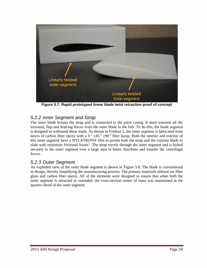
2011 AHS Design Proposal Page 34
Figure 5.7: Rapid prototyped linear blade twist retraction proof of concept
5.2.2 Inner Segment and Strap The inner blade houses the strap and is connected to the pitch casing. It must transmit all the
torsional, flap and lead-lag forces from the outer blade to the hub. To do this, the blade segment
is designed to withstand these loads. As shown in Foldout 2, the inner segment is fabricated from
layers of carbon fiber epoxy with a 0 o ±45 o ±90 o fiber layup. Both the interior and exterior of
this inner segment have a NYLATRON® film to permit both the strap and the exterior blade to
slide with minimum frictional losses1. The strap travels through the inner segment and is bolted
securely to the outer segment over a large area to better distribute and transfer the centrifugal
forces.
5.2.3 Outer Segment An exploded view of the outer blade segment is shown in Figure 5.8. The blade is conventional
in design, thereby simplifying the manufacturing process. The primary materials utilized are fiber
glass and carbon fiber epoxy. All of the elements were designed to ensure that when both the
inner segment is retracted or extended, the cross-section center of mass was maintained at the
quarter-chord of the outer segment.
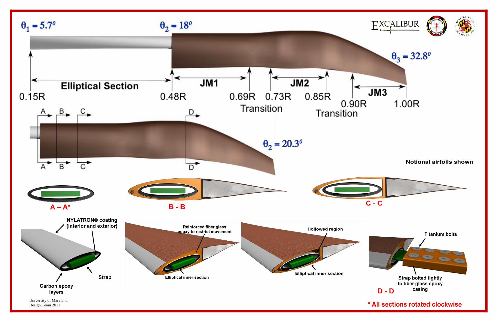
University of Maryland
Design Team 2011
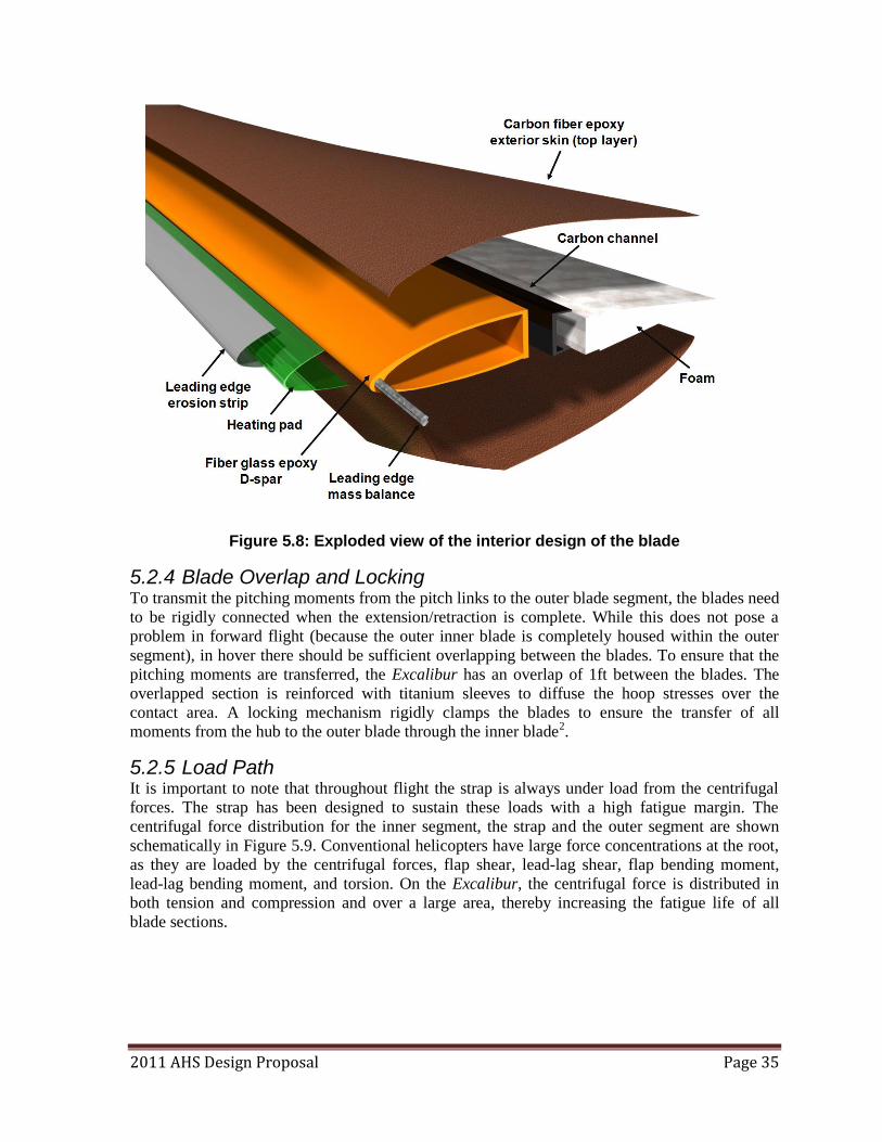
2011 AHS Design Proposal Page 35
Figure 5.8: Exploded view of the interior design of the blade
5.2.4 Blade Overlap and Locking To transmit the pitching moments from the pitch links to the outer blade segment, the blades need
to be rigidly connected when the extension/retraction is complete. While this does not pose a
problem in forward flight (because the outer inner blade is completely housed within the outer
segment), in hover there should be sufficient overlapping between the blades. To ensure that the
pitching moments are transferred, the Excalibur has an overlap of 1ft between the blades. The
overlapped section is reinforced with titanium sleeves to diffuse the hoop stresses over the
contact area. A locking mechanism rigidly clamps the blades to ensure the transfer of all
moments from the hub to the outer blade through the inner blade2.
5.2.5 Load Path It is important to note that throughout flight the strap is always under load from the centrifugal
forces. The strap has been designed to sustain these loads with a high fatigue margin. The
centrifugal force distribution for the inner segment, the strap and the outer segment are shown
schematically in Figure 5.9. Conventional helicopters have large force concentrations at the root,
as they are loaded by the centrifugal forces, flap shear, lead-lag shear, flap bending moment,
lead-lag bending moment, and torsion. On the Excalibur, the centrifugal force is distributed in
both tension and compression and over a large area, thereby increasing the fatigue life of all
blade sections.
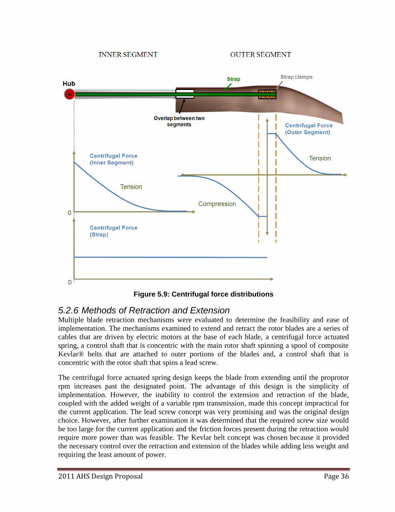
2011 AHS Design Proposal Page 36
Figure 5.9: Centrifugal force distributions
5.2.6 Methods of Retraction and Extension Multiple blade retraction mechanisms were evaluated to determine the feasibility and ease of
implementation. The mechanisms examined to extend and retract the rotor blades are a series of
cables that are driven by electric motors at the base of each blade, a centrifugal force actuated
spring, a control shaft that is concentric with the main rotor shaft spinning a spool of composite
Kevlar® belts that are attached to outer portions of the blades and, a control shaft that is
concentric with the rotor shaft that spins a lead screw.
The centrifugal force actuated spring design keeps the blade from extending until the proprotor
rpm increases past the designated point. The advantage of this design is the simplicity of
implementation. However, the inability to control the extension and retraction of the blade,
coupled with the added weight of a variable rpm transmission, made this concept impractical for
the current application. The lead screw concept was very promising and was the original design
choice. However, after further examination it was determined that the required screw size would
be too large for the current application and the friction forces present during the retraction would
require more power than was feasible. The Kevlar belt concept was chosen because it provided
the necessary control over the retraction and extension of the blades while adding less weight and
requiring the least amount of power.
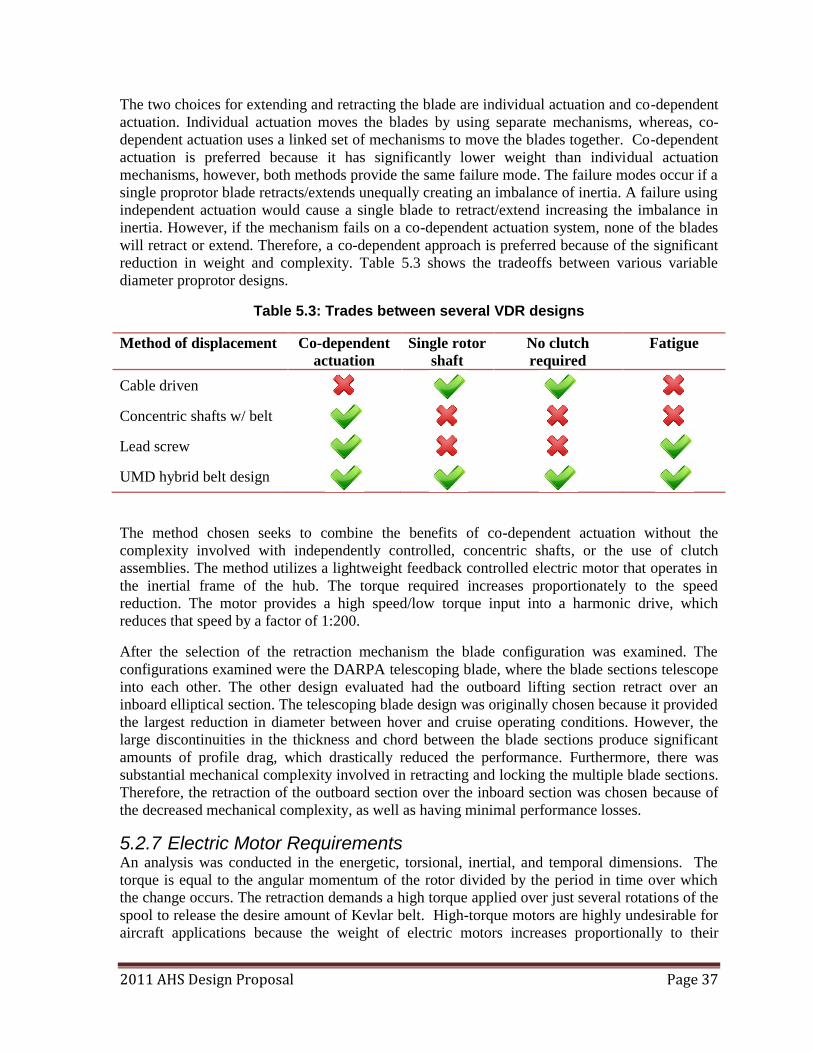
2011 AHS Design Proposal Page 37
The two choices for extending and retracting the blade are individual actuation and co-dependent
actuation. Individual actuation moves the blades by using separate mechanisms, whereas, co-
dependent actuation uses a linked set of mechanisms to move the blades together. Co-dependent
actuation is preferred because it has significantly lower weight than individual actuation
mechanisms, however, both methods provide the same failure mode. The failure modes occur if a
single proprotor blade retracts/extends unequally creating an imbalance of inertia. A failure using
independent actuation would cause a single blade to retract/extend increasing the imbalance in
inertia. However, if the mechanism fails on a co-dependent actuation system, none of the blades
will retract or extend. Therefore, a co-dependent approach is preferred because of the significant
reduction in weight and complexity. Table 5.3 shows the tradeoffs between various variable
diameter proprotor designs.
Table 5.3: Trades between several VDR designs
Method of displacement Co-dependent
actuation
Single rotor
shaft
No clutch
required
Fatigue
Cable driven
Concentric shafts w/ belt
Lead screw
UMD hybrid belt design
The method chosen seeks to combine the benefits of co-dependent actuation without the
complexity involved with independently controlled, concentric shafts, or the use of clutch
assemblies. The method utilizes a lightweight feedback controlled electric motor that operates in
the inertial frame of the hub. The torque required increases proportionately to the speed
reduction. The motor provides a high speed/low torque input into a harmonic drive, which
reduces that speed by a factor of 1:200.
After the selection of the retraction mechanism the blade configuration was examined. The
configurations examined were the DARPA telescoping blade, where the blade sections telescope
into each other. The other design evaluated had the outboard lifting section retract over an
inboard elliptical section. The telescoping blade design was originally chosen because it provided
the largest reduction in diameter between hover and cruise operating conditions. However, the
large discontinuities in the thickness and chord between the blade sections produce significant
amounts of profile drag, which drastically reduced the performance. Furthermore, there was
substantial mechanical complexity involved in retracting and locking the multiple blade sections.
Therefore, the retraction of the outboard section over the inboard section was chosen because of
the decreased mechanical complexity, as well as having minimal performance losses.
5.2.7 Electric Motor Requirements An analysis was conducted in the energetic, torsional, inertial, and temporal dimensions. The
torque is equal to the angular momentum of the rotor divided by the period in time over which
the change occurs. The retraction demands a high torque applied over just several rotations of the
spool to release the desire amount of Kevlar belt. High-torque motors are highly undesirable for
aircraft applications because the weight of electric motors increases proportionally to their
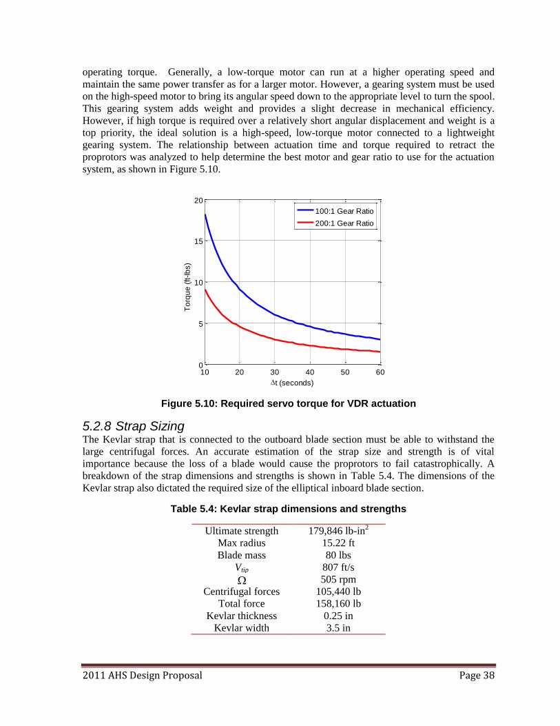
2011 AHS Design Proposal Page 38
operating torque. Generally, a low-torque motor can run at a higher operating speed and
maintain the same power transfer as for a larger motor. However, a gearing system must be used
on the high-speed motor to bring its angular speed down to the appropriate level to turn the spool.
This gearing system adds weight and provides a slight decrease in mechanical efficiency.
However, if high torque is required over a relatively short angular displacement and weight is a
top priority, the ideal solution is a high-speed, low-torque motor connected to a lightweight
gearing system. The relationship between actuation time and torque required to retract the
proprotors was analyzed to help determine the best motor and gear ratio to use for the actuation
system, as shown in Figure 5.10.
Figure 5.10: Required servo torque for VDR actuation
5.2.8 Strap Sizing The Kevlar strap that is connected to the outboard blade section must be able to withstand the
large centrifugal forces. An accurate estimation of the strap size and strength is of vital
importance because the loss of a blade would cause the proprotors to fail catastrophically. A
breakdown of the strap dimensions and strengths is shown in Table 5.4. The dimensions of the
Kevlar strap also dictated the required size of the elliptical inboard blade section.
Table 5.4: Kevlar strap dimensions and strengths
Ultimate strength 179,846 lb-in2
Max radius 15.22 ft
Blade mass 80 lbs
Vtip 807 ft/s
505 rpm
Centrifugal forces 105,440 lb
Total force 158,160 lb
Kevlar thickness 0.25 in
Kevlar width 3.5 in
10 20 30 40 50 600
5
10
15
20
t (seconds)
To
rqu
e (
ft-lb
s)
100:1 Gear Ratio
200:1 Gear Ratio
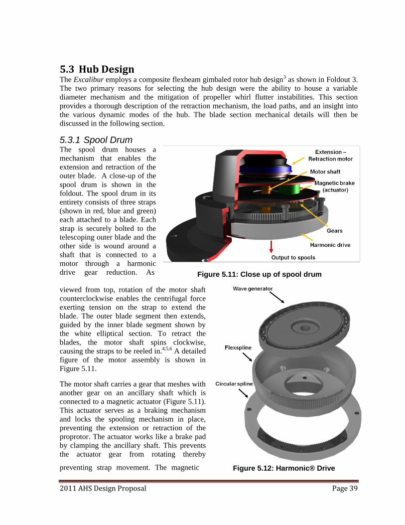
2011 AHS Design Proposal Page 39
5.3 Hub Design The Excalibur employs a composite flexbeam gimbaled rotor hub design3 as shown in Foldout 3.
The two primary reasons for selecting the hub design were the ability to house a variable
diameter mechanism and the mitigation of propeller whirl flutter instabilities. This section
provides a thorough description of the retraction mechanism, the load paths, and an insight into
the various dynamic modes of the hub. The blade section mechanical details will then be
discussed in the following section.
5.3.1 Spool Drum The spool drum houses a
mechanism that enables the
extension and retraction of the
outer blade. A close-up of the
spool drum is shown in the
foldout. The spool drum in its
entirety consists of three straps
(shown in red, blue and green)
each attached to a blade. Each
strap is securely bolted to the
telescoping outer blade and the
other side is wound around a
shaft that is connected to a
motor through a harmonic
drive gear reduction. As
viewed from top, rotation of the motor shaft
counterclockwise enables the centrifugal force
exerting tension on the strap to extend the
blade. The outer blade segment then extends,
guided by the inner blade segment shown by
the white elliptical section. To retract the
blades, the motor shaft spins clockwise,
causing the straps to be reeled in.4,5,6 A detailed
figure of the motor assembly is shown in
Figure 5.11.
The motor shaft carries a gear that meshes with
another gear on an ancillary shaft which is
connected to a magnetic actuator (Figure 5.11).
This actuator serves as a braking mechanism
and locks the spooling mechanism in place,
preventing the extension or retraction of the
proprotor. The actuator works like a brake pad
by clamping the ancillary shaft. This prevents
the actuator gear from rotating thereby
preventing strap movement. The magnetic
Figure 5.11: Close up of spool drum
Figure 5.12: Harmonic® Drive
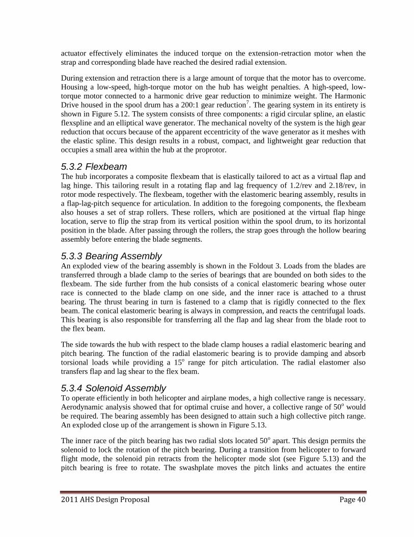
2011 AHS Design Proposal Page 40
actuator effectively eliminates the induced torque on the extension-retraction motor when the
strap and corresponding blade have reached the desired radial extension.
During extension and retraction there is a large amount of torque that the motor has to overcome.
Housing a low-speed, high-torque motor on the hub has weight penalties. A high-speed, low-
torque motor connected to a harmonic drive gear reduction to minimize weight. The Harmonic
Drive housed in the spool drum has a 200:1 gear reduction7. The gearing system in its entirety is
shown in Figure 5.12. The system consists of three components: a rigid circular spline, an elastic
flexspline and an elliptical wave generator. The mechanical novelty of the system is the high gear
reduction that occurs because of the apparent eccentricity of the wave generator as it meshes with
the elastic spline. This design results in a robust, compact, and lightweight gear reduction that
occupies a small area within the hub at the proprotor.
5.3.2 Flexbeam The hub incorporates a composite flexbeam that is elastically tailored to act as a virtual flap and
lag hinge. This tailoring result in a rotating flap and lag frequency of 1.2/rev and 2.18/rev, in
rotor mode respectively. The flexbeam, together with the elastomeric bearing assembly, results in
a flap-lag-pitch sequence for articulation. In addition to the foregoing components, the flexbeam
also houses a set of strap rollers. These rollers, which are positioned at the virtual flap hinge
location, serve to flip the strap from its vertical position within the spool drum, to its horizontal
position in the blade. After passing through the rollers, the strap goes through the hollow bearing
assembly before entering the blade segments.
5.3.3 Bearing Assembly An exploded view of the bearing assembly is shown in the Foldout 3. Loads from the blades are
transferred through a blade clamp to the series of bearings that are bounded on both sides to the
flexbeam. The side further from the hub consists of a conical elastomeric bearing whose outer
race is connected to the blade clamp on one side, and the inner race is attached to a thrust
bearing. The thrust bearing in turn is fastened to a clamp that is rigidly connected to the flex
beam. The conical elastomeric bearing is always in compression, and reacts the centrifugal loads.
This bearing is also responsible for transferring all the flap and lag shear from the blade root to
the flex beam.
The side towards the hub with respect to the blade clamp houses a radial elastomeric bearing and
pitch bearing. The function of the radial elastomeric bearing is to provide damping and absorb
torsional loads while providing a 15o range for pitch articulation. The radial elastomer also
transfers flap and lag shear to the flex beam.
5.3.4 Solenoid Assembly To operate efficiently in both helicopter and airplane modes, a high collective range is necessary.
Aerodynamic analysis showed that for optimal cruise and hover, a collective range of 50o would
be required. The bearing assembly has been designed to attain such a high collective pitch range.
An exploded close up of the arrangement is shown in Figure 5.13.
The inner race of the pitch bearing has two radial slots located 50o apart. This design permits the
solenoid to lock the rotation of the pitch bearing. During a transition from helicopter to forward
flight mode, the solenoid pin retracts from the helicopter mode slot (see Figure 5.13) and the
pitch bearing is free to rotate. The swashplate moves the pitch links and actuates the entire
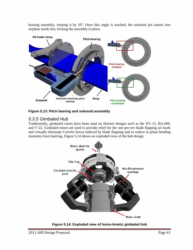
2011 AHS Design Proposal Page 41
bearing assembly, rotating it by 50o. Once this angle is reached, the solenoid pin inserts into
airplane mode slot, locking the assembly in place.
Figure 5.13: Pitch bearing and solenoid assembly
5.3.5 Gimbaled Hub Traditionally, gimbaled rotors have been used on tiltrotor designs such as the XV-15, BA-609,
and V-22. Gimbaled rotors are used to provide relief for the one-per-rev blade flapping air loads
and virtually eliminate Coriolis forces induced by blade flapping and so reduce in-plane bending
moments from lead-lag. Figure 5.14 shows an exploded view of the hub design.
Figure 5.14: Exploded view of homo-kinetic gimbaled hub
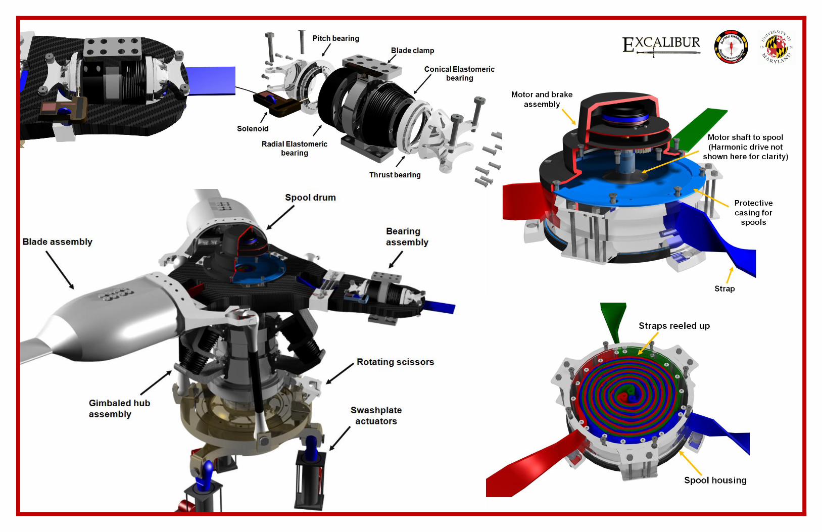
University of Maryland
Design Team 2011
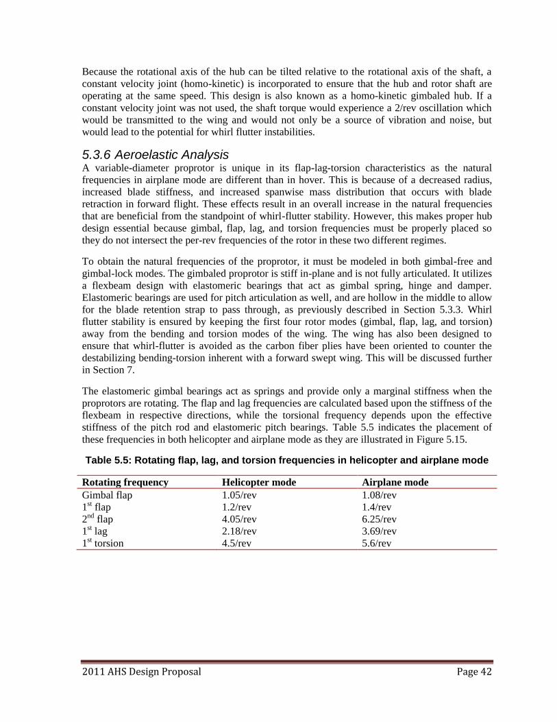
2011 AHS Design Proposal Page 42
Because the rotational axis of the hub can be tilted relative to the rotational axis of the shaft, a
constant velocity joint (homo-kinetic) is incorporated to ensure that the hub and rotor shaft are
operating at the same speed. This design is also known as a homo-kinetic gimbaled hub. If a
constant velocity joint was not used, the shaft torque would experience a 2/rev oscillation which
would be transmitted to the wing and would not only be a source of vibration and noise, but
would lead to the potential for whirl flutter instabilities.
5.3.6 Aeroelastic Analysis A variable-diameter proprotor is unique in its flap-lag-torsion characteristics as the natural
frequencies in airplane mode are different than in hover. This is because of a decreased radius,
increased blade stiffness, and increased spanwise mass distribution that occurs with blade
retraction in forward flight. These effects result in an overall increase in the natural frequencies
that are beneficial from the standpoint of whirl-flutter stability. However, this makes proper hub
design essential because gimbal, flap, lag, and torsion frequencies must be properly placed so
they do not intersect the per-rev frequencies of the rotor in these two different regimes.
To obtain the natural frequencies of the proprotor, it must be modeled in both gimbal-free and
gimbal-lock modes. The gimbaled proprotor is stiff in-plane and is not fully articulated. It utilizes
a flexbeam design with elastomeric bearings that act as gimbal spring, hinge and damper.
Elastomeric bearings are used for pitch articulation as well, and are hollow in the middle to allow
for the blade retention strap to pass through, as previously described in Section 5.3.3. Whirl
flutter stability is ensured by keeping the first four rotor modes (gimbal, flap, lag, and torsion)
away from the bending and torsion modes of the wing. The wing has also been designed to
ensure that whirl-flutter is avoided as the carbon fiber plies have been oriented to counter the
destabilizing bending-torsion inherent with a forward swept wing. This will be discussed further
in Section 7.
The elastomeric gimbal bearings act as springs and provide only a marginal stiffness when the
proprotors are rotating. The flap and lag frequencies are calculated based upon the stiffness of the
flexbeam in respective directions, while the torsional frequency depends upon the effective
stiffness of the pitch rod and elastomeric pitch bearings. Table 5.5 indicates the placement of
these frequencies in both helicopter and airplane mode as they are illustrated in Figure 5.15.
Table 5.5: Rotating flap, lag, and torsion frequencies in helicopter and airplane mode
Rotating frequency Helicopter mode Airplane mode
Gimbal flap 1.05/rev 1.08/rev
1st flap 1.2/rev 1.4/rev
2nd flap 4.05/rev 6.25/rev
1st lag 2.18/rev 3.69/rev
1st torsion 4.5/rev 5.6/rev
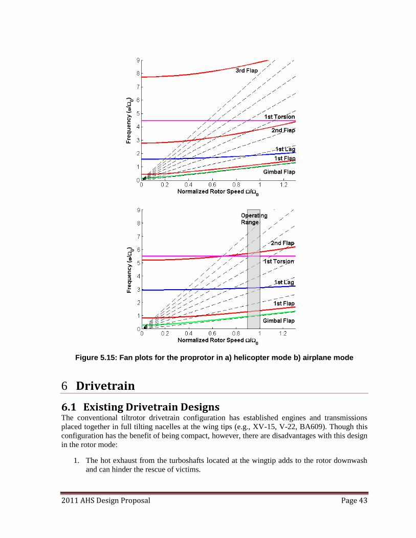
2011 AHS Design Proposal Page 43
Figure 5.15: Fan plots for the proprotor in a) helicopter mode b) airplane mode
6 Drivetrain
6.1 Existing Drivetrain Designs The conventional tiltrotor drivetrain configuration has established engines and transmissions
placed together in full tilting nacelles at the wing tips (e.g., XV-15, V-22, BA609). Though this
configuration has the benefit of being compact, however, there are disadvantages with this design
in the rotor mode:
1. The hot exhaust from the turboshafts located at the wingtip adds to the rotor downwash
and can hinder the rescue of victims.
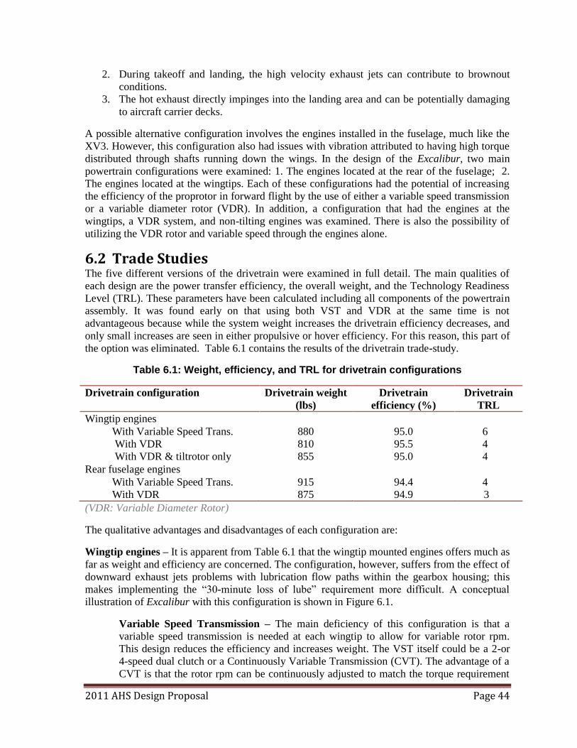
2011 AHS Design Proposal Page 44
2. During takeoff and landing, the high velocity exhaust jets can contribute to brownout
conditions.
3. The hot exhaust directly impinges into the landing area and can be potentially damaging
to aircraft carrier decks.
A possible alternative configuration involves the engines installed in the fuselage, much like the
XV3. However, this configuration also had issues with vibration attributed to having high torque
distributed through shafts running down the wings. In the design of the Excalibur, two main
powertrain configurations were examined: 1. The engines located at the rear of the fuselage; 2.
The engines located at the wingtips. Each of these configurations had the potential of increasing
the efficiency of the proprotor in forward flight by the use of either a variable speed transmission
or a variable diameter rotor (VDR). In addition, a configuration that had the engines at the
wingtips, a VDR system, and non-tilting engines was examined. There is also the possibility of
utilizing the VDR rotor and variable speed through the engines alone.
6.2 Trade Studies The five different versions of the drivetrain were examined in full detail. The main qualities of
each design are the power transfer efficiency, the overall weight, and the Technology Readiness
Level (TRL). These parameters have been calculated including all components of the powertrain
assembly. It was found early on that using both VST and VDR at the same time is not
advantageous because while the system weight increases the drivetrain efficiency decreases, and
only small increases are seen in either propulsive or hover efficiency. For this reason, this part of
the option was eliminated. Table 6.1 contains the results of the drivetrain trade-study.
Table 6.1: Weight, efficiency, and TRL for drivetrain configurations
Drivetrain configuration Drivetrain weight
(lbs)
Drivetrain
efficiency (%)
Drivetrain
TRL
Wingtip engines
With Variable Speed Trans. 880 95.0 6
With VDR 810 95.5 4
With VDR & tiltrotor only 855 95.0 4
Rear fuselage engines
With Variable Speed Trans. 915 94.4 4
With VDR 875 94.9 3
(VDR: Variable Diameter Rotor)
The qualitative advantages and disadvantages of each configuration are:
Wingtip engines – It is apparent from Table 6.1 that the wingtip mounted engines offers much as
far as weight and efficiency are concerned. The configuration, however, suffers from the effect of
downward exhaust jets problems with lubrication flow paths within the gearbox housing; this
makes implementing the ―30-minute loss of lube‖ requirement more difficult. A conceptual
illustration of Excalibur with this configuration is shown in Figure 6.1.
Variable Speed Transmission – The main deficiency of this configuration is that a
variable speed transmission is needed at each wingtip to allow for variable rotor rpm.
This design reduces the efficiency and increases weight. The VST itself could be a 2-or
4-speed dual clutch or a Continuously Variable Transmission (CVT). The advantage of a
CVT is that the rotor rpm can be continuously adjusted to match the torque requirement
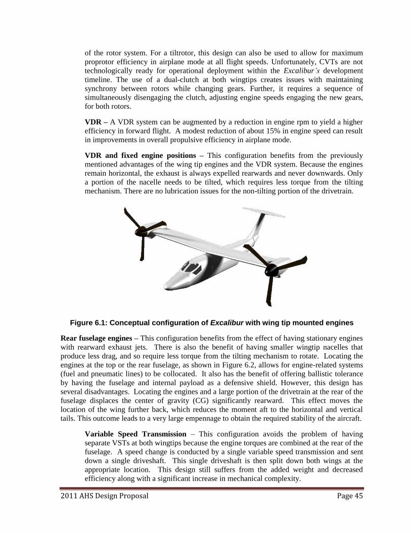
2011 AHS Design Proposal Page 45
of the rotor system. For a tiltrotor, this design can also be used to allow for maximum
proprotor efficiency in airplane mode at all flight speeds. Unfortunately, CVTs are not
technologically ready for operational deployment within the Excalibur’s development
timeline. The use of a dual-clutch at both wingtips creates issues with maintaining
synchrony between rotors while changing gears. Further, it requires a sequence of
simultaneously disengaging the clutch, adjusting engine speeds engaging the new gears,
for both rotors.
VDR – A VDR system can be augmented by a reduction in engine rpm to yield a higher
efficiency in forward flight. A modest reduction of about 15% in engine speed can result
in improvements in overall propulsive efficiency in airplane mode.
VDR and fixed engine positions – This configuration benefits from the previously
mentioned advantages of the wing tip engines and the VDR system. Because the engines
remain horizontal, the exhaust is always expelled rearwards and never downwards. Only
a portion of the nacelle needs to be tilted, which requires less torque from the tilting
mechanism. There are no lubrication issues for the non-tilting portion of the drivetrain.
Figure 6.1: Conceptual configuration of Excalibur with wing tip mounted engines
Rear fuselage engines – This configuration benefits from the effect of having stationary engines
with rearward exhaust jets. There is also the benefit of having smaller wingtip nacelles that
produce less drag, and so require less torque from the tilting mechanism to rotate. Locating the
engines at the top or the rear fuselage, as shown in Figure 6.2, allows for engine-related systems
(fuel and pneumatic lines) to be collocated. It also has the benefit of offering ballistic tolerance
by having the fuselage and internal payload as a defensive shield. However, this design has
several disadvantages. Locating the engines and a large portion of the drivetrain at the rear of the
fuselage displaces the center of gravity (CG) significantly rearward. This effect moves the
location of the wing further back, which reduces the moment aft to the horizontal and vertical
tails. This outcome leads to a very large empennage to obtain the required stability of the aircraft.
Variable Speed Transmission – This configuration avoids the problem of having
separate VSTs at both wingtips because the engine torques are combined at the rear of the
fuselage. A speed change is conducted by a single variable speed transmission and sent
down a single driveshaft. This single driveshaft is then split down both wings at the
appropriate location. This design still suffers from the added weight and decreased
efficiency along with a significant increase in mechanical complexity.
2011 AHS Design Proposal Page 46
VDR – This configuration benefits from the superior gain in efficiency during cruise and
hover. However, the added complexity and weight of overhead cabin shafts, redirection
gearboxes, and the addition of the variable diameter mechanism decreases the efficient
transfer of power and increases the empty weight.
Figure 6.2: Conceptual configuration with rear mounted engines
It is apparent that best configuration is wingtip mounted engines with a VDR system for
improved performance but with engine position fixed. This method provides an increase in
reliability and performance for the entire life of the vehicle.
6.3 Excalibur Drivetrain Overview The powertrain starts at the chosen turboshaft engines. The original equipment manufacturer
(OEM) gearbox allows a cost-effective, off-the-shelf speed reduction to a level that is
manageable to accommodate the interconnecting driveshaft stability and sprag clutch. The output
of the OEM gearbox is split between the interconnecting driveshaft, which maintains synchrony
between rotors, and the tilt-independent gearbox. The output from this gearbox is transferred into
a two stage epicyclic transmission that provides a 11.80:1 gear reduction. The final shaft torque,
speed, and tilt are transferred to the main rotor hub.
6.4 Drivetrain Description
6.4.1 UMD Turboshaft Engines The RFP requires that a ―rubber‖ engine be designed based on the CT7-8A turboshaft engine.
Following this, the engine selection has been done using the UMD engine model (see Section 3
for details). This selection was done to meet the project development timeline proposed by the
Team (see Section 15). The selected engine had a MSL power of 1,908 hp and weighs 376
pounds. Engine power and rotation rate are maintained by an onboard Full Authority Digital
Engine Control (FADEC) system, which tracks engine temperature, manifold pressure,
atmospheric conditions, and emissions, and adjusts engine operations accordingly.
The requirement that Excalibur meets all performance goals at 6K95 conditions represents a
significant challenge for the engine. The available engine power as a function of altitude and
temperature is shown in Figure 6.3.
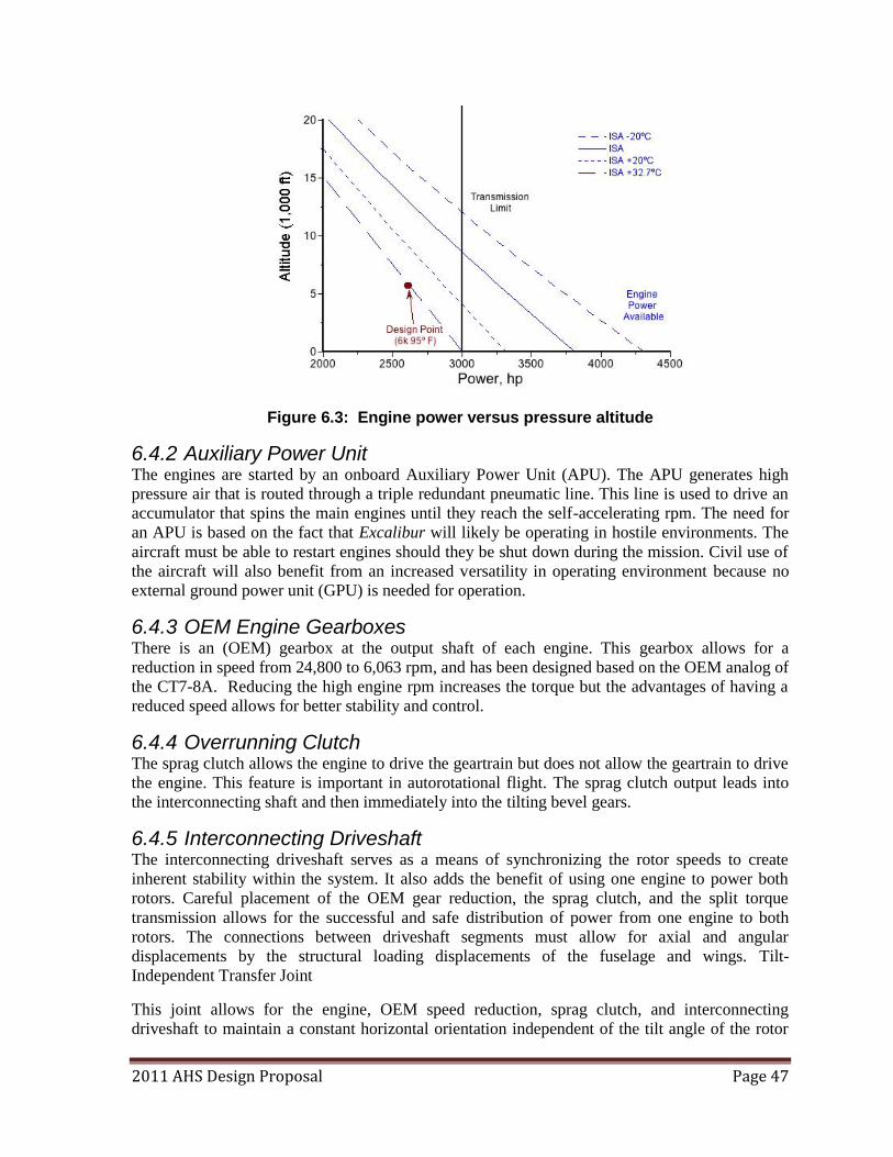
2011 AHS Design Proposal Page 47
Figure 6.3: Engine power versus pressure altitude
6.4.2 Auxiliary Power Unit The engines are started by an onboard Auxiliary Power Unit (APU). The APU generates high
pressure air that is routed through a triple redundant pneumatic line. This line is used to drive an
accumulator that spins the main engines until they reach the self-accelerating rpm. The need for
an APU is based on the fact that Excalibur will likely be operating in hostile environments. The
aircraft must be able to restart engines should they be shut down during the mission. Civil use of
the aircraft will also benefit from an increased versatility in operating environment because no
external ground power unit (GPU) is needed for operation.
6.4.3 OEM Engine Gearboxes There is an (OEM) gearbox at the output shaft of each engine. This gearbox allows for a
reduction in speed from 24,800 to 6,063 rpm, and has been designed based on the OEM analog of
the CT7-8A. Reducing the high engine rpm increases the torque but the advantages of having a
reduced speed allows for better stability and control.
6.4.4 Overrunning Clutch The sprag clutch allows the engine to drive the geartrain but does not allow the geartrain to drive
the engine. This feature is important in autorotational flight. The sprag clutch output leads into
the interconnecting shaft and then immediately into the tilting bevel gears.
6.4.5 Interconnecting Driveshaft The interconnecting driveshaft serves as a means of synchronizing the rotor speeds to create
inherent stability within the system. It also adds the benefit of using one engine to power both
rotors. Careful placement of the OEM gear reduction, the sprag clutch, and the split torque
transmission allows for the successful and safe distribution of power from one engine to both
rotors. The connections between driveshaft segments must allow for axial and angular
displacements by the structural loading displacements of the fuselage and wings. Tilt-
Independent Transfer Joint
This joint allows for the engine, OEM speed reduction, sprag clutch, and interconnecting
driveshaft to maintain a constant horizontal orientation independent of the tilt angle of the rotor
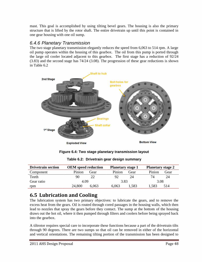
2011 AHS Design Proposal Page 48
mast. This goal is accomplished by using tilting bevel gears. The housing is also the primary
structure that is lifted by the rotor shaft. The entire drivetrain up until this point is contained in
one gear housing with one oil sump.
6.4.6 Planetary Transmission The two stage planetary transmission elegantly reduces the speed from 6,063 to 514 rpm. A large
oil pump operates within the housing of this gearbox. The oil from this pump is ported through
the large oil cooler located adjacent to this gearbox. The first stage has a reduction of 92/24
(3.83) and the second stage has 74/24 (3.08). The progression of these gear reductions is shown
in Table 6.2
Figure 6.4: Two stage planetary transmission layout
Table 6.2: Drivetrain gear design summary
Drivetrain section OEM speed reduction Planetary stage 1 Planetary stage 2
Component Pinion Gear Pinion Gear Pinion Gear
Teeth 90 22 92 24 74 24
Gear ratio 4.09 3.83 3.08
rpm 24,800 6,063 6,063 1,583 1,583 514
6.5 Lubrication and Cooling The lubrication system has two primary objectives: to lubricate the gears, and to remove the
excess heat from the gears. Oil is routed through cored passages in the housing walls, which then
lead to nozzles that spray the gears before they contact. The sump at the bottom of the housing
draws out the hot oil, where it then pumped through filters and coolers before being sprayed back
into the gearbox.
A tiltrotor requires special care to incorporate these functions because a part of the drivetrain tilts
through 90 degrees. There are two sumps so that oil can be removed in either of the horizontal
and vertical orientations. The remaining tilting portion of the transmission has been designed to
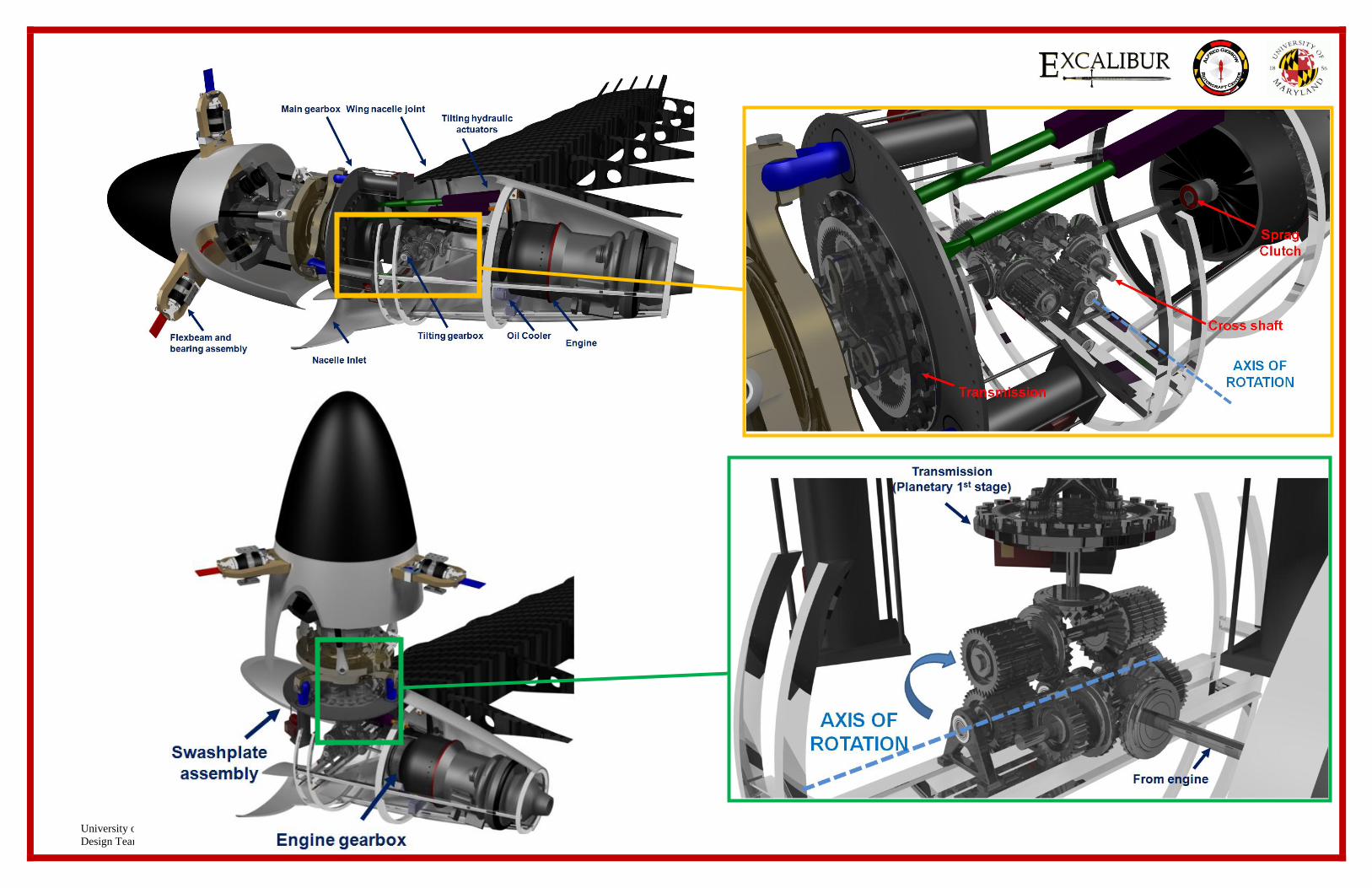
University of Maryland
Design Team 2011
2011 AHS Design Proposal Page 49
last 30 minutes after the loss of lubrication. Cells have been carved into the internal housing
walls to allow for oil to pool after the loss of lubrication. Once this oil is effectively being
recycled by the spinning gears, it is only a matter of time before the temperatures in the gearbox
begin to degrade not only the gear teeth, but also destroy the effectiveness of lubrication of the
oil that makes it useful for lubrication. Verification of the 30 minutes dry running capability must
be proved by testing of the Excalibur’s transmission.
The lubrication cooling system has been designed so that the exit temperature of the oil from any
gearbox is no more than 45°F above the entrance temperature. For any of the given gearbox a
single drop of oil may cycle through the lubrication system several times per minute. The OEM
gear boxes contain approximately 1 gallon of oil, and the two-stage planetary transmission
housing contains approximately 2 gallons of oil. Hot oil from either the tilting or non-tilting
gearbox is pumped through the multi-input-multi-output (MIMO) oil cooler located at the outer
edge of the wingtip nacelle. Redundancy of on oil cooler input and output path allows oil flow in
the event of single entrance or exit becoming blocked.
The oil pressure and temperature sensors have been placed in strategic locations throughout the
lubrication system. In addition magnetic chip detectors have been placed in the oil flow path. For
the portion of the drivetrain that tilts, detectors are located at the settling locations for both
horizontal and vertical orientations.
6.6 Alternator The power converter draws energy off of the powertrain at the intermediate gearbox. The
wattage of the alternator must meet the demands of the aircraft during peak power consumption,
as well as during normal operation.
7 Airframe Design
The Excalibur is designed to handle multiple missions in a military environment. Therefore,
Excalibur utilizes a compact, crashworthy airframe that is designed to meet the rigors of military
operations. The components used in the airframe design provide a modular internal layout,
ballistic protection, and a retractable landing gear system.
7.1.1 Wing Structure The sizing of structural members within the wing was determined based upon calculations of
shear force, bending, and torsion moments along the span of the wing. Wing components were
sized to ensure a sufficient margin to permit high-speed maneuvering flight. This section
discusses the structure of the wing and the reasoning for the configuration and sizes chosen.
The wing composite structure used on the Excalibur is shown in Figure 7.1 The wing structure is
fabricated from 35 layers of ±45o carbon epoxy to provide sufficient stiffness to prevent whirl
flutter and to have adequate strength to overcome the bending and torsion loads on the wing. In
addition, the torque box has layers of carbon/epoxy oriented at 15º to generate flap bending-twist
coupling. This coupling increases aeroelastic stability margins in forward flight.
The torque box is located along the chord from 0.07c to 0.45c. Because the wing has a 20%
thickness-to-chord ratio with a maximum thickness at 0.30c, the torque box has a large flap
stiffness and torsional stiffness.
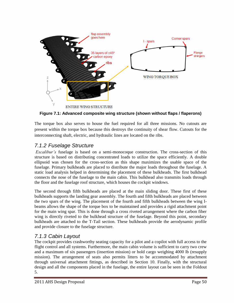
2011 AHS Design Proposal Page 50
Figure 7.1: Advanced composite wing structure (shown without flaps / flaperons)
The torque box also serves to house the fuel required for all three missions. No cutouts are
present within the torque box because this destroys the continuity of shear flow. Cutouts for the
interconnecting shaft, electric, and hydraulic lines are located on the ribs.
7.1.2 Fuselage Structure Excalibur’s fuselage is based on a semi-monocoque construction. The cross-section of this
structure is based on distributing concentrated loads to utilize the space efficiently. A double
ellipsoid was chosen for the cross-section as this shape maximizes the usable space of the
fuselage. Primary bulkheads are placed to distribute the major loads throughout the fuselage. A
static load analysis helped in determining the placement of these bulkheads. The first bulkhead
connects the nose of the fuselage to the main cabin. This bulkhead also transmits loads through
the floor and the fuselage roof structure, which houses the cockpit windows.
The second through fifth bulkheads are placed at the main sliding door. These first of these
bulkheads supports the landing gear assembly. The fourth and fifth bulkheads are placed between
the two spars of the wing. The placement of the fourth and fifth bulkheads between the wing I-
beams allows the shape of the torque box to be maintained and provides a rigid attachment point
for the main wing spar. This is done through a cross riveted arrangement where the carbon fiber
wing is directly riveted to the bulkhead structure of the fuselage. Beyond this point, secondary
bulkheads are attached to the T-Tail section. These bulkheads provide the aerodynamic profile
and provide closure to the fuselage structure.
7.1.3 Cabin Layout The cockpit provides crashworthy seating capacity for a pilot and a copilot with full access to the
flight control and all systems. Furthermore, the main cabin volume is sufficient to carry two crew
and a maximum of six passengers (insertion mission) or hold cargo weighing 4000 lb (resupply
mission). The arrangement of seats also permits litters to be accommodated by attachment
through universal attachment fittings, as described in Section 10. Finally, with the structural
design and all the components placed in the fuselage, the entire layout can be seen in the Foldout
5.
2011 AHS Design Proposal Page 51
The sliding doors used in Excalibur are jettisonable. A sliding design provides an optimized
solution between accessibility and maintaining structural integrity. This adds to the versatility of
Excalibur. The door is attached between the fifth and sixth bulkheads and is large enough for
easy loading/unloading of cargo and the maneuver of a rescue basket for search and rescue
missions. The overall size of the door is 4 ft by 5 ft.
The cockpit windows present on the cockpit of Excalibur offer vision for both the pilots and the
copilot. Another window is provided on the floor of Excalibur for the pilots to see the landing
area when descending in helicopter mode.
7.2 Structural Materials Selection of a material for aircraft construction depends on several factors specific to their
application. Some of the material properties to be considered include the yield and ultimate
strength, stiffness, fatigue resistance, corrosion resistance, manufacturability, ease of repair, cost,
and availability. More importantly, there has been recent emphasis on the use of environmental
friendly materials, reduced energy consumption, and lower life cycle costs.
Excalibur has been designed to have a balance between low cost, manufacturability,
maintainability and environmental friendliness. Excalibur will perform missions for military
applications and, therefore, will be subject to different weather conditions, varied loads,
unfriendly airspace, and other unknowns. These concerns lead to the need for a robust and
versatile airframe structure. The following section details the material selection and specifics for
major components of Excalibur.
Aluminum-Lithium (Al-Li) alloys are used for the construction of frames of the cabin of
Excalibur. Al-Li alloys drive the weight of the system down and can be formed using traditional
aluminum manufacturing techniques. Therefore, a commercially available alloy of Al-Li,
Weldalite 0409 is used. Weldalite 0409 is comprised of about 2% lithium, resulting in a 7%
reduction in density and a 10% increase in elastic modulus. Weldalite has an excellent strength to
weight ratio, resistance to chemical corrosion, fatigue resistance, and crack propagation
resistance. At the same time, however, this material demonstrates reduced fracture toughness and
ductility in the short transverse direction. On Excalibur, Weldalite 0409 is used on the primary
and secondary bulkheads and longerons. From a manufacturing perspective, it is easily weldable
and reduces the number of mechanical fasteners that can contribute to fatigue loads. This brings
down the production and maintenance cost of Excalibur’s primary structure.
Cabin floors need to be lightweight while maintaining the ability to carry large inertial loads.
Kevlar and nomex honeycomb was used for the floor to provide superior stiffness and abrasion
resistance.
The empennage structure (horizontal and vertical tail) is constructed using a composite
construction that makes it lightweight. The vertical stabilizer, rudder, horizontal stabilizer and
elevator use Kevlar/carbon/glass. The top layers of the vertical and horizontal stabilizer are made
of Kevlar/epoxy. This reduces the number of components and rivets by a factor of 20 as
compared with an equivalent metallic construction.
The rotor blades must be stiff enough to carry high centrifugal loads, and resists the oscillatory
flap, lead-lag, and torsional moments. Selecting suitable materials produces favorable structural
couplings. The blade for Excalibur principally consists of an envelope that ensures aerodynamic
2011 AHS Design Proposal Page 52
profile and stiffners to carry the large centrifugal forces. The spar is made of glass/epoxy.
Composite materials such as carbon fiber/epoxy are considered for the outer portion of the blades
and elliptic parts that are light, possess high stiffness to weight ratio, and good strength-to-weight
ratio. In addition, these materials have good damage tolerance properties, good ballistic
tolerance, and can be easily constructed and elastically tailored1. Nomex honeycomb is used as
the filler material to give rigidity to the skin. To allow for grounding of any electrical charge,
electrical bonding is achieved in the structure using an aluminum mesh.
The rotor hub assembly should allow for different degrees-of-freedom for the rotor blade. The
yoke of hub is made by use of balanced multilayer glass/epoxy fabric (0/+45/90) and molding it
in an autoclave. Major benefits of using this material are cost high stiffness, reduction, weight
reduction and most significantly, ease of maintenance. The elastomeric bearings present in the
rotor hub are made of alternating layers of steel and rubber to allow for movement through shear
of the rubber. These bearings are then coated with silicon to protect them the effects of oil and
ozone.
Two disadvantages of using rubber in the elastomeric bearings are that its stiffness is a function
of temperature. As the temperature decreases, its Young‘s modulus E and torsional rigidity G,
increases. This increase in stiffness would require higher forces to change the pitch of the rotor
blades on cold days. However, because rubber is a poor conductor of heat, the bearings usually
warm up after a few actuations, and the force required for actuation returns to normal levels.
Another disadvantage is that rubber deteriorates in the presence of ozone, therefore the bearings
are protected by a layer of silicone.
This material selection makes the rotor hub and blades tolerant to damage and to be able to
sustain damage for projectiles of less than 20 mm caliber.
Door: The cockpit doors are large sliding doors under the wing. These sliding doors are located
on both sides of the fuselage, and are wide enough to facilitate search and rescue operations and
litter embarkation. All doors are braced to prevent jamming in the event of airframe warping, and
can be jettisoned in emergencies as is required by 14 CFR 29.783.
Table 7.1 lists the different materials used during the manufacturing of Excalibur. The majority
of these materials will be available under our project development timeline.
In addition to strength-to-weight and operative cost benefits of composites, the extensive usage
of composite materials in Excalibur reduces its radar signature, as required by RFP. In
Excalibur’s design, adequate consideration has been made of the recyclability. Nearly all the
Aluminum alloys used in Excalibur are recyclable. Similarly a number of non-fatigue
components such as avionics, cabin flooring, furnishing equipment, etc. will be available for
direct reuse and do not require additional energy at the end of life cycle.
Excalibur’s airframe is both lightweight and highly environmentally friendly, and the choice of
materials allows the aircraft to be versatile.
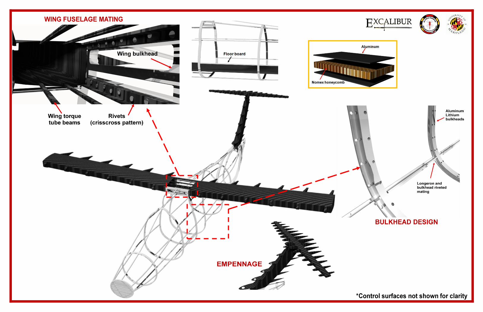
University of Maryland
Design Team 2011
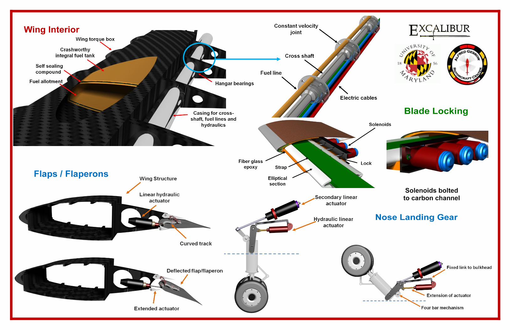
University of Maryland
Design Team 2011
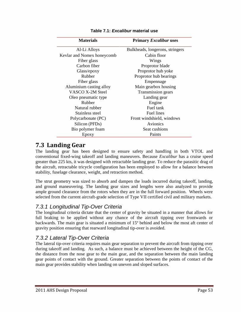
2011 AHS Design Proposal Page 53
Table 7.1: Excalibur material use
Materials Primary Excalibur uses
Al-Li Alloys Bulkheads, longerons, stringers
Kevlar and Nomex honeycomb Cabin floor
Fiber glass Wings
Carbon fiber Proprotor blade
Glass/epoxy Proprotor hub yoke
Rubber Proprotor hub bearings
Fiber glass Empennage
Aluminium casting alloy Main gearbox housing
VASCO X-2M Steel Transmission gears
Oleo pneumatic type Landing gear
Rubber Engine
Natural rubber Fuel tank
Stainless steel Fuel lines
Polycarbonate (PC) Front windshield, windows
Silicon (PFDs) Avionics
Bio polymer foam Seat cushions
Epoxy Paints
7.3 Landing Gear The landing gear has been designed to ensure safety and handling in both VTOL and
conventional fixed-wing takeoff and landing maneuvers. Because Excalibur has a cruise speed
greater than 225 kts, it was designed with retractable landing gear. To reduce the parasitic drag of
the aircraft, retractable tricycle configuration has been employed to allow for a balance between
stability, fuselage clearance, weight, and retraction method.
The strut geometry was sized to absorb and dampen the loads incurred during takeoff, landing,
and ground maneuvering. The landing gear sizes and lengths were also analyzed to provide
ample ground clearance from the rotors when they are in the full forward position. Wheels were
selected from the current aircraft-grade selection of Type VII certified civil and military markets.
7.3.1 Longitudinal Tip-Over Criteria The longitudinal criteria dictate that the center of gravity be situated in a manner that allows for
full braking to be applied without any chance of the aircraft tipping over frontwards or
backwards. The main gear is situated a minimum of 15º behind and below the most aft center of
gravity position ensuring that rearward longitudinal tip-over is avoided.
7.3.2 Lateral Tip-Over Criteria The lateral tip-over criteria requires main gear separation to prevent the aircraft from tipping over
during takeoff and landing. As such, a balance must be achieved between the height of the CG,
the distance from the nose gear to the main gear, and the separation between the main landing
gear points of contact with the ground. Greater separation between the points of contact of the
main gear provides stability when landing on uneven and sloped surfaces.
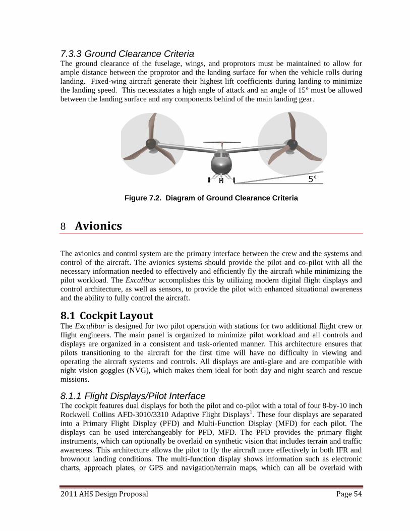
2011 AHS Design Proposal Page 54
7.3.3 Ground Clearance Criteria The ground clearance of the fuselage, wings, and proprotors must be maintained to allow for
ample distance between the proprotor and the landing surface for when the vehicle rolls during
landing. Fixed-wing aircraft generate their highest lift coefficients during landing to minimize
the landing speed. This necessitates a high angle of attack and an angle of 15º must be allowed
between the landing surface and any components behind of the main landing gear.
Figure 7.2. Diagram of Ground Clearance Criteria
8 Avionics
The avionics and control system are the primary interface between the crew and the systems and
control of the aircraft. The avionics systems should provide the pilot and co-pilot with all the
necessary information needed to effectively and efficiently fly the aircraft while minimizing the
pilot workload. The Excalibur accomplishes this by utilizing modern digital flight displays and
control architecture, as well as sensors, to provide the pilot with enhanced situational awareness
and the ability to fully control the aircraft.
8.1 Cockpit Layout The Excalibur is designed for two pilot operation with stations for two additional flight crew or
flight engineers. The main panel is organized to minimize pilot workload and all controls and
displays are organized in a consistent and task-oriented manner. This architecture ensures that
pilots transitioning to the aircraft for the first time will have no difficulty in viewing and
operating the aircraft systems and controls. All displays are anti-glare and are compatible with
night vision goggles (NVG), which makes them ideal for both day and night search and rescue
missions.
8.1.1 Flight Displays/Pilot Interface The cockpit features dual displays for both the pilot and co-pilot with a total of four 8-by-10 inch
Rockwell Collins AFD-3010/3310 Adaptive Flight Displays1. These four displays are separated
into a Primary Flight Display (PFD) and Multi-Function Display (MFD) for each pilot. The
displays can be used interchangeably for PFD, MFD. The PFD provides the primary flight
instruments, which can optionally be overlaid on synthetic vision that includes terrain and traffic
awareness. This architecture allows the pilot to fly the aircraft more effectively in both IFR and
brownout landing conditions. The multi-function display shows information such as electronic
charts, approach plates, or GPS and navigation/terrain maps, which can all be overlaid with
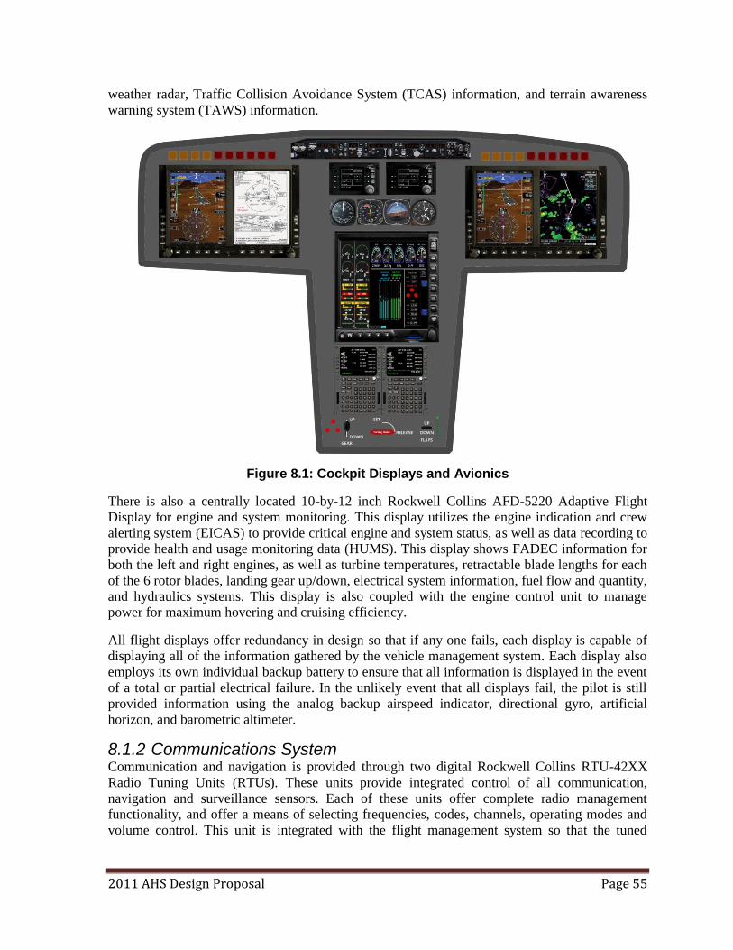
2011 AHS Design Proposal Page 55
weather radar, Traffic Collision Avoidance System (TCAS) information, and terrain awareness
warning system (TAWS) information.
Figure 8.1: Cockpit Displays and Avionics
There is also a centrally located 10-by-12 inch Rockwell Collins AFD-5220 Adaptive Flight
Display for engine and system monitoring. This display utilizes the engine indication and crew
alerting system (EICAS) to provide critical engine and system status, as well as data recording to
provide health and usage monitoring data (HUMS). This display shows FADEC information for
both the left and right engines, as well as turbine temperatures, retractable blade lengths for each
of the 6 rotor blades, landing gear up/down, electrical system information, fuel flow and quantity,
and hydraulics systems. This display is also coupled with the engine control unit to manage
power for maximum hovering and cruising efficiency.
All flight displays offer redundancy in design so that if any one fails, each display is capable of
displaying all of the information gathered by the vehicle management system. Each display also
employs its own individual backup battery to ensure that all information is displayed in the event
of a total or partial electrical failure. In the unlikely event that all displays fail, the pilot is still
provided information using the analog backup airspeed indicator, directional gyro, artificial
horizon, and barometric altimeter.
8.1.2 Communications System Communication and navigation is provided through two digital Rockwell Collins RTU-42XX
Radio Tuning Units (RTUs). These units provide integrated control of all communication,
navigation and surveillance sensors. Each of these units offer complete radio management
functionality, and offer a means of selecting frequencies, codes, channels, operating modes and
volume control. This unit is integrated with the flight management system so that the tuned
2011 AHS Design Proposal Page 56
frequency is always displayed on the RTU regardless of the tuning source. The RTU also can
display backup horizontal attitude information, and can even display backup engine display data.
The Excalibur capitalizes on the complete system integration that Rockwell Collins avionics
provide so that the pilot‘s productivity is maximized for minimal workload, while also providing
redundancy for all information provided by the vehicle management system.
In-cockpit communication is accomplished through the use of a David Clark Series 3800 Vehicle
Intercom System2. This system is capable of providing isolated communication for all crew and
passengers with an isolating U3800 master station to separate cockpit and cabin communication
at the discretion of the pilot and crew. The crews will utilize David Clark H10-76XL electronic
noise canceling headsets capable of actively cancelling ambient noise from engines, rotors, and
other vehicle systems. These headset meets MIL-26542/2 specifications for military aircraft, and
are standard in many of today‘s modern military aircraft.
8.1.3 Avionics Sensors All information presented on the flight displays originates from the vehicle management system.
This includes magnetometers, gyroscopes, accelerometers, GPS, pitot and static ports, and
FADEC information. A high-fidelity navigation system is crucial to successful mission
completion. Therefore, the Excalibur employs a Rockwell Collins Athena 611 Integrated Flight
Control System, this is a fully integrated inertial navigation system (INS), coupled with GPS, and
an air data attitude and heading reference system (ADAHRS). It works by incorporating
navigation grade IMU and altimeter data, and uses a Kalman filter to include GPS data to provide
the most accurate navigation data to the pilot. The ADAHRS also provides very accurate state
estimation data to the primary flight control computer (PFCC) to help maintain constant, safe
operation of the aircraft.
8.2 Health and Usage Monitoring Because of the large number of dynamic components on the Excalibur, including most notably
the blade retraction mechanism, rotor hub, transmission and engine systems, and nacelle tilting
mechanism, it is imperative to diagnose problems quickly and effectively. Health and Usage
Monitoring Systems (HUMS) perform much of the work for ground crews as they act as a means
of monitoring flight critical components and diagnosing potential system failures3. Life-limited
parts are monitored and automatically tracked by cycles or hours. When a part approaches its life
limit, the HUMS automatically informs the pilots or ground crew that the part has exceeded its
life expectancy. The suite of warning sensors is coupled with software that has knowledge of the
physical and temporal limits of the mechanical components to allow for a comprehensive life-
cycle analysis to be conducted in real-time. The HUMS can, therefore, monitor various aircraft
systems and warn crews of not only when a system fails but when a system might fail. The
HUMS continually monitors and compares sensor data to its database of potential risks and
failure modes that are compiled during the flight testing and certification phase. If the observed
sensor data exhibits characteristics similar to data matching a pre-existing template for failure,
the system alerts flight crews and creates a diagnostic report to be examined later by maintenance
technicians. The capabilities of the HUMS include three main functions; health monitoring,
usage monitoring, and maintenance interface.
8.2.1 Health Monitoring The health monitoring function has four main tasks which ensure all systems are operating at
their nominal performance levels. This includes a rotor track and balance, engine performance
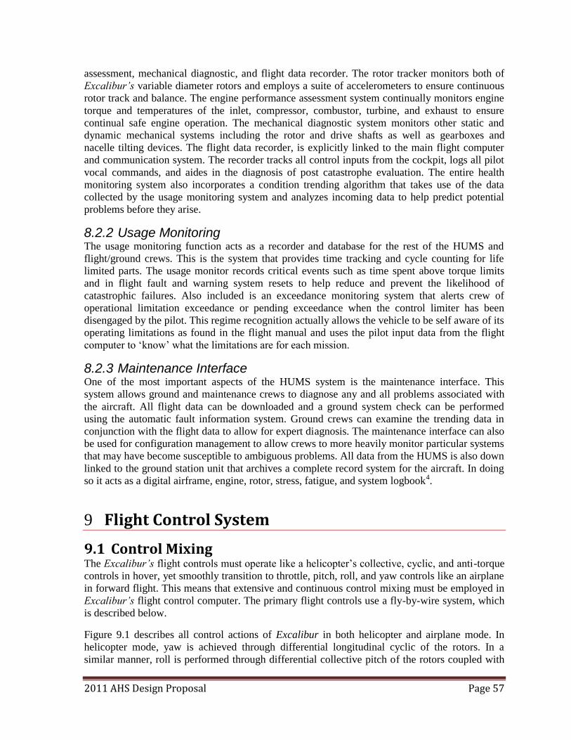
2011 AHS Design Proposal Page 57
assessment, mechanical diagnostic, and flight data recorder. The rotor tracker monitors both of
Excalibur’s variable diameter rotors and employs a suite of accelerometers to ensure continuous
rotor track and balance. The engine performance assessment system continually monitors engine
torque and temperatures of the inlet, compressor, combustor, turbine, and exhaust to ensure
continual safe engine operation. The mechanical diagnostic system monitors other static and
dynamic mechanical systems including the rotor and drive shafts as well as gearboxes and
nacelle tilting devices. The flight data recorder, is explicitly linked to the main flight computer
and communication system. The recorder tracks all control inputs from the cockpit, logs all pilot
vocal commands, and aides in the diagnosis of post catastrophe evaluation. The entire health
monitoring system also incorporates a condition trending algorithm that takes use of the data
collected by the usage monitoring system and analyzes incoming data to help predict potential
problems before they arise.
8.2.2 Usage Monitoring The usage monitoring function acts as a recorder and database for the rest of the HUMS and
flight/ground crews. This is the system that provides time tracking and cycle counting for life
limited parts. The usage monitor records critical events such as time spent above torque limits
and in flight fault and warning system resets to help reduce and prevent the likelihood of
catastrophic failures. Also included is an exceedance monitoring system that alerts crew of
operational limitation exceedance or pending exceedance when the control limiter has been
disengaged by the pilot. This regime recognition actually allows the vehicle to be self aware of its
operating limitations as found in the flight manual and uses the pilot input data from the flight
computer to ‗know‘ what the limitations are for each mission.
8.2.3 Maintenance Interface One of the most important aspects of the HUMS system is the maintenance interface. This
system allows ground and maintenance crews to diagnose any and all problems associated with
the aircraft. All flight data can be downloaded and a ground system check can be performed
using the automatic fault information system. Ground crews can examine the trending data in
conjunction with the flight data to allow for expert diagnosis. The maintenance interface can also
be used for configuration management to allow crews to more heavily monitor particular systems
that may have become susceptible to ambiguous problems. All data from the HUMS is also down
linked to the ground station unit that archives a complete record system for the aircraft. In doing
so it acts as a digital airframe, engine, rotor, stress, fatigue, and system logbook4.
9 Flight Control System
9.1 Control Mixing The Excalibur’s flight controls must operate like a helicopter‘s collective, cyclic, and anti-torque
controls in hover, yet smoothly transition to throttle, pitch, roll, and yaw controls like an airplane
in forward flight. This means that extensive and continuous control mixing must be employed in
Excalibur’s flight control computer. The primary flight controls use a fly-by-wire system, which
is described below.
Figure 9.1 describes all control actions of Excalibur in both helicopter and airplane mode. In
helicopter mode, yaw is achieved through differential longitudinal cyclic of the rotors. In a
similar manner, roll is performed through differential collective pitch of the rotors coupled with
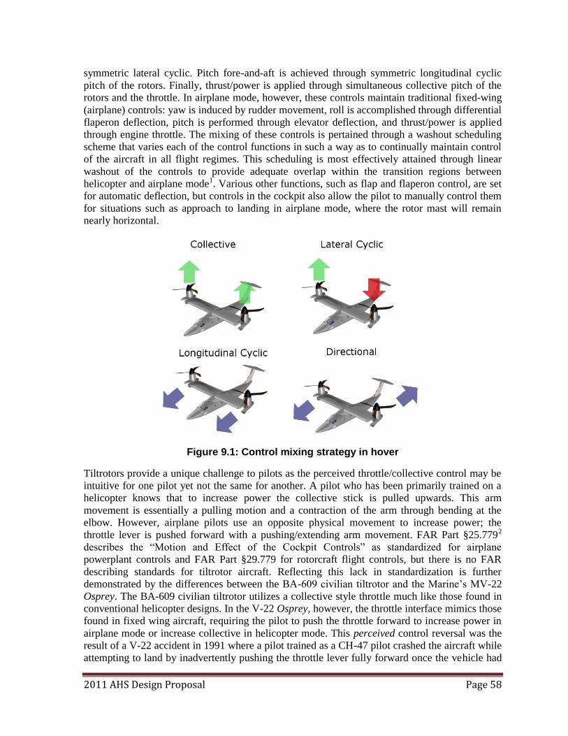
2011 AHS Design Proposal Page 58
symmetric lateral cyclic. Pitch fore-and-aft is achieved through symmetric longitudinal cyclic
pitch of the rotors. Finally, thrust/power is applied through simultaneous collective pitch of the
rotors and the throttle. In airplane mode, however, these controls maintain traditional fixed-wing
(airplane) controls: yaw is induced by rudder movement, roll is accomplished through differential
flaperon deflection, pitch is performed through elevator deflection, and thrust/power is applied
through engine throttle. The mixing of these controls is pertained through a washout scheduling
scheme that varies each of the control functions in such a way as to continually maintain control
of the aircraft in all flight regimes. This scheduling is most effectively attained through linear
washout of the controls to provide adequate overlap within the transition regions between
helicopter and airplane mode1. Various other functions, such as flap and flaperon control, are set
for automatic deflection, but controls in the cockpit also allow the pilot to manually control them
for situations such as approach to landing in airplane mode, where the rotor mast will remain
nearly horizontal.
Figure 9.1: Control mixing strategy in hover
Tiltrotors provide a unique challenge to pilots as the perceived throttle/collective control may be
intuitive for one pilot yet not the same for another. A pilot who has been primarily trained on a
helicopter knows that to increase power the collective stick is pulled upwards. This arm
movement is essentially a pulling motion and a contraction of the arm through bending at the
elbow. However, airplane pilots use an opposite physical movement to increase power; the
throttle lever is pushed forward with a pushing/extending arm movement. FAR Part §25.7792
describes the ―Motion and Effect of the Cockpit Controls‖ as standardized for airplane
powerplant controls and FAR Part §29.779 for rotorcraft flight controls, but there is no FAR
describing standards for tiltrotor aircraft. Reflecting this lack in standardization is further
demonstrated by the differences between the BA-609 civilian tiltrotor and the Marine‘s MV-22
Osprey. The BA-609 civilian tiltrotor utilizes a collective style throttle much like those found in
conventional helicopter designs. In the V-22 Osprey, however, the throttle interface mimics those
found in fixed wing aircraft, requiring the pilot to push the throttle forward to increase power in
airplane mode or increase collective in helicopter mode. This perceived control reversal was the
result of a V-22 accident in 1991 where a pilot trained as a CH-47 pilot crashed the aircraft while
attempting to land by inadvertently pushing the throttle lever fully forward once the vehicle had
2011 AHS Design Proposal Page 59
touched down3. This would have been an appropriate response in his CH-47 helicopter but it was
a pilot-caused control-reversal in the MV-22 which subsequently led to a mishap (Dugan 1998).
In high stress situations, pilots revert back to their training and this was exactly the case with the
V-22 pilot. This is a cause for problems for pilots who are not primary trained on tiltrotors.
To eliminate this issue, the Excalibur uses a novel rotational throttle interface illustrated in
Figure 9.2. This throttle interface is a two degree-of-freedom interface that transitions along with
the nacelles to provide throttle-like movement when the rotors are facing forward in airplane
mode and collective like movement when the rotors are horizontal in helicopter mode. The base
of the RTI moves via a servo control and automatically orients itself to the same angle as the
proprotor shaft. This effect is shown in Figure 9.2 below.
Figure 9.2: Rotational Throttle Interface shown in 90o helicopter and 0o fixed wing configuration (Rozovski, 2008)4
9.2 Dynamics and Stability The ability of the pilot to control the aircraft is directly affected by the complexity of the action,
by his/her training, and by any external disturbing factors. In modern military and commercial
aircraft, advances in avionics and flight controls have increased the complexity of the aircraft
and, therefore, increases the pilot‘s workload. Poor handling qualities can then make it difficult
for the pilot to maintain control over the aircraft. This affect is noted most when workloads
increase such as during a search and rescue mission, where flight operations are often in
instrument metrological conditions. During the conceptual design of an aircraft, simple linearized
models are used to predict the open-loop stability of the aircraft. These analyses do not model the
full non-linear dynamics of these vehicles and, therefore, may not be representative of the
transitional states of the aircraft between helicopter and airplane modes, but do provide insight
into steady, stick-fixed flight regimes such as hover and level, forward flight. A simplified linear
flight model was, therefore, utilized to carry out the stability and control analysis for Excalibur.
This model was developed for both helicopter mode and airplane mode through the use of a
tiltrotor trim analysis code RaPID5. The linear model was then used with each trim point as
defined by the equation AX=Bu. This is a classical flight mechanics equation where X is the state
vector and u is the control input vector. The matrices A and B correspond to the stability
derivative matrix and control derivative matrix respectively.
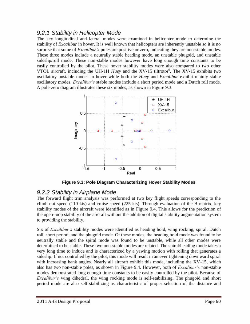
2011 AHS Design Proposal Page 60
9.2.1 Stability in Helicopter Mode The key longitudinal and lateral modes were examined in helicopter mode to determine the
stability of Excalibur in hover. It is well known that helicopters are inherently unstable so it is no
surprise that some of Excalibur’s poles are positive or zero, indicating they are non-stable modes.
These three modes include a neutrally stable heading mode, an unstable phugoid, and unstable
sideslip/roll mode. These non-stable modes however have long enough time constants to be
easily controlled by the pilot. These hover stability modes were also compared to two other
VTOL aircraft, including the UH-1H Huey and the XV-15 tiltrotor6. The XV-15 exhibits two
oscillatory unstable modes in hover while both the Huey and Excalibur exhibit mainly stable
oscillatory modes. Excalibur’s stable modes include a short period mode and a Dutch roll mode.
A pole-zero diagram illustrates these six modes, as shown in Figure 9.3.
Figure 9.3: Pole Diagram Characterizing Hover Stability Modes
9.2.2 Stability in Airplane Mode The forward flight trim analysis was performed at two key flight speeds corresponding to the
climb out speed (110 kts) and cruise speed (225 kts). Through evaluation of the A matrix, key
stability modes of the aircraft were identified as in Figure 9.4. This allows for the prediction of
the open-loop stability of the aircraft without the addition of digital stability augmentation system
to providing the stability.
Six of Excalibur’s stability modes were identified as heading hold, wing rocking, spiral, Dutch
roll, short period, and the phugoid mode. Of these modes, the heading hold mode was found to be
neutrally stable and the spiral mode was found to be unstable, while all other modes were
determined to be stable. These two non-stable modes are related. The spiral/heading mode takes a
very long time to induce and is characterized by a yawing motion with rolling that generates a
sideslip. If not controlled by the pilot, this mode will result in an ever tightening downward spiral
with increasing bank angles. Nearly all aircraft exhibit this mode, including the XV-15, which
also has two non-stable poles, as shown in Figure 9.4. However, both of Excalibur’s non-stable
modes demonstrated long enough time constants to be easily controlled by the pilot. Because of
Excalibur’s wing dihedral, the wing rocking mode is self-stabilizing. The phugoid and short
period mode are also self-stabilizing as characteristic of proper selection of the distance and
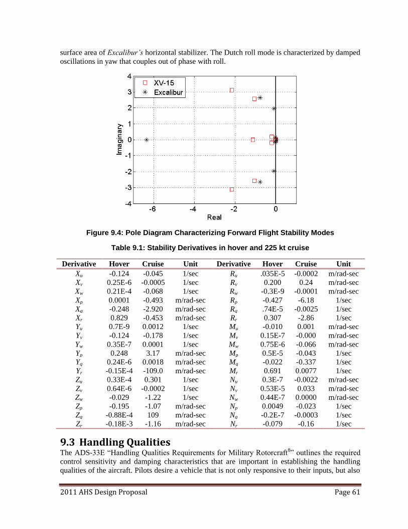
2011 AHS Design Proposal Page 61
surface area of Excalibur’s horizontal stabilizer. The Dutch roll mode is characterized by damped
oscillations in yaw that couples out of phase with roll.
Figure 9.4: Pole Diagram Characterizing Forward Flight Stability Modes
Table 9.1: Stability Derivatives in hover and 225 kt cruise
Derivative Hover Cruise Unit Derivative Hover Cruise Unit
Xu -0.124 -0.045 1/sec Ru .035E-5 -0.0002 m/rad-sec
Xv 0.25E-6 -0.0005 1/sec Rv 0.200 0.24 m/rad-sec
Xw 0.21E-4 -0.068 1/sec Rw -0.3E-9 -0.0001 m/rad-sec
Xp 0.0001 -0.493 m/rad-sec Rp -0.427 -6.18 1/sec
Xq -0.248 -2.920 m/rad-sec Rq .74E-5 -0.0025 1/sec
Xr 0.829 -0.453 m/rad-sec Rr 0.307 -2.86 1/sec
Yu 0.7E-9 0.0012 1/sec Mu -0.010 0.001 m/rad-sec
Yv -0.124 -0.178 1/sec Mv 0.15E-7 -0.000 m/rad-sec
Yw 0.35E-7 0.0001 1/sec Mw 0.75E-6 -0.066 m/rad-sec
Yp 0.248 3.17 m/rad-sec Mp 0.5E-5 -0.043 1/sec
Yq 0.24E-6 0.0018 m/rad-sec Mq -0.022 -0.337 1/sec
Yr -0.15E-4 -109.0 m/rad-sec Mr 0.691 0.0077 1/sec
Zu 0.33E-4 0.301 1/sec Nu 0.3E-7 -0.0022 m/rad-sec
Zv 0.64E-6 -0.0002 1/sec Nv 0.53E-5 0.033 m/rad-sec
Zw -0.029 -1.22 1/sec Nw 0.44E-7 0.0000 m/rad-sec
Zp -0.195 -1.07 m/rad-sec Np 0.0049 -0.023 1/sec
Zq -0.88E-4 109 m/rad-sec Nq -0.2E-7 -0.0003 1/sec
Zr -0.18E-3 -1.16 m/rad-sec Nr -0.079 -0.16 1/sec
9.3 Handling Qualities The ADS-33E ―Handling Qualities Requirements for Military Rotorcraft8‖ outlines the required
control sensitivity and damping characteristics that are important in establishing the handling
qualities of the aircraft. Pilots desire a vehicle that is not only responsive to their inputs, but also
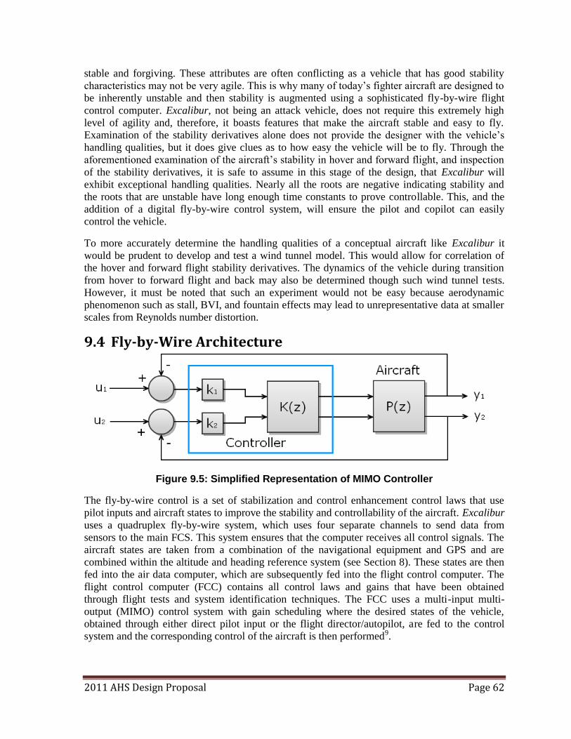
2011 AHS Design Proposal Page 62
stable and forgiving. These attributes are often conflicting as a vehicle that has good stability
characteristics may not be very agile. This is why many of today‘s fighter aircraft are designed to
be inherently unstable and then stability is augmented using a sophisticated fly-by-wire flight
control computer. Excalibur, not being an attack vehicle, does not require this extremely high
level of agility and, therefore, it boasts features that make the aircraft stable and easy to fly.
Examination of the stability derivatives alone does not provide the designer with the vehicle‘s
handling qualities, but it does give clues as to how easy the vehicle will be to fly. Through the
aforementioned examination of the aircraft‘s stability in hover and forward flight, and inspection
of the stability derivatives, it is safe to assume in this stage of the design, that Excalibur will
exhibit exceptional handling qualities. Nearly all the roots are negative indicating stability and
the roots that are unstable have long enough time constants to prove controllable. This, and the
addition of a digital fly-by-wire control system, will ensure the pilot and copilot can easily
control the vehicle.
To more accurately determine the handling qualities of a conceptual aircraft like Excalibur it
would be prudent to develop and test a wind tunnel model. This would allow for correlation of
the hover and forward flight stability derivatives. The dynamics of the vehicle during transition
from hover to forward flight and back may also be determined though such wind tunnel tests.
However, it must be noted that such an experiment would not be easy because aerodynamic
phenomenon such as stall, BVI, and fountain effects may lead to unrepresentative data at smaller
scales from Reynolds number distortion.
9.4 Fly-by-Wire Architecture
Figure 9.5: Simplified Representation of MIMO Controller
The fly-by-wire control is a set of stabilization and control enhancement control laws that use
pilot inputs and aircraft states to improve the stability and controllability of the aircraft. Excalibur
uses a quadruplex fly-by-wire system, which uses four separate channels to send data from
sensors to the main FCS. This system ensures that the computer receives all control signals. The
aircraft states are taken from a combination of the navigational equipment and GPS and are
combined within the altitude and heading reference system (see Section 8). These states are then
fed into the air data computer, which are subsequently fed into the flight control computer. The
flight control computer (FCC) contains all control laws and gains that have been obtained
through flight tests and system identification techniques. The FCC uses a multi-input multi-
output (MIMO) control system with gain scheduling where the desired states of the vehicle,
obtained through either direct pilot input or the flight director/autopilot, are fed to the control
system and the corresponding control of the aircraft is then performed9.
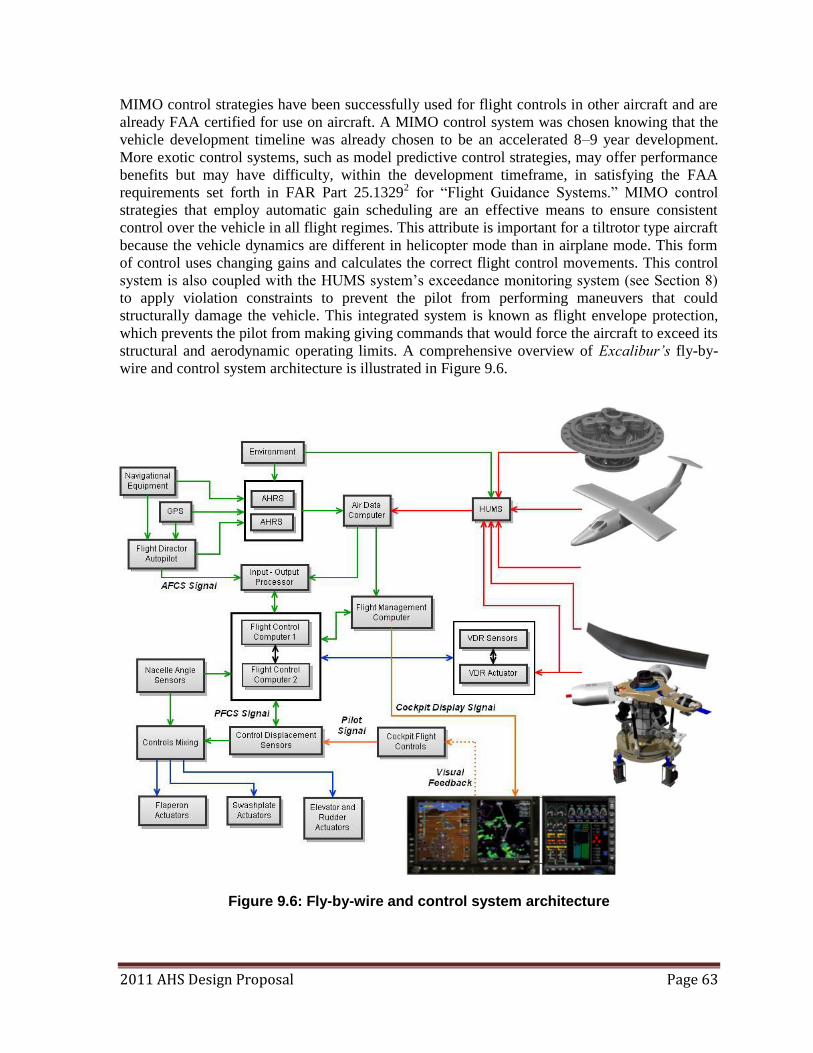
2011 AHS Design Proposal Page 63
MIMO control strategies have been successfully used for flight controls in other aircraft and are
already FAA certified for use on aircraft. A MIMO control system was chosen knowing that the
vehicle development timeline was already chosen to be an accelerated 8–9 year development.
More exotic control systems, such as model predictive control strategies, may offer performance
benefits but may have difficulty, within the development timeframe, in satisfying the FAA
requirements set forth in FAR Part 25.13292 for ―Flight Guidance Systems.‖ MIMO control
strategies that employ automatic gain scheduling are an effective means to ensure consistent
control over the vehicle in all flight regimes. This attribute is important for a tiltrotor type aircraft
because the vehicle dynamics are different in helicopter mode than in airplane mode. This form
of control uses changing gains and calculates the correct flight control movements. This control
system is also coupled with the HUMS system‘s exceedance monitoring system (see Section 8)
to apply violation constraints to prevent the pilot from performing maneuvers that could
structurally damage the vehicle. This integrated system is known as flight envelope protection,
which prevents the pilot from making giving commands that would force the aircraft to exceed its
structural and aerodynamic operating limits. A comprehensive overview of Excalibur’s fly-by-
wire and control system architecture is illustrated in Figure 9.6.
Figure 9.6: Fly-by-wire and control system architecture
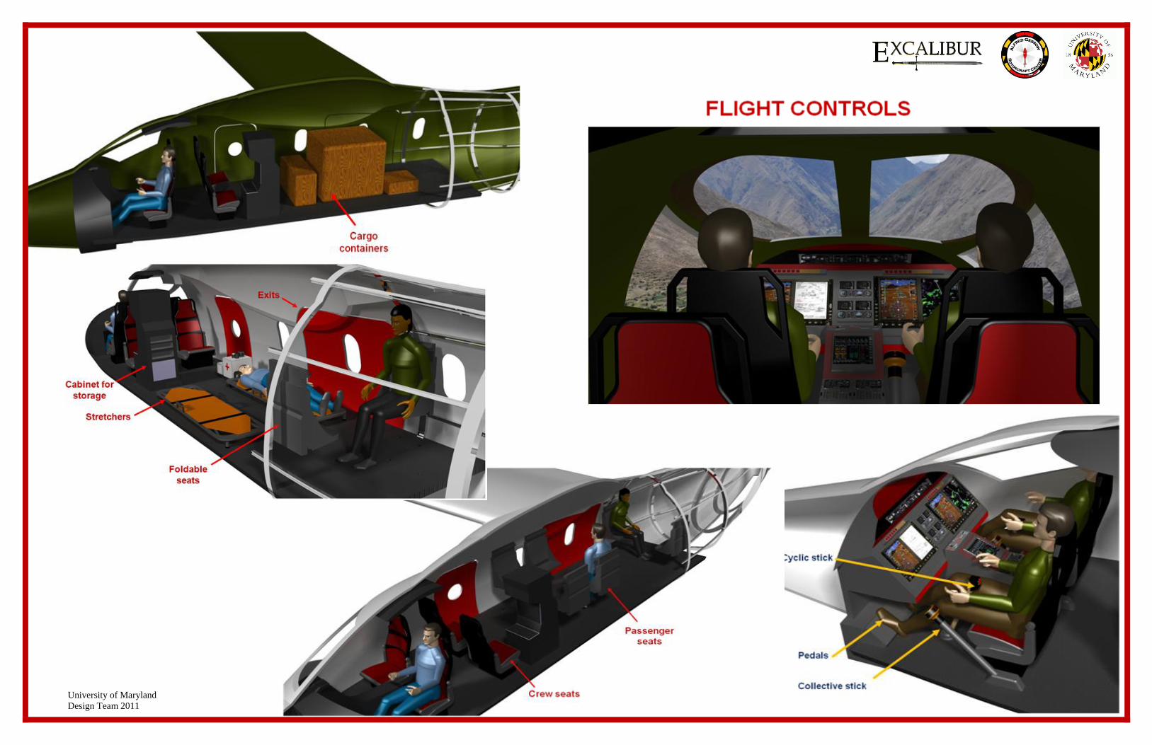
University of Maryland
Design Team 2011
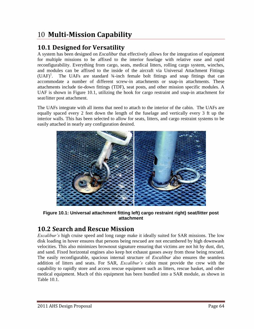
2011 AHS Design Proposal Page 64
10 Multi-Mission Capability
10.1 Designed for Versatility A system has been designed on Excalibur that effectively allows for the integration of equipment
for multiple missions to be affixed to the interior fuselage with relative ease and rapid
reconfigurability. Everything from cargo, seats, medical litters, rolling cargo system, winches,
and modules can be affixed to the inside of the aircraft via Universal Attachment Fittings
(UAF)1. The UAFs are standard ¾-inch female bolt fittings and snap fittings that can
accommodate a number of different screw-in attachments or snap-in attachments. These
attachments include tie-down fittings (TDF), seat posts, and other mission specific modules. A
UAF is shown in Figure 10.1, utilizing the hook for cargo restraint and snap-in attachment for
seat/litter post attachment.
The UAFs integrate with all items that need to attach to the interior of the cabin. The UAFs are
equally spaced every 2 feet down the length of the fuselage and vertically every 3 ft up the
interior walls. This has been selected to allow for seats, litters, and cargo restraint systems to be
easily attached in nearly any configuration desired.
Figure 10.1: Universal attachment fitting left) cargo restraint right) seat/litter post attachment
10.2 Search and Rescue Mission Excalibur’s high cruise speed and long range make it ideally suited for SAR missions. The low
disk loading in hover ensures that persons being rescued are not encumbered by high downwash
velocities. This also minimizes brownout signature ensuring that victims are not hit by dust, dirt,
and sand. Fixed horizontal engines also keep hot exhaust gasses away from those being rescued.
The easily reconfigurable, spacious internal structure of Excalibur also ensures the seamless
addition of litters and seats. For SAR, Excalibur’s cabin must provide the crew with the
capability to rapidly store and access rescue equipment such as litters, rescue basket, and other
medical equipment. Much of this equipment has been bundled into a SAR module, as shown in
Table 10.1.
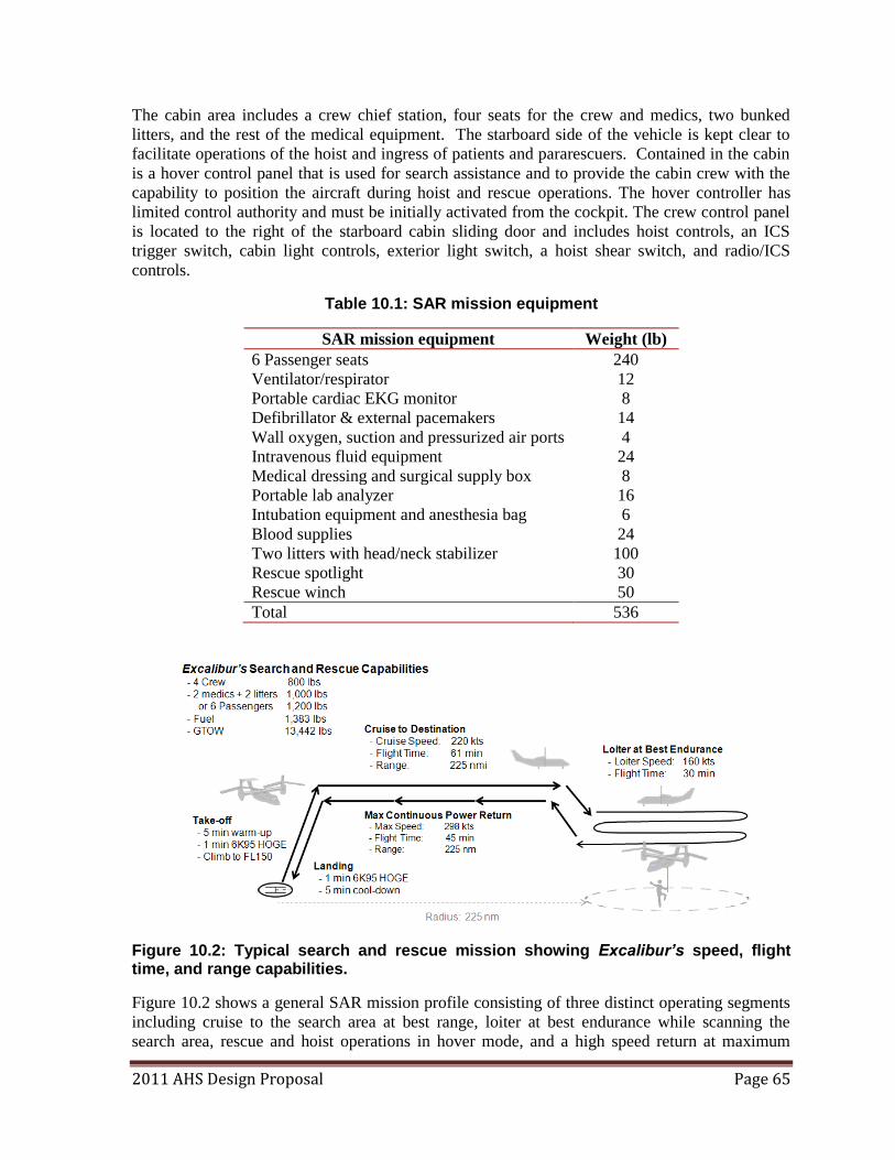
2011 AHS Design Proposal Page 65
The cabin area includes a crew chief station, four seats for the crew and medics, two bunked
litters, and the rest of the medical equipment. The starboard side of the vehicle is kept clear to
facilitate operations of the hoist and ingress of patients and pararescuers. Contained in the cabin
is a hover control panel that is used for search assistance and to provide the cabin crew with the
capability to position the aircraft during hoist and rescue operations. The hover controller has
limited control authority and must be initially activated from the cockpit. The crew control panel
is located to the right of the starboard cabin sliding door and includes hoist controls, an ICS
trigger switch, cabin light controls, exterior light switch, a hoist shear switch, and radio/ICS
controls.
Table 10.1: SAR mission equipment
SAR mission equipment Weight (lb)
6 Passenger seats 240
Ventilator/respirator 12
Portable cardiac EKG monitor 8
Defibrillator & external pacemakers 14
Wall oxygen, suction and pressurized air ports 4
Intravenous fluid equipment 24
Medical dressing and surgical supply box 8
Portable lab analyzer 16
Intubation equipment and anesthesia bag 6
Blood supplies 24
Two litters with head/neck stabilizer 100
Rescue spotlight 30
Rescue winch 50
Total 536
Figure 10.2: Typical search and rescue mission showing Excalibur’s speed, flight time, and range capabilities.
Figure 10.2 shows a general SAR mission profile consisting of three distinct operating segments
including cruise to the search area at best range, loiter at best endurance while scanning the
search area, rescue and hoist operations in hover mode, and a high speed return at maximum
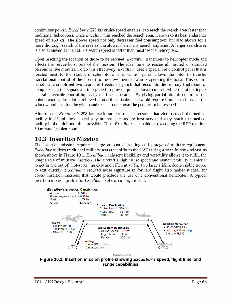
2011 AHS Design Proposal Page 66
continuous power. Excalibur’s 220 kts cruise speed enables it to reach the search area faster than
traditional helicopters. Once Excalibur has reached the search area, it slows to its best endurance
speed of 160 kts. The slower speed not only decreases fuel consumption, but also allows for a
more thorough search of the area as it is slower than many search airplanes. A larger search area
is also achieved as the 160 kts search speed is faster than most rescue helicopters.
Upon reaching the location of those to be rescued, Excalibur transitions to helicopter mode and
effects the rescue/hoist part of the mission. The ideal time to rescue all injured or stranded
persons is five minutes. To do this effectively, Excalibur uses a special crew control panel that is
located next to the starboard cabin door. This control panel allows the pilot to transfer
translational control of the aircraft to the crew member who is operating the hoist. This control
panel has a simplified two degree of freedom joystick that feeds into the primary flight control
computer and the signals are interpreted to provide precise hover control, while the pilots inputs
can still override control inputs by the hoist operator. By giving partial aircraft control to the
hoist operator, the pilot is relieved of additional tasks that would require him/her to look out the
window and position the winch and rescue basket near the persons to be rescued.
After rescue, Excalibur’s 298 kts maximum cruise speed ensures that victims reach the medical
facility in 45 minutes as critically injured persons are best served if they reach the medical
facility in the minimum time possible. Thus, Excalibur is capable of exceeding the RFP required
50 minute ―golden hour.‖
10.3 Insertion Mission The insertion mission requires a large amount of seating and storage of military equipment.
Excalibur utilizes traditional military seats that affix to the UAFs using a snap-in hook release as
shown above in Figure 10.1. Excalibur’s inherent flexibility and versatility allows it to fulfill the
unique role of military insertion. The aircraft‘s high cruise speed and maneuverability enables it
to get in and out of ―hot-spots‖ quickly and efficiently. The two large sliding doors enable troops
to exit quickly. Excalibur’s reduced noise signature in forward flight also makes it ideal for
covert insertion missions that would preclude the use of a conventional helicopter. A typical
insertion mission profile for Excalibur is shown in Figure 10.3.
Figure 10.3: Insertion mission profile showing Excalibur’s speed, flight time, and
range capabilities
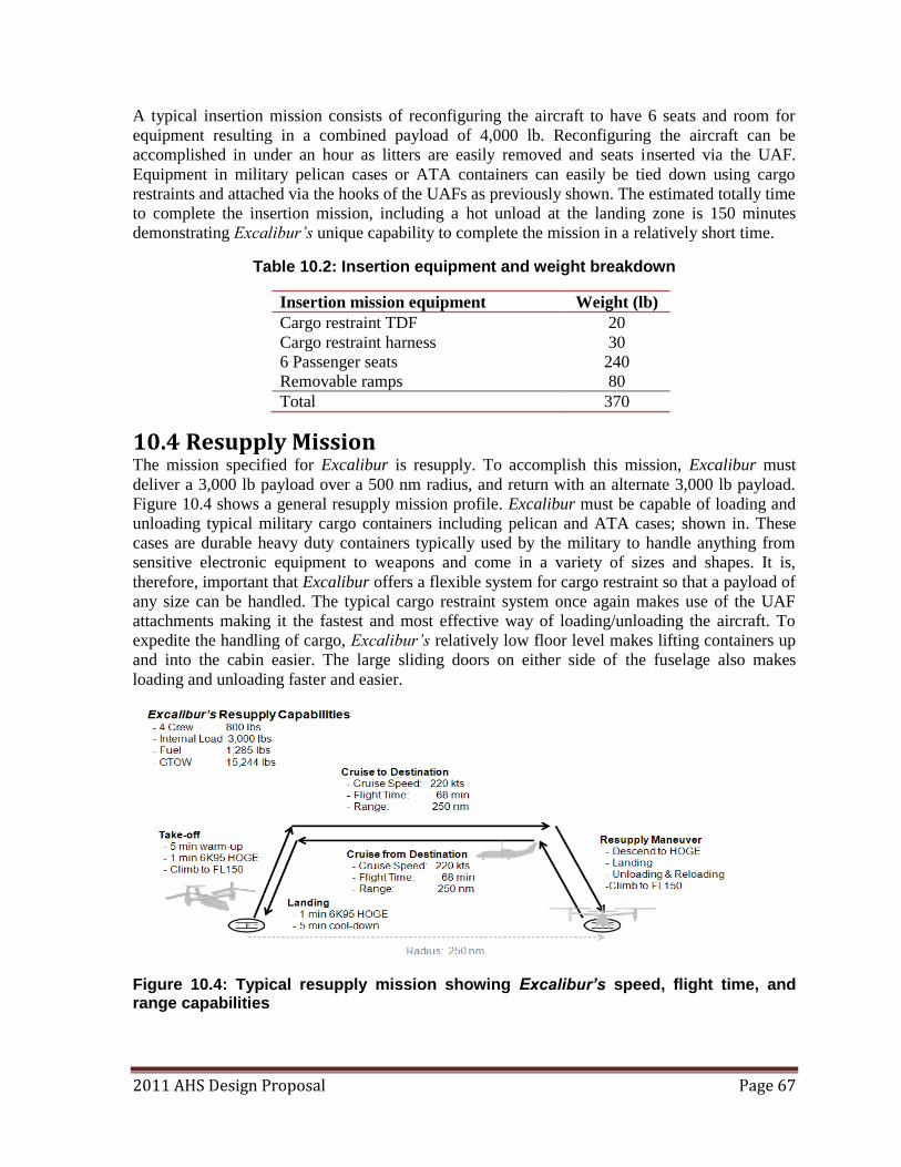
2011 AHS Design Proposal Page 67
A typical insertion mission consists of reconfiguring the aircraft to have 6 seats and room for
equipment resulting in a combined payload of 4,000 lb. Reconfiguring the aircraft can be
accomplished in under an hour as litters are easily removed and seats inserted via the UAF.
Equipment in military pelican cases or ATA containers can easily be tied down using cargo
restraints and attached via the hooks of the UAFs as previously shown. The estimated totally time
to complete the insertion mission, including a hot unload at the landing zone is 150 minutes
demonstrating Excalibur’s unique capability to complete the mission in a relatively short time.
Table 10.2: Insertion equipment and weight breakdown
Insertion mission equipment Weight (lb)
Cargo restraint TDF 20
Cargo restraint harness 30
6 Passenger seats 240
Removable ramps 80
Total 370
10.4 Resupply Mission The mission specified for Excalibur is resupply. To accomplish this mission, Excalibur must
deliver a 3,000 lb payload over a 500 nm radius, and return with an alternate 3,000 lb payload.
Figure 10.4 shows a general resupply mission profile. Excalibur must be capable of loading and
unloading typical military cargo containers including pelican and ATA cases; shown in. These
cases are durable heavy duty containers typically used by the military to handle anything from
sensitive electronic equipment to weapons and come in a variety of sizes and shapes. It is,
therefore, important that Excalibur offers a flexible system for cargo restraint so that a payload of
any size can be handled. The typical cargo restraint system once again makes use of the UAF
attachments making it the fastest and most effective way of loading/unloading the aircraft. To
expedite the handling of cargo, Excalibur’s relatively low floor level makes lifting containers up
and into the cabin easier. The large sliding doors on either side of the fuselage also makes
loading and unloading faster and easier.
Figure 10.4: Typical resupply mission showing Excalibur’s speed, flight time, and range capabilities
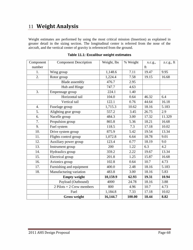
2011 AHS Design Proposal Page 68
11 Weight Analysis
Weight estimates are performed by using the most critical mission (Insertion) as explained in
greater detail in the sizing section. The longitudinal center is referred from the nose of the
aircraft, and the vertical center of gravity is referenced from the ground.
Table 11.1: Excalibur weight estimates
Component
number
Component Description Weight, lbs % Weight x.c.g.,
ft
z.c.g., ft
1. Wing group 1,148.6 7.11 19.47 9.95
2. Rotor group 1,224.4 7.58 19.15 16.68
Blade assembly 476.7 2.95
Hub and Hinge 747.7 4.63
3. Empennage group 224.1 1.40
Horizontal tail 104.0 0.64 46.32 6.4
Vertical tail 122.1 0.76 44.64 16.18
4. Fuselage group 1,715.3 10.62 18.16 5.183
5. Alighting gear group 557.2 3.45 26.75 2.9
6. Nacelle group 484.3 3.00 17.32 11.329
7. Propulsion group 865.8 5.36 18.21 16.68
9. Fuel system 118.5 7.3 17.18 10.02
10. Drive system group 875.9 5.42 19.54 13.34
11. Flights control group 1,072.8 6.64 18.78 9.01
12. Auxiliary power group 123.4 0.77 18.19 9.0
13. Instrument group 200 1.22 6.3 4.2
14. Hydraulics group 359.2 2.22 19.67 13.34
15. Electrical group 201.8 1.25 15.87 16.68
16. Avionics group 102.8 0.64 10.7 4.73
17. Furnishing and equipment 400.0 2.48 18.16 5.183
18. Manufacturing variation 483.8 3.00 18.16 5.83
Empty weight 10,159.9 62.93 19.31 10.94
Payload (Outbound) 4000 24.78 18.16 3.88
2 Pilots + 2 Crew members 800 4.96 10.7 4.73
Fuel 1,184.8 7.33 17.18 10.02
Gross weight 16,144.7 100.00 18.44 8.82
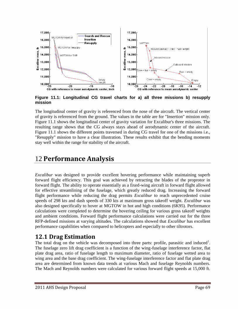
2011 AHS Design Proposal Page 69
Figure 11.1: Longitudinal CG travel charts for a) all three missions b) resupply mission
The longitudinal center of gravity is referenced from the nose of the aircraft. The vertical center
of gravity is referenced from the ground. The values in the table are for "Insertion" mission only.
Figure 11.1 shows the longitudinal center of gravity variation for Excalibur's three missions. The
resulting range shows that the CG always stays ahead of aerodynamic center of the aircraft.
Figure 11.1 shows the different points traversed in during CG travel for one of the missions i.e.,
"Resupply" mission to have a clear illustration. These results exhibit that the bending moments
stay well within the range for stability of the aircraft.
12 Performance Analysis
Excalibur was designed to provide excellent hovering performance while maintaining superb
forward flight efficiency. This goal was achieved by retracting the blades of the proprotor in
forward flight. The ability to operate essentially as a fixed-wing aircraft in forward flight allowed
for effective streamlining of the fuselage, which greatly reduced drag. Increasing the forward
flight performance while reducing the drag permits Excalibur to reach unprecedented cruise
speeds of 298 kts and dash speeds of 330 kts at maximum gross takeoff weight. Excalibur was
also designed specifically to hover at MGTOW in hot and high conditions (6K95). Performance
calculations were completed to determine the hovering ceiling for various gross takeoff weights
and ambient conditions. Forward flight performance calculations were carried out for the three
RFP-defined missions at varying altitudes. The calculations showed that Excalibur has excellent
performance capabilities when compared to helicopters and especially to other tiltrotors.
12.1 Drag Estimation The total drag on the vehicle was decomposed into three parts: profile, parasitic and induced1.
The fuselage zero lift drag coefficient is a function of the wing-fuselage interference factor, flat
plate drag area, ratio of fuselage length to maximum diameter, ratio of fuselage wetted area to
wing area and the base drag coefficient. The wing-fuselage interference factor and flat plate drag
area are determined from known data trends at various Mach and fuselage Reynolds numbers.
The Mach and Reynolds numbers were calculated for various forward flight speeds at 15,000 ft.
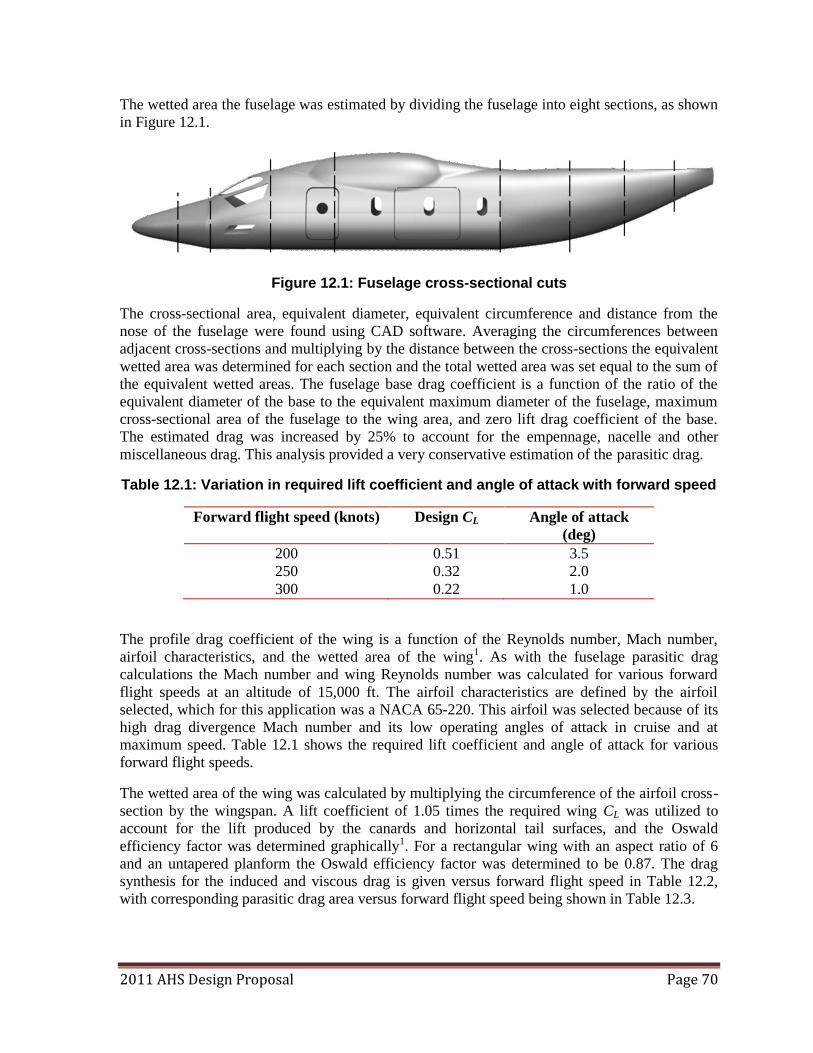
2011 AHS Design Proposal Page 70
The wetted area the fuselage was estimated by dividing the fuselage into eight sections, as shown
in Figure 12.1.
Figure 12.1: Fuselage cross-sectional cuts
The cross-sectional area, equivalent diameter, equivalent circumference and distance from the
nose of the fuselage were found using CAD software. Averaging the circumferences between
adjacent cross-sections and multiplying by the distance between the cross-sections the equivalent
wetted area was determined for each section and the total wetted area was set equal to the sum of
the equivalent wetted areas. The fuselage base drag coefficient is a function of the ratio of the
equivalent diameter of the base to the equivalent maximum diameter of the fuselage, maximum
cross-sectional area of the fuselage to the wing area, and zero lift drag coefficient of the base.
The estimated drag was increased by 25% to account for the empennage, nacelle and other
miscellaneous drag. This analysis provided a very conservative estimation of the parasitic drag.
Table 12.1: Variation in required lift coefficient and angle of attack with forward speed
Forward flight speed (knots) Design CL Angle of attack
(deg)
200 0.51 3.5
250 0.32 2.0
300 0.22 1.0
The profile drag coefficient of the wing is a function of the Reynolds number, Mach number,
airfoil characteristics, and the wetted area of the wing1. As with the fuselage parasitic drag
calculations the Mach number and wing Reynolds number was calculated for various forward
flight speeds at an altitude of 15,000 ft. The airfoil characteristics are defined by the airfoil
selected, which for this application was a NACA 65-220. This airfoil was selected because of its
high drag divergence Mach number and its low operating angles of attack in cruise and at
maximum speed. Table 12.1 shows the required lift coefficient and angle of attack for various
forward flight speeds.
The wetted area of the wing was calculated by multiplying the circumference of the airfoil cross-
section by the wingspan. A lift coefficient of 1.05 times the required wing CL was utilized to
account for the lift produced by the canards and horizontal tail surfaces, and the Oswald
efficiency factor was determined graphically1. For a rectangular wing with an aspect ratio of 6
and an untapered planform the Oswald efficiency factor was determined to be 0.87. The drag
synthesis for the induced and viscous drag is given versus forward flight speed in Table 12.2,
with corresponding parasitic drag area versus forward flight speed being shown in Table 12.3.
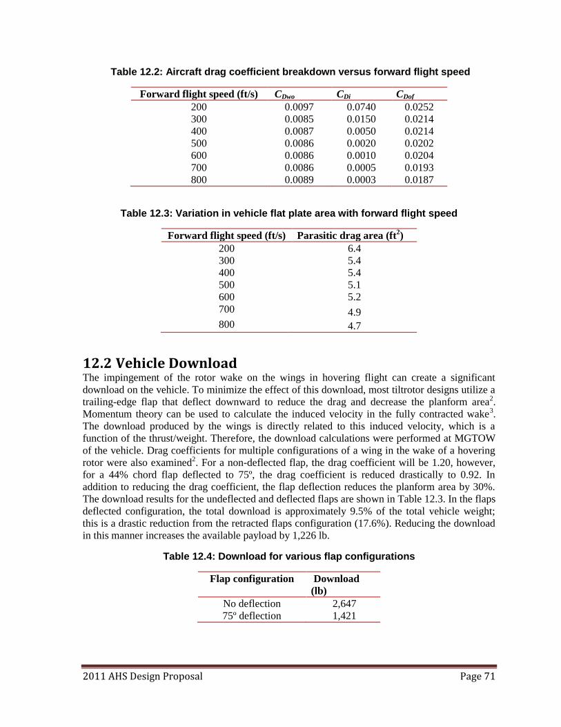
2011 AHS Design Proposal Page 71
Table 12.2: Aircraft drag coefficient breakdown versus forward flight speed
Forward flight speed (ft/s) CDwo CDi CDof
200 0.0097 0.0740 0.0252
300 0.0085 0.0150 0.0214
400 0.0087 0.0050 0.0214
500 0.0086 0.0020 0.0202
600 0.0086 0.0010 0.0204
700 0.0086 0.0005 0.0193
800 0.0089 0.0003 0.0187
Table 12.3: Variation in vehicle flat plate area with forward flight speed
Forward flight speed (ft/s) Parasitic drag area (ft2)
200 6.4
300 5.4
400 5.4
500 5.1
600 5.2
700 4.9
800 4.7
12.2 Vehicle Download The impingement of the rotor wake on the wings in hovering flight can create a significant
download on the vehicle. To minimize the effect of this download, most tiltrotor designs utilize a
trailing-edge flap that deflect downward to reduce the drag and decrease the planform area2.
Momentum theory can be used to calculate the induced velocity in the fully contracted wake3.
The download produced by the wings is directly related to this induced velocity, which is a
function of the thrust/weight. Therefore, the download calculations were performed at MGTOW
of the vehicle. Drag coefficients for multiple configurations of a wing in the wake of a hovering
rotor were also examined2. For a non-deflected flap, the drag coefficient will be 1.20, however,
for a 44% chord flap deflected to 75º, the drag coefficient is reduced drastically to 0.92. In
addition to reducing the drag coefficient, the flap deflection reduces the planform area by 30%.
The download results for the undeflected and deflected flaps are shown in Table 12.3. In the flaps
deflected configuration, the total download is approximately 9.5% of the total vehicle weight;
this is a drastic reduction from the retracted flaps configuration (17.6%). Reducing the download
in this manner increases the available payload by 1,226 lb.
Table 12.4: Download for various flap configurations
Flap configuration Download
(lb)
No deflection 2,647
75º deflection 1,421
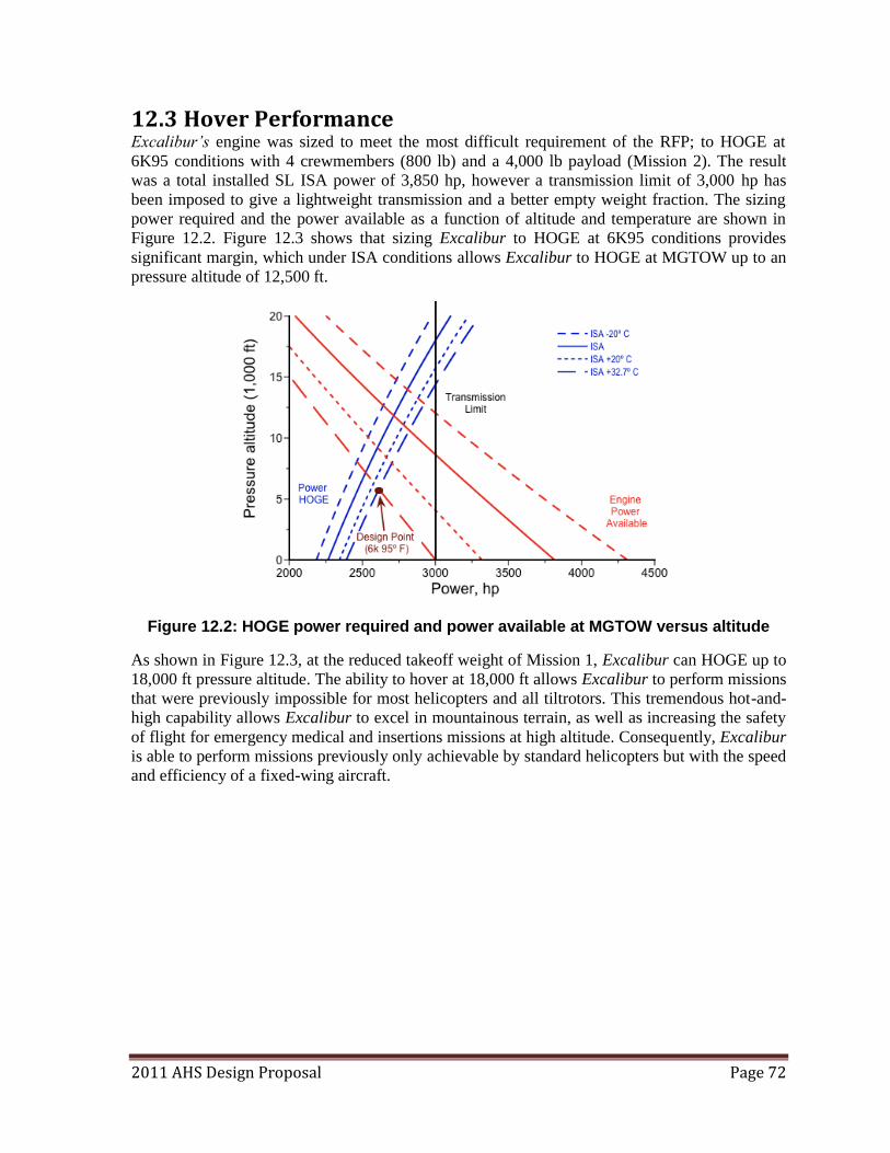
2011 AHS Design Proposal Page 72
12.3 Hover Performance Excalibur’s engine was sized to meet the most difficult requirement of the RFP; to HOGE at
6K95 conditions with 4 crewmembers (800 lb) and a 4,000 lb payload (Mission 2). The result
was a total installed SL ISA power of 3,850 hp, however a transmission limit of 3,000 hp has
been imposed to give a lightweight transmission and a better empty weight fraction. The sizing
power required and the power available as a function of altitude and temperature are shown in
Figure 12.2. Figure 12.3 shows that sizing Excalibur to HOGE at 6K95 conditions provides
significant margin, which under ISA conditions allows Excalibur to HOGE at MGTOW up to an
pressure altitude of 12,500 ft.
Figure 12.2: HOGE power required and power available at MGTOW versus altitude
As shown in Figure 12.3, at the reduced takeoff weight of Mission 1, Excalibur can HOGE up to
18,000 ft pressure altitude. The ability to hover at 18,000 ft allows Excalibur to perform missions
that were previously impossible for most helicopters and all tiltrotors. This tremendous hot-and-
high capability allows Excalibur to excel in mountainous terrain, as well as increasing the safety
of flight for emergency medical and insertions missions at high altitude. Consequently, Excalibur
is able to perform missions previously only achievable by standard helicopters but with the speed
and efficiency of a fixed-wing aircraft.
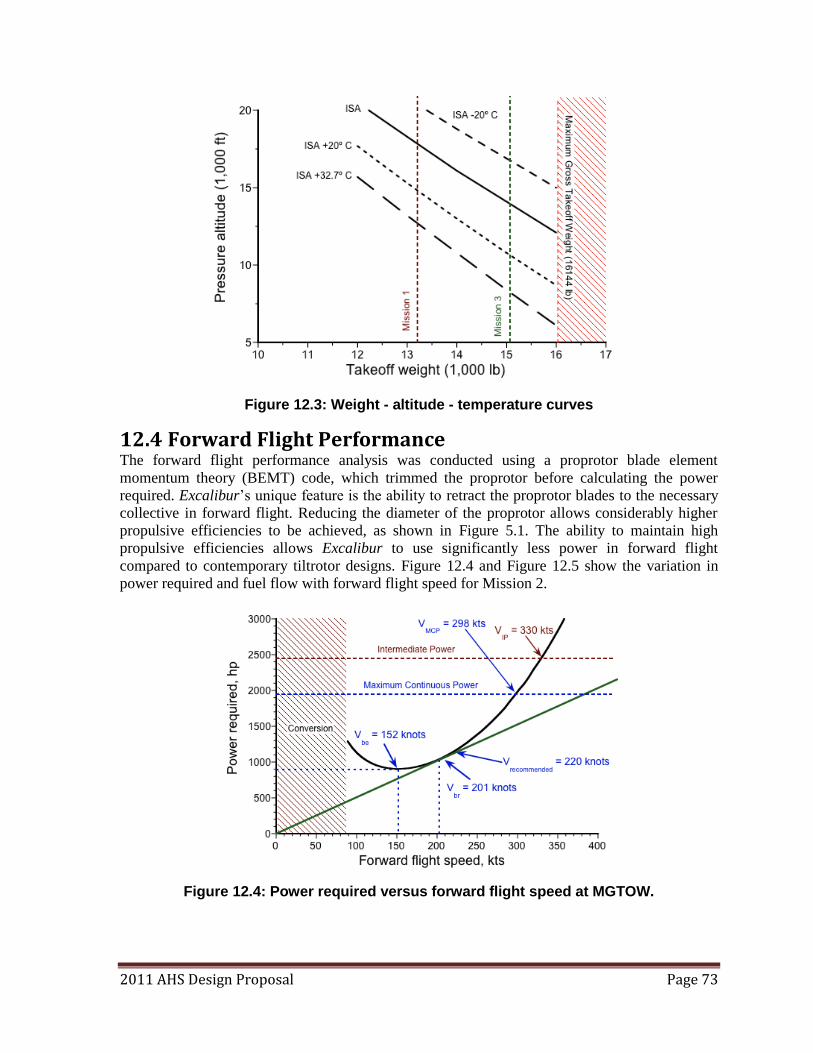
2011 AHS Design Proposal Page 73
Figure 12.3: Weight - altitude - temperature curves
12.4 Forward Flight Performance The forward flight performance analysis was conducted using a proprotor blade element
momentum theory (BEMT) code, which trimmed the proprotor before calculating the power
required. Excalibur‘s unique feature is the ability to retract the proprotor blades to the necessary
collective in forward flight. Reducing the diameter of the proprotor allows considerably higher
propulsive efficiencies to be achieved, as shown in Figure 5.1. The ability to maintain high
propulsive efficiencies allows Excalibur to use significantly less power in forward flight
compared to contemporary tiltrotor designs. Figure 12.4 and Figure 12.5 show the variation in
power required and fuel flow with forward flight speed for Mission 2.
Figure 12.4: Power required versus forward flight speed at MGTOW.
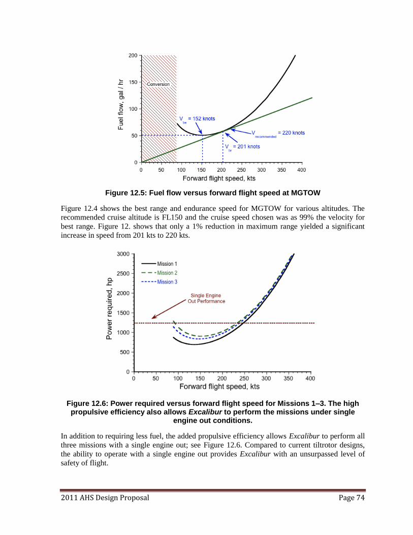
2011 AHS Design Proposal Page 74
Figure 12.5: Fuel flow versus forward flight speed at MGTOW
Figure 12.4 shows the best range and endurance speed for MGTOW for various altitudes. The
recommended cruise altitude is FL150 and the cruise speed chosen was as 99% the velocity for
best range. Figure 12. shows that only a 1% reduction in maximum range yielded a significant
increase in speed from 201 kts to 220 kts.
Figure 12.6: Power required versus forward flight speed for Missions 1–3. The high propulsive efficiency also allows Excalibur to perform the missions under single
engine out conditions.
In addition to requiring less fuel, the added propulsive efficiency allows Excalibur to perform all
three missions with a single engine out; see Figure 12.6. Compared to current tiltrotor designs,
the ability to operate with a single engine out provides Excalibur with an unsurpassed level of
safety of flight.
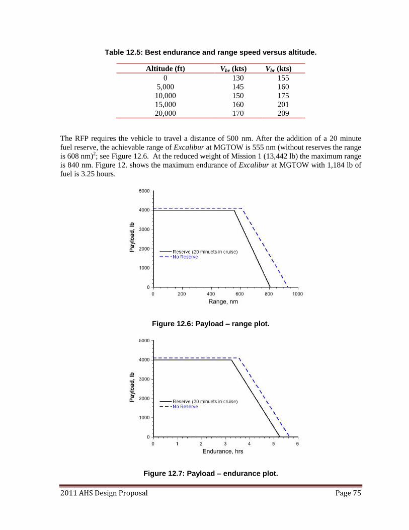
2011 AHS Design Proposal Page 75
Table 12.5: Best endurance and range speed versus altitude.
Altitude (ft) Vbe (kts) Vbr (kts)
0 130 155
5,000 145 160
10,000 150 175
15,000 160 201
20,000 170 209
The RFP requires the vehicle to travel a distance of 500 nm. After the addition of a 20 minute
fuel reserve, the achievable range of Excalibur at MGTOW is 555 nm (without reserves the range
is 608 nm)2; see Figure 12.6. At the reduced weight of Mission 1 (13,442 lb) the maximum range
is 840 nm. Figure 12. shows the maximum endurance of Excalibur at MGTOW with 1,184 lb of
fuel is 3.25 hours.
Figure 12.6: Payload – range plot.
Figure 12.7: Payload – endurance plot.
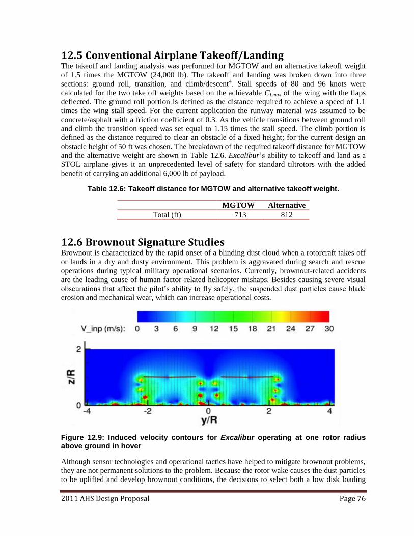
2011 AHS Design Proposal Page 76
12.5 Conventional Airplane Takeoff/Landing The takeoff and landing analysis was performed for MGTOW and an alternative takeoff weight
of 1.5 times the MGTOW (24,000 lb). The takeoff and landing was broken down into three
sections: ground roll, transition, and climb/descent4. Stall speeds of 80 and 96 knots were
calculated for the two take off weights based on the achievable CLmax of the wing with the flaps
deflected. The ground roll portion is defined as the distance required to achieve a speed of 1.1
times the wing stall speed. For the current application the runway material was assumed to be
concrete/asphalt with a friction coefficient of 0.3. As the vehicle transitions between ground roll
and climb the transition speed was set equal to 1.15 times the stall speed. The climb portion is
defined as the distance required to clear an obstacle of a fixed height; for the current design an
obstacle height of 50 ft was chosen. The breakdown of the required takeoff distance for MGTOW
and the alternative weight are shown in Table 12.6. Excalibur‘s ability to takeoff and land as a
STOL airplane gives it an unprecedented level of safety for standard tiltrotors with the added
benefit of carrying an additional 6,000 lb of payload.
Table 12.6: Takeoff distance for MGTOW and alternative takeoff weight.
MGTOW Alternative
Total (ft) 713 812
12.6 Brownout Signature Studies Brownout is characterized by the rapid onset of a blinding dust cloud when a rotorcraft takes off
or lands in a dry and dusty environment. This problem is aggravated during search and rescue
operations during typical military operational scenarios. Currently, brownout-related accidents
are the leading cause of human factor-related helicopter mishaps. Besides causing severe visual
obscurations that affect the pilot‘s ability to fly safely, the suspended dust particles cause blade
erosion and mechanical wear, which can increase operational costs.
Figure 12.9: Induced velocity contours for Excalibur operating at one rotor radius above ground in hover
Although sensor technologies and operational tactics have helped to mitigate brownout problems,
they are not permanent solutions to the problem. Because the rotor wake causes the dust particles
to be uplifted and develop brownout conditions, the decisions to select both a low disk loading
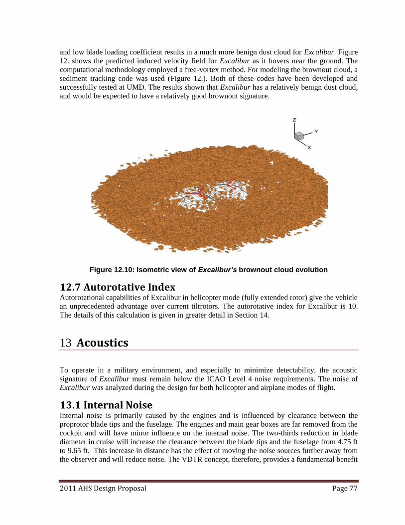
2011 AHS Design Proposal Page 77
and low blade loading coefficient results in a much more benign dust cloud for Excalibur. Figure
12. shows the predicted induced velocity field for Excalibur as it hovers near the ground. The
computational methodology employed a free-vortex method. For modeling the brownout cloud, a
sediment tracking code was used (Figure 12.). Both of these codes have been developed and
successfully tested at UMD. The results shown that Excalibur has a relatively benign dust cloud,
and would be expected to have a relatively good brownout signature.
Figure 12.10: Isometric view of Excalibur’s brownout cloud evolution
12.7 Autorotative Index Autorotational capabilities of Excalibur in helicopter mode (fully extended rotor) give the vehicle
an unprecedented advantage over current tiltrotors. The autorotative index for Excalibur is 10.
The details of this calculation is given in greater detail in Section 14.
13 Acoustics
To operate in a military environment, and especially to minimize detectability, the acoustic
signature of Excalibur must remain below the ICAO Level 4 noise requirements. The noise of
Excalibur was analyzed during the design for both helicopter and airplane modes of flight.
13.1 Internal Noise Internal noise is primarily caused by the engines and is influenced by clearance between the
proprotor blade tips and the fuselage. The engines and main gear boxes are far removed from the
cockpit and will have minor influence on the internal noise. The two-thirds reduction in blade
diameter in cruise will increase the clearance between the blade tips and the fuselage from 4.75 ft
to 9.65 ft. This increase in distance has the effect of moving the noise sources further away from
the observer and will reduce noise. The VDTR concept, therefore, provides a fundamental benefit
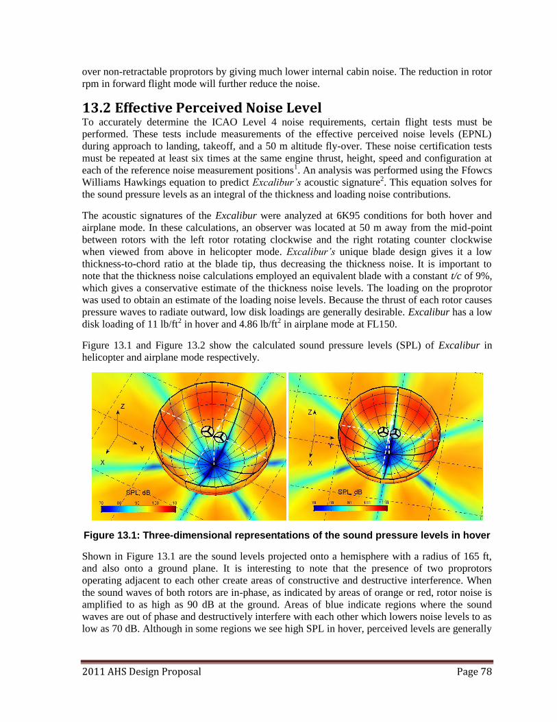
2011 AHS Design Proposal Page 78
over non-retractable proprotors by giving much lower internal cabin noise. The reduction in rotor
rpm in forward flight mode will further reduce the noise.
13.2 Effective Perceived Noise Level To accurately determine the ICAO Level 4 noise requirements, certain flight tests must be
performed. These tests include measurements of the effective perceived noise levels (EPNL)
during approach to landing, takeoff, and a 50 m altitude fly-over. These noise certification tests
must be repeated at least six times at the same engine thrust, height, speed and configuration at
each of the reference noise measurement positions1. An analysis was performed using the Ffowcs
Williams Hawkings equation to predict Excalibur’s acoustic signature2. This equation solves for
the sound pressure levels as an integral of the thickness and loading noise contributions.
The acoustic signatures of the Excalibur were analyzed at 6K95 conditions for both hover and
airplane mode. In these calculations, an observer was located at 50 m away from the mid-point
between rotors with the left rotor rotating clockwise and the right rotating counter clockwise
when viewed from above in helicopter mode. Excalibur’s unique blade design gives it a low
thickness-to-chord ratio at the blade tip, thus decreasing the thickness noise. It is important to
note that the thickness noise calculations employed an equivalent blade with a constant t/c of 9%,
which gives a conservative estimate of the thickness noise levels. The loading on the proprotor
was used to obtain an estimate of the loading noise levels. Because the thrust of each rotor causes
pressure waves to radiate outward, low disk loadings are generally desirable. Excalibur has a low
disk loading of 11 lb/ft2 in hover and 4.86 lb/ft2 in airplane mode at FL150.
Figure 13.1 and Figure 13.2 show the calculated sound pressure levels (SPL) of Excalibur in
helicopter and airplane mode respectively.
Figure 13.1: Three-dimensional representations of the sound pressure levels in hover
Shown in Figure 13.1 are the sound levels projected onto a hemisphere with a radius of 165 ft,
and also onto a ground plane. It is interesting to note that the presence of two proprotors
operating adjacent to each other create areas of constructive and destructive interference. When
the sound waves of both rotors are in-phase, as indicated by areas of orange or red, rotor noise is
amplified to as high as 90 dB at the ground. Areas of blue indicate regions where the sound
waves are out of phase and destructively interfere with each other which lowers noise levels to as
low as 70 dB. Although in some regions we see high SPL in hover, perceived levels are generally
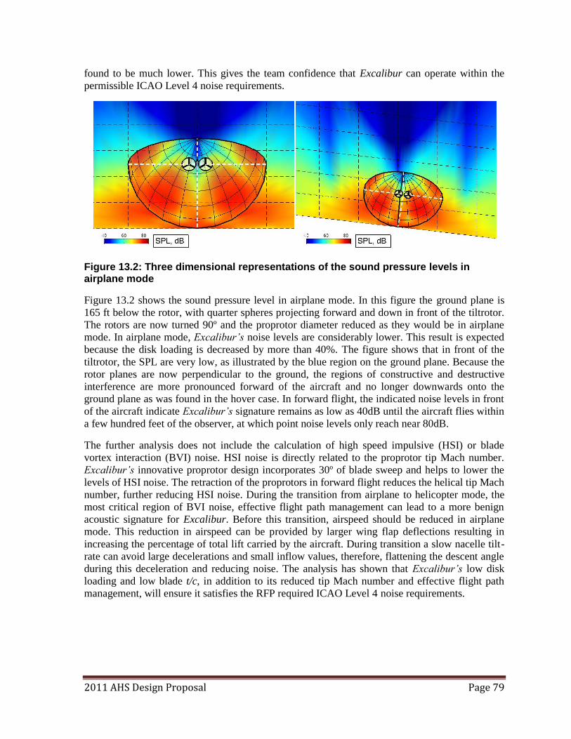
2011 AHS Design Proposal Page 79
found to be much lower. This gives the team confidence that Excalibur can operate within the
permissible ICAO Level 4 noise requirements.
Figure 13.2: Three dimensional representations of the sound pressure levels in airplane mode
Figure 13.2 shows the sound pressure level in airplane mode. In this figure the ground plane is
165 ft below the rotor, with quarter spheres projecting forward and down in front of the tiltrotor.
The rotors are now turned 90º and the proprotor diameter reduced as they would be in airplane
mode. In airplane mode, Excalibur’s noise levels are considerably lower. This result is expected
because the disk loading is decreased by more than 40%. The figure shows that in front of the
tiltrotor, the SPL are very low, as illustrated by the blue region on the ground plane. Because the
rotor planes are now perpendicular to the ground, the regions of constructive and destructive
interference are more pronounced forward of the aircraft and no longer downwards onto the
ground plane as was found in the hover case. In forward flight, the indicated noise levels in front
of the aircraft indicate Excalibur’s signature remains as low as 40dB until the aircraft flies within
a few hundred feet of the observer, at which point noise levels only reach near 80dB.
The further analysis does not include the calculation of high speed impulsive (HSI) or blade
vortex interaction (BVI) noise. HSI noise is directly related to the proprotor tip Mach number.
Excalibur’s innovative proprotor design incorporates 30º of blade sweep and helps to lower the
levels of HSI noise. The retraction of the proprotors in forward flight reduces the helical tip Mach
number, further reducing HSI noise. During the transition from airplane to helicopter mode, the
most critical region of BVI noise, effective flight path management can lead to a more benign
acoustic signature for Excalibur. Before this transition, airspeed should be reduced in airplane
mode. This reduction in airspeed can be provided by larger wing flap deflections resulting in
increasing the percentage of total lift carried by the aircraft. During transition a slow nacelle tilt-
rate can avoid large decelerations and small inflow values, therefore, flattening the descent angle
during this deceleration and reducing noise. The analysis has shown that Excalibur’s low disk
loading and low blade t/c, in addition to its reduced tip Mach number and effective flight path
management, will ensure it satisfies the RFP required ICAO Level 4 noise requirements.
2011 AHS Design Proposal Page 80
14 Survivability
Within the military setting, survivability is defined as the ability to remain mission capable after
a single engagement. It is important that, for a military vehicle, survivability is not addressed
solely by trying to protect the vehicle itself, but by safeguarding the crew1. This is accomplished
by ensuring occupants are protected not only by the effects of being hit by a projectile, but by
decreasing the likelihood of being detected, identified, and hit, as well as by minimizing post-hit
effects and increasing damage control.
14.1 Susceptibility The Excalibur significantly reduces the likelihood of being detected, identified, and hit by an
enemy fire. The main advantage comes from the performance of the aircraft. The Excalibur flies
at a higher altitude with a greater range and speed than most other VTOL aircraft. Cruising at
15,000 ft ensures that most weapons fired from the ground, including small weapons, cannon,
and RPG fire cannot reach the aircraft. Its ability to fly like an airplane reduces the visual and
acoustic signature of the aircraft and increases its maneuverability over traditional helicopter
configurations, giving it the ability to evade the enemy more easily.
14.2 Vulnerability Many features have been built into the Excalibur to reduce its vulnerability. The biggest
advantage is the ability to operate one engine inoperative (OEI). This is accomplished through an
interconnected drive shaft so that during normal operation it ensures that both rotors are turning
at the same rate. In an emergency, such a system can be utilized to drive the opposite rotor if that
rotor engine has malfunctioned. This shaft has also been designed large enough and strong
enough that it can also be pierced by a 50 mm round and continue to function. This redundancy
ensures that in the unlikely event that an engine becomes damaged and fails, the Excalibur can
continue flying long enough to land safely. This capability, coupled with an excellent
autorotational capability, ensures that even if both engines fail, the aircraft can be landed safely
in either airplane mode or helicopter mode, providing an unprecedented capability for a tiltrotor
concept. Redundancy in design is built into many of the vehicles systems as many are triple
redundant and most of the avionics, sensors, and displays are quadruple redundant.
Fire-protection and suspension are also built in features as all aspects. The vehicle incorporates a
dry bay with engine fire-suppression which reduces the likelihood of an engine fire spreading to
other parts of the vehicle. The fuel systems are also self-sealing and if the fuel system
experiences a break in the line, a fire will not break out. Fuel bladder tanks are also self-sealing
and conform to MIL-DTL-27422 specs, which include a crashworthiness requirement.
14.3 Recoverability The vehicle‘s recoverability refers to its ability to mitigate the effects of a post-critical event.
This means that after an emergency or failure has occurred, the post-crash danger must be
minimized. The Excalibur does this in much the same way that other military aircraft do. The
aircraft utilizes a remote mass design, such as engines and transmission at the wing tips, which
ensures that the wing undergoes controlled failure by separating at the cantilever of the
fuselage/wing intersection. This design feature alleviates the potential fuselage crushing that
might occur if there was transmission or engine mass above the fuselage. The composite
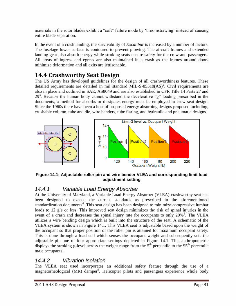
2011 AHS Design Proposal Page 81
materials in the rotor blades exhibit a ―soft‖ failure mode by ‗broomstrawing‘ instead of causing
entire blade separation.
In the event of a crash landing, the survivability of Excalibur is increased by a number of factors.
The fuselage lower surface is contoured to prevent plowing. The aircraft frames and extended
landing gear also absorb energy while stroking seats ensure safety for the crew and passengers.
All areas of ingress and egress are also maintained in a crash as the frames around doors
minimize deformation and all exits are jettisonable.
14.4 Crashworthy Seat Design The US Army has developed guidelines for the design of all crashworthiness features. These
detailed requirements are detailed in mil standard MIL-S-85510(AS)2. Civil requirements are
also in place and outlined in SAE, AS8049 and are also established in CFR Title 14 Parts 27 and
293. Because the human body cannot withstand the decelerative ―g‖ loading prescribed in the
documents, a method for absorbs or dissipates energy must be employed in crew seat design.
Since the 1960s there have been a host of proposed energy absorbing designs proposed including,
crushable column, tube and die, wire benders, tube flaring, and hydraulic and pneumatic designs.
Figure 14.1: Adjustable roller pin and wire bender VLEA and corresponding limit load adjustment setting
14.4.1 Variable Load Energy Absorber At the University of Maryland, a Variable Load Energy Absorber (VLEA) crashworthy seat has
been designed to exceed the current standards as prescribed in the aforementioned
standardization documents4. This seat design has been designed to minimize compressive lumbar
loads to 12 g‘s or less. This improved seat design minimizes the risk of spinal injuries in the
event of a crash and decreases the spinal injury rate for occupants to only 20%5. The VLEA
utilizes a wire bending design which is built into the structure of the seat. A schematic of the
VLEA system is shown in Figure 14.1. This VLEA seat is adjustable based upon the weight of
the occupant so that proper position of the roller pin is attained for maximum occupant safety.
This is done through a load cell which senses the occupant weight and subsequently sets the
adjustable pin one of four appropriate settings depicted in Figure 14.1. This anthropometric
displays the stroking g-level across the weight range from the 5th percentile to the 95th percentile
male occupants.
14.4.2 Vibration Isolation The VLEA seat used incorporates an additional safety feature through the use of a
magnetorheological (MR) damper6. Helicopter pilots and passengers experience whole body
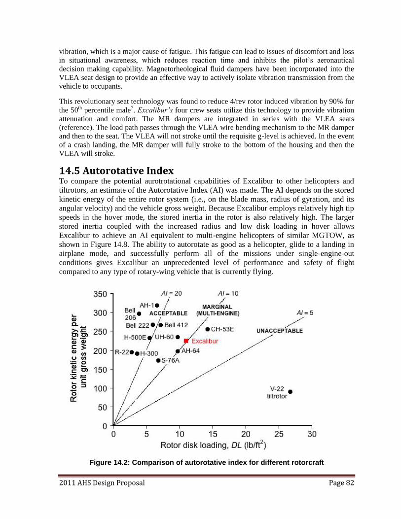
2011 AHS Design Proposal Page 82
vibration, which is a major cause of fatigue. This fatigue can lead to issues of discomfort and loss
in situational awareness, which reduces reaction time and inhibits the pilot‘s aeronautical
decision making capability. Magnetorheological fluid dampers have been incorporated into the
VLEA seat design to provide an effective way to actively isolate vibration transmission from the
vehicle to occupants.
This revolutionary seat technology was found to reduce 4/rev rotor induced vibration by 90% for
the 50th percentile male7. Excalibur’s four crew seats utilize this technology to provide vibration
attenuation and comfort. The MR dampers are integrated in series with the VLEA seats
(reference). The load path passes through the VLEA wire bending mechanism to the MR damper
and then to the seat. The VLEA will not stroke until the requisite g-level is achieved. In the event
of a crash landing, the MR damper will fully stroke to the bottom of the housing and then the
VLEA will stroke.
14.5 Autorotative Index To compare the potential aurotrotational capabilities of Excalibur to other helicopters and
tiltrotors, an estimate of the Autorotative Index (AI) was made. The AI depends on the stored
kinetic energy of the entire rotor system (i.e., on the blade mass, radius of gyration, and its
angular velocity) and the vehicle gross weight. Because Excalibur employs relatively high tip
speeds in the hover mode, the stored inertia in the rotor is also relatively high. The larger
stored inertia coupled with the increased radius and low disk loading in hover allows
Excalibur to achieve an AI equivalent to multi-engine helicopters of similar MGTOW, as
shown in Figure 14.8. The ability to autorotate as good as a helicopter, glide to a landing in
airplane mode, and successfully perform all of the missions under single-engine-out
conditions gives Excalibur an unprecedented level of performance and safety of flight
compared to any type of rotary-wing vehicle that is currently flying.
Figure 14.2: Comparison of autorotative index for different rotorcraft
2011 AHS Design Proposal Page 83
14.6 Assessment of Failure Modes Excalibur has been designed to ensure safety for various failure modes that could be encountered.
The response of the system to the major failure modes is outlined as follows:
Each of Excalibur’s nacelles is equipped with a tilt sensor. In the event that one of Excalibur’s
nacelles fails to tilt, the health and usage monitoring system detects the difference between the
two tilt sensors and sends a warning to the pilot. If this angle exceeds 5º, the HUMS
automatically stops further tilting of the nacelles. The difference in thrust between the two rotors
can be countered by the pilot through rudder and stick input until the aircraft can be trimmed.
A failure of the blade retraction mechanism on both rotors, or the failure of a single blade or rotor
to extend or retract is also detected by the HUMS. If a failure were to occur in the airplane mode,
both rotors remain in the previous position and a landing in airplane or STOL mode can be
performed at a suitable location. If the failure of the retraction mechanism occurs in helicopter
mode, an immediate landing is not necessary, as the vehicle can continue to fly and a landing
performed at best possible location.
As previously discussed in Section 5.3.4, the blade collective pitch has two ranges, one for hover
and one for forward flight. These collective settings utilize a solenoid mechanism to lock the
pitch bearings in their respective range positions. During nacelle tilt, and upon reaching the 45º
position, pitch range transitions to the respective position. The solenoid then locks the assembly
in this position. If the solenoid fails to lock in the new position, further nacelle tilting is halted.
The HUMS will then alert the pilot of the failure and the assembly will attempt to lock in the
previous position. If this also results in a locking failure and a return to base or animmediate
landing must be performed.
In the case of a single engine failure, the interconnecting shaft between the two rotors will be
able to power both the rotors in helicopter and airplane mode. In the case of helicopter mode, the
pilot should land in the closest possible location because the power required to hover cannot
be sufficed by a single operative engine. However, in airplane mode, Excalibur can continue to
fly at the best range speed or lowest power required.
In the event of dual engine failure in helicopter mode, Excalibur can autorotate as it has an
autorotative index of 10. If the dual engines fail in airplane mode, Excalibur can glide to the
nearest suitable landing location at its best glide speed.
If the landing gear fails to extended, the pilots can utilize a manual gear lever in an attempt to
lower it. The weight of the gear should cause it to extend and lock into place while automatically
pushing open the gear bay doors. A gear lock indicator on the pilots multi-function display shows
green lights or red lights, indicating the gear is in a safe or unsafe position to land.
15 Project Development Timeline
15.1 Life-Cycle Cost Analysis The cost of a tiltrotor, as with any other aircraft is divided into various categories: development
cost, production cost, and operational costs. These categories add up to the total life-cycle cost of
the vehicle. Often, the customer will only see two areas of cost for the aircraft, mainly the
acquisition cost and the operational costs. Acquisition cost is the sum of the development and
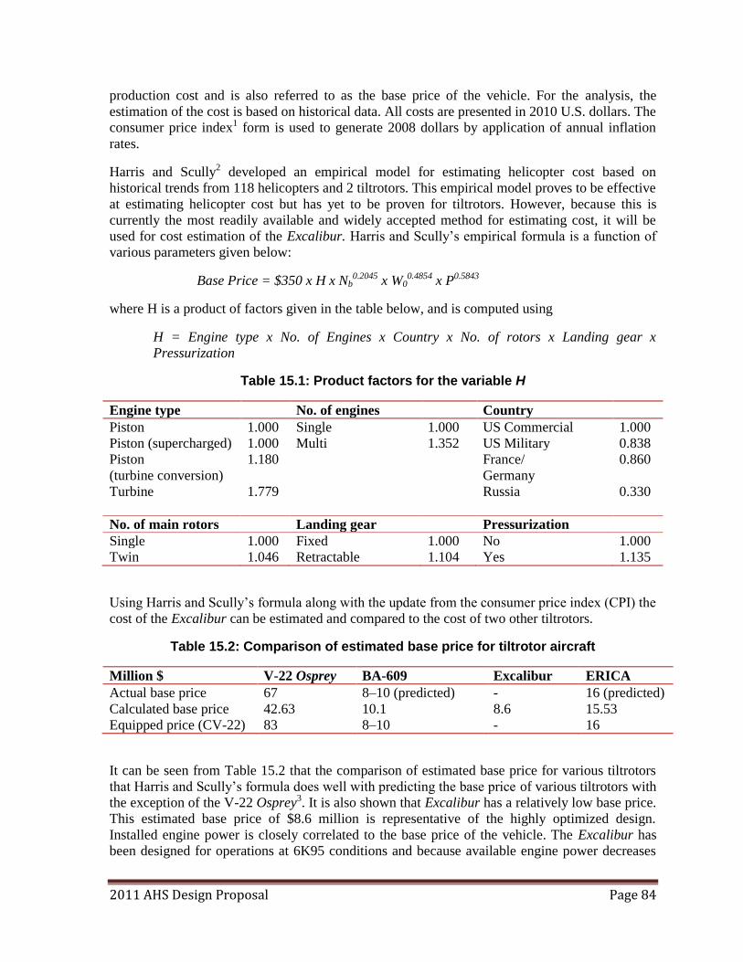
2011 AHS Design Proposal Page 84
production cost and is also referred to as the base price of the vehicle. For the analysis, the
estimation of the cost is based on historical data. All costs are presented in 2010 U.S. dollars. The
consumer price index1 form is used to generate 2008 dollars by application of annual inflation
rates.
Harris and Scully2 developed an empirical model for estimating helicopter cost based on
historical trends from 118 helicopters and 2 tiltrotors. This empirical model proves to be effective
at estimating helicopter cost but has yet to be proven for tiltrotors. However, because this is
currently the most readily available and widely accepted method for estimating cost, it will be
used for cost estimation of the Excalibur. Harris and Scully‘s empirical formula is a function of
various parameters given below:
Base Price = $350 x H x Nb0.2045 x W0
0.4854 x P0.5843
where H is a product of factors given in the table below, and is computed using
H = Engine type x No. of Engines x Country x No. of rotors x Landing gear x
Pressurization
Table 15.1: Product factors for the variable H
Engine type No. of engines Country
Piston 1.000 Single 1.000 US Commercial 1.000
Piston (supercharged) 1.000 Multi 1.352 US Military 0.838
Piston
(turbine conversion)
1.180 France/
Germany
0.860
Turbine 1.779 Russia 0.330
No. of main rotors Landing gear Pressurization
Single 1.000 Fixed 1.000 No 1.000
Twin 1.046 Retractable 1.104 Yes 1.135
Using Harris and Scully‘s formula along with the update from the consumer price index (CPI) the
cost of the Excalibur can be estimated and compared to the cost of two other tiltrotors.
Table 15.2: Comparison of estimated base price for tiltrotor aircraft
Million $ V-22 Osprey BA-609 Excalibur ERICA
Actual base price 67 8–10 (predicted) - 16 (predicted)
Calculated base price 42.63 10.1 8.6 15.53
Equipped price (CV-22) 83 8–10 - 16
It can be seen from Table 15.2 that the comparison of estimated base price for various tiltrotors
that Harris and Scully‘s formula does well with predicting the base price of various tiltrotors with
the exception of the V-22 Osprey3. It is also shown that Excalibur has a relatively low base price.
This estimated base price of $8.6 million is representative of the highly optimized design.
Installed engine power is closely correlated to the base price of the vehicle. The Excalibur has
been designed for operations at 6K95 conditions and because available engine power decreases
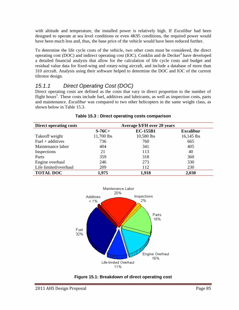
2011 AHS Design Proposal Page 85
with altitude and temperature, the installed power is relatively high. If Excalibur had been
designed to operate at sea level conditions or even 4K95 conditions, the required power would
have been much less and, thus, the base price of the vehicle would have been reduced further.
To determine the life cycle costs of the vehicle, two other costs must be considered, the direct
operating cost (DOC) and indirect operating cost (IOC). Conklin and de Decker4 have developed
a detailed financial analysis that allow for the calculation of life cycle costs and budget and
residual value data for fixed-wing and rotary-wing aircraft, and include a database of more than
310 aircraft. Analysis using their software helped to determine the DOC and IOC of the current
tiltrotor design.
15.1.1 Direct Operating Cost (DOC) Direct operating costs are defined as the costs that vary in direct proportion to the number of
flight hours5. These costs include fuel, additives and lubricants, as well as inspection costs, parts
and maintenance. Excalibur was compared to two other helicopters in the same weight class, as
shown below in Table 15.3.
Table 15.3 : Direct operating costs comparison
Direct operating costs Average $/FH over 20 years
S-76C+ EC-155B1 Excalibur
Takeoff weight 11,700 lbs 10,580 lbs 16,145 lbs
Fuel + additives 736 760 665
Maintenance labor 404 341 405
Inspections 21 113 40
Parts 359 318 360
Engine overhaul 246 273 330
Life limited/overhaul 209 112 230
TOTAL DOC 1,975 1,918 2,030
Figure 15.1: Breakdown of direct operating cost
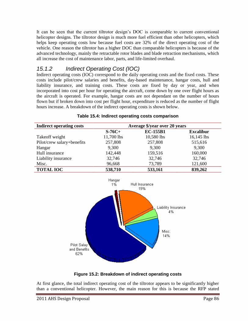
2011 AHS Design Proposal Page 86
It can be seen that the current tiltrotor design‘s DOC is comparable to current conventional
helicopter designs. The tiltrotor design is much more fuel efficient than other helicopters, which
helps keep operating costs low because fuel costs are 32% of the direct operating cost of the
vehicle. One reason the tiltrotor has a higher DOC than comparable helicopters is because of the
advanced technology, mainly the retractable rotor blades and blade retraction mechanisms, which
all increase the cost of maintenance labor, parts, and life-limited overhaul.
15.1.2 Indirect Operating Cost (IOC) Indirect operating costs (IOC) correspond to the daily operating costs and the fixed costs. These
costs include pilot/crew salaries and benefits, day-based maintenance, hangar costs, hull and
liability insurance, and training costs. These costs are fixed by day or year, and when
incorporated into cost per hour for operating the aircraft, come down by one over flight hours as
the aircraft is operated. For example, hangar costs are not dependant on the number of hours
flown but if broken down into cost per flight hour, expenditure is reduced as the number of flight
hours increase. A breakdown of the indirect operating costs is shown below.
Table 15.4: Indirect operating costs comparison
Indirect operating costs Average $/year over 20 years
S-76C+ EC-155B1 Excalibur
Takeoff weight 11,700 lbs 10,580 lbs 16,145 lbs
Pilot/crew salary+benefits 257,808 257,808 515,616
Hangar 9,300 9,300 9,300
Hull insurance 142,448 159,516 160,000
Liability insurance 32,746 32,746 32,746
Misc. 96,668 73,789 121,600
TOTAL IOC 538,710 533,161 839,262
Figure 15.2: Breakdown of indirect operating costs
At first glance, the total indirect operating cost of the tiltrotor appears to be significantly higher
than a conventional helicopter. However, the main reason for this is because the RFP stated
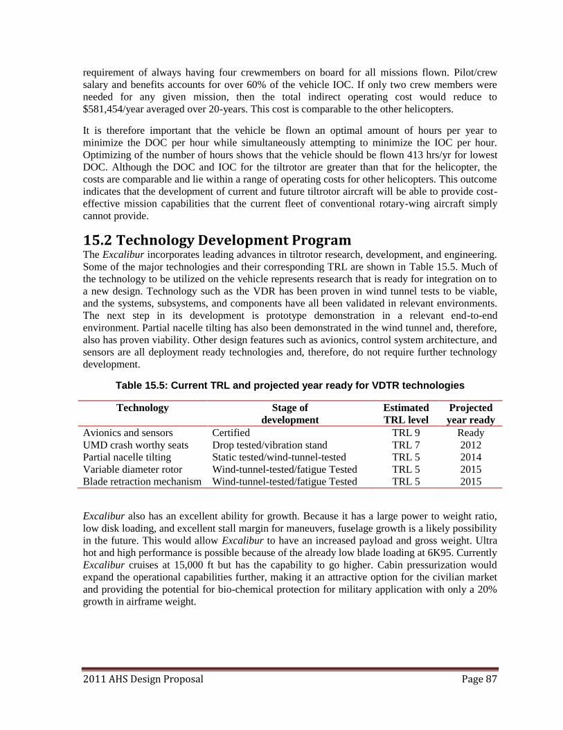
2011 AHS Design Proposal Page 87
requirement of always having four crewmembers on board for all missions flown. Pilot/crew
salary and benefits accounts for over 60% of the vehicle IOC. If only two crew members were
needed for any given mission, then the total indirect operating cost would reduce to
$581,454/year averaged over 20-years. This cost is comparable to the other helicopters.
It is therefore important that the vehicle be flown an optimal amount of hours per year to
minimize the DOC per hour while simultaneously attempting to minimize the IOC per hour.
Optimizing of the number of hours shows that the vehicle should be flown 413 hrs/yr for lowest
DOC. Although the DOC and IOC for the tiltrotor are greater than that for the helicopter, the
costs are comparable and lie within a range of operating costs for other helicopters. This outcome
indicates that the development of current and future tiltrotor aircraft will be able to provide cost-
effective mission capabilities that the current fleet of conventional rotary-wing aircraft simply
cannot provide.
15.2 Technology Development Program The Excalibur incorporates leading advances in tiltrotor research, development, and engineering.
Some of the major technologies and their corresponding TRL are shown in Table 15.5. Much of
the technology to be utilized on the vehicle represents research that is ready for integration on to
a new design. Technology such as the VDR has been proven in wind tunnel tests to be viable,
and the systems, subsystems, and components have all been validated in relevant environments.
The next step in its development is prototype demonstration in a relevant end-to-end
environment. Partial nacelle tilting has also been demonstrated in the wind tunnel and, therefore,
also has proven viability. Other design features such as avionics, control system architecture, and
sensors are all deployment ready technologies and, therefore, do not require further technology
development.
Table 15.5: Current TRL and projected year ready for VDTR technologies
Technology Stage of
development
Estimated
TRL level
Projected
year ready
Avionics and sensors Certified TRL 9 Ready
UMD crash worthy seats Drop tested/vibration stand TRL 7 2012
Partial nacelle tilting Static tested/wind-tunnel-tested TRL 5 2014
Variable diameter rotor Wind-tunnel-tested/fatigue Tested TRL 5 2015
Blade retraction mechanism Wind-tunnel-tested/fatigue Tested TRL 5 2015
Excalibur also has an excellent ability for growth. Because it has a large power to weight ratio,
low disk loading, and excellent stall margin for maneuvers, fuselage growth is a likely possibility
in the future. This would allow Excalibur to have an increased payload and gross weight. Ultra
hot and high performance is possible because of the already low blade loading at 6K95. Currently
Excalibur cruises at 15,000 ft but has the capability to go higher. Cabin pressurization would
expand the operational capabilities further, making it an attractive option for the civilian market
and providing the potential for bio-chemical protection for military application with only a 20%
growth in airframe weight.
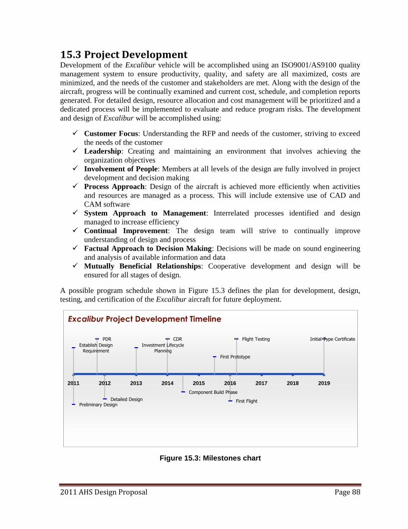
2011 AHS Design Proposal Page 88
15.3 Project Development Development of the Excalibur vehicle will be accomplished using an ISO9001/AS9100 quality
management system to ensure productivity, quality, and safety are all maximized, costs are
minimized, and the needs of the customer and stakeholders are met. Along with the design of the
aircraft, progress will be continually examined and current cost, schedule, and completion reports
generated. For detailed design, resource allocation and cost management will be prioritized and a
dedicated process will be implemented to evaluate and reduce program risks. The development
and design of Excalibur will be accomplished using:
Customer Focus: Understanding the RFP and needs of the customer, striving to exceed
the needs of the customer
Leadership: Creating and maintaining an environment that involves achieving the
organization objectives
Involvement of People: Members at all levels of the design are fully involved in project
development and decision making
Process Approach: Design of the aircraft is achieved more efficiently when activities
and resources are managed as a process. This will include extensive use of CAD and
CAM software
System Approach to Management: Interrelated processes identified and design
managed to increase efficiency
Continual Improvement: The design team will strive to continually improve
understanding of design and process
Factual Approach to Decision Making: Decisions will be made on sound engineering
and analysis of available information and data
Mutually Beneficial Relationships: Cooperative development and design will be
ensured for all stages of design.
A possible program schedule shown in Figure 15.3 defines the plan for development, design,
testing, and certification of the Excalibur aircraft for future deployment.
Figure 15.3: Milestones chart
Establish Design
Requirement
Preliminary Design
PDR
Detailed Design
Investment Lifecycle
Planning
CDR
Component Build Phase
First Prototype
First Flight
Flight Testing Initial Type Certificate
2011 2012 2013 2014 2015 2016 2017 2018 2019
Excalibur Project Development Timeline
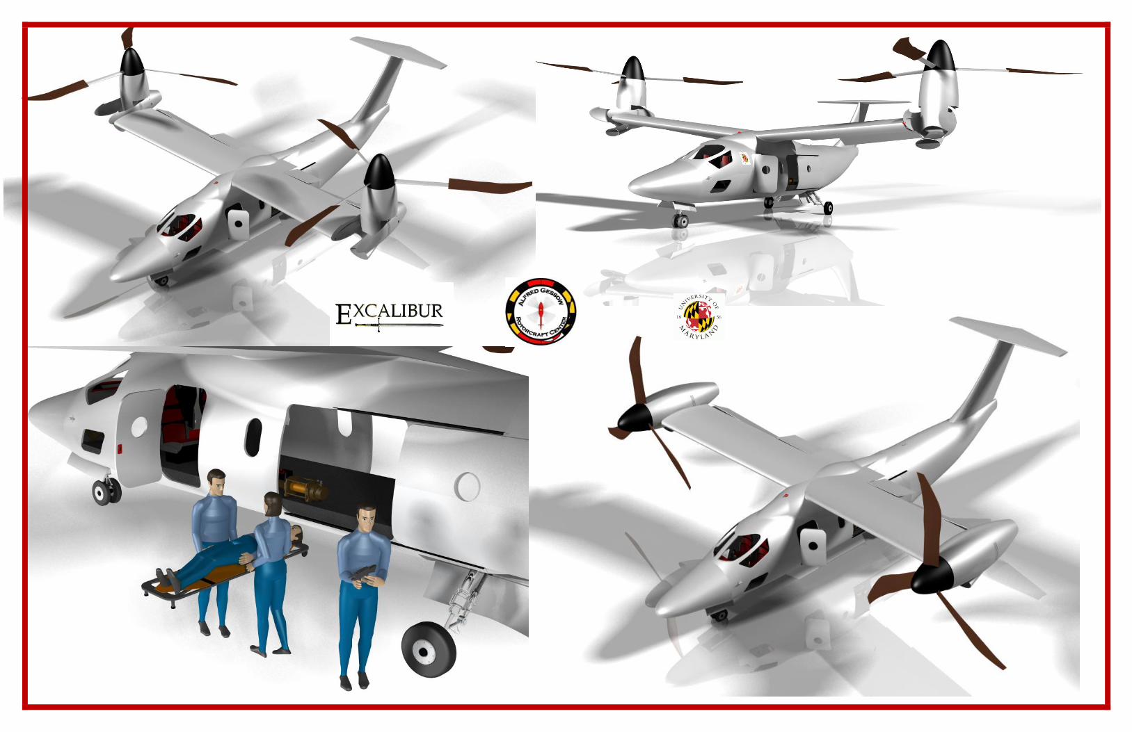
University of Maryland
Design Team 2011
2011 AHS Design Proposal Page 89
16 Summary
The 2011 Student Design Competition Request for Proposals issued by the American Helicopter
Society and Bell Helicopter Textron desired the development of a new multi-mission aircraft.
This report has outlined the proposed design of Excalibur, a highly innovative, multi-mission
variable diameter tiltrotor. Excalibur‘s design has been optimized to ensure the greatest multi-
mission flexibility making it the ideal vehicle for completing search and rescue, insertion, and
resupply missions. These three missions, based on the needs of current events, have diverse
performance requirements. Therefore, the design uses proven, cutting edge technologies to
simultaneously achieve both a highly efficient helicopter and an equally efficient airplane. This
gives Excalibur significant performance advantages over other vertical lift aircraft, with greater
range and endurance, while performing the missions in a timely manner. The ability to change
rotor diameter provides excellent propulsive efficiency in forward flight without sacrificing hover
efficiency.
The RFP specified the need for a new vertical lift aircraft with increased versatility, capable of
multiple missions. These missions include search and rescue, military insertion, and resupply.
Excalibur has also been designed to meet the requirements of hover at 6K95 at MGTOW with
sufficient stall margin for maneuvers. To meet these requirements, Excalibur has been designed
using a combination of cutting edge technologies including:
Variable Diameter Rotors
- Optimized to provide the best hovering efficiency and propulsive efficiency.
Power loading = 7 lb/hp (Section 5)
Propulsive efficiency = 11 lb/ft2 (Section 5)
- Excalibur is able to take off and land on runways like fixed-wing aircraft
- Increased payload capacity
4,000 lbs: Vertical Takeoff
6,000 lbs: Airplane Takeoff
- Autorotation Capability as good as multi-engine helicopters AI = 10 (Section 14.5)
Innovative Rotor and Hub Design
- Uses maintenance free elastomeric bearings to provide pitch articulation and blade
retention
- Contains a spooling motor, coupled with a Harmonic Drive to reel in the tension
strap for blade retraction
- Homo-kinetic gimbaled design relieves 1/rev blade flapping loads and virtually
eliminates Coriolis forces induced by blade flapping
Rotor Tilting Mechanism
- Engines remain horizontal and only the rotor and secondary transmission are tilted
- Simpler design as engine mounted accessories no longer need to be designed to
rotate at the nacelle
- Hot exhaust gasses are directed rearward and, therefore, do not burn takeoff surfaces
or injure persons under the vehicle while in hover
2011 AHS Design Proposal Page 90
Surpasses RFP Mission Requirements
- Mission 1: Search and Rescue
Payload = 1,200 lbs
Range = 450 nm
Speed: VBR = 220 kts, VMAX = 298 kts
- Mission 2: Insertion
Payload = 4,000 lbs
Range = 500 nm
Speed = 220 kts
- Mission 3: Resupply
Payload = 3,000 lbs
Range = 500 nm
Speed = 220 kts
Excalibur’s unmatched performance gives it a strategic advantage. Excalibur has high cruise
speed with the ability to cruise at 225 kts and dash at speeds of 330 kts with a longer range,
extending to distances of 500 nm. This makes it highly fuel efficient as Excalibur can fly further
and faster. HOGE capability at MGTOW and at 6K95 is unprecedented for current tiltrotor
technology. Low disk loadings, optimized blade design, and lower tip speeds ensures that
Excalibur will meet ICAO Level 4 noise requirements. All of the aircraft‘s features are driven to
ensure true multi-mission capability ensuring it can complete all missions more effectively than
any other VTOL aircraft. Excalibur represents a paradigm shift and provides a quantum leap
forward in tiltrotor utility and performance making it the cutting edge of tiltrotor technology.
2011 AHS Design Proposal Page 91
17 References
17.1 Section 1
17.2 Section 2 1. Product Innovation X-2 Technology. Sikorsky Aircraft. Web. 31 May 2011.
<http://www.sikorsky.com/Innovation/Vision+of+the+future/Technologies/X2+Techn
ology>.
2. Eurocopter: The X3 Concept. Eurocopter an EADS Company, 2011. Web. 14 Mar.
2011. <http://www.eurocopter.com/site/en/ref/X3-Demonstrator_1099.html>.
3. MartinD., Maisel, Giulianetti Demo J., and Frank Daniel C. "The History of the XV-15
Tilt Rotor Research Aircraft: From Concept to Flight ." NASA History Series
4. Leishman, J. G. "Is There a Case for the Tiltrotor?" RUSI Defence Systems October
(2007): 52-55.
17.3 Section 3 1. Tishchenko, M. N. and Nagaraj, V. T., ENAE 634 Helicopter Design Lecture Notes,
University of Maryland, College Park, 2008.
2. Johnson, W., "NDARC — NASA Design and Analysis of Rotorcraft Validation and
Demonstration." AHS on Aeromechanics Specialists, Jan 20-22, 2008, San Francisco,
CA.
3. Claudio, B., Charles, I., Henry, L., and Richard, P., ―Engine sizing : Lapse rate
reference: Methodology for estimating helicopter performance and weights using
limited data.‖, NASA Technical Memorandum 102824, April 1991
4. 24th Annual AHS Student Design Competition 2007 Request for Proposal (RFP),
sponsored by Sikorsky Corporation and AHS International
17.4 Section 4
17.5 Section 5 1. Keys, C. N. Rotoray-Wing Aerodynamics: Volume II - Performance Prediction of
Helicopters. Tech. Vol. 3083. Philadelphia: Boeing Vertol, 1979.
2. Winarto, Hadi. BEMT Algorithm for the Prediction of the Performance of Arbitrary
Propellers. Rep. Melbourne: Royal Melbourne Institute of Technology, 2004.
3. Evans, Albert J., and George Liner. A Wind-Tunnel Investigation of the
Aerodynamic Characteristics of a Full-Scale Supersonic-Type Three-Blade
Propeller at Mach Numbers to 0.96. Rep. NACA Research Memorandum, 1953.
4. Leishman, J. Gordon. Principles of Helicopter Aerodynamics. Cambridge:
Cambridge UP, 2006.
5. Matuska, David, Edward Gronenthal, and Donald Jepson. Torque Tube/Spar
Assembly for Variable Diameter Helicopter Rotors. Sikorsky Aircraft Corporation,
assignee. Patent 5636969. 10 June 1997.
6. Matuska, David, and Edward Gronenthal. Retraction/Extiension Mechanism for
Variable Diameter Rotors. Sikorsky Aircraft Corporation, assignee. Patent
5642982. 1 July 1997.
2011 AHS Design Proposal Page 92
7. Balayn, Frederick, and Eric Magre. Convertabel Aircraft with Tilting Rotors.
Eurocopter, assignee. Patent 6260793. 17 July 2001. 8. Balayn, Frederic, and Eric Magre. Convertabel Aircraft with Tilting Rotors.
Eurocopter, assignee. Patent 6276633. 21 Aug. 2001.
9. Federici, Francis, and Francis Byrnes. Blade Lock System for Variable Diameter Rotor
System. Sikorsky Aircraft Corporation, assignee. Patent 6398497. 4 June 2002.
10. Warwick, Graham. "DiscRotor: What Goes Round Could Go Faster." Aviation Week. 4
Aug. 2008. Web. <http://www.aviationweek.com/>.
11. Germanowski, Peter, Brandon Stille, and Michael Strauss. Technology Assessment for
Large Vertical-Lift Transport Tiltrotors. Rep. no. NASA/CR-2010-216384. Stratford,
CT: Sikorsky Aircraft Corporation, 2010
12. Matuska, David, Edward Gronenthal, and Donald Jepson. Torque Tube/Spar
Assembly for Variable Diameter Helicopter Rotors. Sikorsky Aircraft Corporation,
assignee. Patent 5636969. 10 June 1997.
13. Matuska, David, and Edward Gronenthal. Retraction/Extiension Mechanism for
Variable Diameter Rotors. Sikorsky Aircraft Corporation, assignee. Patent
5642982. 1 July 1997. 14. Harmonic Drive Gearing, Harmonic Planetary Gearing, Rotary Actuators ::
Harmonic Drive LLC. Web. 31 May 2011. <http://www.harmonicdrive.net/>.
17.6 Section 6 1. Harmonic Drive Gearing, Harmonic Planetary Gearing, Rotary Actuators ::
Harmonic Drive LLC. Web. 31 May 2011. <http://www.harmonicdrive.net/>.
2. 24th Annual AHS Student Design Competition 2007 Request for Proposal (RFP),
sponsored by Sikorsky Corporation and AHS International
3. "Sprag Clutch." Renold Plc - Manufacturer of Chain, Gears and Couplings. Web. 15
Mar. 2011. <http://www.renold.com.>
4. Dudley, Darle W. Handbook of Practical Gear Design. Boca Raton: CRC, 2002.
Print.
17.7 Section 7 1. Barkai, S. M., O. Rand, R. J. Peyran, and R. M. Carlson. "Modeling and Analysis
of Tilt-Rotor Aeromechanical Phenomena." Mathematical Computational
Modeling 27.12 (1998): 17-43.
2. Barkai, Shirley M., and Omri Rand. "The Influence of Composite Induced
Couplings on Tiltrotor Whirl Flutter Stability." Journal of the American Helicopter
Society 43.2 (1998): 133.
3. Eden, Paul E., and Soph Moeng. Modern Military Aircraft Anatomy: Technical
Drawings of 118 Aircraft, 1945 to the Present Day. London: Amber, 2007.
4. Donaldson, Bruce K. Analysis of Aircraft Structures: an Introduction. Cambridge:
Cambridge Univ., 2008. 5. [Bush et. al. 08] Bush, Brandon et. al.,―The Volterra-Environmentally Friendly VTOL
Concept Design: ―Volterra,‖ American Helicopter Society Student Design Competition
2008.
6. Raymer, Daniel P. Aircraft Design: a Conceptual Approach. Reston, VA:
American Institute of Aeronautics and Astronautics, 2006.
2011 AHS Design Proposal Page 93
7. Hrusch, Louis. Articulated Main Landing Gear. Pneumo Corporation, assignee.
Patent 3951361. 20 Apr. 1976.
17.8 Section 8 1. "Adaptive Flight Displays." Rockwell Collins - ADF. 2011. Web. 31 Mar. 2011.
<http://www.rockwellcollins.com>.
2. "Military Headsets." David Clark: Headset Communication Systems for High-Noise
Environments. 2011. Web. Apr. 2011. <http://www.davidclark.com>.
3. Muldoon, Richard, John Gill, and Larry Brock. "Integrated Mechanical Diagnostic
(IMD) Health and Usage Monitoring System (HUMS): An Open System
Implementation Case Study." IEEE (1999).
17.9 Section 9 1. Maisel, Martin, comp. NASA/Army XV-15 Tilt Rotor Research Aircraft
Familiarizaiton Document. Tech. Vol. TM X-62, 407. Moffett Field: Ames
Research Center and U.S. Army Air Mobility R&D Laboratory, 1975. 2. Maisel, Martin D., Demo J. Giulianetti, and Daniel C. Dugan. The History of the XV-15
Tilt Rotor Research Aircraft: from Concept to Flight. Washington, D.C.: National
Aeronautics and Space Administration, Office of Policy and Plans, NASA History
Division, 2000.
3. United States of America. Department of Transportation. Federal Aviation
Administration. Federal Aviation Regulations. Vol. 14 CFR. 2011.
4. Rozovski, David, and Terry Von Thaden. Control Reversal Mitigation and
Situational Awareness Improvement for Tiltrotor Aircraft Pilots Via Re-Design of
the Thrust/Power Control Interface. Tech. Savory, IL: Human Factors Division
Institue of Aviation, UIUC, 2008. 5. Rand, Omri. RaPID. Technion City, Haifa, Israel: Rand Technologies and Engineering,
2011. Computer software.
6. United States of America. United States Army Aviation and Missile Command.
Aviation Engineering Directorate. Aeronautical Design Standard Performance
Specification Handling Qualities Requirements for Military Rotorcraft. Vol. ADS-
33E-PRF. Redstone Arsenal, 2000.
7. Kleinhesselink, Kristi M. Stability and Control Modeling of Tiltrotor Aircraft.
Thesis. Department of Aerospace Engineering, University of Maryland, College
Park, 2007. University of Maryland, 2007.
17.10 Section 10 1. United States of America. Department of Defense. Department of the Army. Army
Helicopter Internal Load Operations. Vol. FM 55-450-2. Washington, D.C., 1992.
2. "Mobile Military." Pelican Case. Web. May 2011. <http://www.pelican.com/>.
17.11 Section 11
17.12 Section 12 1. Stettnar, M., and D.P. Scharge. "Tiltrotor Performance Sensitivities for
Multidiscplinary Wing Optimization,‖ AHS on Rotorcraft Mechanics Optimization,
Jan 23-25, 2008, San Francisco, CA.
2011 AHS Design Proposal Page 94
2. Rotorcraft Conceptual Design Environment. Proc. of The 3rd International Basic
Research Conference on Rotorcraft Technology, Nanjing, China. Nanjing, 2009.
14-16.
3. Leishman, J. G., and Kenneth M. Rosen. "Challenges in the Aerodynamic
Optimization of High-Efficiency Proprotors." Journal of the American Helicopter
Society 56 (2011). Web. Mar. 2011.
4. Winarto, Hadi. BEMT Algorithm for the Prediction of the Performance of Arbitrary
Propellers. Rep. Melbourne: Royal Melbourne Institute of Technology, 2004. 5. Leishman, J. G., Principles of Helicopter Aerodynamics, Cambridge University Press,
Cambridge, 2006
17.13 Section 13 1. Gervais, M.,‖Tiltorotor Noise Reduction Through Flight Trajectory Management and
Aircraft Configuration Control.‖ Ph.D. Dissertation, University of Maryland, College
Park, 2004.
2. Brentner, K. S., and Farassat, F., ―Modeling Aerodynamically Generated Sound of
Helicopter Rotors,‖
3. Ahuja, K.K., ―Tiltrotor Aircraft Noise – A Summary of the Research and Development
Service Presentations and Washington, D.C. 20591‖ Discussions At The 1991
FAA/GA Tech Workshop
17.14 Section 14 1. Laramee, Robert. V-22 Integrated Survivability Design Approach. Publication.
Aircraft Survivability.
2. Desjardins, Stanley. American Helicopter Society 59th Annual Forum. Proc. of The
Evolution of Energy Absorption Systems for Crashworthy Helicopter Seats,
Tempe. Pheonix: AHS International, 2003.
3. Hiemenz, Gregory J., Norman M. Wereley, and Curt Kothera. Adaptive Energy
Absorption System for a Vehicle Seat. Patent US 2010/0179730. 15 July 1020.
4. Hiemenz, Gregory J., Wei Hu, Grum Ngatu, and Norman Wereley. Rotoray Vane
Magnetorheological (MR) Energy Absorber. Patent US 2010/0300819. 2 Dec.
2010.
5. Hiemenz, Gregory, Wei Hu, and Norman Wereley. Semi-Active
Magnetorheological Helicopter Crew Seat Suspension for Vibration Isolation. Rep.
American Institue of Aeronautics and Astronautics, 2007.
17.15 Section 15 1. U.S. Department of Labor, Consumer Price Index, Bureau of Labor Statistics,
Washington D.C.
2. Harris, F. D. and Scully, M. P., ―Supplemental Appendix : Helicopters Cost Too
Much,‖ American Helicopter Society 53rd Annual Forum, Virginia Beach, Virginia,
April, 1997.
3. Conklin and De Decker Associates. The Aircraft Comparator: Helicopter Life Cycle
Cost. Computer software.
4. Harris, F. D. and Scully, M. P., ―Helicopters Cost Too Much,‖ American Helicopter
Society 53rd Annual Forum, Virginia Beach, Virginia, April, 1997