Embed Size (px)
Citation preview
Performance and Design Investigation of Heavy Lift Tiltrotor with AerodynamicInterference Effects
Hyeonsoo Yeo
Aeroflightdynamics Directorate (AMRDEC)U.S. Army Research, Development, and Engineering Command
Ames Research Center, Moffett Field, California
Wayne Johnson
Aeromechanics BranchNASA Ames Research Center
Moffett Field, California
Abstract
The aerodynamic interference effects on tiltrotor performance in cruise are investigated using comprehensivecalculations, to better understand the physics and to quantify the effects on the aircraft design. Performancecalculations were conducted for 146,600-lb conventional and quad tiltrotors, which are to cruise at 300knots at 4000 ft/95 deg F condition. A parametric study was conducted to understand the effects of designparameters on the performance of the aircraft. Aerodynamic interference improves the aircraft lift-to-dragratio of the baseline conventional tiltrotor. However, interference degrades the aircraft performance of thebaseline quad tiltrotor, due mostly to the unfavorable effects from the front wing to the rear wing. A reductionof rotor tip speed increased the aircraft lift-to-drag ratio the most among the design parameters investigated.
Notation
A rotor disk areaCW rotor weight coefficiente Oswald efficiency factorL/D = WV/P aircraft effective lift-to-drag ratioP aircraft powerq dynamic pressureR rotor radiusS wing areaV flight speedW gross weightW/A disk loadingW/S wing loadingσ solidity (thrust weighted)
Introduction
The recent NASA Heavy Lift Rotorcraft SystemsInvestigation [1] and on-going Joint Heavy Lift (JHL)Concept Design and Analysis (CDA) have renewedthe interest in heavy lift aircraft for both civil andmilitary applications. A tiltrotor aircraft configurationhas the potential to combine vertical take-off andlanding capability with efficient, high-speed cruise flight.
Presented at the American Helicopter Society 63rd Annual Forum,Virginia Beach, VA, May 1-3, 2007. This material is declared a workof the U.S. Government and is not subject to copyright protection in theUnited States.
Accurate prediction of aircraft performance is essentialfor the design of future rotorcraft. It is necessaryto incorporate rotor/rotor, rotor/wing, and wing/winginterference effects in the performance calculations. Theadvent of a quad tiltrotor (two wings and four rotors) hasincreased the importance of aerodynamic interference.
There have been many studies on the aerodynamicinteractions between rotor and wing of a conventionaltiltrotor in hover due to a significant wing download andits implication on hover performance [2–4]. After BellHelicopter proposed the development of Quad Tiltrotor(QTR) [5], researchers conducted both experiments [6,7] and analysis using computational fluid dynamics(CFD) [8, 9].
The current study investigates the aerodynamicinterference effects on tiltrotor performance in cruiseusing comprehensive calculations, with the objectiveto better understand the physics and to quantify theeffects on the aircraft design. In this paper, performancecalculations were conducted for 146,600-lb conventionaland quad tiltrotors, which are to cruise at 300 knots at4000 ft/95 deg F condition. A parametric study wasconducted to understand the effects of design parameterson the performance of the aircraft.
Tiltrotor Modeling and Analysis
The baseline conventional tiltrotor considered is a 20-ton payload tiltrotor, which is to cruise at 300 knots
1
https://ntrs.nasa.gov/search.jsp?R=20070017930 2018-02-12T05:10:20+00:00Z
at 4000 ft/95 deg F condition. The configurationof the baseline tiltrotor is shown in Fig. 1. Theaircraft has two four-bladed tilting rotors at the wingtips, a high wing, and a horizontal tail. The basicsize of the aircraft was determined using the U.S.Army Aeroflightdynamics Directorate’s design codeRC [11]. Aircraft performance was calculated withthe comprehensive rotorcraft analysis CAMRAD II [12],which has demonstrated good performance and airloadscorrelation with test data [13]. The characteristics of thebaseline tiltrotor are summarized in Table 1. The baselineaircraft design parameters are disk loading of W/A = 15lb/ft2, blade loading of CW
�σ = 0.14, and wing loading
of W/S = 100 lb/ft2. The airframe and wing parasite dragis D/q = 55 ft2. This drag value is considered aggressivein terms of rotorcraft trends but achievable from goodfixed wing aerodynamic design practice. A hingelessrotor hub was used, with a first blade flap frequency of1.105/rev. The rotor was modeled as a rigid blade witha flap hinge. Wing and airframe elastic motion was notconsidered. The rotors rotate with the top blades movingoutward in airplane mode.
The baseline quad tiltrotor is developed (not designedby the design code RC) from the baseline conventionaltiltrotor, having the same gross weight, disk loading,and airframe size. The configuration of the baselinequad tiltrotor is shown in Fig. 2. The characteristics ofthe baseline quad tiltrotor are summarized in Table 2.The rotor size was determined to maintain same diskloading as the baseline conventional tiltrotor. The frontwing span followed from maintaining the same clearancebetween the two rotors, and the front wing chord wasdetermined by maintaining the same aspect ratio as thebaseline conventional tiltrotor wing. The rear wing spanwas chosen as 40% larger than the front wing span. Therear wing chord was chosen to have the same chord(15.21 ft) as the front wing from the tips to the middleof the semi-span and then linearly increased to 17.35 ftat the center line. The quarter chord line of the rearwing was kept straight. This design approach resultedin wing loading of W/S = 67.16 lb/ft2. The rear rotorsand wing are located 5.02 ft above the front rotors andwing. The blade structural properties were scaled to havethe same first blade flap frequency as the conventionaltiltrotor (1.105/rev). The rotors rotate with the top bladesmoving outward in airplane mode.
Performance calculations were conduced at the designcruise of 300 knots at 4000 ft/95 deg F condition.Rotor/rotor, rotor/wing, and wing/wing interferenceswere accounted for using the vortex wake model. Thecurrent analysis does not include fuselage model, whichis known to be important for oscillatory interference ofwing on rotor, but not usually necessary for wing mean
induced drag. No nacelle model was considered, thusany end plating effect was neglected. Typical wakegeometries and blade and wing lift distributions for thebaseline conventional and quad tiltrotor are shown inFigs. 3 and 4, respectively. Only the tip vortices, whichdominate the interference, are drawn in these figures,but there was a full vortex lattice behind each bladeand wing. Wing wake model consists of vortex latticein the near wake behind the wing with 32 aerodynamicpanels, rolling up to tip vortices (with shed wake panelsbetween) in the far wake that interferes with the rotorsand other wing. Thus, comparable models used forboth wing and rotor wakes in this investigation of theinterference. A constant vortex core radius of 20% chord(0.2c) was used for both conventional and quad tiltrotor.The effects of vortex core size on the aircraft performancewas discussed in the later section.
For the conventional tiltrotor, the aircraft was trimmedusing longitudinal stick (connected to the elevator),governor, and pitch attitude to obtain longitudinal andvertical force and pitching moment equilibrium of theaircraft. For some cases, rotor flapping was also trimmedto zero using rotor cyclic pitch to reduce loads; thus therewere 3 or 7 trim variables for cruise.
For the quad tiltrotor, the aircraft was trimmedusing governor and front and rear wing pitch angles.The governor was used to achieve longitudinal forceequilibrium and the front and rear wing pitch angles wereused for each wing to carry half of the gross weight.Rotor flapping was also trimmed to zero using rotorcyclic pitch; thus there were 11 trim variables for cruise.
Performance and Design Analysis
Conventional Tiltrotor
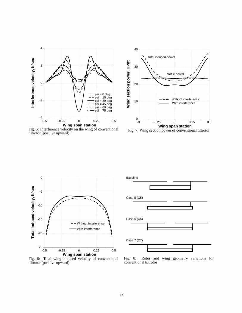
Performance results for a conventional tiltrotor at thedesign cruise of 300 knots at 4000 ft/95 deg F conditionare shown here. The performance was calculatedusing nonuniform inflow with prescribed wake geometry.Figures 5 through 7 show the interference effects on thewing for the baseline configuration. The interferencevelocity from the rotors on the wing is shown in Fig. 5.The interference varies with rotor azimuth and exhibits4/rev variation due to the 4-bladed rotors. The maximuminterference was observed at 30 degree azimuth angle,when the blade tip vortex of the rotor passes thewing quarter chord line. These interference velocitiesreduce total induced velocity along the wing span asshown in Fig. 6. Without interference, the inducedvelocity distribution is same as that of a fixed wing.The interference has a beneficial effect on the wingperformance, reducing wing induced power as shown in
2
Fig. 7. The interference effect did not change wing profilepower. This observation, the reduction of wing drag dueto favorable rotor swirl provided by up-inboard rotatingrotors, was also reported in Refs. [10, 14].
A parametric study was conducted to understand theeffects of design parameters on the performance of theaircraft. Table 3 shows the design parameters investigatedand the rotor and wing geometry variations are illustratedin Fig. 8. First case was the change of rotor rotationaldirection. Second case was the increase of disk loadingto 16.6 lb/ft2 (reduction of rotor blade radius by 5%).To maintain the same blade loading, blade chord wasincreased accordingly. Third case was reduction of cruisetip speed, to increase the propulsive efficiency of therotor. Fourth case was the reduction of wing angle ofattack relative to the fuselage (thus relative to the rotors),to investigate the effect of lift sharing between rotor andwing. Fifth case was the increase of wing span. Tomaintain the same wing loading, wing chord was reducedaccordingly. In this case, the rotors stay at the samewing span as the baseline. Sixth case was the increaseof wing span, same as the fifth case, but the rotorsmove to the wing tips. Seventh case was the increaseof wing span, rotors at the wing tips, and increase ofrotor blade radius (decrease disk loading to 11.9 lb/ft2).To maintain the same blade loading, blade chord wasdecreased accordingly.
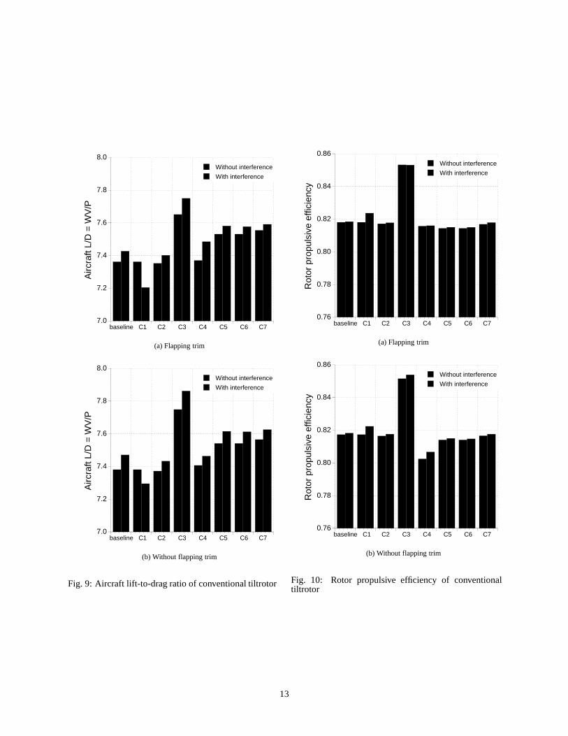
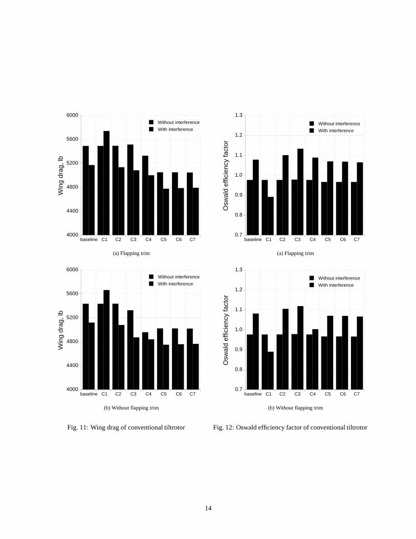
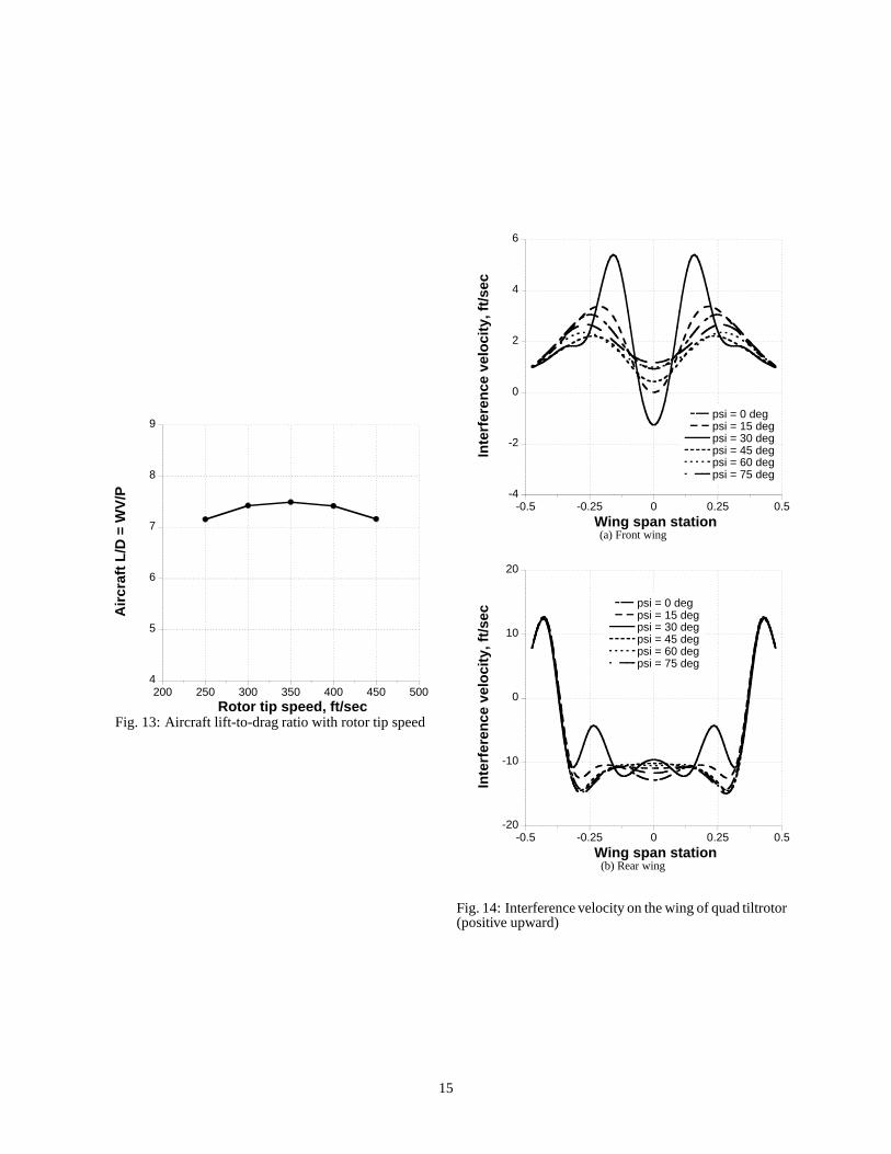
Figure 9 shows the performance results in termsof aircraft lift-to-drag ratio L/D=WV/P, calculatedwithout accessory or other losses, all for the designcruise condition of 300 knots. Rotor/rotor androtor/wing interferences were accounted for using avortex wake model for both the rotor and the wing,and the performance results with interference effectsare compared with those without interference effects.Two trim strategies were used: with flapping trim andwithout flapping trim. The interference effects changedthe aircraft lift-to-drag ratio by up to 2.1% for theparametric variations investigated. The reduction of rotortip speed (C3) increased the aircraft lift-to-drag ratiothe most and the increase of wing span (C5) also has abeneficial effect. The change of rotor rotational direction(C1) decreased the aircraft lift-to-drag ratio significantlyand this effect can only be observed with interferenceincluded in the calculation. The total effect of changingthe rotor direction of rotation was - 3.0% of L/D. Rotordisk loading change (C2, and C7 compared to C6) hasa small influence on the aircraft cruise performance. Ingeneral, flapping trim reduces the aircraft lift-to-dragratio by up to 1.4%.
Figures 10 and 11 show the rotor propulsive efficiencyand wing drag (induced + parasite), respectively. These
are the same calculations as in Fig. 9, except thatindividual performance components are compared. Forthe baseline case, there is a significant reduction of thewing induced drag because of the favorable combinationof the rotor wake and the wing; and a slight increasein rotor propulsive efficiency because of the nonuniformflow field from the wing interference. The change of rotorrotational direction increases rotor propulsive efficiencysomewhat. However, it also increases the wing induceddrag significantly, thus overall performance penalty wasobserved. The reduction of rotor tip speed (C3) increasedthe rotor propulsive efficiency as well as decreased thewing drag. Thus, the most performance improvementwas obtained. The tip speed value of 350 ft/sec wasselected based on the optimum aircraft performance asshown in Fig. 13. The rotor tip speed was varied from250 to 450 ft/sec and the optimum cruise performancewas found at 350 ft/sec tip speed. Further reductions inrotor rotational speed did not improve the aircraft L/D.The reduction of wing angle of attack (C4) changed liftsharing between the rotor and wing; reduced wing liftby about 4000 lb and increased rotor lift by about 4000lb. The reduced wing lift decreased wing induced dragand the increased rotor lift increased rotor induced drag.However, the reduced wing angle of attack also changedwing tip vortex trajectories in a way to increase beneficialinterference effects, thus the rotor propulsive efficiencywas not changed much. The net effect of the reductionof wing angle of attack was a performance improvement.The increase of wing span (C5, and decrease of wingchord) decreased the wing drag (mostly induced drag),but slightly decreased the rotor propulsive efficiency.When the rotor moved to the wing tip (C6) for theincreased wing span (C5), wing drag was reduced dueto increased beneficial interference effects.
Figure 12 shows the Oswald efficiency factor for thewing. Planar wings with the Oswald efficiency equal to1.0 have an elliptical lift distribution and will producethe minimum induced drag for a given wing section andspan. Ideal induced drag (elliptical loading on entire wingsystem) is
Dideal�q � �
L�q � 2 ���
π � span2 � (1)
Thus, Oswald efficiency factor is
e � �Dideal
�q � ���
Dinduced�q �
� �L
�q � 2 ���
π � span2 � � Dinduced�q ��� (2)
The Oswald efficiency factor for the baseline case is0.976 without interference and 1.078 with interference.Those values are very high for a rectangular wing and
3
the 32 aerodynamic panels used in the wing aerodynamiccalculation appear not enough to accurately capturesudden lift drop near the wing tip (aerodynamic panelsize near the wing tip is 2% of the wing span). However,the 32 aerodynamic panels for the wing are consideredenough to investigate the interference effects. Withoutinterference, the Oswald efficiency factor change wasnegligible. The wing drag reduction observed for thecases 5, 6, and 7 was compensated by the wing spanincrease, thus the net wing efficiency was unchanged.The wing efficiency due to interference effects areconsistent with the wing drag results shown in Fig. 11.The interference has a beneficial effect on the wingefficiency for most of the cases investigated, reducingwing induced drag.
Quad Tiltrotor
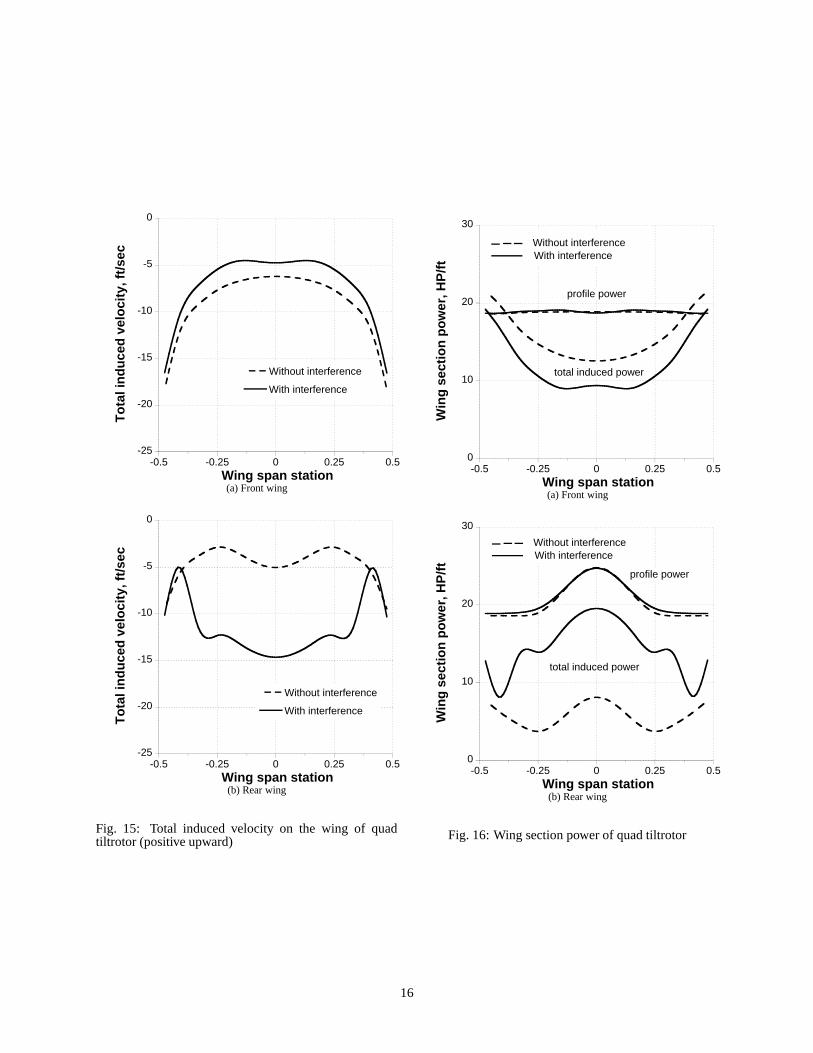
Performance results for a quad tiltrotor configuration areshown here. Figures 14 through 16 show the interferenceeffects on the wing at the design cruise condition of 300knots. The interference velocity from the rotors on thewing is shown in Fig. 14. The interference varies withrotor azimuth and exhibits 4/rev variation due to the 4-bladed rotors. The interference on the front wing issimilar to that of a conventional tiltrotor. The maximuminterference on the front wing was observed at 30 degreeazimuth angle, when the blade tip vortex of the rotorpasses the wing quarter chord line. The interferencevelocity values on the front wing are mostly positive dueto positive interference velocities from the rear wing.The interference on the rear wing is very complicatedbecause several sources affect it. The most dominantinfluence comes from the front wing, determines W-shape distribution. The two humps at � 0.25 originatefrom the two rear rotors. These interference velocitiesreduce total induced velocity along the front wing spanand significantly increase total induced velocity alongthe rear wing span as shown in Fig. 15. Withoutinterference, the induced velocity distribution of the rearrotor is somewhat different from the front wing becauseof the increased chord near mid-span. The interferencehas a beneficial effect on the front wing performance,but degrades the rear wing performance as shown inFig. 16. The interference effect did not change wingprofile power.
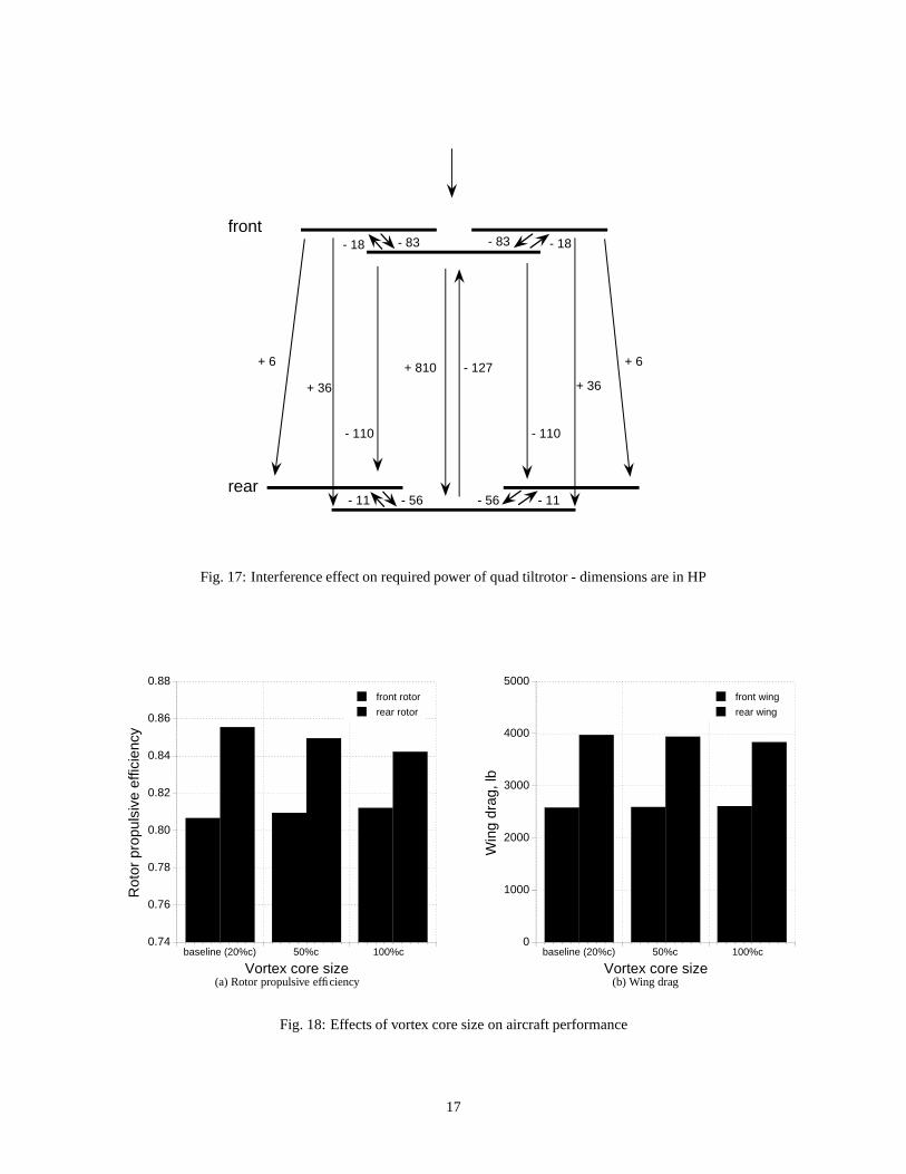
Figure 17 quantifies the interference effect on the aircraftcruise performance, for the baseline configuration. Therequired power changes due to interference are shown.The interference effects between the front rotors and thefront wing and between the rear rotors and the rear wingreduce required power. The front wing has a beneficialinfluence on the rear rotor power. The rear wing alsohas a beneficial influence on the front wing (positive
interference velocity reduced total induced velocity, andthus reduced wing induced power). The front rotorsincrease both rear rotor power and rear wing power,although the effect is not significant. The most dominanteffect is from the front wing to the rear wing. It increasesthe required power of the rear wing by 810 HP (negativeinterference velocity increased total induced velocity, andthus increased wing induced power at most of the wingspan), thus increases the aircraft total required power.
As the vortex core size grows with time (wake age) dueto viscous diffusion, the effects of vortex core size onthe aircraft performance was investigated. It should benoted that the constant vortex core radius of 20% chord(0.2c) was used for all the calculations shown in thispaper. Without knowing an accurate core growth rate,a simple way to examine the effect of core growth isto use larger core size for both rotors and wings whenthe interference velocity is calculated. Figure 18 showsthe effects of vortex core size on the rotor propulsiveefficiency and wing drag. The calculations were madewith two vortex core sizes (0.5%c and 1.0%c) and theresults are compared with the baseline values. As thevortex core size increases, the front rotor propulsiveefficiency increases and the rear wing drag decreases.However, the rear rotor propulsive efficiency decreasesand the front wing drag slightly increases at the sametime. Thus, the total effect of changing the vortex coresize on the aircraft performance is negligible.
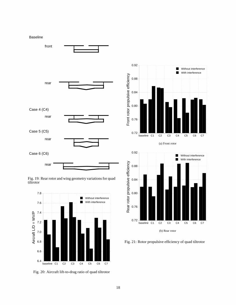
A parametric study was conducted to understand theeffects of design parameters on the performance of theaircraft. Table 4 shows the design parameters investigatedand the rear rotor and wing geometry variations areillustrated in Fig. 19. First case was the change of rotorrotational direction. Second case was reduction of cruisetip speed for all four rotors, to increase the propulsiveefficiency of the rotor. Third case was reduction of bothfront and rear wing chords to obtain wing loading ofW/S = 100 lb/ft2, which is the value for the conventionaltiltrotor. In this case, wing span was maintained sameas the baseline value. Fourth case was rear rotors movedto inboard to make them directly behind the front rotors.Fifth case was rear rotors moved to inboard same as thefourth case, but the rear wing span decreased to matchfront wing span (102.6 ft to 73.3 ft). To maintain the samewing loading, wing chord was increased accordingly.Sixth case was increase of rear wing span by 20% (102.6ft to 123.1 ft) and rear rotors moved to the wing tip.To maintain the same wing loading, wing chord wasdecreased accordingly. Seventh case was rear rotors andwing moved down to the same height as the front rotorsand wings (baseline separation 5.02 ft).
Figure 20 shows the performance results in terms of
4
aircraft lift-to-drag ratio L/D=WV/P, calculated withoutaccessory or other losses, all for the design cruisecondition of 300 knots. The performance was calculatedusing nonuniform inflow with prescribed wake geometry.Rotor/rotor, rotor/wing, and wing/wing interference wasaccounted for using a vortex wake model for both therotor and the wing, and the performance results withinterference effects are compared with those withoutinterference effects. Zero flapping trim was used forall the results for the quad tiltrotor. The interferenceeffects changed the aircraft lift-to-drag ratio by up to7.8% for the parametric variations investigated. Thereduction of rotor tip speed (C2) and increase of wingloading (C3) increased the aircraft lift-to-drag ratio themost and the increase of rear wing span (C6 comparedto C5) also has a beneficial effect. The change of rotorrotational direction (C1) and the move of the rear rotorsand wings to the same height as the front rotors and wing(C7) decreased the aircraft lift-to-drag ratio significantlyand these effects can only be observed with interferenceincluded in the calculation. The move of the front rotorsinboard (C4) has negligible influence on the aircraft lift-to-drag ratio, however the reduction of rear wing span(C5) significantly reduced the aircraft lift-to-drag ratio.
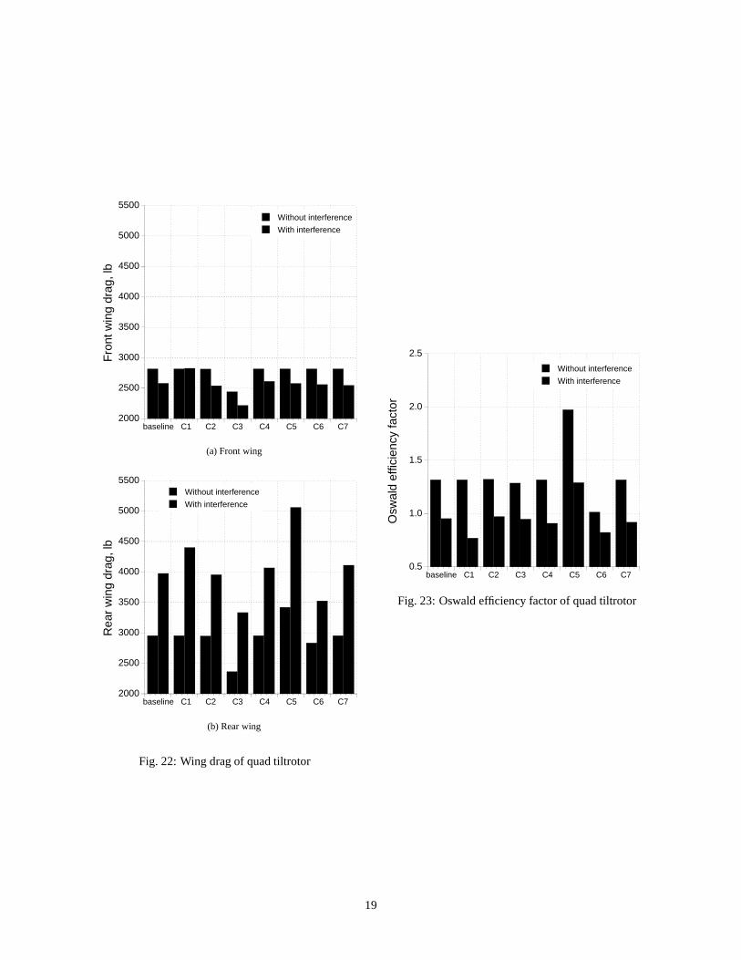
Figures 21 and 22 show the rotor propulsive efficiencyand wing drag, respectively. These are the samecalculations as in Fig. 20, except that individualperformance components are compared. For the baselinecase, there is a reduction of the front wing induceddrag and a significant increase of the rear wing induceddrag because of the nonuniform flow field from therotor and wing interference; and a slight reduction inthe front rotor propulsive efficiency and an increaseof rear rotor propulsive efficiency because of thecombination of the interference and the front rotor thrustdecrease and rear rotor thrust increase. The change ofrotor rotational direction (C1) increases the front rotorpropulsive efficiency. However, it also increases the wingdrag significantly, thus overall performance penalty wasobserved. The reduction of rotor tip speed (C2) increasedthe rotor propulsive efficiency as well as decreased thewing drag. Thus, the most performance improvementwas obtained. The increase of wing span (C6 comparedto C5) decreased the wing drag, but slightly decreased therotor propulsive efficiency.
Without interference effect, the front wing drag valuesdo not change with the parametric variations except forthe wing loading change (C3). With interference effect,the change of rotor rotational direction (C1) increasesthe front wing drag significantly, as for the conventionaltiltrotor. The increase of wing loading (C3, wing chordwas reduced with same span as baseline) significantlyreduced the front wing drag. The significant drag
reduction came from profile drag reduction due to thereduced chord. However, induced drag slightly increased.
The rear wing drag values show significant variationswith the parametric variations and the rear wing dragvalues always increased with the interference effectsfor the parametric variations investigated. The biggestpenalty came from the reduction of the rear wing span(C5) due to the increased induced and interference drag.The biggest benefit came from the increase of wingloading (C3) and the increase of the rear wing span (C6compared to C5). However, the reasons for the wingperformance improvement are different. The increase ofwing loading (C3) resulted in the reduction of profiledrag, but the the increase of the rear wing span (C5)resulted in the reduction of induced and interference drag.
Figure 23 shows the Oswald efficiency factor for theentire wing. Although each wing has its own efficiencyfactor, comparison of the entire wing efficiency wasconsidered more valuable for the design parametric study.Thus, the Oswald efficiency factor definition used in theplot is same as Eqn. (2). However, total wing lift (Ltotal= Lfront + Lrear), and total wing induced drag valueswere used rather than individual wing lift and drag values,but the longer wing span, which is rear wing span for theparametric variations investigated here, was used. Withthis definition of e, the ideal efficiency is e = 1.0 if thetandem wings are in the same plane, but greater than 1.0with vertical separation of the wings. The cases withoutinterference exclude the wing/wing interference as wellas the wing/rotor and rotor/wing interference; using thisdefinition of efficiency, two independent wings each withelliptical loading would give
e � 4���
1 ��spanrear
�spanfront � 2 � (3)
Without interference, the Oswald efficiency factor changewas negligible except for C5 and C6, where rear wingspan decreased and increased, respectively. Although asignificant wing drag change was observed for the C3,the Oswald efficiency factor change is negligible becausethe wing drag change came from profile drag reduction.The Oswald efficiency factor is almost 2.0 for the C5,which is similar to a bi-plane with two wings separated.The interference has an unfavorable effect on the wingefficiency for all the cases investigated.
Conclusions
A performance and design investigation was conducedfor 146,600-lb conventional and quad tiltrotors, whichare to cruise at 300 knots at 4000 ft/95 deg F condition.The aerodynamic interference effects were included in
5
the comprehensive calculations to better understand thephysics and to quantify the effects on the aircraft design.
From this study the following conclusions were obtained:
Conventional tiltrotor
1. Interference effects improves the aircraft lift-to-drag ratio of the baseline conventional tiltrotor.The interference velocities reduce total inducedvelocity along the wing span, and thus reduce winginduced power. The interference effect has verysmall influence on wing profile power and rotorpropulsive efficiency.
2. The reduction of rotor tip speed increased theaircraft lift-to-drag ratio the most among the designparameters investigated and the increase of wingspan also has a beneficial effect on the aircraftperformance.
3. The change of rotor rotational direction decreasedthe aircraft lift-to-drag ratio significantly and thiseffect can only be observed with interferenceincluded in the calculation.
Quad tiltrotor
1. Interference effects degrade the aircraftperformance of the baseline quad tiltrotor.The beneficial interferences occur between thefront rotors and the front wing and between therear rotors and the rear wing and from the frontwing to the rear rotors and the rear wing to frontwing. The unfavorable interferences occur fromfront rotors to the rear rotors and rear wing,from the front wing to the rear wing. The mostdominant effect is from the front wing to the rearwing and it increases the rear wing total inducedpower significantly and thus decrease the aircraftlift-to-drag ratio.
2. The reduction of rotor tip speed and increase ofwing loading increased the aircraft lift-to-drag ratiothe most among the design parameters investigatedand the increase of rear wing span also has afavorable effect on the aircraft performance.
3. The change of rotor rotational direction decreasedthe aircraft lift-to-drag ratio significantly and thiseffect can only be observed with interferenceincluded in the calculation.
References
[1] Johnson, W., Yamauchi, G. K., and Watts, M. E.,“Design and Technology Requirements for CivilHeavy Lift Rotorcraft,” Proceedings of the AmericanHelicopter Society Vertical Lift Aircraft DesignConference, San Francisco, CA, January 2006.
[2] Felker, F. F., Maisel, M. D., and Betzina, M. D.,“Full-scale Tilt-Rotor Hover Performance,” Journalof the American Helicopter Society, Vol. 31, No. 2,April 1986.
[3] Felker, F. F., and Light, J. S, “AerodynamicInteractions Between a Rotor and Wing in Hover,”Journal of the American Helicopter Society, Vol. 33,No. 2, April 1988.
[4] Wood, T. L., and Peryea, M. A., “Reductionof Tiltrotor Download,” Journal of the AmericanHelicopter Society, Vol. 40, No. 3, July 1995.
[5] Snyder, D., “The Quad Tiltrotor: Its Beginning andEvolution,” Proceedings of the American HelicopterSociety 56th Annual Forum, Virginia Beach, VA,2000.
[6] Radhakrishnan, A., and Schmitz, F. H., “AnExperimental Investigation of a Quad Tilt Rotor InGround Effect,” Proceedings of the 21st AppliedAerodynamics Conference, Orlando, FL, June 2003.
[7] Radhakrishnan, A., and Schmitz, F. H., “QuadTilt Rotor Download and Power Measurements inGround Effect,” Proceedings of the 24th AppliedAerodynamics Conference, San Francisco, CA, June2006.
[8] Gupta, V., and Baeder, J. D., “Quad TiltrotorAerodynamics in Ground Effect,” Proceedings of theAmerican Helicopter Society 58th Annual Forum,Montreal, Canada, June 2002.
[9] Gupta, V., and Baeder, J. D., “Investigation ofQuad Tiltrotor Aerodynamics in Forward FlightUsing CFD,” Proceedings of the 20th AppliedAerodynamics Conference, St. Louis, MO, June2002.
[10] McVeigh, M. A., Grauer, W. K., and Paisley, D. J.,“Rotor/Airframe Interactions on Tiltrotor Aircraft,”Journal of the American Helicopter Society, Vol. 35,No. 3, July 1990.
[11] Preston, J., and Peyran, R., “Linking a Solid-Modeling Capability with a Conceptual RotorcraftSizing Code,” Proceedings of the AmericanHelicopter Society Vertical Lift Aircraft DesignConference, San Francisco, CA, January 2000.
6
[12] Johnson, W., “Technology Drivers in theDevelopment of CAMRAD II,” Proceedings ofthe American Helicopter Society AeromechanicsSpecialist Meeting, San Francisco, CA, January1994.
[13] Johnson, W., “Calculation of Tilt RotorAeroacoustic Model (TRAM DNW) Performance,Airloads, and Structural Loads,” AmericanHelicopter Society Aeromechanics Specialists’Meeting, Atlanta, GA, November 2000.
[14] Drees, J. M., “Prepare for the 21st Century - The1987 Alexander A. Nikolsky Lecture,” Journal of theAmerican Helicopter Society, Vol. 32, No. 3, July1987.
7
Table 1: Characteristics of baseline tiltrotor design
mission GW (lb) 146600cruise speed (kt) 300rotor diameter (ft) 78.88disk loading W/A (lb/ft2) 15CW
�σ (geometric) 0.140
CW�σ (thrust weighted) 0.154
tip speed (ft/sec) 750/626solidity (geometric) 0.0989number blades 4blade chord (75%R, ft) 2.79blade taper ratio 0.7aircraft drag D/q (ft2) 55.0wing loading (lb/ft2) 100wing area (ft2) 1466wing span (ft) 96.4
Table 2: Characteristics of baseline quad tiltrotor design
mission GW (lb) 146600cruise speed (kt) 300rotor diameter (ft) 55.78disk loading W/A (lb/ft2) 15CW
�σ (geometric) 0.140
CW�σ (thrust weighted) 0.154
tip speed (ft/sec) 750/626solidity (geometric) 0.0989number blades 4blade chord (75%R, ft) 1.97blade taper ratio 0.7aircraft drag D/q (ft2) 60.3wing loading (lb/ft2) 67.2front wing area (ft2) 848rear wing area (ft2) 1335front wing span (ft) 73.3rear wing span (ft) 102.6
8
Table 3: Parametric variations of conventional tiltrotor
Case 1 (C1) change of rotor rotational directionCase 2 (C2) increase of disk loading (reduction of rotor blade radius by 5%)Case 3 (C3) reduction of cruise rotor tip speed to 350 ft/secCase 4 (C4) reduction of wing angle of attack by 3 degCase 5 (C5) increase of wing span by 10%Case 6 (C6) increase of wing span by 10% and rotors move to the wing tipCase 7 (C7) increase of wing span by 10% and rotors move to the wing tip and increase of rotor blade radius by 12.2%
Table 4: Parametric variations of quad tiltrotor
Case 1 (C1) change of rotor rotational directionCase 2 (C2) reduction of cruise rotor tip speed to 350 ft/secCase 3 (C3) reduction of wing chord to obtain wing loading of 100 lb/ft2
Case 4 (C4) rear rotors moved to inboard to make them directly behind front rotorsCase 5 (C5) rear rotors moved to inboard and rear wing span decreased to match front wing spanCase 6 (C6) increase of rear wing span by 20% and rear rotors moved to the wing tipCase 7 (C7) rear rotors and wing moved down to the same height as front rotors and wings
9
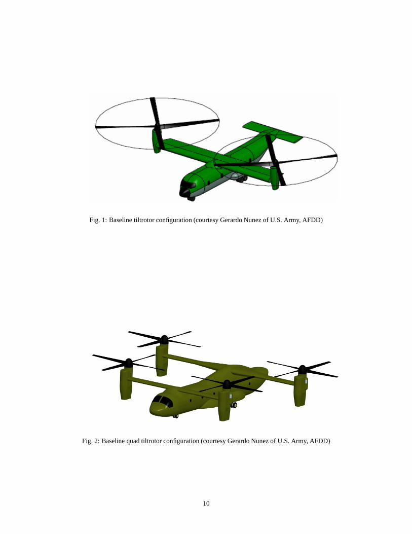
Fig. 1: Baseline tiltrotor configuration (courtesy Gerardo Nunez of U.S. Army, AFDD)
Fig. 2: Baseline quad tiltrotor configuration (courtesy Gerardo Nunez of U.S. Army, AFDD)
10
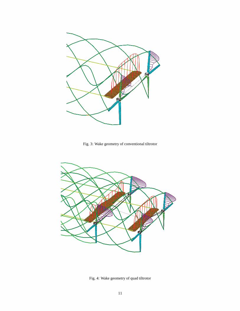
Fig. 3: Wake geometry of conventional tiltrotor
Fig. 4: Wake geometry of quad tiltrotor
11
-4
-2
0
2
4
-0.5 -0.25 0 0.25 0.5
psi = 0 degpsi = 15 degpsi = 30 degpsi = 45 degpsi = 60 degpsi = 75 deg
Inte
rfer
ence
vel
oci
ty, f
t/se
c
Wing span stationFig. 5: Interference velocity on the wing of conventionaltiltrotor (positive upward)
-25
-20
-15
-10
-5
0
-0.5 -0.25 0 0.25 0.5
Without interference
With interference
To
tal i
nd
uce
d v
elo
city
, ft/
sec
Wing span stationFig. 6: Total wing induced velocity of conventionaltiltrotor (positive upward)
0
10
20
30
40
-0.5 -0.25 0 0.25 0.5
Win
g s
ecti
on
po
wer
, HP
/ft
Wing span station
total induced power
profile power
Without interferenceWith interference
Fig. 7: Wing section power of conventional tiltrotor
Baseline
Case 5 (C5)
Case 6 (C6)
Case 7 (C7)
Fig. 8: Rotor and wing geometry variations forconventional tiltrotor
12
7.0
7.2
7.4
7.6
7.8
8.0Without interference
With interference
Airc
raft
L/D
= W
V/P
baseline C1 C2 C3 C4 C5 C6 C7
(a) Flapping trim
7.0
7.2
7.4
7.6
7.8
8.0Without interference
With interference
Airc
raft
L/D
= W
V/P
baseline C1 C2 C3 C4 C5 C6 C7
(b) Without flapping trim
Fig. 9: Aircraft lift-to-drag ratio of conventional tiltrotor
0.76
0.78
0.80
0.82
0.84
0.86Without interference
With interference
Rot
or p
ropu
lsiv
e ef
ficie
ncy
baseline C1 C2 C3 C4 C5 C6 C7
(a) Flapping trim
0.76
0.78
0.80
0.82
0.84
0.86Without interference
With interference
Rot
or p
ropu
lsiv
e ef
ficie
ncy
baseline C1 C2 C3 C4 C5 C6 C7
(b) Without flapping trim
Fig. 10: Rotor propulsive efficiency of conventionaltiltrotor
13
4000
4400
4800
5200
5600
6000Without interference
With interference
Win
g dr
ag, l
b
baseline C1 C2 C3 C4 C5 C6 C7
(a) Flapping trim
4000
4400
4800
5200
5600
6000Without interference
With interference
Win
g dr
ag, l
b
baseline C1 C2 C3 C4 C5 C6 C7
(b) Without flapping trim
Fig. 11: Wing drag of conventional tiltrotor
0.7
0.8
0.9
1.0
1.1
1.2
1.3
Without interference
With interference
Osw
ald
effic
ienc
y fa
ctor
baseline C1 C2 C3 C4 C5 C6 C7
(a) Flapping trim
0.7
0.8
0.9
1.0
1.1
1.2
1.3
Without interference
With interference
Osw
ald
effic
ienc
y fa
ctor
baseline C1 C2 C3 C4 C5 C6 C7
(b) Without flapping trim
Fig. 12: Oswald efficiency factor of conventional tiltrotor
14
4
5
6
7
8
9
200 250 300 350 400 450 500
Air
craf
t L
/D =
WV
/P
Rotor tip speed, ft/secFig. 13: Aircraft lift-to-drag ratio with rotor tip speed
-4
-2
0
2
4
6
-0.5 -0.25 0 0.25 0.5
psi = 0 degpsi = 15 degpsi = 30 degpsi = 45 degpsi = 60 degpsi = 75 deg
Inte
rfer
ence
vel
oci
ty, f
t/se
c
Wing span station(a) Front wing
-20
-10
0
10
20
-0.5 -0.25 0 0.25 0.5
psi = 0 degpsi = 15 degpsi = 30 degpsi = 45 degpsi = 60 degpsi = 75 deg
Inte
rfer
ence
vel
oci
ty, f
t/se
c
Wing span station(b) Rear wing
Fig. 14: Interference velocity on the wing of quad tiltrotor(positive upward)
15
-25
-20
-15
-10
-5
0
-0.5 -0.25 0 0.25 0.5
Without interference
With interference
To
tal i
nd
uce
d v
elo
city
, ft/
sec
Wing span station(a) Front wing
-25
-20
-15
-10
-5
0
-0.5 -0.25 0 0.25 0.5
Without interference
With interference
To
tal i
nd
uce
d v
elo
city
, ft/
sec
Wing span station(b) Rear wing
Fig. 15: Total induced velocity on the wing of quadtiltrotor (positive upward)
0
10
20
30
-0.5 -0.25 0 0.25 0.5
Win
g s
ecti
on
po
wer
, HP
/ft
Wing span station
total induced power
profile power
Without interferenceWith interference
(a) Front wing
0
10
20
30
-0.5 -0.25 0 0.25 0.5
Win
g s
ecti
on
po
wer
, HP
/ft
Wing span station
total induced power
profile power
Without interferenceWith interference
(b) Rear wing
Fig. 16: Wing section power of quad tiltrotor
16
+ 810 - 127
- 110- 110
- 18- 83- 83- 18
- 11- 56- 11 - 56
+ 6+ 6
+ 36 + 36
front
rear
Fig. 17: Interference effect on required power of quad tiltrotor - dimensions are in HP
0.74
0.76
0.78
0.80
0.82
0.84
0.86
0.88front rotor
rear rotor
Rot
or p
ropu
lsiv
e ef
ficie
ncy
baseline (20%c) 50%c 100%c
Vortex core size(a) Rotor propulsive efficiency
0
1000
2000
3000
4000
5000front wing
rear wing
Win
g dr
ag, l
b
baseline (20%c) 50%c 100%c
Vortex core size(b) Wing drag
Fig. 18: Effects of vortex core size on aircraft performance
17
front
rear
rear
Baseline
rear
rear
Case 4 (C4)
Case 5 (C5)
Case 6 (C6)
Fig. 19: Rear rotor and wing geometry variations for quadtiltrotor
6.4
6.6
6.8
7.0
7.2
7.4
7.6
7.8
Without interference
With interference
Airc
raft
L/D
= W
V/P
baseline C1 C2 C3 C4 C5 C6 C7
Fig. 20: Aircraft lift-to-drag ratio of quad tiltrotor
0.72
0.76
0.80
0.84
0.88
0.92Without interference
With interference
Fro
nt r
otor
pro
puls
ive
effic
ienc
y
baseline C1 C2 C3 C4 C5 C6 C7
(a) Front rotor
0.72
0.76
0.80
0.84
0.88
0.92Without interference
With interference
Rea
r ro
tor
prop
ulsi
ve e
ffici
ency
baseline C1 C2 C3 C4 C5 C6 C7
(b) Rear rotor
Fig. 21: Rotor propulsive efficiency of quad tiltrotor
18
2000
2500
3000
3500
4000
4500
5000
5500Without interference
With interference
Fro
nt w
ing
drag
, lb
baseline C1 C2 C3 C4 C5 C6 C7
(a) Front wing
2000
2500
3000
3500
4000
4500
5000
5500Without interference
With interference
Rea
r w
ing
drag
, lb
baseline C1 C2 C3 C4 C5 C6 C7
(b) Rear wing
Fig. 22: Wing drag of quad tiltrotor
0.5
1.0
1.5
2.0
2.5
Without interference
With interference
Osw
ald
effic
ienc
y fa
ctor
baseline C1 C2 C3 C4 C5 C6 C7
Fig. 23: Oswald efficiency factor of quad tiltrotor
19