Embed Size (px)
Citation preview

^ook^o- 18569
LIBRARY RULES
This book maj^Jjg kepi../r;.<fr*TrrrT weeks.
A fine of ivWi'cents will be charged for each day books or
magazines arc kept ovenime.
Two books may be borrowed from the Library at one time.
Any book injured or lost shall be paid for by the person to
whom it is charged.
No member shall transfer his right to use the Library to any
other person.


THE CREEP or STEEL AT HIGHTEMPERATURES


THE CREEP OF STEELAT HIGH TEMPERATURES
/y
BY
rr H: NORTONBabcock & Wilcox Research Fellow,
Afassachiisetts Institute of Technology
First Edition
Second Impression
McGRAW-HILL BOOK COMPANY, Inc.
NEW YORK: 370 SEVENTH AVENUELONDON: 6 & 8 BOUVERIE ST., E. C. 4
1929

Copyright, 1929, by the
McGraw-Hill Book Company, Inc.
PRINTED IN THE UNITED STATES OF AMERICA
THE MAPLE PRESS COMPANY, YORK, PA
PREFACE
This investigation on the creep resistance of steels was
undertaken at the request of the Babcock & Wilcox Co., to
provide engineering data at the higher temperatures. The
work was carried out in the Department of Physics at the
]\Iassachusetts Institute of Technology.
The difficulties in the path of accurately determining the
creep resistance are evidenced by the wide diversity of
values obtained by different experimenters, and there is still
much to be done on the development of research apparatus.
The type of flow occurring in steel is not certain, even
after the subject has been studied by scores of experi-
menters. There is need of more fundamental research.
In the meantime, however, the designer requires engineer-
ing data on a large variety of steels for high temperature
use. It has been attempted here to supply this data
for a considerable number of materials at the higher
temperatures.
The author desires to express his indebtedness to Mr.
J. B. Romer for the metallographic examination of the test
specimens, and to Prof. Albert Sauveur and Dr. R. S.
Williams for examining the manuscript.
F. H. Norton.Cambridge, Mass.
Jioie, 1929.
\&5Q>^


CONTENTSPage
Preface v
CHAPTER 1
Introduction 1
CHAPTER II
The Physical Condition of Steel at High Temperatures 3
CHAPTER III
Creep Test Methods 8
CHAPTER IV
The Babcock & Wilcox Creep Apparatus 11
CHAPTER V
Description of the Steels Tested 20
CHAPTER VI
Results 53
CHAPTER VII
Precision of These Creep Values 66
CHAPTER VIII
Discussion of Results 67
CHAPTER IX
Creep Results of Other Experimenters 71
CHAPTER X
Application of Creep Values to Design 77
CHAPTER XI
Conclusions 79
CHAPTER XII
Bibliography 80
Appendix 87
Index • 89
vii


THE CREEP OF STEEL ATHIGH TEMPERATURES
CHAPTER I
INTRODUCTION
It is only within a relatively few years that the engineer
has realized the importance of the time element in deter-
mining the useful strength of steel at high temperatures.
The working temperatures are ever rising to higher levels
and at any time are limited mainly by the lack of knowl-
edge concerning the properties of steels at high tempera-
tures. It is safe to say that many steam installations are
running today with the superheater tubes at 850°F., andplants are contemplated where the temperature will run
to 900°F. or even 1000°F. In oil stills the metal reaches
900°F. and perhaps lOOO^F., while the temperature in the
mercury boiler runs to 1150°F.
In most structures it is, of course, desirable to increase
the stresses to the highest value compatible with safety.
There must always be, however, a certain reserve in
strength to take care of uncertainties in calculations,
properties of the material and operating conditions. This
is generally called the factor of safety. Our knowledge of
the properties of metals at high temperatures is compara-
tively inexact, and our operating experience under designed
stresses is at present rather limited; so it is necessary to
reduce the stresses in many cases to an unnecessary degree
to secure safety. The various published values of permis-
sible stresses for long life at high temperatures are generally
so discordant that the need for more extensive and precise
data is evident.
1

2 THE CREEP OF STEEL AT HIGH TEMPERATURES
It is the object of this paper to provide the engineer with
data on the safe stresses for various steels, especially at
high temperatures. The methods and results of other
experimenters are briefly reviewed, the Babcock & Wilcox
creep testing apparatus is described, the creep results for
seventeen types of steel at temperatures above 1000°F.
are given, and the significance of the results is discussed.
It is hoped that these results will be of value in the present
and future design of high temperature structures.

CHAPTER II
THE PHYSICAL CONDITION OF STEEL AT HIGHTEMPERATURES
Above red heat, steel has yielding characteristics not
usually associated with it at ordinary temperatures. Wedo not, as yet, have sufficient information to indicate
definitely into which class of soHd or fluid flow hot steel
belongs. It may be either a plastic solid or a viscous
fluid, or combine the properties of both.
A viscous fluid, of which pitch is a good example, has
the flow characteristics shown in curve (a) of Fig. 1. Therate of flow is proportional to the load, even down to the
smallest values, and yet a great resistance may be offered
against loads acting for a short time. This class of
materials has no true elasticity and therefore no yield
point.
A plastic solid, such as wet clay, has flow characteristics
as shown in curve (6) of Fig. 1. Here we have a morecomplicated condition. Until the load reaches a certain
value there is no flow or extension, but after this point is
reached the flow increases regularly in proportion to the
load in excess of this value. It will be noted that the flow
curve does not reach zero at a definite value of load, but
approaches the axis gradually. We do not know the exact
cause of this departure from a straight line at low flow
rates, but it is probably due to the fact that plastic solids
are made up of grains or particles of various sizes and shapes
and some are less resistant to pressure than others.
The distinction between these two types of flow may be
made clearer by a few examples. Glass is considered a very
hard and brittle substance, yet, if a rod or tube be stressed
by laying it horizontally across two supports, it will in the
course of a few years, at room temperature, show a distinct
3

THE CREEP OF STEEL AT HKiH TEMPERATURES
CONDITION OF STEEL AT HIGH TEMPERATURES 5
sag. Sealing wax will do the same thing much more rapidly.
These viscous materials, then, will alter their form with
the very smallest force if time enough is available. Onthe other hand, plastic solids such as a tallow candle or
plasticine may be relatively soft, and yet if not stressed
beyond a certain point will hold their form indefinitely.
Because of the difficulties in accurately measuring the
flow of steel at high temperatures we do not know whether
there is a stress below which no movement occurs. Dicken-
son states ^'The steels which the author has investigated
behave very much like highly viscous fluids well below the
critical range, and cannot be said to have any definite
strength at red heat." He also considers the possibility of
steel creeping even at room temperatures. In fact, flow in
low melting point metals at room temperature has long
been recognized. A number of experimenters have meas-
ured the rate of flow of the softer metals, and it has been
well known that cantilever beams of lead or tin will sag at
room temperatures in a few months. However, little has
been done to determine whether pure metals act as fluids
or solids. Such information, which can be comparatively
easily obtained at room temperature would throw muchlight on the behavior of steel at red heat.
Turning to the mechanism of flow in hot steel we still
have little real information. Steel is not a homogeneous
substance, but is composed of grains more or less separated
by boundary layers. The flow may be due to slippage at
the grain boundaries, to deformation of the grains them-
selves, or perhaps to both. The evidence points to a
primary yielding at the higher temperatures of the grain
boundaries due to the lower softening amorphous material
usually deposited there.
There is a vast amount of work to be done by the physi-
cist in studying the fundamentals of metallic flow. Workshould be carried out on the softer metals at room tempera-
ture where the experimental conditions can be controlled
with great precision. The flow characteristics of a single
crystal would be most interesting. The laws of flow
THE CREEP OF STEEL AT HIGH TEMPERATURES
should then be verified at high temperatures for iron and
and steel. In this way we can greatly simplify our present
CO
to
h'O

CONDITION OF STEEL AT II1(1II TEMPERATURES 7
When annealed steel is stressed slightly beyond its elastic
limit at temperatures below a certain point, the original
proportional limit is raised until the stress is sustained
apparently without further strain. This raising of the
proportional limit can be carried on to a definite load value
beyond which there will be a continuous yielding. This
phenomenon is called strain hardening, and the temperature
below which it occurs, the strain hardening range. This
range varies somewhat with the kind of steel but seldom
extends above 1000°F.; so we are not primarily concerned
with it here. It may be well, however, to point out a few
interesting facts about strain hardening. Work at the
National Physical Laboratory and elsewhere has shown
clearly that metal, strain hardened at a certain temperature,
has the proportional limit permanently raised, and unless a
higher temperature is reached no annealing takes place.
The increase in proportional limit seems to be always
accompanied by an increase in hardness.
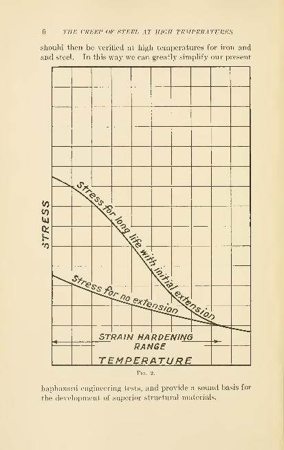
In Fig. 2 are shown typical curves of load plotted against
limiting creep stress and creep stress for no extension.
At the lower temperatures there is a marked difference
between the two curves. As the temperature increases they
converge, until, at the limit of the strain hardening range,
they join and continue together at higher temperatures.
In designing a structure for high temperatures we must
first determine the temperature range in which it is to be
used, and then decide whether a slight initial extension is
permissible or not; if it is, then the allowable stress can run
to the upper curve. If the temperature runs above the
strain hardening range, there is but one set of values to
consider.
It should be emphasized that the frequently used term
''limiting creep stress" is a rather indefinite one. In fact,
we are not sure there is any limiting value. All that can
be accurately stated is that, at a certain load, the rate of
flow is below a certain value, the latter determined by the
precision of the measurement. In this paper the results
are given in hours of life for a one per cent extension.
CHAPTER III
CREEP TEST METHODS
In the earliest methods of testing metals at high tempera-
tures, the specimen was heated in a forge or furnace, and
then quickly placed in a testing machine and pulled. Thetemperature reading was, of course, quite inaccurate, andthe rate of pulling was not considered an important factor.
Perhaps the first accurate work was done at the Water-
town Arsenal in 1888 by Howard. From then on a numberof investigators have studied the strength of metals at
high temperatures. The rate of testing was comparatively
fast, and the temperature was not measured on the speci-
men itself, but usually in a surrounding bath. However,
this work brought out the importance of high temperature
tests on metals.
A number of physicists such as Ewing, Muir and Hop-kinson, studied the characteristics of metals when stressed
above the yield point. Some of the apparatus then used
compares favorably with that used today.
All the earlier experimenters failed to recognize the full
importance of the time element in the flow of steels; so
that their permissible stresses were in most cases too high.
It was pointed out by Atchison in 1919, and later byChevenard, Dickenson, and Lea that steels would contin-
uously extend, at a continuous rate, when loaded consider-
ably below their quick breaking stress. The important
fact shown clearly at this time was that the stresses in a
structure must be low enough to prevent an undue change
in size during its life. This meant that the stress must be
set to give an extremely small extension during the usual
test period of 500 to 1000 hours.
It is believed by French and others that the proportional
limit, as precisely determined in a quick test, approximates
CREEP TEST METHODS 9
in value the limiting creep stress at that temperature, pro-
vided the material is beyond the strain hardening range.
A number of values substantiate this conclusion, but on
the other hand, the work of Clark and White indicates
that the limiting creep stress (if there is a limit) is below
the proportional limit value. We need a large amount of
additional data before we can draw any general conclusions.
In the meantime, it is only safe to base our design on the
results of long time tests.
It may be of interest to describe the more recent methods
of testing in detail; as the refinements in temperature
measurement, temperature control, and extension measure-
ment are carried to a high degree. Some experimenters
maintain the load for a long period of time, and others makea rapid test and determine the proportional limit with
accurate extensometers.
The furnaces are all of the tubular form wound with a
heating coil. The National Physical Laboratory used a
platinum foil winding on a refractory tube, but most of the
others are wound with wire of the nickel-chromium type on
an insulated metal tube. In some cases the winding is
uniform, but French used extra end coils, and Bregousky
and Spring, end coils only, in order to obtain an even
temperature along the specimen. Even with these pre-
cautions there may be a temperature variation along the
specimen of 25° to 50°F. due to conduction along the
holders.
The method used in measuring the extension varies. In
most cases clamps are placed on the top and bottom of the
specimens, and then brought out to a measuring device.
French, Preister and Harder, and Malcolm used two indica-
tor dials. Mochel and McVetty used an optical extensome-
ter of great sensitivity. French, at the Bureau of Standards,
also used an optical extensometer (Tuckerman-Martens)
for the rapid tests. Direct reading micrometer telescopes,
sighted directly on the ends of the specimen, have been used.
This method eliminates any errors in bringing the readings
out of the furnace with rods, but is subject to errors when

10 THE CREEP OF STEEL AT lUail TEMPERATURES
there is any scaling of the specimen. In long time tests,
where the extension readings need not be as precise, the
extension is usually taken on the ends of the holder. It
should be noted that the sensitivity of an extensometer is
not a measure of the obtainable precision. For example,
an instrument can be made to read a millionth of an inch,
but errors caused by temperature variation, differential
expansion, warping, etc., may amount to many times this
value in a long test.
The usual method employed in making a creep test is to load
the specimen at a certain value and maintain this load for a
period of time and measure the rate of extension. Thetest is then repeated at a different load or temperature, and
the extension again determined until a load is found for
each temperature where the steel will just fail to show a
measurable creep. Of course, the longer the time of test
and the more accurate the extension determinations, the
more precise will be the creep value.
In the short time tests the specimen is held very closely
to the desired temperature, then pulled at a uniform rate
and simultaneous readings of load and extension taken.
The proportional limit is usually found graphically. It is
obvious that with more precise readings the deviation from
a straight line can be observed at a lower load than with
less precise ones. We are not at all sure that if we could
obtain results, say one hundred times as precise as at
present, that there would be any limit indicated, any morethan we are sure that there is a stress below which there
is no creep.
CHAPTER IV
THE BABCOCK & WILCOX CREEP APPARATUS
It was desired to test a number of steel specimens simul-
taneously for a long period and at several temperatures.
B&W Creep ApparatusFig. 3.
Therefore, three furnace units, each holding six specimens
were decided upon. The testing unit constructed for this
purpose is shown in Figs. 3 and 4. A standard .505"
11

12 THE CREEP OF STEEL AT HIGH TEMPERATURES
diameter^ test specimen with a 4" gauge length is screwed
into alloy steel holders, and maintained at a given tension
by a simple lever mounted on knife edges.
The holders are so proportioned that they will have a
section decreasing in area as it approaches the cool end,
^ For lower temperatures and high creep resisting steels this diameter is
shghtly reduced.

THE BABCOCK & WILCOX CREEP APPARATUS 18
where higher stresses are permissible, in order to reduce
the heat conduction along the holder to a minimum.The weighing lever has a 10 to 1 ratio, and has suffi-
cient length so that no levehng adjustment is necessary
during the run. This greatly reduces the cost of the
apparatus and makes a very compact and simple
arrangement.
Six specimens are arranged symmetricallj^ inside of the
heating furnace which consists of a 5" iron pipe woundwith asbestos paper and a heating coil. The furnace is
sufficiently long to give a uniform heating effect, and is
carefully insulated to prevent loss of heat. A thermo-
couple is tied tightly to the inner side of each test specimen
so that the individual temperatures can be measured,
although no variation among the six was found in the first
test. As the thermo-couple is on the side of the specimen
away from the furnace wall, it is shielded from the radia-
tion and should read the true temperature of the specimen
wdth precision. Asbestos fiber is packed around the
holders at the top of the furnace to prevent any hot gases
from escaping.
The temperature of the furnace is maintained at a con-
stant value by connecting a thermo-couple, fastened to the
heater winding, to a potentiometer recorder, which operates
a rheostat for regulating the current through the furnace
at the proper value. The controlling couple is placed on
the winding to prevent lag and hunting, and is, of course,
higher than the specimen couples. A set of these control-
lers is shown in Fig. 5. In general the temperature of the
specimens is maintained constant within +5°F. The wires
from the couples on the individual specimens are carried
out to a set of switches and potentiometer as shown in Fig. G.
It is as necessary to keep the room temperature uniform
as it is the specimen temperature, because of the expansion
of the frame work of the testing unit. This temperature
regulation is carried out by circulating the air around the
room by fans and by controlling the amount of air drawnin from the basement corridor. The room temperature
14 THE CREEP OF STEEL AT HIGH TEMPERATURES
Fig. 5.
THE BABCOCK & WILCOX CREEP APPARATUS 15
during the test is constant to within +2°F. The cold
junction of the controller couple is mounted on the cast
iron frame which gives a constant difference between the
frame and the specimens.
16 THE CREEP OF STEEL AT HIGH TEMPERATURES
The extension of the specimens is read directly by dial
gauges, reading to .0001 of an inch. These gauges are
mounted on the top of the apparatus, and are connected by
steel struts to the lever arms directly in line with the
specimens.
In order to prevent oxidation of the specimens a stream
of dry nitrogen is supphed to the bottom of the apparatus
during the test. The complete installation is shown in Fig.
7. It was not found that nitrogen has any appreciable
effect on the steels even after long periods of heating.
The tests are made by bringing the unloaded specimens up
to the desired temperature and then applying a load some-
what below the supposed creep stress. This load is main-
tained steadily for about 400 hours, and a record of the
extension made twice a day. The load is then increased
about 10 per cent and maintained for another 400 hours,
and so on until the rate of creep becomes large. In Fig. 8
is shown the extension readings taken from a test of one of
the steels. It will be noted that the rate of elongation is
approximately constant for each load, and this will be true
until there is a reduction in area, when the rate for a given
load will increase. In these tests, however, the load was
not carried to such high values. At the lower temperatures
some of the specimens elongated for 50 to 100 hours after a
load increase, but due to strain hardening this elongation
ceased if the stress was below the limiting creep value.
The slope of the curves in Fig. 8 are determined graphi-
cally and plotted as rate of elongation against corresponding
load and temperature on log sheets as shown in Figs. 50 to
54. It is clear that in all cases the most representative
curve through the points is a straight line. Whether it
will continue a straight line down to lower rates of creep
or have a bend as indicated by French cannot be determined
without more precise data. This method of plotting is
convenient as it is not difficult to draw a representative
line through a few points and read off the safe load for any
extension rate or life. Even with two values a line can
be drawn with fair precision.
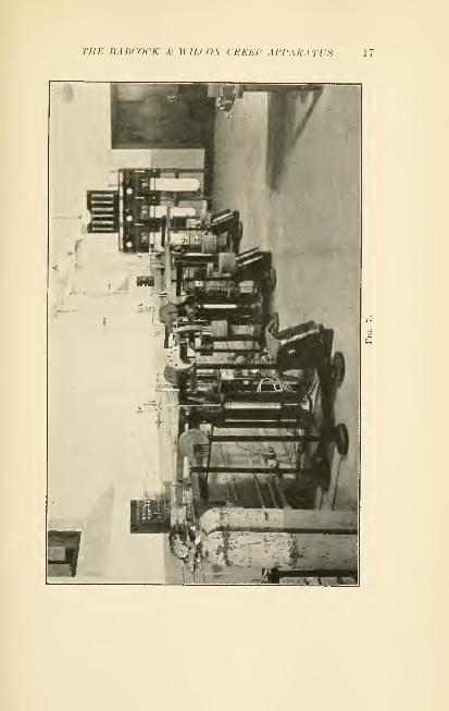
THE BABCOCK & WILCOX CREEP APPARATUS 17

18 THE CREEP OF STEEL AT HIGH TEMPERATURES
Values are taken from these curves representing a life of
100,000 and 10,000 hours with a permissible extension
of one per cent.
120 160 200 240 280 320 360 400
FiQ. 8.
In a number of cases the load on the specimens wasgradually decreased after a definite rate of creep was

THE BABCOCK A- WILCOX CREEP APPARATUS 19
established. In all cases the rate of creep for a given load
was the same when decreasing as when increasing. This
information will allow us in future tests to put on at once
sufficient load to produce a small creep and then reduce
this until the rate of creep is very small. The length of
time required to make a test will be considerably shortened
by using this method. It cannot be used, however, in the
strain hardening range when it is desired to obtain the creep
stress with no initial extension.
CHAPTER V
DESCRIPTION OF THE STEELS TESTED
This section of the report has been prepared by the
metallurgical laboratory of the Babcock & Wilcox Company
at Bayonne, N. J., and gives a complete description of the
original steels as well as the changes occurring during the
test.
In selecting steels for creep analysis, an effort was made
to cover a wide and comprehensive field. The steels
selected fell into three distinct groups. The first, and
as far as creep at high temperatures is concerned, the most
important group, is made up of five steels w^hose composi-
tion is such that they are austenitic at room temperatures.
The second group also contains five steels which differ
from the preceding group in that the amount of alloying
element added, although not sufficient to produce an
austenitic structure at room temperature, is sufficient to
distinctly change many of their characteristics. The third
group consists of a plain carbon steel and six steels in which
the amount of alloying element is just sufficient to bring
about distinct changes in the properties at room and
slightly elevated temperatures.
Austenitic Steels.
In Table I will be found the symbol letter, reference
name and complete chemistry of the five austenitic steels
of the first group.
The complete history of these five steels is not known.
Probably they were hot finished, unannealed bars, although
the last point is uncertain.
These steels are not hardened by heat treatment; on the
other hand, quenching from about 1850°F. develops a
condition of maximum softness and ductility. This is
a characteristic of austenite.
20

DESCRIPTION OF THE STEELS TESTED 21
Table I
kSyniboI Reference NameA 18-8->2 Chrome Nickel Silicon
B 19-G-l Nickel Chrome Silicon
C 25-20-1 Chrome Nickel Silicon
D 20-7-1 >2 Chrome Nickel Silicon
E 18-8-1 > Chrome Nickel SiUcon
B
CarbonI .14%
Silicon .32
Manganese|
.45
Phosphorus .008
Sulphur .014
Nickel 8.23
Chromium 18.15
Tungsten NoneVanadium .13
.14%

22 THE CREEP OF STEEL AT HIGH TEMPERATURES
materials and the specimens after they have been subjected
to the creep tests referred to in the earher chapters.
It has been our experience that a solution of aqua regia
in glycerine develops, to best advantage, the general
structural characteristics of the high chrome alloys. Mur-akami's reagent is resorted, for observing carbides. This
corresponds, in its action, to boiling sodium picrate as
used on plain carbon steels.
STEEL A
18-8-}2 Chrome Nickel Silicon
Per Cent
Carbon 14
Silicon 32
Manganese 45
Nickel 8.23
Chromium 18 . 15
Vanadium 13
Fig. 9.-—Original. 1496-1. 100 X. Etchant—aqua rcgia and glycerine.
The original material is extremely large grained austenite,
indicating that it was finished at a relatively high tempera-
ture. During the tests, a specimen of this steel was heated
to 1200°F. and held at this temperature for a period of

DESCRIPTION OF THE STEELS TESTED 23
Fig. 10.—5900 hours at 12()0°F. 1496-2. 100 X. Etchant—aqua re^ia andglycerine.
Fig. 11.— 1496-.3. 100 X. Etchant—aqua regia and glycerine.
24 THE CREEP OF STEEL AT HIGH TEMPERATURES
5900 hours (under stress) and, as will be noted in Fig. 10,
a distinct change has occurred at the grain boundaries.
Even though the magnification is only 100 diameters, it
can be readily seen that carbides are precipitating at the
boundaries. Further proof of this statement is to be had
by observing Fig. 11, where the magnification is 1000
diameters.
The original material was strictly non magnetic and
etching with Murakami's reagent failed to develop evidence
of carbides. After the long time tests at 1200°F., the
material was distinctly magnetic and Murakami's reagent
showed the presence of considerable carbide. It is evident
that this material is unstable at this temperature.
The instability of this material is not verified by Rock-
well hardness determination. The large grain structure
noted in the original material is reflected in the low hardness
number.Rockwell B
Original value 74 .
After heating at 1200°F 75 .3
STEEL B
19-6-1 Nickel Chrome Silicon
Per Cent
Carbon 14
Silicon 1.09
Manganese 43
Nickel 19.01
Chromium 6.37
Vanadium None
In this steel the amount of nickel and chromium is
reversed, as compared with material A. In addition,
the silicon content is higher. In the original sample,
indications are that considerable carbide was present both
at the boundaries and within the grains. The material is
virtually non magnetic. Murakami's reagent shows a
small amount of carbides at the boundaries in the form of a
chain, as well as some carbide within the grains. The
large masses are not entirely carbides, instead they are
partially a second constituent.
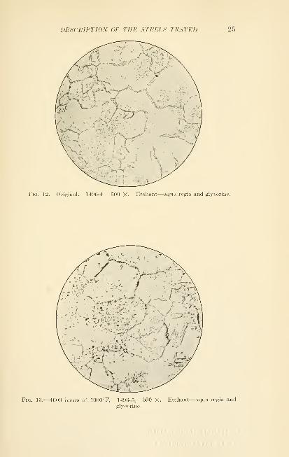
DESCRIPTION OF THE STEELS TESTED 25
Fig. 12.^—Original. 149G-4. 500 X. Etchant—aqua regia and glycerine.
Fig. 13.—4600 hours at 1000°F. 1496-5. 500 X. Etchant—aqua regia andglycerine.

26 THE CREEP OF STEEL AT HIGH TEMPERATURES
Fig. 14.—5500 hours at 1100°F. 1496-6. 500 X. Etchant—aqua regia andglycerine.
Fig. 15.—5900 hours at 1200°F. 1496-7. 500 X. Etchant—aqua regia andglycerine.
DESCRIPTION OF THE STEELS TESTED 27
The effect of heating this material at lOOO^F. for 4600hours has been to develop carbide formation, as can be
observed in Fig. 13. As can be observed in Fig. 14, the
effect of heating at 1100°F. is to increase the second constit-
uent. The effect of heating at 1200°F. for 5900 hours is
to absorb the second constituent that was present in the
original material. As far as can be observed, the carbides
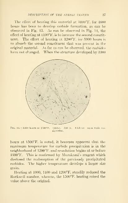
have not changed. "When the structure developed by 3300
Fig. 16.—3.300 hours at loOO°F. 1496-8. 500 X. Etchant—aqua regia andglycerine.
hours at 1500°F. is noted, it becomes apparent that the
maximum temperature for carbide precipitation is in the
neighborhood of 1200°F. and re-solution begins at or before
1500°F. This is confirmed by Murakami's reagent which
disclosed the reabsorption of the previously precipitated
carbides. The higher temperature develops a larger size
grain.
Heating at 1000, 1100 and 1200°F. steadily reduced the
Rockwell number, whereas, the 1500°F. heating raised the
value above the original.

28 THE CREEP OF STEEL AT HIGH TEMPERATURES
Rockwell B
Original value 7!) .
After heating at 1000°F 73 .
3
After heating at 1100°F 72.3
After heating at 1200°F 69.8
After heating at 1500°F 82 .
The absorption of the second constituent, at and below
1200°F., is accompanied by a decrease in hardness. Theabsorption of carbides at 1500°F. is accompanied by an
increase in hardness.
STEEL c
2.5-20-1 Chrome Nickel Silicon
Per Cent
Carbon 12
Silicon 76
Manganese 53
Nickel 19 67
Chromium 24 90
Vanadium 18
In this instance, both nickel and chromium are high, and
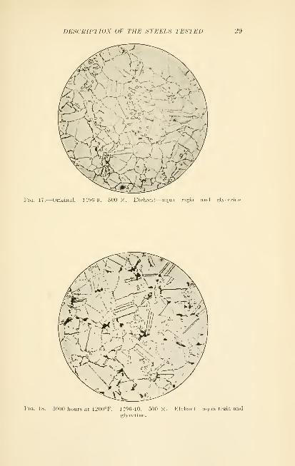
there is considerable silicon present. The grain structure,
in the ''as received" condition, was small, thus indicating a
relatively low finishing temperature. The sample was non
magnetic. When this material was etched with aqua regia,
a number of small particles were observed. Murakami's
reagent developed a number of large carbides within the
grains. After heating for 5900 hours at 1200°F., the etching
characteristics are quite different. Aqua regia develops a
number of black particles, as can be noted in Fig. 18, which
quite likely are carbides. There is also an increase in the
carbides at the boundaries. Evidently this material is
somewhat unstable at 1200°F.
The original material had a relatively high Rockwell
hardness, confirming the belief that the finishing tempera-
ture was low. Long heating at 1200°F. had little effect
on the hardness.
Rockwell B
Original value 93 .
7
After heating at 1200°F 92 .
1
DESCRIPTION OF THE STEELS TESTED 29
Fio. 17.—Original. 14'JG-9. 500 X. Etchant—uquu, regia and glycerine
Fig. 18.—5900 hours at 1200°F. 1496-10. 500 X. Etchant—aqua regia andglycerine.

30 THE CREEP OF STEEL AT HIGH TEMPERATURES
STEEL D
20-7-1H Chrome Nickel Silicon
Per Cent
Carbon 43
Silicon 1.35
Manganese 52
Nickel 6 . 99
Chromium 20 . 16
Vanadium 23
Tungsten 60
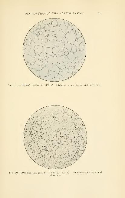
Here we have a steel that differs from the others in that
the chromium and silicon are on the high side, and in
addition, both vanadium and tungsten are present. This
composition will increase the tensile strength and lower the
ductility when tested at room temperatures; however, the
following sections will show that the permissible creep
stress at high temperatures is not improved. The original
material, of small grain size, contained carbide particles
within the grains and only traces at the grain boundaries.
Fig. 19 depicts these conditions.
As a result of heating for 4600 hours at 1000°F. or 5900
hours at 1200°F., the carbide particles have become
smaller and more numerous. The conditions in the two
samples are so similar that only one photomicrograph,
Fig. 20, of the 1200°F. specimen, is shown. The condition
of the carbide particles, coupled with the fact that a slight
degree of magnetism developed, is indicative of the insta-
bility of this material at these temperatures.
The original material was small grained and evidently
finished at a low temperature as is confirmed by the high
Rockwell value.
The specimen heated at 1000°F. showed a lower hardness
than did the original or the 1200°F. specimen.
Rockwell B
Original value 102 .7
After heating at 1000°F 95 .0
After heating at 1200°F 102 .7
DESCRIPTION OF THE STEELS TESTED 31
Fig. 19.—Original. 1496-11. 500 X. Etchant—aqua rcgia and glycciiiif.
Fig. 20.—5900 hours at 1200°F. 1496-12. 500 X. Etchant—aqua regia and
glycerine.
32 THE CREEP OF STEEL AT HIGH TEMPERATURES
STEEL E
18-8->2 Chrome Nickel Silicon
Per Cent
Carbon .09
Silicon 43
Manganese 38
Nickel 8.12
Chromium 18.11
Vanadium None
Chemically, this material is quite similar to material A.
The structure in the ''as received" condition is smaller
grained, thus indicating a lower finishing temperature.
In the ''as received " condition, no indications of magnetism
were observed; heating, however, tended to develop mag-netism. At and below 1200°F., even after long time
heating, the magnetism was quite slight, whereas 3000
hours at 1500°F. produced suflScient alpha iron to give the
sample strong magnetic characteristics.
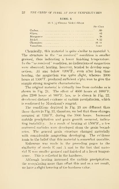
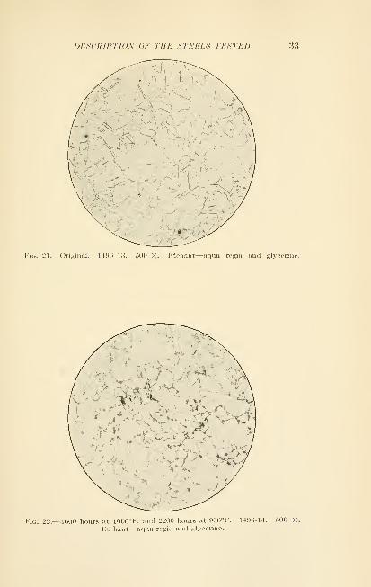
The original material is virtually free from carbides as is
shown in Fig. 21. The effect of 4600 hours at 1000°F.
plus 2200 hours at 900°F. has, as is shown in Fig. 22,
developed distinct evidence of carbide precipitation, which
is confirmed by Murakami's reagent.
The conditions depicted in Fig. 23 are different than
those shown in Fig. 22, therefore, we feel that these changes
occurred at 1200°F. during the 5900 hours. Increased
carbide precipitation and grain growth occurred, indica-
ting instability. As a result of heating at 1500°F., a few
scattered carbides were developed along the grain bound-
aries. The general grain structure changed materially
with considerable magnetism developing. The evidence
leads to the belief that this material is somewhat unstable.
Reference was made in the preceding pages to the
similarity of steels E and A and to the fact that mate-
rial E was smaller grained and finished at a lower temper-
ature. This is reflected in the hardness.
Although heating increased the carbide precipitation,
the re-equiaxing more than offset this and as a net result,
we have a slight lowering of the hardness value.
DESCRIPTION OF THE STEELS TESTED 33
Fiu. 21.—Original. 1496-1.3. 500 X. Etchant—aqua regia and glycerine.
Fio. 22.—-1600 hours at 1000°F. and 2200 hours at 900°F. 1496-14. r,00 X.
Etchant—aqua regia and glycerine.

34 THE CREEP OF STEEL AT HIGH TEMPERATURES
Fig. 23.—5900 hours at 1200°F. plus 1700 hours at 1000°F. 1496-15. 500 X.Etchant—aqua regia and glycerine.
Fig. 24.—.3000 hours at 1500°F. 1496-16. 500 X. Etchant—aqua regia
and glycerine.
DESClill'TIOS OF THE STEELS TESTED 35
Rockwell BOriginal value 92 .
7
After heating at 1000°F 89 .0
After heating at 1200°F 87 .
8
After heating at 1500°!' 87 .
8
The general situation, with respect to the five austenitic
steels, is that variations in chemistry, provided the mate-
rial remains austenitic, have less effect on the physical
properties than do variations of the temperature at which
the material is mechanically worked. On heating, the
above effects are more or less overcome, and by the time the
temperature approaches the transformation point for alpha
iron, the materials of this group, as far as load carrying
ability is concerned, become of about equal value. However,
their stability at high temperature varies materially.
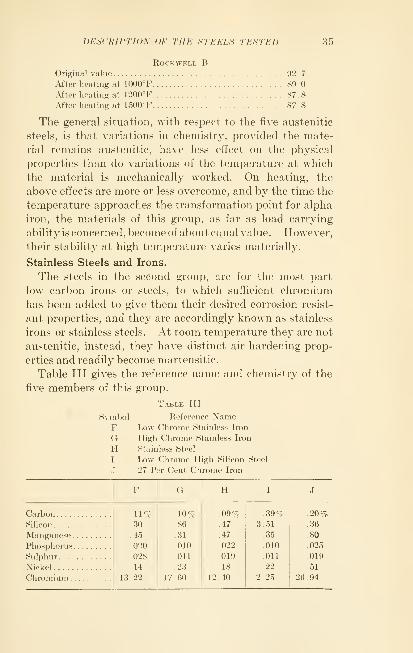
Stainless Steels and Irons.
The steels in the second group, are for the most part
low carbon irons or steels, to which sufficient chromiumhas been added to give them their desired corrosion resist-
ant properties, and they are accordingly known as stainless
irons or stainless steels. At room temperature they are not
austenitic, instead, they have distinct air hardening prop-
erties and readily become martensitic.
Table III gives the reference name and chemistry of the
five members of this group.
Table III
Sym])ol Reference NameF Low Chrome Stainless Iron
G High Chrome Stainless Iron
H Stainless Steel
I Low Chrome High Silicon Steel
J 27 Per Cent Chrome Iron
H
Carbon 11 %Silicon .30
Manganese .45
Phosphorus 020
Sulphur 028
Nickel 14
Chromium 13.22
.10^
.86
.31
.010
Oil
.23
17.00
.09%
.47
.47
.022
.019
.18
1 2 . 40
.39%3.51
.35
.010
.011
.22
2.25
.20%
.36
.80
.025
.019
.51
26.94

36 THE CREEP OF STEEL AT HIGH TEMPERATURES
In the above table, \\e have given the analj'sis of each
individual bar that was used for making the test coupons
for the creep investigation. In practice, it is customaryto regulate a number of these elements between certain
minimum and maximum values. As a result, different
heats will analyze quite differentl}^, and as would be
expected, the physical properties will vary quite mate-
rially. Furthermore, the previous thermal or mechanical
treatment will again alter the physical properties. jVIate-
rial J, for example, has an ultimate tensile strength, in the
fully softened condition, between the limits of 75,000 and
100,000 pounds per square inch. By suitable heat treat-
ment, the ultimate tensile strength of material F can be
raised as high as 210,000 pounds per square inch. In
Table IV we are showing the approximate minimum values
in the fully softened state, of these five materials.
Table IV

DESCRIPTION OF THE STEELS TESTED 37
Fig. 25.—Original. 1496-17. 500 X. Etchant—aqua regia and glycerine.
Fig. 26.—4600 hours at 1000°F. 1496-18. 500 X. Etchant—aqua regia andglycerine.
38 THE CREEP OF STEEL AT HIGH TEMPERATURES
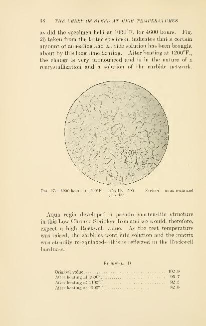
as did the specimen held at 1000°F. for 4600 hours. Fig.
26 taken from the latter specimen, indicates that a certain
amount of annealing and carbide solution has been brought
about by this long time heating. After heating at 1200°F.,
the change is very pronounced and is in the nature of a
recrystallization and a solution of the carbide network.
Fig. 27.—5900 hours at 1200°F. 1496-19. 500glycerine.
Etchant—aqua rogla and
Aqua regia developed a pseudo martensitic structure
in this Low Chrome Stainless Iron and we would, therefore,
expect a high Rockwell value. As the test temperature
was raised, the carbides went into solution and the matrix
was steadily re-equiaxed—this is reflected in the Rockwell
hardness.
Rockwell B
Original value 102 9
After heating at 1000°F 95 .
7
After heating at 1100°F 92 .2
After heating at 1200°F 82 .0

DESCRIPTION OF THE STEELS TESTED 39
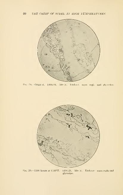
STEEL G
High Chrome Stainless Iron
Per Cent
Carbon 10
SiUcon 86
Manganese 31
Nickel 23
Chromium 17.60
The original condition of this material, as shown in
Fig. 28, is that of a large grained chromiferrous iron
matrix containing many elongated pearlitic or carbide areas
and a few distinct carbides at the boundaries of these
areas. As a result of heating for 4600 hours at 1000°F.
or 5500 hours at 1100°F., these areas break up and manyfree carbides are absorbed. This condition, as found in
the 1100° F. specimen, is well shown by Fig. 29.
The changes brought about by long time heating of
this material lowered the Rockwell hardness.
Rockwell B
Original value 86 .
3
After heating at 1000°F 85 .
7
Mter heating at 1100°F 82.5
40 THE CREEP OF STEEL AT HIGH TEMPERATURES
Fig. 28.—Original. 1496-20. .50n X. lltihant—aqua regia and glycerine.
Fig. 29.—5500 hours at 1100°F. 1496-21. 500 X. Etehant—aqua regia andglycerine.

DESCRIPTION OF THE STEELS TESTED 41
STEEL H
Stainless Steel
Per Cent
Carbon 09
Silicon 47
Manganese 47
Nickel 18
Chromium 12 . 40
Unfortunately none of the original material was avail-
able for microscopic examination. Chemically, this is
very similar to steel F, and there is little doubt but that
under the same conditions of previous mechanical and
thermal treatment, the two structures would be identical.
It is also to be expected that the effects of long time heating
would be to produce structures of the same order. This
is borne out by comparing Fig. 30, w^hich illustrates the
typical structure noted in the specimen of steel H, which
had been heated at 1100°F. for 5500 hours, with Figs. 26
and 27, which show the typical structures of steel F after
similar heating. Higher temperature tends to develop
larger grains and almost complete solution of the carbides.
This is to be noted in Fig. 31, which represents the struc-
ture present in the specimen heated at 1350°F. for 4300
hours.
The same softening was noted in this material as in
material F.
Rockwell B
Original value
After heating at 1100°F 92 .
7
After heating at 1350°F 71 .
5

42 THE CREEP OF STEEL AT HIGH TEMPERATURES
^-
k>^ r
-»i,-A;\..
Fig. 30.—5500 hours at 1100°F. 1496-22. 500 X. Etchant—aqua regia andglycerine.
Fig. 31.—4300 hours at 1350°r. 1496-23. 500 X. Etchant—aqua regia and
glycerine.

DESCRIPTIOX OF THE STEELS TESTED 43
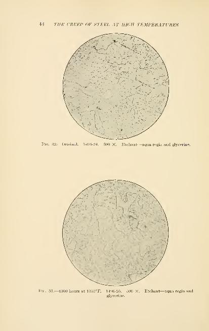
STEEL I
Low Chrome High SiHcoii Steel
Per Cent
Carbon 39
Silicon 3.51
Manganese 35
Nickel 22
Chromium 2 . 25
The presence of 3.5 per cent silicon, with only a little
over 2 per cent of chromium, places this material in a
somewhat different class from the other members of this
group, and judging from Figs. 32 and 33, this material is
quite stable.
Specimens of this material, after 4600 hours at 1000°,
5500 hours at 1100°, and 4000 hours at 1200°F. respec-
tively, were examined and no observable change was noted
in them. In a fourth specimen, after 4300 hours at
1350°r., there is a slight indication of a small change, as
can be noted in Fig. 33. All of these samples show innum-erable small spheroidal carbide particles at the boundaries,
as well as within the grains.
As noted, this material was not affected by heating
and the changes in the Rockwell hardness are corre-
spondingly small.
Rockwell B
Original value 98 .
7
After heating at 1000°F 98 .3
After heating at 1100°F 98.2
After heating at 1350°F 96 .
7
44 THE CREEP OF STEEL AT IIKill TEMPERATURES
Fig. 32.—Original. 1496-24. 500 X. Etchant—aqua regia and glycerine.
Fig. 33.—4300 hours at 1350°F. 1496-25. 500 X. Etchant—aqua regia andglycerine.
DESCRIPTION OF THE STEELS TESTED 45
STEEL J
27 Per Cent Chrome Iron
Per Cent
Carbon 20
Silicon 36
Manganese 80
Nickel ; 51
Chromium 26 . 94
The large amount of chromium present in this material
has such a marked effect on the transformation point
that the gamma phase is completely eliminated. Onheating, this material passes directly from alpha to delta
iron.
We do not have any of the original material, and there-
fore we are unable to state whether the black masses
noted after 4000 hours at 1200°F. were precipitated bythis heating or whether they were in the material originally
and only partly redissolved. Fig. 34 illustrates this
condition at 100 diameters, and Fig. 35 illustrates the
detail of the black particles when viewed at 1000 diameters.
Heating this material for 4300 hours at 1350°F. brings
about an entirely different condition. The black masses
have entirely disappeared, thus indicating that they were
present in the original material. In place of these masses,
we find a number of rather thin elongated envelopes
which probably represent small pools of austenite formed
around carbide particles where the carbon content is suffi-
ciently high to permit of such a condition. This would indi-
cate that they are not dissolved, instead, they have simply
changed their characteristics so that they etch differently.
Murakami's reagent shows uniform carbide distribution
throughout all specimens.
On heating this material at 1500°F., we find that the
black masses, as well as the envelopes, have completely
disappeared and the matrix is now a uniform polyhedral
grain, with the carbides uniformly dispersed as in the
other specimens. As far as can be noted, no change has
occurred in the carbides in any of these samples.

46 THE CREEP OF STEEL AT HIGH TEMPERATURES
Fig. 34.—4000 hours at 1200°F. 1496-26. 100 X. Etchant—aqua regia andglycerine.
Fig. 35.—4000 hours at 1200°F. 1496-27. 1000 X. Etchant—aqua regia
and glycerine.

DESCRIPTION OF THE STEELS TESTED 47
Fiu. 3(j.—4300 hours at 1350°F. 1496-28. 500 X. Etchant—aqua rcgia and
glycerine.
Fig. 37.—3000 hours at 1500°F. 1496-29. 500 X. Etchant—aqua regia andglycerine.

48 THE CREEP OF STEEL AT HIGH TEMPERATURES
The disappearance of the black masses is accompanied
by a lowering of the hardness value, and as the grains
are re-equiaxed, this value falls off a few more points.
Rockwell B
Original value
After heating at 1200°F 95 .5
After heating at 1350°F 88.3
After heating at 1500°F 86 .8
Carbon and Alloy Steels.
The essential character of all the members of the third
group is that they are pearlitic when in the annealed
condition. This is due to the fact that the amount of
alloying elements and carbon are too low to sufficiently
change the temperature or rate of the transformation and,
therefore, the carbon has an opportunity to become
entirely pearlitic on slow cooling.
From the data included in Table V it can be noted
that the seven steels making up this group cover a wide
range of commercial pearlitic steels.
Table V
Symbol Reference NameK . 45 Per Cent Carbon Steel
L 3.5 Per Cent Nickel Steel
M Chrome Nickel Steel
N Chrome Vanadium Steel
O .75 Per Cent Tungsten Steel
P Special Pearlitic Steel
Q 2 Per Cent Tungsten Steel

DESCRIPTION OF THE STEELS TESTED 49
All of these materials were made by the acid open
hearth process and were annealed by heating above the
upper critical point followed by furnace cooling, and it
was in this condition that they were subjected to the
creep tests. The physical properties of these seven steels
vary in the annealed condition. In the following table
will be found the values obtained on a standard .505" X 2"
gauge length coupon made from each bar of the original
material.
Table VI
Symbol
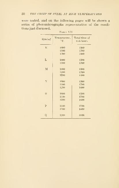
50 THE CREEP OF STEEL AT HIGH TEMPERATURES
were tested, and on the following pages will be shown a
series of photomicrographs representative of the condi-
tions just discussed.
Table VII
Symbol

DESCRIFTION OF THE STEELS TESTED
Steel K
51
Fiu. 38.-—Original. 1496-30. 500 X. Etchuut 4 per cent nital.
Fig. 39.— 1700 hours at 1100°F. 1496-31. 500 X. Etchant 4 per cent nital.
52 THE CREEP OF STEEL AT HIGH TEMPERATURES
Steel L
.^'- ' f7-
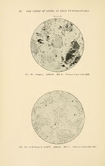
Fig. 40.—Original. 1496-32. 500 X. Etchant 4 per cent nital.
Fig. 41.—1700 hours at 1100°F. 1496-33. 500 X. Etchant 4 per cent nital.
DESCRIPTION OF THE STEELS TESTED
Steel M
53
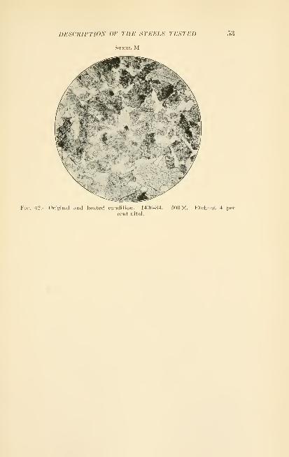
Fk;. 42.—Original and heated condition. 1496-34. 500 X. Etchant 4 per
cent nital.
54 THE CREEP OF STEEL AT HIGH TEMPERATURES
Steel N
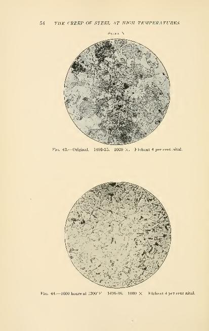
Fig. 43.—Original. 1496-35. 1000 X. Etchant 4 per cent nital.
Fig, 44.—1600 hours at 1200°F 1490-36. 1000 X Etchant 4 per cent nital.

DESCRIPTION OF THE STEELS TESTED 55
Steel O
Fig. 45.—1700 hours at 11 00°F. 149G-37. 1000 X. Etchant 4 per cent nital.

56 THE CREEP OF STEEL AT HIGH TEMPERATURES
Fig. 46.—Original. 1496-38. 1000 X. Etchant 4 per cent nital.
Fig. 47.--1700 hours at 1100°F. 14<)(i-39. 1000 X. Etchant 4 per cent nital.
DESCRIPTION OF THE STEELS TESTED 57
Steel Q
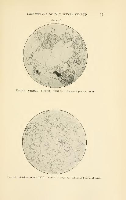
Fig. 48.—Original. 1496-40. 1000 X. Etchant 4 per cent nital.
Fig. 49.—4000 hours at 1200° F. 1490-41. 1000 X. Etchant 4 per cent nital.

CHAPTI]R VI
RESULTS
The rate of flow for the various specimens is shown in
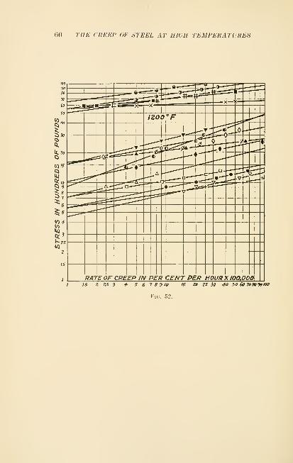
Figs. 50 to 54. As previously stated straight hues seemedto be the best representative curves.
90
80
70
60
50
Co 40
Ci
<0 4
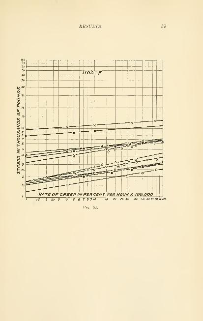
RESULTS 59
50 60 70 8030100
Fig.
(iO THE CREEP OF STEEL AT HIGH TEMPERATURES
RATE OF CREEP IN PER CENT PER HOUR X 100,0001.5 2 25 3 4- 5 6 7 8910 IS 20 ZS 30 40 50 60 708090100
Fig. 52.

RESULTS 61
90
80
10
60
50
40
§

62 THE CREEP OF STEEL AT HIGH TEMPERATURES
I"
?5 6
to
2$

RESULTS 63

64 THE CREEP OF STEEL AT HIGH TEMPERATURES

RESULTS 65
Table VIII. -Creep Stress in Pounds for a Life of 100,000 and 10,000
Hours with 1 Per Cent Elongation
steel

CHAPTER VII
PRECISION OF THESE CREEP VALUES
It is somewhat difficult to give a definite figure for the
precision of the creep results reported here because there
are so many factors contributing to it. These may be
enumerated as follows:
1. Uneven temperature distribution over the specimen.
2. Error in temperature readings.
3. Error in extension measurements.
4. Variation in specimens of same make of steel due
to slight differences in composition, manufacture, etc.
5. Errors in plotting best representative curves.
6. Errors in assuming uniform flow throughout the life.
In several cases duplicate specimens were run and the
agreement was better than 5 per cent. This does not,
however, include any errors listed under (1), (4), and
(6), and possibly under (3). It would seem safe to say
that the creep loads can be relied on to within +25 per
cent, and that the relative values would be somewhatcloser. It would not be advisable, however, to apply
these results too rigorously to design until data is avail-
able from longer tests and from actual installations.
66

CHAPTER VIII
DISCUSSION OF RESULTS
The curves of flow rate in Figs. 50 to 54 show someinteresting facts. While there are not a great manyvalues actually showing a life of more than 10,000 hours,
it would seem reasonable to extend the curves down to a
life of 100,000 hours, because in the cases where values are
available, the curves continue in a straight line. Whetheror not these logarithmic curves wdll continue as straight
lines to the lowest values of load or whether they becomehorizontal at some definite load, we are unable to deter-
mine from these data. However, it is thought that up
to a life of 10,000 hours we have unquestionably a straight
line when plotted on the logarithmic scale. If the straight
line did continue indefinitely, we would have creep even
at the lowest loads, as Dickenson has pointed out, but the
life would be measured in thousands or millions of years.
The straight line on logarithmic paper represents an
exponential function. If y is the flow rate in per cent
per hour, x the stress in lbs. per sq. in. and m and n con-
stants, the relation will be
:
y = mx'^
m is represented by the intercept of the line on the y axis
or the unit flow rate, while n is given by the tangent slope
of the line. The values of n average 5 but range from 3
to 17. This indicates how enormously the rate of creep
runs up with a slight increase in load.
If we were to make tests similar to the ones reported
here, but with a testing time at one load of 4000 hours,
instead of 400 hours, the rate of creep could be measured
with ten times the present precision; and values could be
obtained for much lower rates of creep, allowing the type
67
68 THE CREEP OF STEEL AT HIGH TEMPERATURES
of flow to be known much more accurately. The assump-
tion is made in stating a value for maximum life under a
given load, that the rate of creep remains constant through-
out the life. This assumption is true where the creep
rate is low for a testing time of perhaps as much as 1000 hours,
and it seems reasonable to suppose that the same rate of
creep would still continue for 10,000 or 100,000 hours if
the maximum extension is limited to one per cent, which
is the figure arbitrarily taken here.
It will be noticed that the straight lines in Figs. 50 to
54 have the same general slope. However, a few of the
lines have a somewhat different slope from the average.
For example, the tungsten steels at 1200°F. have a con-
siderably greater slope than the average, whereas one of
the austenitic steels at the same temperature has a com-
paratively low slope. There does not seem to be any
particular significance in the change of slope, and no
consistency can be traced between the different curves.
Some of this change is undoubtedly due to errors in values
and errors in plotting, but this will not account for the
few cases where the change in slope is considerable. Moredata will be required before we can draw any conclusions
concerning this. It seems reasonable that some steels
would have different flow characteristics from others,
and this would be shown by the slope of these curves.
There is little strain hardening shown at temperatures
over 1000°F., although in some cases it occurs. Withthe apparatus used here the extension is not taken directly
on the specimen itself so that we cannot determine the
exact extent of the strain hardening, for the elastic elon-
gation of the apparatus as a whole comes into the extension
readings when the load is changed. That is, these tests
show us the rate of creep, but not the exact amount of
extension.
It will be noticed that the curves in Fig. 55 fall roughly
into three groups: the lowest is carbon and alloy steels;
the second, high chrome stainless steels; and the third
and highest, austenitic steels. It is clearly evident that

DISCU.SSIOX OF RESULTS 6&
at temperatures above 1000°F. the so-called alloy steels
are little superior to plain carbon steel although this
statement of course would not apply to lower temperatures.
The steels of high chromium content show two to three
times the creep resistance of low carbon steel, although
there is a decrease in their resistance with a very high
chromium content. This type of steel probably has notransformation point which may account for the unusual
behavior.
The austenitic steels seem to be approximately alike
in creep resistance, and have values about ten times that
of low carbon steel at these temperatures. The fact is
very striking, however, that the austenitic steels tested
are entirely in a group by themselves in regard to creep
resistance. This is an interesting point, and it is believed
that it has not been brought out before.
At room temperatures austenitic steels are generally
soft and ductile, but have the property of being easily
work hardened. This is the reason why they are so diffi-
cult to machine and why they resist abrasion. At high
temperatures this type of steel offers great resistance to
plastic flow (compared with other steels) which would be
quite unexpected when considering the properties at
room temperature. The reason for this high temperature
rigidity may be due to strain hardening even at the higher
temperatures, or to the fact that the face-centered atomic
structure gives more rigid crystals than the body-centered
structure in the martensitic steels.
If the temperature is raised high enough nearly all
steels will convert to the gamma form. It may be of
interest to see if any of the steels tested here, while not
austenitic at room temperature, are so under the condi-
tions of test. The only specimen of the carbon and alloy
steel group that might approach the transformation point
at 1200°r. is Q with 2 per cent W. It is probable that
these conditions would not produce an austenitic structure,
but it is significant that this steel is the highest of the
group.

70 THE CREEP OF STEEL AT HIGH TEMPERATURES
As chromium raises the critical point, it is doubtful
if any of the stainless steels are austenitic at 1350°F., the
highest test temperature. In fact steel J with 28 per
cent chromium, has creep values distinctly lower than
others of the group, which may be due to the lack of anytransformation temperature. It may be concluded that
the only steels in the austenitic form, at the temperatures
of test, were the stable high chromium nickel type. It
may be mentioned, however, that a high speed steel
tested at the Bureau of Standards had the same high
temperature creep values as a high chromium nickel
austenite. High speed steel would probably be austenitic
at these temperatures.
While more data is necessary before conclusive state-
ments can be made, it is fairly certain that creep resisting
steels must be of the face-centered type (austenitic).
Whether all austenites will give the same creep values,
as indicated here, or whether other types will give somewhat
lower or higher values cannot be decided until more work
has been completed.
The selection of a steel for creep resistance above 1000°F.
(not considering other factors such as corrosion, etc.)
will be guided mainly by the creep value and the cost.
An examination of the curves in Figs. 55 and 56 will lead
at once to the conclusion that alloy steels, at perhaps
twice the cost of carbon steels, are by no means propor-
tionally better. Again, the stainless steels with a creep
resistance of two to three times that of carbon steel cost
ten to fifteen times as much. The austenitic steels (high
chromium and nickel) have a creep resistance at high
temperatures of about ten times that of carbon steel,
and cost little more than the stainless steels. From the
evidence we have here, there is little question but what
the most economical materials to use from the point of
view of creep are carbon and high chromium nickel steel,
and when other factors such as scaling are considered, the
latter is the only practical material.

CHAPTER IX
CREEP RESULTS OF OTHER EXPERIMENTERS
In Table IX are listed a number of steels on which
creep data have been published, and in Figs. 57 to 59 these
data are plotted.
One is struck at once with the great diversity of values
for the same material. This is due for the most part to
differences in method of test and inaccuracy in estimating
a limiting value from too short a testing time. In a num-ber of cases the testing time was so short that a uniform
creep rate had probably not been established at the end
of the test. In others the temperature and extension
measurements have not had the precision of later tests.
For these reasons it is difficult to make any direct compar-
isons. In general the more accurate the experimentation,
the lower will be the estimated ''limiting creep stress."
In the case of carbon steel there are a few values above
1000°F. to compare with the results obtained here. Thevalues reported by French, as well as those of White and
Clark, are in good agreement with ours. The results of
Tapsell and Clenshaw, although at a lower temperature
range, also appear in agreement. Other values are higher.
In the case of other steels there is a fair agreement with
the results of French. The results of other experimenters
are in general higher. In some cases the difference is of
the order of 10 to 1.
In most cases the stresses given are stated to be for an
infinite life, but the precision of testing makes it impossible
to really determine such a value. It is therefore attempted
to give the life for an elongation of 1 per cent which is
really represented by the stresses shown. These times
can only be estimated from the data and methods of each
experimenter and are only approximate.
71

72 THE CREEP OF STEEL AT HIGH TEMPERATURES

CREEP RESULTS OF OTHER EXPERIMENTERS 73
8*
80

74 THE CREEP OF STEEL AT HIGH TEMPERATURES

CREEP RESULTS OF OTHER EXPERIMENTERS 75
Tapsell and CleiLshaw 10,000 to 100,000 h
French 10,000 hns.
Cournot and Sasagawa 5,000 hrs.
Pomp and Dahnien 2 ,000 hrs.
Dickenson 2 ,000 to 10 ,000 hv,
Table IX
No. Composition Authorit^• Reference
Carbon Steels
1

THE CREEP OF STEEL AT HIGH TEMPERATURES
Table IX.
—
{Continued)
Stainless Steels
32
CHAPTER X
APPLICATION OF CREEP VALUES TO DESIGN
When designing a structure for use at the higher tem-
peratures, the usual theories of stress determination based
on the assumption of perfect elasticity do not apply. There
is need of more complete methods of computing stresses
in plastic materials. The chief difference between the
conditions in elastic and plastic materials is that the points
of highest stress concentration are less in the latter due
to an equalization by gradual flow. As far as our present
knowledge goes, stresses determined in the usual mannerwill be on the safe side.
Creep values may be applied to design by selecting a
value corresponding to the desired life and extension.
In view of the variation in creep values, due to the sources
of error previously discussed, it is suggested that two-thirds
of the experimental value be used. As our data becomes
more precise a higher figure can be taken, especially if the
laboratory data can be correlated with service results. Great
care must be taken to determine accurately the actual
maximum temperature of use. In some cases the rate of
flow for a given stress is doubled for a rise of 25°F.
In cases where the metal under stress is hotter on one
side than on the other it is obviously unnecessary to reduce
the stress to the value safe for the hot side, for the cooler
metal is comparatively rigid. Unfortunately, we have
very little information concerning problems of this nature
although they are somewhat analogous to the design of
high temperature refractory walls and crowns, where the
inner face is in a plastic condition and the load is taken
by the rigid outer face.
The selection of a suitable steel for high temperature
requires the consideration of properties other than creep
77

78 THE CREEP OF STEEL AT HIGH TEMPERATURES
resistance. In practically every case the metal must be
resistant to furnace gases and oxidizing conditions. While
certain coatings offer increased resistance to oxidation,
it has been found that, for structures assembled from a
number of parts, an unbroken coating is difficult to main-
tain, which makes it necessary to have a resistant material.
Another essential quality is permanence of structure.
Excessive grain growth or temperature hardening must be
guarded against. Resistance to wear, coefficient of expan-
sion, and ease of working are desirable but less important
properties.
Although there may be some exceptions that we do not
know of, it seems quite clear at present that no previous
treatment will alter the long time properties of steel
above 1000°F. A long heating above this temperature
will efface any previous history. The material, therefore,
can be used in the condition best suited for manufacture.
CHAPTER XI
CONCLUSIONS
The results obtained on steels at temperatures over
1000°r. lead to the following conclusions:
1. The face-centered structure of the austenitic steels
seems to offer a distinctly greater resistance to creep than
the body-centered type.
2. The high chromium, high nickel type of austenitic
steel seems to offer by far the most advantages in regard
to creep resistance, heat resistance, and permanency of
structure.
3. The so-called alloy steels offer little advantage in
creep resistance over carbon steel.
4. The high chromium stainless steels have distinctly
inferior creep resistance as compared with austenitic steels.
5. An increase in chromium content in stainless steel
above 18 per cent seems to decrease the creep resistance.
6. No evidence is found for a cessation of creep as the
load is decreased, and the flow rate seems to decrease
with the load in an exponential manner.
79

CHAPTER XII
BIBLIOGRAPHY
The following bibliography abstracts the more important
articles concerning the flow of metals. There are manyearly articles by physicists dealing with this subject, but
they are not included here because they would not be
of primary interest to the engineer and because the earlier
tests were not continued for a sufficient length of time to
give accurate flow rates.
1921
1. E. L. Dupuy, An experimental investigation of the mechanical properties
of steels at high temperatures. J. Iron and Steel Inst., 104, II, p. 91.
This article discusses rapid tests on steels up to high temperatures, but
contains no creep values.
1922
2. P. Chevenard, Comptes Rendus, 175, p. 486.—This short article gives
creep data on nickel and its alloys at one temperature.
3. J. H. S. Dickenson, The flow of steels at a red heat, Engrn., 114, p. 326,
p. 378.—The above paper considers the creep of steels, giving a descrip-
tion of the apparatus used and data at one stress on a number of steels.
1924
4. F. A. Fahrenwald, Some principles underlying the successful use of
metals at high temperatures. Proc. A.S.T.M., 24, II, p. 310.—The
author discusses the composition and use of metals at high temperatures
as well as the flow of metal under long continued loads. Some data from
service tests are included.
5. H. J. French and W. A. Tucker, Available data on the properties of irons
and steels at various temperatures. Proc. A.S.T.M., 24, II, p. 56.
—
This paper is a compilation of data on the properties of iron and steel
at high temperatures with .some creep values.
6. F. C. Lea, Effect of low and high temperatures on materials. Proc.
Inst. Mech. Engrs., 2, p. 1053.—Very complete tests are made on the
various mechanical properties of steel over a wide range of temperatures.
This is one of the first investigations where the value of long time tests is
reaUzed. The influence of strain hardening is also discussed.
7. V. T. Malcolm, Methods of testing at various temperatures. Proc.
A.S.T.M., 24, II, p. 14.—This is a summary of the history of high
80

BIBLIOGRAPHY 81
temperature testing and considers the apparatus as well as the methodsused. It contains no cr(;ep vaKies.
1925
8. R. W. Bailey, Creep of metals at high temperatures. Eng., 119, p.
518.—This is a discussion of flow in steel and its relation to steampower plant design.
9. J. S. Brown, The influence of the time factor in tensile tests conductedat elevated temperatures. J. Inst. Metals, 34, p. 21, also Engr., 120, p.
297, p. 461.—This paper describes creep tests on several non-ferrous
metals.
10. J. Cournot and K. Sasagawa, Contribution a I'etude de la viscosite des
alliages a temperature elevee. Rev. Met. Mem., 22, p. 753, also ComptesRendus, 181, p. 661.—The flow of several steels is studied at various
temperatures. The specimens are in the form of wires and the duration
of the test is not long, but the extension is measured precisely. Theapparatus and method of test is fully described.
11. H. J. French and W. A. Tucker, Flow in a low carbon steel at various
temperatures. B.S. Tech. Papers, No. 296.—The apparatus and meth-ods used at the Bureau of Standards for creep testing are fully described.
Results are given on a carbon steel and the flow characteristics are
discussed.
12. R. H. Greaves and J. A. Jones, J. Iron and Steel Inst., 112, p. 123.—
A
careful investigation is made on the effect of temperature upon impact
values. A few slow speed tension values are given.
13. T. McLean Jasper, Typical static and fatigue tests on steel at elevated
temperatures. Proc. A.S.T.M., 25, II, p. 27.—This paper discusses
methods of testing but little creep data are given.
14. T. D. Lynch, X. L. Mochel and P. G. McVetty, The tensile properties
of metals at high temperatures. Proc. A.S.T.M., 25, II, p. 5.—Dataon the tensile properties of various materials at temperatures up to
930°F. are collected. Some data on long time tests are given.
15. V. T. Malcolm, Metallurgical developments in the valve and fitting
industry. Journ. A.S.M.E., 47, p. 1141.—The apparatus of a certain
company is described and the importance of creep tests pointed out.
Values are given for two cast steels.
16. A. L. Mellanby and W. Kerr, Trans. N. E. Coast Inst, of Engrs. andShipbuilders, V. 41, P. 243.—The authors bring out clearly the effect
of temperature and time on the useful strength of metals. They also
go fully into the possibilities of steam plant design using the best avail-
able materials.
17. H. F. Moore and T. McLean Jasper, An investigation of the fatigue of
metals. Bull. 152, Eng. Expt. Sta., Univ. of 111.—Fatigue and tensile
data are given for a number of materials up to 1200°F. but includes no
actual creep values.
18. L. W. Spring and J. Kanter, Accuracy in high temperature testing of
materials. Power, 62, p. 325.—Testing methods are described with
particular reference to temperature uniformity in the specimen.
82 THE CREEP OF STEEL AT HKUI TEMPERATURES
19. A. Pomp, strength properties of steel castings at higher temperatures.
Giesserei-Zeitung, 22, 5, p. 124.—Tensile tests on steel castings at
temperatures from 20 to 500°C.
1926
20. R. W. Bailey, Note on the softening of strain hardened metals and its
relation to creep. J. Inst. Metals, 35, p. 27.—The author points out
the relation between rate of softening of work hardening by heat and
the rate of creep.
21. H. J. French, Methods of test in relation to flow in steels at various
temperatures. Proc. A.S.T.M., 26, II, p. 7.—Long time tests are made
on low carbon, stainless and high speed steel, and the data correlated
with short time tests. The limiting creep stress above the strain hard-
ening range is shown to coincide with the proportional limit at the same
temperature.
22. S. H. Inberg and P. D. Sale, Compressive strength and deformation
of structural steel and cast-iron shapes at temperatures up to 950°C.
Proc. A.S.T.M., 26, II, p. 33.—Tests are described on structural steel
and cast-iron shapes at high temperatures. The proportional limit
and the effect of duration of loading is described but no actual creep
data are included.
23. W. Kerr, Failure of metals by creep. Trans. Inst, of Engrs. and Ship-
builders in Scotland, 69, p. 319.—This is a most interesting paper. The
author first reviews carefully the work of the experimenters in the creep
field, and compares and interprets their results. Then he considers
the theory of flow and attempts to set up an equation so that the creep
limit can be found by substituting the values from two short time tests.
The discussion of this paper is also of interest.
24. P. G. McVetty and N. L. Mochel, The tensile properties of stainless
iron and other alloys at elevated temperatures. Trans. A.S.S.T., 11,
No. 1, p. 73.—The tensile properties of annealed stainless iron at
temperatures up to 500°C. are discussed and compared with similar
properties of seven other materials. Requirements of apparatus are
discussed with special reference to the necessity of refinement of stress
and strain measurements.
25. W. Rosenhain, The use of metals at high temperatures. Metallurgist, 2,
Jan. 29, 1926, p. 2.—The appUcation of creep data to design is con-
sidered, with special reference to the allowable stresses in structures
where the temperature varies from one side of the metal to another.
26. H. Shoji, On the plasticity of metals. Science Reports, Tohoku Imp.
Univ., 15, p. 427.—Plastic flow is defined and the flow characteristics
of a number of the softer metals are studied at room temperature.
27. H. Shoji and Y. Mashiyama, On the plasticity of metals at high tempera-
tures. Science Reports, Tohoku Imp. Univ., 15, p. 442.—The flow
characteristics of cadmium, tin and lead are studied up to their melting
point.
28. H. J. TapscU and J. Bradley, The mechanical properties at high tem-
peratures of an alloy of nickel and copper with special reference to creep.

BIBLIOdRAPlIY 83
J. Inst. Metals, 35, p. 75.—Creep and other data are given for a copper-
nickel alloy.
29. G. Welter, Statische Dauerfestigheit von Metallen und Legierungen.
Zeit. Metallkunde, 18, Mar. and Apr. 1926, p. 75 and p. 117.—A large
number of tests are described on the long time strength of metals andalloys at atmospheric temperatures and the results compared with the
ordinary mechanical properties.
30. A. E. White and C. L. Clark, Properties of boiler tubing at elevated
temperatures determined by expansion. Trans. A.S.S.T., 11, No. 1,
p. 73.—The object of this investigation was to determine the safe work-
ing loads for low carbon steel tubes from 900° to 1500°F., but the data
are rather incomplete. It is pointed out that at the higher temperatures
creep occurs much below the proportional limit.
31. Some special steels. Engr., 141, p. 407.—This article discusses two
special steels and their adaptations. Some creep data are included.
32. Furnace Steels. Engineering and Boiler House Review, 39, p. 430.
—
This paper has one creep value.
33. Modern heat resisting steels. Mech. World, 80, p. 59.—A description is
given of recent developments with regard to some heat resisting steels
with some data on creep stress.
34. Safe stresses at high temperatures. Metallurgist, 2, July 30, 1926, p.
104.—An anonymous article gives creep data on a number of steels
tested hv others.
1927
35. I'. W. Bailey, Design at plant for high temperature service. Engrn.,
124, p. 44.—The author believes, and offers proof from the results
of others, that there is no limiting creep stress but that creep continues
at the lowest loads but at an immeasurably small rate. He then applies
this conclusion to design and shows that in many cases a plastic condi-
tion is more favorable than an elastic one.
36. D. Hanson, Some observations on the creep of metals. Metallurgist, 3,
Apr. 20, 1927, p. 54.—Tests are made on aluminum at 490°F. to investi-
gate the theory of creep. It points out that temperature accelerates
the strain-hardening effect.
37. P. Henry, Rercherches experimentales sur les vitisses de deformation des
metaux aux hautes temperatures. Rev. Met. Mem., 24, No. 8, p. 421.
—
The flow in iron and steels is studied in torsion over a temperature range
of 400° to 800°C. Relations are determined between the rate of flow
and the stress, but the time of test is probably not long enough to estab-
lish steady creep flow.
38. V. T. Malcolm and J. Juppenlatz, Investigation of bolt steels. Trans.
A.S.S.T., 11, No. 2, p. 177 —Long time tests are briefly discussed and
some data are given.
39. A. Michel and M. Matte, Variations des proprietes mecaniques des
aciers et alliages avec la temperature. Rev. Met. Mem., 24, No. 4, p.
200.—The previous work on flow in steels is reviewed and some experi-
mental results are given on several steels.

84 THE CREEP OF STEEL AT HIGH TEMPERATURES
40. A. McCance, Properties of steel at high superheat temperatures. Mech.World, 81, p. 434 and p. 435; also Liverpool Eng. Soc, 48, p. 205.—Nooriginal data are given, but the author discusses factors in high tempera-
ture design. It is brought out that previous heat treatment is useless
for steels used at high temperatures because of the progressive anneal-
ing action.
41. A. Pomp and A. Dahmen, Entwicklung eines abgekurtzten prufver-
fahrens zur ermittlung der dauerstandtfestigheit von stahl bei erhohten
tcmperaturen. Mitt. a. d. Kaiser-Wilhelm-Inst. f. Eisenforchung zu
Dussel., IX, No. 3.—This is an extensive article on creep measurements.
The work of others is reviewed with a description of their testing
apparatus. Creep data on several steels are given although the length
of test at one load was only a few hours. The limiting creep stress is
compared with the elastic limit.
42. W. Rosenhain, Behavior of mild steel under prolonged stress at 300°C.
—
A test is made on mild steel at 570°F. of several years duration.
43. F. Schleicher, Tension conditions at flow Hmits. Zeit. AngewandteMathematik U. Mechanik, 6. No. 3, p. 199.—The author surveys
previous hypotheses for flow state and shows lack of accord with actual
conditions. He proposes a new hypothesis which he says is in better
agreement with recent data.
44. L. W. Spring, H. W. Maack and J. Kanter, Testing flow in metals at
various temperatures. Power, 65, p. 205.—The creep test apparatus
used by one investigator is described. The methods of testing and the
theory of flow are discussed.
45. H. J. Tapsell and W. J. Clenshaw, Properties of metals at high tempera-
tures—I, Mechanical properties of Armco Iron, 0.17 per cent carbon
steel, and 0.24 per cent carbon steel with special reference to creep.
Dept. of scientific and industrial research, Engineering Research,
special report No. 1, published under authority of His Majesty's
Stationery Office—Comprehensive tests are described on the mechanical
properties of low carbon steels. The value of creep tests is discussed and
considerable data are given. A good list of references and creep results
by other experimenters are given.
46. H. J. Tapsell and W. C. Clenshaw, Properties of metals at high tempera-
tures—II, Mechanical properties of 0.51 per cent carbon steel and 0.53
per cent carbon cast steel. Dept. of scientific and industrial research,
Engineering Research, special report No. 2, pubUshed under authority
of His Majesty's Stationery Office.—The mechanical properties are
discussed and some creep data are included.
47. A. E. White and C. L. Clark, Properties of ferrous metals at elevated
temperatures as determined by short-time tensile and expansion tests.
A.S.M.E. advance paper for December meeting.—Discusses short-time
tests on high chrome as well as carbon steels.
48. A. Pomp, Das verhalten von stahl bei tiefen und hohen temperaturen.
V. D. I. Zeit., 71, No. 43, p. 1497.—The influence of time on mechanical
tests of steel is discussed for all ranges of temperatures. The hardness
of steel at high temperatures is studied but no creep data are given.

BIBLIOdRAl'HY 85
1928
49. J. L. Cox, Some effects of heat on the physical properties of steel.
Trans. A.S.S.T., 14, p. 225.—This paper describes the phenomenaoccurring in tensile tests of steel with rising temperatures, together
with the appearance and effects of creep. It discusses the application
to design of experimental results and gives a short description of manu-facturing methods.
50. F. B. Foley, On the significance of the proportional hmit at elevated
temperatures. Trans. A.S.S.T., 13, p. 813 and p. 822.—A study to
establish some definite relation between the proportional hmit at roomtemperature and at high temperature. The strain at the proportional
limit and the thermal expansion are used.
51. H. J. French, H. C. Cross, and A. A. Peterson, Creep in five steels at
different temperatures. B.S. Tech. Papers, No. 362.—Creep tests are
made on five types of steel up to 1350°F. with more than the usual
understanding of the difficulties involved. The creep results were
compared with the proportional hmit values on the same steels and the
agreement was good up to temperatures of 1000°F. Thereafter the
creep stress for long Ufe tends to become lower than the proportional
limit.
52. T. McLean Jasper, Strength of steels at elevated temperatures with
particular reference to factor of safety. Power, 67, p. 446.—This
article discusses safety factors and design for high temperature steel
structures. Creep values for two low carbon steels are given.
53. F. Kerber, Ermittlung der dauerstandfestigkeit von stahl bei erhehlen
temperaturen. Zeit. fur Metallkunde, 20, Feb. 1928, p. 45.—The flow of
various metals is described with particular reference to strain hardening
and rate of flow. Most of the tests were run but a few hours. A creep
test apparatus is described.
54. A. Pomp, Das verhalten von stahl gegeniiber dauerbelastungen bei
erhohten temperaturen. Chemische Fabrik (Berlin), No. 5, Feb. 1,
1928, p. 53.—A brief article on the flow of steel at high temperatures is
given.
55. H. J. Tapsell, Properties of materials at high temperatures, 3—Note on
the "creep" of Armco iron. Dept. of scientific and industrial research.
Engineering Research, special report No. 6 pubhshed under authority
of His Majesty's Stationery Office.—The creep of iron is studied particu-
larly at temperatures below 400°F. Strain hardening and temperature
softening are discussed in relation to creep.
56. G. Welter, Ermiidung durch kritische statische dauerbelastiuig. ZeJt.
fiir Metallkunde, 20, Feb. 1928, p. 51.—The flow of several metals is
studied when loaded for long periods at stresses about equal to the yield
point and the elastic limit. Most of the work is done at room tempera-
ture but some interesting results are obtained. The testing apparatus
is described
57. C. L. Clark and A. E. White, The stability of metals at elevated tem-
peratures. Eng. Res. Bull., l^niv. of Michigan.—The authors compare
the creep stress in long time tests with the proportional limit in short

86 THE CREEP OF STEEL AT HIGH TEMPERATURES
tests. At low temperatures the agreement is good, but at high tenipera.-
tures they find no definite limiting creep value. They believe that at a
certain temperature the strength of the crystals is equal to that of the
boundaries. Above this temperature the amorphous boundaries are
the weaker and below it the crystals yield first.
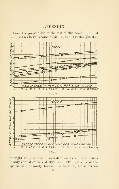
APPENDIX
Since the preparation of the text of this book additional
creep values have become available, and it is thought that
20 2S 30 40 JO iOTOMWm
Fig. go.
30
tf

88 THE CREEP OF STEEL AT HIGH TEMPERATURES
steels with varying carbon content were tested at these twotemperatures. Specimens of steel E in three cases were
re-run at a lower temperature than the initial test in order
to see if the long maintained condition of temperature andstress had influenced their resistance to creep.
The curves of rate of creep are shown in Figures 60 and61. and the results are summarized in the following table:
Table X.—
INDEX
Acid open-hearth process, 49
90 CREEP OF STEEL AT HIGH TEMPERATURE
M
Mechanical work, 21
Metals, pure, 5
Micrometer telescopes, 9
Murakami's reagent, 22, 24, 45
N
Nitrogen, 16
Non-magnetic material, 24
Oxidation of specimens, 16
Oxidizing conditions, 78
Permanency of structure, 79
Photomicrographs, 22, 50
Plastic materials, 77
solid, 3
Potentiometer recorder, 13
Precision, 7, 10, 66
Previous history, 78
Proportional limit, 7, 8, 10
R
Rate of elongation, 16
extension, 10
Reduction in area, 16
Recrystallization, 38
Re-equiaxe, 32, 48
Resistance to wear, 78
Rockwell hardness, 24, 28, 30, 35,
38, 39, 41, 43, 48
Slope, 16, 68
Sodium picrate, 22
Specimen holders, 12
S))eciniens, 11, 13
SpluMoidization, 43, 49
Stability at rooni temperature, 35
Steel, air-hardening properties of, 35
alloy, 20, 69, 75
austenitic, 20, 21, 69, 76, 79
carbon, 20, 70, 75
and alloy, 48, 68
cast, 76
chrome nickel, 49
silicon, 30, 32
vanadium, 49
high speed, 70, 7Q
low chrome, high silicon, 43
original, 20
pearlitic, 48
physical condition at high
temperatures, 3
physical properties, 49
austenitic, 21
stainless, 35, 41, 68, 70, 76
cost, 70
physical properties, 36
Strain hardening, 7, 9, 68
T
Temperature distribution, 66
mercury boiler, 1
oil stills, 1
room, 13
steam installation, 1
Tensile strength, 21, 36
Thermocouple, 13
cold junction, 15
Time element, 8
Transformation point, 69, 70
Safe load, 16
Scaling, 10, 70 Yield point, 21


3Q
Q
I
33
TA473N6 Norton, Frederick Harwood, 1896-
The creep of steel at hightemperaturesy by F« H» Norton. 1st ed.New York [etc.] AicGraw-Hill bookcompany-f inc.y 1929.
vii, 90 p. illus.t diagrs. 24 cm.
18569
-)