Embed Size (px)
Citation preview
1
A Review of Methods to Estimate Creep Damage in Low
Alloy Steel Power Station Steam Pipes
C. Maharaj*, J. P. Dear† and A. Morris‡
*, †Department of Mechanical Engineering, Imperial College London, SW7 2AZ, UK
‡ Technical Head Integrity, E.ON UK, Power Technology, Ratcliffe-on-Soar, Nottingham, NG11
0EE, UK
*[email protected]; †[email protected]; ‡[email protected]
ABSTRACT: For large complex structures such as power stations, refineries and other
processing plants, cost effective operation is essential. With power stations, failures of
components without prior warning can have serious consequences for personnel on site
and be extremely expensive in terms of both losses in generation revenue and repair
costs. The ability to monitor and assess the evolution of damage is critical to
maximising plant availability and to minimise the risk of failures that pose a threat to
personnel safety. This paper relates to the methods used to estimate creep damage in
service aged low alloy steel steam piping. Welds and the extrados of bends in steam
pipes are a particular problem with regards to measuring for the onset and progression
of creep failure. Existing techniques will be discussed with respect to traditional site
based and laboratory testing and assessment. Emerging strain monitoring techniques
will also be described and evaluated that include point-to-point measurement and two-
dimensional mapping of creep strain across the weld zone and other creep susceptible
components of power-station steam piping.
KEY WORDS: creep, welds, high temperature steam pipes, condition monitoring

2
NOMENCLATURE:
AE - Acoustic Emission
API - American Petroleum Institute
ARCMAC - Auto-Reference Creep Management And Control
BS - British Standard
CCD - Charge-Coupled Device
CDM - Continuum Damage Mechanics
CMV - Cr (0.5wt%), Mo (0.5wt%), and V (0.25wt%) Steel
DIC - Digital Image Correlation
DSLR - Digital Single-Lens Reflex
ECR - Extensometer Calibration Rig
FATS - Focused Annular Array Transducer System
FE - Finite-Element
HAZ - Heat Affected Zone
LED - Light-Emitting Diodes
LPA - Linear Phased Array
MPC - Materials Properties Council
NPL - UK National Physical Laboratory
SEM - Scanning Electron Microscope
TOFD - Time Of Flight Diffraction
UT - Ultrasonic Testing
σ - Stress
x - Strain in the x-direction (horizontal)
y - Strain in the y-direction (vertical)
A - Manufactured reference distance on the gauge (3mm)

3
B(t) - Distance between two outer targets on the gauge as a function of time
GL - Installed gauge length (mm) between the weld pins
t - Creep exposure time
T - Temperature
2D - Two-Dimensional
3D - Three-Dimensional
4
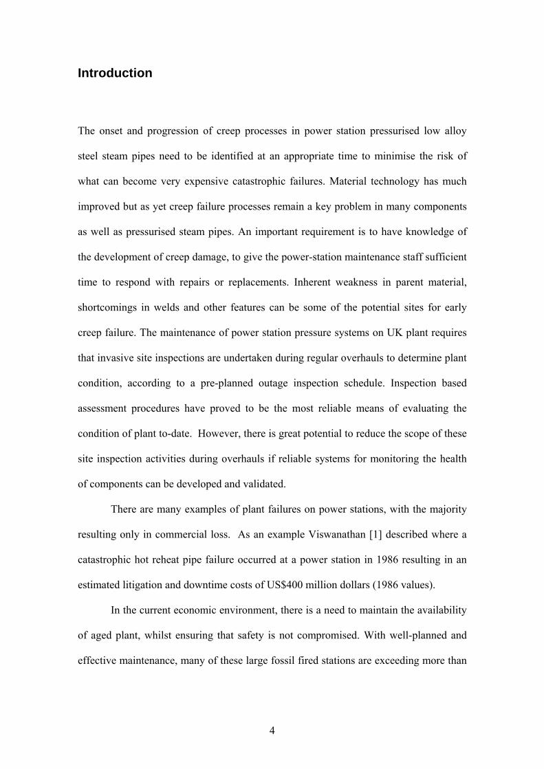
Introduction
The onset and progression of creep processes in power station pressurised low alloy
steel steam pipes need to be identified at an appropriate time to minimise the risk of
what can become very expensive catastrophic failures. Material technology has much
improved but as yet creep failure processes remain a key problem in many components
as well as pressurised steam pipes. An important requirement is to have knowledge of
the development of creep damage, to give the power-station maintenance staff sufficient
time to respond with repairs or replacements. Inherent weakness in parent material,
shortcomings in welds and other features can be some of the potential sites for early
creep failure. The maintenance of power station pressure systems on UK plant requires
that invasive site inspections are undertaken during regular overhauls to determine plant
condition, according to a pre-planned outage inspection schedule. Inspection based
assessment procedures have proved to be the most reliable means of evaluating the
condition of plant to-date. However, there is great potential to reduce the scope of these
site inspection activities during overhauls if reliable systems for monitoring the health
of components can be developed and validated.
There are many examples of plant failures on power stations, with the majority
resulting only in commercial loss. As an example Viswanathan [1] described where a
catastrophic hot reheat pipe failure occurred at a power station in 1986 resulting in an
estimated litigation and downtime costs of US$400 million dollars (1986 values).
In the current economic environment, there is a need to maintain the availability
of aged plant, whilst ensuring that safety is not compromised. With well-planned and
effective maintenance, many of these large fossil fired stations are exceeding more than

5
30 years of service. This is a considerable achievement as these power generation plants
were initially designed for 20 years of service.
In the UK, power stations have operated in a deregulated market for several
years, consequently operational demands are prone to change at relatively short notice
to maximise commercial revenues. Present economics of most aged plant may not allow
for total upgrade of creep susceptible low alloy steel pipes. It is therefore important that
a condition monitoring strategy evolves to ensure present competitiveness and future
survivability of plant. Therefore, the inspection and maintenance requirements must be
re-evaluated and continuously optimised over time. This paper offers insight into the
methods being currently researched and applied to estimate creep in low alloy steel
power station steam pipes. An optimised combination of any of these methods can
become an effective creep condition monitoring strategy.
6
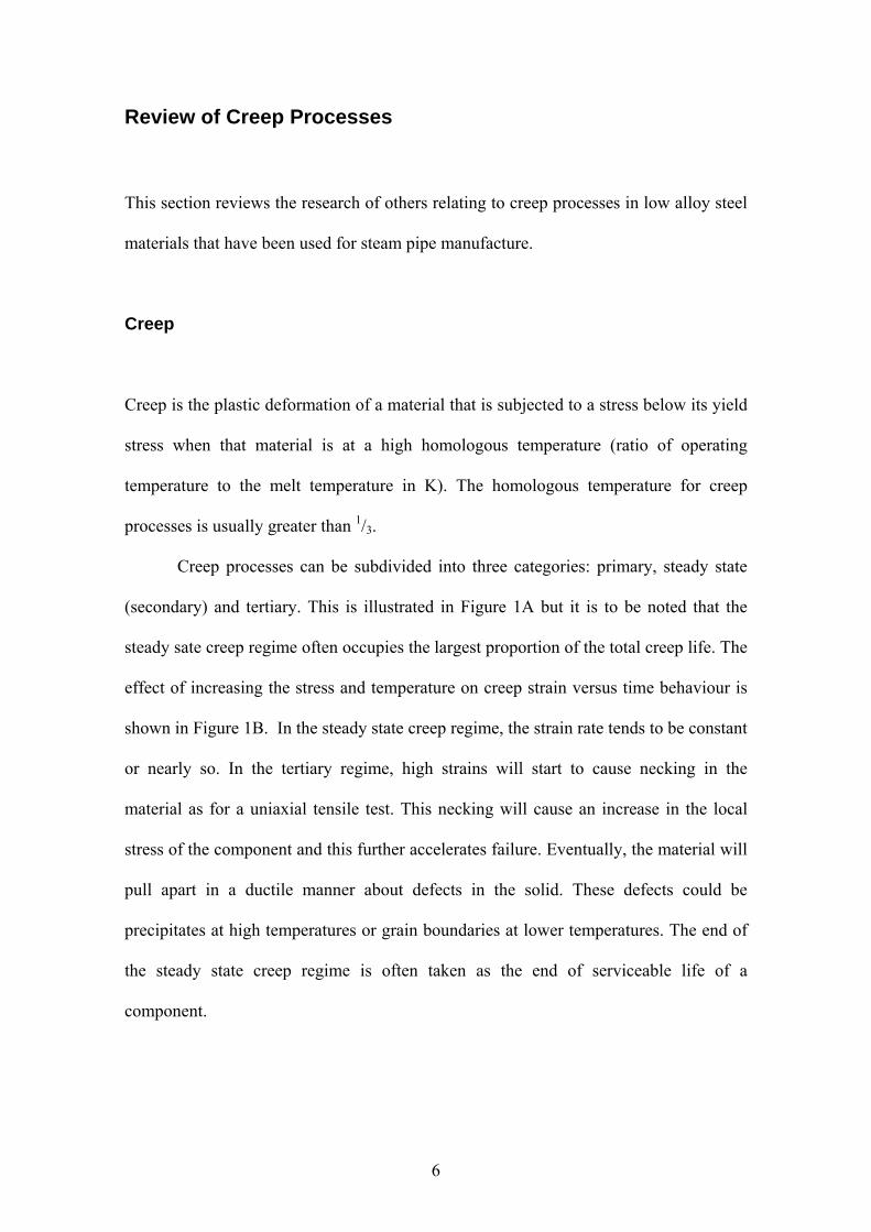
Review of Creep Processes
This section reviews the research of others relating to creep processes in low alloy steel
materials that have been used for steam pipe manufacture.
Creep
Creep is the plastic deformation of a material that is subjected to a stress below its yield
stress when that material is at a high homologous temperature (ratio of operating
temperature to the melt temperature in K). The homologous temperature for creep
processes is usually greater than 1/3.
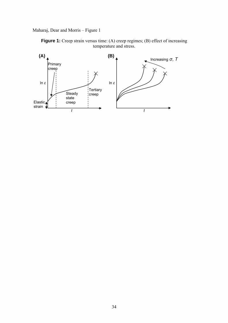
Creep processes can be subdivided into three categories: primary, steady state
(secondary) and tertiary. This is illustrated in Figure 1A but it is to be noted that the
steady sate creep regime often occupies the largest proportion of the total creep life. The
effect of increasing the stress and temperature on creep strain versus time behaviour is
shown in Figure 1B. In the steady state creep regime, the strain rate tends to be constant
or nearly so. In the tertiary regime, high strains will start to cause necking in the
material as for a uniaxial tensile test. This necking will cause an increase in the local
stress of the component and this further accelerates failure. Eventually, the material will
pull apart in a ductile manner about defects in the solid. These defects could be
precipitates at high temperatures or grain boundaries at lower temperatures. The end of
the steady state creep regime is often taken as the end of serviceable life of a
component.
7
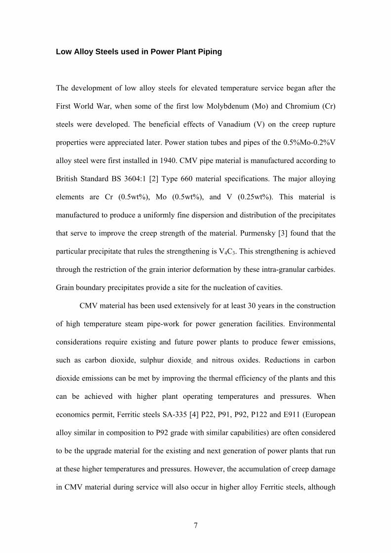
Low Alloy Steels used in Power Plant Piping
The development of low alloy steels for elevated temperature service began after the
First World War, when some of the first low Molybdenum (Mo) and Chromium (Cr)
steels were developed. The beneficial effects of Vanadium (V) on the creep rupture
properties were appreciated later. Power station tubes and pipes of the 0.5%Mo-0.2%V
alloy steel were first installed in 1940. CMV pipe material is manufactured according to
British Standard BS 3604:1 [2] Type 660 material specifications. The major alloying
elements are Cr (0.5wt%), Mo (0.5wt%), and V (0.25wt%). This material is
manufactured to produce a uniformly fine dispersion and distribution of the precipitates
that serve to improve the creep strength of the material. Purmensky [3] found that the
particular precipitate that rules the strengthening is V4C3. This strengthening is achieved
through the restriction of the grain interior deformation by these intra-granular carbides.
Grain boundary precipitates provide a site for the nucleation of cavities.
CMV material has been used extensively for at least 30 years in the construction
of high temperature steam pipe-work for power generation facilities. Environmental
considerations require existing and future power plants to produce fewer emissions,
such as carbon dioxide, sulphur dioxide, and nitrous oxides. Reductions in carbon
dioxide emissions can be met by improving the thermal efficiency of the plants and this
can be achieved with higher plant operating temperatures and pressures. When
economics permit, Ferritic steels SA-335 [4] P22, P91, P92, P122 and E911 (European
alloy similar in composition to P92 grade with similar capabilities) are often considered
to be the upgrade material for the existing and next generation of power plants that run
at these higher temperatures and pressures. However, the accumulation of creep damage
in CMV material during service will also occur in higher alloy Ferritic steels, although
8
the evolution and progression are different. This is discussed further in the Replica
Metallography section.
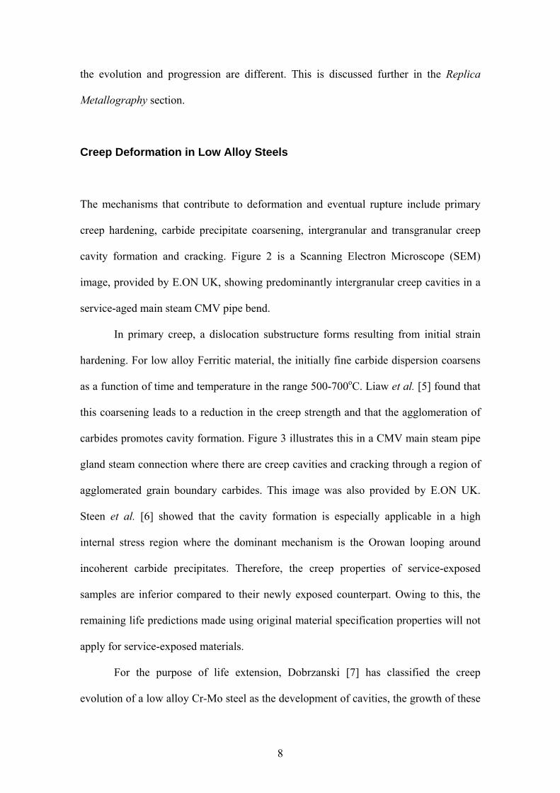
Creep Deformation in Low Alloy Steels
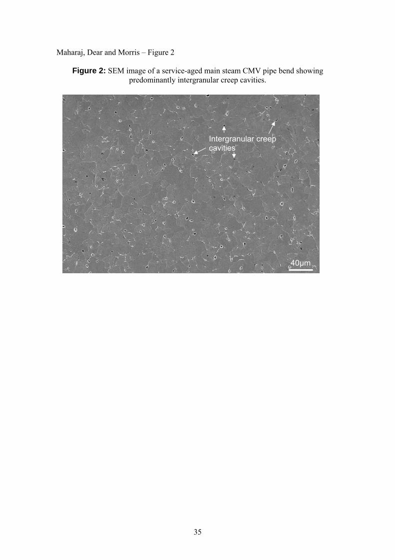
The mechanisms that contribute to deformation and eventual rupture include primary
creep hardening, carbide precipitate coarsening, intergranular and transgranular creep
cavity formation and cracking. Figure 2 is a Scanning Electron Microscope (SEM)
image, provided by E.ON UK, showing predominantly intergranular creep cavities in a
service-aged main steam CMV pipe bend.
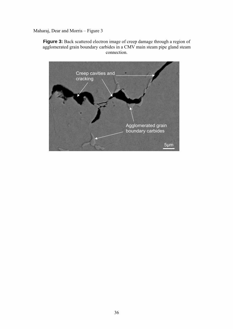
In primary creep, a dislocation substructure forms resulting from initial strain
hardening. For low alloy Ferritic material, the initially fine carbide dispersion coarsens
as a function of time and temperature in the range 500-700oC. Liaw et al. [5] found that
this coarsening leads to a reduction in the creep strength and that the agglomeration of
carbides promotes cavity formation. Figure 3 illustrates this in a CMV main steam pipe
gland steam connection where there are creep cavities and cracking through a region of
agglomerated grain boundary carbides. This image was also provided by E.ON UK.
Steen et al. [6] showed that the cavity formation is especially applicable in a high
internal stress region where the dominant mechanism is the Orowan looping around
incoherent carbide precipitates. Therefore, the creep properties of service-exposed
samples are inferior compared to their newly exposed counterpart. Owing to this, the
remaining life predictions made using original material specification properties will not
apply for service-exposed materials.
For the purpose of life extension, Dobrzanski [7] has classified the creep
evolution of a low alloy Cr-Mo steel as the development of cavities, the growth of these
9
cavities, the formation of micro-cracks and the formation of macro-cracks that lead to
eventual rupture. He also demonstrated that intergranular cavitation cracks were the
dominant factor in service damage of power station boiler components operating in the
creep regime, although some degree of intergranular crevice cracking was observed.
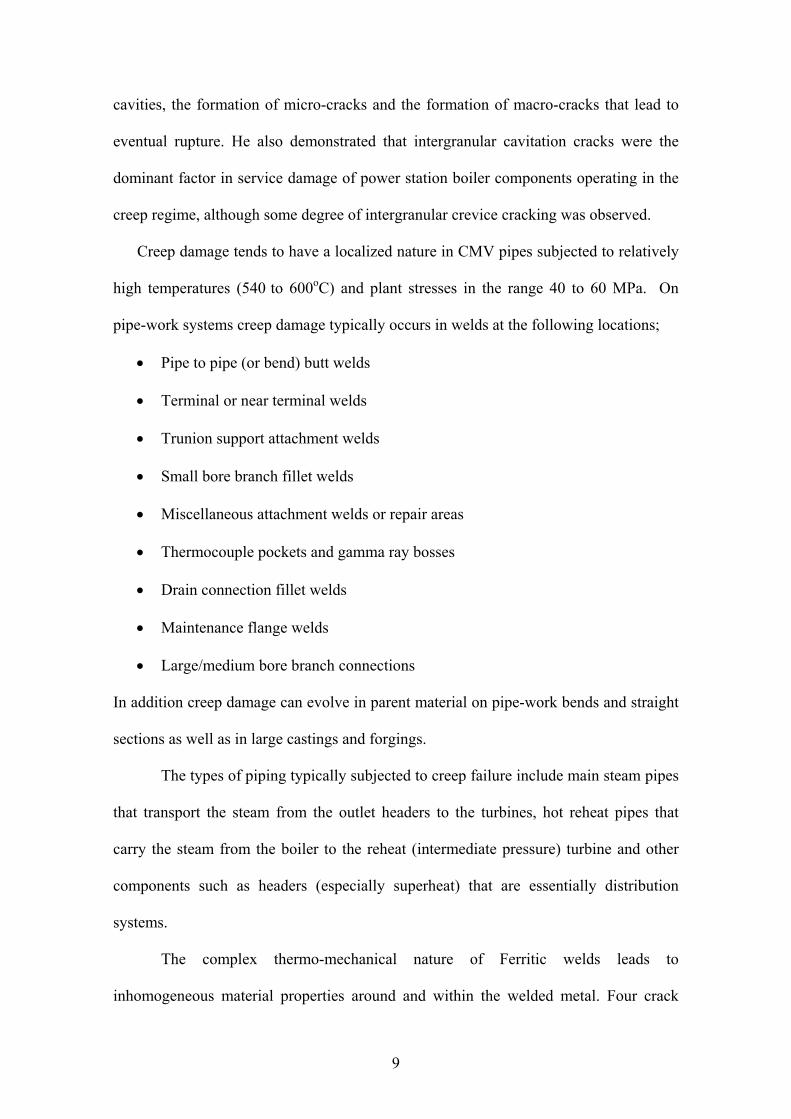
Creep damage tends to have a localized nature in CMV pipes subjected to relatively
high temperatures (540 to 600oC) and plant stresses in the range 40 to 60 MPa. On
pipe-work systems creep damage typically occurs in welds at the following locations;
Pipe to pipe (or bend) butt welds
Terminal or near terminal welds
Trunion support attachment welds
Small bore branch fillet welds
Miscellaneous attachment welds or repair areas
Thermocouple pockets and gamma ray bosses
Drain connection fillet welds
Maintenance flange welds
Large/medium bore branch connections
In addition creep damage can evolve in parent material on pipe-work bends and straight
sections as well as in large castings and forgings.
The types of piping typically subjected to creep failure include main steam pipes
that transport the steam from the outlet headers to the turbines, hot reheat pipes that
carry the steam from the boiler to the reheat (intermediate pressure) turbine and other
components such as headers (especially superheat) that are essentially distribution
systems.
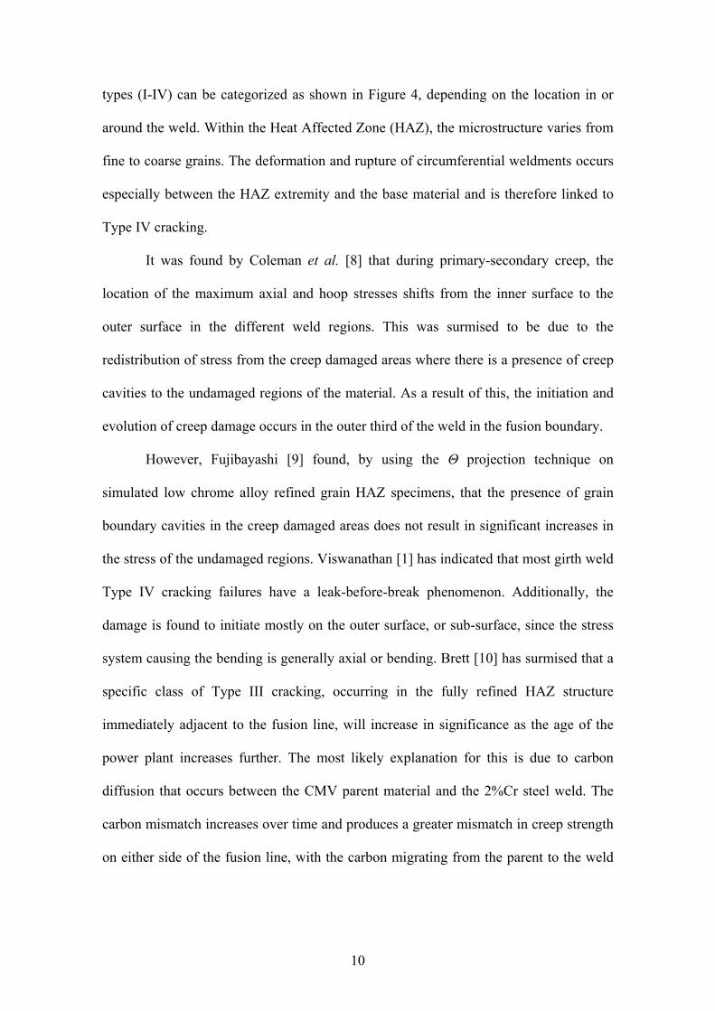
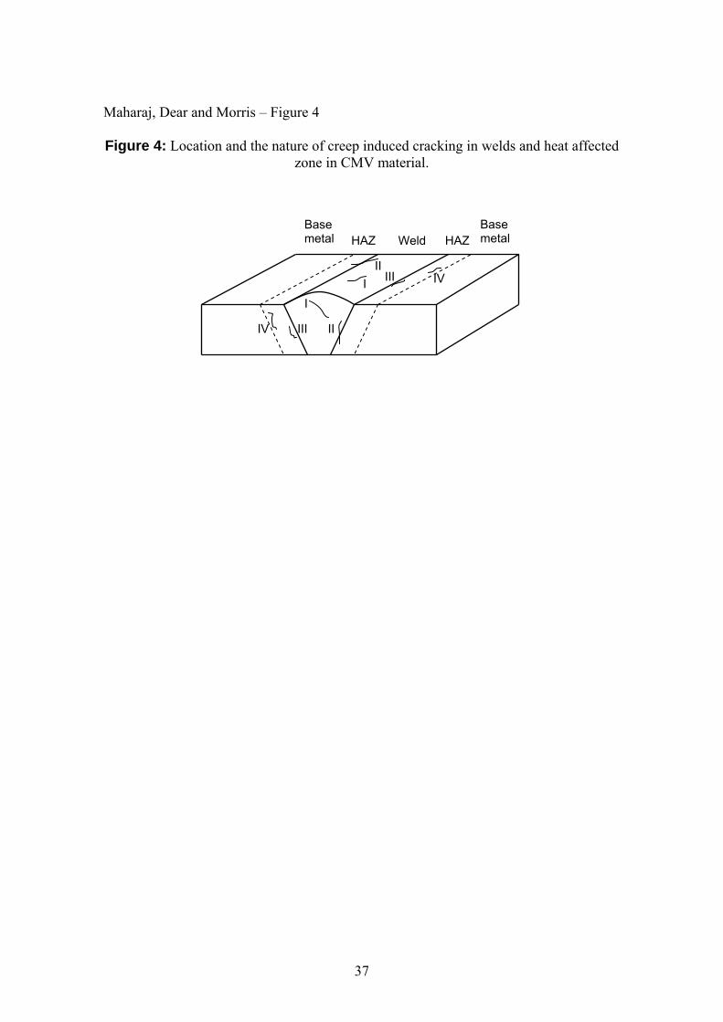
The complex thermo-mechanical nature of Ferritic welds leads to
inhomogeneous material properties around and within the welded metal. Four crack
10
types (I-IV) can be categorized as shown in Figure 4, depending on the location in or
around the weld. Within the Heat Affected Zone (HAZ), the microstructure varies from
fine to coarse grains. The deformation and rupture of circumferential weldments occurs
especially between the HAZ extremity and the base material and is therefore linked to
Type IV cracking.
It was found by Coleman et al. [8] that during primary-secondary creep, the
location of the maximum axial and hoop stresses shifts from the inner surface to the
outer surface in the different weld regions. This was surmised to be due to the
redistribution of stress from the creep damaged areas where there is a presence of creep
cavities to the undamaged regions of the material. As a result of this, the initiation and
evolution of creep damage occurs in the outer third of the weld in the fusion boundary.
However, Fujibayashi [9] found, by using the Θ projection technique on
simulated low chrome alloy refined grain HAZ specimens, that the presence of grain
boundary cavities in the creep damaged areas does not result in significant increases in
the stress of the undamaged regions. Viswanathan [1] has indicated that most girth weld
Type IV cracking failures have a leak-before-break phenomenon. Additionally, the
damage is found to initiate mostly on the outer surface, or sub-surface, since the stress
system causing the bending is generally axial or bending. Brett [10] has surmised that a
specific class of Type III cracking, occurring in the fully refined HAZ structure
immediately adjacent to the fusion line, will increase in significance as the age of the
power plant increases further. The most likely explanation for this is due to carbon
diffusion that occurs between the CMV parent material and the 2%Cr steel weld. The
carbon mismatch increases over time and produces a greater mismatch in creep strength
on either side of the fusion line, with the carbon migrating from the parent to the weld
11
metal. Increased amounts of M23C6 carbides are formed in the weld metal,
compromising the carbon content in the adjacent fully refined HAZ zone.
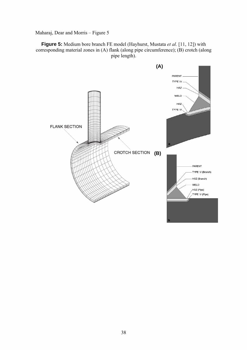
Hayhurst, Mustata et al. [11, 12], have demonstrated the complexity of creep
situation to be analysed (see Figure 5). This shows a three-dimensional mesh model of a
medium bore branch. Through the combination of the constitutive equations generated
for each of the zones shown in Figure 5 and Three-Dimensional (3D) Finite-Element
(FE) modelling, close agreement was achieved between the results of metallographic
examinations of a tested vessel and predicted damage fields of a medium bore branched
CMV pipe under constant pressure. This area of research reinforced the point that the
3D analysis was strongly dependent on knowing the correct thickness of both the coarse
grain HAZ and Type IV cracking susceptible zones. The thickness of these zones is
highly dependent on the weld geometry (thickness, joint preparation) and weld
procedure (welding process, time, and electrode). The resultant high degree of
uncertainty can be conclusively removed through metallographic examination of the
service-exposed specimens. The analysis assumed constant pressure and temperature
conditions but did not account for manufacturing defects that may accompany new pipe
material. Bolton et al. [13] indicate that these manufacturing defects can play a
significant part in the initiation and evolution of creep.
Review of Methods
Several methods or techniques can be applied to estimate the level of accumulated creep
damage, and hence remnant life, either from site inspections or service exposed material
extracted from plant. Usually decisions to undertake major repairs or replacements are
based on the findings from a number of different methods to ensure consistency.

12
These techniques can be broadly grouped into traditional site based, sample
extraction and assessment, and recent developments associated with high temperature
strain measurement. The techniques are subsequently described along with their
associated strengths and weaknesses.
Site investigations
These techniques are deployed during a planned site overhaul and have been identified
as part of a pre-planned inspection schedule. Typically the scope of the inspection
schedule reflects site specific issues and also, wherever possible, considers the threat of
emerging issues associated with similar plant on other sites. Hardness testing and
replication are presently the most applied survey techniques.
Dimensional effects
Maharaj [14] obtained a high degree of correlation between the change in outer
diameter of an iron base superalloy tube and the development of creep. Creep was
quantified by calculating the percentage creep cavities within the metal matrix.
However, there are other problems to be considered for steam pipes made of CMV steel
and other materials. Care is needed in taking into account the dimensions of working
pipes that have undergone high temperature oxidation.
Traditionally during a site outage, convenient locations are nominated for
diametrical measurements using micrometers. These measurements can be taken over
installed creep pips or directly over the pipe surface, however the results must be
corrected for oxide growth and temperature before being used to estimate the effective
13
strain rate over the operating period. These measurements are useful if obtained with
care, and are still used today to provide estimates of strain rate on ageing plant.
Hardness measurements
Site hardness measurements are a technique that can be applied as a screening tool to
identify areas of pipework that are softening over time due to creep, which can prompt
additional investigations. A high degree of scatter has been observed with these
measurements. However, recent developments in the technique [15] have shown that it
can be used in a predictive sense to estimate remnant life.
Replica metallography
Replica metallography is a plant offline NDT technique, applied generally during
maintenance. It can quantitatively and qualitatively monitor the growth of cavities in
low alloy Ferritic steels subjected to high temperature service. The replica preparation
process follows the same initial steps of grinding, polishing, and etching as done with
preparation of a laboratory microstuctural specimen. The final step involves replicating
the microstructural pattern onto a film that is subjected to microstructural evaluation
thereafter.
Payten [16] has observed that, for a creep finite element model of a main steam
line branch connection, Type IV cracking would not only manifest itself on the external
surface of the weld HAZ but would be more widespread through the thickness. A
surface technique such as replication would need to be accurate in its quantitative or
qualitative creep life-assessment as the time between damage indications on the surface
and full thickness damage is suggested to be very limited.
14
In light of the difficulties of traditional replication techniques, alternative
techniques have been developed to assist in improving the level of detail and resolution
required to quantitatively account for the coarsening of precipitates, nucleation, growth
and orientation of cavities, micro-cracks and subsequent cracking. Venkataraman et al.
[17] developed electropolishing units called CEPIN (Controlled ElectroPolisher IN-situ)
and APINE (All Position IN-situ Electropolisher) and applied them to Cr-Mo steels.
Components to be replicated are mechanically ground and polished. Final
electropolishing is accomplished using CEPIN (for flat and slightly inclined positions)
or APINE (for the vertical and overhead positions). Nital is used as the etching agent.
Transparent cellulose acetate tapes of 0.02 mm and 0.1 mm thickness are applied with
acetone as the softener. The replicas are gold sputtered and can be examined in
polarised light contrast metallurgical microscopes up to a magnification of x1600.
Venkataraman et al. [17] obtained consistent high quality microstructures. They used
these replicas to estimate creep pores (CP), oriented creep pores (OCP), and creep
cracks (CC).
Compared to other site investigative techniques, replica metallography is a time
consuming process whose accuracy increases as the number of samples taken increases.
The estimation of cavity population in the form of CP, OCP, and CC can supply
important information with regards to creep remaining life. However, this is limited to
the low alloy Ferritic steels. For higher alloys steels having between 9-11% Cr,
Letofsky et al. [18] could not clearly prove a correlation between the creep resistance
and the size distribution of particular cavity population. This finding has been a catalyst
for the development of new techniques for supercritical plant that will use higher alloy
steels. Notwithstanding this, replication remains a well tried and tested procedure on
site and is still one of the mainstays in any replacement/repair decision.
15
Ultrasonic testing
Significant advances have been made with respect to the relationship between creep
cavities and ultrasonic velocity, attenuation and absorption measurements in CMV and
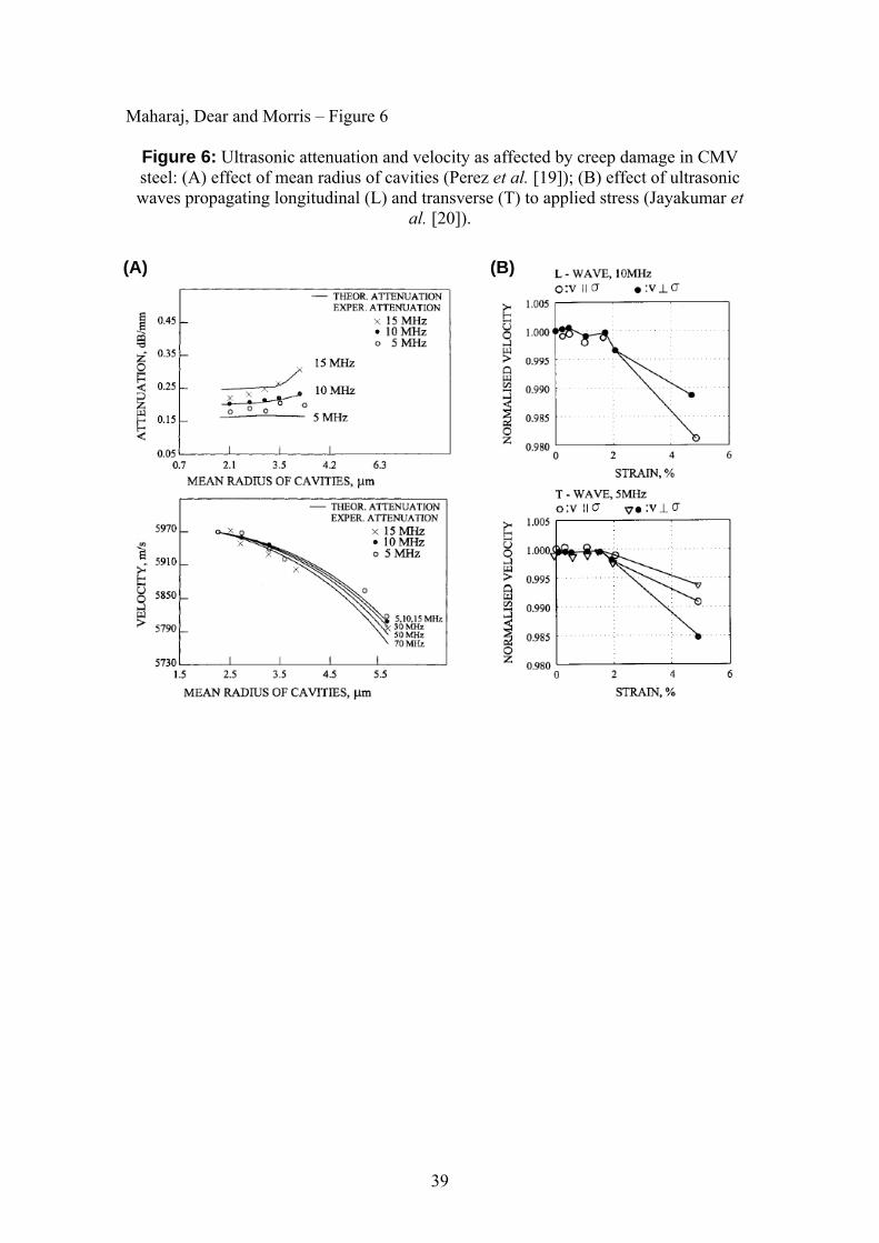
low alloy Cr-Mo steel material. Figure 6A shows results by Perez et al. [19] as to the
variation in the theoretical and experimental ultrasound attenuation and velocity values
as a function of mean radius of cavities in CMV steel. These results revealed good
correlation between creep cavity size (which is strongly related to the degree of creep)
and ultrasonic data. Ultrasonic velocity measurements were used by Jayakumar et al.
[20] to assess the creep damage in service exposed CMV material. It was observed that
velocity decreases at higher creep strains (Figure 6B). Furthermore, the velocity change
is less for transverse waves compared to longitudinal waves.
Kalyanasundaram et al. [21] found that ultrasonic absorption increased with
increasing creep strain and associated damage in CMV material. The behaviour was
attributed to the altered dislocation structure that leads to a larger contribution to the
dislocation damping. Additionally, oscillation behaviour of the reverberation signals
was observed and it was concluded that a non-contact reverberation method with laser
ultrasonics has the potential for assessment of creep damage.
In the attempt to minimize the UT time and thereby increase its applicability to
the power station industry, significant research has been conducted into Linear Phased
Array (LPA) technology [22]. Sound beams of many angles are generated sequentially
by a single probe, increasing the probability of flaw detection. Compared to the
traditional single angle shear wave inspections, a sector scan using LPA can be done in
milliseconds instead of scanned traditionally in a few seconds.
Bisbee [23] has documented a 3-step methodology for the detection of creep
cracks and creep incipient activity (in the form of cavities) in high-temperature header
16
girth welds. First level screening is done using long-range guided wave UT to identify
welds with susceptible creep cracks. The second activity involves the use of either Time
Of Flight Diffraction (TOFD) or LPA for verification and identification of the creep
activity. The final step employs a Focused Annular Array Transducer System (FATS) to
generate focussed array ultrasonic images. This last activity has the required resolution
for the detection of incipient subsurface initiated creep cavitation damage and the ability
to differentiate this damage from manufacturing/fabrication inhomogenities. As with
the development of all inspection techniques a key aspect is validation, which should
include correlation against observed service degradation.
Acoustic emission
The Acoustic Emission (AE) technique employs the use of sound and ultrasound wave
signals that are emitted during deformation of an object. These signals can be acquired
by sensors mounted throughout the length of a pipeline. The signal information can be
used for the identification of a flaw location. With proper validation, the flaw type and
criticality level can also be categorized.
Companies such as Margan, Inc. [24] have installed AE monitoring systems on
plant and the technique has shown past success in revealing and classifying propagating
cracks. Ascertaining the evolution and progression of creep cavities are inherently more
difficult to determine using AE. The major issues are the high sensitivity required to
identify the creep cavity, interpreting the relationship between the cavity response signal
and the damage, and factoring out manufacturing/fabrication inhomogenities.
17
Magnetic testing
Magnetic methods can be used for the characterisation of creep defects in ferromagnetic
materials. For a demagnetised material that is subjected to an external varying magnetic
field, the relationship between magnetic field strength (H) and magnetic flux density (B)
is shown in Figure 7. During magnetization, the magnetic field, H, is increased until Bsat
is reached. When H is reduced to zero, the ferromagnetic material will exhibit a residual
value called the remnant flux density Br. Upon reversal of the magnetic field, the plotted
relationship in Figure 7 will have an associated coercivity, Hc. Any change in the
material microscopic parameters such as creep damage, density and arrangement of
dislocations, nature of secondary phases, and grain size would be reflected in these
micro-magnetic parameters. Studies performed by Govindaraju et al. [25], Negley et al.
[26], and Mitra et al. [27] on Cr-Mo steels revealed that a lower Br is indicative of creep
damage. The level of creep damage has also been found to be related to the product of
Hc and Br. Raj [28] has surmised that these magnetic techniques surpass UT techniques
with respect to identifying progressive creep damage. It is anticipated that this technique
will become commercially viable as more research work continues with respect to
correlation to in-service degradation.
Sample Extraction and Assessment Techniques
Metallographic destructive testing
The most conclusive method of accurately acquiring data for remaining life assessments
of any metallic component is through the use of destructive testing. In particular, this
activity involves continuous metallographic examination of service exposed samples
that have been extracted. In addition to conclusively determining the sole cause of the
18
damage mechanism being due to creep as found by Maharaj et al. [29], sufficient
information can be acquired to determine the stage of the creep evolution. Investigation
of the carbide precipitate coarsening and cavity formation over time can provide
accurate information of the degree of creep and furthermore how close the component
may be to rupture failure.
The major obstacle to overcome is trying to obtain meaningful samples, which
often requires removal and replacement of piping sections. Multiple samples should be
obtained so that there is reliable representation of the entire creep vulnerable pipe-work
set. A sufficient plant maintenance window is therefore required.
Sample mechanical testing
The standard uni-axial or multi-axial creep tests can yield valuable amounts of high
temperature mechanical property data. This information can assist in the determination
of the remaining life of an extracted sample. However, Bolton et al. [13] emphasises
that any creep remaining life laboratory test, especially with regards to low alloy Ferritic
steels, must account for the coarsening of the carbide precipitates that occurs during
service. Also, damage mechanisms can be stress state sensitive so that uniaxial tests
may not be applicable to service conditions. Finally, minor differences in furnace heat
batches may lead to significant differences in the initiation and evolution of a cavity
formation damage mechanism. Therefore, laboratory tests should use the same batch of
material as in service. Small punch testing is a candidate that can provide the required
mechanical properties through small sample extraction. Testing done by Sujimoto et al.
[30] on a low alloy steel have shown good correlation between the small punch creep
test and standard uni-axial creep test data.
19
Assessment techniques
Temperature and pressure data captured from plant at suitable intervals have been used
to provide another estimate of creep life consumption. However, on many occasions it
has indicated life exhaustion when site investigation showed no sign of creep damage.
One reason for this discrepancy is that the design codes (BS 806 [31], BS 5500
[32], BS 1113 [33]) for high-temperature pressurized components are based on uni-axial
stress rupture properties of the parent pipe material. BS 806 [31] calculates the
allowable working stress σw as:
σw = (mean stress to cause rupture in 100,000 hours) / (safety factor) (1)
The safety factor used is mostly in the range 1.45 to 2.10 depending on the material
working conditions. This range would subsequently result in a significant variance in
the predicted rupture lives. Additionally, based on long remaining life (approximately
200,000 hrs) found on some service exposed CMV material, Williams [34] deduced that
the creep rupture extrapolation rules was at best approximate. Furthermore, Hayhurst
and Goodlal [35] observed that the creep failure in weldments occurred earlier than the
expected design rupture times owing to non-conservative weld strength reduction
factors, different mechanical properties and state of the weld material and the effect of
multi-axial stress states.
In light of the issues faced in obtaining accurate remaining life estimations using
design codes, predictive techniques have been developed and refined, some having the
ability to describe the entire creep curve by a single equation. Popular techniques
include the projection technique [36, 37], the Materials Properties Council (MPC)
method developed by Prager [38], and the R5 procedures that are presently maintained
20
by British Energy Generation Limited. The successful validation of some of these
methods has led to their subsequent inclusion, with minor modifications, in assessment
codes such as BS 7910 [39], and American Petroleum Institute (API) 579 [40]. In
reality, design code estimates of remnant life have a part to play in assessing potential
trends resulting from changes in operational profile driven by commercial needs.
New Developments in Strain Monitoring
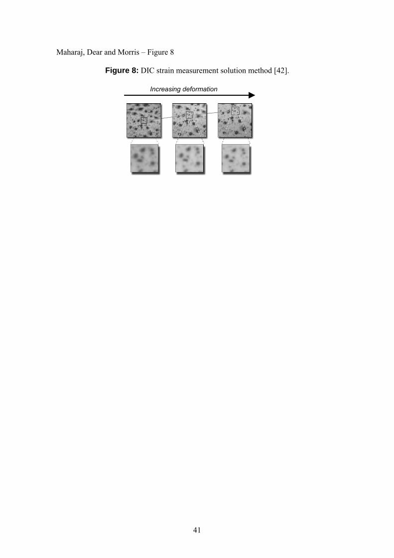
Digital Image Correlation (DIC)
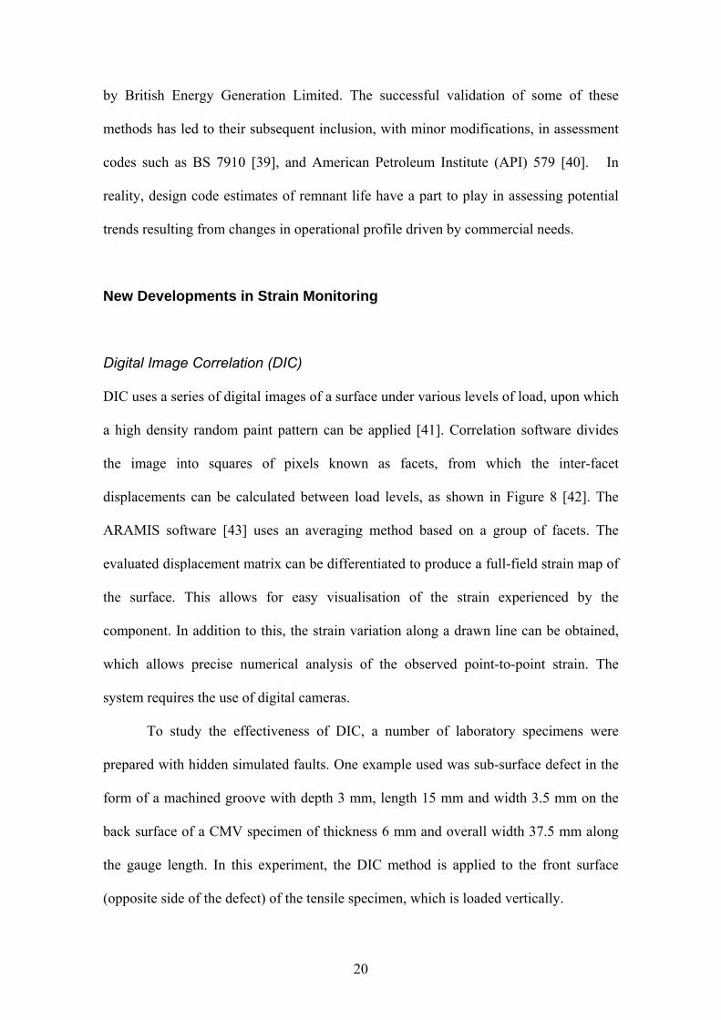
DIC uses a series of digital images of a surface under various levels of load, upon which
a high density random paint pattern can be applied [41]. Correlation software divides
the image into squares of pixels known as facets, from which the inter-facet
displacements can be calculated between load levels, as shown in Figure 8 [42]. The
ARAMIS software [43] uses an averaging method based on a group of facets. The
evaluated displacement matrix can be differentiated to produce a full-field strain map of
the surface. This allows for easy visualisation of the strain experienced by the
component. In addition to this, the strain variation along a drawn line can be obtained,
which allows precise numerical analysis of the observed point-to-point strain. The
system requires the use of digital cameras.
To study the effectiveness of DIC, a number of laboratory specimens were
prepared with hidden simulated faults. One example used was sub-surface defect in the
form of a machined groove with depth 3 mm, length 15 mm and width 3.5 mm on the
back surface of a CMV specimen of thickness 6 mm and overall width 37.5 mm along
the gauge length. In this experiment, the DIC method is applied to the front surface
(opposite side of the defect) of the tensile specimen, which is loaded vertically.
21
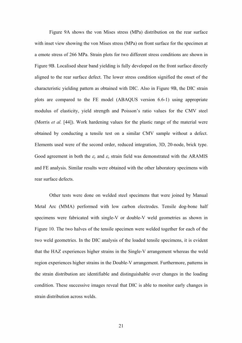
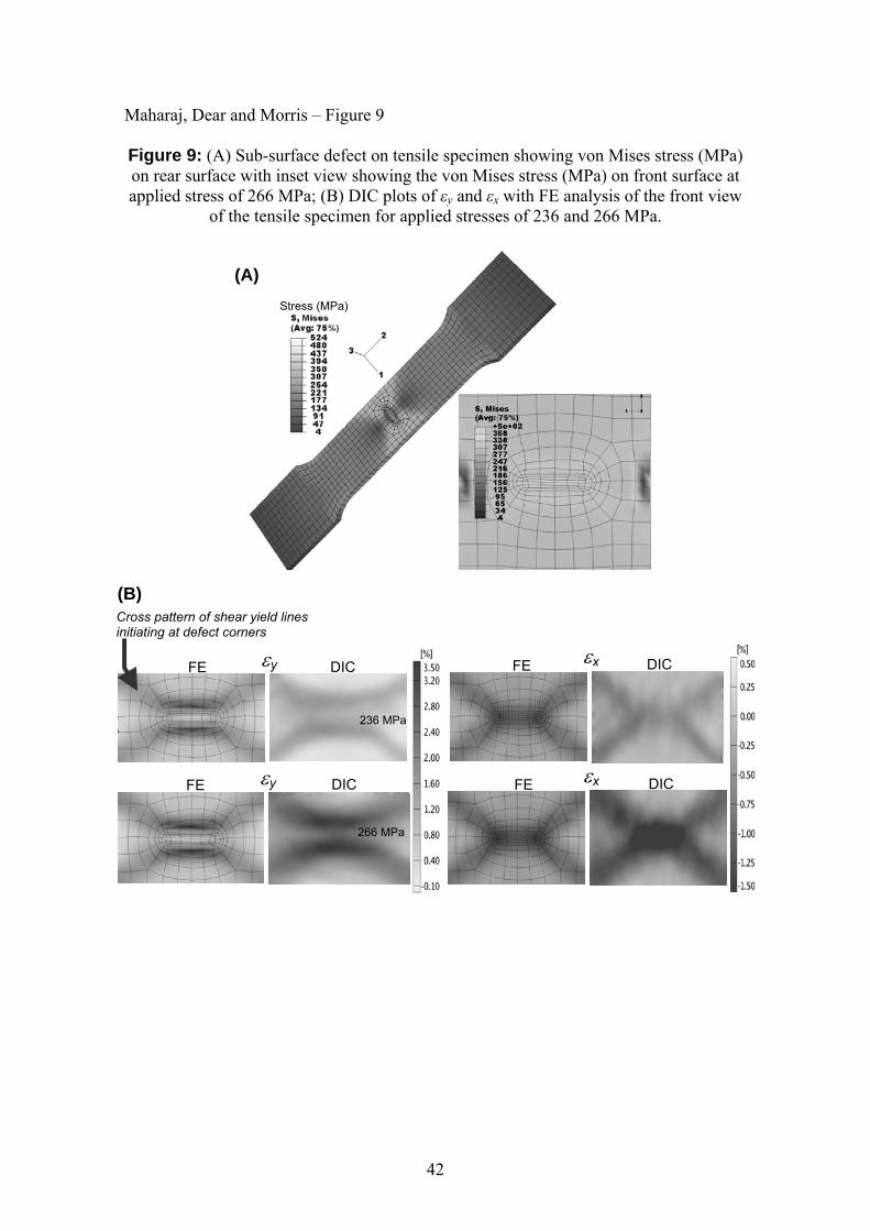
Figure 9A shows the von Mises stress (MPa) distribution on the rear surface
with inset view showing the von Mises stress (MPa) on front surface for the specimen at
a emote stress of 266 MPa. Strain plots for two different stress conditions are shown in
Figure 9B. Localised shear band yielding is fully developed on the front surface directly
aligned to the rear surface defect. The lower stress condition signified the onset of the
characteristic yielding pattern as obtained with DIC. Also in Figure 9B, the DIC strain
plots are compared to the FE model (ABAQUS version 6.6-1) using appropriate
modulus of elasticity, yield strength and Poisson’s ratio values for the CMV steel
(Morris et al. [44]). Work hardening values for the plastic range of the material were
obtained by conducting a tensile test on a similar CMV sample without a defect.
Elements used were of the second order, reduced integration, 3D, 20-node, brick type.
Good agreement in both the y and x strain field was demonstrated with the ARAMIS
and FE analysis. Similar results were obtained with the other laboratory specimens with
rear surface defects.
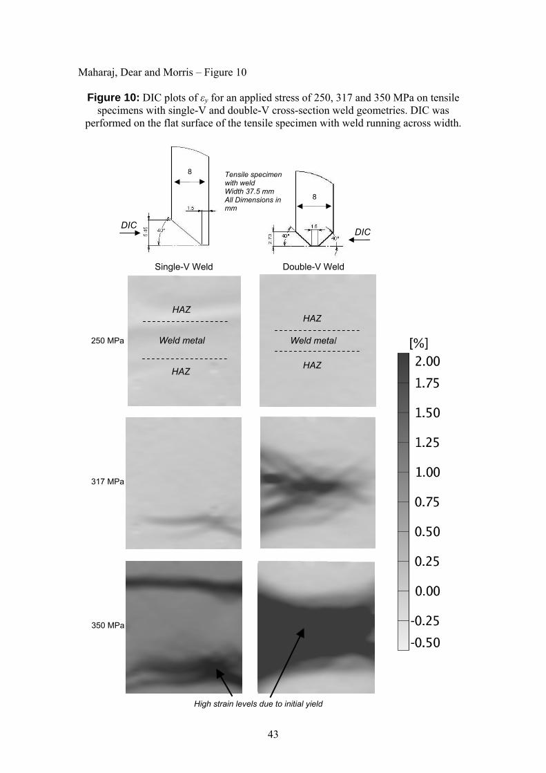
Other tests were done on welded steel specimens that were joined by Manual
Metal Arc (MMA) performed with low carbon electrodes. Tensile dog-bone half
specimens were fabricated with single-V or double-V weld geometries as shown in
Figure 10. The two halves of the tensile specimen were welded together for each of the
two weld geometries. In the DIC analysis of the loaded tensile specimens, it is evident
that the HAZ experiences higher strains in the Single-V arrangement whereas the weld
region experiences higher strains in the Double-V arrangement. Furthermore, patterns in
the strain distribution are identifiable and distinguishable over changes in the loading
condition. These successive images reveal that DIC is able to monitor early changes in
strain distribution across welds.
22
It is the intent that a high temperature DIC measurement technique will not only
be able to monitor the strain rate but to also attempt to categorize the nature of the
defect as close to its infancy as possible. The limit to this early defect pattern detection
and recognition is approximately 500 με, which is dictated by the image processing
software [42] used. The promising findings have lead to further research in this area that
will encompass:
Categorization of different strain patterns based on different defect geometries
e.g. pattern recognition of Type IV defects and defects in the extrados of piping
bends in CMV material. This will encompass experimental testing on smaller
defect sizes and FE modelling of creep cracks on piping. The ability to detect
sub-surface defect information from this surface measurement technique will
also be further investigated. (Chris, could you have a think about the bullet
point above. From my perspective you are quite right is saying that the aim is
to ‘attempt to categorize the nature of the defect as close to its infancy as
possible’. I you should add some words that highlight that detection of the
accumulation of ‘creep damage’ as early as possible is the driver, which would
manifest itself as an increasing strain rate that may be quite local to a HAZ.
This would occur prior to void linkage and macro-cracking, which may be more
easily detected by replication and conventional NDT. I see the DIC as an
invaluable technique for detection of damage accumulation at a very early
stage, thereby prompting other site investigations, which may include
replication etc). So DIC would primarily be used initially across welds, if
ARCMAC is used in tandem then ARCMAC can effectively provide a
calibrated reference point-to-point strain value, against which the integrated
DIC value from the 2D surface strain can be compared.
23
Investigation of image degradation due to high temperature and environmental
(weathering and contamination) conditions. Initial tests done at high
temperature (600oC) [45] have shown that the image to remain robust after a 3
month test. Longer tests will be carried out to ensure that the image quality
remains high for at least one maintenance cycle. At that juncture, the strain map
can be recorded and the image can be re-applied for the next maintenance cycle.
Investigation of the application of 2D images techniques on high curvature
piping surfaces and reducing the time it takes to acquire a 3D image on-site.
Auto Referenced Creep Measurement And Control (ARCMAC)
The ARCMAC method, developed by E.ON UK, has been in successful use for some
years initially as a uniaxial creep strain measurement device and recently developed into
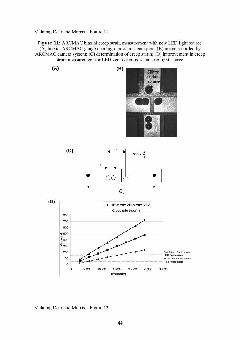
a biaxial strain measurement system [46, 47]. The ARCMAC system consists of a
Portable Charge-Coupled Device (CCD) camera unit, ARCMAC strain gauge, gauge
installation tool, portable laptop computer and image analysis software. The strain
gauges consist of two Inconel gauge plates with fixed Silicon Nitride target spheres.
The two strain gauges are stud welded as shown in Figure 11A and the CCD camera
unit uses a collimated light source to illuminate the spherical Silicon Nitride target
spheres as shown in Figure 11B. Over time, strain values are recorded from the
movement of the bright circular points of light from each Silicon Nitride sphere and
these are compared for creep life determination. Two Silicon Nitride target spheres
provide a reference distance of 3 mm on one of the Inconel gauge halves.
Image analysis software is used to determine the separation of the centres of the
circular points of light in each direction provided by the two targets on one of the
Inconel gauge halves. The strain is calculated as follows:
24
A
GA
tB
A
tB
L
)0()(
(2)
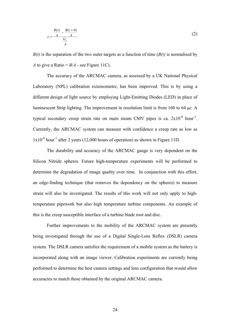
B(t) is the separation of the two outer targets as a function of time (B(t) is normalised by
A to give a Ratio = B/A - see Figure 11C).
The accuracy of the ARCMAC camera, as assessed by a UK National Physical
Laboratory (NPL) calibration extensometer, has been improved. This is by using a
different design of light source by employing Light-Emitting Diodes (LED) in place of
luminescent Strip lighting. The improvement in resolution limit is from 160 to 64 με. A
typical secondary creep strain rate on main steam CMV pipes is ca. 2x10⁻⁸ hour-1.
Currently, the ARCMAC system can measure with confidence a creep rate as low as
1x10⁻⁸ hour-1 after 2 years (12,000 hours of operation) as shown in Figure 11D.
The durability and accuracy of the ARCMAC gauge is very dependent on the
Silicon Nitride spheres. Future high-temperature experiments will be performed to
determine the degradation of image quality over time. In conjunction with this effort,
an edge-finding technique (that removes the dependency on the spheres) to measure
strain will also be investigated. The results of this work will not only apply to high-
temperature pipework but also high temperature turbine components. An example of
this is the creep susceptible interface of a turbine blade root and disc.
Further improvements to the mobility of the ARCMAC system are presently
being investigated through the use of a Digital Single-Lens Reflex (DSLR) camera
system. The DSLR camera satisfies the requirement of a mobile system as the battery is
incorporated along with an image viewer. Calibration experiments are currently being
performed to determine the best camera settings and lens configuration that would allow
accuracies to match those obtained by the original ARCMAC camera.

25
Combination of DIC and ARCMAC
A synergistic integration is achieved through the use of a combined ARCMAC/DIC
system. This is with the ARCMAC system providing accurate point-to-point strain
measurement and the DIC showing how the 2D strain is distributed between the
ARCMAC monitoring points. The ARCMAC uni-axial strain measurement will provide
important feedback on the 2D strain field variation provided by DIC, for example across
a parent/HAZ/weld interface.
Future experiments to further integrate the two techniques will involve:
Investigation of the impact of part of the DIC pattern being obscured by the
ARCMAC gauges. Experimentation on different defect geometries will be
performed do determine whether the defect pattern can still be resolved and
distinguished through interpolation or whether a gauge redesign is required.
Reducing the time taken to acquire an image through the use of a single camera
system that can capture both ARCMAC and DIC data simultaneously.
Discussion
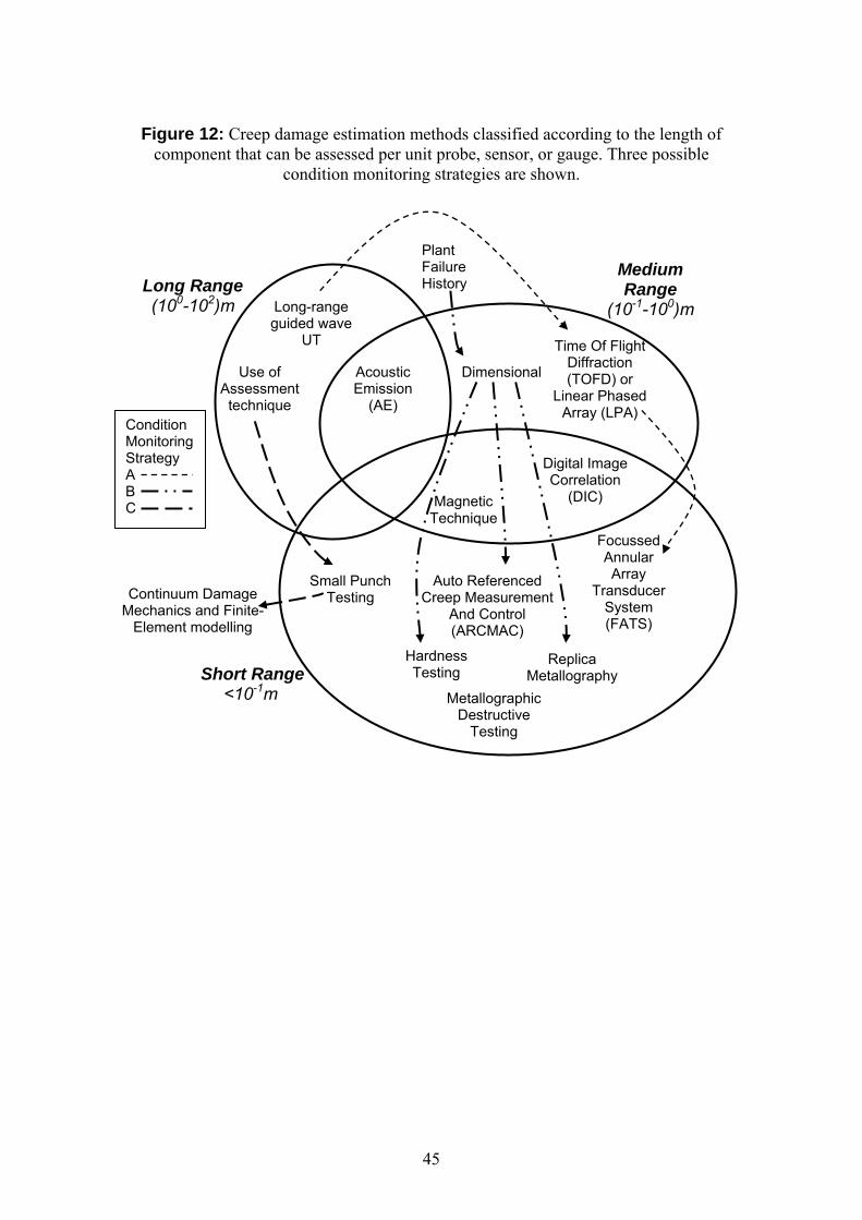
The optimal creep condition monitoring strategy will be dependent on plant size,
criticality of operations, skill/training of workforce and cost. This strategy can be a
combination of any of the methods reviewed. These methods can be classified into
ranges (the length of component that can be assessed per unit measurement probe,
sensor or gauge) as shown in Figure 12. Generally, a greater length of assessment
capability corresponds to a lower ability to detect earlier stages of creep. Three possible
creep condition monitoring strategies (A, B, and C) are presented as an illustration.
26
Strategy A is an example of a plant whose technical workforce is adept in the
use of UT as an en-suite tool to find creep susceptible piping by firstly using long-range
guided waves, confirming any anomalies through the use of TOFD or LPA, and finally
accurately monitoring and tracking the creep activity using FATS. The critical aspect of
this strategy is calibration and validation of the method through testing specimens with
known defects and on service-exposed specimens. Also, the technique must be
continually updated by researching the work of others in this field.
Strategy B can be the case of an aged plant whose plant failure history
documentation is thorough. This documentation is analysed to determine the creep
susceptible areas of the plant. Dimensional checks are used to confirm creep growth in
these areas. A combination of hardness testing, replica metallography, and an accurate
strain method such as ARCMAC are used to track creep degradation.
A plant technical team that is very proficient in modelling techniques may adopt
Strategy C. An applicable assessment technique can be used in conjunction with a
method such as small punch testing to acquire localised high temperature creep data. A
Continuum Damage Mechanics (CDM) FE model is generated to reveal the creep
susceptible sections of the piping. In this approach, quantities such as axial and bending
loads must be accurately known else the model solution would be approximate.
In reality any combination of the above could be adopted to provide an effective
integrity management process. Therein lies the issue; which approach should a Utility
adopt? especially when the consequences of a failure of such high energy systems could
be very serious in terms of personnel safety and commercial loss. The adoption of an
integrity management strategy described within this paper should be undertaken with
due regard to the relevant country legislative framework. In addition it is clear that
success, in terms of minimising the risk of a failure, will depend on close working
27
between staff involved in Operations and Maintenance, Production, Technical Support,
Management and the regulator. This invariably must be achieved within a competitive
market framework for Electricity Generation, which for example exists in the UK. This
presents significant challenges for the integrity management of current plant, and also
for planned new build fossil fired stations in the UK. This future plant will operate
under more severe conditions and will be manufactured from materials that may not be
as amenable to inspection and assessment using current proven techniques.
Conclusion
In this paper attention has mostly been given to creep processes in power station low
alloy steam pipes and the methods for estimating the onset and progression of these
processes. Information is also needed on the approach to the end of reliable life of other
power station components and parts. Preventative maintenance and condition
monitoring strategies are needed to embrace a wide range of life monitoring and other
data to decide on component replacement and repair tasks. The objective is to achieve a
timely and cost effective programme to ensure the integrity of the power station plant
for the next operational period. The planning task to achieve this objective is demanding
as the preventative maintenance programme can be different on each occasion.
Improving the monitoring methods and taking advantage of advanced
instrumentation and other related technologies (such as the methods presented in this
paper) will assist in obtaining more accurate creep data and of other failure processes. It
is envisaged that an optimised combination of any of these methods reviewed can
become a benchmarked present and future creep condition monitoring strategy.
28
ACKNOWLEDGEMENTS
Mr Maharaj thanks the University of Trinidad and Tobago (UTT) for the sponsorship
provided to pursue a PhD at Imperial College London. The authors also acknowledge
the support of E.ON UK for provision of equipment and specimens.
REFERENCES
1. Viswanathan, R. (2000) Life management of high-temperature piping and tubing in
fossil power plants. J. of Pressure Vessel Tech. 122, 305-316.
2. British Standard (1990) BS3604-1, Steel pipes and tubes for pressure purposes:
ferritic alloy steel with specified elevated temperature properties. Specification for
seamless and electric resistance welded tubes. British Standards Publishing Limited,
London.
3. Purmensky, J. (2000) Creep resistance and structural stability of low-alloy CrMo and
CrMoV steels. Key Engg. Mat. 171-174, 419-426.
4. American Society of Mechanical Engineers (2004) SA-335, Standard specification
for seamless ferritic alloy-steel pipe for high temperature service.
5. Liaw, P.K., G.V. Rao, and Burke, M.G. (1991) Creep fracture-behaviour of 2.25Cr-
1Mo welds from a 31-year-old fossil power-plant. Mat. Sci. & Engg. Part A, Structural
materials 131, 187-201.
6. Steen, M. and De Witte, M. (1987) Impact of Structural Instability on the
Extrapolation of Short Term Creep Test Results. I. Deformation Behaviour. Creep and
Fracture of Engg. Mat. and Struct., Swansea, 773-787.
7. Dobrzanski, J. (2004) Internal damage processes in low alloy chromium-
molybdenum steels during high-temperature creep service. J. of Mat. Processing Tech.
157, 297-303.
29
8. Coleman, M.C., J.D. Parker, and Walters, D.J. (1985) The behaviour of ferritic
weldments in thick section 0.5Cr-0.5Mo-0.25V pipe at elevated temperature. Int. J. of
Pressure Vessels and Piping 18, 277-310.
9. Fujibayashi, S. (2004) The effect of grain boundary cavities on the tertiary creep
behaviour and rupture life of 1.25Cr-0.5Mo steel welds. Iron and Steel Inst. of Japan
Int. 44, 1441-1450.
10. Brett, S.J. (2004) Type III cracking in 1/2 CrMoV steam pipework systems. Sci. and
Tech. of Welding and Joining 9, 41-45.
11. Hayhurst, D.R., Hayhurst, R.J., Mustata, R., and Vakili-Tahami, F. (2005) CDM
predictions of creep damage initiation and growth in ferritic steel weldments in a
medium bore branched pipe under constant pressure at 590 deg. C using a five-material
weld model. Proc. Math., Phy., and Engg. Sci. 461, 2303-2326.
12. Mustata, R., Hayhurst, R.J., Hayhurst, D.R., and Vakili-Tahami, F. (2006) CDM
predictions of creep damage initiation and growth in ferritic steel weldments in a
medium-bore branched pipe under constant pressure at 590 degrees C using a four-
material weld model. Archive of App. Mech. 75, 475-495.
13. Bolton, C.J., B.F. Dyson, and Williams, K.R. (1980) Metallographic methods of
determining residual creep life. Mat. Sci. and Engg. Part A 46, 231-239.
14. Maharaj, C. (2001) Creep analysis of Incoloy 800H reformer outlet pigtail tubes,
Mechanical Engineering B.Sc. Final Year Project, The University of the West Indies,
St. Augustine.
15. Allen D.J. and Fenton S.T. (2007) A hardness-based creep rupture model for new
and service aged P91 steel, Int. Conf. on Life Management and Maintenance for Power
Plants (BALTICA VII), Helsinki - Stockholm - Helsinki.
30
16. Payten, W. (2006) Large scale multi-zone creep finite element modelling of a main
steam line branch intersection. Int. J. of Pressure Vessels and Piping 83, 359-364.
17. Venkataraman, G., Ramesh, T.R., Veeraragavan, R., and Babu, R.S. (1996)
Remaining life assessment of thermal power plant components by in-situ
metallography. Trans. of the Indian Inst. of Metals 49, 443-451.
18. Letofsky, E. and Cerjak, H. (2004) Metallography of 9Cr steel power plant weld
microstructures. Sci. and Tech. of Welding and Joining. 9, 31-36.
19. Perez, C., R. Martinez-ona, and Banes, J. (1994) Proc. of the 6th European Conf.
on Non-Destructive Testing. Nice.
20. Jayakumar, T., B. Raj, and Rodriguez, P. (1995) Proc. of the Int. Conf. on Comp.
Engg. Sci., Comp. Mech. '95: Theory and Applications 1, 1377-1382.
21. Kalyanasundaram, P., J. Reszat, and Paul, M. (1996) Absorption measurements on
creep damaged samples using the reverberation technique. Mat. Sci. Forum 1 & 2, 243-
250.
22. NDT (1999) Phased Array UT Applications Development at the EPRI NDE Center
[cited 2007; Available from: http://www.ndt.net/article/v04n10/gselby/gselby.htm]
23. L. Bisbee (2006) Enhanced methodologies used for the assessment of high-
temperature header girth welds. The Int. J. of Pressure Vessels and Piping 83, 835-845
24. Margan, Inc. (2007) [cited 2007; Available from: http://www.margan.com/].
25. Govindaraju, M.R., Kaminski, D.A., Devine, M.K., Biner, S.B., Jiles, D.C. (1997)
NDTE Int. 30, 11-17.
26. Negley, M., M.R. Govindaraju, and Jiles, D.C. (1993) Review of Progress in Quan.
Nondestructive Eval. 13B, 1817-1824.
27. Mitra, A., Z.J. Chen, and Jiles, D.C. (1994) Review of Progress in Quan.
Nondestructive Eval. 14B, 1733-1740.

31
28. Raj, B., T. Jayakumar, and Rao, K. (2003) Assessment of microstructures and
mechanical behaviour of metallic materials through non-destructive characterisation.
Int. Mat. Reviews 48, 273-325.
29. Maharaj, C. and Imbert, C. (2006) Failure analysis of Incoloy 800H Reformer outlet
pigtail tubes. Ind. Engg. and Management Conf., St. Augustine.
30. Sugimoro, T., Misawa, T., Doki, K., and Komazaki, S. (2005) Evaluation of
Toughness and Creep Properties of Aged Main Valve CrMoV Casting Steel by Using
Small Punch Specimens. J. of the Iron and Steel Inst. of Japan. 91, 4, 408-414.
31. British Standard (1993) BS 806, Specification for the design and construction of
ferrous piping installations for and in connection with land boilers. British Standards
Publishing Limited, London.
32. British Standard (1997) BS 5500, Specification for unfired fusion welded pressure
vessels. British Standards Publishing Limited, London.
33. British Standard (1999) BS 1113, Specification for design and manufacture of
water-tube steam generating plant (including superheaters, reheaters, and steel tube
economizers). British Standards Publishing Limited, London.
34. Williams, K.R. and Cane, B.J. (1979) Creep behaviour of 0.5Cr0.5Mo.25V steel at
engineering stresses. Mat. Sci. and Engg. 38, 199-210.
35. Hayhurst, D.R. and Goodall, I.W. (2003) Type IV and coarse grained HAZ creep
rupture of ferritic steel uni-loaded cross-weld test pieces: verification of 3-D parallel
CDM software, DAMAGE XXX, using 2-D analyses and experiments. Internal search
report no. CMM.03.01, UMIST, Manchester.
36. Evans, R.W. and Wilshire, B. (1985) Creep of metals and alloys. Predictive and
Quantitative Metallurgy Series. The Institute of Metals, Swansea.
32
37. Evans, M. (2001) High-temperature oxidation and the prediction of creep life for
0.5Cr-0.5Mo-0.25V steel. The J. of Strain Anal. for Engg. Design 36, 421-437.
38. Prager, M. (2000) The omega method-an engineering approach to life assessment. J.
of Press. Vessel Tech. 122, 273-280.
39. British Standard (2005) BS 7910, Guide to methods for assessing the acceptability
of flaws in metallic structures. British Standards Publishing Limited, London.
40. American Petroleum Institute (2000) API RP 579, Recommended practice for
fitness-for-service and continued operation of equipment.
41. Sjodahl, M. (1997) Accuracy in electronic speckle photography. App. Opt. 36, 2875-
2885.
42. GOM mbH Germany (2005) ARAMIS User Manual. ARAMIS v5.4.1.
43. GOM mbH Germany (2007) Deformation measurement system using Digital Image
Correlation. [cited 2007; Available from: http://www.gom.com].
44. Morris, A., Maharaj, C., Puri, A., Kourmpetis, M., and Dear, J. (2007) Researching
methods to study creep strain variations in power station steam plant. ASME PVP
2007/CREEP8, San Antonio.
45. Morris, A., Kourmpetis, M., Dear, J., Puri, A., and Maharaj, C. (2007) Resolution of
creep strain measurements using the ARCMAC strain monitoring system. ASME
PVP2007/CREEP8, San Antonio.
46. Morris, A., Dear, J., and Kourmpetis, M. (2006) Life Assessment by monitoring
biaxial strain-rates in high temperature steam pipelines. ASME PVP 2006/ICPVT-11,
Vancouver.
47. Morris, A., Dear, J., and Kourmpetis, M. (2006) High temperature steam pipelines -
Development of the ARCMAC creep monitoring system. Strain 42, 181-185.
33
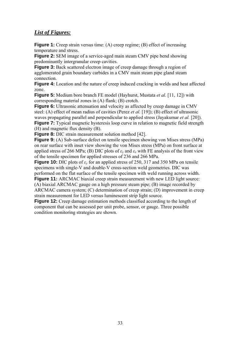
List of Figures: Figure 1: Creep strain versus time: (A) creep regime; (B) effect of increasing temperature and stress. Figure 2: SEM image of a service-aged main steam CMV pipe bend showing predominantly intergranular creep cavities. Figure 3: Back scattered electron image of creep damage through a region of agglomerated grain boundary carbides in a CMV main steam pipe gland steam connection. Figure 4: Location and the nature of creep induced cracking in welds and heat affected zone. Figure 5: Medium bore branch FE model (Hayhurst, Mustata et al. [11, 12]) with corresponding material zones in (A) flank; (B) crotch. Figure 6: Ultrasonic attenuation and velocity as affected by creep damage in CMV steel: (A) effect of mean radius of cavities (Perez et al. [19]); (B) effect of ultrasonic waves propagating parallel and perpendicular to applied stress (Jayakumar et al. [20]). Figure 7: Typical magnetic hysteresis loop curve in relation to magnetic field strength (H) and magnetic flux density (B). Figure 8: DIC strain measurement solution method [42]. Figure 9: (A) Sub-surface defect on tensile specimen showing von Mises stress (MPa) on rear surface with inset view showing the von Mises stress (MPa) on front surface at applied stress of 266 MPa; (B) DIC plots of εy and εx with FE analysis of the front view of the tensile specimen for applied stresses of 236 and 266 MPa. Figure 10: DIC plots of εy for an applied stress of 250, 317 and 350 MPa on tensile specimens with single-V and double-V cross-section weld geometries. DIC was performed on the flat surface of the tensile specimen with weld running across width. Figure 11: ARCMAC biaxial creep strain measurement with new LED light source: (A) biaxial ARCMAC gauge on a high pressure steam pipe; (B) image recorded by ARCMAC camera system; (C) determination of creep strain; (D) improvement in creep strain measurement for LED versus luminescent strip light source. Figure 12: Creep damage estimation methods classified according to the length of component that can be assessed per unit probe, sensor, or gauge. Three possible condition monitoring strategies are shown.
34
Maharaj, Dear and Morris – Figure 1
Figure 1: Creep strain versus time: (A) creep regimes; (B) effect of increasing temperature and stress.
ln ε ln ε
t t
Increasing σ, T Primary creep
Steady state creep
Tertiary creep
Elastic strain
(A) (B)
35
Maharaj, Dear and Morris – Figure 2
Figure 2: SEM image of a service-aged main steam CMV pipe bend showing predominantly intergranular creep cavities.
Intergranular creep cavities
40μm
36
Maharaj, Dear and Morris – Figure 3
Figure 3: Back scattered electron image of creep damage through a region of agglomerated grain boundary carbides in a CMV main steam pipe gland steam
connection.
5μm
Agglomerated grain boundary carbides
Creep cavities and cracking
37
Maharaj, Dear and Morris – Figure 4 Figure 4: Location and the nature of creep induced cracking in welds and heat affected
zone in CMV material.
Weld HAZ HAZ Base metal
Base metal
I
II
II III
III
IV
IV
I
38
Maharaj, Dear and Morris – Figure 5
Figure 5: Medium bore branch FE model (Hayhurst, Mustata et al. [11, 12]) with corresponding material zones in (A) flank (along pipe circumference); (B) crotch (along
pipe length).
(A)
(B)
39
Maharaj, Dear and Morris – Figure 6
Figure 6: Ultrasonic attenuation and velocity as affected by creep damage in CMV steel: (A) effect of mean radius of cavities (Perez et al. [19]); (B) effect of ultrasonic waves propagating longitudinal (L) and transverse (T) to applied stress (Jayakumar et
al. [20]).
(A) (B)

40
Maharaj, Dear and Morris – Figure 7 Figure 7: Typical magnetic hysteresis loop curve in relation to magnetic field strength
(H) and magnetic flux density (B).
B
H
Hc
Br
Bsat
41
Maharaj, Dear and Morris – Figure 8
Figure 8: DIC strain measurement solution method [42].
Increasing deformation
42
Maharaj, Dear and Morris – Figure 9 Figure 9: (A) Sub-surface defect on tensile specimen showing von Mises stress (MPa) on rear surface with inset view showing the von Mises stress (MPa) on front surface at applied stress of 266 MPa; (B) DIC plots of εy and εx with FE analysis of the front view
of the tensile specimen for applied stresses of 236 and 266 MPa.
b
y x FE FE DIC DIC
FE DIC x FE DIC y
Cross pattern of shear yield lines initiating at defect corners
236 MPa
266 MPa
(B)
Stress (MPa)
(A)
43
Maharaj, Dear and Morris – Figure 10
Figure 10: DIC plots of εy for an applied stress of 250, 317 and 350 MPa on tensile specimens with single-V and double-V cross-section weld geometries. DIC was
performed on the flat surface of the tensile specimen with weld running across width.
DIC DIC
8
8
Tensile specimen with weld Width 37.5 mm All Dimensions in mm
Single-V Weld Double-V Weld
High strain levels due to initial yield
Weld metal
HAZ
HAZ
350 MPa
250 MPa
317 MPa
Weld metal
HAZ
HAZ
44
Maharaj, Dear and Morris – Figure 11
Figure 11: ARCMAC biaxial creep strain measurement with new LED light source: (A) biaxial ARCMAC gauge on a high pressure steam pipe; (B) image recorded by
ARCMAC camera system; (C) determination of creep strain; (D) improvement in creep strain measurement for LED versus luminescent strip light source.
Maharaj, Dear and Morris – Figure 12
(A)
(C)
0
100
200
300
400
500
600
700
800
0 5000 10000 15000 20000 25000 30000
Time (hours)
1E-8 2E-8 3E-8
64 micro-strain
160 micro-strain
Mic
ro-s
train
Creep rate (hour-1)
Resolution of strip source
Resolution of LED source
(D)
(B) Silicon nitride sphere
GL
45
Figure 12: Creep damage estimation methods classified according to the length of
component that can be assessed per unit probe, sensor, or gauge. Three possible condition monitoring strategies are shown.
Small Punch Testing
Use of Assessment technique
Long-range guided wave
UT Time Of Flight Diffraction (TOFD) or
Linear Phased Array (LPA)
Focussed Annular Array
Transducer System (FATS)
Acoustic Emission
(AE)
Magnetic Technique
Auto Referenced Creep Measurement
And Control (ARCMAC)
Replica Metallography
Dimensional
Metallographic Destructive
Testing
Hardness Testing
Continuum Damage Mechanics and Finite-
Element modelling
Short Range <10-1m
Long Range (100-102)m
Medium Range
(10-1-100)m
Digital Image Correlation
(DIC)
Plant Failure History
Condition Monitoring Strategy A B C