Embed Size (px)
Citation preview


THE CONTENTS OF THIS BOOK
Introduction. . . . . . . . . . . . . . . . . . . . . . . . . . . . . . . . . . . . . . . . . . . . . .. 3
The Boater's Dictionary 4
The Operating Controls The Main Gauge Panel . . . . . . . . . . . . . . . . . . . . . . . . . . . . . . . .. 5 The Switches For The Fuel Gauge. . . . . . . . . . . . . . . . . . . . . . .. 5 The Accessory Switch Panel " 6 The Ignition Switches 6 The Helm 7 The Battery Main Switches . . . . . . . . . . . . . . . . . . . . . . . . . . . . .. 7 The Fire Extinguisher 8 The Oil Tank . . . . . . . . . . . . . . . . . . . . . . . . . . . . . . . . . . . . . . . .. 8 The Shore Power Connection Inlet The City Water Inlet/Pressure Regulator The Trim Tab Switch Option The Compass The Washdown Pump Connection Option The AC And DC Main Breaker Panels
How To Prepare Your Boat For Operation How To Fill The Fuel Tank How To Fill The Fresh Water Tank How To Fill The Baitwell With Water How To Open And Close The Windshield Vent The 11D-Volt Dockside Power Option How To Make A Shore Power Connection How To Disconnect The Shore Power Connection To Transport The Boat On A Trailer
9 9 9
10 10 11
12 13 13 14 14 14 15 15
Do These Procedures Before Each Use Of The Boat 16
How To Operate The Boat Recommended Safety Check Procedure 17 To Operate The Boat 17 To Start The Boat . . . . . . . . . . . . . . . . . . . . . . . . . . . . . . . . . . . . . 18 To Stop The Boat 18
Maintenance
The Electrical System . . . . . . . . . . . . . . . . . . . . . . . . . . . . . . . . . . 19 The 110 Volt System 20 The Engine 20
Engine Lubrication 20 The Engine Lube Oil 20 The Marine Gear Fluid 20 The Cooling System 20 How To Clean And Set The Spark Plugs 21 The Bilge Pumps 21 The Fresh Water System 22 The Sanitary System 22 How To Maintain The Exterior Surface Of The Boat 23 How To Maintain The Interior Of The Boat 23 The Tuna Tower Operation 24 Below The Water Line Of The Boat 24 Service Inspection 24
How To Prepare The Boat For Lay-Up The Sanitary System 25 The Fresh Water System 25 The Hardware 25 The Bilge Area 26 The Engine 26 The Batteries . . . . . . . . . . . . . . . . . . . . . . . . . . . . . . . . . . . . . . . . .27 How To Support The Boat During Storage 27 Storage 27
To Commission The Boat 28
Model 2650 Outboard Bracket Specifications . . . . . . . . . . . . . . . . 29
Drawings And Parts Lists Model 2650 Outboard Bracket Replacement Parts
Exterior Profile 30,31 Model 2650 Outboard Bracket Replacement Parts
Exterior 32,33 Model 2650 Outboard Bracket Replacement Parts
Interior 34,35 The Plumbing/Mechanical Drawing 36,37 The "Y" Valve Option Drawing 38 The Live Baitwell Circulating System 39 The Fuel And Steering Drawing 40 The Tuna Tower Option Drawing 41 The Electrical Schematic - AC System 42 The Electrical Schematic - DC System 43
-1

INTRODUCTION
This manual has important information for the use and safe operation of your Pursuit® . Read and understand the manual before operating your boat. Keep this manual, and tell all operators to read the manual.
For the safe operation of this boat, read and understand all warnings and cautions. Look for these symbols:
"A WARNING" means: If you do not follow the instructions in a warning, injury or death can occur to you or other people.
"A CAUTION" means: If you do not follow the instructions in a caution, damage can occur to the boat or equipment.
All directions given in this book are as seen from the stern looking toward the bow.
IMPORTANT NOTE: Your boat uses internal combustion engines and flammable fuel. Every precaution has been taken by 52 to reduce the risks associated with possible injury and damage from fire or explosion, but your own precaution and good maintenance procedures are necessary in order to enjoy safe operation of your boat.
Owner manuals from the manufacturers of the engines, the generator, the head, the stove, the refrigerator, etc., are included in the literature packet. Read these manuals. To validate the warranty on these parts, fill out the warranty cards and return the cards to the manufacturers.
A guide to power boat ownership and operation, "You and Your Boat", is included in the literature packet. Read it carefully.
After the boat is delivered, make sure you and your dealer fill out the "Delivery Launching Record and Boat Registration" form. Return the copy marked "S2 Yachts" to S2 Yachts, Inc., 725 E. 40th Street, Holland, Michigan 49423-5392 USA.
-3
THE OPERATING CONTROLS
The Main Gauge Panel. See figure 1.
The panel is in the main console. Because different types of engines are used to power the boat, the following gauges mayor may not be installed in the panel.
The Speedometer. The speedometer indicates the speed of the boat in miles per hour.
The Tachometer. The tachometer measures the rpm of the engine.
The Oil Pressure Gauge. The gauge monitors the oil pressure of the Figure 1 engine.
The Engine Temperature Gauge. The gauge indicates the operating temperature of the engine. The Fuel Gauge. The gauge indicates the amount of fuel in the fuel tank.
The Engine Alarm. The alarm monitors the engine for low oil pressure and high temperature. If the engine alarm system activates during the operation of the boat, stop the engine. Investigate the cause. Make sure the problem is corrected before you start the engine. The Hour Meter. The meter keeps a record of the operating time for the engine. The Volt Gauge. The gauge shows the voltage for the battery. The normal voltage is between 11 and 14.5 volts.
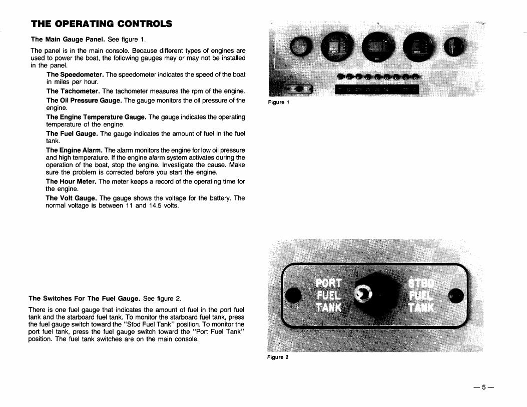
The Switches For The Fuel Gauge. See figure 2.
There is one fuel gauge that indicates the amount of fuel in the port fuel tank and the starboard fuel tank. To monitor the starboard fuel tank, press the fuel gauge switch toward the "Stbd Fuel Tank" position. To monitor the port fuel tank, press the fuel gauge switch toward the "Port Fuel Tank" position. The fuel tank switches are on the main console.
Figure 2
-5

The Helm. See figure 5.
The helm is on the main console below the accessory panel. The helm controls the direction of the boat.
Figure 5
The Battery Main Switches. See figure 6.
There are two battery main switches. One switch is in the aft port side of the bilge area. The other switch is in the aft starboard side of the bilge area. To get access to the switches, lift the aft transom hatch. The switch controls the 12-volt electrical system of the boat. To activate the system, the "Battery Main" switches must be in the "On" position.
Figure 6
-7

The Shore Power Connection Inlet. See figure 9.
The inlet is on the starboard side of the boat below the windshield. The breaker that protects the inlet is on the AC breaker panel in the cabin.
Figure 9
The City Water Inlet/Pressure Regulator. See figure 10.
The inlet permits the boat to be connected to city water pressure when at dock. The city water inlet/pressure regulator is in the side shield forward of the power inlet.
CAUTION: To prevent water damage and/or sinking,A disconnect the dockside water pressure whenever the boat is left unattended. Rust particles or other foreign objects in the line from the shore can cause malfunctioning of the regulator.
Figure 10
The Trim Tab Switch Option. See figure 11.
The trim tab switches control the level ride of the boat. The trim tab switches are on the starboard side of the helm.
The left rocker switch (1) controls the lowering and raising of the port bow. To raise the port bow, push the lower part of the rocker switch. To lower the port bow, push the upper part of the rocker switch.
The right rocker switch (2) controls the lowering and raising of the starboard bow. To raise the starboard bow, push the lower part of the rocker switch. To lower the bow, push the upper part of the rocker switch.
The breaker that protects the trim tab switches is on the breaker panel that protects the accessory switches.
Figure 11 -9

The AC And DC Main Breaker Panels. See figure 14.
The panel for the AC system and the DC system are on the starboard side of the main cabin.
The DC Electrical System gets its power from the boat's batteries. To activate the boat's 12-volt system, the "Battery Main" switches must be in the "On" position. The "Battery Main" switches are on the bulkhead in front of the hot water heater. The 12-volt system protects the lighting system, the instrumentation system and the utilities.
The source of power for the AC electrical system comes from a shoreline connection.
NOTE: Connect the shore cord to the shoreline outlet before the 110-volt main switch in the boat is activated.
To activate the boat's 11Q-volt system, put the main switch (1) for the 11Q-volt system in the "On" position. The 110-volt system protects all outlets, the refrigerator, the stove, the water heater, the battery charger and the air conditioner.
NOTE: The refrigerator will run on either the 12-volt battery system or the 11 O-volt system. If both systems are activated, the refrigerator will operate on the 110-volt system.
The Polarity Indicator Light (2) is below the main switch for the 11 O-volt system. If the green light illuminates, the AC system is safe for operation. Do not activate the "AC Main" switch if the red light illuminates. The red light is a warning of trouble. Investigate the cause immediately.
Figure 14
-11

How To Fill The Fresh Water Tank
The fill cap to the fresh water tank is in the starboard side of the transom. See figure 17.
Figure 17
To fill the tank, follow this procedure:
1. A special key to unlock the fill cap is given to you. Insert the key in the slot in the cap.
2. Turn the key counterclockwise to unlock the cap.
3. Remove the cap.
4. Fill the tank with clean fresh water.
NOTE: The water tank is full when the water comes out of the water vent. The water vent is in the starboard side of the transom above the water fill cap. See figure 18.
5. Put the cap in position.
6. Turn the key clockwise to lock the water cap in position.
NOTE: The water pressure pump is a demand type pump. If the fresh water tank is empty and the breaker switch for the pump is in the "On" position, the pump will continue to run. Make sure the breaker switch is in the "Off" position when there is no water in the tank.
How To Fill The Baitwell With Water
The "Baitwell" switch is on the accessory panel.
NOTE: A manual valve that allows new water to circulate in the baitwell is in the upper part of the well. See figure 19.
Figure 19
To fill the baitwell with water, follow this procedure:
1. Open the valve. The valve is open when the lever is in-line with the fill tube.
2. Put the switch on the accessory panel in the "On" position.
NOTE: When the water reaches the level above the filter, the extra water will drain from the tank. New water will enter and move through the baitwell.
Figure 18
-13

A WARNING: Do not use worn or damaged cables.
WARNING: To reduce the risk of electric shock, keep all conA nections dry and off the ground. Do not touch the plug with wet hands.
WARNING: Always use a three-wire electrical system conA nected to the electrical ground. See figure 21.
[©OUTLET MUST BE CONNECTED TO THE ELECTRICAL ~ GROUND ~
- I ~ SHORE OUTLET SHIP INLET
GROU~ GROUND
PLUG TO INLETPLUG TO OUTLET
Figure 21
3. Remove the inlet cap from the inlet on the boat. To remove the cap, turn the cap counterclockwise and lift the cap.
4. Connect one end of the shore power cable to the inlet in the boat.
5. Make sure the cable has more slack than the mooring lines.
6. Remove the cap from the outlet on the pier. Connect the other end of the shore cable to the outlet on the pier.
7. Put the shore disconnect switch in the "On" position.
8. Check the polarity indicator light. The red light is a warning light. If the red light illuminates, do not activate the "AC Main" switch. Investigate the cause immediately.
9. If the green light illuminates, put the "AC Main" switch in the "On" position.
How To Disconnect The Shore Power Connection
To disconnect the shore power connection, follow this procedure:
1. Put the 110 volt "AC Main" switch in the "Off" position.
2. If there is a disconnect switch on the pier, put the disconnect switch in the "Off" position.
3. Disconnect the cable from the pier outlet. Install the cap over the outlet.
4. Disconnect the cable from the inlet in the boat. Install the cap over the inlet.
5. Put the cable in storage for future use.
To Transport The Boat On A Trailer
To transport the boat on a trailer, follow this procedure:
1. Make sure the trailer is a match for your boat's weight and hull design.
NOTE: Contact your dealer to evaluate your towing vehicle and hitch, and to make sure you have the correct trailer for your boat.
2. The Gross Vehicle Weight Rating must be shown on the trailer. Make sure the weight of the boat, engine, gear and trailer is not more than the Gross Vehicle Weight rating.
3. Make sure the boat is securely fastened on the trailer to prevent movement between the boat and trailer.
NOTE: Your dealer will give instructions on how to load, fasten and launch your boat.
WARNING: Make sure your towing vehicle and trailer are in A compliance with all state and local laws. Contact your state motor vehicle bureau for laws governing the towing of trailers.
-15
HOW TO OPERATE THE BOAT Recommended Safety Check Procedure
The following isa recommended safety check procedure for getting underway.
1. Make sure you have signal kits and flare guns aboard, and they are in good operating condition.
2. Make sure you have a complete First Aid Kit aboard.
3. Have a tool kit aboard. The kit should include the following basic tools: Spark plug wrench Hammer Spark plug gap gauge Electrician's tape Screwdriver Lubricating oil Pliers Jackknife Adjustable Wrench Vise grip Pipe Wrench
WARNING: There must be at least one personal flotation device A on-board for every person on-board and one throw-out flotation device. Check the U.S. Coast Guard standards for the correct type of device for your boat.
WARNING: Protecting persons on the boat is the owner'sA responsibility. Stop the engine before using the swim platform, or taking skiers aboard.
4. Make sure life preservers and life rings are on-board and in good condition.
5. Have the following spare parts on-board:
Extra light bulbs Spark plugs Fuses Flashlight and batteries Drain plug Engine oil Propeller Fuel filters Propeller nut and washer Fuel hose and clamps
A WARNING: Vaporizing liquid extinguishers give off toxic fumes; ~ use only Coast Guard approved fire extinguishers.
6. Make sure all fire extinguishers are in position and in good operating condition.
A CAUTION: To prevent damage to the anchor lines, mooring and .. towing lines, do not stow wet cordage in the rope locker or
below decks.
7. Make sure all lines, cables, anchors, etc. for securing a boat are onboard and in good condition. Make sure all lines are coiled, secured and off the decks when underway.
8. When you operate a boat, you accept the responsibility for the boat, for the safety of passengers and for others out enjoying the water.
Remember:
1. Alcohol severely reduces the ability to react to several different signals at once.
2. Alcohol makes it difficult to correctly judge speed and distance, or track moving objects.
3. Alcohol reduces night vision, and the ability to distinguish red from green.
Do not operate the boat while under the influence of alcohol.
To Operate The Boat
WARNING: To reduce the risk of a fire or explosion, do not start A the engines when fuel fumes are present. Fuel fumes are dangerous and harmful to your health.
WARNING: Make sure all inspection plates to the fuel tank areA open for five minutes before the engines or electrical equipment are started.
WARNING: Make sure one other person on the boat is inA structed in the operation of the boat.
WARNING: Make sure the boat is operated in compliance withA all state and local laws governing the use of a boat.
Before operating the boat for the first time, read the engine break-in procedures. The break-in procedures are found in the owner's manual for the engine. The manual is in the literature packet.
NOTE: For more instructions on safety, equipment and boat handling, enroll in one of the several free boating courses offered. For information on the courses offered in your area, call the "Boating Course Hotline", 1-800-336-2628.
-17

MAINTENANCE
L). WARNING: Do not operate the boat unless it is completely .. assembled. Keep all fasteners tight. Keep adjustments
according to specifications.
The Electrical System
Check the electrical system before each use. Make sure all switches activate the equipment they control, and all equipment is in good operating condition.
The boat has two lead acid type batteries. The starboard battery supplies power to the starboard engine and to the 30 amp main breaker on the 12-volt breaker panel. The 30 amp main breaker supplies power to the 12-volt breakers on the panel. If the output of the electric current is more than 30 amps, the main breaker will deactivate the circuit.
The port battery supplies power to the port engine, the automatic bilge pump and to the battery parallel breaker.
NOTE: The refrigerator will run on either the 12-volt battery system or the 110-volt system.
A CAUTION: To prevent the refrigerator from draining the charge .. from the batteries, put the main disconnect switches for the
batteries in the "Off" position before leaving the boat.
These maintenance procedures must be done to the batteries twice every season:
A WARNING: Lead acid batteries generate gases which can cause an explosion. NO SMOKING. Always wear eye protection and protective clothing when working near batteries. Remove all jewelry. Do not put tools or other metal objects across the battery terminals or the tops of the batteries.
A WARNING: Before doing any maintenance, make sure all .. switches are in the "Off" position.
1. Clean the batteries. To clean the batteries, follow this procedure:
1. Disconnect the batteries. 2. Use a cloth and a solution of bicarbonate of soda to wipe the tops.
3. Clean the battery terminals.
4. Reconnect the batteries.
2. Check the batteries and add distilled water as needed. The correct level is within 1/4 inch of the bottom of the tube in each cell.
The batteries are self-charging when the engine is running. If the system is used for a long period of time without the engine running, the batteries may need to be charged.
WARNING: To prevent an explosion, charge the batteries onlyA in an area with good ventilation.
CAUTION: The negative poles are grounded on the batteries. A Reverse polarity will cause damage to the alternator. When using a jumper cable or external charging, always connect the red ( +) cable to the positive terminal and the black ( - ) cable to the negative terminal of the battery.
WARNING: Lead acid batteries generate gases which can cause A an explosion. Keep sparks and flames away from the batteries.
To charge the batteries, follow this procedure:
1. Make sure the shoreline power connection is made.
2. Put the "AC Main" switch in the "On" position.
3. Put the "Battery Charger" switch in the "On" position. See figure 26.
Figure 26
Read the owner's manual for the charger for more instructions on how to use the charger and charge the batteries.
-19

A. CAUTION: To prevent damage to the engine, do not use full .. city water pressure.
4. Turn the faucet for the water supply to the half-way open position.
5. Put the control handle in the "Neutral" position.
6. Start the engine.
7. Put the control handle in the "Idle" position.
8. Let the engine run for 10 minutes or until the discharge water is clean.
9. Stop the engine.
10. Turn off the water supply.
11. Remove the garden hose from the flush-test device and the water supply outlet.
12. Remove the flush test device.
To flush the system when the boat is in the water, follow this procedure:
1. Make sure the outdrive is in the "Full Up" position.
2. Install the flush-test device over the water inlet holes in the gear housing.
3. Connect one end of a garden hose to the flush-test device.
4. Connect the other end of the garden hose to the water supply outlet.
5. Put the switch for the outdrive control in the "Down" position to lower the outdrive control all the way.
A CAUTION: To prevent damage to the engine, do not use full .. city water pressure.
6. Turn the faucet for the water supply to the half-way open position.
7. Put the control handle in the "Neutral" position.
8. Start the engine.
9. Put the control handle in the "Idle" position.
10. Let the engine run for 10 minutes or until the discharge water is clean.
11. Stop the engine.
12. Turn off the water supply.
13. Put the switch for the outdrive control in the "Up" position to raise the control.
14. Disconnect the garden hose from the flush-test device and the water outlet.
15. Remove the flush-test device.
How To Clean And Set The Spark Plugs
Clean and set the spark plugs after the first 10 hours of use and then after every 100 hours of use or every six months, whichever comes first.
A. CAUTION: Use only a wire brush and commercial solvent to .. clean the spark plugs.
To clean and set the spark plugs, follow this procedure:
1. Use a socket wrench to remove the spark plugs from the engine.
2. Use a wire brush and clean the electrodes, insulator, and threads.
3. Wash the spark plugs in a commercial solvent.
4. Use a spark plug gauge and adjust the spark plug gap to .035.
5. Use a socket wrench and install the spark plugs.
NOTE: Replacement spark plugs must be of the same heat range. Change the spark plugs after each 100 hours of use and before each season.
The Bilge Pumps
NOTE: An inline fuse protects the automatic bilge pumps. The fuse is next to the port battery main switch. See figure 28.
Figure 28
IMPORTANT: Check the fuse frequently to make sure the fuse is good. If the fuse is not good, replace the fuse.
The pumps require no lubrication. Inspect the bilge area. Make sure all connections to the pumps and thru-hull fittings are tight. Inspect the hoses. If the hoses are damaged or worn, have the hoses replaced. Make sure the float moves without restriction. Visually inspect the wiring for loose connections and damaged wires. For electrical repairs, contact a qualified electrician.
-21

How To Maintain The Exterior Surface Of The Boat
A CAUTION: Do not use abrasive cleaners on fiberglass. Abrasive .. cleaners dull the surface and will allow dirt to penetrate into
the finish.
After each use of the boat, follow this procedure:
1. Rinse the boat with clean water.
2. Use a clean sponge and a mixture of detergent and water to wash the fiberglass surfaces.
3. Use a stiff fiber brush to wash the non-skid surfaces.
4. Rinse the boat with clean water.
At least once a year, apply wax and polish the smooth gelcoat surfaces. Use a good automotive wax or a boat wax. Before applying the wax, read the directions given with the wax.
After the boat is exposed to the direct sunlight for a period of time, the color in the gelcoat tends to fade, dull or chalk. A heavier buffing is required to bring the gelcoat back to its original luster. For power cleaning, use a light cleaner such as Mirror Glaze #1. To clean the boat by hand, use a heavier automotive cleaner. Before cleaning the surfaces, read the instructions given with the cleaner. After cleaning the surfaces, apply wax and polish all fiberglass surfaces except the non-skid areas.
A pamphlet called "Congratulations Welcome To The Fiberglass Fleet" is included in the literature packet. For more information on the care of fiberglass, read the pamphlet.
If the fiberglass should become damaged and need repair, contact your dealer for an authorized repair person to make the repairs.
The exterior and interior woodwork is teak.
A. CAUTION: Do not use steel wool on the woodwork. Small par.. ticles of steel will break off the pad and damage the surface.
Only use bronze wool or sandpaper.
For longer life of the woodwork, and to maintain its color, use a teak oil on the wood surfaces. To apply the oil, read and follow the instructions given with the preservative.
The windows and hatches are made of plexiglass.
A CAUTION: Do not use chemical solvents on plexiglass. .. Solvents scratch the plexiglass and damage the window sealant
and hatch gaskets.
Use a mild soap and water, or a plexiglass cleaner to clean the windows and hatches.
How To Maintain The Interior Of The Boat
To keep the interior of the boat clean and dry, follow this procedure:
1. Clean below the decks just like you would a home interior. To preserve the woodwork, use a teak oil on all woodwork. Use a vacuum cleaner to pick up dirt in the cabin.
2. Air and sunlight are very good cleaners. Put cushions, blankets, sleeping bags, etc., up on deck in the sunshine to air and dry out.
3. If cushions or other equipment get wet with salt water, use clean fresh water to rinse off the salt crystals. Salt crystals retain moisture and will cause damage. Dry the equipment thoroughly.
4. If you leave the boat for a long period of time, put all cushions on their sides and open all lockers.
A CAUTION: Do not use chemical solvents on plexiglass. .. Solvents scratch the plexiglass and damage the window sealant
and hatch gaskets.
5. Use a mild soap and water, or a plexiglass cleaner to clean the windows.
NOTE: A cleaning kit to help maintain the exterior and interior of your boat, see figure 30, can be obtained from S2 Yachts.
Figure 30
The kit contains a: Vinyl Shampoo, Marine Polish, Hull Cleaner, Boat Wash, Vinyl Conditioner, Sponge and a white S2 Bucket.
Call 1-800-843-3172 to order the Starbrite * Kit, part number CK9880.
*Starbrite is a registered trademark of Star Brite, Inc.
-23

HOW TO PREPARE THE BOAT FOR LAY-UP
The Sanitary System
To prepare the sanitary system for lay-up, take the boat to an area where the holding tank can be pumped out.
The following is to make you aware of the procedure, but will be done by the dock master.
1. The cap to the waste deck fitting is in the covering board on the port side of the transom. See figure 31. A special key to unlock the cap is given to you. Insert the key in the slot in the cap.
Figure 31
2. Turn the key counterclockwise to unlock the cap.
3. Remove the cap.
4. Insert the pump out hose in the opening.
5. Remove all waste from the holding tank.
6. Fill the tank with clean water.
7. Remove the water from the tank.
a. Install the cap.
The Fresh Water System
The boat's fresh water system must be drained. To drain the system, follow this procedure:
1. Open all faucets throughout the boat. Do not forget the faucet in the shower.
2. Drain the water tank. To drain the water tank, follow this procedure. 1. Remove the hose at the lowest position of the water tank.
2. Let all the water drain from the hose into the bilge.
3. Activate the bilge pump to remove the water from the bilge.
3. Drain the hoses to the water supply pump. To drain the hoses and the pump, follow this procedure:
1. Remove the hose from the input side of the pump. 2. Remove the hose from the outlet side of the pump.
3. Let the water drain from the hose.
4. Start the water supply pump for a few seconds to remove the water from the bottom of the pump.
NOTE: Do not reconnect the hoses until the boat is put into commission.
The Hardware
Clean the chrome hardware. Apply a heavy coat of boat wax or a light coat of petroleum jelly on the hardware.
-25

The Batteries
To prepare the batteries for storage, follow this procedure:
1. Make sure the batteries are fully charged.
A WARNING: To prevent an explosion, charge the batteries only .. in an area with good ventilation.
2. Put the battery main switches in the "Off" position. See figure 33.
Figure 33
WARNING: Lead acid batteries generate gases which can cause A an explosion. NO SMOKING. Always wear eye protection and protective clothing when working near batteries. Remove all jewelry. Do not put tools or other metal objects across the battery terminals or the tops of the batteries.
3. Disconnect the batteries.
4. Clean the batteries.
5. Add distilled water as needed.
6. Apply a coat of petroleum jelly to the battery cable terminals.
7. Put the batteries in a dry building with good ventilation. Make sure the batteries are protected from freezing temperatures.
How To Support The Boat During Storage
Your trailer is the best support cradle for your boat during storage. Before you store the boat on a trailer for a long period of time, follow this procedure:
1. Make sure the rollers and pads support the hull of the boat.
2. Make sure the trailer hitch is level and there is support under the hitch.
3. Make sure the outdrive is in the down position.
4. Check the tires once each season. Add enough air for the correct amount of inflation for the tires.
NOTE: Read the owner's manual for the trailer for the correct amount of inflation for the tires.
Storage
Proper storage is very important to prevent serious damage to the boat. If the boat is to be stored indoors, make sure the building has enough ventilation. It is very important that there is enough ventilation both inside the boat and around the boat.
NOTE: If the boat is to be stored indoors or outdoors, open all drawers, clothes lockers, cabinets, and doors a little. If possible, remove the upholstering, mattresses, clothing, and rugs.
If the boat is to be stored outdoors and a cover is to be used, build a frame over the boat to support the canvas or plastic cover. Make sure the frame is a few inches wider than the boat so that the canvas will clear the rails. Make sure the cover is fastened securely. A loose flapping cover will damage the gelcoat surface.
-27

~
J:)0
MODEL 2650 OUTBOARD BRACKET SPECIFICATIONS
L.O.A. wlPulpit 28'10"
L.O.A. wlo Pulpit 26'5"
Beam 9'7"
Hull Draft 1'5"
Approximate Dry Weight 5,000Ibs.
Maximum Horsepower 400
Standard Fuel Capacity 234 U.S. gals.
Water Capacity 20 U.S. gals.
Holding Tank Capacity 20 U.S. gals.
Sleeping Capacity 2
Cockpit Length 9'11 "
Height Above Waterline 6'6"
-29

MODEL 2650 OUTBOARD BRACKET REPLACEMENT PARTS - EXTERIOR PROFILE 6190
Ref. No.
Code No. Description
No. Req'd
1 2 3 4 5
334133 327043 334156 543335 542123
Eye - Stern Light - Transom Vent - Water Logo - Pursuit Rubrail w/Lip
2 1 1 2
per ft.
6 7
541025 542073 549005 534616 324036
Flat Bar - Aluminum Tubing - Vinyl 3/4" Cap - Rope Gunnel 4" Handrail Inlet - Power
per ft. per ft.
1 2 1
8 535135 Regulatorllnlet - Water 1
Ref. No.
Code No. Description
No. Req'd
9 10 11 12 13
543208 334156 543347 327072 773193
Logo - S2 Vent - Fuel Logo - 2650 Light - Masthead Windshield Assembly
2 2 2 1 1
14 15 16 17 18
539291 534610 327001 534019 334025
Light - Port Bowrail Light - Side Cleat Eye - Bow
4 1 2 6 1
S2 reserves the right to make changes or improvements to its boats without notice.
-31

MODEL 2650 OUTBOARD BRACKET REPLACEMENT PARTS - EXTERIOR 6190
Ref. No.
Code No. Description
No. Req'd
1 534079 Cap - Waste Removal 1 2 334156 Vent 1
534321 Shield - S.S. 1 3 534080 Inlet - Washdown 1 4 Cap - Oil Fill ref.
5 534313 Holder - Rod 4 6 336020 Light - Courtesy 4 7 335065 Speaker - Round 2 8 773208 Locker - Port 1 9 765120 Seat w/Cooler 1
10 534596 Plate - Inspection 6" 2 11 334021 Cap - Fuel Fill 2 12 773265 Doorway Assembly ref. 13 539237 Hatch - Deck 1
539239 Screen 1
14 773250 Locker - Anchor ref. 15 765020 Bow Pulpit Option ref. 16 334110 Blade - Wiper ref.
334109 Motor - Wiper ref. 334064 Adapter ref.
334059 334062
Arm - Wiper Cover - Wiper
ref. ref.
Ref. Code No. No. No. Description Req'd
17 325017 Compass 1 18 543330 Nameplate 1 19 325327 Panel - Instrument 1 20 315031 Steering Wheel 1 21 534597 Plate - 10" Pry Up 1
22 773199 Seat ref. 23 334043 Horn 1 24 773210 Locker - Starboard ref. 25 534699 Plate - Inspection 4 26 742421 Fish Box ref.
27 773933 Tank - Circulating ref. 28 534077 Cap - Water Fill 1 29 710514 Flotation Bracket Dual w/Platform ref.
S2 reserves the right to make changes or improvements to its boats without notice.
-33

MODEL 2650 OUTBOARD BRACKET REPLACEMENT PARTS - INTERIOR 6190
Ref. No.
Code No. Description
No. Req'd
1 2 3 4 5
535299 535022 535001 535207 335064
Stove Ice Box Sink - Galley Faucet/ Pump Unit Stereo
1 1 1 1 1
6 7 8 9
336056 335066 789357 325330 325331
Light Speaker - Box Table - V-Berth Panel- AC Panel- DC
4 2 1 1 1
Ref. No.
Code No. Description
No. Req'd
10 11
12
335001 535041 535037 765054 327071
Fire Extinguisher Porta Potti Head Option Head - Electric Option Light - Fluorescent
1 1
ref. ref. 1
13 14
535004 535207
Sink - Oval Faucet/Pump Unit
1 1
S2 reserves the right to make changes or improvements to its boats without notice.
-35
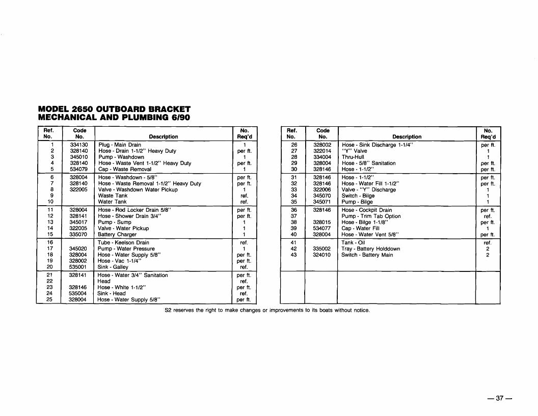
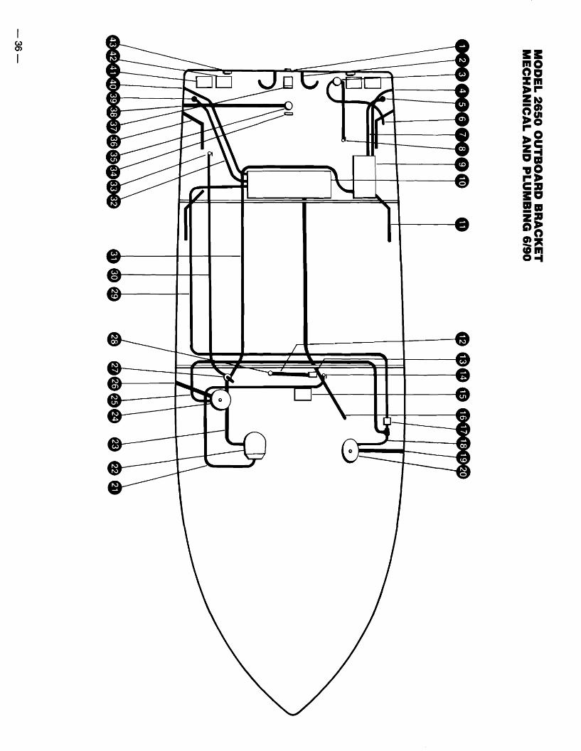
MODEL 2650 OUTBOARD BRACKET MECHANICAL AND PLUMBING 6/90
Ref. No.
Code No. Description
No. Req'd
1 334130 Plug - Main Drain 1 2 328140 Hose - Drain 1-1/2" Heavy Duty per ft. 3 345010 Pump - Washdown 1 4 328140 Hose - Waste Vent 1-1/2" Heavy Duty per ft. 5 534079 Cap - Waste Removal 1
6 328004 Hose - Washdown - 5/8" per ft. 7 328140 Hose - Waste Removal 1-1/2" Heavy Duty per ft. 8 322005 Valve - Washdown Water Pickup 1 9 Waste Tank ref.
10 Water Tank ref.
11 328004 Hose - Rod Locker Drain 5/8" per ft. 12 328141 Hose - Shower Drain 3/4" per ft. 13 345017 Pump - Sump 1 14 322005 Valve - Water Pickup 1 15 335070 Battery Charger 1
16 Tube - Keelson Drain ref. 17 345020 Pump - Water Pressure 1 18 328004 Hose - Water Supply 5/8" per ft. 19 328002 Hose - Vac 1-1/4" per ft. 20 535001 Sink - Galley ref.
21 328141 Hose - Water 3/4" Sanitation per ft. 22 Head ref. 23 328146 Hose - White 1-1/2" per ft. 24 535004 Sink - Head ref. 25 328004 Hose - Water Supply 5/8" per ft.
Ref. No.
Code No. Description
No. Req'd
26 328002 Hose - Sink Discharge 1-1/4" per ft. 27 322014 "V" Valve 1 28 334004 Thru-Hull 1 29 328004 Hose - 5/8" Sanitation per ft. 30 328146 Hose - 1-1/2" per ft.
31 328146 Hose - 1-112" per ft. 32 328146 Hose - Water Fill 1-1/2" per ft. 33 322006 Valve - "V" Discharge 1 34 345070 Switch - Bilge 1 35 345071 Pump - Bilge 1
36 328146 Hose - Cockpit Drain per ft. 37 Pump - Trim Tab Option ref. 38 328015 Hose - Bilge 1-1/8" per ft. 39 534077 Cap - Water Fill 1 40 328004 Hose - Water Vent 5/8" per ft.
41 42 43
335002 324010
Tank - Oil Tray - Battery Holddown Switch - Battery Main
ref. 2 2
S2 reserves the right to make changes or improvements to its boats without notice.
-37

MODEL 2650 OUTBOARD BRACKET LIVE BAITWELL CIRCULATING SYSTEM 6190
• I
Ref. Code No. No. No. Description Req'd
1 334015 Thru-Hull 3 2 322120 Valve - Water Pickup 1 3 345031 Pump - Aerator 1 4 328141 Hose - 3/4" Sanitation ref. 5 Fish Box ref.
6 334152 Strainer 2
Ref. Code No. No. No. Description Req'd
7 334150 Aerator Head wNalve 1 8 Baitwell Tank ref. 9 322267 Tee - 3/4 HB x 3/4 HB x 3/4 HB 1
10 345010 Pump - Water 1 11 328141 Hose - 3/4" Sanitation ref.
12 328141 Hose - 3/4" Sanitation ref.
S2 reserves the right to make changes or improvements to its boats without notice. -39

MODEL 2650 OUTBOARD BRACKET THE FUEL AND STEERING DRAWING 6190
VENT
( I. FUEL FILL
~
FILTER~I
, STEERING CYLINDER
n~
CD
PORT FUEL TANK
SHUTOFF VALVE
SENSOR
II------
~
STARBOARD FUEL TANK
~I~
1 J JL
STEERING HOSElJL \.
l I. FUEL FILL
VENT
-40

MODEL 2650 OUTBOARD BRACKET TUNA TOWER OPTION 6190
~h 52 reserves the right to make changes or improvements to its boats without notice.
253>
Ref. No.
1 2 3 4 5
6 7 8
Code No.
456090 335125 765342 456093 456092
456094 545063 535510
No. Description Req'd
Rod Holder 4 Antenna - VHF Option 1 5un Top - Folding Option 1 Elbow - Tower 1" 4 End - Halyard Eye 2
Box - Control 1 Label- Warning 1 Locker - Instrument 1
-41

MODEL 2650 OUTBOARD BRACKET THE ELECTRICAL SCHEMATIC - AC SYSTEM
UNGROUNDED CONDUCTOR (BLACK)
GROUNDED NEUTRAL CONDUCTOR (WHITE)
GROUNDED CONDUCTOR (GREEN)
! ,If"" , .i
SHORE POWER
AMMETER
~
f\
CABLE
u ~
:3 m aJ
u ~
:3 m aJ
BLACK WHITE ( h
( h
( h
{ h
OUTLETS n BLACK
WHITE STOVE
BLACK ~15'W REFRIGERATORWHITE
BLACK ......... WATER HEATERWHITE
BLACK WHITE BATTERY CHARGER
BLACK ACCESSORYWHITE
VOLTMETER I Ltt;: BLACK8 WHITE 10
( h
( h
( h ACCESSORYWHITE
':'
~ J-...... 8 WHITE
WARNING: All electrical repairs must beA performed by qualified personnel only.
-42

--
MODEL 2650 OUTBOARD BRACKET THE ELECTRICAL SCHEMATIC - DC SYSTEM
r------------------------------------------,
HOURS
VOLTS
PORT IGNITION SWITCH
20
TRIM SENSOR
r-----------------...J PORT PORT BATTERY
BATTERY SWITCH
FUEL ,
I
~----------------I
STARBOARD IGNITION SWITCH
20
II I I
STARBOARD ENGINE
TRIM SENSOR
L~_----------------------------------------J
14 GREEN 14 YELLOW
TRIM TAB14 RED20 14 BLUE
~!J 16 ORANGE/WHITE 15 ~~ 16 WHITE/REO (h
HORN
PORT WIPER10~;; (h14 BROWN/WHITE BAITWELL PUMP
~~ 16 (h PANEL LIGHTS~' BLUE
qqlJi -10-L..:'-':"''!J 0 -"" ACCESSORY
ACCESSORY~!J 0 ~16GRAY ~~ NAVIGATION/ANCHOR LIGHTS
_ 7' -=- -=- -=
10 r:-~ BROWN I~ ~~ 16 (h~ ~. ~ 14 L~ BILGE PUMP
WHITE/BLACK STARBOARD WIPER10'
~!J 14 BROWN/PINK ~ E:::h-WASH DOWN PUMP
10
qqlJi~~ 16 BLUE/YELLOW 0 COURTESY LIGHTS15
.~' ~"" ACCESSORY10 L..: '!J 0
,-, 10 RED/BROWN REFRIGERATORE:::h15 ~'!J ~
30 ,-, 14 BROWN/GREEN SHOWER SUMP PUMPE:::h
10 ~~ ~
E:::h,--, 16 ORANGE/BROWN ELECTRIC HEAD 25 ~'!J ~
~!J qq~ ACCENT LIGHTS
~' 14 BLUE/REDL..:'-.:...'!J CABIN LIGHTS
10 ~;; ,~ qqq 10- 14 BROWN/BLACK
WATER PRESSURE PUMP
~;; G:±12 REO r-h- ACCESSORY (STEREO)
WARNING: All electrical repairs must be A performed by qualified personnel only.
-43


PURSUIT;~®
S2 Yachts, Inc. 725 East 40th Street Holland, MI 49423-5392 USA (616) 392-7163 TWX 810-292-6171 © 1990 Form No. 921031 5/90

••
z o... m en

------
MODEL 2650 OUTBOARD BRACKET "Y" VALVE OPTION 6/90
Ref. Code No. No. No. Description Req'd
1 322006 Valve - Ball 1 2 328140 Hose - 1-112" White Heavy Duty per ft. 3 328056 Clamp - 1-3/4" Hose ref. 4 545005 Label - Overboard Discharge 1 5 334003 Thru-Hull - Brass 1
6 322014 "V" Valve 1 7 328140 Hose - 1-112" White Heavy Duty per ft. 8 322082 Adapter
82 reserves the right to make changes or improvements to its boats without notice.
-38
I w 0)
I

@
•••-e
I ~ I
e
•e
e .... 0

I CAl I\)
I
e,......--~..l!....-
e..•~~
••
e-e
-
11---:7/7.:....----&
II----~.

MODEL 2650 OUTBOARD BRACKET REPLACEMENT PARTS - EXTERIOR PROFILE 6/90
z=.:~?
~
.•
~~~~~~I~~~~~Ci~~i~BJ~=:cf:;; 'I u;Zlu?? u u'(u U? U un ???T \???????II??/ii?l?<c?;D __ -
PURSUIT • ~ 5> ~ Ittz z22 ? 222 2 YI!, 5";" ll:l ('???i 2U2 ?i ;;; ~
5> ":c:z:z:z:z:.m
-30

TO COMMISSION THE BOAT
A WARNING: Do not operate the boat unless it is completely .. assembled. Keep all fasteners tight. Keep adjustments
according to specifications.
To prepare the boat for commission, follow this procedure:
NOTE: It is important and recommended the fitting out procedure for the marine gear be done by a qualified service person. Read the owner's manual for the engine for the recommended procedure.
1. If the boat was stored outdoors and a cover was used, remove the cover and put it in the sun to dry. After the cover has completely dried, fold it and put it away for future use.
2. Install the battery. Make sure the battery is clean and in good condition. Add distilled water to the battery, if needed. Before activating the 12-volt system, make sure the battery is fully charged.
LIt.. WARNING: Before launching the boat, make sure the hull drain .. plug is installed.
3. Install the hull drain plug. See figure 34.
Figure 34
4. Clean the bilge area. Remove all debris from the bilge area.
5. Make sure the bilge pump and all other pumps are in good operating condition.
6. Activate the bilge blower to make sure the blower is in good operating condition.
7. Wash the boat. Apply a good quality marine wax to the fiberglass surface, all aluminum moldings and the deck hardware.
8. Use a vacuum cleaner and vacuum throughout the boat. Use a clean damp cloth and wipe the inside of the cabinets, drawers and lockers.
9. Install all upholstery, mattresses, and rugs.
10. Inspect the fire extinguisher. Make sure it is fully charged.
-28
The Bilge Area
Make sure all water is removed from the bilge area. To remove the water, follow this procedure:
A WARNING: Make sure the boat is out of the water before .. removing the hull drain plug.
1. Remove the hull drain plug. The plug is in the outside of the transom below the gimbal. See figure 32.
Figure 32
2. Pump out all water that does not drain from the compartment.
3. Use a sponge and wipe the bilge area until all water is gone.
The Engine
To prepare the engine and exhaust system for lay-up, read the owner's manual for the engine for the recommended preparation procedures.
-26

The Tuna Tower Option
WARNING: Make sure all electrical connections and repairs are A done by a licensed marine electrician.
WARNING: To reduce the risk of electrocution, and other injury A from electric shock, do not make any contact with the tuna tower during a thunderstorm.
The main components of the tuna tower are made of aluminum. Salt particles and moisture are the main cause of "white spots", pitting and corrosion of aluminum. Protective coatings such as anodizing are only an aid in the prevention of damage that can occur to the aluminum surfaces of the tower. To help prevent damage to the tower caused by salt water particles and moisture, follow this procedure:
CAUTION: To prevent serious damage to the metal surfaces, A make sure all salt water and salt particles are removed from the tuna tower after each use of the boat.
A CAUTION: To prevent damage to the tuna tower, do not use bronze wool, sandpaper, wire brushes, abrasive pads or any abrasive cleaning agents to clean anodized surfaces.
1. After each use of the boat, use clean water and a mild detergent and wash all salt water and salt particles from the tuna tower. Next, rinse the tower with clean water to make sure all detergent is removed from the aluminum surfaces. Soap allowed to dry on the surfaces will cause stains.
2. Wash all overhead surfaces, and overhead top bows with a clean damp cloth.
3. Wash the underside of the sun shade, the bows under the sun shade and all equipment with a clean damp cloth.
4. Dry all surfaces with a clean dry towel or a chamois.
5. Check the electrical equipment housing. Make sure salt has not accumulated inside or outside of the housings.
6. Wipe the salt out of the inside of the instrument boxes regularly.
7. Once a month, check the electrical grounds to make sure there is no corrosion, and all electrical fittings are tight.
8. Check all tower fittings. Make sure they are tight and in good condition.
9. At least twice a year, use a good quality grade of marine wax, and apply a coat of wax to the aluminum surfaces.
NOTE: Contact the nearest S2 authorized dealer once a year for an electrical and maintenance inspection of the tower. Use only genuine boat parts for repair.
Below The Water Line Of The Boat
When the boat is removed from the water, clean the outer bottom surface. Algae, grass, or dirt is easier to remove when alive or wet. Use a hard bristle brush to clean the surface.
A CAUTION: To prevent damage to the fiberglass, do not sand .. the outer bottom surface of the boat.
If the outer bottom surface has been painted with anti-fouling paint, contact your dealer for recommended maintenance procedures.
Service Inspection
Contact the nearest 82 authorized dealer once a year for a maintenance inspection of the boat and to make any repairs. Use only genuine boat parts for repair.
When contacting your dealer or S2 Yachts, Inc. for parts or repair, make sure you give the hull number of the boat. The hull number is in the upper starboard area of the transom.
-24

The Fresh Water System
If the water system has not been used for a long period of time and you think it may be contaminated, sanitize the system. To sanitize the water system, follow this procedure:
1. Remove the water from the fresh water tank.
2. Pour a mixture of one gallon of water and 1/4 cup of household bleach for every 15 gallons of the tank capacity into the water tank.
3. Fill the rest of the tank with fresh water.
4. Open each faucet to release all air from the water lines.
5. After all air has been released, turn off each faucet.
6. Leave the mixture in the system for three hours and then remove all liquid from the fresh water system.
7. Flush the system with potable water.
8. Fill the tank with potable water.
If after doing the above procedure, you can smell or taste the bleach mixture, follow this procedure;
1. Remove the water from the tank.
2. Mix one quart of vinegar with five gallons of water. Pour the solution into the fresh water tank.
NOTE: The motion of the boat while in use will cause the vinegar mixture to splash over the interior of the tank.
3. Leave the solution in the tank for several days.
4. Drain all liquid from the fresh water system.
5. Flush the system with potable water.
6. Fill the tank with potable water.
The Sanitary System
When the system needs to be emptied, follow this procedure:
1. Take the yacht to an area where the holding tank can be pumped out.
2. The cap to the waste deck fitting is in the covering board on the port side of the transom. See figure 29. A special key to unlock the cap is given to you. Insert the key in the slot in the cap.
Figure 29
3. Turn the key counterclockwise to unlock the cap.
4. Remove the cap.
5. Insert the pump out hose in the opening.
6. Remove all waste from the holding tank.
7. Fill the tank with clean water.
8. Remove the water from the tank.
9. Install the cap.
-22

The 110 Volt System CAUTION: Check all fittings for leaks. Check all linkage in the A steering and rudder system for corrosion, looseness, and wear. WARNING: To reduce the risk of electric shock, keep all con Make sure all connections are tight. Have all worn partsA nections dry and off the ground. Do not touch the plug with replaced. wet hands.
AA
WARNING: Always use a three-wire electrical system con Engine Lubrication nected to the electrical ground.
Check the fluids in the engine before each use of the boat.
WARNING: All electrical repairs must be done by a qualified electrician. The Engine Lube Oil
The source of power for the AC electrical system comes from a shoreline connection.
If after making a shore power connection, the polarity light illuminates red (1), do not activate the "AC Main" switch (2). See figure 27. The red light is a warning of trouble. Investigate the cause immediately.
Figure 27
The Engine
Because different types of engines are used to power the boat, read the owner's manual for the engine for more information on the engines installed in your boat.
A CAUTION: To prevent damage to the engine(s), do not operate .. the boat when the oil level mark is below the "Add" mark.
To check the oil level, remove the dipstick from the port and starboard engines. If the oil level mark is on or below the "Add" mark, add oil.
NOTE: When adding oil, make sure the oil does not pass the "Full" mark on the dipstick. Read the manual for the engine for the correct type of oil.
NOTE: To change the oil and oil filters, read the owner's manual for the engine for instructions on how to change the engine oil and filters.
The Marine Gear Fluid
Remove the dipstick from the marine gear to check the fluid level. If the fluid level mark is on or below the lower horizontal mark, add gear fluid.
NOTE: When adding gear fluid, make sure the fluid does not pass the top horizontal line on the dipstick. Read the manual for the engine for the correct type of gear fluid.
NOTE: Change the gear fluid before each season. For instructions on how to change the fluid, read the manual for the engine.
The Cooling System
If the boat is used in saltwater, flush the cooling system after each daily use.
AA A
WARNING: Before doing any maintenance, make sure the "Main Switch(es)" are in the "Off" position.
WARNING: Fuel is very flammable. NO SMOKING.
CAUTION: Check the throttle and clutch control system for wear, corrosion and loose fittings. Keep all connections clean. Make sure all fittings are tight. Have all worn parts replaced.
To flush the system when the boat is out of the water, follow this procedure:
1. Install a flush-test device over the water inlet holes on the gear housing.
NOTE: Get the flush-test device from your dealer.
2. Connect one end of a garden hose to the flush-test device.
3. Connect the other end of the garden hose to the water supply outlet.
-20

To Start The Boat
As different types of engines are used to power the boat, have the dealer describe the operating procedures for your boat. For more instructions on "How To Operate The Boat", make sure you read the instructions given to you in the owner's manual for the engine you have selected.
A WARNING: Do not operate the boat if the drive unit is damaged.
NOTE: If the drive unit hits an underwater object, stop the engine. Inspect the drive unit for damage. If the unit is damaged, contact your dealer for a complete inspection and repair of the unit.
To Stop The Boat
To stop the boat, follow this procedure:
1. Allow the engine to drop to the idle speed.
2. Make sure the shifting lever is in the neutral position.
NOTE: If the engines have been run at high speed for a long period of time, allow the engines to cool down by running the engines in the idle position for 3 to 5 minutes.
3. Turn the ignition key to the "Off" position.
4. If you are going to leave the boat for a long period of time, put the battery main switch in the "Off" position.
5. Make sure the boat is securely moored.
A CAUTION: To prevent damage to the boat, close all seacocks before leaving the boat. See figure 25. Make sure the "Auto Bilge" switch is in the "On" position.
Figure 25
-18

Do These Procedures Before Each Use Of The Boat
1. Check the fuel supply. If fuel is needed, read "How To Fill The Fuel Tank".
A WARNING: Do not operate the boat when fuel fumes are pre.. sent. Fuel fumes are dangerous and harmful to your health.
2. Check the fuel compartment for fuel leaks and fumes. Make sure all fuel lines and fittings are tight. See figure 22.
Figure 22
3. Put the battery main switches in the "On" position. See figure 23.
4. Check the engine oil level.
A CAUTION: To prevent damage to the engine, do not operate .. the boat when the oil level mark is below the "Add" mark.
To check the oil level, remove the dipstick from the engine. If the oil level mark is on or below the "Add" mark, add oil. To add oil, remove the oil filler cap. Make sure the oil does not pass the "Full" mark on the dipstick. Read the engine manual for the correct type of oil.
WARNING: Make sure the bilge pump is in good operating conA dition. Do not use the boat if the pump is malfunctioning. Replace the pump immediately.
WARNING: Large debris will clog the bilge pump and hoses A and cause switch malfunctioning.
5. Inspect the bilge area. Remove all debris from the bilge area.
6. Test all switches on the accessory panel. See figure 24. Make sure the switches activate the equipment they control, and all equipment is in good operating condition.
Figure 24
7. Put the outdrive in the full-in position.
Figure 23
-16

To remove the water from the baitwell, follow this procedure: The 110-Volt Dockside Power Option
1. Put the switch on the accessory panel in the "Off" position.
2. Put the "Live Well" switch in the "On" position.
NOTE: Check and clean the filters after each use of the baitwell.
How To Open And Close The Windshield Vent
To open the windshield vent, follow this procedure:
1. Turn the knob counterclockwise.
2. Push the knob forward.
3. Turn the knob clockwise to lock the vent in the open position.
4. To close the vent, turn the knob counterclockwise.
5. Pull the knob back until the vent is closed.
6. Turn the knob clockwise to lock the vent in the closed position.
WARNING: To reduce the risk of electrical shock, keep all conA nections dry and off the ground. Do not touch the plug with wet hands.
WARNING: Always use a three-wire electrical system conA nected to the electrical ground.
A WARNING: All electrical repairs must be done by a qualified electrician.
The source of power for the AC electrical system comes from a shoreline connection.
If after making a shore power connection, the polarity indicator illuminates red, do not activate the "AC Main" switch. See figure 20. The red light is a warning of trouble. Investigate the cause immediately.
Figure 20
How To Make A Shore Power Connection
WARNING: To reduce the risk of electrocution and other injury A from electric shock, do not make any unnecessary contact with the shore cable in wet weather. Make sure you do not make a connection to an ungrounded outlet or plug.
To make a shore power connection, follow this procedure:
1. Put the 110 volt "AC Main" switch in the "Off" position.
2. If the outlet on the pier has a disconnect switch, put the switch in the "Off" position.
-14

HOW TO PREPARE THE BOAT FOR OPERATION
The fuel system of your boat is designed to use regular or unleaded gasoline.
How To Fill The Fuel Tank
A WARNING: Fuel is very flammable. Be careful when filling the .. fuel tank. NO SMOKING. Never fill the tank while the engines,
motors, and fans are running. Fill the fuel tank in an open area.
To fill the fuel tank at a marina, follow this procedure:
1. Make sure all switches are in the "Off" position.
2. Make sure the boat is securely moored.
3. Make sure all passengers leave the boat.
4. Estimate how much fuel is needed.
NOTE: When the fuel tank is full, fuel will come out through the fuel vent. The fuel vent for the port fuel tank is on the port side of the boat. The fuel vent for the starboard fuel tank is on the starboard side of the boat. See figure 15.
NOTE: The fill caps for the fuel and water tank, and the removal cap for the waste tank are marked with either "Gas", "Diesel", "Water", or "Waste". Before adding fuel to the fuel tank, make sure the word "Gas" or "Diesel" is on the cap. Before filling the water tank with water, make sure the word "Water" is on the cap.
Figure 15
CAUTION: To prevent damage to the fuel system, use onlyA leaded or unleaded gasoline for the gasoline engine. Do not use a fuel which contains harsh additives or is an alcohol blend. Any damage done to the fuel system which is the result of use of an alcohol blend will not be covered by the S2 Warranty.
5. A special key to unlock the fuel cap is given to you. Insert the key in the slot in the fuel cap. The fuel cap for the port fuel tank is midship in the covering board on the port side of the boat. The fuel cap for the starboard fuel tank is midship in the covering board on the starboard side of the boat. See figure 16.
Figure 16
6. Turn the key counterclockwise to unlock the cap.
7. Remove the cap.
8. Put the nozzle in the fuel opening.
A. WARNING: To prevent static sparks when filling the tank, make .. sure the nozzle is in contact with the fuel opening.
9. Fill the fuel tank.
10. Remove the nozzle.
11. Install the fuel cap.
A WARNING: Make sure the fuel compartment lid is open for five .. minutes before the engine(s) or electrical equipment are
started.
A WARNING: To reduce the risk of a fire and/or explosion, do .. not start the engine(s) when fuel fumes are present. Fuel fumes
are dangerous and harmful to your health.
A. WARNING: Make sure all gasoline odors are investigated .. immediately.
12. Check the fuel compartment and below the deck for fuel odors. If you smell fuel, do not start the engine.
-12
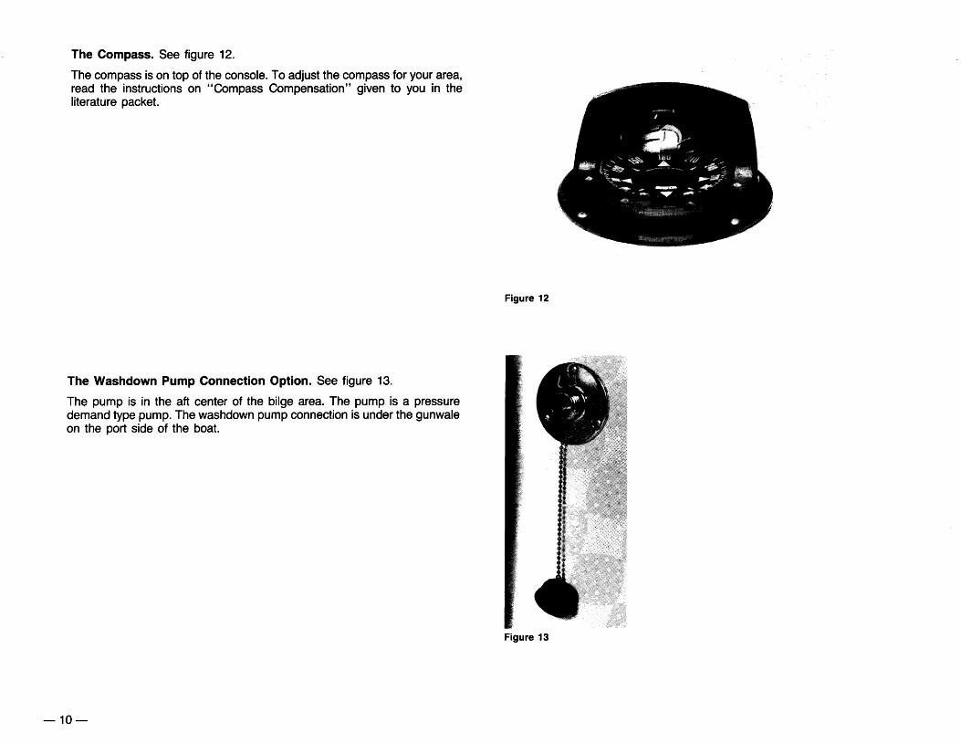
The Compass. See figure 12.
The compass is on top of the console. To adjust the compass for your area, read the instructions on "Compass Compensation" given to you in the literature packet.
Figure 12
The Washdown Pump Connection Option. See figure 13.
The pump is in the aft center of the bilge area. The pump is a pressure demand type pump. The washdown pump connection is under the gunwale on the port side of the boat.
Figure 13
-10

The Fire Extinguisher. See figure 7.
The fire extinguisher is installed in the starboard side of the cabin.
Figure 7
The Oil Tank. See figure 8.
The boat is powered by twin engines. Each engine is a two stroke engine that needs a lubricant and gasoline mixture.
The boat has two tanks that hold the lubricant. The lubricant is automatically measured into the fuel line. The tanks that hold the lubricant are inside the port and starboard transom area. There is a fill cap for each tank. The caps are in the aft port and starboard cockpit area.
For the recommended lubricant, read the manual for the engine.
Figure 8
-8

The Accessory Switch Panel. See figure 3.
The accessory switch panel is below the gauge panel. The following switches are found on the accessory panel:
The Horn Button (1). Press the button to activate the horn.
NOTE: The bilge pump will start automatically when there is water in the bilge area.
The Switch For The Bilge Pump (2). The bilge pump is installed in the center of the bilge. The pump moves water out through the thruhull fittings in the transom. To start the pump manually, put the switch in the "On" position.
h CAUTION: To prevent damage to the pump, do not operate the .. pump when there is no water in the bilge area.
The "Nav-Anchor" Light Switch (3). The switch is a three position switch. Put the switch in the "Up" position to activate the navigation lights. Put the switch in the "Down" position to activate the anchor light. The center position is the "Off" position.
The Switches For The Port And Starboard Windshield Wipers (4). To activate the wipers, put the switches in the "On" position. The wipers are offered as an option.
The Switch For The Baitwell Pump (5). To activate the pump for the live bait circulating option, put the switch in the "On" position.
The Switch For The Washdown Pump Option (6). The washdown pump is in the bilge on the port side. The pump is a pressure demand type pump. To operate the washdown pump option, put the switch for the pump in the "On" position.
The Switch For The Courtesy Lights (7). To illuminate the courtesy lights, put the switch in the "On" position.
The Switch For The Panel Lights (8). To illuminate the lights, put the switch in the "On" position.
NOTE: Each switch is protected by a breaker. The breaker panel is below the steering wheel.
The Ignition Switches. See figure 4.
The switches are on the port side of the steering wheel. The switches control the starting and stopping of the engine.
NOTE: The ignition switches shown may not be the switches installed in your boat.
-6
Figure 3
NOTE: There is a three-switch accessory panel on the starboard side of the console above the Trim Tab Option.
Figure 4

THE BOATER'S DICTIONARY
Aft: At, near or toward the stern.
Anchor Rode: Anchor rope.
Athwartship: From side to side of a boat.
Bedding: Caulking compound or application of caulking compound.
Bilge: Inside bottom of the boat's hull.
Bow: The front of the boat.
Bow Rail: A protective guard around the bow of the boat.
Bulkhead: Vertical partitions dividing the hull.
Castoff: To let loose, set free.
Chine: The outer edge of the boat where the bottom meets the side.
Cleat: Hardware to wrap the mooring line around.
Companionway: Doorway.
Cradle: A frame to support the boat while the boat is out of the water.
Deck: The portion of the boat from the gunwales up.
Fender: A cushion or pad to prevent damage to the side of the boat.
Forward: Toward the front.
Galley: The kitchen.
Gunwales: An upper edge of the hull side.
Hatch: A cover for an opening.
Head: Toilet.
Helm: The wheel by which a boat is steered.
Limber Hole: Holes through the bulkhead or stringer to allow water to pass to the pump.
Lay-Up: To put in storage.
-4
Marine Gear: The transmission.
Moored: To keep a boat in place by means of a rope or anchor.
Porthole: An opening in the side of the boat to let in air and light.
Portside: The left side of a boat when facing the bow.
Prop: Propeller.
Rubrail: A protective guard on the gunwale of a boat.
Rudder: A hinged flat piece at the rear end of the boat that directs the boat.
Scupper: An opening in the hull of a boat to let water run off the cockpit floor.
Seacock: A valve on any underwater thru-hull.
Starboard: The right side of a boat when facing forward.
Shaft Log: A tube through which the prop shaft passes through the bottom of the boat.
Slings: Straps by which the boat is lifted.
Stern: The hind part of a boat.
Strake: A rib on the bottom side of the hull running fore and aft.
Stringer: A support member inside the hull.
Strut: The metal casting bolted to the bottom of the hull to support the cutlass bearing for the propeller shaft.
Stuffing Box: A chamber through which the propeller shaft passes.
Taffrails: The rails around the stern of the boat.
Thru-Hulls: A fitting through the hull of the boat.
Thru-Hull Strainer: A filter attached to the thru-hull fitting.
Transom: The vertical portion of the hull at the back of the boat.
Underwater Gear: Any component that is fastened to the outside of the hull under water.

s ~®
Dear Pursuit® Owner:
All of us at S2 Yachts are pleased that you have selected one of our Pursuits as your boat. As I'm sure you've discovered during the selection and decision process, your Pursuit® has been designed, engineered and built with care and precision.
Please allow me to note this personal philosophy. When I started this company, my goal was to provide you, our customer, with the finest quality boat available. Everything we have achieved since that time has been with that same goal in mind.
The information in this owner's manual has been assembled to assist you with your Pursuit for maximum enjoyment. Please read this manual completely and always operate your boat safely and courteously.
Thank you for selecting a Pursuit. We all wish you many years of boating fun and safety.
Sincerely,
~Uf~ Leon R. Slikkers Chief Executive Officer
-2