Embed Size (px)
Citation preview
By Authority OfTHE UNITED STATES OF AMERICA
Legally Binding Document
By the Authority Vested By Part 5 of the United States Code § 552(a) and Part 1 of the Code of Regulations § 51 the attached document has been duly INCORPORATED BY REFERENCE and shall be considered legally binding upon all citizens and residents of the United States of America. HEED THIS NOTICE: Criminal penalties may apply for noncompliance.
Official Incorporator:THE EXECUTIVE DIRECTOROFFICE OF THE FEDERAL REGISTERWASHINGTON, D.C.
Document Name:
CFR Section(s):
Standards Body:
e

H-33(10) 7-21-89
H-33 DIESEL FUEL SYSTEMS
Based on ABYC's assessment of the state of existing technology and the problems associated with achieving the requirements of this standard, ABYC recommends compliance with this standard by August 1, 1990.
H-33.1. PURPOSE
These recommended practices and engineering standards establish requirements for the design, choice of materials for, construction and installation of permanently installed diesel fuel systems.
H-33.2. SCOPE
These recommended practices and engineering standards apply to all parts of permanently installed diesel fuel systems on boats to the point(s) of connection at the propulsion engine(s) or auxiliary equipment.
H-33.3. DEFINITIONS
a. Accessible - Capable of being reached for inspection, removal or maintenance without removal of permanent boat structure.
b. Pennanent/y Installed - Securely fastened so that tools such as wrenches and screwdrivers must be used for removal.
c. Static Floating Position - The attitude in which a boat floats in calm water, with each fuel tank filled to its rated capacity, but with no person or item of portable equipment on board. Other tanks such as water, holding, and live bait well tanks are to be empty. Factory supplied permanently attached non-portable equipment is to be on board the boat.
H-33.4. REFERENCES
a. ASTM - American Society for Testing and Materials. The referenced standards may be obtained from the American Society for Testing and Materials, 1916 Race Street, Philadelphia, PA 19103.
b. Military Specification - A specification developed by the u.S. Armed Forces. The referenced specifications may be obtained from the Naval Publications and Forms Center, 5801 Tabor Avenue, Philadelphia, PA 19120.
c. SAE - Society of Automotive Engineers. The referenced standards may be obtained from the Society of Automotive Engineers, 400 Commonwealth Drive, Warrendale, P A 15096.
d. UL - Underwriters Laboratories, Inc. The referenced standards may be obtained from Underwriters Laboratories, Inc., 12 Laboratory Drive, P.O. Box 13995, Research Triangle Park, NC 27709.
© 1990 American Boat and Yacht Council, Inc.
1
H-33(10) 7-21-89
H-33.S. REQUIREMENTS IN GENERAL
In order to attain the highest practical degree of freedom from fuel or vapor leakage within the hull, all parts of the system shall comply with the following:
a. All component parts of the fuel system shall comply with the applicable sections of this standard and shall be so documented.
b. The entire system shall be liquid and vapor tight to the hull interior.
c. The system shall be permanently installed and all component parts shall be independently supported.
d. All components of the system shall be accessible (see ABYC H-33.7.d.).
EXCEPTION: Fuel tanks.
e. Individual components of the system, and the system as a whole, shall be designed to withstand the combined conditions of pressure, vibration, shock, and movement encountered under normal operating conditions.
f. Components of the system and the fuel distribution system shall be designed and sized to provide the required fuel flow to the engine at the maximum power setting of the engine.
g. All individual components of the fuel system as installed in the boat shall be capable of withstanding a 2 1/2 minute exposure to free burning fuel (N-Heptane) or No.2 Diesel Fuel without leakage.
EXCEPTION 1. Portions of fuel distribution systems, if a break at any point in this system will result in the discharge of no more than 5 ounces of fuel in 2 1/2 minutes including fuel that may drain from the engine. See ABYC H-33.10.c. which precludes the use of non-fire resistant hose for fuel retum lines.
EXCEPTION 2. Self-draining fill and vent pipes located in a separate compartment from the engine compartment.
EXCEPTION 3. Fill and vent extemal fittings.
h. Fuel tanks shall be capable of withstanding mechanical strength tests as described in ABYC H· 33.9.
1. The system and all components shall be capable of operation within an ambient temperature range of from _29° C (-20°F) to 80° C (176° F) without failure or leakage.
j. Drain valves on the filter(s) and fuel tank(s) shall be of the type which cannot be opened inadvertently, or shall be installed in a manner to guard against inadvertent opening. All other outlets for draining fuel from the system are prohibited.
© 1990 American Boat and Yacht Council, Inc.
2
(H-33.5.)
H-33(10) 7-21-89
k. Each metal or metallic plated component of the fuel fill system and fuel tank, which is in contact with the fuel must be grounded so that its resistance to the boat's ground is less than one ohm. Bonding wire ends shall not be clamped between the fill pipes and the flexible tubing.
1. Each tank shall be tested prior to installation to the maximum pressure indicated on the tank label. (See ABYC H-33.7.b.(I) and H-33.7.c.(2)(f). The fuel tank shall evidence no leakage under such testing.
m. After installation, the fuel system of every boat shall be pressure checked to at least 3 psi or at 1 1/2 times the maximum hydrostatic head to which it may be subjected in service, whichever is greater. The fuel system shall evidence no leakage under such testing, checked at a minimum of 5 minutes after application of the test pressure, for systems of 50 or less gallons capacity, with one additional minute for each increment of 10 gallons, or fraction thereof, from 50 to 500 gallons. On tanks over 500 gallons test for 50 minutes plus 1/2 minute for each increment of 10 gallons over 500 gallons. A leak detection method other than the pressure drop method must be used at every joint except at the deck fill and exterior vent fittings.
NOTE: It is suggested that soapy test solutions be nOIl-co17-osive and nOll-toxic. Ammonia, which is present ill some soaps and detergents, creates a condition which attacks brass fittings like those used in fuel systems. Undetectable at first, in a matter of months these fittings may develop cracks.
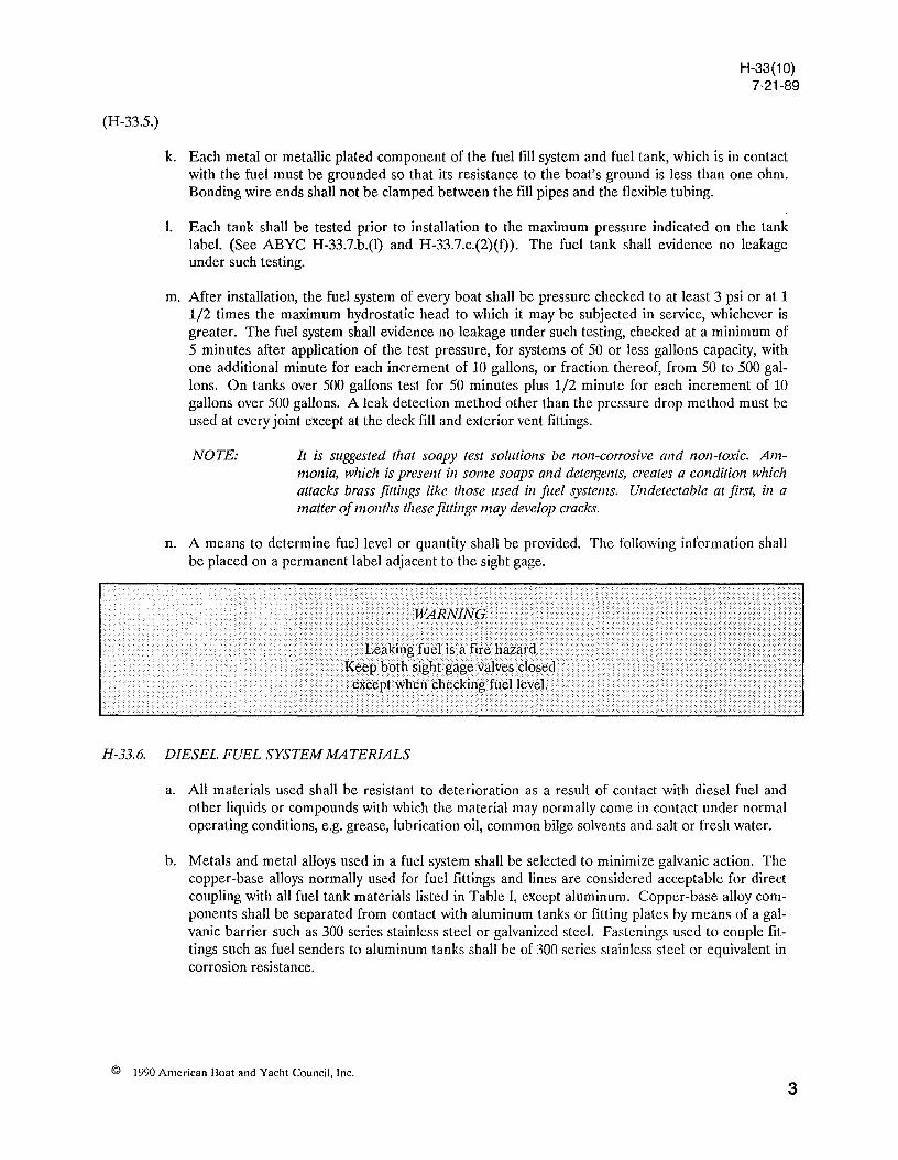
n. A means to determine fuel level or quantity shall be provided. The following information shall be placed on a permanent label adjacent to the sight gage.
H-33.6. DIESEL FUEL SYSTEM MATERIALS
a. All materials used shall be resistant to deterioration as a result of contact with diesel fuel and other liquids or compounds with which the material may normally come in contact under normal operating conditions, e.g. grease, lubrication oil, common bilge solvents and salt or fresh water.
b. Metals and metal alloys used in a fuel system shall be selected to minimize galvanic action. The copper-base alloys normally used for fuel fittings and lines are considered acceptable for direct coupling with all fuel tank materials listed in Table I, except aluminum. Copper-base alloy components shall be separated from contact with aluminum tanks or fitting plates by means of a galvanic barrier such as 300 series stainless steel or galvanized steel. Fastenings used to couple fittings such as fuel senders to aluminum tanks shall be of 300 series stainless steel or equivalent in corrosion resistance.
© 1990 American Doat and Yacht Council, Inc.
3
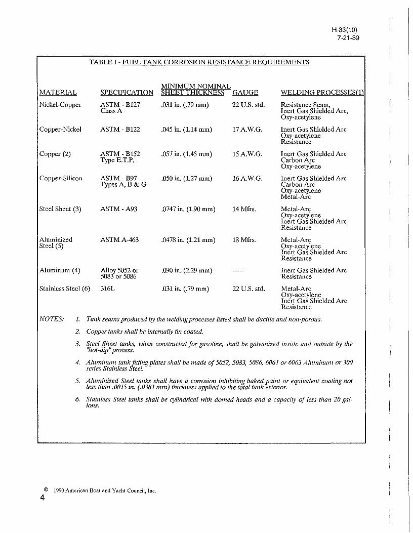
TABLE 1- FUEL TANK CORROSION RESISTANCE REQUIREMENTS
H-33(10) 7-21-89
MATERIAL MINIMUM NOMINAL
SPECIFICATION SHEET THICKNESS GAUGE WELDING PROCESSES(l)
Nickel-Copper ASTM-B127 Class A
.031 in. (.79 mm) 22 U.S. std. Resistance Seam, Inert Gas Shielded Are, Oxy-acetylene
Copper-Nickel ASTM-B122 .045 in. (1.14 mm) 17 AW.G. Inert Gas Shielded Arc Oxy-acetylene Resistance
Copper (2) ASTM- B152 Type E.T.P.
.057 in. (1.45 mm) 15 AW.G. Inert Gas Shielded Arc Carbon Arc Oxy-acetylene
Copper-Silicon ASTM - B97 TypesA,B & G
.050 in. (1.27 mm) 16 AW.G. Inert Gas Shielded Arc Carbon Arc Oxy-acetylene Metal-Arc
Steel Sheet (3) ASTM-A93 .0747 in. (1.90 mm) 14 Mfrs. Metal-Arc Oxy-acetylene
Aluminized ASTMA-463 .0478 in. (1.21 mm) Steel (5)
18 Mfrs.
Inert Gas Shielded Arc Resistance
Metal-Arc Oxy·acetylene Inert Gas Shielded Arc Resistance
Aluminum (4) Alloy 5052 or 5083 or 5086
.090 in. (2.29 mm) Inert Gas Shielded Arc Resistance
Stainless Steel (6) 316L .031 in. (.79 mm) 22 U.S. std. Metal-Arc Oxy-acetylene Inert Gas Shielded Arc Resistance
NOTES: 1. Tank seams produced by the welding processes listed shall be ductile and non-porous.
2. Copper tanks shall be intemally tin coated.
3. Steel Sheet tanks, when constmcted for gasoline, shall be galvanized inside and outside by the "hot -dip" process.
4. Aluminum tank fitting plates shall be made of 5052, 5083, 5086, 6061 or 6063 Aluminum or 300 series Stainless Steel.
5. Aluminized Steel tanks shall have a corrosion inhibiting baked paint or equivalent coating not less than .0015 in. (.0381 mm) thickness applied to the total tank exterior.
6. Stainless Steel tanks shall be cylindrical with domed heads and a capacity of less than 20 gallons.
© 1990 American Boat and Yacht Council, Inc.
4
H-33(10) 7-21-89
H-.J3. 7. DIESEL FUEL TANKS
a. Materials
(1) Material thickness shall be at least the minimum thickness listed in Table 1. Materials not listed in Table I shall be tested in accordance with ASTM Bll7, "Salt Spray (Fog) Testing", to the extent of demonstrating corrosion resistance equivalency to those materials listed.
(2) Fuel tanks shall not be constructed of terneplate steel.
(3) Non-metallic materials, e.g. fiberglass, are considered acceptable for corrosion resistance, however, all other requirements of this standard must be met.
b. Design and Constrnctioll
(1) The test pressure (see ABYC H-33.7.c.(2)(f) shall not be less than 3 psi.
(2) The tank design shall be such that no exterior metallic part of the tank will trap water as the tank is intended to be installed when the boat is in the static floating position.
(3) The exterior shape of the tanks shaH provide smooth bearing surfaces to support and secure the tank.
(4) If baffles are provided, the total open area provided in the baffles shall be a maximum of 30 percent of the tank cross section in the plane of the baffle. Baffle openings shall be designed so that they do not prevent the fuel flow across the bottom or trap vapor across the top of the tank.
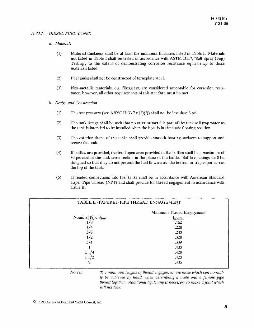
(5) Threaded connections into fuel tanks shall be in accordance with American Standard Taper Pipe Thread (NPT) and shall provide for thread engagement in accordance with Table II.
TABLE II -TAPERED PIPE THREAD ENGAGEMENT
Minimum Thread Engagement Nominal Pipe Size
1/8 Inches
.162
.228
.240
.320
.339
.400
.420
.420
.436
NOTE:
1/4 3/8 1/2 3/4
1 11/4 11/2
2
TIle minimum lengths of thread engagement are those which can nonnal· ly be achieved by hand, when assembling a male and a female pipe thread together. Additional tightening is necessmy to make a joint which will not leak.
© 1990 American Boat and Yacht Council, Inc.
5
H-33(10) 7-21-89
(H-33.7.b.)
(6) Rigid tubes and flll pipes which extend near the tank bottom shall have clearance to prevent contact with the bottom due to flexing of the tank.
(7) If the fuel pick-up tube and/or return tube is not furnished as part of the tank, the tank manufacturer shall provide a detailed construction print of the installation.
c. Labeling
(1) The following information shall be placed on a permanent label in a readily visible location on the boat or at a point of frequent servicing of the boat.
(2) All fuel tanks shall bear a label with at least the following information:
(a) Manufacturer's name or trademark and address.
(b) Month (or lot number) and year of manufacture.
(c) Capacity
(d) Material specification and thickness.
( e) Fuel for which tank is suitable or manufactured.
(f) Maximum test pressure.
(g) Model designation.
d. Installation - Unless specifically designed for the purpose, non-integral fuel tanks shall be installed in such a manner that they do not support decks, bulkheads or other structure.
(1) Diesel or heavier fuel oil tanks may be integral with the hull. If reinforced plastic laminated core construction is used where the hull is integral with the tank, the core material shall not deteriorate from contact with diesel fuel and shall not permit fuel to migrate.
(2) Fuel tanks not encased in plastic shall be installed in a manner that will permit inspection and testing.
(a) The connections, fittings and labels must be accessible, and
© 1990 American Boat and Yacht Council, Inc.
6
(H -33.7.d.(2»
H-33(10) 7-21-89
(b) The tank(s) shall be installed in such a manner that means for maintenance or replacement is provided or indicated so it can be accomplished with a minimum disturbance to the boat structure.
EXCEPTION: 77zennoset fiberglass reinforced plastic filel tanks.
(3) If a non-metallic fuel tank is encased in plastic foam ( cellular plastic),
(a) the connections, fittings and labels must be accessible, and
(b) the fuel tank must be supported in the boat by means other than the plastic foam.
EXCEPTION: Installations using foam that meets the applicable requirements of ABYC H-33. 7.d. (4)( e) do not require other support means.
(4) If a metallic fuel tank is encased in plastic,
(a) the connections, fittings and labels must be accessible,
(b) the tank material may not be a ferrous alloy,
(c) the plastic must be attached to the metal surface of the tank so as to prevent moisture between the metal and the plastic,
(d) the adhesive strength of the metal to plastic bond must exceed the cohesive strength of the plastic, and
( e) the cellular plastic used to encase fuel tanks must:
(i) not change volume by more than five percent or dissolve after being immersed in any of the following liquids for 24 hours at 29 0 C(84.2 0 F).
- No.2 Reference Oil of ASTM D-471.
~ Five percent solution of trisodium phosphate in water.
(ii) Not absorb more than 0.12 pound of water per square foot of cut surface measured under Military Specification MIL P-21929B, dated June 22, 1970.
(iii) Non-polyurethane cellular plastic, if used to encase fuel tanks, must have a compressive strength of at least 60 pounds per square inch at ten percent deflection measured under ASTM D-1621, "Compressive Strength of Rigid Cellular Plastics".
© 1990 American Boat and Yacht Council, Inc.
7
H-33(10) 7-21-89
(H-33.7.d.( 4).( e))
(iv) Polyurethane cellular plastic, if used to encase fuel, must have a density of at least 2.0 pounds per cubic foot, measured under ASTM 0-1622, "Apparent Density of Rigid Cellular Plastics".
(5) Each metallic tank must be installed to allow drainage of accumulated water from the tank's surfaces when the boat is in its static floating position.
(6) Fuel tanks shall be installed and restrained to provide as close to no movement as is possible.
(7) All non-integral tank supports, chocks or hangers shall be separated from the tank surface by a non-metallic non-moisture-absorbant, non-abrasive material suitable for the purpose. (e.g. neoprene, teflon and high density plastics.) Metallic fuel tanks installed above flat surfaces shall be separated from the surfaces by at least 1/4 inch air space when filled with fuel.
(8) Unless specifically designed for such exposure, non-integral metal tanks shall be installed where they cannot be reached by normal accumulation of bilge water.
H-33.8. NON-INTEGRAL DIESEL FUEL TANK TESI1NG FOR FIRE RESISTANCE
a. Representative samples of the fuel tanks shall be subjected to the test described herein. The tank to be tested shall be a complete assembly and include the fuel pick-up tube, fuel return tube, fuel-fill pipe and fuel gauge specified for the fuel tank.
b. A single fuel tank design, shown to be fully representative of a series of fuel tanks of similar design, size and construction, may be tested as representative of that series of fuel tanks.
c. A fuel tank shall be capable of withstanding exposure to a test fire without contributing to the fire due to leakage of the fuel contained therein. For the purpose of this test, slight vapor leakage will be permitted except in the tank shell, if it can be shown that the path of leakage will not permit a fire outside the tank to ignite vapors within the tank.
d. The fuel tank sample to be tested is to be provided with all the attachments specified by the manufacturer.
(1) As-Installed Fire Test
(a) This test shall be conducted to qualify fuel tanks intended to be installed in a particular model boat or series of boats where the construction of the tank is known and the installation of the tank is specified or otherwise controlled.
(b) The fuel tank sample shall be installed in an actual or simulated hull section of sufficient size to simulate fire conditions aboard the boat. All bulkheads, supports, floors and other surfaces in the simulated fuel tank compartment shall be of the same material or of equivalent flammability to that used on the boat.
© 1990 American Boat and Yacht Council, Inc.
S
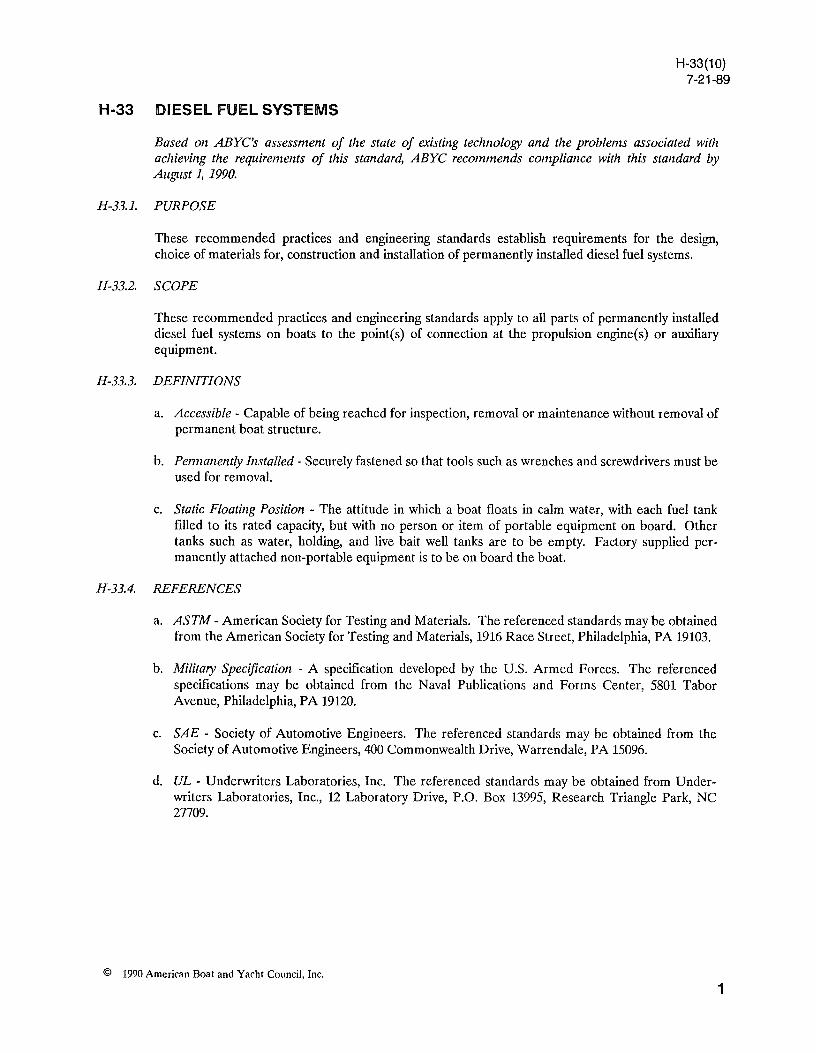
Hull Deck
V.nt ....... ===\
Fuel Tanlc
FIGURE 2 ENCLOSURE-ABOVE DECK
INSTALLA nON
© 1990 American Boat and Yacht Council, Inc.
Deck
Strap.
H-33(10) 7-21-89
FIGURE 1 ENCLOSURE-BELOW DECK
INSTALLATION
Straptl
Vent
"'"II--I---Bottom Support
9
(H-33.8.d.(I»
H-33(10) 7-21-89
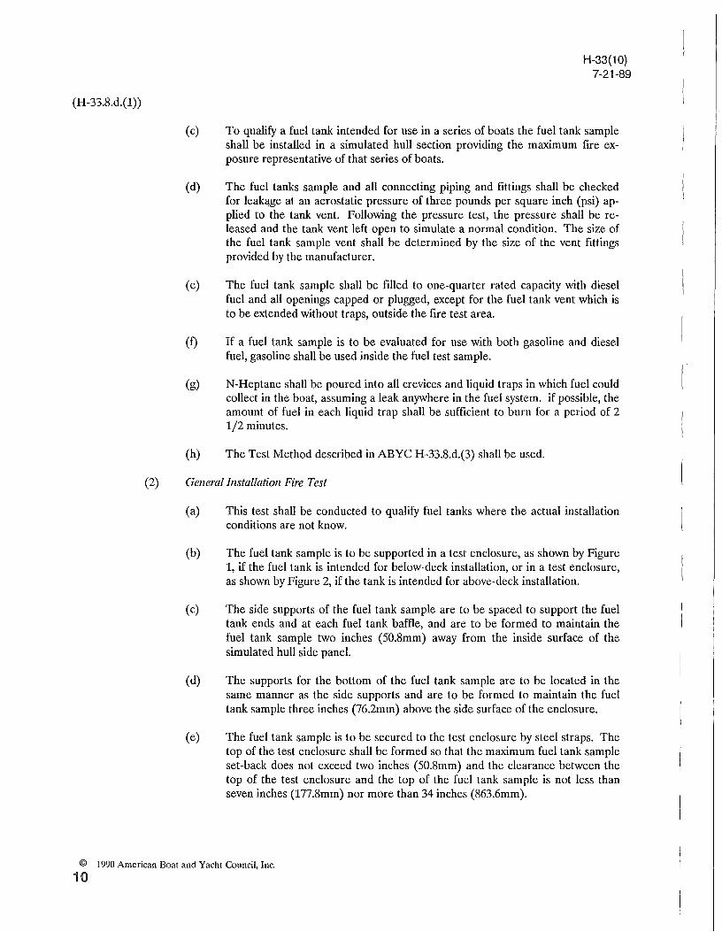
(c) To qualify a fuel tank intended for use in a series of boats the fuel tank sample shall be installed in a simulated hull section providing the maximum fire exposure representative of that series of boats.
(d) The fuel tanks sample and all connecting piping and fittings shall be checked for leakage at an aerostatic pressure of three pounds per square inch (psi) applied to the tank vent. Following the pressure test, the pressure shall be released and the tank vent left open to simulate a normal condition. The size of the fuel tank sample vent shall be determined by the size of the vent fittings provided by the manufacturer.
(e) The fuel tank sample shall be filled to one-quarter rated capacity with diesel fuel and all openings capped or plugged, except for the fuel tank vent which is to be extended without traps, outside the fire test area.
(f) If a fuel tank sample is to be evaluated for use with both gasoline and diesel fuel, gasoline shall be used inside the fuel test sample.
(g) N-Heptane shall be poured into all crevices and liquid traps in which fuel could collect in the boat, assuming a leak anywhere in the fuel system. if possible, the amount of fuel in each liquid trap shall be sufficient to burn for a period of 2 1/2 minutes.
(h) The Test Method described in ABYC H-33.8.d.(3) shall be used.
(2) General Installation Fire Test
(a) This test shall be conducted to qualify fuel tanks where the actual installation conditions are not know.
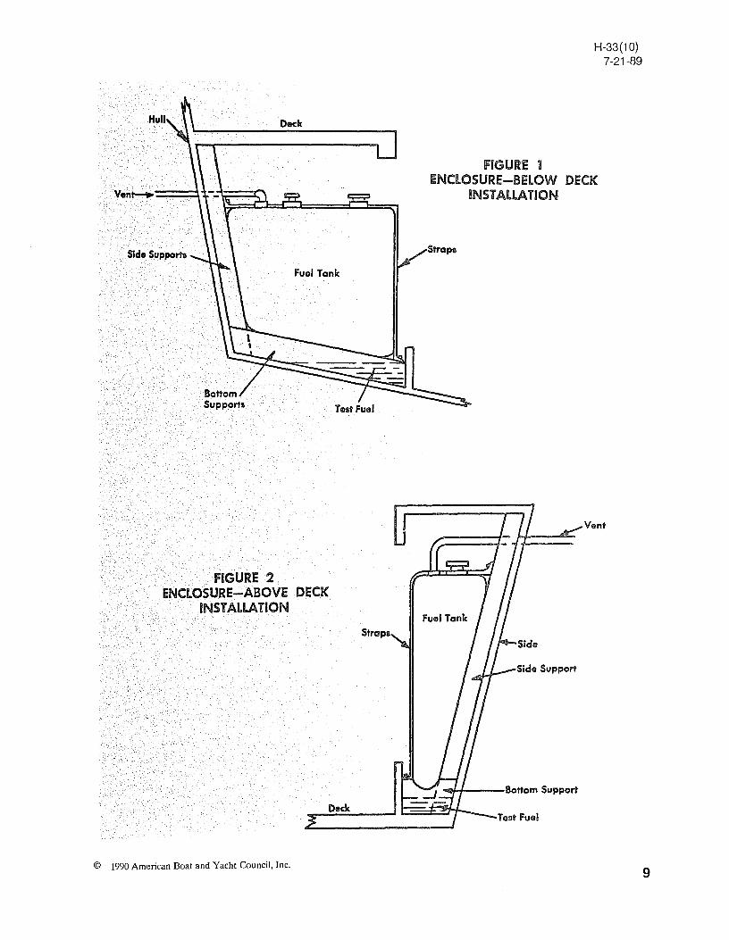
(b) The fuel tank sample is to be supported in a test enclosure, as shown by Figure 1, if the fuel tank is intended for below-deck installation, or in a test enclosure, as shown by Figure 2, if the tank is intended for above-deck installation.
(c) The side supports of the fuel tank sample are to be spaced to support the fuel tank ends and at each fuel tank baffle, and are to be formed to maintain the fuel tank sample two inches (50.8mm) away from the inside surface of the simulated hull side panel.
(d) The supports for the bottom of the fuel tank sample are to be located in the same manner as the side supports and are to be formed to maintain the fuel tank sample three inches (76.2mm) above the side surface of the enclosure.
(e) The fuel tank sample is to be secured to the test enclosure by steel straps. The top of the test enclosure shall be formed so that the maximum fuel tank sample set-back does not exceed two inches (50.8mm) and the clearance between the top of the test enclosure and the top of the fuel tank sample is not less than seven inches (177.8mm) nor more than 34 inches (863.6mm).
© 1990 American Boat and Yacht Council, Inc.
10
(H -33.8.d.(2»
H-33(10) 7-21-89
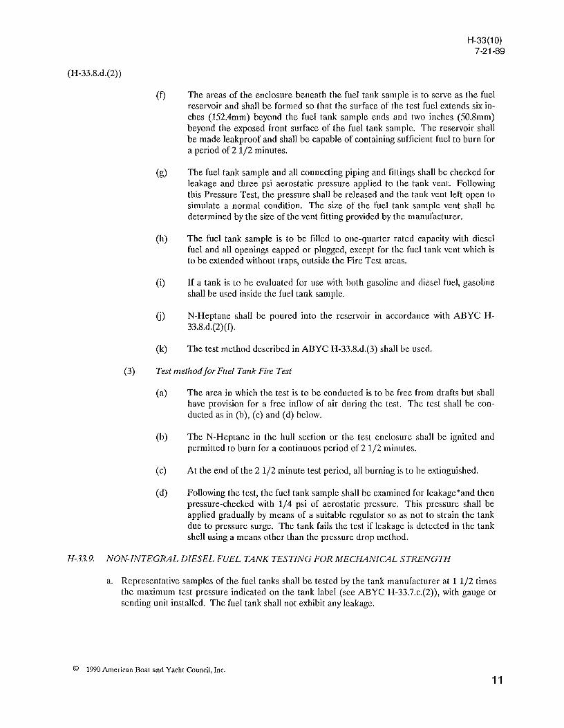
(f) The areas of the enclosure beneath the fuel tank sample is to serve as the fuel reservoir and shall be formed so that the surface of the test fuel extends six inches (152.4mm) beyond the fuel tank sample ends and two inches (50.8mm) beyond the exposed front surface of the fuel tank sample. The reservoir shall be made leakproof and shall be capable of containing sufficient fuel to burn for a period of 2 1/2 minutes.
(g) The fuel tank sample and all connecting piping and fittings shall be checked for leakage and three psi aerostatic pressure applied to the tank vent. Following this Pressure Test, the pressure shall be released and the tank vent left open to simulate a normal condition. The size of the fuel tank sample vent shall be determined by the size of the vent fitting provided by the manufacturer.
(h) The fuel tank sample is to be filled to one-quarter rated capacity with diesel fuel and all openings capped or plugged, except for the fuel tank vent which is to be extended without traps, outside the Fire Test areas.
(i) If a tank is to be evaluated for use with both gasoline and diesel fuel, gasoline shall be used inside the fuel tank sample.
G) N-Heptane shall be poured into the reservoir in accordance with ABYC H-33.8.d.(2)(f).
(k) The test method described in ABYC H-33.8.d.(3) shall be used.
(3) Test method for Fuel Tank Fire Test
(a) The area in which the test is to be conducted is to be free from drafts but shall have provision for a free inflow of air during the test. The test shall be conducted as in (b), ( c) and (d) below.
(b) The N-Heptane in the hull section or the test enclosure shall be ignited and permitted to burn for a continuous period of 2 1/2 minutes.
(c) At the end of the 2 1/2 minute test period, all burning is to be extinguished.
(d) Following the test, the fuel tank sample shall be examined for leakage*and then pressure-checked with 1/4 psi of aerostatic pressure. This pressure shall be applied gradually by means of a suitable regulator so as not to strain the tank due to pressure surge. The tank fails the test if leakage is detected in the tank shell using a means other than the pressure drop method.
H-33.9. NON-INTEGRAL DIESEL FUEL TANK TESTING FOR MECHANICAL STRENGTH
a. Representative samples of the fuel tanks shall be tested by the tank manufacturer at 1 1/2 times the maximum test pressure indicated on the tank label (see ABYC H-33.7.c.(2», with gauge or sending unit installed. The fuel tank shall not exhibit any leakage.
© 1990 American Boat and Yacht Council, Inc.
11
(H-33.9)
H-33(10) 7-·21-89
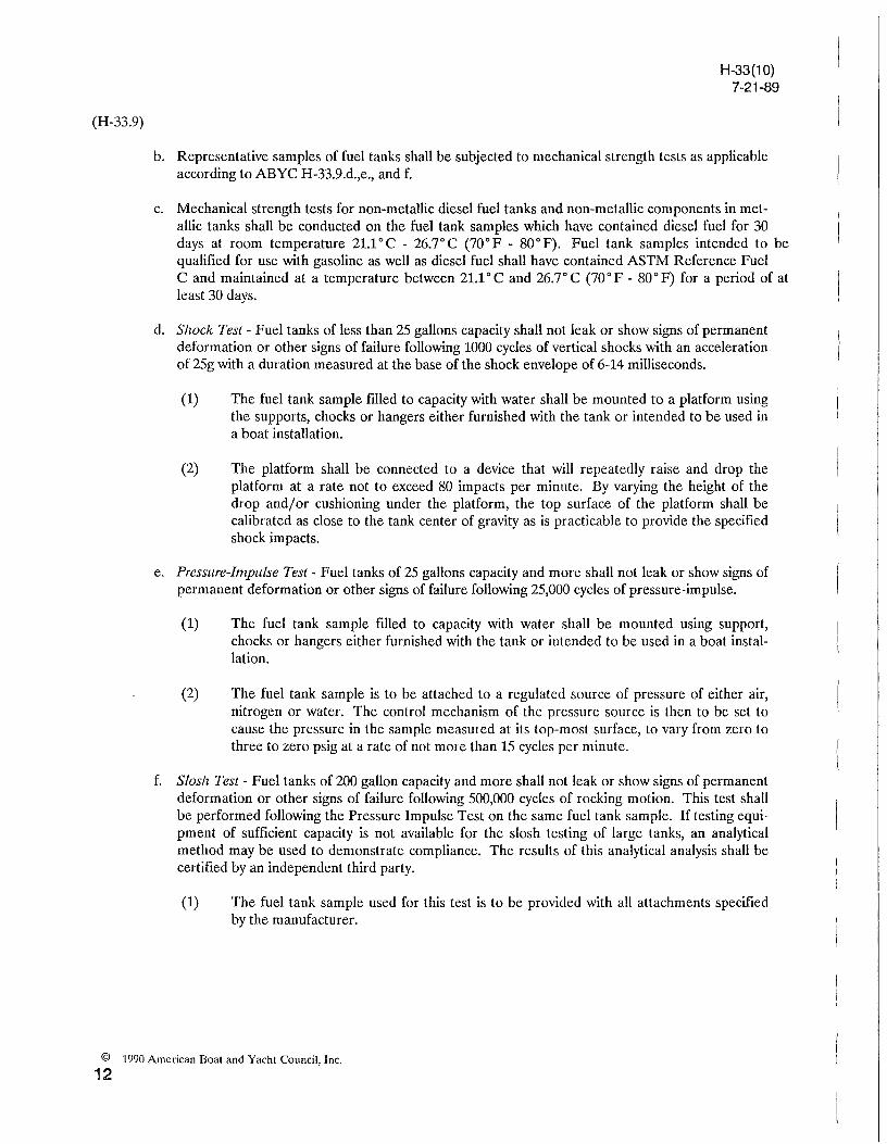
b. Representative samples of fuel tanks shall be subjected to mechanical strength tests as applicable according to ABYC H-33.9.d.,e., and f.
c. Mechanical strength tests for non-metallic diesel fuel tanks and non-metallic components in metallic tanks shall be conducted on the fuel tank samples which have contained diesel fuel for 30 days at room temperature 21.1°C - 26.7°C (70°F - 80°F). Fuel tank samples intended to be qualified for use with gasoline as well as diesel fuel shall have contained ASTM Reference Fuel C and maintained at a temperature between 21.1 ° C and 26.7° C (70° F - 80° F) for a period of at least 30 days.
d. Shock Test - Fuel tanks of less than 25 gallons capacity shall not leak or show signs of permanent deformation or other signs of failure following 1000 cycles of vertical shocks with an acceleration of 25g with a duration measured at the base of the shock envelope of 6-14 milliseconds.
(1) The fuel tank sample filled to capacity with water shall be mounted to a platform using the supports, chocks or hangers either furnished with the tank or intended to be used in a boat installation.
(2) The platform shall be connected to a device that will repeatedly raise and drop the platform at a rate not to exceed 80 impacts per minute. By varying the height of the drop and/or cushioning under the platform, the top surface of the platform shall be calibrated as close to the tank center of gravity as is practicable to provide the specified shock impacts.
e. Pressure-Impulse Test - Fuel tanks of 25 gallons capacity and more shall not leak or show signs of permanent deformation or other signs of failure following 25,000 cycles of pressure-impulse.
(1) The fuel tank sample filled to capacity with water shall be mounted using support, chocks or hangers either furnished with the tank or intended to be used in a boat installation.
(2) The fuel tank sample is to be attached to a regulated source of pressure of either air, nitrogen or water. The control mechanism of the pressure source is then to be set to cause the pressure in the sample measured at its top-most surface, to vary from zero to three to zero psig at a rate of not more than 15 cycles per minute.
f. Slosh Test - Fuel tanks of 200 gallon capacity and more shall not leak or show signs of permanent deformation or other signs of failure following 500,000 cycles of rocking motion. This test shall be performed following the Pressure Impulse Test on the same fuel tank sample. If testing equipment of sufficient capacity is not available for the slosh testing of large tanks, an analytical method may be used to demonstrate compliance. The results of this analytical analysis shall be certified by an independent third party.
(1) The fuel tank sample used for this test is to be provided with all attachments specified by the manufacturer.
© 1990 American Doat and Yacht Council, Inc.
12
(H-33.9.f.)
H-33(10) 7-21-89
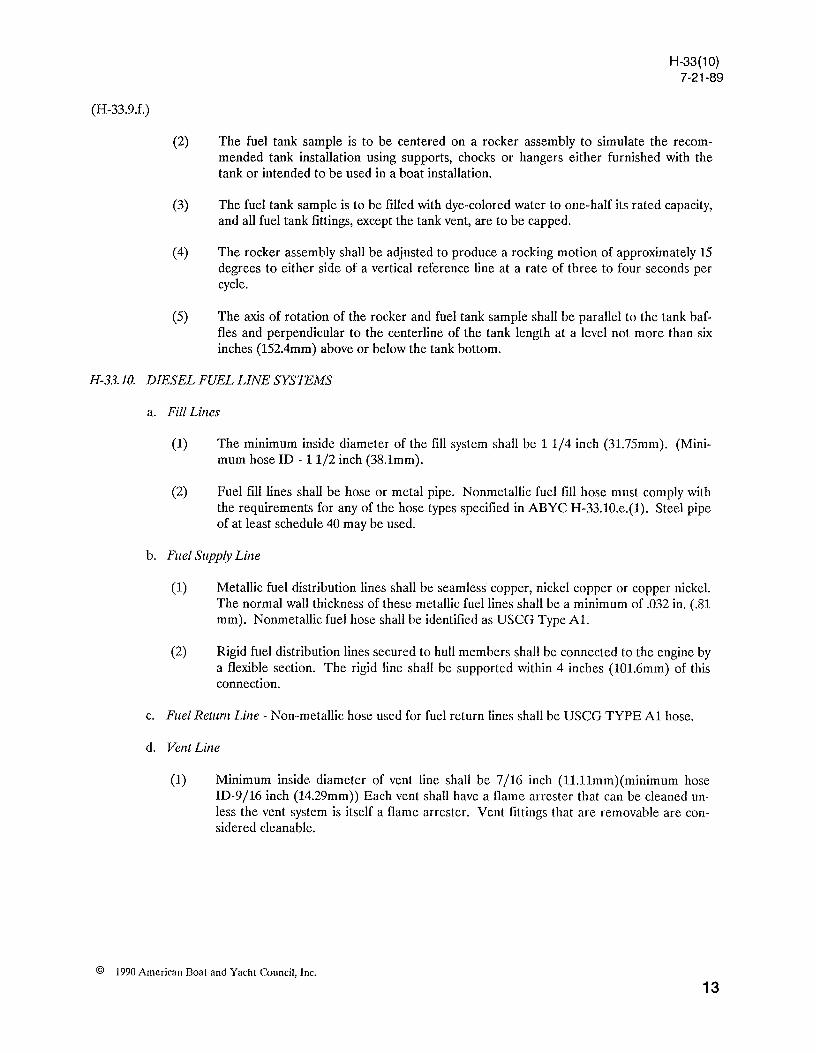
(2) The fuel tank sample is to be centered on a rocker assembly to simulate the recommended tank installation using supports, chocks or hangers either furnished with the tank or intended to be used in a boat installation.
(3) The fuel tank sample is to be filled with dye-colored water to one-half its rated capacity, and all fuel tank fittings, except the tank vent, are to be capped.
(4) The rocker assembly shall be adjusted to produce a rocking motion of approximately 15 degrees to either side of a vertical reference line at a rate of three to four seconds per cycle.
(5) The axis of rotation of the rocker and fuel tank sample shall be parallel to the tank baffles and perpendicular to the centerline of the tank length at a level not more than six inches (152.4mm) above or below the tank bottom.
H-33.10. DIESEL FUEL LINE SY.STEMS
a. Fill Lines
(1) The minimum inside diameter of the fill system shall be 1 1/4 inch (3I.75mm). (Minimum hose ID - 11/2 inch (38.1mm).
(2) Fuel fill lines shall be hose or metal pipe. Nonmetallic fuel fill hose must comply with the requirements for any of the hose types specified in ABYC H-33.10.e.(I). Steel pipe of at least schedule 40 may be used.
b. Fuel Supp~y Line
(1) Metallic fuel distribution lines shall be seamless copper, nickel copper or copper nickel. The normal wall thickness of these metallic fuel lines shall be a minimum of .032 in. (.81 mm). Nonmetallic fuel hose shall be identified as USCG Type AI.
(2) Rigid fuel distribution lines secured to hull members shall be connected to the engine by a flexible section. The rigid line shall be supported within 4 inches (lOI.6mm) of this connection.
c. Fuel Retzlm Line - Non-metallic hose used for fuel return lines shall be USCG TYPE Al hose.
d. Vent Line
(1) Minimum inside diameter of vent line shall be 7/16 inch (ll.llmm)(minimum hose ID-9/16 inch (14.29mm» Each vent shall have a flame arrester that can be cleaned unless the vent system is itself a flame arrester. Vent fittings that are removable are considered cleanable.
© 1990 American Boat and Yacht Council, Inc.
13
(H-33.10.d.)
H-33(10) 7-21-89
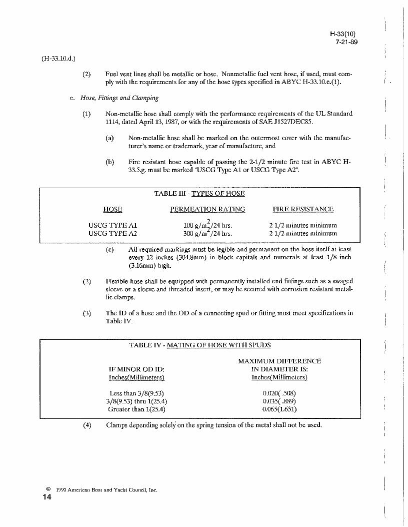
(2) Fuel vent lines shall be metallic or hose. Nonmetallic fuel vent hose, if used, must comply with the requirements for any of the hose types specified in ABYC H-33.10.e.(I).
e. Hose, Fittings and Clamping
(1) Non-metallic hose shall comply with the performance requirements of the UL Standard 1114, dated April 13, 1987, or with the requirements of SAE J1527DEC85.
(a) Non-metallic hose shall be marked on the outermost cover with the manufacturer's name or trademark, year of manufacture, and
(b) Fire resistant hose capable of passing the 2-1/2 minute fire test in ABYC H-33.5.g. must be marked "USCG Type Al or USCG Type A2".
TABLE III - TYPES OF HOSE
USCG TYPE Al USCG TYPEA2
PERMEATION RATING
2 100 g/mi24 hrs. 300 g/m /24 hrs.
FIRE RESISTANCE
2 1/2 minutes minimum 21/2 minutes minimum
( c) All required markings must be legible and permanent on the hose itself at least every 12 inches (304.8mm) in block capitals and numerals at least 1/8 inch (3.16mm) high.
(2) Flexible hose shall be equipped with permanently installed end fittings such as a swaged sleeve or a sleeve and threaded insert, or may be secured with corrosion resistant metallic clamps.
(3) The ID of a hose and the OD of a connecting spud or fitting must meet specifications in Table IV.
TABLE IV - MATING OF HOSE WITH SPUDS
IF MINOR OD ID: Inches(Millimeters)
Less than 3/8(9.53) 3/8(9.53) thru 1(25.4) Greater than 1(25.4)
MAXIMUM DIFFERENCE IN DIAMETER IS: Inches(Millimeters)
0.020( .508) 0.035( .889) 0.065(1.651)
(4) Clamps depending solely on the spring tension of the metal shall not be used.
© 1990 American Boat and Yacht Council, Inc.
14
(H-33.10.e.)
H-33(10) 7-21-89
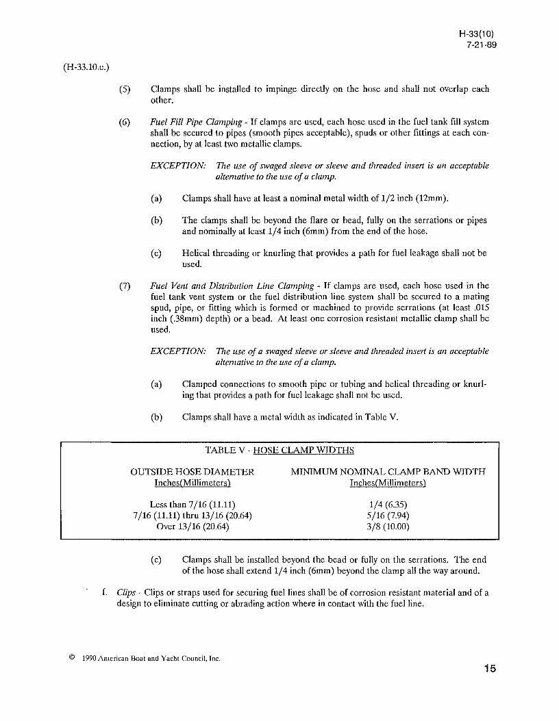
(5) Clamps shall be installed to impinge directly on the hose and shall not overlap each other.
(6) Fuel Fill Pipe Clamping - If clamps are used, each hose used in the fuel tank fill system shall be secured to pipes (smooth pipes acceptable), spuds or other fittings at each connection, by at least two metallic clamps.
EXCEPTION: The use of swaged sleeve or sleeve and threaded insert is an acceptable altemative to the use of a clamp.
(a) Clamps shall have at least a nominal metal width of 1/2 inch (12mm).
(b) The clamps shall be beyond the flare or bead, fully on the serrations or pipes and nominally at least 1/4 inch (6mm) from the end of the hose.
(c) Helical threading or knurling that provides a path for fuel leakage shall not be used.
(7) Fuel Vent and Distribution Line Clamping - If clamps are used, each hose used in the fuel tank vent system or the fuel distribution line system shall be secured to a mating spud, pipe, or fitting which is formed or machined to provide serrations (at least .015 inch (.38mm) depth) or a bead. At least one corrosion resistant metallic clamp shall be used.
EXCEPTION: The use of a swaged sleeve or sleeve and threaded insert is an acceptable altemative to the use of a clamp.
(a) Clamped connections to smooth pipe or tubing and helical threading or knurling that provides a path for fuel leakage shall not be used.
(b) Clamps shall have a metal width as indicated in Table V.
TABLE V " HOSE CLAMP WIDTHS
OUTSIDE HOSE DIAMETER Inches(Millimeters)
Less than 7/16 (11.11) 7/16 (11.11) thru 13/16 (20.64)
Over 13/16 (20.64)
MINIMUM NOMINAL CLAMP BAND WIDTH Inches(Millimeters)
1/4 (6.35) 5/16 (7.94) 3/8 (10.00)
(c) Clamps shall be installed beyond the bead or fully on the serrations. The end of the hose shall extend 1/4 inch (6mm) beyond the clamp all the way around.
f. Clips" Clips or straps used for securing fuel lines shall be of corrosion resistant material and of a design to eliminate cutting or abrading action where in contact with the fuel line.
© 1990 American Boat and Yacht Council, Inc.
15
H-33(10) 7-21-89
(H-33.10.)
g. Valves
(1) Manually operated valves shall be designed with positive stops in the open and closed positions or shall clearly and plainly indicate their opened and closed positions.
(2) Spring Valves - Tapered plug valves with an external spring shall not be used.
h. Fuel Filters and Water Separators - The diesel fuel system shall be equipped with at least one fuel filter. Consideration should be given to the use of water separators and if used they shall comply with the following requirements.
(1) Dirt removal ability (micron rating) shall be at least that as specified for the particular engine used.
(2) The unit shall incorporate means for independent mounting, designed to relieve strain from the connected fuel lines.
(3) The main filter closure shall comply with the following:
(a) The closure shall be designed so that its removal for cleaning purposes will minimize, as much as practicable, any spillage of fuel into the bilge.
(b) Gaskets and seals, if used, shall form a complete ring and shall not be split.
(4) Fuel filter bowls shall be:
(a) Highly resistant to shattering due to mechanical impact, and
(b) Resistant to failure due to thermal shock.
NOTE: Filters, Separators, and Strainers meeting the requirements of ANSI/ULII05 "Marine Use Filters and Separators" comply with these requirements.
1. Installation - Diesel Fuel System
(1) There must be no blow back of fuel through the fill fitting when filling at a rate of 9 gpm from 1/4 to 3/4 of the capacity on the tank label. For fuel tanks of 25 gallons capacity or less, the fill rate may be reduced to 6 gpm.
NOTE: A test to detennine compliance with this requirement may be perfonned on a representative sample.
© 1990 American Boat and Yacht Council, Inc.
16
(H-33.1O.i.)
(2) Fuel fill shall be located and oriented so that:
H-33(10) 7-21-89
(a) No fuel can enter the boat when it is in its static floating position and fuel overflows at a rate of 5 gpm for 5 seconds, and
(b) Separation between ventilation openings and fuel fills shall be at least 15 inches (381mm).
(3) Deck plates shall carry a permanent fuel-type identification, e.g. FUEL OIL or DIESEL, or the ISO symbol.
(4) Fill pipes shall run as directly as practicable, preferably in a straight line from the deck plate or other closeable plate to fuel tank top spud.
(5) Separation between ventilation openings and vent pipe terminations shall be at least 15 inches (381mm). The vent pipe shall have provision to minimize the intake of water without restricting the continuous release of vapor. Overflow at the rate of 2 gpm or less shall not enter the boat. No part of the vent system shall trap liquid.
(6) Vent pipe connections shall be from the highest point of the fuel tank as installed in the boat under conditions of normal operation and normal trim. In sailing auxiliaries, it may be necessary to have dual vents, each equal in size to the specification in ABYC H-33.10.d.
(7) Electrically operated fuel pump systems shall be connected to be energized only when the engine ignition switch is on and the engine is running. A momentary manual actuating switch to permit the electrical fuel pump to operate is acceptable for starting.
EXCEPTION: Electrical fuel pumps used to transfer fuel between tanks.
(8) Each fuel filter and strainer external to the fuel tank must be independently supported on the engine or hull structure.
(9) A shut-off valve is required at fuel tanks in installations in which fuel may siphon or in gravity feed systems.
H-33.11. DIESEL OUTBOARD POWERED BOATS
a. Outboard boats intended for use with only diesel as the propulsion fuel shall be so identified.
b. Fuel tanks and systems permanently installed within the hull shall be designed, constructed, and installed in accordance with this standard.
c. No pressurized tanks shall be built into or permanently attached to hulls.
© 1990 American Boat and Yacht Council, Inc.
17
(H-33.11.)
H·33(10) 7-21-89
d. A quick disconnect connection may be used between the motor and fuel distribution lines, but when it is disconnected, must automatically shut off fuel flow.
e. Fuel distribution lines shall be installed by the manufacturer III outboard powered boats equipped with permanent tanks. (See ABYC H-33.10.b.).
EXCEPTION: Fuel tanks with withdrawal fittings near the stem which, as installed, provide antisiphon protection.
f. Fuel distribution lines shall terminate at a fitting at the stern where provision is made for drainage or leakage. The stern fitting is not required if anti-siphon protection is provided by an anti-siphon or electrically operated valve.
* * * * *
© 1990 American Boat and Yacht Council, Inc.
18