Embed Size (px)
Citation preview

THE C-5A ACTIVE LIFT DISTRIBUTION CONTROL SYSTEM
William J . Hargrove Lockheed-Georgia Company
An Active L i f t Distribution Control System (ALWS) has been developed f o r the C-5A as a meana t o reduce wing fatigue damage due t o maneuver and gust load pources. The Lockheed-Georgia Company proposed a four phase program-8 the de- velopment and design of a prototype system, f l ight test evaluation, production pystem fabricat ion, and airplane fleet i n s t a l l a t i o n of t h i s Subsystem.
This paper describes the AIJ)CS development’and design tasks, ALDCS func- kional configuration, and resu l t ing challenges encountered while accomplishing .the first phase of the program. These Casks are establ ishing system require- ments and c r i t e r i a and synthesizing a system meohanization t o meet the desired load a l lev ia t ion , s t a b i l i t y margins, f l i g h t safety, and f ly ing qua l i t i e s per- formance. R e s u l t s of the BI;Dcs development and prototype system fl ight simula- t i on programs, and control law optimization including system s t a b i l i t y , handling qua l i t i e s and structural load analyses a r e presented, along with concluding re- marks r e l a t ive t o the system design integration.
An Active L i f t Distribution Control System (ALDCS) has been developed by Lockheed-Georgia Company under the direct ion of the USBF C-5 System Project Office t o reduce w i n g fa t igue damage due t o incremental maneuver and g u s t load sources .
The ALDCS is an automatic f l i g h t control subsystem which provides redis- t r ibu t ion of the wing spanwise l i f t through symmetrical deflection of the ailer- ons by inclusion of control inputs t o the ex is t ing lateral augmentation sub- system. The net a i l e ron control effect, as i l l u s t r a t e d i n figure 1, is t o sh i f t the wing spanwise center of pressure inboard, thus reducing the incremental wing root bending momenta. Control input signals from the ALDCS are a l s o provided t o the inboard elevator surfaces through the ex is t ing p i tch augnentation subsyetem f o r reduction of gust induced loads and t o compensate f o r the resulting deg- radation i n a i rplane handling qua l i t i e s .
Although the primary objective of the ALDCS is t o reduce wing loads, min- imizing the effects on the basic aircraft S t a b i l i t y and handling qualities and
32 5

t minimizing changes t o e x i s t i n g hardware while u t i l i z i n g e x i s t i n g con t ro l s u r - faces were a l s o basic design goals.
SYMBOLS AM) SWSCRIPTS
NZ 8
- 4
Ve
CADC
c .GO db, DB
ECP
E.Q.
*Z
K
KCAS
% PLDCS
PSF
PSD
Normal acce le ra t ion load f ac to r .
P i t c h rate.
Flap pos i t ion .
Bending moment . Aircraft
EQuivalent dynamic pressure.
m c e l e r a t i o n constant (32.2 ft/sec )
Mach number
2
EQuivalent Airspeed
Centrhl A i r Data Computer.
Center of grav i ty .
De c i b e 1
Elevator cable posit ion.
Handling q u a l i t i e s ,
Hertz.
One thcusand.
Knots c a l i b r a t e d airspeed.
Maximum hor izonta l f l i g h t Mach number.
Passive L i f t D i s t r ibu t ion Control System,
Pounds p e r square foot.
Power spectrum density.
Root mean square.
32 6

SYMBOLS BND SUBSCBIFTS (CONT'D)
VD Maximum dive f l i g h t a i r speed
SL Sea level.
VE Maximum hor izonta l f l i g h t airspeed.
vss Vehicle systems simulator.
L.S. Wing s t a t i o n .
BACKGROUND
I n 1969 the Lockheed-Georgia Company conducted a program t o e s t a b l i s h the f e a s i b i l i t y of reducing the maximum C-5 wing upbending loads during acce le ra t ed f l i g h t maneuvers. This e f f o r t cons is ted of development, f a b r i c a t i o n and f l i g h t test of a prototype subsystem r e f e r r e d t o a s t h e Maneuver LDCS (MLDCS). This subsystem success fu l ly reduced t h e inne r wing bending moments f o r pos i t i ve ac- ce l e ra t ions above 1.5g without degrading a i rp l ane handling q u a l i t i e s . A s i m - p l i f i e d vers ion of t h i s system known a s Pass ive L T S (PLDCS) t h a t involves manual a i l e r o n upr ig through the t r i m system w m sd lec ted f o r t he C-5 f l e e t in- corpor9tion.
I n 1972 a survey conducted by the C-5 S t r u c t u r a l Independent Review Team (IRT) of t h e poss ib le Lrlethods t o improve t h e C-5 wing fatigue l i f e characteris- t i c s included a recommendation t o consider an a c t i v e con t ro l system t o iroprove f a t igue l i fe . A decision was made j o i n t l y by t h e USAF C-5 Systems Pro jec t Office and Lockheed-Georgia Company t o develop and tes t such a subsystem which was t o be c a l l e d an Active L i f t D i s t r ibu t ion Control System. This subsystem was t o be incorporated i n a d d i t i c n t o the PLDCS. gram was i n i t i a t e d f o r t he development and test of a prototype subsystem with f l i g h t t e s t i n g t o be completed i n Ju ly of 1974. w i l l a f f e c t n decis ion t o produce t h e ALDCS f o r C-5 f l e e t r e t r o f i t .
I n May of 1973 the ALDCS pro-
The results of t h i s program
DENELOPMENT MElXODS
A flow c h a r t of t he tasks required i n the ALDCS development a r e shown i n figure 2. d i sc ip l ines t o in su re adequate a s s imi l a t ion of design requirements and data and proper maintenance of development results and t h e s t a t u s of t h e subsystem mech- anization. One of t h e paramount challenges was t h e i n t e g r a t i o n of the a f f e c t e d design d i s c i p l i n e s i n t o a t o t a l design team since the functioning of t h i s ac- tive subsystem had such interwovqn influences on loads, handling q u a l i t i e s , sta- b i l i t y , s t r u c t u r a l dynamics, and e x i s t i n g C-5 f l i g h t con t ro l systems. Fortu- na te ly , t he experience of t h e ear l ier LDCS program provided a n exce l l en t design example.
Each t a s k requi red d i r e c t involvement of I number of engineering
327

Requirements and Criteria
P r i o r t o s y n t h e s i z i n g t h e ALDCS, des ign requirements and c r i t e r i a were c a r e f u l l y e s t a b l i s h e d a s a des ign base i n t h e areas of s t r u c t u r a l l oads , f l i g h t c o n t r o l subsystems, s t a b i l i t y , and handl ing qualities. These requirements are:
S t r u c t u r a l Loads - O Continuous turbulence l c a d s a n a l y s i s shall r e s u l t i n RMS bending
moments a t t h e wing r o o t (wing s t a t i o n 120) no t exceeding 7% of t h e free a i r p l a n e values,
O The cont inuous turbulence RMS t o r s i o n a t t h e wing r o o t shall not exceed t h e free a i r c r a f t values by more than 5%.
O The ALDCS s h a l l no t i nc rease d i s c r e t e g u s t loads.
O The incrementa l r o o t bending momentb l o a d p e r g shall not exceed 7% of t h e f ree a i r c ra f t values du r ing s t e a d y maneuvers, w i t h i n t h e normal climb, cruise, and descent regime of t h e a i r c r a f t .
* The AIDCS shall produce no a i l e r o n i n p u t when t h e a i r c r a f t reaches t h e des ign p o s i t i v e maneuver l o a d f a c t o r of 2.5.
The system s h a l l no t be r equ i r ed t o ope ra t e i n t h e f l a p s down conf igu ra t ions .
O The AIICCS s h a l l ope ra t e i n t h e r equ i r ed s p e e d / a l t i t u d e f l i g h t envelope as def ined i n figure 3 f c r f l a p s up conf igura t ions .
F l i g h t C o n t r o l Bubsystems - O Yhe kLDC3 skiall be designed t o fJfail-safelt concepts.
The system shall be d dual channel ana log deeign.
O Active c p e r a t i o n G f a i l e r o n s and i n b o a d e l e v a t o r s through e x i s t i n g augmentation and primary c o n t r o l a c t u a t o r s are required.
O ALECY w i l l i n t e r f g c e w i t h e x i s t i n g C-5 s enso r s t o t h e e x t e n t p o s s i b l e and w i l l be compatible wi th e x i s t i n g C-5 au tomat ic f l i g h t con 'ir 01 subs ya tems e
No ALDCS mslfunctiGn w i l l a f fect n o m i l p i t c h and la teral a ugmenta t i o n subs ystem opera ti ons . The e x i s t i n g C-5 hydrau l i c s e rvoac tua to r s f o r t h e a i l e r o n and inboard e l e v a t c r s w i l l be used without modi f ica t ions .
328

O The ALDCS w i l l be required t o operate on a f f f u l l - t i m e basisff within t h e des i red f l i g h t envelope and design c r i t e r i a boundaries.
S t a b i l i t y - The incorporation of t h e ALDCS shall not:
O Induce adverse s t ruc tura l mode coupling.
O Change s i g n i f i c a n t l y t h e e x i s t i n g maneuvering f l i g h t handling q u a l i t i e s .
O Induce s i g n i f i c a n t degradation of e x i s t i n g f l u t t e r margins,
O Induce adverse coupling with e x i s t i n g f l i g h t con t ro l systems.
O Induce l i m i t cyc le tendencies.
The following A L N S minimum s t a b i l i t y margin and a t t e n t u i t i o n goals f o r each primary con t ro l surface feedback loop were es t ab l i shed t o meet t h e above system s t a b i l i t y requirements. These. goa ls were considered t o be real is t ic and a t t c i n a b l e throughout t he ALDCS f l i g h t envelope.
O 0 Ground Test - 6 db ga in margin and 45 degree phase margin.
O 0 F l i g h t mcdes through con t ro l mode natural frequencies - 6 db ga in margin and 45 degree phase margin.
O 0 F l i g h t modes above con t ro l mode n a t u r a l frequencies - 6 db ga in margin and i n f i n i t e phase margin. system a t t enua t ion goal of 60 db/decade e s t ab l i shed f o r t hese modes.
There was a l s o a
Handling Qua l i t i e s - O There shall be no s i g n i f i c a n t change i n t he e x i s t i n g C-5 handling
q u a l i t i e s . O The ALDCS s h a l l be disengaged p r i o r t o t h e a i rcraf t s t a l l event.
O C r i t e r i a f o r t h e C-5 handling q u a l i t i e s w i l l be those characteristics e s t ab l i shed during previous f l i g h t test programs which concluded t h e C-5A f l y i n g q u a l i t i e s t o be acceptable i n a l l cases.
O Evaluaticn p i l o t comments w i l l be u t i l i z e d t o obta in s a t i s f a c t o r y results.
Design Data Acquisit ion
The t a s k of acqui r ing necessary design data was s impl i f i ed by the exis- tence of a i r p l a n e math model data, f l i g h t con t ro l subsystem mechanizations,
329

and f l i g h t test response c o r r e l a t i o n data from the o r i g i n a l C-5 design programs. The major void i n design information existed i n the characteristics of t h e a i l - eron and e l eva to r hydraulic servoactuaters. ac tua to r s being designed and t e s t e d pr imar i ly f o r handling q u a l i t i e s evalua- t ions and automatic s t a b i l i z a t i o n of a i r c r a f t low frequency s h o r t period and dutch r o l l modes, whereas t h e A L E S would encompass t h e sensing and active con t ro l of higher frequency a e r o e l a s t i c mode dynamics, p o t e n t i a l l y up t o a f a c t o r of I 5 above the s h o r t period frequency.
This void existed due t o the C-5
These mis s ing a c t u a t o r characteristics not only included frequency re- sponse bu t h y s t e r e s i s , surface rates and to le rance bands i n unloaded and load- ed conditions. They were des i red f o r a c t u a t o r s of various ages up t o a n ex- pected f u l l l i fe . These data were obtained by tests on t h e C-5 Vehicle Systems bimulator of new and worn (over one l i f e span) servoac tua tors , by tests per- formed by Bertea Corporation ( the servoactuator manufacturer), and by frequen- cy response f l i g h t tests on the C-5 aircraft .
A d e f i n i t e "design r i sk" was assoc ia t ed with the attempt t o u t i l i z e e x i s t i n g C-5 servoactuatore witt;out bandwidth o r a u t h o r i t y l i m i t modifications.
Computer Programs
Various computer programs were prepared and co r re l a t ed with f l i g h t tes t data t o provide a n s l y t i c a l techniques f o r development of t he A L E S mechaniza- t i on , These programs using hybrid and d i g i t a l computation were:
O S t a b i l i t y - Eigenvalues and Frequency Response
O Dynamic Time His tory - Loads and Handling Qualities
O Accelerated S t a b i l i t y - St i ck Force pe r 'gf
O PSD Loads
The following a i r p l a n e and con t ro l system a n a l y t i c a l models were used f o r t he above programs.
O Three degrees-of-freedom quas i -e las t ic longi tudina l a x i s dynamic models.
S ix degrees-of-freedoE quas i - e l a s t i c long i tud ina l and l a t e ra l -d i r ec t iona l axes dynamic models.
O Eighteen mode a e r o e l a s t i c symmetric axis dynamic models, with first 15 f l e x i b l e mcdes and Wagner and Kussner functions and gust pene t ra t ion e f f e c t s ,
O Two degrees-of-freedom quas i -e las t ic steady-state maneuver model.
O Eight mode a e r o e l a s t i c symmetric a x i s dynamic model with s i x most s i g n i f i c a n t f l e x i b l e modes.
330
L

O Linear and non-linear f l i g h t con t ro l system servoac tua tor models.
A n a l y s i s and Synthesis Tasks
The a n a l y s i s and synthes is t a sks involved t h e development of an ALDCS mechanization t o meet t h e load a l l e v i a t i o n requirements and the determination of i ts effects on s t a b i l i t y , handling q u a l i t i e s and e x i s t i n g f l i g h t con t ro l subsystem performance. Feedback con t ro l laws were synthesized t o a t t a i n these requirements while minimiraing system coupling effects with undesirable s t ruct- u r a l modes and r i g i d body dynamics.
Development of a r e a l i s t i c mechanization that could p o t e n t i a l l y be u t i l - i z ed as a guide f o r production design t h e system's t o t a l f l i g h t envelope func t iona l c h a r a c t e r i s t i c s , sensor to le rance and response spec i f i ca t ions , and p r o t o t n e parameter a d j u s t c a p a b i l i t i e s . Also involved were the analyses t o determine e f f e c t s of subsystem failures, component to le rance build-up, and servoac tua tor response c h a r a c t e r i s t i c s . Other major a n a l y t i c a l s t u d i e s were accomplished t o determine the impact of t he A L E 8 on handling q u a l i t i e s i n t h e following a reas :
required indepth s t u d i e s t o e s t a b l i s h
O Dynamic S t a b i l i t y
O Maneuverability ( A t t i t u d e Control)
O Accelerated S t a b i l i t y (St-ick Force pe r ' g f )
O Rol l Control Performance
O Development of a n ALDCS Handling Qual i t ies Command Nodel
The i n t e r a c t i o n coupling e f f e c t s of t he f l e x i b l e bending and r i g i d body response with the f l i g h t con t ro l system was thoroughly analyzed. This insured proper c o n t r o l law compensation f o r those f l i g h t conditions during which s t ruct- u r a l modes and handling q u a l i t i e s tend t o degrade each other.
F l i g h t Simulaticn Tasks
Tasks accomplished on t h e C-5 Developmental Handling Qua l i t i e s Cockpit Simulator provided p i l o t eva lua t iens of t h e AI;DCS e f f e c t on the C-5 handling characteristics. s i s t e d of t he following:
The i n f l i g h t t a sks performed by t h e eva lua t ing p i l o t con-
O Symmetric 'g' pull-ups
O S t a b i l i z e d batik tu rns and ro l l -outs
Landing approach and f l a r e
331

O Constant 'gf r o l l i n g pull-out maneuvers
O Take-of f r o t a t i o n s
O At t i tude t racking maneuvers during turbulence
O A i r t ra f f ic con t ro l maneuvering (speed, a l t i t u d e and heading changes)
The C-5 Developmental Handling Qual i t ies Cockpit Simula t o r is real-time s ix degrees-of-freedom s i m l a t i o n with an a l l digital computatjon and a termi- na l m e a t e r r a i n medel visual system.
Vehicle Systerc Simulator (VSS) Tasks
Simulation a f forded the c a p a b i l i t y t o v e r i f y the prototype design and system s a f e t y a spec t s i n func t iona l operation checkout and f l i g h t con t ro l sub- system haraware in t eg ra t ion , This technique a l s o provided f ina l p i l o t evalua- t i ons u t i l i z i n g t h e prototype subsystem. ueed on the C-5 Developmental Handling Qualities Cockpit Simulation discussed previous 1 y .
P i l o t t a sks were similar t o those
The VSS incorporates a c t u a l C-5 mechanical and hydraulic f l i g h t con t ro l systems , moving sur faces and i n t e r f a c i n g automatic f l i g h t con t ro l subsystems.
The accomplishment of t h e ana lys i s , syn thes i s , simulation and design tasks t o meet a restrictive schedule was paramount. F l i g h t test evaluations of t he prototype ALDCS were t o begin wi th in eleven months from con t rac tua l go-ahead, Figure 4 i l lustrates t h e c r i t i c a l i t y of the design program schedule. go-ahead occurrinq on 7 M y 1973, t h e subsystem design met the 90 percent func- t i o n a l r e l e a s e date of 21 Septeaber 1973. The f inal mechanization was re leased on the scheduled aate of 7 November 1973 and t h e first prototype subsystem was made ava i l ab le f o r f l i g h t simulation eva lua t ion on 7 January 1974. system evaluations began on 15 Wirch 1974, approximately t e n months a f t e r go- ahead.
With
I n f l i g h t
SYSTEN M E C M I Z A T I O N
The ALDCS has been mechanized t o meet t h e demanding requirements placed on it and t o i n t e r f a c e with e x i s t i n g C-5 sensors, augmentation and servo- ac tua t ion s ubs ys tems
332

Figure 5 provides a s impl i f i ed i n t e r f a c e diagram ind ica t ing the integrti- t i o n of t h e AQCS computer wi th the e x i s t i n g C-5 f l i g h t con t ro l subsystems. The dual channel redundancy design ALDCS computer provides signals t o both the l a t e r a l augmentation series servo t o con t ro l t he a i l e r o n ac tua to r s sy~imetrical- l y and t h e p i t c h augmentation series servo t o a c t u a t e the inboard e l eva to r con- t r o l surfaces, Aileron ac tua to r s a l s o rece ive commands from t h e pi . iots, auto- p i l o t , and passive LDCS. The p i l o t s and a u t o p i l o t command inboard a s w e l l as outboard e l eva to r s , sensors and i n t e r f a c i n g computers and a f f ec t ed con t ro l sur faces , mounted accelerometers a r e t h e only add i t iona l C-5 sensors required f o r ALDCS in tegra t ion .
Figure 6 shows t h e C-5 a i r p l a n e loca t ions of t he ALDCS The wing
The ALDCS mechanization c o n s i s t s of a n a r r a y of sensors , ga ins , and f i l - Figure 7 is a block diagram of the AIJ3cS s impl i f i ed mechanization t o be ters.
used a s a roadmap during t h e insu ing discussion of t he ind iv idua l components and system development changes. cussed separa te ly .
The a i l e r o n and e l e v a t o r channels w i l l be dis-
Aileron Channel .
The a i l e r o n con t ro l channel commands the r i g h t and l e f t a i l e r o n s symmet- r i c a l l y t o accomplish the maneuver load r e l i e f function, The feedback sensors u t i l i z e d f o r t he a i l e r o n channel a r e provided by two v e r t i c a l accelerometer loca t ions per wing, one loca ted on t h e forward main beam (W.S. .i186) and t h e o the r on t h e r e a r beam (W.S. 1152) bo th a t a n ou te r wing location. frcm these accelerometers a r e averaged and compensated by smoothing f i l t e r s t h a t a t t enua te sensor noise and a i d i n the e l imina t ion of higher frequency wing v ib ra t ion modes beyond t h e ALDCS con t ro l bandwidth.
The signals
The S t a b i l i t y and Load Control Gain and F i l t e r i n g por t ion of t h e a i l e r o n channel provides the necessary compensation t o adequately phme the feedback accelerometer signals f o r con t ro l of t h e inne r wing bending moments and t o a t - t a i n the design goa l s t a b i l i t y margins,
A p i l o t ' s feedforward comnand, acquired from the e x i s t i n g C-5 e l eva to r cable pos i t i on (ECP) transducer, is summed with t h e compensated acce le ra t ion con t ro l s i g n a l t o provide abrupt maneuver load cont ro l . nal is f i l t e r e d f o r proper abrupt load a l l e v i a t i o n a i l e r o n command phase,
The feedforward sig-
These con t ro l signals a r e then gain scheduled by a i r c r a f t dynamic pres- sure from the Cent ra l A i r Data Computer (CADC) t o provide proper s t a b i l i t y and load relief schedules and t o minimize handling q u a l i t i e s degradations through- ou t the a i rcmft speed envelope. Cut-off f i l t e r s are provided t o preclude ad- verse coupling with higher frequency uncontrolled modes, command s i g n a l is con t ro l l ed by boundary cont ro l l og ic which contains the c i r - c u i t r y t o disengage t h e signal when exceeding f l i g h t boundaries where the ALDCS is not required. These opera t iona l boundary cosdi t ions a r e when the f l a p s a r e lowered, t h e S t a l l i m i t e r subsystem is ac t iva t ed , t he a i r p l a n e exceeds maximum
The ALDCS a i l e r o n
333

hor i zon ta l airspeed/Mach (350 KCBS /I1 = 0.825), and! when the a i r p l a n e load f a c t o r exceeds 1.9 g*s. aircraf t subsystems d t h the exception of load f ac to r . This s i g n a l is derived from ALDCS wing and fuselage accelerometers t o c l o s e l y represent aircraft C.G. acce lera t ion . t h e ALDCS o p e r a t i and in t e r f aced with t h e la te ra l SAS a i l e r o n series servoactuators.
These log ic con t ro l s i g n a l s a r e obtained from e x i s t i n g
The system i s au tomat ica l ly re-engaged as t h e a i rc raf t re-enters The a i l e r o n command s i g n a l is then l imi t ed 1 envelope.
Elevator Channel
The e l eva to r channel ccnta ins th ree sensors , two active feedback param- eters and one feedforward command. p i t c h SAS r a t e gyro , is u t i l i z e d t o augment the a i r p l a n e s h o r t period damping and thereby a l l e v i a t e t h e e x c i t a t i o n of s h o r t period induced gust loads and t o r e s t o r e t h e handling q u a l i t i e s degraded by the a i l e r o n p i t ch ing moment e f f e c t s .
Airplane p i t c h r a t e , a s provided by the
An e x i s t i n g C-5 a u t o p i l o t subsystem v e r t i c a l accelerometer mounted i n t h e forward fuselage provides add i t iona l gust load con t ro l and compensates the a i r - plane p i t c h response c h a r a c t e r i s t i c s .
A feedforward s i g n a l , p i l o t ' s eleviitor input ccmmnd, is requi red t o re- s tore t h e a i rp l ane maneuverability and acce le ra t ed s t a b i l i t y ( s t i c k fo rce pe r 'g') c h a r a c t e r i s t i c s t'hat a r e s i g n i f i c a n t l y degraded by the load con t ro l sig- nhls. 'This s i q n e i is scheduled a s a func t ion of a i r p l a n e dynaniic pressure tlnd oompensated by ti comand model f i l t e r t o provide the proper system handling q u a l i t i e s throughout t he opera t iona l envelope.
These three s i g n a l s , p i t c h rate, normal acce le ra t ion and p i l o t e l eva to r command input a r e summed and aga in scheduled with dynamic pressure and passed through system cut-off f i l t e r s f o r s t a b i l i t y and g u s t load con t ro l phasing.
The e l eva to r signal is provided t o a boundary con t ro l l og ic network that disengages the signal under the 9itL.e conditions as the a i l e r o n channel.
This c i r cu i t includes a fade-out f i l t e r t o minimize acce le ra t ion t r a n s i e n t s r e s u l t i n g from abrupt sur face disengagement. The command signal is then l i m i t - ed and in t e r f aced with t h e p i t c h augmentation subsystem.
Sys tem Changes
The func t iona l development of t h e AUCS provided t h e u s u a l subsystem c h n g e s which caused agonizing per turba t ions i n t h e design of t he prototype subsystem hardware. These modifications of t h e mechanization f a l l i n t o the fo l lov ing major areas:
O Wing accelerometer l oca t ion
O Operational f l i g h t envelope
334

O Subsystem s t a b i l i t y - f i l t e r compensation
Wing Accelerometer Location - Trade s t u d i e s were accomplished t o determine t h e number and loca t ions of
t h e wing mounted accelerometers, i n s t a l l a t i o n are e s s e n t i a l l y l imi t ed t o the f r o n t and rear beams due t o f u e l tank locations. Original s t u d i e s of t he wing accelerometer l oca t ion ind ica ted the need f o r two sensors pe r wing, one on the mid-wing a f t main beam and one i n t h e outer wing t o be mounted on t h e f r o n t main beam. v ide "high gain" feedback con t ro l of t h e f i r s t and second wing f l e x i b l e bending modes. Additional s t u d i e s proved t h e "high gain" system design t o be impracti- ca l and t h a t t h e second wing mode d id not con t r ibu te s i g n i f i c a n t l y t o g u s t loads, thus the mid-wing sensor loca t ions were eliminated, This removal and r e loca t ion of t h e ou te r wing f r o n t beam accelerometer t o the r e a r beam, caused a favorable inf luence on subsystem s t a b i l i t y and allowed the maneuver and gust load con t ro l functions t o be simply combined with reduced gains i n t h e a i l e r o n channel .
The C-5 w i n g l oca t ions acceptable t o sensor
These sensors were t o pro-
La ter a second accelerometer was placed i n . i t s present l oca t ion on t h e f r o n t beam t o mjninize a 48 rad ian per second ou te r wing coupling mode tha t , i n tu rn , increased the s t a b i l i t y margins and eliminated an o r i g i n a l need f o r com- p lex notch fi l tering. Figure 8 ind ica t e s t he effect of single and blended mul- t i p l e accelerometer loca t ions on t h e ALDCS a i l e r o n closed loop frequency re- sponse. The r e a r bean sensor p e r n i t s a n amplitude ga in peak of 7 db a t 48 rad- i ans per second, blended with t h e r e a r accelerometer t o simulate t h e c r i t i c a l 48 radians pe r sec- ond node loca t ion , reduces t h i s peak t o approximately one db. An ex te rna l wing accelerometer i n s t a l l a t i o n was considered; however, the a d d i t i o n a l c o s t and assoc ia ted design r i s k s eliminated t h i s desiga.
The add i t ion of t he f r o n t beam accelerometer adequately
Operational F l i g h t Envelope - To insu re proper func t ioning of t he ALES throughout t h e required f l i g h t
envelope, ga in scheduling and subsystem disengagement are necessary. The orig- i n a l subsystem mechanization requi red complex nonlinear scheduling i n t e r f a c e s with the c e n t r a l a i r data computer. A s t h e development progressed these sched- ules were s impl i f i ed t o l i n e a r functions. Also a n o r i g i n a l ALDCS requirement f o r f l a p s down operation was dele ted , thereby e l i m i m t i n g the need f o r f l a p ga in schedules and automatic landing in t e r f aces . by a f l a p s down boundary log ic c o n t r o l disengagement signal. Another change necess i ta ted by f l i g h t envelope requirements was t he development of a f a d e r t o smoothly disengage t h e subsystem when t h e a i rp l ane exceeds the boundary condi- t i o n of noma1 acce le ra t ion , s t a l l approach, and speed/Mach. Acceptable hand- l i n g q u a l i t i e s were a t t a i n e d a t these boundary conditions with a simple t m c k and fade-out c i r c u i t i n the e l eva to r channel.
These functions were replaced
335
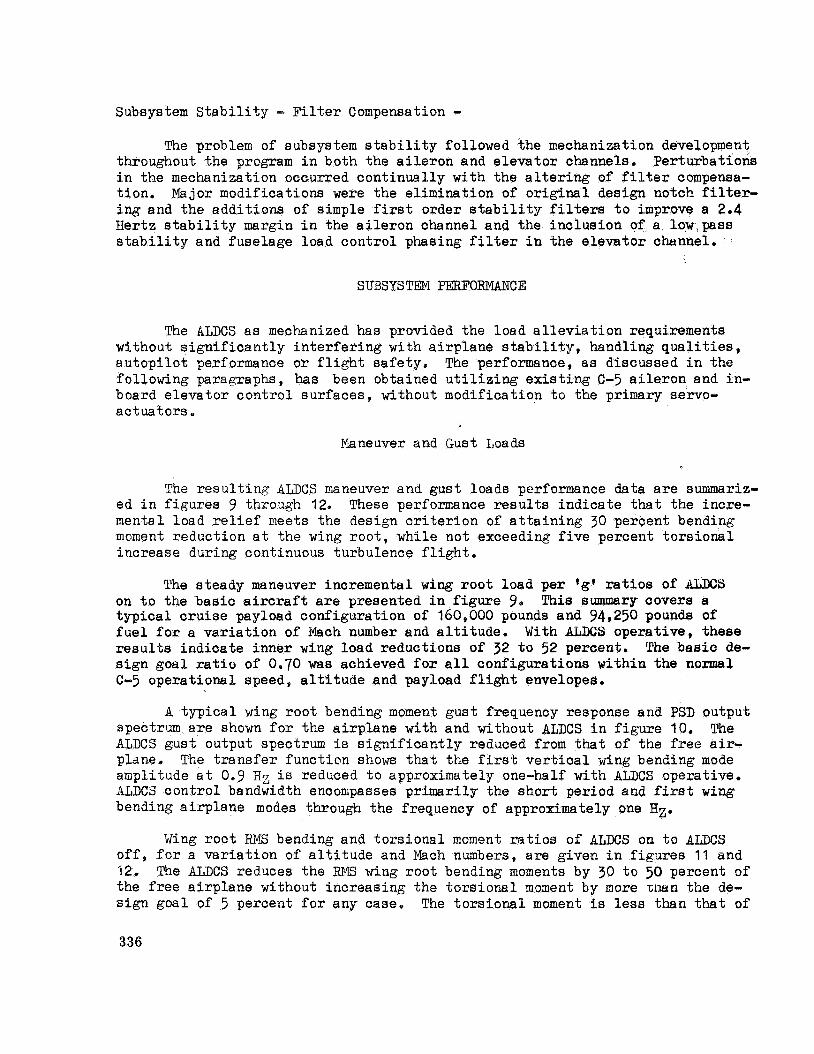
Subsystem S t a b i l i t y - F i l t e r Compensation - The problem of subsystem s t a b i l i t y followed the mechanization development
throughout t he program i n both the a i l e r o n and e l eva to r channels. i n t he mechanization occurred cont inua l ly with the a l t e r i n g of f i l t e r compensa- t ion . ing and t h e add i t ions of simple f i r s t order s t a b i l i t y f i l t e r s t o improve a 2.4 Hertz s t a b i l i t y margin i n the a i l e r o n channel and the inc lus ion of a low,pass s t a b i l i t y and fuse lage load con t ro l phasing f i l t e r i n the e l eva to r channel.
Per turba t ions
Major modifications were t h e e l imina t ion of o r i g i n a l design notch f i l t e r -
S'UBSYSTm PERFORMANCE
The kLDCS a s mechanized has provided the load a l l e v i a t i o n requirements without s i g n i f i c a n t l y i n t e r f e r i n g with a i r p l a n e s t a b i l i t y , handling q u a l i t i e s , a u t o p i l o t performance o r f l i g h t s a fe ty . The performance, a s discussed i n the follo-xing paragraphs, has been obtained u t i l i z i n g e x i s t i n g C-5 a i l e r o n and in- board e l eva to r con t ro l sur faces , without modification t o the primary servo- ac tua tors .
Ijlaneuver and G u s t Loads
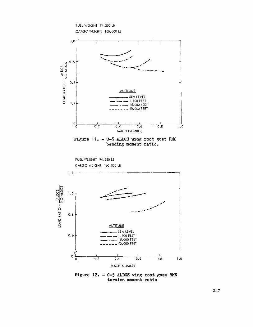
The r e s u l t i n g ALDCS maneuver and gust loads performance data a r e summariz- ed i n f igu res 9 through 12. These perfomance results ind ica t e that the incre- mental load r e l i e f meets t he design c r i t e r i o n of a t t a i n i n g 30 percent bending moment reduction a t t he wing r o o t , while not exceeding five percent t o r s i o n a l increase during continuous turbulence f l i g h t .
The s teady maneuver incremental wing r o o t load pe r ( g c r a t i o s of ALDCS on t o t h e bas i c a i rc raf t are presented i n figure 9, t y p i c a l cruise payload conf igura t ion of 160,000 pounds and 94,250 pounds of fuel f o r a v a r i a t i o n of Mach number and a l t i t u d e . resul ts ind ica t e inne r wing load reductions of 32 t o 52 percent. s i g n goa l r a t i o of 0.70 was achieved for a l l conf igura t ions within the normal C-5 operationcll speed, a l t i t u d e and payload f l i g h t envelopes.
This summary covers a
With ALDCS opera t ive , t hese The bas i c de-
A t y p i c a l wing roo t bending moment g u s t frequency response and PSD output spectrum a r e shown f o r t he a i r p l a n e with and without AZ;DCS i n figure 10. The ALDCS gust output spectrum is s i g n i f i c a n t l y reduced from that of the free a i r - plane, The t r a n s f e r func t ion shows that the first v e r t i c a l wing bending mode amplitude a t Oe9 Hx is reduced t o approximately one-half with AmCS operative. ALDCS c o n t r o l bandwidth encompasses p r imar i ly the s h o r t period and f i rs t w i n g bending a i r p l a n e modes through t h e frequency of approximately one Hz.
o f f , f o r a v a r i a t i o n of a l t i t u d e and Mach nmbers , Eire giver- i n f igu res 11 and 32. The ALES reduces t h e WIS wing roo t bending moments by 30 t o 50 percent of t he free a i r p l a n e without increas ing t h e t o r s i o n a l moment by more m a n the de- s i g n goa l of 5 percent f o r any case. The t o r s i o n a l moment i s less than that of
Wing root RT4.S bending and to r s iona l moment r a t i o s o f ALDCS on t o ALDCS
336

t h e bas i c a i r p l a n e f o r t h e major i ty of f l i g h t cases investigated.
Loads cri teria f o r discrete g u s t were only s p e c i f i e d t o the ex ten t that the ALDCS shall not increase the basic a i rp l ane discrete gust loads. Seven f l i g h t cases , similar t o those presented i n figure 9, were analyzed f o r t h e
"1-cosine" d i s c r e t e g u s t model. The wing root bending inoclent peaks, with ALDCS on, were reduced t o values ranging from 78 t o 52 percent sf t h e free a i r - plane f o r t he c r i t i c a l gust frequency wavelengths.
Although no cri teria were es t ab l i shed f o r abrupt maneuver load con t ro l , analyses were conducted t o eva lua te the e f f e c t of ALDCS on abrupt maneuver load con t ro l characteristics. These analyses, conducted f o r seven s e l e c t e d f l i g h t conditions, revealed that t h e load reduction was from one t o seventeen percent depen6ing upon t h e p a r t i c u l a r f l i g h t case response c h a r a c t e r i s t i c s . I n a n ef- f o r t t o improve t h i s performance, a feedfomard p i t c h con t ro l command signal was provided t o t h e a i l e r o n channel. feedforward s i g n a l f o r a selected number of c r u i s e f l i g h t conditions ind ica t ed t h a t t he wing roo t bending moments could be reduced by 30 percent of t h e basic a i rp lane . This feedforward signal mechanization was then incorporated i n the A L E S prototype system f o r f l i g h t test evaluation.
Results of ana lys i s w i t h the a i l e r o n
Fuselage loads performance was monitored during the continuous turbulence ana lys i s t o eva lua te the effects of ALDCS. Results ind ica ted t h a t t h e a f t fuselage bending moments were being increased up t o 15% over the f r e e a i rp lane . 4 low-pass f i l t e r was added t o t h e e l eva to r channel that increased s t a b i l i t y margins and decreased the a f t body fuselage bending moments below those of t he bas i c a i q l a n e f o r a l l cases.
S t a b i l i t y
The concern t h a t t he ALNS possess adequate s t a b i l i k y ga in and phase margins caused considerable design optimization a t t en t ion . ment was accomplished a s ind ica ted i n figures 13 and 14. These ga in and phase margins represent a series of reserve f u e l loading cases that inherent ly pos- sess the minimum a i l e r o n loop s t a b i l i t y . The e l eva to r loop s t a b i l i t y is mini- mum with a high fuselage cargo loading, bu t i n no cases were t h e phase margins less than 64 degrees o r t h e ga in margins less than 10 db.
This require-
The ga in margins f o r both a i l e r o n and inboard e l eva to r channels a r e w e l l above t h e minimum requirement of 6 db f o r a l l cases.
The only f l i g h t case found t o have t h e minimum phase margin of 45 degrees was that of a high a l t i t u d e , reserve f u e l and maximum ALDCS opera t iona l Mach number of 0,825. A s f u e l weight is added t o t h i s configuration, t h e a i l e r o n ga in and phase margins a r e increased. A f u e l capac i ty of approximately 30
337

percent f o r t h i s case has a ga in margin of 16.5 db and a phase margin of 62 de- grees .
Ninimum a i l e r o n ga in and phase margins f o r a l l configurations occur a t frequencies between 33 t o 53 rad ians pe r second and between 6 and 17 rad ians p e r second, respectively. The minimum e leva to r ga in margins f o r a l l configurations occur a t frequencies between 6 and 8.6 rad ians p e r second with the phase margin frequencies ranging from 0.6 t o 3.41 rad ians pe r second.
Handling Qualities
1! b a s i c ALDCS design goal was that the re would be no s i g n i f i c a n t degrada- t i o n of t h e e x i s t i n g C-5 handling q u a l i t i e s . the-loop f l i g h t simulation evaluations were accomplished t o in su re that the ALDCS was compatible with the C-5 f l y i n g characteristics.
Extensive ana lys i s and pilot-in-
The handling q u a l i t y a reas of most concern that could be a l t e r e d o r sig- n i f i c a n t l y degraded by t h e SLUCS were:
O Maneuver response
O Accelerated s t a b i l i t y - s t i c k fo rce pe r ?g'
O Short period s t a b i l i t y
O Phugoid s t a b i l i t y
O Roll performance
Development of a n ALDCS e leva to r channel p i l o t command model f i l t e r was
ALDCS s h o r t period and phugoid s t a b i l i t y effects were compensated by e s s e n t i a l t o r e t a i n t h e C-5 maneuver response and s t i c k force p e r ?g* character- i s t i c s . appropriate system ga in and f i l t e r parameter optimization. The r o l l performance e f f e c t was g r e a t l y reduced by using t h e minimum a i l e r o n channel ga in schedule re- quired f o r maneuver load control.
The time h i s t o r i e s shown i n figure 15 present t he effects of ALDCS on a i r - plane normal C.G. a cce l e ra t ion and p i t c h rate responses f o r a t y p i c a l pull-up maneuver. The inpu t fo rc ing func t ion f o r t h i s maneuver is a constant con t ro l force rate and hold a f t e r 3 seconds. This figure shows that the time t o obta in steady-state maneuver values a r e p r a c t i c a l l y t h e same with ALDCS off o r on. only d i f fe rence wi th ALDCS on is that of a s l i g h t undershoot i n peak p i t c h rate and a s l i g h t rise time improvement t o acqui re the s teady s t a t e response. Simu- l a t o r p i l o t ev8luations of t hese type maneuvers ind ica ted no degradation i n a i r - plane handling q u a l i t y performance.
The
The longi tudina l axis accelerated maneuvering s t a b i l i t y , a s shown i n f ig- The ALDCS s t i c k fo rce pe r ure 16, was not s i g n i f i c a n t l y impaired by t h e ALDCS.
lg' values a r e well within t h e demonstrated boundaries of previously ex t r ac t ed
338

f l i g h t test da t a wi thout ALNS. The s t eady- s t a t e e l e v a t o r command model g a i n was optimized t o provide i d e n t i c a l s t i c k f o r c e p e r 'gf characteristics f o r mid C.G. f l i g h t conf igu ra t ions wi th ALDCS on o r o f f . P i t c h column f o r c e r equ i r ed t o hold a g iven a c c e l e r a t i o n f o r forward and a f t C.G. wi th ALDCS on are s l i g h t - l y decreased and inc reased , r e s p e c t i v e l y from t h e b a s i c a i r p l a n e . The s i m u l h t - o r p i l o t s were unable t c d i s t i n g L i s h t h e s e ALDCS characteristics from those of t h e b a s i c a i r p l a n e .
No s h o r t pe r iod and phugoid s t a b i l i t y damping degrada t ion 'was no t i ced dur i ng t h e devefopzent f l i g h t s imula t ion program and a n a l y t i c a l results, as presented i n figures 17 and 18, confirm t h e p i l o t eva lua t ions . b a s i c C-5 s h o r t pe r iod dalnping r equ i r emmt f e r t h e cruise c o n f i that i t s h l l dan:p t o one-tenth arrpl i tude wi th in one cyc le . This requirement has been exceeded by the b a s i c a i r p l a n e and is s l i g h t l y gore damped wi th AZDCS opera t ive b
The phugoid mode, as shown i n figure 18 e x h i b i t s s u f f i c i e n t s t a b i l i t y ,
The o r i g i n a l C-5 phugoid s t a b i l i t y re- a l though t h e frequency is s l i g h t l y reduced from that obta ined from previous f l i g h t tes t da ta c o r r e l a t i o c s t u d i e s . quirement was t h s t i f t h e periGd is less than 15 seconds, then t h i s mode shall be a t least n e u t r a l l y s t a b l e . Data shown i n figure 18 does not i n d i c a t e any f requencies w i t h per iods less than apprcx ina te ly 65 seconds wi th ALDCS on.
There was a concern e a r l y i n t h e development program, that t h e ALDCS wculd reduce t h e C-5 r o l l per fomance . This concern a r o s e p r i m a r i l y due t o symmetrical c o n t r o l of a i l e r o n s wi th high a c c e l e r a t i o n ga ins t h a t may cause a c t u a t o r s a t u r a t i o n . Theore t i ca l ly , t h e r e i s a s l i g h t decrease i n a v a i l a b l e r o l l power due t o a i l e r o n s a t u r a t i o n ; however, f l i g h t s i a u l a t i o n eva lua t ions de te rn ined tha t t h e p i l o t s ccu ld no t d e t e c t t h i s degradat ion. rate maneuvers, t h e s imula t ion p i l o t s wc.uld mask BT;DcS e f f e c t s b y commanding a i l e r o n s f o r a s l i g h t a d d i t i o n a l amount of time t o perform t h e same maneuver.
For maximuro r o l l
The fo l lowing handl ing q u a l i t i e s p i l o t opinions were a t t a i n e d dur ing t h e ALDCS development and pro to type Vehicle System Simula t ion Program.
O Ease of trimming t o new speed - no degradat ion.
O Phugoid and s h o r t pe r iod damping - no d e p a d a t i o n .
O Roll power - no n o t i c e a b l e degradat ion.
O Stick f o r c e p e r 'gt characteristics - no degradat ion.
O ALDCS fa i ls t o swi t ch o f f - no degrada t ion w i t h f l a p extension.
A t o t a l of s i x p i l o t s , i n c l u d i n g two from t h e A i r Force, flew t h e develop- ment s imula to r w i th ALDCS on and o f f .
The effect of ALDCS on t h e C-5 handl ing qualities can be summarized by t h e fact that t h e s imula t ion p i l o t s were unable t o d e t e c t whether t h e ALDCS was on o r o f f dur ing eva lua t ions w i t h i n t h e normal f l i g h t envelope.
339
Autopilot Compatibil i ty
The ALDCS i s designed t o be engaged during a u t o p i l o t operation, thus con- s ide rab le design a t t e n t i o n was d i r ec t ed t o subsystem compatibil i ty. velopment was concentrated on a u t o p i l o t i n t e r f a c e s t a b i l i t y , response perform- ance and f l igh t , sa fe ty . con t ro l signals of p i t c h rate and p i l o t ' s feedforward command be disengaged during a u t o p i l o t operation. Elimination of these con t ro l s igna l s during auto- p i l o t operation improved the s t a b i l i t y margins and minimized con t ro l wheel s t e e r i n g s e n s i t i v i t y , and a i r p l a n e acce le ra t ion response due t o an a u t o p i l o t hardover f a i l u r e .
This de-
It was found necessary t h a t t h e ALDCS e l e v a t o r channel
R e s u l t s i n d i c a t e no apparent degradation i n e i t h e r s t a b i l i t y o r response of the a u t o p i l o t a t t i t u d e , a l t i t u d e hold o r con t ro l wheel s t e e r i n g modes. The effect of ALDCS on a u t o p i l o t a l t i t u d e hold and r o l l performance was i n s i g n i f i - can t with t h e a i r p l a n e achieving l i m i t bank angle w i t h minimum a l t i t u d e lo s s . P i t ch a u t o p i l o t hardover f a i l u r e s , with ALES engaged, y i e ld a normal acce ler - a t i o n response s l i g h t l y below tha t of t he b a s i c a i r p l a n e and au top i lo t .
F l i g h t Sa fe ty
To in su re t h a t ALDCS fau l t s would not a f f e c t t h e C-5 f l i g h t s a f e t y , f a i l u r e effects ana lys i s and prototype vehicle system simulation evaluatiorw were accomplished. These f a i l u r e s involved l o s s of ALDCS sensor s i g n a l s , l o s s of AI;DCS, hardovers of sensors and channel loop commends, ga in schedule f a i l - ures, and various s t a b i l i t y augmentation subsystem (SAS) f a i l u r e s that could be effected by the ALDCS,
The ana lys i s and s imula tor t e s t i n g ind ica t e s that the ALDCS adequately meets t h e s a f e t y requirements and c r i t e r i a . s t a b i l i t y should any one sensor o r channel i n the ALDCS be l o s t . Neither of t h e var ious SAS f a i l u r e s were worse than those of the e x i s t i n g system; however, some fa i lure de tec t ion and a i r p l a n e t r a n s i e n t improvement was exhib i ted with ALES operative.
There i s s u f f i c i e n t subsysten
R e s u l t s of t hese s t u d i e s ind ica ted that the re were no s i n g l e ALDCS o r automatic f l i g h t c o n t r o l i n t e r f a c e failures that caused p i l o t concern, Bde- quate f a u l t de t ec t ion and annunciation of these fa i lures was apparent t o t h e p i l o t . prototype development f l i g h t t e s t ing .
The ALDCS has met t h e basic s a f e t y c r i t e r i a and is acceptable f o r
Ride Control
No r e a l attempt was made during the ALES development program t o improve The p i l o t ' s s t a t i o n acce le ra t ion levels t h e C-5 r i d e con t ro l characteristics.
were monitored thrcughout t h e continuous turbulence ana lys i s however, t o in- sure t h a t t he r i d e q u a l i t y was not adverse ly affected by t h e ALDCS,
340

Resu l t s of t h e s e ana lyses r evea led t h a t t h e p i l o t ' s a c c e l e r a t i o n levels were reduced by 7 t o 35 percen t throughout t h e C-5 ALDCS f l i g h t envelope,
CONCLUDING RENARKS
g proto type maneuver and g u s t l oad a l l e v i a t i o n c o n t r o l system has been s u c c e s s f u l l y developed, f a b r i c a t e d and s imula to r t e s t e d meeting demanding schedules and f u n c t i o n a l requirements . It is f e l t that a major a i r p l a n e ac- t ive c o n t r c l subsystem i n t e g r a t i o n accomplishment has been achieved by i n t e - g r a t i n g t h e ALDCS i n t o t h e t o t a l C-5 Vehicle System whi le main ta in ing compat- i b i l i . t y w i th e x i s t i n g a i r p l a n e s t a b i l i t y , handl ing qualities, and f l i g h t con- t r o l subsystems. Tiihile no s p e c i f i c requirements were e s t a b l i s h e d , it is note- worthy t h a t t h e ALDCS has f avorab ly inf luenced the p i l o t s t a t i o n a c c e l e r a t i o n s ( r i d e c o n t r o l ) , ab rup t maneuver load c o n t r o l , a f t fuselage g u s t l oads , and some f a i l u r e d e t e c t i o n levels of i n t e r f a c i n g au tomat ic f l i g h t c o n t r c l subsystems.
Now BS t h e Active L i f t D i s t r i b u t i o n Cont ro l Subsystem e n t e r s development f l i g h t tes t eva lua t ions t h e development engineers and t h e des ign personnel frcm t h e s f f e c t e d d i s c i p l i n e s c o n f i d e n t l y f ee l t h a t t h e subsystem w i l l cont inue t o meet i ts des ign o b j e c t i v e s , These des ign engineers have i n t e g r a t e d t h e i r exper ience , development techniques , and computer programs t o meet a ve ry re- s t r ic t ive schedule. The success of t h i s development program can l a r g e l y b e a t t r i b u t e d t c t h e f a c t t h a t t h e pro to type systems were p r i m a r i l y designed and f a b r i c a t e d wi th in t h e s t ructure of one company.
It is planned, i f s u c c e s s f u l i n T l i g h t t e s t , t h a t t he fiLECS be produced and r e t r o f i t t e d t o The C-5 f leet . This A L E S developnetit program, even thr/ugh i t i s n c t a t r u e pre l iminary design a p p l i c a t i o n of a c t i v e c o n t r o l t echmlogy , hes provided a n understanding of t h e problems f a c i n g t h e des igner and t h e ex- p e r i m s e and des ign techniques needed t o app ly active cGntrols t o a i r c ra f t of t h e f u t u r e .
341

t t I I
CENTER-0 F-PRESSURE
WING SEMISPAN
Figure 1.- E f f e c t of a i l e r o n con t ro l on C-5 wing l i f t d i s t r i b u t i o n .
ALDCS MECHANIZATION
MODELS
0 STABILITY
DESIGN
REQUIREMENTS
SIMULATOR - FINAL EVALUATION
AND FAILURE EFFECTS TESTING
Figure 2,- C-5 BI;DCS development program f low diagram.
342

Figure 3.- C-5 ALDCS speed alt i tude envelope.
PROTOTYPE DESIGN AND FABRICATION
FLIGHT SIMULATION
FLEET UPDATE
Figure 4.- C-5 aLDCS development program schedule milestones .
343

,
i'"lo PITCH SAS
SENSORS COMPUTER
PILOT AND OUTBOARD I AUTOPILOT l~-~l ELEVATOR I COMMAI ID ACTUATORS
- ELEVATOR SAS SERIES SERVO
ACTUATORS
-----------
I
----._-----
mo SENSORS
COMPUTER INTERFACE b
AND PLDCS COMMANDS
---------_.------------
Figure 5.- ALDCS f l i g h t control system interface diagram.
c
MAJCR AIRCRAFT INTERFACE SUB
P
I A ALDCS COMPUTER
B CADC COMPUTER
C PITCH SAS COMPUTER ' D YAWLATERAL sAS COMPUTER
E STALLIMITER
F AUTOPILOT
SYSTEMS &
LEVATOR :ABLE 'OSITION (ECP)
WING ROOT ( W . S . 120)
AILERON ACCELEROMETER S
Figure 6.- C-5 ALDCS major airplane components interface.
1186)
344

PITCH FILTER
I I G A I N .
SCHEDULE --. .- -3NTROL -y 1 G A I N A N D
ACCELERATION L
ACCELERATION LEFT WING REAR BEAM
(AILERON CHANNEL) *
AILERON CUT-OFF
FILTERS
SCHEDULED GAINS - DYNAMIC PRESSURE
Figure 7.- C-5 ALDCS simplified functional block diagram,
10
REAR-BEAM ACCELERATION 5
m FRONT AND REAR BEAM n BLENDED ACCELERATION
I
z o
9 2 -5
Q 0
0
v)
-10
-15 3 IO 30
FREQUENCY - RADIANS PER SECOND
Figure 8,- C-5 ALDCS aileron closed-loop frequency response.
345

a 0 X m A
i - I
z 0 I- u z 3
-
U
Dz w U m Z Q Dz c
ALTITUDE (FEET)
SEA LEVEL
SEA LEVEL
SEA LEVEL
12,000
12,000
12,000
MACH
0.30
0.40 0.50
0.40
0.50
0.60 1 I
26,000 0.60
26,000 0.70
26,000 0.75
40,000 0.72
40,000 0.77
40,000 0.82 s
CARGO WEIGHT 160,OOO L0
Wx/G (ALDCS) 1 WX/G (NO ALDCS)
0.55
0.48
0.52
0.64
0.58 0.55
0.67
0.66
0.65
0.68
0.63
0.61
FIGURE 9. - C-5 ALDCS WING ROOT BENI)IBG MOMENT RATIOS - STEADY MILNEWER
o FUEL WT = 94,250 LB o CARGO WT = 160,000 LB o MACH=0.400 o ALT = 1500 FT
FREE AIRCRAFT - - - - ALDCS
I I 1
I I I
1 2 3 FREQUENCY - Hz FREQUENCY - Hz
Figure 10.- C-5 AI;DCS wing r o o t bending moment - 1 f p s RMS vertical gus t ,
346
FUEL ’AEIGHT 94,250 LB
CARGO WEIGHT 160,000 LB
I I I I
0 0.2 0.4 0.6 0.8 1
I I I I
I
.o
ALTITUDE
SEA LEVEL - - - 1,500 FEET - - - 15,000 FEET - - - - - - - 40,000 FEET
Y U I2 I
c I-
cr Q 0.8
c I I I I
0 0.2 0.4 0.6 0.8 MACH NUMBER,
Y i g u r e 11. - C-5 BLDCS wing r o o t g u s t RMS bending moment r a t i o .
L
FUEL WEIGHT 94,250 LB
CARGO WEIGHT 160,000 LB
---
0
Q 3 ALTITUDE
SEA LEVEL - __ 1,500 FEET - - - 15,000 FEET _ _ _ _ - - 40,000 FEET
347

30 I I I I
25
20-
~ GAIN
dB MARGIN -
15
10
-
-
-
STALL
. . I I * RESERVE FUEL LOADING
0 ELEVATOR a AILERON
CLIMB
4oK
<
MH -2%
I I , I
. O b 100 200 300 400 DYNAMIC PRESSURE, - PSF
0
Figure 13.- C-5 aLDCS s t a b i l i t y g a i n margins.
0 RESERVE FUEL LOADING 0 MINIMUM PHASE MARGINS
0 ELEVATOR A AILERON
PHASE
DEG . MARGIN -
80 -
-- 40 -
.~ O O 100 200 300 400 500
DYNAMIC PRESSURE, ;I - PSF
Figure 14.- C-5 BLDCS s t a b i l i t y phase margins.
348

0 240 KCAS * M I D C G - ALDCS OFF 0 ELEVATOR RAMP/HOLD INPUT 0 ALDCS ON
I I I I i
I I I I i -0 2 4 6 8 10
TIME (SECONDS)
3
h
U
w 2
n
a
Lu x t5 w
w W
w I-
e 1 I U != 0
0 2 4 6 8 10 TIME (SECONDS)
Figure 15.- C-5 M S C S symmetricr pull-up t i m e history.
0
349

100
80
s m A
1 cn 60 oi w Q w
2 9
40 Y
c v,
2
20
0 (
CRUISE SUMMARY I I I I I I
- ALDCS OFF, FLIGHT TEST BOUNDARIES 0 FWD CG, ALDCS ON, ANALYTICAL 0 AFT CG, ALDCS ON, ANALYTICAL
\FWD cc-
u AFT CG
I . I I I I I 2 0.3- 0.4 0.5 0.6 0.7 0.8
MACH NUMBER
9
Figure 16.- C-5 ALDCS maneuvering longitudinal axis stability - Stick force per g.
350

CRUISE SUMMARY
0.4 z J a. z Q - 0.2- ‘2- 0 c
0
lA Lu
I I I
- FLIGHT TEST, ALDCS OFF 0 ANALYTICAL, ALDCS ON
dd > - o u o 0.2 0.4 0.6 0.8 1.0
DAMPING RATIO
0.16
n
E 6 0.12
s Z 4. n Q 0.08 - az
I
2; Z 3 0 0.04 w
W E L L
0
Figure 17.- C-5 pII;DCS short period s tab i l i ty .
CRUISE SUMMARY
I I 1 I I MINIMUM FLIGHT TEST, ALDCS -
0 ANALYTICAL, ALDCS O N
0
0
1 I I f 1 0 0.04 0.08 0.12 0.16 0.20
DAMPING RATIO
Figure 18.- C-5 U C S phugoid s t ab i l i t y .
351


![Application Brochure A265 - Patriot Supply1].pdf · Electrical Essential Control Settings ... 115 V (ac) Class II Transformer L Do not apply power 12 13 Com – 5A 5A 5A 5A 5A 5A](https://img.pdfslide.us/doc/110x75/5eaeca02e603423ba506622e/application-brochure-a265-patriot-1pdf-electrical-essential-control-settings.jpg)