Embed Size (px)
Citation preview
The Beautification Process in Model-Driven Engineering of User Interfaces
Inés Pederiva1, Jean Vanderdonckt1,2, Sergio España1, Ignacio Panach1, and Oscar Pastor1
1Universidad Politécnica de Valencia, Dep. de Sistemas Informáticos y Computación
Camino de Vera s/n, 46071 Valencia, Spain 2Université catholique de Louvain, Louvain School of Management,
Place des Doyens, 1 – 1348 Louvain-la-Neuve, Belgium {ipederiva, jvanderdonckt, sergio.espana, jpanach, opastor}@dsic.upv.es,
Abstract. The beautification of a user interface resulting from model-to-model and model-to-code transformations in Model-Driven Architecture consists of performing manual changes to address user requirements which have not been supported during the transformations. These requirements may include cus-tomization, users’ preferences, and compliance with corporate style guidelines. This paper introduces a beautification process into a user-interface model. This process includes a series of beautification operations based on a formal defini-tion, as well as a constrained editor that enables designers to apply these beauti-fication operations on a user interface. All manual changes done using these beautification operations are transformed into model-to-model transformations, thus reducing the problem of round-trip engineering. The paper also demon-strates that this process significantly reduces the number of manual changes performed on user interfaces of information systems, while preserving the qual-ity properties induced by the transformations.
Keywords: Beautification operation, beautification process, human-computer interaction model, round-trip engineering, model-driven engineering, quality by construction, user interface description language, user interface code tweaking.
1 Introduction
The complete support of User Interfaces (UIs) requirements in Model-Driven Engi-neering (MDE) [4,21] is a problem that has not yet been solved. The user require-ments to be addressed usually fall into two categories: requirements that are effec-tively supported by applying model-to-model (M2M) and model-to-code (M2C) transformations [10] and requirements that are not supported because they are not covered by these transformations. This dichotomy of requirements leads to two ex-tremes: on the one hand, the UI that has been automatically generated by these trans-formations is assumed to be usable by the end user or it is simply taken for granted because of resource limitations, or on the other hand the UI is subject to manual modifications in an attempt to address the remaining user requirements. These manual
modifications take two basic forms: the generated UI code is tweaked manually or it is imported in a UI builder to be edited by direct manipulation. These modifications are performed to agree with the user requirements and are usually referred to as beau-tification operations since they are intended to beautify the manual changes brought to automatically generated UI. The whole process is known as UI beautification.
Unfortunately, this task is very sensitive to mistakes [1]: understanding generated code is usually a complex activity, and what has been constructed according to the MDE approach may easily be destroyed by manual beautification. Moreover several quality features guaranteed by construction in the MDE approach could be endan-gered by the beautification: usability [1]; consistency between the UI and its model [3]; correctness [7], and error-free benefit [15].
In the field of computer graphics, beautification [17] is referred to as the direct manual sketching of a shape, a drawing, or an illustration in an editor and its auto-matic replacement by a ‘beautified’ symbol. This is performed all in one step in order to remove manual clutter [8]. By analogy, in computer science, we define UI beautifi-cation as the whole process of improving the automatically generated UI with manual modifications to address unsupported user requirements.
The consequence of this manual beautification is that all efforts are not saved and are lost if a new UI is regenerated [18]: if the UI model changes, the generated UI changes accordingly but it is no longer compliant with the manual changes done pre-viously. To alleviate this problem, researchers in MDE introduced various solutions to the so-called round-trip engineering [2]: manual modifications could be saved, inter-preted, abstracted and finally replaced by a ‘beautified’ operation to be propagated to the model that initiated the M2M and M2C transformations. These operations could then be replicated each time the whole set of transformations is reapplied.
This paper addresses the shortcomings mentioned above by introducing a frame-work of beautification operations that provides a constrained UI editor where these beautification operations can be applied without endangering the qualities provided by the MDE approach. One approach is to let designers be free to do what they want in any UI builder, however, the quality of the resulting UI will depend heavily on their expertise. Another approach is to develop a brand new UI builder that supports the beautification operations using round-trip engineering, but this requires too much effort. Our solution provides a balance between these two extremes: the paper pre-sents a constrained UI editor equipped with some beautification operations that can only be applied in the context of the editor, preserving the quality features provided by the MDE. The new definition of UI beautification becomes: the whole process of improving the automatically generated UI with beautification operations to address unsupported user requirements while preserving the qualities provided by MDE.
The remainder of this paper is structured as follows: Section 2 reviews how the beautification process was addressed in software engineering, and in the domain of MDE of UIs. Section 3 develops the methodological context in which our solution of a constrained editor is developed and reports observations of the tweaking performed using OO-Method. Section 4 describes how our framework performs beautification operations on graphical representations of an underlying UI model in order to support round-trip engineering. A running example is provided for this purpose to demon-strate the effectiveness and the efficiency of this solution. Section 5 reports the ex-
perience gained by using this method and its corresponding constrained UI editor. This section also identifies directions for future work resulting from this experience.
2 State of the Art
The beautification of automatically generated computer-based systems and its corol-lary, the round-trip engineering problem [2], are concluded to go far beyond a simple combination of forward and reverse engineering [20]. Many different techniques have been proposed to address this problem. Some of these are design patterns, framework-specific modeling languages [2], model reconciliation [20], etc. Although these tech-niques are generally applicable in the discipline of software engineering, they do not exploit the full potential of UI models, which are usually visual in nature: all UIs in-corporate visual aspects that should be dealt with in case of beautification.
In Human-Computer Interaction (HCI), MECANO [19] was the first project to rec-ognize the need for beautification support in the generation process: the methodologi-cal guidelines recommended that designers propagate their manual modifications into elements and relationships in the underlying model for reuse. Clerckx et al. enumerate an extensive list of similar rules that can be manually applied to the model after a transformation has been performed. Their DynaMo-AID design process is divided into several steps providing rules for propagating changes across models that are in-volved in different levels. MOBI-D [18] and TEALLACH [6] enable a designer to start a project from any model (task, domain, UI), thus propagating the consequences to the other models by linking and derivation. These mechanisms are similar, but not in-tended to really support UI beautification. WISDOM [14] also recommends keeping the models consistent with each other when a mode has been updated. In da Silva’s sur-vey of model-based tools and techniques [4], none of them provides any explicit sup-port for UI beautification. This shortcoming is also observed in major commercial software that automatically generates UI, such as Genova [5], JaxFront [9], and Oli-vaNova [15]. In the following sections, we formally define beautification operations so that, in theory, they could work in any of the above environments. To be practical, the beautification process is illustrated in the context of a specific MDA-based method: the OO-Method [16].
3 Model-Driven Engineering of User Interfaces in the OO-Method
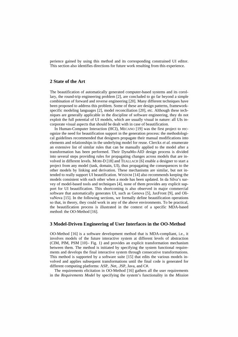
OO-Method [16] is a software development method that is MDA-compliant, i.e., it involves models of the future interactive system at different levels of abstraction (CIM, PIM, PSM [10]– Fig. 1) and provides an explicit transformation mechanism between them. The method is initiated by specifying the system functional require-ments and develops the final interactive system through consecutive transformations. This method is supported by a software suite [15] that edits the various models in-volved and applies subsequent transformations until the final code is generated for different computing platforms: ASP, .Net, .JSP, Java, and C#.
The requirements elicitation in OO-Method [16] gathers all the user requirements in the Requirements Model by specifying the system’s functionality in the Mission
Statement and the Function Refinement Tree. The Use Cases detail each function and when this model is complete, system specifications are output independently of the implementation or the technological space (Computation Independent Model - CIM).
Fig. 1. Correspondences between the MDA proposal and the OO-Method
The Conceptual Model, equivalent to the MDA’s Platform-Independent Model or-PIM, specifies four complementary system views. The Object Model specifies the static properties of the interactive application by defining the classes and their rela-tionships. The Dynamic Model controls the application objects by defining their life cycle and their interactions. The Functional Model describes the semantics of object’s state changes. Finally the Presentation Model (PM) models the UI.
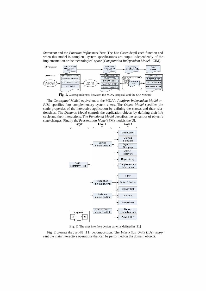
Fig. 2. The user interface design patterns defined in [11]
Fig. 2 presents the Just-UI [11] decomposition. The Interaction Units (IUs) repre-sent the main interactive operations that can be performed on the domain objects:
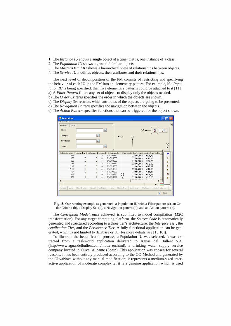
1. The Instance IU shows a single object at a time, that is, one instance of a class. 2. The Population IU shows a group of similar objects. 3. The Master/Detail IU shows a hierarchical view of relationships between objects. 4. The Service IU modifies objects, their attributes and their relationships.
The next level of decomposition of the PM consists of restricting and specifying the behavior of each IU in the PM into an elementary pattern. For example, if a Popu-lation IU is being specified, then five elementary patterns could be attached to it [11]: a) A Filter Pattern filters any set of objects to display only the objects needed. b) The Order Criteria specifies the order in which the objects are shown. c) The Display Set restricts which attributes of the objects are going to be presented. d) The Navigation Pattern specifies the navigation between the objects. e) The Action Pattern specifies functions that can be triggered for the object shown.
Fig. 3. Our running example as generated: a Population IU with a Filter pattern (a), an Or-der Criteria (b), a Display Set (c), a Navigation pattern (d), and an Action pattern (e).
The Conceptual Model, once achieved, is submitted to model compilation (M2C transformation). For any target computing platform, the Source Code is automatically generated and structured according to a three tier’s architecture: the Interface Tier, the Application Tier, and the Persistence Tier. A fully functional application can be gen-erated, which is not limited to database or UI (for more details, see [15,16]).
To illustrate the beautification process, a Population IU was selected. It was ex-tracted from a real-world application delivered to Aguas del Bullent S.A. (http://www.aguasdelbullent.com/index_en.html), a drinking water supply service company located in Oliva, Alicante (Spain). This application was chosen for several reasons: it has been entirely produced according to the OO-Method and generated by the OlivaNova without any manual modification; it represents a medium-sized inter-active application of moderate complexity; it is a genuine application which is used
today; and it has received the Microsoft certification of quality. Fig. 3 reproduces a Population pattern for displaying the water meters of customers located in a certain region. This Population pattern is decomposed into the five elementary patterns de-scribed above. The following section shows how this automatically generated UI is subjected to beautification operations.
4 The Beautification Process
4.1 Purpose of Beautification Operations The need for a beautification operation arises as soon as there are user requirements that are unsupported by the MDA approach. For example, users of the interface shown in Fig. 3 complain that the list of objects displayed may become long. To im-prove the legibility of the list, the background color was changed every four lines with a usable background color in order to avoid interfering with the data. Since this fea-ture is not supported by the approach there is no modeling operation for it and a man-ual modification is necessary. The goal now is to turn these manual modifications into beautification operations, which will ultimately be considered as modeling operations. To decide the manual modifications to be included into the beautification process, a statistical analysis was conducted on three professional applications generated by the OlivaNova software: 1. A small-sized interactive application: ProAM consists of a golf management appli-
cation especially designed for golf tournaments, which is generated for both JSP and Visual Basic. A total number of 19 manual modifications were observed.
2. A moderately-sized interactive application: MultiLanguage consists of an applica-tion that runs the same user interfaces but in different languages. It was generated for C# and a total amount of 144 manual modifications were reported.
3. A large-sized interactive application: Alligator consists of an invoicing system for multiple inter-related companies with advanced reporting functions, which is gen-erated in Visual Basic. A total of 252 manual modifications were examined. From the total of 415 manual modifications those made by the developers were ex-
tracted (171 out of 252 were considered in the large-sized application) and classified into two sets: those relevant to the Presentation Model (103 out of 171) and those not relevant to it (58 out of 171) but relevant to the other models involved in the OO-Method (Fig. 1). This study shows the most frequent modifications and their level of importance in terms of the impact on the generated code. Therefore, a manual modifi-cation is considered a beautification operation because: the operation was observed in most applications; the operation occurred with a significant frequency; the operation was realistic in terms of future implementation support; and the operation was of at least moderate importance.
4.2 Classification of Beautification Operations
In order to classify a manual operation and, therefore, a subsequent beautification op-eration, Nielsen’s linguistic model of interaction [13] was selected for these reasons: it decomposes a human-computer interaction in terms of seven inter-related, but inde-pendent, levels with a communication protocol between them; it has already been
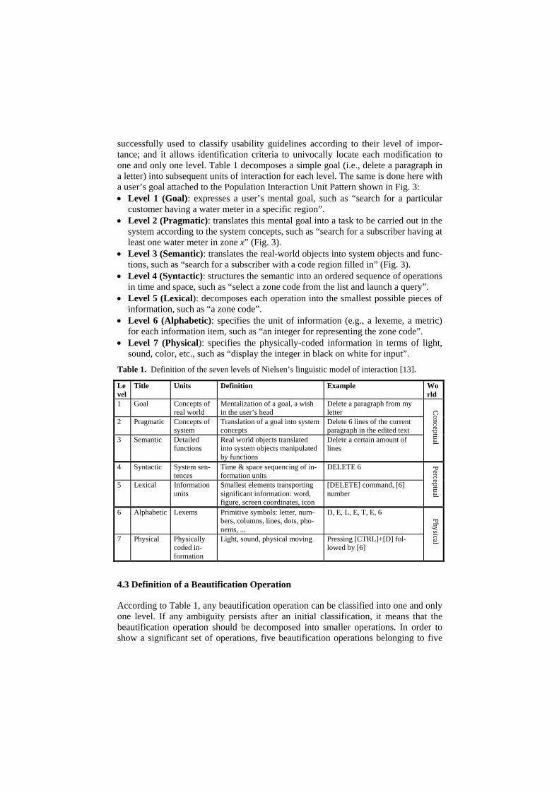
successfully used to classify usability guidelines according to their level of impor-tance; and it allows identification criteria to univocally locate each modification to one and only one level. Table 1 decomposes a simple goal (i.e., delete a paragraph in a letter) into subsequent units of interaction for each level. The same is done here with a user’s goal attached to the Population Interaction Unit Pattern shown in Fig. 3: • Level 1 (Goal): expresses a user’s mental goal, such as “search for a particular
customer having a water meter in a specific region”. • Level 2 (Pragmatic): translates this mental goal into a task to be carried out in the
system according to the system concepts, such as “search for a subscriber having at least one water meter in zone x” (Fig. 3).
• Level 3 (Semantic): translates the real-world objects into system objects and func-tions, such as “search for a subscriber with a code region filled in” (Fig. 3).
• Level 4 (Syntactic): structures the semantic into an ordered sequence of operations in time and space, such as “select a zone code from the list and launch a query”.
• Level 5 (Lexical): decomposes each operation into the smallest possible pieces of information, such as “a zone code”.
• Level 6 (Alphabetic): specifies the unit of information (e.g., a lexeme, a metric) for each information item, such as “an integer for representing the zone code”.
• Level 7 (Physical): specifies the physically-coded information in terms of light, sound, color, etc., such as “display the integer in black on white for input”.
Table 1. Definition of the seven levels of Nielsen’s linguistic model of interaction [13].
Level
Title Units Definition Example World
1 Goal Concepts of real world
Mentalization of a goal, a wish in the user’s head
Delete a paragraph from my letter
2 Pragmatic Concepts of system
Translation of a goal into system concepts
Delete 6 lines of the current paragraph in the edited text
3 Semantic Detailed functions
Real world objects translated into system objects manipulated by functions
Delete a certain amount of lines
Conceptual
4 Syntactic System sen-tences
Time & space sequencing of in-formation units
DELETE 6
5 Lexical Information units
Smallest elements transporting significant information: word, figure, screen coordinates, icon
[DELETE] command, [6] number
Perceptual
6 Alphabetic Lexems Primitive symbols: letter, num-bers, columns, lines, dots, pho-nems, ...
D, E, L, E, T, E, 6
7 Physical Physically coded in-formation
Light, sound, physical moving Pressing [CTRL]+[D] fol-lowed by [6]
Physical
4.3 Definition of a Beautification Operation
According to Table 1, any beautification operation can be classified into one and only one level. If any ambiguity persists after an initial classification, it means that the beautification operation should be decomposed into smaller operations. In order to show a significant set of operations, five beautification operations belonging to five
different levels will be executed for our running example (Fig. 3) as follows: 1. Level 7 (Physical): Specify (rowHighlightingType) specifies that for every n num-
ber of lines in a table, the background color of this line should be set to a color that is different from the foreground color to ensure contrast. For instance, in Fig. 3, one in every four lines of the “Subscriber table” should be highlighted. This opera-tion belongs to the Physical Level because it affects the physical appearance.
2. Level 6 (Alphabetical): Convert (inputMetricUnit, outputMetricUnit) converts data expressed according to one metric unit into another one. For instance, in Fig. 3, the currency of a price displayed in the column “Invoice amount” should be converted from the Euro (€) currency into the United States Dollar (U$D) cur-rency. This operation belongs to the Alphabetical Level because it only changes the numerical value of prices with another symbol to support internationalization.
3. Level 5 (Lexical): Specify (buttonPresentationType) specifies whether a push but-ton should be presented with one label only (l), with an icon only (i) or with both (i+l), according to the usability guideline. For instance, in Fig. 3, a push button of the navigation pattern (e) could be presented with an icon and label together. This operation belongs to the Lexical Level because textual and/or graphical informa-tion is presented for the same object.
4. Level 4 (Syntactical): Substitute (widgetType) replaces a widget of a given type by a widget of another type by transferring its properties from the initial one to the substituted one. For instance, in Fig. 3, the edit box attached to “Category” may be substituted by a drop-down combo box because the amount of categories remains fixed. This operation belongs to the Syntactical Level because it changes the se-quence of actions that the user has to do in order to select a category.
5. Level 3 (Semantic): Specify (conditionalDisplay) changes the value of a widget property depending on whether a semantic condition is satisfied or not. For in-stance, in Fig. 3, the “Invoiced” flag should be changed to another symbol depend-ing on whether the invoice has been issued or not. This operation belongs to the Semantic Level because the presentation only changes according to a semantic change of the object (that is, the values of its attributes).
These five examples show that a beautification operation is executed depending on the widget types involved, the interaction unit concerned, and the elementary patterns present. Therefore, a beautification operation is now formally defined as a State-Pair Action (SAP) B = ⟨ s, a ⟩ where
s = a state of a IU where the beautification operation could be applied. a = an action to be performed on the state s when it is found.
A SAP consists of a representation of the Interaction Units (IUs) contents prior to executing the action (the state) and a description of this action at an appropriate level of abstraction (the action). Consequently, these five examples of beautification opera-tions could be formally expressed as follows:
B1 = ⟨ table in: DisplaySet, Specify (rowHighlightingType) ⟩ B2 = ⟨ cell in:table in: DisplaySet, Convert (inputMetricUnit, outputMetricUnit) ⟩ B3 = ⟨ button in:Navigation in: PopulationIU, Specify (buttonPresentationType) ⟩ B4 = ⟨ inputText in:, Substitute (widgetType) ⟩
B5 = ⟨ cell in:, Specify (conditionalDisplay) ⟩
If the same beautification operation is applied on different widgets considered in different contexts, the beautification operation is repeated with the same action. De-pending on the scope of the action and depending on what needs to be beautified, the action could be applied on a particular widget, on a particular widget in a container, or to a series of widgets.
Now that a beautification operation has been properly defined, the next section de-scribes the beautification process and then decomposes this process into three steps.
4.4 The Steps of the Beautification Process
Thanks to the concept of beautification, OO-Method methodology can be improved through beautification (Fig. 4). This process is decomposed into three steps which are detailed in the following subsections.
Step 1: Derivation of a Concrete User Interface Model from the Presentation Model. Since the Presentation Model contains an abstract definition of the future UI in terms of IUs and attached elementary patterns, it is considered to be the best candi-date to apply a M2M transformation in order to derive a Concrete User Interface Model from it. This model needs to fulfill at least two requirements: 1. In order to apply any beautification operation, it is necessary to know which widget
must be replaced depending on the context. 2. In order to manipulate a working model, an internal UI representation that is sub-
ject to the beautification operations must be maintained.
The Concrete User Interface (CUI) model of the USer Interface eXtensible markup Language (UsiXML – http://www.usixml.org) has been selected because it satisfies these two requirements and allows us to provide the following definitions: • A Concrete User Interface (CUI) consists of an abstraction of a final UI independ-
ently of the particular widgets used in a particular computing platform, thus result-ing in a characterization of a UI in terms of Concrete Interaction Objects (CIOs). In this paper only graphical CIOs will be considered.
• Let C be the set of all graphical CIOs to be considered here. • A graphical CIO, or a CIO for short here, is formally defined as a couple c = ⟨t,A⟩
- where t = type of the CIO A = decorator iff c is non-interactive, graphicalIndi-vidualComponent iff c is interactive and ∃/ c’ ∈ C such that c’ ⊂ c, graphical-Container iff c is interactive and ∃ c’ ∈ C such that c’ ⊂ c, respectively.
- where A is a set of triple (ai, ti, vi): A = { (ai, ti, vi) }, of cardinality ⎪A⎪ = n where i.ai (i=1,…,n) = ith attribute of c
ii.ti (i=1,…,n) = data type of the ith attribute of c : ti ∈ {boolean, time, date, inte-ger, string}
iii.vi (i=1,…,n) = value of the ith attribute of c = null if ai is empty • Therefore C = {decorators, graphicalIndividualComponent, graphicalContainer} • UsiXML includes several CIOs for these different types, such as: a separator
(decorator), inputText, outputText, radioButton, checkBox, listBox (graphicalIndi-vidualComponent), dialogBox, window, and tabbedDialogBox (containers).
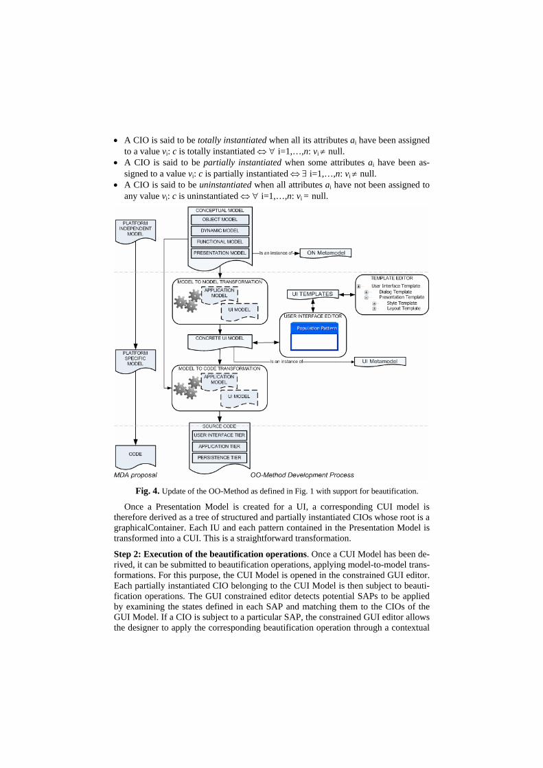
• A CIO is said to be totally instantiated when all its attributes ai have been assigned to a value vi: c is totally instantiated ⇔ ∀ i=1,…,n: vi ≠ null.
• A CIO is said to be partially instantiated when some attributes ai have been as-signed to a value vi: c is partially instantiated ⇔ ∃ i=1,…,n: vi ≠ null.
• A CIO is said to be uninstantiated when all attributes ai have not been assigned to any value vi: c is uninstantiated ⇔ ∀ i=1,…,n: vi = null.
Fig. 4. Update of the OO-Method as defined in Fig. 1 with support for beautification.
Once a Presentation Model is created for a UI, a corresponding CUI model is therefore derived as a tree of structured and partially instantiated CIOs whose root is a graphicalContainer. Each IU and each pattern contained in the Presentation Model is transformed into a CUI. This is a straightforward transformation.
Step 2: Execution of the beautification operations. Once a CUI Model has been de-rived, it can be submitted to beautification operations, applying model-to-model trans-formations. For this purpose, the CUI Model is opened in the constrained GUI editor. Each partially instantiated CIO belonging to the CUI Model is then subject to beauti-fication operations. The GUI constrained editor detects potential SAPs to be applied by examining the states defined in each SAP and matching them to the CIOs of the GUI Model. If a CIO is subject to a particular SAP, the constrained GUI editor allows the designer to apply the corresponding beautification operation through a contextual
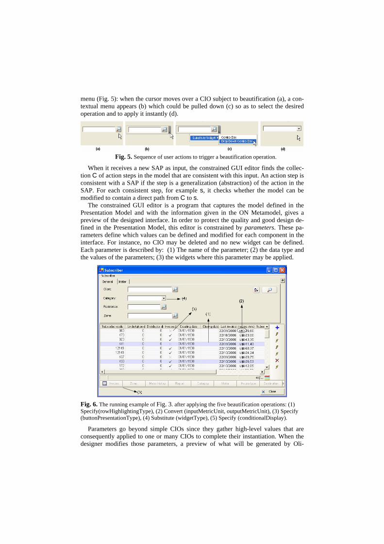
menu (Fig. 5): when the cursor moves over a CIO subject to beautification (a), a con-textual menu appears (b) which could be pulled down (c) so as to select the desired operation and to apply it instantly (d).
Fig. 5. Sequence of user actions to trigger a beautification operation.
When it receives a new SAP as input, the constrained GUI editor finds the collec-tion C of action steps in the model that are consistent with this input. An action step is consistent with a SAP if the step is a generalization (abstraction) of the action in the SAP. For each consistent step, for example s, it checks whether the model can be modified to contain a direct path from C to s.
The constrained GUI editor is a program that captures the model defined in the Presentation Model and with the information given in the ON Metamodel, gives a preview of the designed interface. In order to protect the quality and good design de-fined in the Presentation Model, this editor is constrained by parameters. These pa-rameters define which values can be defined and modified for each component in the interface. For instance, no CIO may be deleted and no new widget can be defined. Each parameter is described by: (1) The name of the parameter; (2) the data type and the values of the parameters; (3) the widgets where this parameter may be applied.
Fig. 6. The running example of Fig. 3. after applying the five beautification operations: (1) Specify(rowHighlightingType), (2) Convert (inputMetricUnit, outputMetricUnit), (3) Specify (buttonPresentationType), (4) Substitute (widgetType), (5) Specify (conditionalDisplay).
Parameters go beyond simple CIOs since they gather high-level values that are consequently applied to one or many CIOs to complete their instantiation. When the designer modifies those parameters, a preview of what will be generated by Oli-
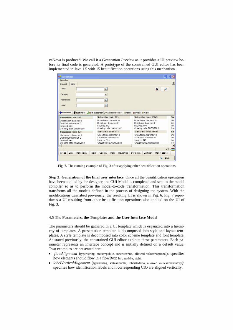
vaNova is produced. We call it a Generation Preview as it provides a UI preview be-fore its final code is generated. A prototype of the constrained GUI editor has been implemented in Java 1.5 with 15 beautification operations using this mechanism.
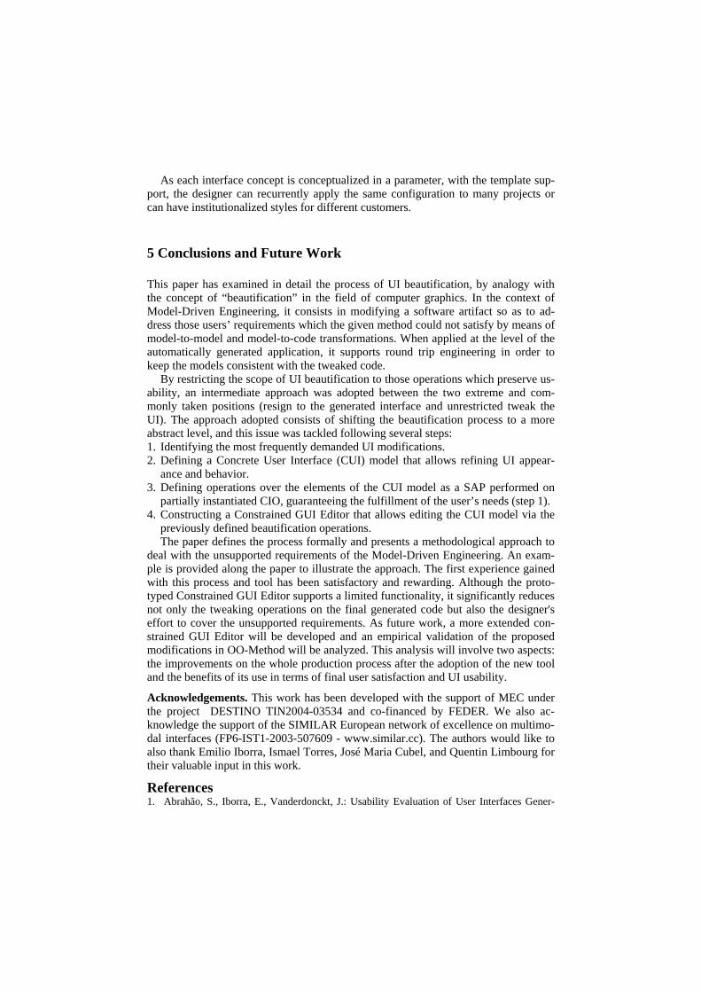
Fig. 7. The running example of Fig. 3 after applying other beautification operations
Step 3: Generation of the final user interface. Once all the beautification operations have been applied by the designer, the CUI Model is completed and sent to the model compiler so as to perform the model-to-code transformation. This transformation transforms all the models defined in the process of designing the system. With the modifications described previously, the resulting UI is shown in Fig. 6. Fig. 7 repro-duces a UI resulting from other beautification operations also applied on the UI of Fig. 3.
4.5 The Parameters, the Templates and the User Interface Model
The parameters should be gathered in a UI template which is organized into a hierar-chy of templates. A presentation template is decomposed into style and layout tem-plates. A style template is decomposed into color scheme template and font template. As stated previously, the constrained GUI editor exploits these parameters. Each pa-rameter represents an interface concept and is initially defined on a default value. Two examples are presented here: • flowAlignment (type=string, status=public, inherited=no, allowed values=optional): specifies
how elements should flow in a flowBox: left, middle, right. • labelVerticalAlignment (type=string, status=public, inherited=no, allowed values=mandatory):
specifies how identification labels and it corresponding CIO are aligned vertically.
As each interface concept is conceptualized in a parameter, with the template sup-port, the designer can recurrently apply the same configuration to many projects or can have institutionalized styles for different customers.
5 Conclusions and Future Work
This paper has examined in detail the process of UI beautification, by analogy with the concept of “beautification” in the field of computer graphics. In the context of Model-Driven Engineering, it consists in modifying a software artifact so as to ad-dress those users’ requirements which the given method could not satisfy by means of model-to-model and model-to-code transformations. When applied at the level of the automatically generated application, it supports round trip engineering in order to keep the models consistent with the tweaked code.
By restricting the scope of UI beautification to those operations which preserve us-ability, an intermediate approach was adopted between the two extreme and com-monly taken positions (resign to the generated interface and unrestricted tweak the UI). The approach adopted consists of shifting the beautification process to a more abstract level, and this issue was tackled following several steps: 1. Identifying the most frequently demanded UI modifications. 2. Defining a Concrete User Interface (CUI) model that allows refining UI appear-
ance and behavior. 3. Defining operations over the elements of the CUI model as a SAP performed on
partially instantiated CIO, guaranteeing the fulfillment of the user’s needs (step 1). 4. Constructing a Constrained GUI Editor that allows editing the CUI model via the
previously defined beautification operations. The paper defines the process formally and presents a methodological approach to
deal with the unsupported requirements of the Model-Driven Engineering. An exam-ple is provided along the paper to illustrate the approach. The first experience gained with this process and tool has been satisfactory and rewarding. Although the proto-typed Constrained GUI Editor supports a limited functionality, it significantly reduces not only the tweaking operations on the final generated code but also the designer's effort to cover the unsupported requirements. As future work, a more extended con-strained GUI Editor will be developed and an empirical validation of the proposed modifications in OO-Method will be analyzed. This analysis will involve two aspects: the improvements on the whole production process after the adoption of the new tool and the benefits of its use in terms of final user satisfaction and UI usability.
Acknowledgements. This work has been developed with the support of MEC under the project DESTINO TIN2004-03534 and co-financed by FEDER. We also ac-knowledge the support of the SIMILAR European network of excellence on multimo-dal interfaces (FP6-IST1-2003-507609 - www.similar.cc). The authors would like to also thank Emilio Iborra, Ismael Torres, José Maria Cubel, and Quentin Limbourg for their valuable input in this work.
References 1. Abrahão, S., Iborra, E., Vanderdonckt, J.: Usability Evaluation of User Interfaces Gener-
ated with a Model-Driven Architecture Tool. Chapter 2. In: Law, E., Hvannberg, E., Cock-ton, G. (eds): Maturing Usability: Quality in Software, Interaction and Value. HCI Series, Springer-Verlag, Berlin (2007)
2. Antkiewicz, M.: Round-Trip Engineering of Framework-Based Software using Framework-Specific Modeling Languages. In: Proc. of ASE’2006
3. Clerckx, T., Luyten, K., Coninx, K.: The Mapping Problem Back and Forth: Customizing Dynamic Models while preserving Consistency. In: Proc. of TAMODIA’2004 (Prague, November 15-16, 2004). ACM Int. Series, Vol. 86. ACM Press, New York (2004) 33–42
4. da Silva, P.P.: User Interface Declarative Models and Development Environments: A Sur-vey. In: Proc. of 7th Int. Workshop on Design, Specification, and Verification of Interactive Systems DSV-IS’2000 (Limerick, June 5-6, 2000). Lecture Notes in Computer Science, Vol. 1946. Springer-Verlag, Berlin (2000) 207–226
5. Genova V8.0, Esito AS, Lysaker (2006), http://www.genera.no/default.htm 6. Griffiths, T., Barclay, P.J., Paton, N.W., McKirdy, J., Kennedy, J.B., Gray, P.D., Cooper,
R., Goble, C.A., da Silva, P.P.: Teallach: a Model-Based User Interface Development Envi-ronment for Object Databases. Interacting with Computers 14,1 (December 2001) 31–68
7. Hall, A., Chapman, R.: Correctness by Construction: Developing a Commercial Secure System. IEEE Software 19,1 (2002) 18–25
8. Igarashi, T., Matsuoka, S., Kawachiya, S., Tanaka, H.: Interactive Beautification: a Tech-nique for Rapid Geometric Design. In: Proc. of the 10th Annual ACM Symposium on User Interface Software and Technology UIST’97. ACM Press, New York (1997) 105–114
9. JaxFront, XCentric Technology & Consulting GmbH, Zurich (2006), http://www.jaxfront. org/pages/
10. Model-Driven Architecture Guide, Version 1.0.1, Object Management Group (December 2006), http://www.omg.org/docs/omg/03-06-01.pdf
11. Molina, P.J., Meliá, S., Pastor, O.: JUST-UI: A User Interface Specification Model. In: Proc. of 4th Int. Conf. on Computer-Aided Design of User Interfaces CADUI’2002 (Valen-ciennes, May 2002). Kluwer Academic Press, Dordrecht (2002) 63–74
12. Myers, B., Hudson, S.E., Pausch, R.: Past, Present, and Future of User Interface Software Tools. ACM Trans. Computer-Human Interaction 7,1 (2000) 3–28
13. Nielsen, J.: A Virtual Protocol Model for Computer-Human Interaction. International Jour-nal of Man-Machine Studies 24,3 (1986) 301–312
14. Nunes, N.J., Falcao e Cunha, J.: WISDOM - A UML-Based Architecture for Interactive Sys-tems. In: Proc. of DSV-IS’2000 (Limerick, June 5-6, 2000). Lecture Notes in Computer Science, Vol. 1946. Springer-Verlag, Berlin (2000) 191–205
15. OlivaNova Software, Care Technologies, Denia (December 2006), http://www.care-t.com 16. Pastor, O., Gómez, J., Insfrán, E., Pelechano, V.: The OO-Method Approach for Informa-
tion Systems Modeling: from Object-oriented Conceptual Modeling to Automated Pro-gramming. Information Systems 26,7 (2001) 507–534
17. Pavlidis, T., Van Wyk, C.J.V.: An Automatic Beautifier for Drawings and Illustrations. Computer Graphics 19,3 (July 1985) 225–234
18. Puerta, A.R., A Model-Based Interface Development Environment. IEEE Software, 14,4 (1997) 40–47
19. Puerta, A.R., Eriksson, H., Gennari, J.H., Musen, M.A.: Beyond Data Models for Auto-mated User Interface Generation. In Proc. of HCI’94 Glasgow, September 1994). Cam-bridge University Press, New York (2004) 353–366
20. Sendall, S., Küster, J.: Taming Model Round-Trip Engineering. In: Proc. of Workshop ’Best Practices for Model-Driven Software Development’ MDSD’2004 (Vancouver, Octo-ber 2004).
21. Vanderdonckt, J.: A MDA-Compliant Environment for Developing User Interfaces of In-formation Systems. In: Proc. of CAiSE’2005. LNCS, Vol. 3520. Springer-Verlag, 16–31.


![Computational Photography - TU Wien · 7 Beautification [Deussen et al.] DataData--Driven Enhancement Driven Enhancement of Facial Attractiveness Tommer Leyvand, Daniel Cohen-Or,](https://img.pdfslide.us/doc/110x75/5b80fcee7f8b9aeb088e75cc/computational-photography-tu-wien-7-beautification-deussen-et-al-datadata-driven.jpg)