Embed Size (px)
Citation preview
Preprint typeset in JINST style - HYPER VERSION
The artificial retina processor for trackreconstruction at the LHC crossing rate
A. Abbaa, F. Bedeschib, M. Citterioa, F. Caponioa, A. Cusimanoa, A. Geracia,P. Marinob, M.J. Morellob, N. Neria, G. Punzib, A. Piuccib, L. Ristorib,c, F. Spinellab,S. Strackab, and D. Tonellid∗
a Politecnico and INFN, Milano,Via Celoria 16, 20133 Milano, Italy
b University, Scuola Normale Superiore, and INFN Pisa,Largo Pontecorvo 3, 56127 Pisa, Italy
c Fermilab,PO Box 500, 60510 Batavia, IL, U.S.A.
d CERN,CH-1211 Geneva 23, Switzerland
E-mail: [email protected]
ABSTRACT: We present results of an R&D study for a specialized processor capable of preciselyreconstructing, in pixel detectors, hundreds of charged-particle tracks from high-energy collisionsat 40 MHz rate. We apply a highly parallel pattern-recognition algorithm, inspired by studies of theprocessing of visual images by the brain as it happens in nature, and describe in detail an efficienthardware implementation in high-speed, high-bandwidth FPGA devices. This is the first detaileddemonstration of reconstruction of offline-quality tracks at 40 MHz and makes the device suitablefor processing Large Hadron Collider events at the full crossing frequency.
KEYWORDS: Pattern recognition; trigger; real-time tracking; FPGA.
∗Corresponding author.
arX
iv:1
409.
1565
v4 [
phys
ics.
ins-
det]
4 D
ec 2
014
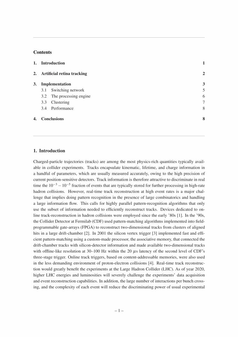
Contents
1. Introduction 1
2. Artificial retina tracking 2
3. Implementation 33.1 Switching network 53.2 The processing engine 63.3 Clustering 73.4 Performance 8
4. Conclusions 8
1. Introduction
Charged-particle trajectories (tracks) are among the most physics-rich quantities typically avail-able in collider experiments. Tracks encapsulate kinematic, lifetime, and charge information ina handful of parameters, which are usually measured accurately, owing to the high precision ofcurrent position-sensitive detectors. Track information is therefore attractive to discriminate in realtime the 10−3 −10−5 fraction of events that are typically stored for further processing in high-ratehadron collisions. However, real-time track reconstruction at high event rates is a major chal-lenge that implies doing pattern recognition in the presence of large combinatorics and handlinga large information flow. This calls for highly parallel pattern-recognition algorithms that onlyuse the subset of information needed to efficiently reconstruct tracks. Devices dedicated to on-line track-reconstruction in hadron collisions were employed since the early ’80s [1]. In the ’90s,the Collider Detector at Fermilab (CDF) used pattern-matching algorithms implemented into field-programmable gate-arrays (FPGA) to reconstruct two-dimensional tracks from clusters of alignedhits in a large drift-chamber [2]. In 2001 the silicon vertex trigger [3] implemented fast and effi-cient pattern-matching using a custom-made processor, the associative memory, that connected thedrift-chamber tracks with silicon-detector information and made available two-dimensional trackswith offline-like resolution at 30–100 Hz within the 20 µs latency of the second level of CDF’sthree-stage trigger. Online track triggers, based on content-addressable memories, were also usedin the less demanding environment of proton-electron collisions [4]. Real-time track reconstruc-tion would greatly benefit the experiments at the Large Hadron Collider (LHC). As of year 2020,higher LHC energies and luminosities will severely challenge the experiments’ data acquisitionand event reconstruction capabilities. In addition, the large number of interactions per bunch cross-ing, and the complexity of each event will reduce the discriminating power of usual experimental
– 1 –
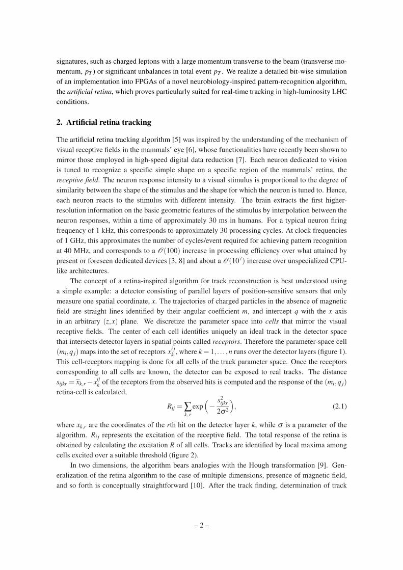
signatures, such as charged leptons with a large momentum transverse to the beam (transverse mo-mentum, pT ) or significant unbalances in total event pT . We realize a detailed bit-wise simulationof an implementation into FPGAs of a novel neurobiology-inspired pattern-recognition algorithm,the artificial retina, which proves particularly suited for real-time tracking in high-luminosity LHCconditions.
2. Artificial retina tracking
The artificial retina tracking algorithm [5] was inspired by the understanding of the mechanism ofvisual receptive fields in the mammals’ eye [6], whose functionalities have recently been shown tomirror those employed in high-speed digital data reduction [7]. Each neuron dedicated to visionis tuned to recognize a specific simple shape on a specific region of the mammals’ retina, thereceptive field. The neuron response intensity to a visual stimulus is proportional to the degree ofsimilarity between the shape of the stimulus and the shape for which the neuron is tuned to. Hence,each neuron reacts to the stimulus with different intensity. The brain extracts the first higher-resolution information on the basic geometric features of the stimulus by interpolation between theneuron responses, within a time of approximately 30 ms in humans. For a typical neuron firingfrequency of 1 kHz, this corresponds to approximately 30 processing cycles. At clock frequenciesof 1 GHz, this approximates the number of cycles/event required for achieving pattern recognitionat 40 MHz, and corresponds to a O(100) increase in processing efficiency over what attained bypresent or foreseen dedicated devices [3, 8] and about a O(107) increase over unspecialized CPU-like architectures.
The concept of a retina-inspired algorithm for track reconstruction is best understood usinga simple example: a detector consisting of parallel layers of position-sensitive sensors that onlymeasure one spatial coordinate, x. The trajectories of charged particles in the absence of magneticfield are straight lines identified by their angular coefficient m, and intercept q with the x axisin an arbitrary (z,x) plane. We discretize the parameter space into cells that mirror the visualreceptive fields. The center of each cell identifies uniquely an ideal track in the detector spacethat intersects detector layers in spatial points called receptors. Therefore the parameter-space cell(mi,q j) maps into the set of receptors xi j
k , where k = 1, . . . ,n runs over the detector layers (figure 1).This cell-receptors mapping is done for all cells of the track parameter space. Once the receptorscorresponding to all cells are known, the detector can be exposed to real tracks. The distancesijkr = xk,r −xij
k of the receptors from the observed hits is computed and the response of the (mi,q j)
retina-cell is calculated,
Rij = ∑k,r
exp(−
s2ijkr
2σ2
), (2.1)
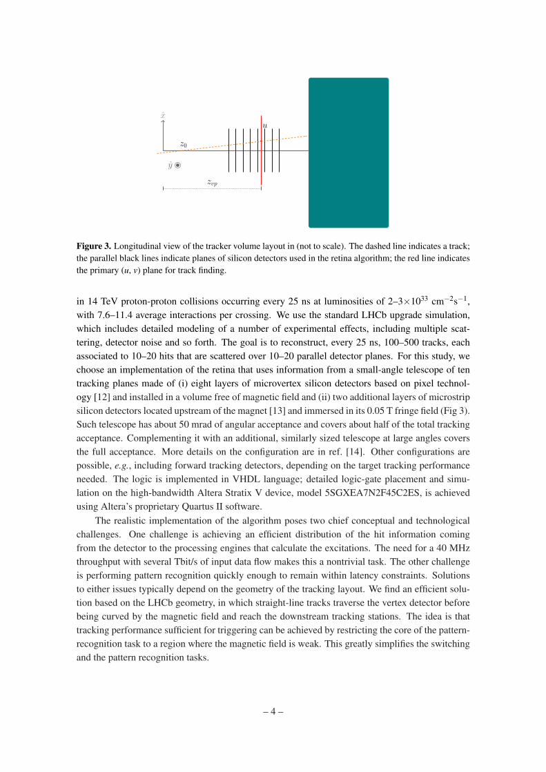
where xk,r are the coordinates of the rth hit on the detector layer k, while σ is a parameter of thealgorithm. Ri j represents the excitation of the receptive field. The total response of the retina isobtained by calculating the excitation R of all cells. Tracks are identified by local maxima amongcells excited over a suitable threshold (figure 2).
In two dimensions, the algorithm bears analogies with the Hough transformation [9]. Gen-eralization of the retina algorithm to the case of multiple dimensions, presence of magnetic field,and so forth is conceptually straightforward [10]. After the track finding, determination of track
– 2 –
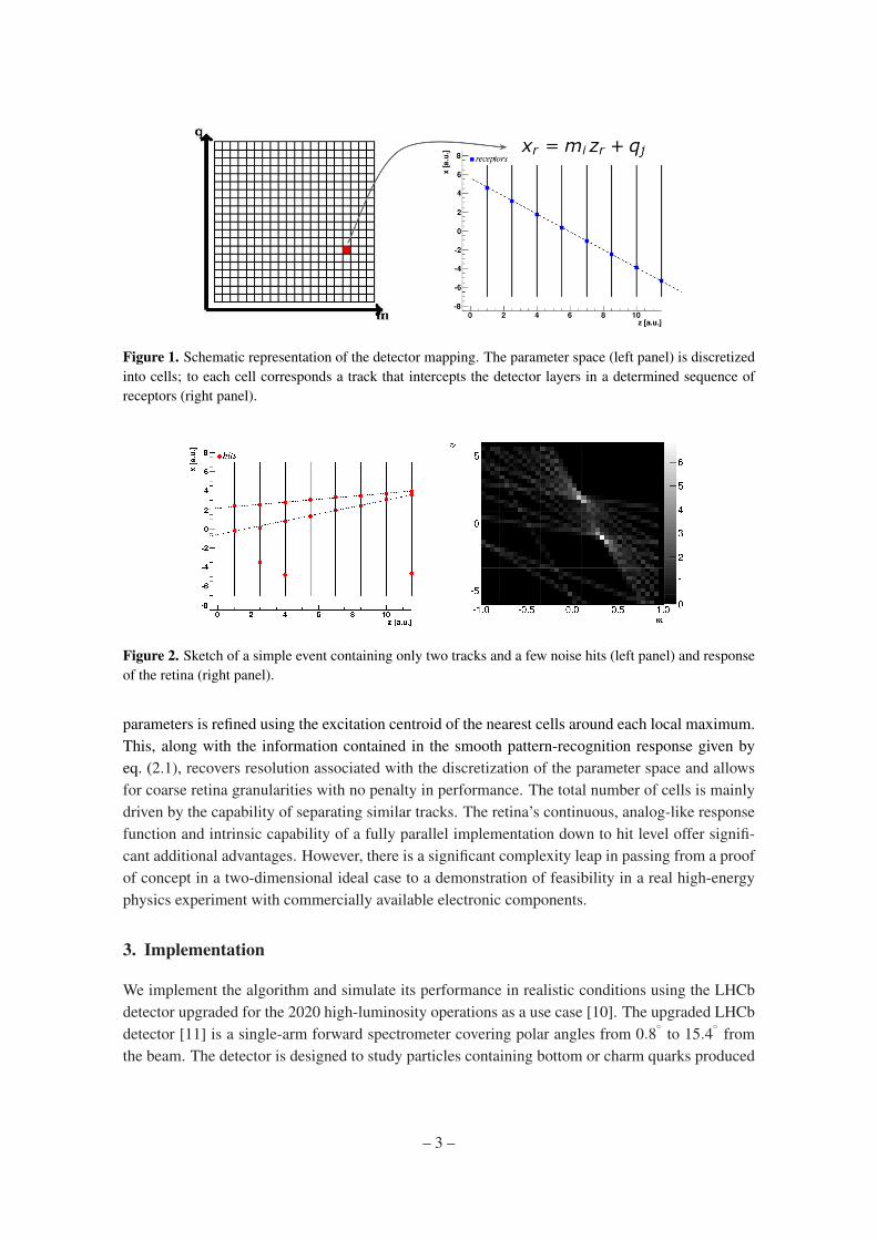
Figure 1. Schematic representation of the detector mapping. The parameter space (left panel) is discretizedinto cells; to each cell corresponds a track that intercepts the detector layers in a determined sequence ofreceptors (right panel).
Figure 2. Sketch of a simple event containing only two tracks and a few noise hits (left panel) and responseof the retina (right panel).
parameters is refined using the excitation centroid of the nearest cells around each local maximum.This, along with the information contained in the smooth pattern-recognition response given byeq. (2.1), recovers resolution associated with the discretization of the parameter space and allowsfor coarse retina granularities with no penalty in performance. The total number of cells is mainlydriven by the capability of separating similar tracks. The retina’s continuous, analog-like responsefunction and intrinsic capability of a fully parallel implementation down to hit level offer signifi-cant additional advantages. However, there is a significant complexity leap in passing from a proofof concept in a two-dimensional ideal case to a demonstration of feasibility in a real high-energyphysics experiment with commercially available electronic components.
3. Implementation
We implement the algorithm and simulate its performance in realistic conditions using the LHCbdetector upgraded for the 2020 high-luminosity operations as a use case [10]. The upgraded LHCbdetector [11] is a single-arm forward spectrometer covering polar angles from 0.8
◦to 15.4
◦from
the beam. The detector is designed to study particles containing bottom or charm quarks produced
– 3 –
x
z
u
z0
zvp
k
y ~B
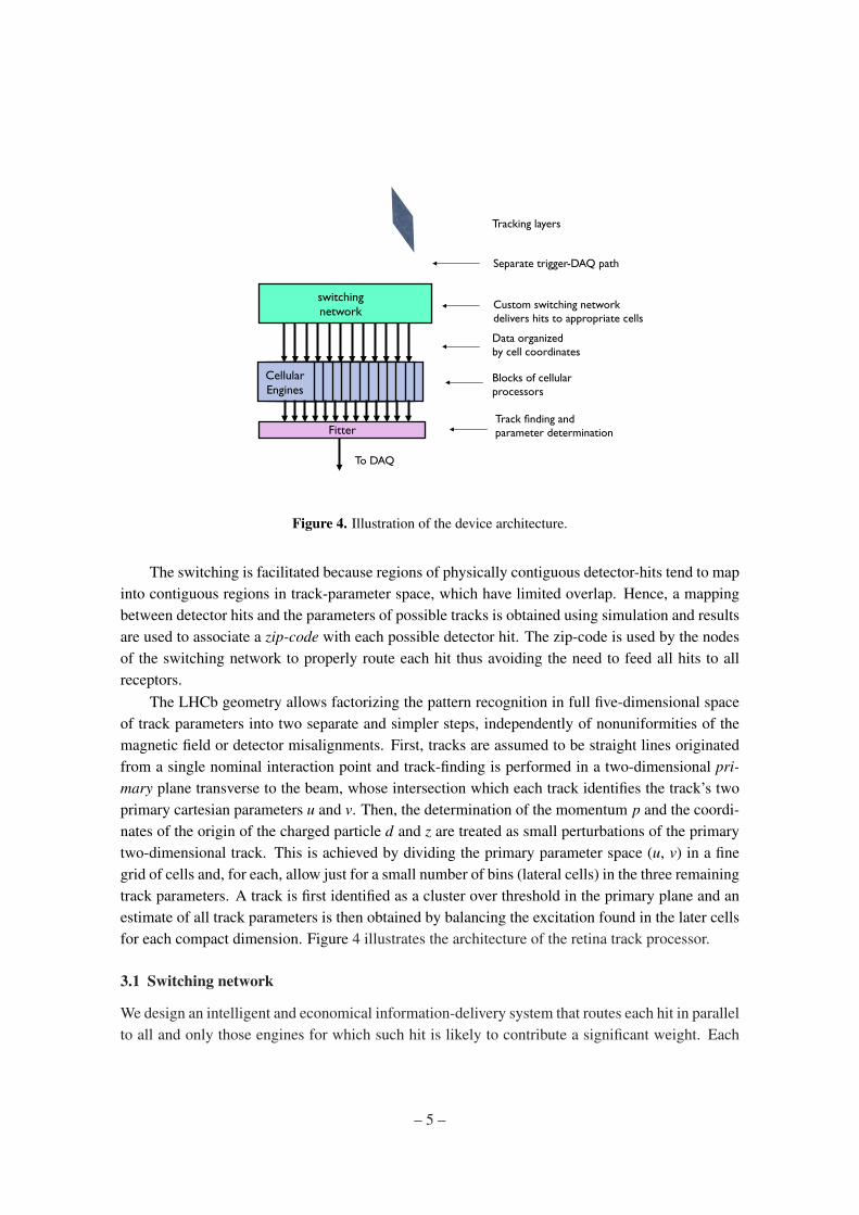
Figure 3. Longitudinal view of the tracker volume layout in (not to scale). The dashed line indicates a track;the parallel black lines indicate planes of silicon detectors used in the retina algorithm; the red line indicatesthe primary (u, v) plane for track finding.
in 14 TeV proton-proton collisions occurring every 25 ns at luminosities of 2–3×1033 cm−2s−1,with 7.6–11.4 average interactions per crossing. We use the standard LHCb upgrade simulation,which includes detailed modeling of a number of experimental effects, including multiple scat-tering, detector noise and so forth. The goal is to reconstruct, every 25 ns, 100–500 tracks, eachassociated to 10–20 hits that are scattered over 10–20 parallel detector planes. For this study, wechoose an implementation of the retina that uses information from a small-angle telescope of tentracking planes made of (i) eight layers of microvertex silicon detectors based on pixel technol-ogy [12] and installed in a volume free of magnetic field and (ii) two additional layers of microstripsilicon detectors located upstream of the magnet [13] and immersed in its 0.05 T fringe field (Fig 3).Such telescope has about 50 mrad of angular acceptance and covers about half of the total trackingacceptance. Complementing it with an additional, similarly sized telescope at large angles coversthe full acceptance. More details on the configuration are in ref. [14]. Other configurations arepossible, e.g., including forward tracking detectors, depending on the target tracking performanceneeded. The logic is implemented in VHDL language; detailed logic-gate placement and simu-lation on the high-bandwidth Altera Stratix V device, model 5SGXEA7N2F45C2ES, is achievedusing Altera’s proprietary Quartus II software.
The realistic implementation of the algorithm poses two chief conceptual and technologicalchallenges. One challenge is achieving an efficient distribution of the hit information comingfrom the detector to the processing engines that calculate the excitations. The need for a 40 MHzthroughput with several Tbit/s of input data flow makes this a nontrivial task. The other challengeis performing pattern recognition quickly enough to remain within latency constraints. Solutionsto either issues typically depend on the geometry of the tracking layout. We find an efficient solu-tion based on the LHCb geometry, in which straight-line tracks traverse the vertex detector beforebeing curved by the magnetic field and reach the downstream tracking stations. The idea is thattracking performance sufficient for triggering can be achieved by restricting the core of the pattern-recognition task to a region where the magnetic field is weak. This greatly simplifies the switchingand the pattern recognition tasks.
– 4 –
Cellular Engines
switching network
Fitter
Tracking layers
Separate trigger-DAQ path
Custom switching network delivers hits to appropriate cells
Data organized by cell coordinates
Blocks of cellular processors
Track finding and parameter determination
To DAQ
Figure 4. Illustration of the device architecture.
The switching is facilitated because regions of physically contiguous detector-hits tend to mapinto contiguous regions in track-parameter space, which have limited overlap. Hence, a mappingbetween detector hits and the parameters of possible tracks is obtained using simulation and resultsare used to associate a zip-code with each possible detector hit. The zip-code is used by the nodesof the switching network to properly route each hit thus avoiding the need to feed all hits to allreceptors.
The LHCb geometry allows factorizing the pattern recognition in full five-dimensional spaceof track parameters into two separate and simpler steps, independently of nonuniformities of themagnetic field or detector misalignments. First, tracks are assumed to be straight lines originatedfrom a single nominal interaction point and track-finding is performed in a two-dimensional pri-mary plane transverse to the beam, whose intersection which each track identifies the track’s twoprimary cartesian parameters u and v. Then, the determination of the momentum p and the coordi-nates of the origin of the charged particle d and z are treated as small perturbations of the primarytwo-dimensional track. This is achieved by dividing the primary parameter space (u, v) in a finegrid of cells and, for each, allow just for a small number of bins (lateral cells) in the three remainingtrack parameters. A track is first identified as a cluster over threshold in the primary plane and anestimate of all track parameters is then obtained by balancing the excitation found in the later cellsfor each compact dimension. Figure 4 illustrates the architecture of the retina track processor.
3.1 Switching network
We design an intelligent and economical information-delivery system that routes each hit in parallelto all and only those engines for which such hit is likely to contribute a significant weight. Each
– 5 –
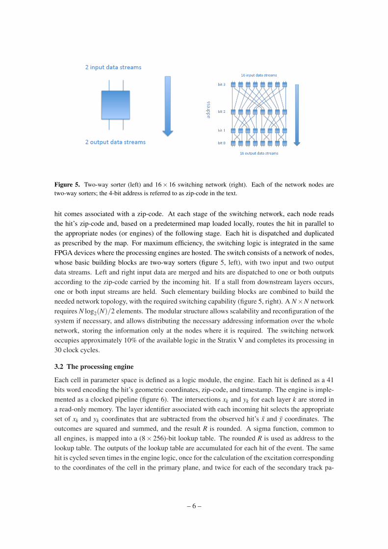
Figure 5. Two-way sorter (left) and 16× 16 switching network (right). Each of the network nodes aretwo-way sorters; the 4-bit address is referred to as zip-code in the text.
hit comes associated with a zip-code. At each stage of the switching network, each node readsthe hit’s zip-code and, based on a predetermined map loaded locally, routes the hit in parallel tothe appropriate nodes (or engines) of the following stage. Each hit is dispatched and duplicatedas prescribed by the map. For maximum efficiency, the switching logic is integrated in the sameFPGA devices where the processing engines are hosted. The switch consists of a network of nodes,whose basic building blocks are two-way sorters (figure 5, left), with two input and two outputdata streams. Left and right input data are merged and hits are dispatched to one or both outputsaccording to the zip-code carried by the incoming hit. If a stall from downstream layers occurs,one or both input streams are held. Such elementary building blocks are combined to build theneeded network topology, with the required switching capability (figure 5, right). A N×N networkrequires N log2(N)/2 elements. The modular structure allows scalability and reconfiguration of thesystem if necessary, and allows distributing the necessary addressing information over the wholenetwork, storing the information only at the nodes where it is required. The switching networkoccupies approximately 10% of the available logic in the Stratix V and completes its processing in30 clock cycles.
3.2 The processing engine
Each cell in parameter space is defined as a logic module, the engine. Each hit is defined as a 41bits word encoding the hit’s geometric coordinates, zip-code, and timestamp. The engine is imple-mented as a clocked pipeline (figure 6). The intersections xk and yk for each layer k are stored ina read-only memory. The layer identifier associated with each incoming hit selects the appropriateset of xk and yk coordinates that are subtracted from the observed hit’s x and y coordinates. Theoutcomes are squared and summed, and the result R is rounded. A sigma function, common toall engines, is mapped into a (8× 256)-bit lookup table. The rounded R is used as address to thelookup table. The outputs of the lookup table are accumulated for each hit of the event. The samehit is cycled seven times in the engine logic, once for the calculation of the excitation correspondingto the coordinates of the cell in the primary plane, and twice for each of the secondary track pa-
– 6 –
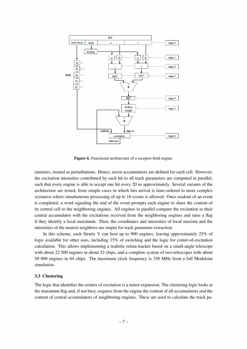
Figure 6. Functional architecture of a receptor-field engine.
rameters, treated as perturbations. Hence, seven accumulators are defined for each cell. However,the excitation intensities contributed by each hit to all track parameters are computed in parallel,such that every engine is able to accept one hit every 20 ns approximately. Several variants of thearchitecture are tested, from simple cases in which hits arrival is time-ordered to more complexscenarios where simultaneous processing of up to 16 events is allowed. Once readout of an eventis completed, a word signaling the end of the event prompts each engine to share the content ofits central cell to the neighboring engines. All engines in parallel compare the excitation in theircentral accumulator with the excitations received from the neighboring engines and raise a flagif they identify a local maximum. Then, the coordinates and intensities of local maxima and theintensities of the nearest neighbors are output for track parameter extraction.
In this scheme, each Stratix V can host up to 900 engines, leaving approximately 25% oflogic available for other uses, including 15% of switching and the logic for center-of-excitationcalculation. This allows implementing a realistic retina-tracker based on a small-angle telescopewith about 22 500 engines in about 32 chips, and a complete system of two-telescopes with about50 000 engines in 64 chips. The maximum clock frequency is 350 MHz from a full Modelsimsimulation.
3.3 Clustering
The logic that identifies the centers of excitation is a minor expansion. The clustering logic looks atthe maximum flag and, if not busy, requires from the engine the content of all accumulators and thecontent of central accumulators of neighboring engines. These are used to calculate the track pa-
– 7 –
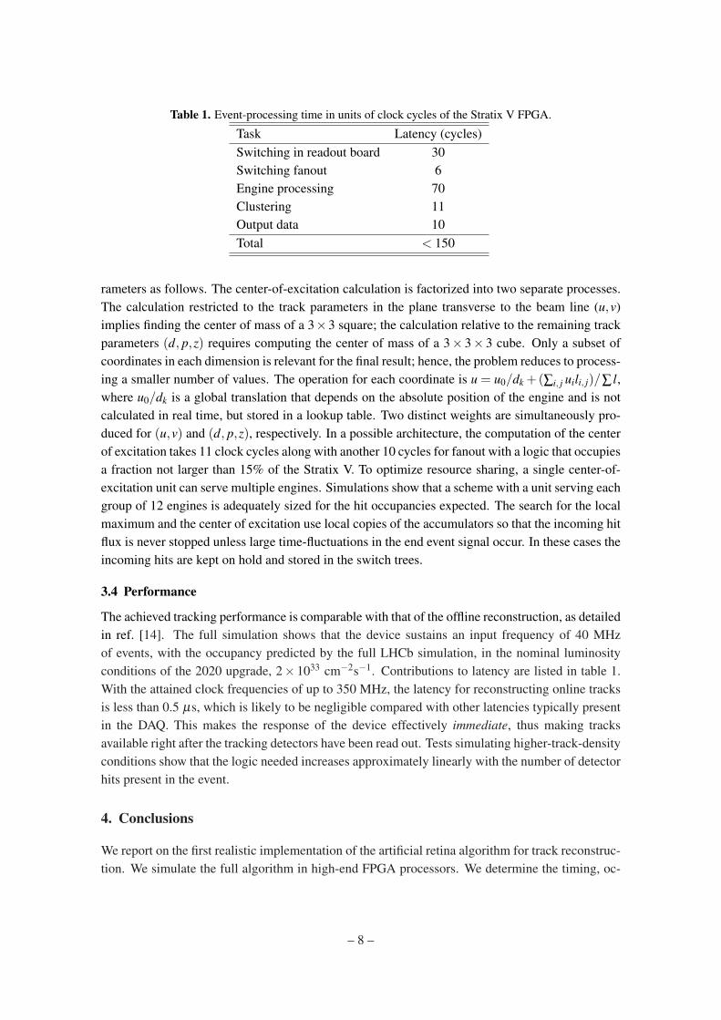
Table 1. Event-processing time in units of clock cycles of the Stratix V FPGA.
Task Latency (cycles)Switching in readout board 30Switching fanout 6Engine processing 70Clustering 11Output data 10Total < 150
rameters as follows. The center-of-excitation calculation is factorized into two separate processes.The calculation restricted to the track parameters in the plane transverse to the beam line (u,v)implies finding the center of mass of a 3×3 square; the calculation relative to the remaining trackparameters (d, p,z) requires computing the center of mass of a 3× 3× 3 cube. Only a subset ofcoordinates in each dimension is relevant for the final result; hence, the problem reduces to process-ing a smaller number of values. The operation for each coordinate is u = u0/dk +(∑i, j uili, j)/∑ l,where u0/dk is a global translation that depends on the absolute position of the engine and is notcalculated in real time, but stored in a lookup table. Two distinct weights are simultaneously pro-duced for (u,v) and (d, p,z), respectively. In a possible architecture, the computation of the centerof excitation takes 11 clock cycles along with another 10 cycles for fanout with a logic that occupiesa fraction not larger than 15% of the Stratix V. To optimize resource sharing, a single center-of-excitation unit can serve multiple engines. Simulations show that a scheme with a unit serving eachgroup of 12 engines is adequately sized for the hit occupancies expected. The search for the localmaximum and the center of excitation use local copies of the accumulators so that the incoming hitflux is never stopped unless large time-fluctuations in the end event signal occur. In these cases theincoming hits are kept on hold and stored in the switch trees.
3.4 Performance
The achieved tracking performance is comparable with that of the offline reconstruction, as detailedin ref. [14]. The full simulation shows that the device sustains an input frequency of 40 MHzof events, with the occupancy predicted by the full LHCb simulation, in the nominal luminosityconditions of the 2020 upgrade, 2× 1033 cm−2s−1. Contributions to latency are listed in table 1.With the attained clock frequencies of up to 350 MHz, the latency for reconstructing online tracksis less than 0.5 µs, which is likely to be negligible compared with other latencies typically presentin the DAQ. This makes the response of the device effectively immediate, thus making tracksavailable right after the tracking detectors have been read out. Tests simulating higher-track-densityconditions show that the logic needed increases approximately linearly with the number of detectorhits present in the event.
4. Conclusions
We report on the first realistic implementation of the artificial retina algorithm for track reconstruc-tion. We simulate the full algorithm in high-end FPGA processors. We determine the timing, oc-
– 8 –
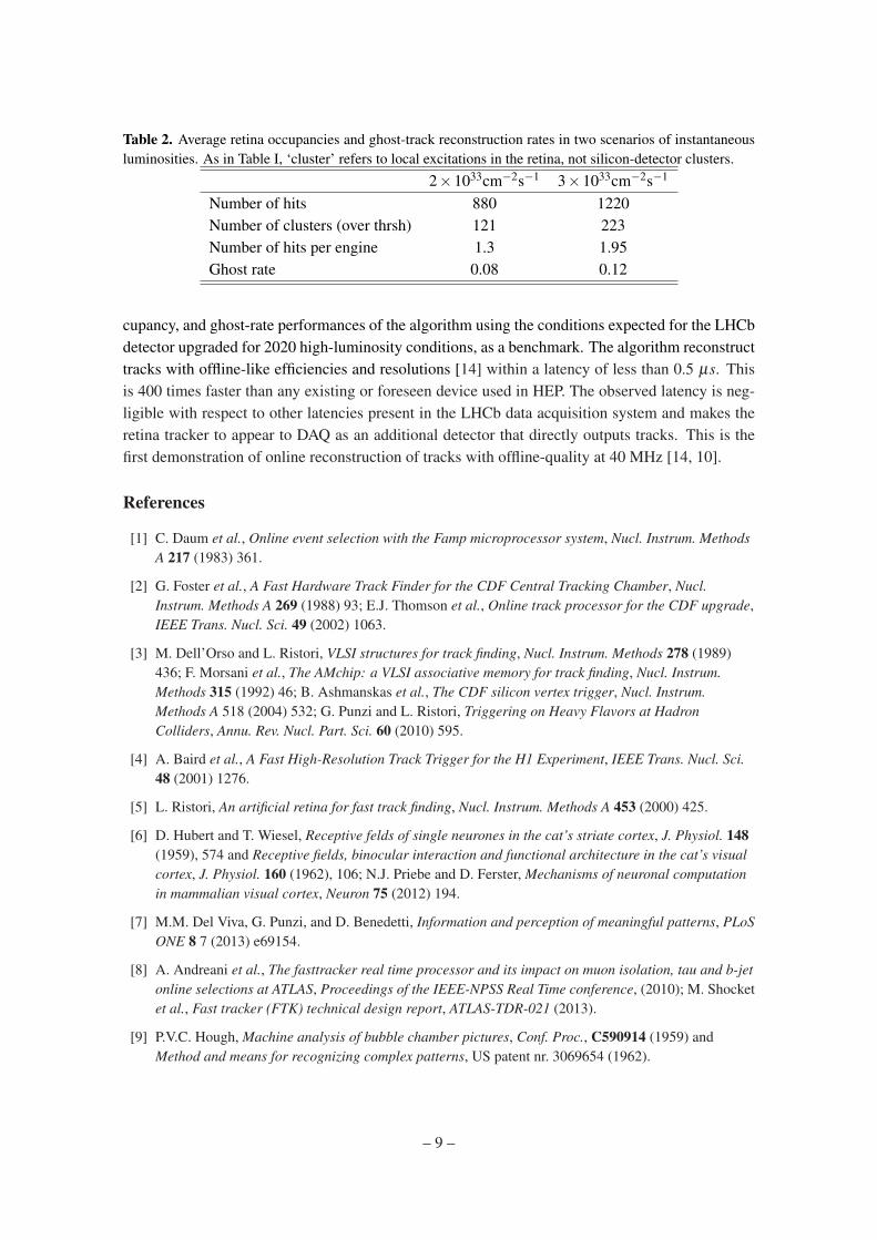
Table 2. Average retina occupancies and ghost-track reconstruction rates in two scenarios of instantaneousluminosities. As in Table I, ‘cluster’ refers to local excitations in the retina, not silicon-detector clusters.
2×1033cm−2s−1 3×1033cm−2s−1
Number of hits 880 1220Number of clusters (over thrsh) 121 223Number of hits per engine 1.3 1.95Ghost rate 0.08 0.12
cupancy, and ghost-rate performances of the algorithm using the conditions expected for the LHCbdetector upgraded for 2020 high-luminosity conditions, as a benchmark. The algorithm reconstructtracks with offline-like efficiencies and resolutions [14] within a latency of less than 0.5 µs. Thisis 400 times faster than any existing or foreseen device used in HEP. The observed latency is neg-ligible with respect to other latencies present in the LHCb data acquisition system and makes theretina tracker to appear to DAQ as an additional detector that directly outputs tracks. This is thefirst demonstration of online reconstruction of tracks with offline-quality at 40 MHz [14, 10].
References
[1] C. Daum et al., Online event selection with the Famp microprocessor system, Nucl. Instrum. MethodsA 217 (1983) 361.
[2] G. Foster et al., A Fast Hardware Track Finder for the CDF Central Tracking Chamber, Nucl.Instrum. Methods A 269 (1988) 93; E.J. Thomson et al., Online track processor for the CDF upgrade,IEEE Trans. Nucl. Sci. 49 (2002) 1063.
[3] M. Dell’Orso and L. Ristori, VLSI structures for track finding, Nucl. Instrum. Methods 278 (1989)436; F. Morsani et al., The AMchip: a VLSI associative memory for track finding, Nucl. Instrum.Methods 315 (1992) 46; B. Ashmanskas et al., The CDF silicon vertex trigger, Nucl. Instrum.Methods A 518 (2004) 532; G. Punzi and L. Ristori, Triggering on Heavy Flavors at HadronColliders, Annu. Rev. Nucl. Part. Sci. 60 (2010) 595.
[4] A. Baird et al., A Fast High-Resolution Track Trigger for the H1 Experiment, IEEE Trans. Nucl. Sci.48 (2001) 1276.
[5] L. Ristori, An artificial retina for fast track finding, Nucl. Instrum. Methods A 453 (2000) 425.
[6] D. Hubert and T. Wiesel, Receptive felds of single neurones in the cat’s striate cortex, J. Physiol. 148(1959), 574 and Receptive fields, binocular interaction and functional architecture in the cat’s visualcortex, J. Physiol. 160 (1962), 106; N.J. Priebe and D. Ferster, Mechanisms of neuronal computationin mammalian visual cortex, Neuron 75 (2012) 194.
[7] M.M. Del Viva, G. Punzi, and D. Benedetti, Information and perception of meaningful patterns, PLoSONE 8 7 (2013) e69154.
[8] A. Andreani et al., The fasttracker real time processor and its impact on muon isolation, tau and b-jetonline selections at ATLAS, Proceedings of the IEEE-NPSS Real Time conference, (2010); M. Shocketet al., Fast tracker (FTK) technical design report, ATLAS-TDR-021 (2013).
[9] P.V.C. Hough, Machine analysis of bubble chamber pictures, Conf. Proc., C590914 (1959) andMethod and means for recognizing complex patterns, US patent nr. 3069654 (1962).
– 9 –

[10] A. Abba et al., A specialized track processor for the LHCb upgrade, CERN-LHCb-PUB-2014-026(2014).
[11] LHCb Collaboration Framework TDR for the LHCb Upgrade, CERN-LHCC-2012-007 (2012).
[12] LHCb Collaboration, LHCb VELO Upgrade Technical Design Report, LHCB-TDR-013 (2013).
[13] LHCb Collaboration, LHCb Tracker Upgrade Technical Design Report, LHCB-TDR-015 (2014).
[14] P. Marino et al., Simulation and performance of an artificial retina for 40 MHz track reconstruction,in these proceedings (2014) [hep-ex/1409.0898].
– 10 –