Embed Size (px)
Citation preview

TF-1418
Serial No: 605-12101 to 605-13199
Band Sawing Machine
Part
s M
anua
l

MACHINE SPECIFICATIONS
MODEL SERIAL NO.
PHASECYCLEVOLTAGE
For your information and future reference, insert pertinent data concerning your ma-chine in the spaces provided above. This information is printed on a label attached to the machine frame.
Always specify model and serial numbers on all parts orders and correspondence concerning your machine. This will help avoid unnecessary delays and inconvenience during processing.
The specifications contained herein were in effect at the time this manual was approved for printing. The DoALL Company, whose policy is one of continuous product improve-ment, reserves the right to change specifications or design at any time without notice and without incurring obligations.
How to read your serial number:
YOUR SERVICE REPRESENTATIVE:
For Sales, Parts and Service, call 1-888-362-5572For general information, visit our web site at: www.doallsawing.com
DoALL SAWING PRODUCTS2375B TOUHY AVENUEELK GROVE, ILLINOIS 60007 U.S.A.

PARTS MANUAL INDEX 12/13
Fiche No. D-24 Model TF-1418 Serial No. 605-12101 to 605-13199_ PAGE NO. DESCRIPTION FIRST SERIAL LAST SERIAL PAGES TF-1-78 Final Assembly All 2 - 3 TF-4-197 Accumulator All 24 - 25 TF-2-61 Adjusting Screw Assembly (Saw Guide) All 28 - 29 TF-2-60 Band Brush Assembly All 4 - 5 TF-2-59 Bandwheel Assembly (Lower - With Band Tension) All 6 - 7 TF-2-58 Bandwheel (Upper) All 12 - 13 TF-2-63 Bearing Adjustment Assembly All 8 - 9 TF-3-53 Carriage Assembly All 10 - 11 TF-3-52 Cradle Assembly All 12 - 13 TF-4-205 Door Interlocks All 16 - 17 TF-2-58 Drive Assembly All 14 - 15 TF-4-205 Electrical Assembly All 16 - 17 TF-4-206 Electrical Box Enclosure Assembly All 18 - 19 TF-2-57 Head Assembly All 20 - 21 TF-4-197 Hydraulic Assembly All 26 - 27 TF-4-207 Junction Box Assembly (Head) All 22 - 23 TF-5-128 Mist Lubricator Assembly All 24 - 25 TF-2-58 Motor Base Assembly All 14 - 15 TF-4-197 Pneumatic Assembly All 26 - 27 TF-4-197 Pneumatic Controls All 26 - 27 TF-2-62 Post Assembly All 28 - 29 TF-4-207 Pushbutton Box Assembly All 22 - 23 TF-2-61 Saw Guide Assemblies All 30 - 31 TF-3-51 Vise Assembly 605-12101 to 605-13012 32 - 33 TF-3-61 Vise Assembly (Left Hand) 605-13103 to 605-13199 34 - 35 TF-3-62 *Vise Assembly (Right Hand) 605-13103 to 605-13199 36 - 37 *Denotes Attachments or Optional Equipment.
1

NEW DRG.S.C.L. 1-15-13
REVISIONS
TF - 1 - 78 PRINTED IN U.S.A.
MODEL FIRST MACH. LAST MACH.TF-1418 605-12101 605-13199
FINAL ASSEMBLY
1
2
3
4
5
6
9
8
7
1011141516
19
20
21
22
2324
1213
18
17
2

CODE NO. TF-1-78 ____________ ____________
FINAL ASSEMBLY
INDEX PART DESCRIPTION UNITS PER NO. NO. ASS'Y. Ref. 225040 Final Assembly Ref. 522860 Saw and Base Assembly 1 225214 . Electrical Assembly (See Detail) ............................................................ 1 2 225275 . Pneumatic/Hydraulic Assembly (See Detail) ......................................... 1 3 225274 . Mist Lubricator Assembly (See Detail) ................................................... 1 4 421632 . Cradle Assembly (See Detail) ................................................................ 1 5 1012541 . Label (Machine Data) ............................................................................. 1 6 201469 . Decal (Flag) ........................................................................................... 1 7 1009936 . Label (DoALL Logo) ............................................................................... 1 8 522857 . Head Assembly (See Detail) .................................................................. 1 9 225142 . Saw Band (1", 4-6P, 157" Long) ............................................................ 1 10 225000 . Handle Ratchet (Also Used for Band Tensioning) ................................. 1 11 421627 . Chip Pan Weldment ............................................................................... 1 12 522858 . Carriage Assembly (See Detail) ............................................................ 1 13 1014248 . Counterbalance Weight ......................................................................... 1 14 198303 . Screw, Soc. Hd. Cap 1/2-13NC x 4 ....................................................... 6 15 198076 . Screw, Hex. Hd. Cap 1/2-13NC x 4 ....................................................... 4 16 199327 . Washer, Lock 1/2 Std. ............................................................................ 4 17 201467 . Label (Warning - Eye Protection) ........................................................... 1 18 201465 . Label (Warning - Saw Blade) ................................................................. 1 19 225028 . Magnetic Digital Angle Gauge ............................................................... 1 20 421635 . Vise Assembly (See Detail) ................................................................... 1 21 522854 . Base Weldment ...................................................................................... 1 22 421629 . Chip Pan Wing Weldment ...................................................................... 2 23 1014228 . Front Panel ............................................................................................. 1 24 199243 . Screw, Button Hd. Soc. M5-0.8 x 12 ...................................................... 6 Following Not Shown: 225301 . Documentation CD ................................................................................. 1 1014171 . Shipping Bracket .................................................................................... 1 404476 . Label (Warning) (Rear Drive Cover) ...................................................... 1 1018687 . Saw Band Selector (Rear Drive Cover) ................................................. 1
3

NEW DRG.S.C.L. 1-15-13
REVISIONS
TF - 2 - 60 PRINTED IN U.S.A.
MODEL FIRST MACH. LAST MACH.TF-1418 605-12101 605-13199
BAND BRUSH ASSEMBLY
1 23
4 5 6
7810
1112
9
4

CODE NO. TF-2-60 ____________ ____________
BAND BRUSH ASSEMBLY
INDEX PART DESCRIPTION UNITS PER NO. NO. ASS'Y. Ref. 320800 Band Brush Assembly 1 010983 . Wire Brush ............................................................................................. 2 2 208826 . Retaining Ring ....................................................................................... 1 3 133470 . Spacer (.0149) ....................................................................................... A.R. 4 133471 . Spacer (.0299) ....................................................................................... A.R. 5 320799 . Bracket Weldment .................................................................................. 1 6 209672 . Shaft ....................................................................................................... 1 7 004260 . Spring Pin ............................................................................................... 1 8 320801 . Pinion ..................................................................................................... 1 9 207462 . Bearing ................................................................................................... 2 10 199222 . Nut, Hex. Jam M12-1.75 ........................................................................ 2 Mounting Band Brush: 11 199051 . Screw, Soc. Hd. Cap M6-1.0 x 12 ......................................................... 2 12 199965 . Washer, Flat M6 ..................................................................................... 2
5
NEW DRG.S.C.L. 1-15-13
REVISIONS
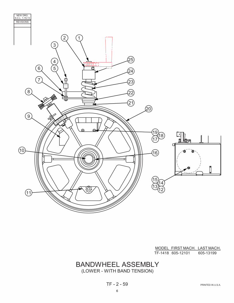
TF - 2 - 59 PRINTED IN U.S.A.
MODEL FIRST MACH. LAST MACH.TF-1418 605-12101 605-13199
BANDWHEEL ASSEMBLY(LOWER - WITH BAND TENSION)
13
456
7
8
9
10
11
16
1719
18
2021
22
23
24
1315
1412
25
2
6
CODE NO. TF-2-59 ____________ ____________
BANDWHEEL ASSEMBLY
(Lower - With Band Tension) INDEX PART DESCRIPTION UNITS PER NO. NO. ASS'Y. Ref. 421633 Bandwheel Assembly (Lower - With Band Tension) 1 224599 . Band Tension Screw .............................................................................. 1 2 1013354 . Collar ...................................................................................................... 1 3 199756 . Screw, Soc. Hd. Cap M6-1.0 x 70 ......................................................... 1 4 1014374 . Close Nipple ........................................................................................... 1 5 202383 . Adhesive (Loctite #242) ......................................................................... A.R. 6 225023 . Actuator .................................................................................................. 1 7 199188 . Nut, Hex. M6-1.0 .................................................................................... 2 8 320800 . Band Brush Assembly (See Detail) ....................................................... 1 9 327203 . Brush Bracket Weldment ....................................................................... 1 10 327202 . Head Slide Sub-Assembly ..................................................................... 1 11 517542 . Head Casting ......................................................................................... 1 12 005956 . Adjustment Screw 3/4-10NC x 2-5/16 (.42 Dia.) ................................... 3 13 100142 . Nut, Hex. Jam 3/4-10NC ........................................................................ 3 14 199980 . Screw, Soc. Hd. Cap M10-1.5 x 80 ....................................................... 3 15 199346 . Washer, Lock M10 ................................................................................. 3 16 204455 . Retaining Ring ....................................................................................... 1 17 199662 . Screw, Soc. Hd. Cap M6-1.0 x 25 ......................................................... 4 18 199965 . Washer, Flat M6 ..................................................................................... 4 19 224583 . Spacer .................................................................................................... 2 20 225001 . Bandwheel Assembly (Idler) .................................................................. 1 522856 . . Bandwheel ........................................................................................... 1 137905 . . Ball Bearing .......................................................................................... 2 21 1014101 . Collar 3/4-10NC (L.H.) ........................................................................... 1 22 108749 . Thrust Ball Bearing ................................................................................ 1 23 108748 . Tube ....................................................................................................... 1 24 108750 . Compression Spring .............................................................................. 1 25 157703 . Rubber Bushing ..................................................................................... 1
7

NEW DRG.S.C.L. 1-15-13
REVISIONS
TF - 2 - 63 PRINTED IN U.S.A.
MODEL FIRST MACH. LAST MACH.TF-1418 605-13104 605-13199
BEARING ADJUSTMENT ASSEMBLY
123456
MODEL FIRST MACH. LAST MACH.TF-1418 605-12101 605-12103
TYPICAL BOTH SIDES
12
3 4 5 6 87 9 10 1211
8

CODE NO. TF-2-63 ____________ ____________
BEARING ADJUSTMENT ASSEMBLY
INDEX PART DESCRIPTION UNITS PER NO. NO. ASS'Y. Ref. 225003 Bearing Adjustment Assembly 1 199819 . Screw, Soc. Hd. Cap M8-1.25 x 16 ....................................................... 4 2 199967 . Washer, Flat M8 ..................................................................................... 4 3 225004 . Adjuster Plate ......................................................................................... 1 4 1008462 . Ball Bearing ............................................................................................ 1 5 199102 . Screw, Soc. Hd. Cap M8-1.25 x 25 (Low Head) .................................... 2 6 199941 . Nut, Hex. M8-1.25 .................................................................................. 2 Ref. 1014186 Bearing Adjustment Assembly 1 198167 . Screw, Hex. Hd. Cap M8-1.25 x 40 ....................................................... 1 2 199250 . Nut, Hex. Jam M8-1.25 .......................................................................... 1 3 199967 . Washer, Flat M8 ..................................................................................... 1 4 199926 . Screw, Hex. Hd. Cap M8-1.25 x 25 ....................................................... 4 5 1014264 . Tie Bar .................................................................................................... 1 6 1014265 . Adjustable Bearing Plate ........................................................................ 1 7 199926 . Screw, Hex. Hd. Cap M8-1.25 x 25 ....................................................... 8 8 199264 . Washer, Flat 3/8 S.A.E. Std. .................................................................. 8 9 1014407 . Flanged Bearing ..................................................................................... 2 10 199102 . Screw, Soc. Hd. Cap M8-1.25 x 25 (Low Head) .................................... 4 11 199941 . Nut, Hex. M8-1.25 .................................................................................. 4 12 199264 . Washer, Flat 3/8 S.A.E. Std. .................................................................. 4
9

NEW DRG.S.C.L. 1-15-13
REVISIONS
TF - 3 - 53 PRINTED IN U.S.A.
MODEL FIRST MACH. LAST MACH.TF-1418 605-12101 605-13199
CARRIAGE ASSEMBLY
1 2 3 54 6 7 98 10 11 12 1513 171614
181920212224 2326 2528 27293031
10

CODE NO. TF-3-53 ____________ ____________
CARRIAGE ASSEMBLY
INDEX PART DESCRIPTION UNITS PER NO. NO. ASS'Y. Ref. 522858 Carriage Assembly 1 199896 . Screw, Soc. Hd. Cap M10-1.5 x 25 ...................................................... 4 2 012596 . Nut, Slotted Hex. 3/4-16NF ................................................................... 1 3 199268 . Washer, Flat 3/4 S.A.E. Std. ................................................................. 3 4 117670 . Handwheel Knob ................................................................................... 1 5 199266 . Washer, Flat 1/2 S.A.E. Std. ................................................................. 1 6 225029 . Rod Clamp ............................................................................................ 2 7 225031 . Angle Clamp Rod .................................................................................. 2 8 225030 . Clamp Nut ............................................................................................. 1 9 004294 . Spring Pin .............................................................................................. 1 10 522867 . Carriage Weldment ............................................................................... 1 11 157703 . Rubber Bushing .................................................................................... 2 12 147519 . Screw, Soc. Hd. Shoulder 5/8-11NC x 1-1/4 (3/4 Dia.) ........................ 2 13 202605 . DU Sleeve Bearing ............................................................................... 2 14 202606 . DU Thrust Washer ................................................................................ 4 15 220181 . Washer, Flat 1-1/4 S.A.E. Std. .............................................................. 2 16 327024 . Linear Bearing Rail and Truck .............................................................. 2 17 199898 . Screw, Soc. Hd. Cap M5-0.8 x 16 ........................................................ 22 18 327206 . Pivot Block ............................................................................................ 2 19 199287 . Screw, Soc. Hd. Cap M10-1.5 x 60 ...................................................... 8 20 199898 . Screw, Soc. Hd. Cap M5-0.8 x 16 ........................................................ 16 21 157703 . Rubber Bushing .................................................................................... 4 22 110980 . Screw, Soc. Hd. Shoulder 5/8-11NC x 2-3/4 (3/4 Dia.) ........................ 2 23 225029 . Rod Clamp ............................................................................................ 2 24 004273 . Spring Pin .............................................................................................. 2 25 176374 . Screw, Soc. Hd. Shoulder 3/8-16NC x 1-1/2 (1/2 Dia.) ........................ 1 26 199280 . Washer, Flat M12 .................................................................................. 1 27 327207 . Cylinder Connector Bracket .................................................................. 1 28 199993 . Screw, Soc. Hd. Cap M6-1.0 x 20 ........................................................ 4 29 199119 . Nut, Hex. 1/4-28NF ............................................................................... 4 30 225006 . Cylinder Mounting Bracket .................................................................... 1 31 1014241 . Air Cylinder (Feed) ................................................................................ 1
11

NEW DRG.S.C.L. 1-15-13
REVISIONS
TF - 3 - 52 PRINTED IN U.S.A.
MODEL FIRST MACH. LAST MACH.TF-1418 605-12101 605-13199
CRADLE ASSEMBLY
2 3
4
12
5
6
78
11
109
1
12

CODE NO. TF-3-52 ____________ ____________
CRADLE ASSEMBLY
INDEX PART DESCRIPTION UNITS PER NO. NO. ASS'Y. Ref. 421632 Cradle Assembly 1 421647 . Cradle End Plate ................................................................................... 1 2 199285 . Washer, Flat M16 .................................................................................. 1 3 199059 . Nut, Hex. M16-2.0 ................................................................................. 1 4 225024 . Pin ......................................................................................................... 1 5 1014413 . Screw, Hex. Hd. Cap M16-2.0 x 150 (Black Oxide) ............................. 1 6 421646 . Cradle Weldment .................................................................................. 1 7 225025 . Pin ......................................................................................................... 1 8 003077 . Retaining Ring ...................................................................................... 2 9 198990 . Screw, Soc. Hd. Cap M12-1.75 x 25 .................................................... 1 10 199445 . Screw, Soc. Set M12-1.75 x 16 (Cone Point) ....................................... 1 11 198990 . Screw, Soc. Hd. Cap M12-1.75 x 25 .................................................... 9 12 225141 . Shim (.06) .............................................................................................. 2
13

NEW DRG.S.C.L. 1-15-13
REVISIONS
TF - 2 - 58 PRINTED IN U.S.A.
MODEL FIRST MACH. LAST MACH.TF-1418 605-12101 605-13199
DRIVE ASSEMBLY
MOTOR BASE ASSEMBLY
123456
79
8
10
11 12 1413 1715 1918 212016
22 23 24
2526
272829303132
12
75
4
3
6
8 9 10 11
33
14

CODE NO. TF-2-58 ____________ ____________
DRIVE ASSEMBLY
INDEX PART DESCRIPTION UNITS PER NO. NO. ASS'Y. Ref. 421625 Drive Assembly 1 225020 . Flanged Bearing ..................................................................................... 2 2 198990 . Screw, Hex. Hd. Soc. M12-1.75 x 25 ..................................................... 4 3 522855 . Bandwheel ............................................................................................. 1 4 224598 . Tapered Bushing .................................................................................... 1 5* 1014287 . Bearing Cover ........................................................................................ 1 6 199819 . Screw, Soc. Hd. Cap M8-1.25 x 16 ....................................................... 2 7 224595 . Shaft ....................................................................................................... 1 8 004443 . Key ......................................................................................................... 2 9 35-007558 . Retaining Ring (Far Side) ...................................................................... 1 10* 1014286 . Bearing Adjustment Assembly (See Detail) ........................................... 2 11 327205 . Motor Base Assembly (See Detail) ........................................................ 1 12 172762 . Door Latch .............................................................................................. 1 13 225017 . Latch Bracket ......................................................................................... 1 14 199246 . Screw, Soc. Hd. Cap M6-1.0 x 12 ......................................................... 2 15 224596 . Shaft ....................................................................................................... 1 16 014215 . Key ......................................................................................................... 2 17 003077 . Retaining Ring (Far Side) ...................................................................... 1 18 327209 . Front Plate .............................................................................................. 1 19 199929 . Screw, Soc. Hd. Soc. M12-1.75 x 20 ..................................................... 6 20 421637 . Upper Door Weldment ........................................................................... 1 21 199246 . Screw, Soc. Hd. Cap M6-1.0 x 12 ......................................................... 3 22 1014156 . Rear Drive Cover Weldment .................................................................. 1 23 199246 . Screw, Soc. Hd. Cap M6-1.0 x 12 ......................................................... 5 24 199819 . Screw, Soc. Hd. Cap M8-1.25 x 16 ....................................................... 4 25 209621 . Electric Motor ......................................................................................... 1 209622 . Electric Motor (575V Only) ..................................................................... 1 26 224597 . Motor Sheave ......................................................................................... 1 27 225096 . V-Belt ..................................................................................................... 1 28 1014249 . Timing Pulley .......................................................................................... 1 29 1014250 . Taperlock Bushing ................................................................................. 1 30 225095 . Sheave ................................................................................................... 1 31 1014252 . Timing Belt ............................................................................................. 1 32 1014251 . Timing Pulley .......................................................................................... 1 33 1014254 . Taperlock Bushing ................................................................................. 1 *NOTE: Before Serial #605-13104: 5 225098 . Bearing Cover ........................................................................................ 1 10 225003 . Bearing Adjustment Assembly (See Detail) ........................................... 2 Ref. 327205 . Motor Base Assembly 1 199836 . Screw, Hex. Hd. Cap M8-1.25 x 16 ....................................................... 4 2 199968 . Washer, Lock M8 ................................................................................... 4 3 225011 . Hinged Base Plate Weldment ................................................................ 1 4 225010 . Motor Base Plate Weldment .................................................................. 1 5 225012 . Pin ......................................................................................................... 1 6 199266 . Washer, Flat 1/2 S.A.E. Std. .................................................................. 2 7 35-008688 . Retaining Ring ....................................................................................... 2 8 199836 . Screw, Hex. Hd. Cap M8-1.25 x 16 ....................................................... 4 9 199968 . Washer, Lock M8 ................................................................................... 4 10 199222 . Nut, Hex. Jam M12-1.75 ........................................................................ 1 11 199845 . Screw, Hex. Hd. Soc. M12-1.75 x 50 ..................................................... 1
15

NEW DRG.S.C.L. 1-15-13
REVISIONS
TF - 4 - 205 PRINTED IN U.S.A.
MODEL FIRST MACH. LAST MACH.TF-1418 605-12101 605-13199
ELECTRICAL ASSEMBLY
1
23
45
78910 61112
1314
1517
1819
16
20
2122
2423
252731 29262830
3335
3634
394038
37
41 42 4543
32
44
4647
48
49
50
51
52 54 56 57 58 5953 55
60 62 64 65 6761 63 66
16

CODE NO. TF-4-205 ____________ ____________
ELECTRICAL ASSEMBLY INDEX PART DESCRIPTION UNITS PER NO. NO. ASS'Y. Ref. 225214 Electrical Assembly 1 . Pushbutton Box Assembly (See Detail) ............................................................................. 1 2 215624 . Limit Switch (Door Interlock) .............................................................................................. 1 3 199389 . Screw, Button Hd. Soc. M4-0.7 x 30 .................................................................................. 2 4 225135 . Switch Key Bracket ............................................................................................................ 1 5 199728 . Screw, Button Hd. Soc. M4-0.7 x 30 .................................................................................. 4 6 215619 . Cord Grip Connector (.236-.472) ........................................................................................ 1 7 167329 . Hose Clamp ........................................................................................................................ 1 8 199974 . Screw, Button Hd. Soc. M5-0.8 x 10 .................................................................................. 1 9 201688 . Cord Grip Connector (.200-.394) ........................................................................................ 1 10 197332 . Electrical Cord (#18-2 Conductor) ...................................................................................... A.R. 11 201688 . Cord Grip Connector (.200-.394) ........................................................................................ 1 12 197332 . Electrical Cord (#18-2 Conductor) ...................................................................................... A.R. 13 201696 . Cord Grip Connector (.394-.551) ........................................................................................ 1 14 197436 . Electrical Cord (#18-8 Conductor) ...................................................................................... A.R. 15 . Junction Box Assembly (Head) (See Detail) ...................................................................... 1 16 199969 . Screw, Button Hd. Soc. M6-1.0 x 10 .................................................................................. 4 17 176528 . Label (Electrical Hazard) .................................................................................................... 1 18 015835 . Cord Grip Connector (.500-.625) ........................................................................................ 1 19 197218 . Electrical Cord (#14-4 Conductor) ...................................................................................... A.R. 20 197351 . Grommet Strip .................................................................................................................... A.R. 21 201687 . Cord Grip Connector (.545-.709) ........................................................................................ 1 22 197218 . Electrical Cord (#14-4 Conductor) ...................................................................................... A.R. 23 201696 . Cord Grip Connector (.394-.551) ........................................................................................ 1 24 197436 . Electrical Cord (#18-8 Conductor) ...................................................................................... A.R. 25 014486 . Sealtite Connector .............................................................................................................. 1 26 014480 . Flange Washer ................................................................................................................... 1 27 014772 . Insulated Bushing ............................................................................................................... 1 28 197158 . Sealtite Conduit 3/4 I.D. ..................................................................................................... A.R. 29 199202 . Nut, Hex. M5-0.8 ................................................................................................................ 4 30 199244 . Washer, Flat M5. ................................................................................................................ 4 31 199348 . Washer, Lock M5 ............................................................................................................... 4 32 1014111 . Console Column ................................................................................................................. 1 33 199981 . Screw, Soc. Hd. Cap M8-1.25 x 30 .................................................................................... 4 34 199941 . Nut, Hex. M8-1.25 .............................................................................................................. 4 35 1014174 . Column Cover .................................................................................................................... 1 36 199527 . Screw, Pan Hd. Self-Tap M5.5 x 13 ................................................................................... 4 37 014484 . 90° Sealtite Connector ....................................................................................................... 1 38 014480 . Flange Washer ................................................................................................................... 1 39 015607 . Bond Nut ............................................................................................................................ 1 40 197158 . Sealtite Conduit 3/4 I.D. ..................................................................................................... A.R. 41 201687 . Cord Grip Connector (.545-.709) ........................................................................................ 1 42 1004154 . 3-Hole Insert ....................................................................................................................... 1 43 199896 . Screw, Soc. Hd. Cap M10-1.5 x 25 .................................................................................... 2 44 199939 . Nut, Hex. M10-1.5 .............................................................................................................. 2 45 199346 . Washer, Lock M10 ............................................................................................................. 2 46 199919 . Screw, Soc. Hd. Cap M10-1.5 x 25 .................................................................................... 2 47 199346 . Washer, Lock M10 ............................................................................................................. 2 48 . Electrical Box Enclosure Assembly (See Detail) ................................................................ 1 49 201464 . Label (Danger - High Voltage) ............................................................................................ 1 50 176528 . Label (Electrical Hazard) .................................................................................................... 1 51 224950 . Solenoid DIN Connector (Mist Lube) .................................................................................. 1 52 1014169 . Spacer ................................................................................................................................ 2 53 1014175 . Enclosure Mounting Bracket .............................................................................................. 1 54 199818 . Screw, Soc. Hd. Cap M10-1.5 x 20 .................................................................................... 2 55 199346 . Washer, Lock M10 ............................................................................................................. 2 56 198976 . Washer, Flat M10 ............................................................................................................... 2 57 197332 . Electrical Cord (#18-2 Conductor) ...................................................................................... A.R. 58 167329 . Hose Clamp ........................................................................................................................ 4 59 199974 . Screw, Button Hd. Soc. M5-0.8 x 10 .................................................................................. 4 60 215624 . Limit Switch (Door Interlock) .............................................................................................. 1 61 199389 . Screw, Button Hd. Soc. M4-0.7 x 30 .................................................................................. 2 62 225135 . Switch Key Bracket ............................................................................................................ 1 63 199728 . Screw, Button Hd. Soc. M4-0.7 x 30 .................................................................................. 4 64 215619 . Cord Grip Connector (.236-.472) ........................................................................................ 1 65 1014114 . Column Bracket Weldment ................................................................................................. 1 66 199818 . Screw, Soc. Hd. Cap M10-1.5 x 20 .................................................................................... 2 67 199346 . Washer, Lock M10 ............................................................................................................. 2
17

NEW DRG.S.C.L. 1-15-13
REVISIONS
TF - 4 - 206 PRINTED IN U.S.A.
MODEL FIRST MACH. LAST MACH.TF-1418 605-12101 605-13199
ELECTRICAL BOX ENCLOSURE ASSEMBLY
Enclosure Door Removed to Show Detail.
12
3
45
76
8
910
1112
1314
1516
1718
19
20
21
22
23
2425
2627
S.C.L. 2-15-13
18

CODE NO. TF-4-206 ____________ ____________
ELECTRICAL BOX ENCLOSURE ASSEMBLY INDEX PART DESCRIPTION UNITS PER NO. NO. ASS'Y. Ref. 225214 Electrical Box Enclosure Assembly 1 1007434 . Disconnect Switch .................................................................................. 1 2 1007437 . Disconnect Switch Handle ..................................................................... 1 3 1007441 . Disconnect Switch Shaft ........................................................................ 1 4 320740 . Grounding Bus ....................................................................................... 1 5 139194 . Wire Terminal Lug .................................................................................. 1 6 197208 . 1” Panel Channel .................................................................................... A.R. 7 197210 . 1” Panel Channel Cover ......................................................................... A.R. 8 222284 . Terminal Block (Yellow) ......................................................................... 2 9 169674 . Mounting Channel .................................................................................. A.R. 10 200618 . End Stop ................................................................................................. 2 11 200615 . Terminal Block (Gray) ............................................................................ 12 12 200617 . End Section ............................................................................................ 3 13 202922 . Jumper Bar ............................................................................................. 1 14 225210 . Terminal Marker Set .............................................................................. 1 15 225213 . Enclosure ............................................................................................... 1 16 225209 . CB and MSP Schedule (Inside Door) ..................................................... 1 17 199126 . Nut, Hex. 3/8-16NC ................................................................................ 4 18 199325 . Washer, Lock 3/8 Std. ............................................................................ 4 19 320113 . Transformer (208V) ................................................................................ 1 320114 . Transformer (230V, 460V, 575V) ........................................................... 1 217753 . Transformer (400V) ................................................................................ 1 20 225206 . Variable Speed Drive Module (208V, 230V) .......................................... 1 225207 . Variable Speed Drive Module (400V, 460V) .......................................... 1 225208 . Variable Speed Drive Module (575V) ..................................................... 1 21 221997 . Control Relay .......................................................................................... 1 22 420361 . Circuit Breaker ....................................................................................... 1 23 1007400 . Circuit Breaker (208V, 230V) ................................................................. 1 1007399 . Circuit Breaker (400V, 460V) ................................................................. 1 215212 . Fuse Block (575V) .................................................................................. 2 203158 . Fuse (1 Amp) (575V) .............................................................................. 2 24 169674 . Mounting Channel .................................................................................. A.R. 27 200618 . End Stop ................................................................................................. 4 26 220647 . Motor Starter Protector (208V, 230V) .................................................... 1 220646 . Motor Starter Protector (400V, 460V) .................................................... 1 220645 . Motor Starter Protector (575V) ............................................................... 1 27 220654 . Auxiliary Contact (1-NO) ........................................................................ 1 Following Not Shown: 1012541 . Label (Machine Data) ............................................................................. 1 197339 . Wire, #14 Black (19 Strand) .................................................................... A.R. 197195 . Wire, #14 Green/Yellow (19 Strand) ...................................................... A.R. 197343 . Wire, #16 Green/Yellow (19 Strand) ...................................................... A.R. 197325 . Wire, #16 White (19 Strand) .................................................................. A.R. 197197 . Wire, #16 Red (19 Strand) ..................................................................... A.R. 197345 . Shielded Cable (#20-3 Conductor) ......................................................... A.R. 007635 . Wire Terminal Ring #10 ......................................................................... 9 207111 . Wire Terminal Locking Fork #8 .............................................................. 5
19

NEW DRG.S.C.L. 1-15-13
REVISIONS
TF - 2 - 57 PRINTED IN U.S.A.
MODEL FIRST MACH. LAST MACH.TF-1418 605-12101 605-13199
HEAD ASSEMBLY
1
2
34
5 6 7 8 9 10 11
12131516 1417
20

CODE NO. TF-2-57 ____________ ____________
HEAD ASSEMBLY
INDEX PART DESCRIPTION UNITS PER NO. NO. ASS'Y. Ref. 522857 Head Assembly 1 421625 . Drive Assembly (See Detail) .................................................................. 1 2 522861 . Head Weldment ..................................................................................... 1 3 421640 . Band Guard Weldment .......................................................................... 1 4 199819 . Screw, Soc. Hd. Cap M8-1.25 x 16 ....................................................... 6 5 522859 . Saw Guide Assemblies (See Detail) ...................................................... 1 6 1014162 . Left Rear Post Guard ............................................................................. 1 7 198373 . Screw, Button Hd. Soc. 5/16-18NC x 3/8 .............................................. 2 8 1014161 . Right Rear Post Guard ........................................................................... 1 9 198025 . Screw, Hex. Hd. Cap 5/16-18NC x 1/2 .................................................. 2 10 1014168 . Handle Weldment .................................................................................. 1 11 199898 . Screw, Soc. Hd. Cap M5-0.8 x 16 ......................................................... 8 12 171912 . Pull Handle ............................................................................................. 1 13 199819 . Screw, Soc. Hd. Cap M8-1.25 x 16 ....................................................... 2 14 172762 . Door Latch .............................................................................................. 1 15 421639 . Lower Door Weldment ........................................................................... 1 16 199246 . Screw, Button Hd. Soc. M6-1.0 x 12 ...................................................... 5 17 421633 . Bandwheel Assembly (Lower - With Band Tension) (See Detail) ......... 1
21
NEW DRG.S.C.L. 1-15-13
REVISIONS
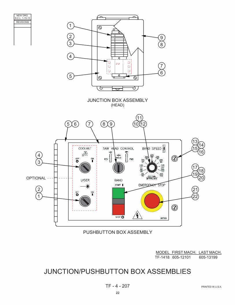
TF - 4 - 207 PRINTED IN U.S.A.
MODEL FIRST MACH. LAST MACH.TF-1418 605-12101 605-13199
JUNCTION/PUSHBUTTON BOX ASSEMBLIES
JUNCTION BOX ASSEMBLY(HEAD)
PUSHBUTTON BOX ASSEMBLY
OPTIONAL
1
23
4
567
89
12
34
5 6 7 98 1011
12
1315
1416
1719
1820
2221
22

CODE NO. TF-4-207 ____________ ____________
JUNCTION/PUSHBUTTON BOX ASSEMBLIES INDEX PART DESCRIPTION UNITS PER NO. NO. ASS'Y. Ref. 225214 Junction Box Assembly (Head) 1 222284 . Terminal Block (Yellow) ......................................................................... 1 2 200615 . Terminal Block (Gray) ............................................................................ 8 3 200617 . End Section ............................................................................................ 3 4 219373 . Power Supply (Laser Option) ................................................................. 1 5 135454 . Junction Box Panel ................................................................................ 1 6 169674 . Mounting Channel .................................................................................. A.R. 7 200618 . End Stop ................................................................................................ 3 8 133882 . Junction Box (With Lift-Off Cover) ......................................................... 1 9 215267 . Gasket Strip ........................................................................................... A.R. Ref. 225214 Pushbutton Box Assembly 1 135106 . Hole Seal (Standard) ............................................................................ 1 207181 . Selector Switch (2 Position) (Laser Option)........................................... 1 2 207185 . Contact Block (1-NO) (Laser Option) .................................................... 1 3 135106 . Hole Seal (Standard) ............................................................................ 1 207181 . Selector Switch (2 Position) (Flood Coolant Option) ............................. 1 4 207185 . Contact Block (1-NO) (Flood Coolant Option) ...................................... 1 5 1014086 . Enclosure Weldment ............................................................................. 1 6 215267 . Gasket Strip .......................................................................................... A.R. 7 327303 . Escutcheon ........................................................................................... 1 8 207181 . Selector Switch (3 Position) .................................................................. 1 9 207185 . Contact Block (1-NO) ............................................................................ 1 10 223353 . Potentiometer ........................................................................................ 1 11 178146 . Knob ...................................................................................................... 1 12 200044 . Hex. Seal ............................................................................................... 1 13 207171 . Rivet Nut M5-0.8 ................................................................................... 2 14 207170 . Screw, Hex. Hd. Slotted M5-0.8 x 20 .................................................... 2 15 204150 . Retaining Ring ...................................................................................... 2 16 204152 . Nylon Washer ....................................................................................... 2 17 221140 . Double Pushbutton Operator (Red/Green) ........................................... 1 18 207185 . Contact Block (1-NO) ............................................................................ 2 19 207186 . Contact Block (1-NC) ............................................................................ 1 20 221385 . Seal Boot ............................................................................................... 1 21 207191 . Pushbutton Operator (Red Mushroom) ................................................ 1 22 207186 . Contact Block (1-NC) ............................................................................ 1
23

NEW DRG.S.C.L. 1-15-13
REVISIONS
TF - 5 - 128 PRINTED IN U.S.A.
MODEL FIRST MACH. LAST MACH.TF-1418 605-12101 605-13199
MIST LUBRICATOR ASSEMBLY
1
2
3
4
5
67
8 9 10 11 12 13
141516171819
24

CODE NO. TF-5-128 ____________ ____________
MIST LUBRICATOR ASSEMBLY
INDEX PART DESCRIPTION UNITS PER NO. NO. ASS'Y. Ref. 225274 Mist Lubricator Assembly 1 199974 . Screw, Button Hd. Soc. M5-0.8 x 10 ...................................................... 4 2 200135 . 90° Swivel Male Elbow ........................................................................... 1 3 323615 . Nozzle Mounting Bracket ....................................................................... 1 4 1014414 . Studded Knob ........................................................................................ 2 5 197142 . Nylon Tubing 1/8 O.D. ........................................................................... A.R. 6 209458 . Hose Clip ................................................................................................ 3 7 199974 . Screw, Button Hd. Soc. M5-0.8 x 10 ...................................................... 3 8 324191 . Mounting Bracket ................................................................................... 1 9 199923 . Screw, Soc. Hd. Cap M6-1.0 x 10 ......................................................... 2 10 260426 . Reducer Bushing ................................................................................... 1 11 5-027506 . 90° Street Elbow .................................................................................... 1 12 176811 . Vent Filter/Breather ................................................................................ 1 13 200135 . 90° Swivel Male Elbow ........................................................................... 1 14 197438 . Polythelene Tubing 1/4 O.D. (Blue) ....................................................... A.R. 15 203144 . Pipe Nipple (Brass) ................................................................................ 1 16 260426 . Reducer Bushing ................................................................................... 1 17 200133 . Swivel Male Elbow ................................................................................. 1 18 208833 . Mist Lubricator (Includes Solenoid, Nozzle, Hose, etc.) ........................ 1 19 199824 . Screw, Soc. Hd. Cap M6-1.0 x 55 ......................................................... 2
25

NEW DRG.S.C.L. 1-15-13
REVISIONS
TF - 4 - 197 PRINTED IN U.S.A.
MODEL FIRST MACH. LAST MACH.TF-1418 605-12101 605-13199
PNEUMATIC/HYDRAULIC ASSEMBLY
28 29 30 31 32
343536383940 37
27
{
{
{{
1
2
3
4
5678910
11
12
1314
15
17 18 19 20 21 22 23 24
414243444546
16 25 26
ORIENTATIONMAYVARY.
26
CODE NO. TF-4-197 ____________ ____________
PNEUMATIC/HYDRAULIC ASSEMBLY
INDEX PART DESCRIPTION UNITS PER NO. NO. ASS'Y. Ref. 517262 Pneumatic/Hydraulic Assembly 1 200137 . Gauge .................................................................................................... 1 2 206114 . Air Regulator .......................................................................................... 1 3 327304 . Escutcheon ............................................................................................ 1 4 158827 . Needle Valve .......................................................................................... 1 5 133542 . Service Tee ............................................................................................ 1 6 134352 . Reducer Bushing ................................................................................... 1 7 134352 . Reducer Bushing ................................................................................... 1 8 200135 . 90° Swivel Male Elbow ........................................................................... 1 9 114433 . Manifold .................................................................................................. 1 10 199233 . Screw, Soc. Hd. Cap M6-1.0 x 30 ......................................................... 2 11 5-027506 . 90° Street Elbow .................................................................................... 1 12 200135 . 90° Swivel Male Elbow ........................................................................... 2 13 260426 . Reducer Bushing ................................................................................... 2 14 200135 . 90° Swivel Male Elbow ........................................................................... 2 15 197438 . Polyethylene Tubing 1/4 O.D. (Blue) ..................................................... A.R. 16 176879 . Escutcheon (Air Supply Limits) .............................................................. 1 17 016561 . Hose Clamp ........................................................................................... 3 18 199243 . Screw, Button Hd. Soc. M5-0.8 x 12 ...................................................... 3 19 112043 . Street Tee .............................................................................................. 1 20 260426 . Reducer Bushing ................................................................................... 2 21 203144 . Pipe Nipple (Brass) ................................................................................ 2 22 176811 . Vent Filter Breather ................................................................................ 2 23 176829 . Solenoid Valve ....................................................................................... 2 24 200133 . Male Swivel Connector .......................................................................... 2 25 318130 . Pneumatic Cylinder (Accumulator) ........................................................ 1 26 201030 . Transmission Fluid (1 Quart) ................................................................. A.R. 27 200133 . Male Swivel Connector .......................................................................... 1 28 260426 . Reducer Bushing ................................................................................... 2 29 199819 . Screw, Soc. Hd. Cap M8-1.25 x 16 ....................................................... 4 30 200135 . 90° Swivel Male Elbow ........................................................................... 1 31 158827 . Needle Valve .......................................................................................... 1 32 123835 . 90° Reducing Elbow ............................................................................... 1 34 120857 . Service Tee ............................................................................................ 1 35 008254 . 90° Street Elbow .................................................................................... 1 36 008048 . Check Valve ........................................................................................... 2 37 14-003507 . Close Nipple ........................................................................................... 3 38 260426 . Reducer Bushing ................................................................................... 2 39 200133 . Male Swivel Connector .......................................................................... 2 40 120857 . Service Tee ............................................................................................ 1 41 200133 . Male Swivel Connector .......................................................................... 1 42 260426 . Reducer Bushing ................................................................................... 1 43 120857 . Service Tee ............................................................................................ 1 44 200133 . Male Swivel Connector .......................................................................... 1 45 199040 . Screw, Soc. Hd. Cap M4-0.7 x 35 ......................................................... 2 46 209272 . Filter/Regulator/Lubricator ..................................................................... 1
27

NEW DRG.S.C.L. 1-15-13
REVISIONS
TF - 2 - 62 PRINTED IN U.S.A.
MODEL FIRST MACH. LAST MACH.TF-1418 605-12101 605-13199
POST ASSEMBLY
12
3
4
5
6
7
8
9
28

CODE NO. TF-2-62 ____________ ____________
POST ASSEMBLY
INDEX PART DESCRIPTION UNITS PER NO. NO. ASS'Y. Ref. 224593 Post Assembly 1 198280 . Screw, Soc. Hd. Cap 3/8-16NC x 1-1/4 ................................................ 4 2 199325 . Washer, Lock 3/8 Std. ........................................................................... 4 3 319741 . Post Slide Plate ..................................................................................... 1 4 004282 . Spring Pin .............................................................................................. 2 5 417394 . Post Slide Casting ................................................................................. 1 6 204850 . Spring Plunger ...................................................................................... 2 7 224594 . Knob ...................................................................................................... 1 8 198459 . Screw, Soc. Set 3/8-24NF x 1 ............................................................... 4 9 417400 . Post ....................................................................................................... 1
29

NEW DRG.S.C.L. 1-15-13
REVISIONS
TF - 2 - 61 PRINTED IN U.S.A.
MODEL FIRST MACH. LAST MACH.TF-1418 605-12101 605-13199
SAW GUIDE ASSEMBLIES
ADJUSTING SCREW ASSEMBLY
1 2 3 4 5 6
123
45
6
78
9
1011
12
13
1415
1617
1
2
3
4
GUIDE BLOCK ASSEMBLY(Section A - A)
98756
A A
A A
See Detail Below Right
See Detail Above
30

CODE NO. TF-2-61 ____________ ____________
SAW GUIDE ASSEMBLIES
INDEX PART DESCRIPTION UNITS PER NO. NO. ASS'Y. Ref. 522859 Saw Guide Assembly 1 224593 . Post Assembly (See Detail) ................................................................... 1 2 198246 . Screw, Soc. Hd. Cap 1/4-20NC x 1-3/4 ................................................. 2 3 225089 . Upper Saw Guide Bracket ..................................................................... 1 4 199896 . Screw, Soc. Hd. Cap M10-1.5 x 25 ....................................................... 2 5 198976 . Washer, Flat M10 ................................................................................... 2 6 199409 . Screw, Soc. Set M6-1.0 x 20 ................................................................. 2 7 224566 . Guide Block Assembly (See Detail) ....................................................... 1 8 004251 . Spring Pin ............................................................................................... 2 9 224566 . Guide Block Assembly (See Detail) ....................................................... 1 10 198724 . Screw, Soc. Hd. Cap M10-1.5 x 55 ....................................................... 2 11 198976 . Washer, Flat M10 ................................................................................... 2 12 199409 . Screw, Soc. Set M6-1.0 x 20 ................................................................. 2 13 327228 . Lower Post Weldment ............................................................................ 1 14 005956 . Adjustment Screw 3/4-10NC x 2-5/16 (.42 Dia.) ................................... 3 15 100142 . Nut, Hex. Jam 3/4-10NC ........................................................................ 3 16 199980 . Screw, Soc. Hd. Cap M10-1.5 x 80 ....................................................... 3 17 199346 . Washer, Lock M10 ................................................................................. 3 Ref. 224566 . Guide Block Assembly 1 198749 . . Screw, Flat Hd. Mach. #10-24NC x 1/2 ............................................... 1 2 137158 . . Insert Assembly (Fixed) ....................................................................... 1 3 137155 . . Insert Assembly (Adjustable) ............................................................... 1 4 124419 . . Adjusting Screw Assembly (See Detail) .............................................. 1 5 176077 . . Screw, Soc. Hd. Shoulder M8-1.25 x 16 (10 mm Dia.) ........................ 1 6 198976 . . Washer, Flat M10 ................................................................................. 3 7 199346 . . Washer, Lock M10 ............................................................................... 1 8 011529 . . Ball Bearing .......................................................................................... 1 9 225021 . . Guide Housing ..................................................................................... 1 Ref. 124419 . . Adjusting Screw Assembly 1 124033 . . . Plug .................................................................................................... 1 2 004217 . . . Spring Pin ........................................................................................... 1 3 124418 . . . Housing .............................................................................................. 1 4 104632 . . . Belleville Washer ............................................................................... 6 5 199257 . . . Washer, Flat #8 S.A.E. Std. .............................................................. 1 6 124417 . . . Plunger ............................................................................................... 1
31

NEW DRG.S.C.L.11-15-12
REVISIONS
TF - 3 - 51 PRINTED IN U.S.A.
MODEL FIRST MACH. LAST MACH.TF-1418 605-12101 605-13102
VISE ASSEMBLY
Typical for Both Vises
1
2
3
45
6
7 16
17
18
19
2021
22
25 26
2728293033343635
23
12 13 14 1510 1198
24
3132
S.C.L. 1-15-13
32

CODE NO. TF-3-51 ____________ ____________
VISE ASSEMBLY
INDEX PART DESCRIPTION UNITS PER NO. NO. ASS'Y. Ref. 421635 Vise Assembly 1 199905 . Screw, Flat Hd. Soc. M6-1.0 x 16 ......................................................... 30 2 327234 . L.H. Movable Vise Jaw Weldment ........................................................ 1 3 327231 . Wear Plate ............................................................................................ 1 4 327237 . Vise Wear Plate .................................................................................... 1 5 199905 . Screw, Flat Hd. Soc. M6-1.0 x 16 ......................................................... 6 6 327232 . Wear Plate ............................................................................................ 1 7 225099 . Slide Bar ................................................................................................ 2 8 199896 . Screw, Soc. Hd. Cap M10-1.5 x 25 ...................................................... 2 9 327233 . L.H. Fixed Vise Jaw Weldment ............................................................. 1 10 327235 . Vise Wear Plate .................................................................................... 1 11 199905 . Screw, Flat Hd. Soc. M6-1.0 x 16 ......................................................... 5 199987 . Screw, Flat Hd. Soc. M6-1.0 x 10 ......................................................... 1 12 1014122 . Vise Wear Plate .................................................................................... 1 13 199905 . Screw, Flat Hd. Soc. M6-1.0 x 16 ......................................................... 6 14 1014126 . Vise Screw Mounting Block .................................................................. 1 15 199911 . Screw, Soc. Hd. Cap M10-1.5 x 40 ...................................................... 2 16 199896 . Screw, Soc. Hd. Cap M10-1.5 x 25 ...................................................... 2 17 1014125 . R.H. Fixed Vise Jaw Weldment ............................................................ 1 18 225099 . Slide Bar ................................................................................................ 2 19 327232 . Wear Plate ............................................................................................ 1 20 1014121 . Vise Wear Plate .................................................................................... 1 21 199905 . Screw, Flat Hd. Soc. M6-1.0 x 16 ......................................................... 6 22 1014124 . R.H. Movable Vise Jaw Weldment ....................................................... 1 23 327231 . Wear Plate ............................................................................................ 1 24 199905 . Screw, Flat Hd. Soc. M6-1.0 x 16 ......................................................... 30 25 126535 . Bronze Thrust Bearing .......................................................................... 2 26 1013354 . Collar ..................................................................................................... 2 27 199268 . Washer, Flat 3/4 S.A.E. Std. ................................................................. 2 28 005022 . Sleeve Bearing ...................................................................................... 2 29 225101 . T-Nut (Plain) .......................................................................................... 2 30 199896 . Screw, Soc. Hd. Cap M10-1.5 x 25 ...................................................... 4 31 225100 . T-Nut 1-5 Acme Thread (L.H.) .............................................................. 2 32 199896 . Screw, Soc. Hd. Cap M10-1.5 x 25 ...................................................... 4 33 327236 . Vise Screw 1-5 Acme Thread (L.H.) ..................................................... 2 34 199161 . Nut, Slotted Castellated 5/8-18NF ........................................................ 2 35 004248 . Spring Pin .............................................................................................. 2 36 199267 . Washer, Flat 5/8 S.A.E. Std. ................................................................. 4
33

NEW DRG.S.C.L.11-15-12
REVISIONS
TF - 3 - 61 PRINTED IN U.S.A.
MODEL FIRST MACH. LAST MACH.TF-1418 605-13103 605-13199
VISE ASSEMBLY(LEFT HAND)
8
7
65
10 11
1213141518192120
12
1617
9
34
34

CODE NO. TF-3-61 ____________ ____________
VISE ASSEMBLY
(Left Hand) INDEX PART DESCRIPTION UNITS PER NO. NO. ASS'Y. Ref. 421635 Vise Assembly (Left Hand) 1 199896 . Screw, Soc. Hd. Cap M10-1.5 x 25 ...................................................... 2 2 327233 . L.H. Fixed Vise Jaw Weldment ............................................................. 1 3 327235 . Vise Wear Plate .................................................................................... 1 4 199905 . Screw, Flat Hd. Soc. M6-1.0 x 16 ......................................................... 5 199987 . Screw, Flat Hd. Soc. M6-1.0 x 10 ......................................................... 1 5 327237 . Vise Wear Plate .................................................................................... 1 6 199905 . Screw, Flat Hd. Soc. M6-1.0 x 16 ......................................................... 6 7 327234 . L.H. Movable Vise Jaw Weldment ........................................................ 1 8 199905 . Screw, Flat Hd. Soc. M6-1.0 x 16 ......................................................... 32 9 1014246 . Wear Plate ............................................................................................ 2 10 126535 . Bronze Thrust Bearing .......................................................................... 2 11 1013354 . Collar ..................................................................................................... 2 12 199268 . Washer, Flat 3/4 S.A.E. Std. ................................................................. 2 13 005022 . Sleeve Bearing ...................................................................................... 2 14 1014244 . T-Nut (Plain) .......................................................................................... 2 15 199896 . Screw, Soc. Hd. Cap M10-1.5 x 25 ...................................................... 4 16 1014243 . T-Nut (With 1-5 Acme Thread L.H.) ...................................................... 2 17 199896 . Screw, Soc. Hd. Cap M10-1.5 x 25 ...................................................... 4 18 327236 . Vise Screw (1-5 Acme Thread L.H.) ..................................................... 2 19 199161 . Nut, Slotted Castellated 5/8-18NF ........................................................ 2 20 004248 . Spring Pin .............................................................................................. 2 21 199267 . Washer, Flat 5/8 S.A.E. Std. ................................................................. 4
35
NEW DRG.S.C.L. 1-15-13
REVISIONS
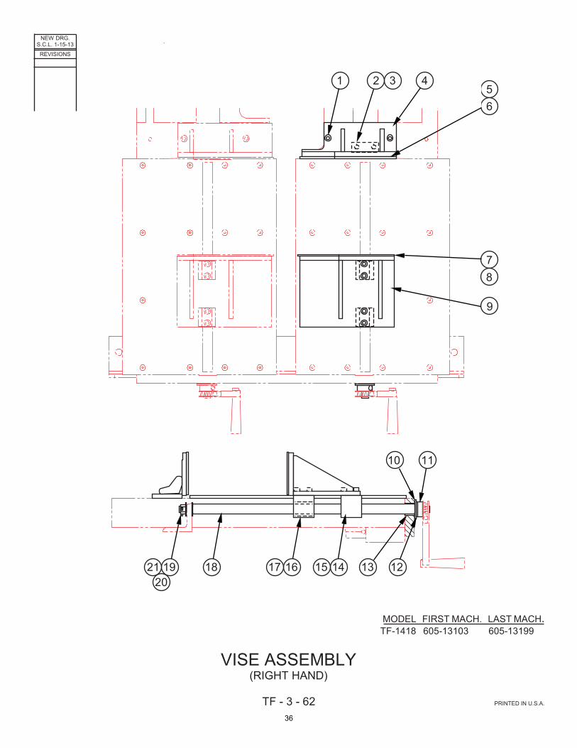
TF - 3 - 62 PRINTED IN U.S.A.
MODEL FIRST MACH. LAST MACH.TF-1418 605-13103 605-13199
VISE ASSEMBLY(RIGHT HAND)
10 11
1213141518192120
1617
1 2 3 456
78
9
36

CODE NO. TF-3-62 ____________ ____________
VISE ASSEMBLY
(Right Hand) INDEX PART DESCRIPTION UNITS PER NO. NO. ASS'Y. Ref. 225303 Vise Assembly (Left Hand) 1 199896 . Screw, Soc. Hd. Cap M10-1.5 x 25 ...................................................... 2 2 1014126 . Vise Screw Mounting Block .................................................................. 1 3 199911 . Screw, Soc. Hd. Cap M10-1.5 x 40 ...................................................... 2 4 1014125 . R.H. Fixed Vise Jaw Weldment ............................................................ 1 5 1014122 . Vise Wear Plate (If Supplied) ................................................................ 1 6 199905 . Screw, Flat Hd. Soc. M6-1.0 x 16 ......................................................... 6 7 1014121 . Vise Wear Plate (If Supplied) ................................................................ 1 8 199905 . Screw, Flat Hd. Soc. M6-1.0 x 16 ......................................................... 6 9 1014124 . R.H. Movable Vise Jaw Weldment ....................................................... 1 10 126535 . Bronze Thrust Bearing .......................................................................... 2 11 1013354 . Collar ..................................................................................................... 2 12 199268 . Washer, Flat 3/4 S.A.E. Std. ................................................................. 2 13 005022 . Sleeve Bearing ...................................................................................... 2 14 1014244 . T-Nut (Plain) .......................................................................................... 2 15 199896 . Screw, Soc. Hd. Cap M10-1.5 x 25 ...................................................... 4 16 1014243 . T-Nut (With 1-5 Acme Thread L.H.) ...................................................... 2 17 199896 . Screw, Soc. Hd. Cap M10-1.5 x 25 ...................................................... 4 18 327236 . Vise Screw (1-5 Acme Thread L.H.) ..................................................... 2 19 199161 . Nut, Slotted Castellated 5/8-18NF ........................................................ 2 20 004248 . Spring Pin .............................................................................................. 2 21 199267 . Washer, Flat 5/8 S.A.E. Std. ................................................................. 4
37
![€¦ · Translate this page%PDF-1.5 %âãÏÓ 1418 0 obj endobj 1438 0 obj /Filter/FlateDecode/ID[]/Index[1418](https://img.pdfslide.us/doc/110x75/5af17cdb7f8b9ac62b90130b/translate-this-pagepdf-15-1418-0-obj-endobj-1438-0-obj-filterflatedecodeid04754e6d382cdc4cbfb605dbce7bd2cb67e0033d9d89c24b80a2f70a8f198973index1418.jpg)