Embed Size (px)
Citation preview

Tetra4D Enrich 2017 SP2 Users Guide – V2.2 1
Tetra4D Enrich
Version 2017 SP2 User Guide Document version: V2.2
Tetra4D Enrich 2017 SP2 Users Guide – V2.2 2
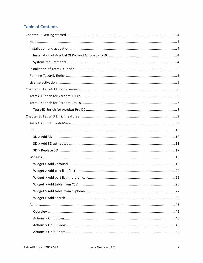
Table of Contents
Chapter 1: Getting started.................................................................................................................... 4
Help .................................................................................................................................................. 4
Installation and activation ................................................................................................................ 4
Installation of Acrobat XI Pro and Acrobat Pro DC ....................................................................... 4
System Requirements ................................................................................................................... 4
Installation of Tetra4D Enrich ........................................................................................................... 5
Running Tetra4D Enrich .................................................................................................................... 5
License activation ............................................................................................................................. 5
Chapter 2: Tetra4D Enrich overview..................................................................................................... 6
Tetra4D Enrich for Acrobat XI Pro .................................................................................................... 6
Tetra4D Enrich for Acrobat Pro DC ................................................................................................... 7
Tetra4D Enrich for Acrobat Pro DC ............................................................................................... 8
Chapter 3: Tetra4D Enrich features ...................................................................................................... 9
Tetra4D Enrich Tools Menu .............................................................................................................. 9
3D ................................................................................................................................................... 10
3D > Add 3D ................................................................................................................................ 10
3D > Add 3D attributes ............................................................................................................... 11
3D > Replace 3D .......................................................................................................................... 17
Widgets........................................................................................................................................... 19
Widget > Add Carousel ............................................................................................................... 19
Widget > Add part list (flat) ........................................................................................................ 24
Widget > Add part list (hierarchical) ........................................................................................... 25
Widget > Add table from CSV ..................................................................................................... 26
Widget > Add table from clipboard ............................................................................................ 27
Widget > Add Search .................................................................................................................. 36
Actions ............................................................................................................................................ 45
Overview ..................................................................................................................................... 45
Actions > On Button .................................................................................................................... 46
Actions > On 3D view .................................................................................................................. 48
Actions > On 3D part ................................................................................................................... 50
Tetra4D Enrich 2017 SP2 Users Guide – V2.2 3
Actions > On table row ............................................................................................................... 51
Description of actions ..................................................................................................................... 53
Activate View .............................................................................................................................. 53
Previous View / Next View .......................................................................................................... 54
Render Mode .............................................................................................................................. 55
Node Color .................................................................................................................................. 56
Node Visibility ............................................................................................................................. 57
Set Text in Field .......................................................................................................................... 58
Rotate / Pan / Zoon .................................................................................................................... 60
Fit visible ..................................................................................................................................... 61
Fit selected ................................................................................................................................. 62
Full Screen Mode ........................................................................................................................ 63
Edit ................................................................................................................................................. 64
Edit 3D ........................................................................................................................................ 64
Edit Widget: Carousel of views ................................................................................................... 71
Edit Widget: Table ...................................................................................................................... 73
Edit Widget: Search .................................................................................................................... 75
Edit Actions ................................................................................................................................. 77
Edit Populate method for text fields........................................................................................... 83
Acrobat tools .................................................................................................................................. 84
Add button .................................................................................................................................. 85
Add text field .............................................................................................................................. 86
Edit object ................................................................................................................................... 87
Set populate method for text fields ............................................................................................ 88
Populate text fields from XML .................................................................................................... 93

Tetra4D Enrich 2017 SP2 Users Guide – V2.2 4
Chapter 1: Getting started Tetra4D Enrich is a plug-in for Adobe® Acrobat® Pro which allows you to create rich, interactive PDF documents from a wide range of 3D CAD files or from existing PDFs.
The Tetra4D Enrich product includes the Tetra4D Converter plug-in, which provides the ability to read native 3D CAD files and additional industry-standard 3D file formats.
Before you begin working with Tetra4D Enrich™, please take a few moments to read an overview of the license activation process and about the many resources available to you. You have access to instructional videos, templates, user communities, seminars, tutorials, RSS feeds, and much more at http://www.tetra4d.com.
Help As part of your purchase, you are eligible for support of your installation of Tetra4D Enrich via a maintenance contract. Your maintenance contract also gives you access to new versions of Tetra4D Enrich as they are released. If you have questions about the status of your maintenance contract, give us a shout.
For help with this and any other general support need that you have, please submit a support request by going to our customer portal.
For support specific to Adobe Acrobat, please visit the Adobe Support website at: http://helpx.adobe.com/support.html.
Installation and activation
Installation of Acrobat XI Pro and Acrobat Pro DC Tetra4D Enrich has been developed as a plug-in for Adobe Acrobat Pro and supports versions XI and DC. As such, Acrobat XI Pro or Pro DC is required to be installed for Tetra4D Enrich to function.
A free trial of Acrobat Pro DC can be downloaded at:
https://www.acrobat.com/en_us/free-trial-download.html
Please refer https://helpx.adobe.com/acrobat.html for detailed instructions and troubleshooting related to Acrobat Pro DC.
System Requirements Please refer to the Tetra4D Enrich installation guide by going to http://tetra4d.com/documentation or by accessing your customer portal.
Tetra4D Enrich 2017 SP2 Users Guide – V2.2 5
Installation of Tetra4D Enrich Please refer to the Tetra4D Enrich installation guide by going to http://tetra4d.com/documentation or by accessing your customer portal.
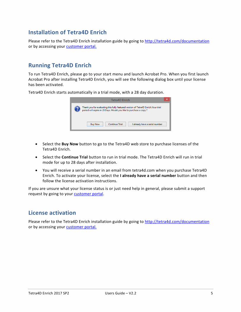
Running Tetra4D Enrich To run Tetra4D Enrich, please go to your start menu and launch Acrobat Pro. When you first launch Acrobat Pro after installing Tetra4D Enrich, you will see the following dialog box until your license has been activated.
Tetra4D Enrich starts automatically in a trial mode, with a 28 day duration.
• Select the Buy Now button to go to the Tetra4D web store to purchase licenses of the Tetra4D Enrich.
• Select the Continue Trial button to run in trial mode. The Tetra4D Enrich will run in trial mode for up to 28 days after installation.
• You will receive a serial number in an email from tetra4d.com when you purchase Tetra4D Enrich. To activate your license, select the I already have a serial number button and then follow the license activation instructions.
If you are unsure what your license status is or just need help in general, please submit a support request by going to your customer portal.
License activation Please refer to the Tetra4D Enrich installation guide by going to http://tetra4d.com/documentation or by accessing your customer portal.
Tetra4D Enrich 2017 SP2 Users Guide – V2.2 6
Chapter 2: Tetra4D Enrich overview Tetra4D Enrich allows you to create rich PDFs from supported 3D and CAD file formats, to consolidate this 3D information with other types of information (meta-data…), and to add into the PDF document advanced objects in order to ease the access to the product information.
Note: This user manual is based on the Acrobat Pro DC version of Tetra4D Enrich. All screen shots have been made using Acrobat Pro DC.
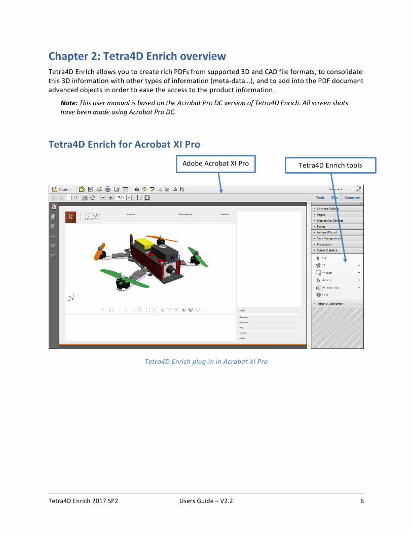
Tetra4D Enrich for Acrobat XI Pro
Tetra4D Enrich plug-in in Acrobat XI Pro
Tetra4D Enrich tools Adobe Acrobat XI Pro
Tetra4D Enrich 2017 SP2 Users Guide – V2.2 7
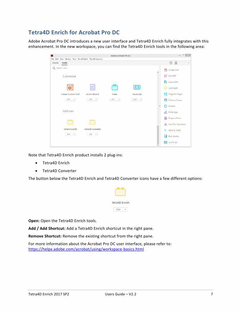
Tetra4D Enrich for Acrobat Pro DC Adobe Acrobat Pro DC introduces a new user interface and Tetra4D Enrich fully integrates with this enhancement. In the new workspace, you can find the Tetra4D Enrich tools in the following area:
Note that Tetra4D Enrich product installs 2 plug-ins:
• Tetra4D Enrich
• Tetra4D Converter
The button below the Tetra4D Enrich and Tetra4D Converter icons have a few different options:
Open: Open the Tetra4D Enrich tools.
Add / Add Shortcut: Add a Tetra4D Enrich shortcut in the right pane.
Remove Shortcut: Remove the existing shortcut from the right pane.
For more information about the Acrobat Pro DC user interface, please refer to: https://helpx.adobe.com/acrobat/using/workspace-basics.html
Tetra4D Enrich 2017 SP2 Users Guide – V2.2 8
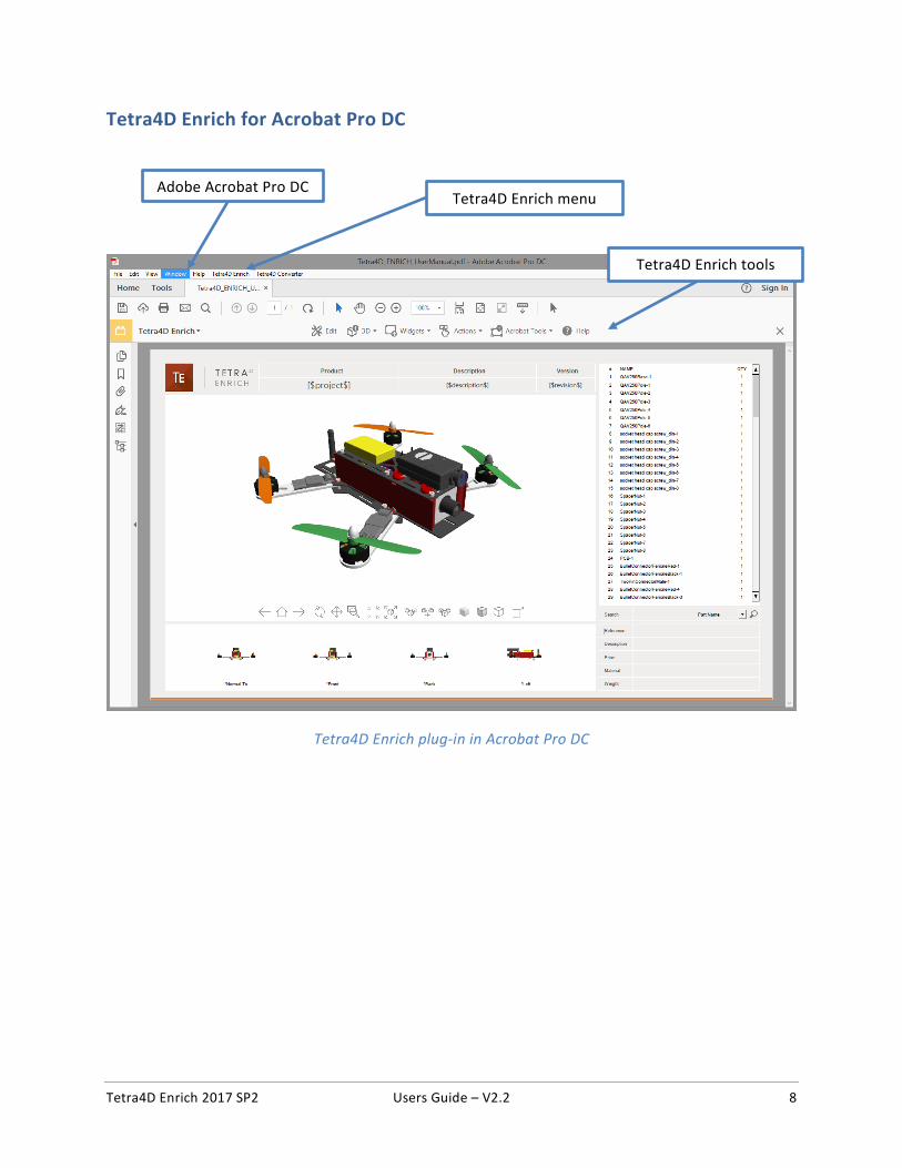
Tetra4D Enrich for Acrobat Pro DC
Tetra4D Enrich plug-in in Acrobat Pro DC
Tetra4D Enrich menu
Tetra4D Enrich tools
Adobe Acrobat Pro DC
Tetra4D Enrich 2017 SP2 Users Guide – V2.2 9
Chapter 3: Tetra4D Enrich features
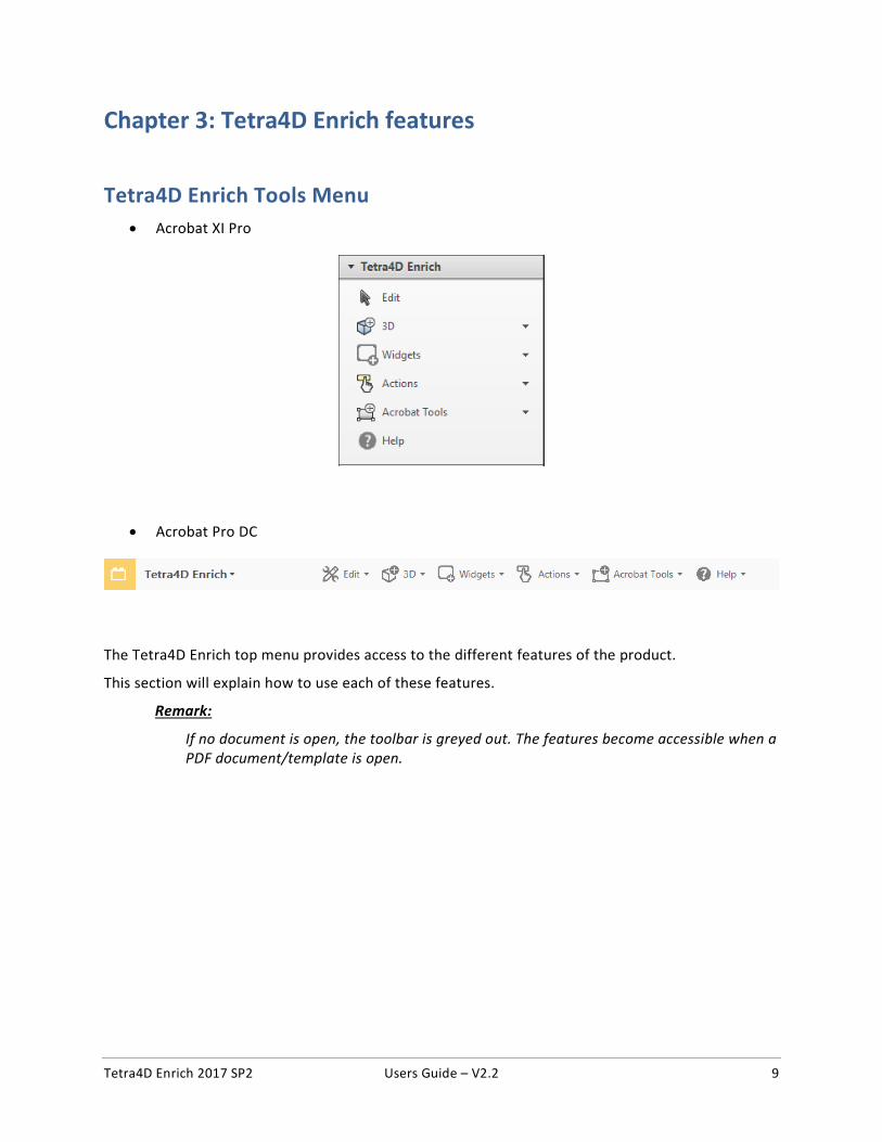
Tetra4D Enrich Tools Menu • Acrobat XI Pro
• Acrobat Pro DC
The Tetra4D Enrich top menu provides access to the different features of the product.
This section will explain how to use each of these features.
Remark:
If no document is open, the toolbar is greyed out. The features become accessible when a PDF document/template is open.
Tetra4D Enrich 2017 SP2 Users Guide – V2.2 10
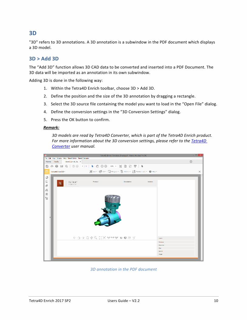
3D
"3D" refers to 3D annotations. A 3D annotation is a subwindow in the PDF document which displays a 3D model.
3D > Add 3D
The “Add 3D” function allows 3D CAD data to be converted and inserted into a PDF Document. The 3D data will be imported as an annotation in its own subwindow.
Adding 3D is done in the following way:
1. Within the Tetra4D Enrich toolbar, choose 3D > Add 3D.
2. Define the position and the size of the 3D annotation by dragging a rectangle.
3. Select the 3D source file containing the model you want to load in the “Open File” dialog.
4. Define the conversion settings in the “3D Conversion Settings” dialog.
5. Press the OK button to confirm.
Remark:
3D models are read by Tetra4D Converter, which is part of the Tetra4D Enrich product. For more information about the 3D conversion settings, please refer to the Tetra4D Converter user manual.
3D annotation in the PDF document
Tetra4D Enrich 2017 SP2 Users Guide – V2.2 11
3D > Add 3D attributes
The Add 3D attributes function allows you to import attributes (meta-data) from an external source, such as for example a PDM (Product Data Management), a PLM (Product Lifecycle Management), or an ERP (Enterprise Resource Planning) application.
Tetra4D Enrich will correlate these attributes with the 3D parts that are currently in the PDF document. They can then be accessed in a Table or displayed in text fields by defining Actions, just like the attributes that have been read from the native CAD data.
Remark:
The attributes are imported from XML files. The mapping between the attributes and the 3D parts must be defined in the XML file because it is performed at the time of import. See below the definition of the XML format and the mapping capabilities.
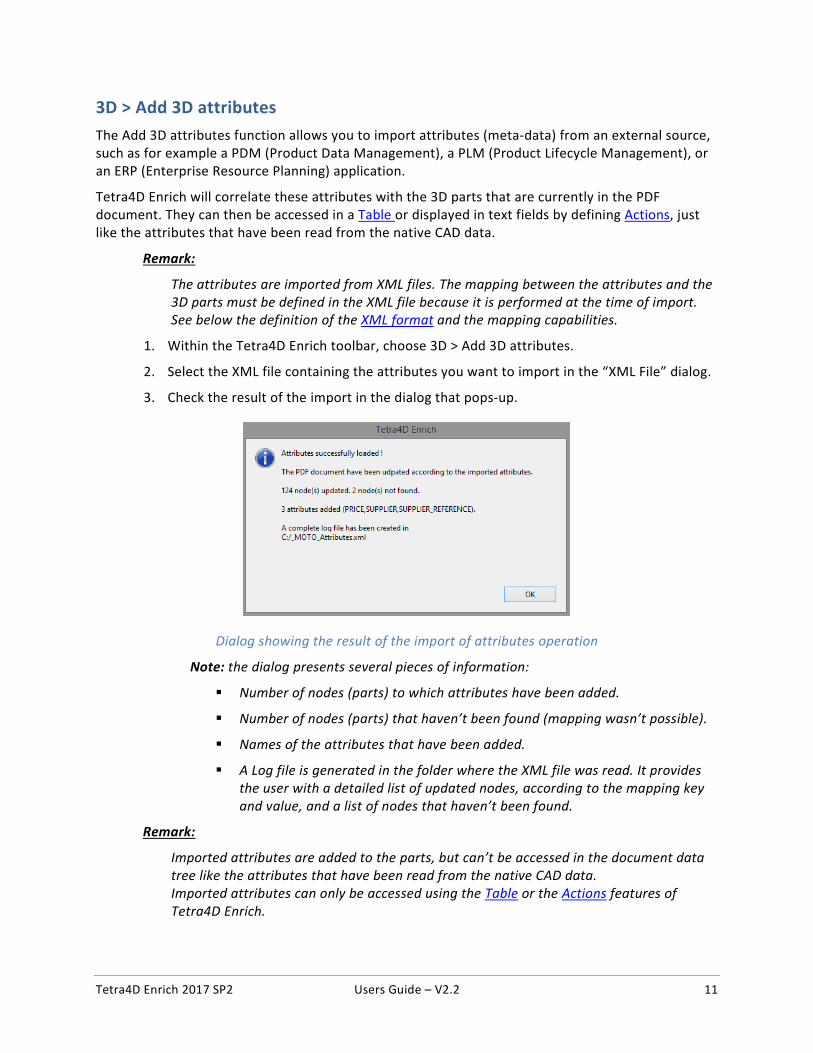
1. Within the Tetra4D Enrich toolbar, choose 3D > Add 3D attributes.
2. Select the XML file containing the attributes you want to import in the “XML File” dialog.
3. Check the result of the import in the dialog that pops-up.
Dialog showing the result of the import of attributes operation
Note: the dialog presents several pieces of information:
Number of nodes (parts) to which attributes have been added.
Number of nodes (parts) that haven’t been found (mapping wasn’t possible).
Names of the attributes that have been added.
A Log file is generated in the folder where the XML file was read. It provides the user with a detailed list of updated nodes, according to the mapping key and value, and a list of nodes that haven’t been found.
Remark:
Imported attributes are added to the parts, but can’t be accessed in the document data tree like the attributes that have been read from the native CAD data. Imported attributes can only be accessed using the Table or the Actions features of Tetra4D Enrich.
Tetra4D Enrich 2017 SP2 Users Guide – V2.2 12
Format of the XML file The XML file must contain all the required information to define new attributes and to add these attributes to the 3D data that is in the 3D annotation.
There are two different mapping methods:
• Based on the value of an attribute of the part.
• Based on the name of the part in the 3D annotation.
XML format, with a mapping based on the value of an attribute
• Example of a file: <attributes>
<ATTRIBUTE key="AttribName" attribute_value="AttribValuePart1">
<NEW_ATTRIB name="NewAttribName1" value="NewAttribName_Val1_Part1" />
<NEW_ATTRIB name="NewAttribName2" value="NewAttribName_Val2_Part1" />
</ATTRIBUTE>
<ATTRIBUTE key="AttribName" attribute_value="AttribValuePart2">
<NEW_ATTRIB name="NewAttribName1" value="NewAttribName_Val1_Part2" />
<NEW_ATTRIB name="NewAttribName2" value="NewAttribName_Val2_Part2" />
</ATTRIBUTE>
</attributes>
• Key for the mapping: <ATTRIBUTE key="AttribName" attribute_value="AttribValuePart1">
AttribName: Must be an existing attribute in the CAD file
AttribValuePart1: Value of the attribute of the part
• New attribute definition: <NEW_ATTRIB name="NewAttribName1" value="NewAttribName_Val1_Part1" />
NewAttribName1: Name of the new attribute
NewAttribName_Val1_Part1: Value of the new attribute for the part
Tetra4D Enrich 2017 SP2 Users Guide – V2.2 13
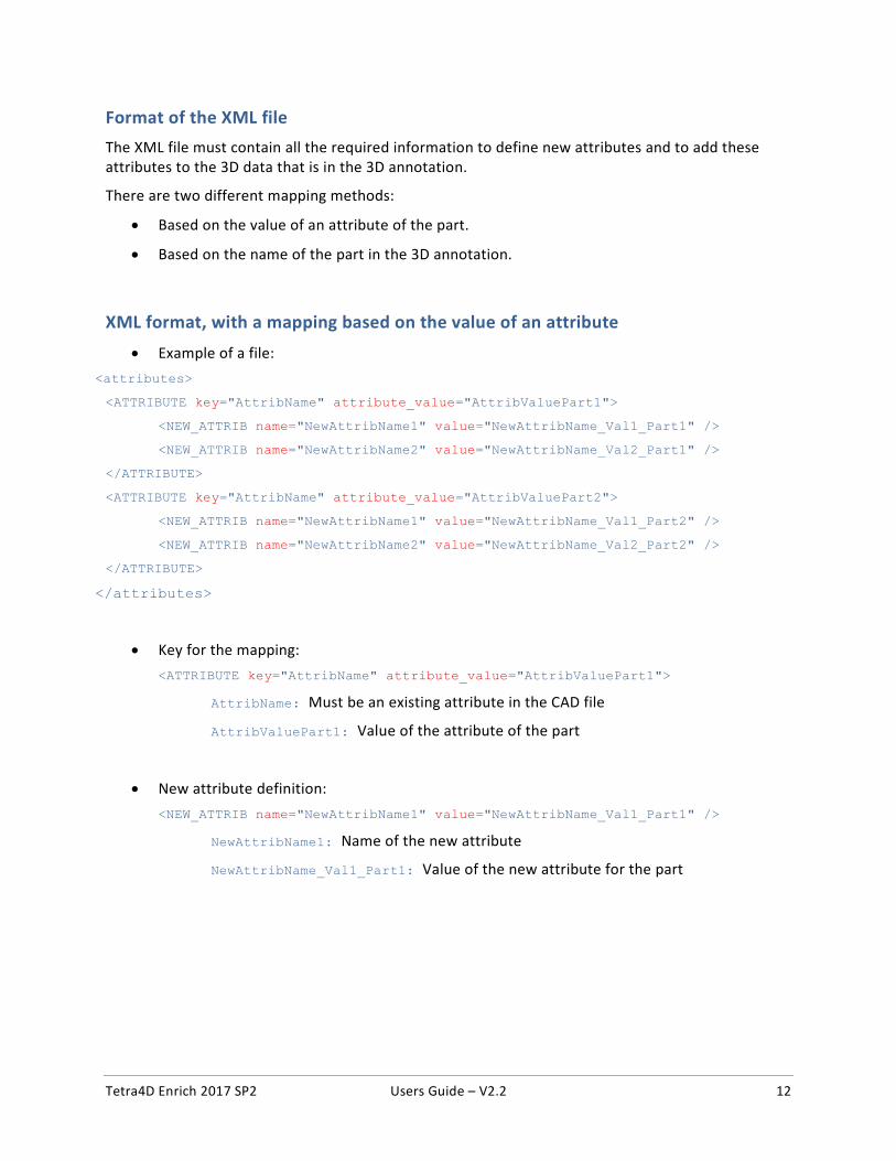
• Example:
o CAD model in the PDF document
Native CAD attributes for the 2 selected parts
o Imported XML file to add attributes <attributes>
<ATTRIBUTE key="ItemNumber" attribute_value="H1212556">
<NEW_ATTRIB name="SUPPLIER" value="Supplier A" />
<NEW_ATTRIB name="SUPPLIER_REFERENCE" value="RefA01" />
</ATTRIBUTE>
<ATTRIBUTE key="ItemNumber" attribute_value="H4114567">
<NEW_ATTRIB name="SUPPLIER" value="Supplier B" />
<NEW_ATTRIB name="SUPPLIER_REFERENCE" value="RefB01" />
</ATTRIBUTE>
</attributes>
mapping is performed using the ItemNumber attribute
2 attributes are added to the 3D parts: SUPPLIER and SUPPLIER_REFERENCE
Tetra4D Enrich 2017 SP2 Users Guide – V2.2 14
XML format, with a mapping based on name of the part in the 3D annotation • Example of a file:
<attributes>
<NAME key="PartName1">
<NEW_ATTRIB name="NewAttribName1" value="NewAttribName_Val1_Part1"/>
<NEW_ATTRIB name="NewAttribName2" value="NewAttribName_Val2_Part1"/>
</NAME>
<NAME key="PartName2">
<NEW_ATTRIB name="NewAttribName1" value="NewAttribName_Val1_Part2"/>
<NEW_ATTRIB name="NewAttribName2" value="NewAttribName_Val2_Part2"/>
</NAME>
</attributes>
• Key for the mapping: <NAME key="PartName1">
PartName1: Name of the part as shown in the data tree
• New attribute definition: <NEW_ATTRIB name="NewAttribName1" value="NewAttribName_Val1_Part1"/>
NewAttribName1: Name of the new attribute
NewAttribName_Val1_Part1: Value of the new attribute for the part
Tetra4D Enrich 2017 SP2 Users Guide – V2.2 15
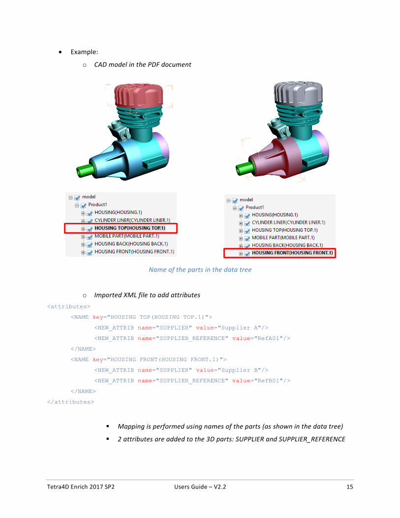
• Example:
o CAD model in the PDF document
Name of the parts in the data tree
o Imported XML file to add attributes <attributes>
<NAME key="HOUSING TOP(HOUSING TOP.1)">
<NEW_ATTRIB name="SUPPLIER" value="Supplier A"/>
<NEW_ATTRIB name="SUPPLIER_REFERENCE" value="RefA01"/>
</NAME>
<NAME key="HOUSING FRONT(HOUSING FRONT.1)">
<NEW_ATTRIB name="SUPPLIER" value="Supplier B"/>
<NEW_ATTRIB name="SUPPLIER_REFERENCE" value="RefB01"/>
</NAME>
</attributes>
Mapping is performed using names of the parts (as shown in the data tree)
2 attributes are added to the 3D parts: SUPPLIER and SUPPLIER_REFERENCE
Tetra4D Enrich 2017 SP2 Users Guide – V2.2 16
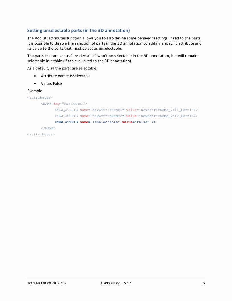
Setting unselectable parts (in the 3D annotation) The Add 3D attributes function allows you to also define some behavior settings linked to the parts. It is possible to disable the selection of parts in the 3D annotation by adding a specific attribute and its value to the parts that must be set as unselectable.
The parts that are set as “unselectable” won’t be selectable in the 3D annotation, but will remain selectable in a table (if table is linked to the 3D annotation).
As a default, all the parts are selectable.
• Attribute name: IsSelectable
• Value: False
Example <attributes>
<NAME key="PartName1">
<NEW_ATTRIB name="NewAttribName1" value="NewAttribName_Val1_Part1"/>
<NEW_ATTRIB name="NewAttribName2" value="NewAttribName_Val2_Part1"/>
<NEW_ATTRIB name="IsSelectable" value="False" />
</NAME>
</attributes>
Tetra4D Enrich 2017 SP2 Users Guide – V2.2 17
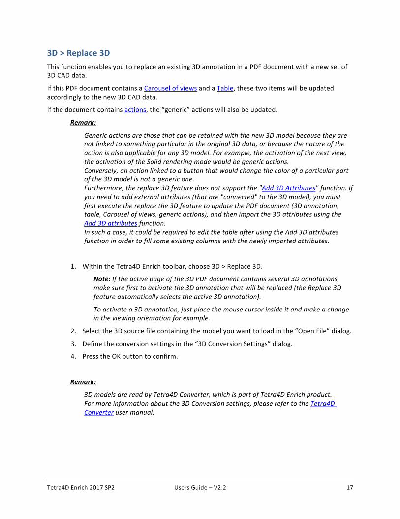
3D > Replace 3D
This function enables you to replace an existing 3D annotation in a PDF document with a new set of 3D CAD data.
If this PDF document contains a Carousel of views and a Table, these two items will be updated accordingly to the new 3D CAD data.
If the document contains actions, the “generic” actions will also be updated.
Remark:
Generic actions are those that can be retained with the new 3D model because they are not linked to something particular in the original 3D data, or because the nature of the action is also applicable for any 3D model. For example, the activation of the next view, the activation of the Solid rendering mode would be generic actions. Conversely, an action linked to a button that would change the color of a particular part of the 3D model is not a generic one. Furthermore, the replace 3D feature does not support the "Add 3D Attributes" function. If you need to add external attributes (that are "connected" to the 3D model), you must first execute the replace the 3D feature to update the PDF document (3D annotation, table, Carousel of views, generic actions), and then import the 3D attributes using the Add 3D attributes function. In such a case, it could be required to edit the table after using the Add 3D attributes function in order to fill some existing columns with the newly imported attributes.
1. Within the Tetra4D Enrich toolbar, choose 3D > Replace 3D.
Note: If the active page of the 3D PDF document contains several 3D annotations, make sure first to activate the 3D annotation that will be replaced (the Replace 3D feature automatically selects the active 3D annotation).
To activate a 3D annotation, just place the mouse cursor inside it and make a change in the viewing orientation for example.
2. Select the 3D source file containing the model you want to load in the “Open File” dialog.
3. Define the conversion settings in the “3D Conversion Settings” dialog.
4. Press the OK button to confirm.
Remark:
3D models are read by Tetra4D Converter, which is part of Tetra4D Enrich product. For more information about the 3D Conversion settings, please refer to the Tetra4D Converter user manual.
Tetra4D Enrich 2017 SP2 Users Guide – V2.2 18
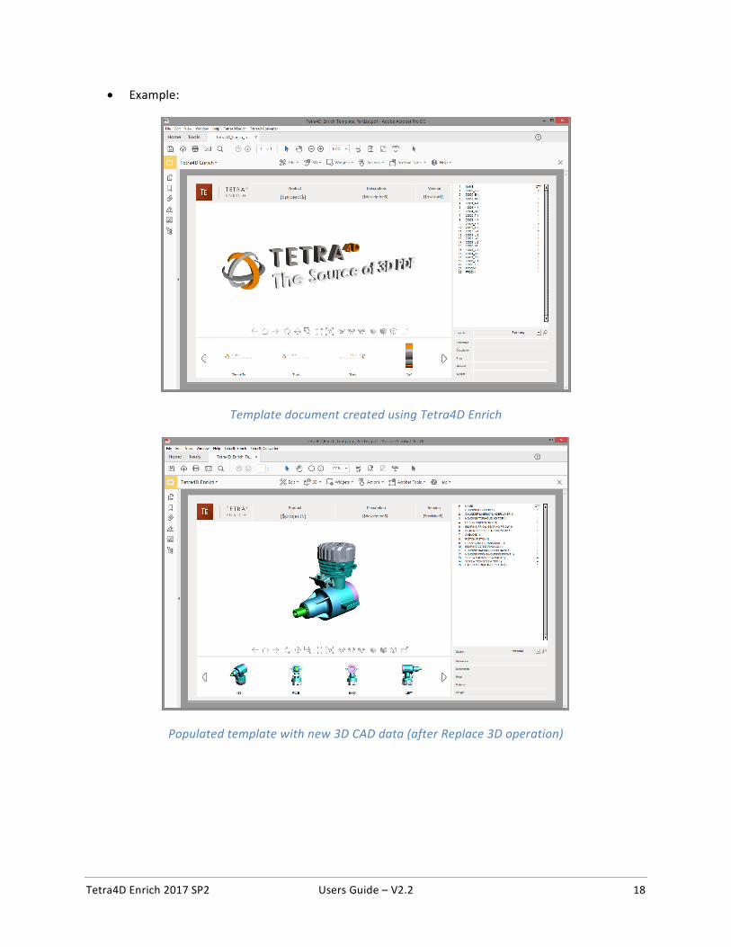
• Example:
Template document created using Tetra4D Enrich
Populated template with new 3D CAD data (after Replace 3D operation)
Tetra4D Enrich 2017 SP2 Users Guide – V2.2 19
Widgets
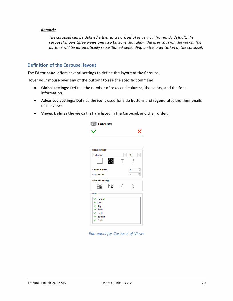
Widget > Add Carousel The carousel of views is a widget that can be inserted in the PDF document to list the 3D views. The views are presented as image thumbnails, allowing the user to easily browse and activate one. To activate a view, click on its thumbnail. The 3D annotation will then transition to that view.
A carousel of views
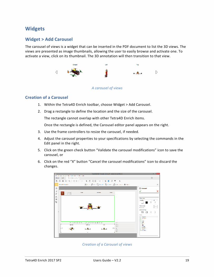
Creation of a Carousel 1. Within the Tetra4D Enrich toolbar, choose Widget > Add Carousel.
2. Drag a rectangle to define the location and the size of the carousel.
The rectangle cannot overlap with other Tetra4D Enrich items.
Once the rectangle is defined, the Carousel editor panel appears on the right.
3. Use the frame controllers to resize the carousel, if needed.
4. Adjust the carousel properties to your specifications by selecting the commands in the Edit panel in the right.
5. Click on the green check button “Validate the carousel modifications” icon to save the carousel, or
6. Click on the red “X” button “Cancel the carousel modifications” icon to discard the changes.
Creation of a Carousel of views
Tetra4D Enrich 2017 SP2 Users Guide – V2.2 20
Remark:
The carousel can be defined either as a horizontal or vertical frame. By default, the carousel shows three views and two buttons that allow the user to scroll the views. The buttons will be automatically repositioned depending on the orientation of the carousel.
Definition of the Carousel layout
The Editor panel offers several settings to define the layout of the Carousel.
Hover your mouse over any of the buttons to see the specific command.
• Global settings: Defines the number of rows and columns, the colors, and the font information.
• Advanced settings: Defines the icons used for side buttons and regenerates the thumbnails of the views.
• Views: Defines the views that are listed in the Carousel, and their order.
Edit panel for Carousel of Views
Tetra4D Enrich 2017 SP2 Users Guide – V2.2 21
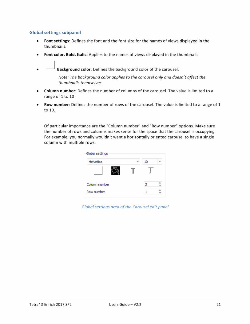
Global settings subpanel
• Font settings: Defines the font and the font size for the names of views displayed in the thumbnails.
• Font color, Bold, Italic: Applies to the names of views displayed in the thumbnails.
• Background color: Defines the background color of the carousel.
Note: The background color applies to the carousel only and doesn’t affect the thumbnails themselves.
• Column number: Defines the number of columns of the carousel. The value is limited to a range of 1 to 10
• Row number: Defines the number of rows of the carousel. The value is limited to a range of 1 to 10.
Of particular importance are the "Column number" and "Row number" options. Make sure the number of rows and columns makes sense for the space that the carousel is occupying. For example, you normally wouldn't want a horizontally oriented carousel to have a single column with multiple rows.
Global settings area of the Carousel edit panel
Tetra4D Enrich 2017 SP2 Users Guide – V2.2 22
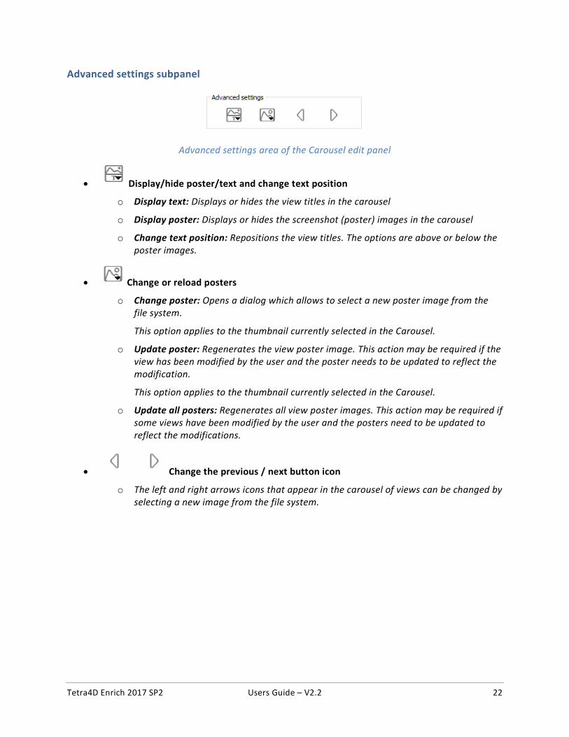
Advanced settings subpanel
Advanced settings area of the Carousel edit panel
• Display/hide poster/text and change text position
o Display text: Displays or hides the view titles in the carousel
o Display poster: Displays or hides the screenshot (poster) images in the carousel
o Change text position: Repositions the view titles. The options are above or below the poster images.
• Change or reload posters
o Change poster: Opens a dialog which allows to select a new poster image from the file system.
This option applies to the thumbnail currently selected in the Carousel.
o Update poster: Regenerates the view poster image. This action may be required if the view has been modified by the user and the poster needs to be updated to reflect the modification.
This option applies to the thumbnail currently selected in the Carousel.
o Update all posters: Regenerates all view poster images. This action may be required if some views have been modified by the user and the posters need to be updated to reflect the modifications.
• Change the previous / next button icon
o The left and right arrows icons that appear in the carousel of views can be changed by selecting a new image from the file system.
Tetra4D Enrich 2017 SP2 Users Guide – V2.2 23
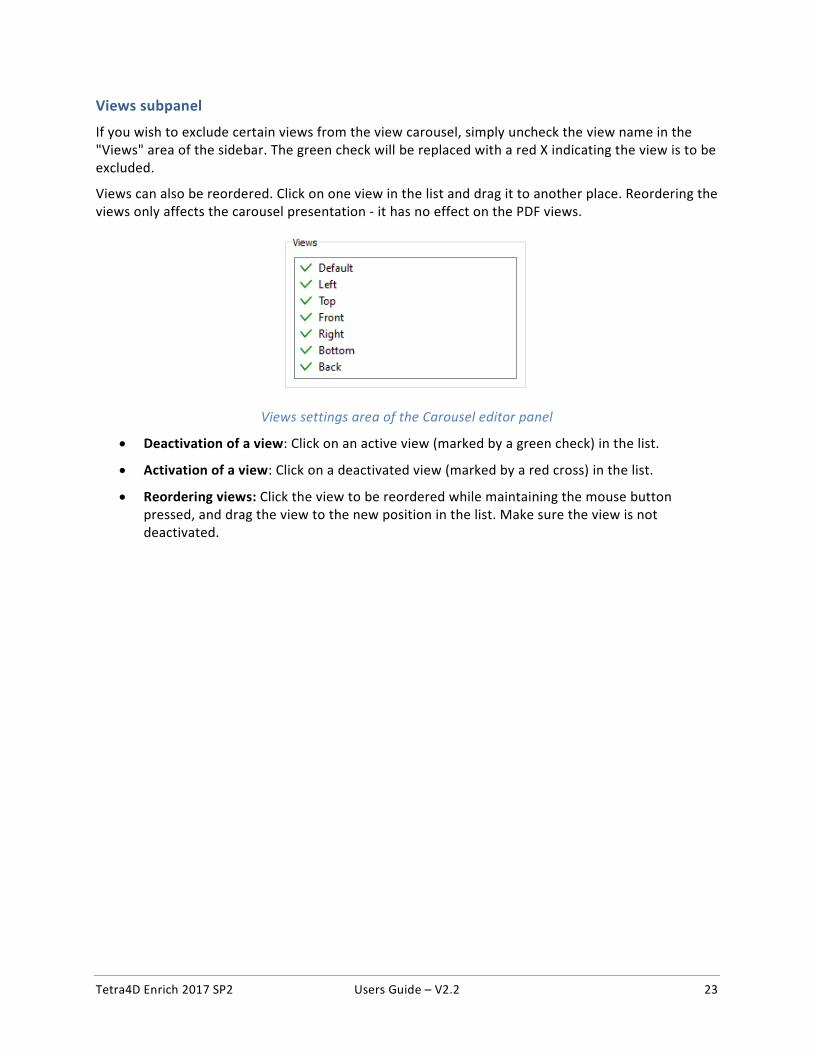
Views subpanel
If you wish to exclude certain views from the view carousel, simply uncheck the view name in the "Views" area of the sidebar. The green check will be replaced with a red X indicating the view is to be excluded.
Views can also be reordered. Click on one view in the list and drag it to another place. Reordering the views only affects the carousel presentation - it has no effect on the PDF views.
Views settings area of the Carousel editor panel
• Deactivation of a view: Click on an active view (marked by a green check) in the list.
• Activation of a view: Click on a deactivated view (marked by a red cross) in the list.
• Reordering views: Click the view to be reordered while maintaining the mouse button pressed, and drag the view to the new position in the list. Make sure the view is not deactivated.
Tetra4D Enrich 2017 SP2 Users Guide – V2.2 24
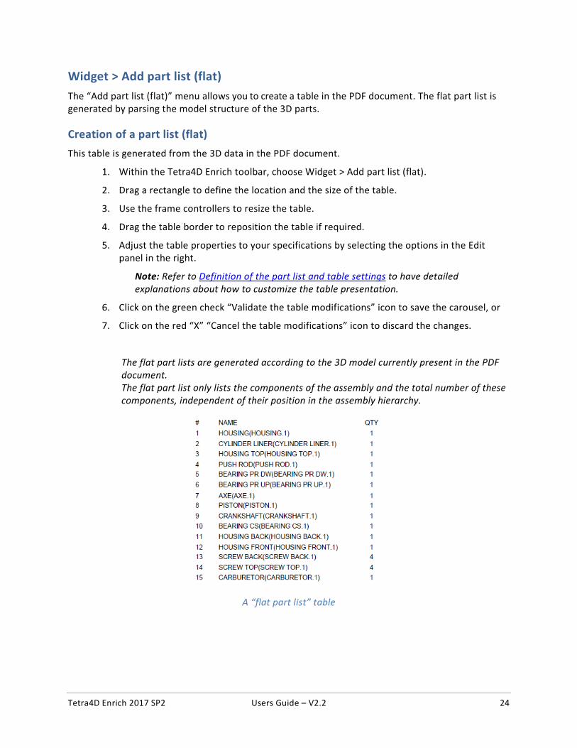
Widget > Add part list (flat)
The “Add part list (flat)” menu allows you to create a table in the PDF document. The flat part list is generated by parsing the model structure of the 3D parts.
Creation of a part list (flat)
This table is generated from the 3D data in the PDF document.
1. Within the Tetra4D Enrich toolbar, choose Widget > Add part list (flat).
2. Drag a rectangle to define the location and the size of the table.
3. Use the frame controllers to resize the table.
4. Drag the table border to reposition the table if required.
5. Adjust the table properties to your specifications by selecting the options in the Edit panel in the right.
Note: Refer to Definition of the part list and table settings to have detailed explanations about how to customize the table presentation.
6. Click on the green check “Validate the table modifications” icon to save the carousel, or
7. Click on the red “X” “Cancel the table modifications” icon to discard the changes.
The flat part lists are generated according to the 3D model currently present in the PDF document. The flat part list only lists the components of the assembly and the total number of these components, independent of their position in the assembly hierarchy.
A “flat part list” table
Tetra4D Enrich 2017 SP2 Users Guide – V2.2 25
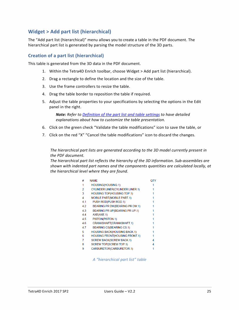
Widget > Add part list (hierarchical)
The “Add part list (hierarchical)” menu allows you to create a table in the PDF document. The hierarchical part list is generated by parsing the model structure of the 3D parts.
Creation of a part list (hierarchical)
This table is generated from the 3D data in the PDF document.
1. Within the Tetra4D Enrich toolbar, choose Widget > Add part list (hierarchical).
2. Drag a rectangle to define the location and the size of the table.
3. Use the frame controllers to resize the table.
4. Drag the table border to reposition the table if required.
5. Adjust the table properties to your specifications by selecting the options in the Edit panel in the right.
Note: Refer to Definition of the part list and table settings to have detailed explanations about how to customize the table presentation.
6. Click on the green check “Validate the table modifications” icon to save the table, or
7. Click on the red “X” “Cancel the table modifications” icon to discard the changes.
The hierarchical part lists are generated according to the 3D model currently present in the PDF document. The hierarchical part list reflects the hierarchy of the 3D information. Sub-assemblies are shown with indented part names and the components quantities are calculated locally, at the hierarchical level where they are found.
A “hierarchical part list” table
Tetra4D Enrich 2017 SP2 Users Guide – V2.2 26
Widget > Add table from CSV
The “Add a table from CSV” menu allows you to create a table in the PDF document from external data defined in a CSV.
Creation of a table from CSV
This table is generated from a chosen CSV file.
1. Within the Tetra4D Enrich toolbar, choose Widget > Add table from CSV.
2. Drag a rectangle to define the location and the size of the table.
3. Use the frame controllers to resize the table if required.
4. Drag the table border to reposition the table if required.
5. Adjust the table properties to your specifications by selecting the options in the Edit panel in the right.
Note: Refer to Definition of the part list and table settings to have detailed explanations about how to customize the table presentation.
6. Click on the green check “Validate the table modifications” icon to save the carousel, or
7. Click on the red “X” “Cancel the table modifications” icon to discard the changes.
Table created from a CSV file has no link with the 3D parts of the 3D annotation. To map table rows with 3D parts, refer to “3D Attributes / 3D Mapping” section. To create actions triggered by a selection of a row of the table, refer to “On table row” section.
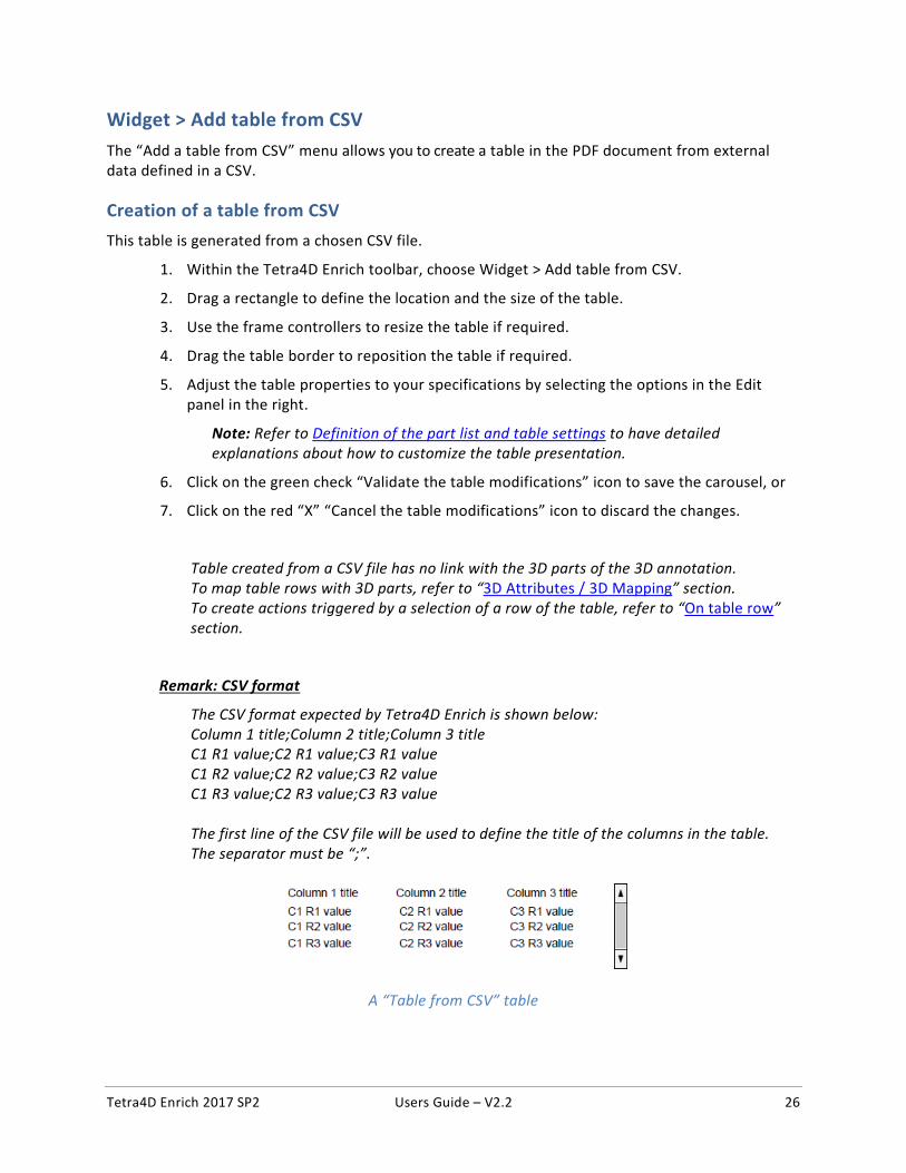
Remark: CSV format
The CSV format expected by Tetra4D Enrich is shown below: Column 1 title;Column 2 title;Column 3 title C1 R1 value;C2 R1 value;C3 R1 value C1 R2 value;C2 R2 value;C3 R2 value C1 R3 value;C2 R3 value;C3 R3 value The first line of the CSV file will be used to define the title of the columns in the table. The separator must be “;”.
A “Table from CSV” table
Tetra4D Enrich 2017 SP2 Users Guide – V2.2 27
Widget > Add table from clipboard
The “Add a table from clipboard” menu allows you to create a table in the PDF document from the system clipboard.
Creation of a table from clipboard
A table can be defined using data that is stored on the system clipboard. This is very similar to adding the table from a CSV file – the only difference is that instead of showing a dialog to select a CSV file, Tetra4 Enrich will grab the data automatically from the clipboard.
1. Make sure the clipboard contains the table information. Then, within the Tetra4D Enrich toolbar, choose Widget > Add table from clipboard.
2. Drag a rectangle to define the location and the size of the table.
3. Use the frame controllers to resize the table.
4. Drag the table border to reposition the table if required.
5. Adjust the table properties to your specifications by selecting the options in the Edit panel in the right.
Note: Refer to Definition of the part list and table settings to have detailed explanations about how to customize the table presentation.
6. Click on the green check “Validate the table modifications” icon to save the table, or
7. Click on the red “X” “Cancel the table modifications” icon to discard the changes.
Tables created from the clipboard have no link with the 3D parts of the 3D annotation. To map table rows with 3D parts, refer to “3D Attributes / 3D Mapping”. To create actions triggered by a selection of a row of the table, refer to “On table row” section.
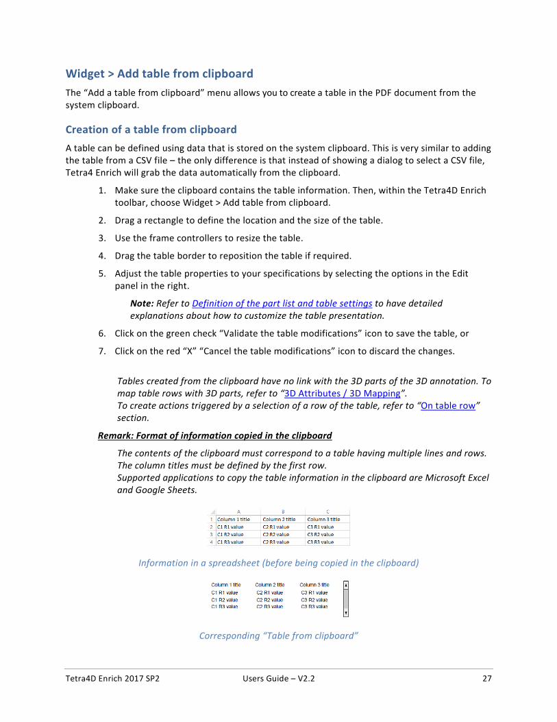
Remark: Format of information copied in the clipboard
The contents of the clipboard must correspond to a table having multiple lines and rows. The column titles must be defined by the first row. Supported applications to copy the table information in the clipboard are Microsoft Excel and Google Sheets.
Information in a spreadsheet (before being copied in the clipboard)
Corresponding “Table from clipboard”
Tetra4D Enrich 2017 SP2 Users Guide – V2.2 28
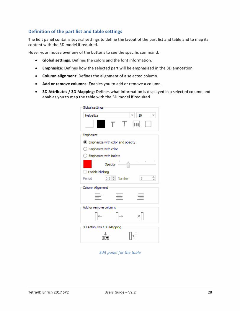
Definition of the part list and table settings
The Edit panel contains several settings to define the layout of the part list and table and to map its content with the 3D model if required.
Hover your mouse over any of the buttons to see the specific command.
• Global settings: Defines the colors and the font information.
• Emphasize: Defines how the selected part will be emphasized in the 3D annotation.
• Column alignment: Defines the alignment of a selected column.
• Add or remove columns: Enables you to add or remove a column.
• 3D Attributes / 3D Mapping: Defines what information is displayed in a selected column and enables you to map the table with the 3D model if required.
Edit panel for the table
Tetra4D Enrich 2017 SP2 Users Guide – V2.2 29
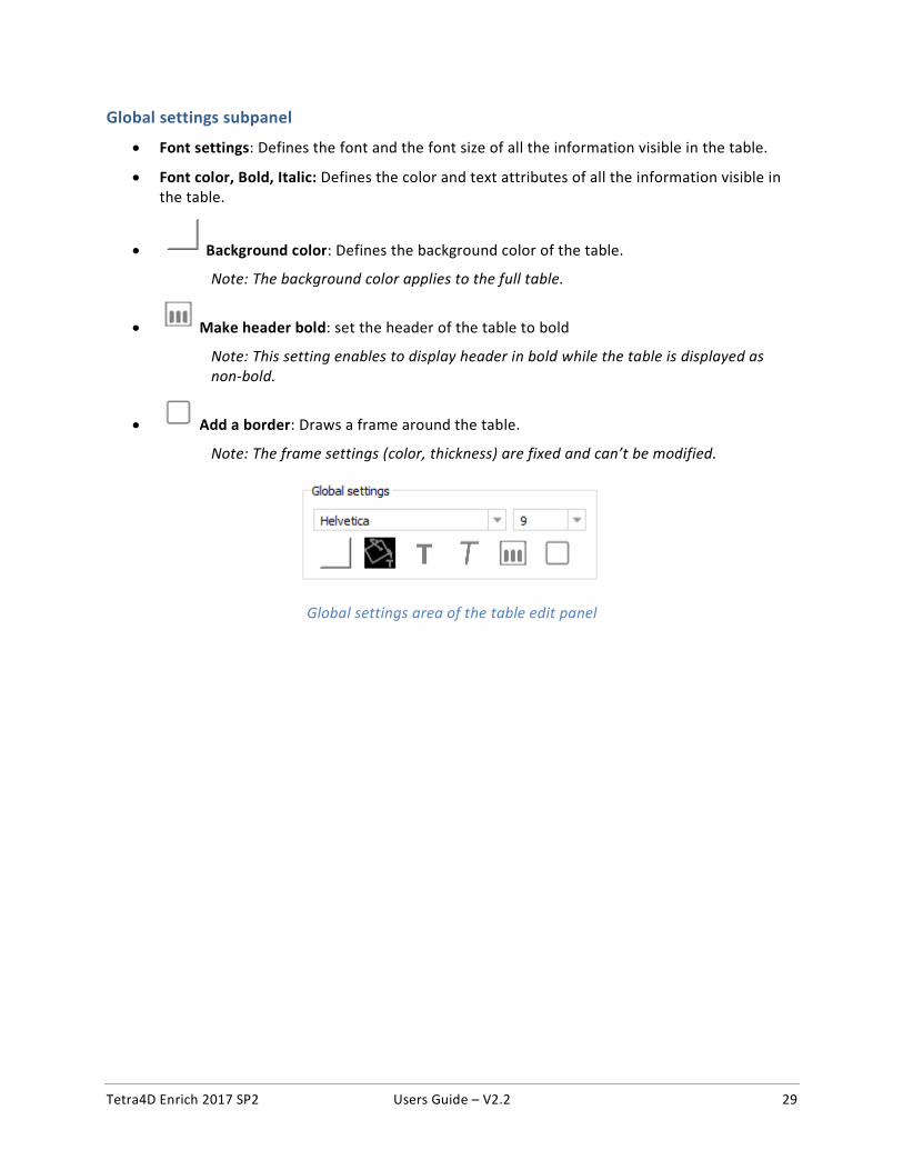
Global settings subpanel
• Font settings: Defines the font and the font size of all the information visible in the table.
• Font color, Bold, Italic: Defines the color and text attributes of all the information visible in the table.
• Background color: Defines the background color of the table.
Note: The background color applies to the full table.
• Make header bold: set the header of the table to bold
Note: This setting enables to display header in bold while the table is displayed as non-bold.
• Add a border: Draws a frame around the table.
Note: The frame settings (color, thickness) are fixed and can’t be modified.
Global settings area of the table edit panel
Tetra4D Enrich 2017 SP2 Users Guide – V2.2 30
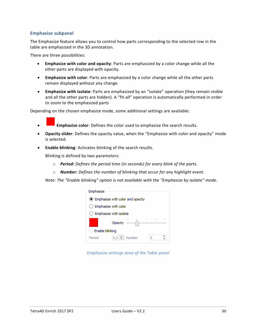
Emphasize subpanel
The Emphasize feature allows you to control how parts corresponding to the selected row in the table are emphasized in the 3D annotation.
There are three possibilities:
• Emphasize with color and opacity: Parts are emphasized by a color change while all the other parts are displayed with opacity.
• Emphasize with color: Parts are emphasized by a color change while all the other parts remain displayed without any change.
• Emphasize with isolate: Parts are emphasized by an “isolate” operation (they remain visible and all the other parts are hidden). A “fit-all” operation is automatically performed in order to zoom to the emphasized parts
Depending on the chosen emphasize mode, some additional settings are available:
• Emphasize color: Defines the color used to emphasize the search results.
• Opacity slider: Defines the opacity value, when the “Emphasize with color and opacity” mode is selected.
• Enable blinking: Activates blinking of the search results.
Blinking is defined by two parameters:
o Period: Defines the period time (in seconds) for every blink of the parts.
o Number: Defines the number of blinking that occur for any highlight event.
Note: The “Enable blinking” option is not available with the “Emphasize by isolate” mode.
Emphasize settings area of the Table panel
Tetra4D Enrich 2017 SP2 Users Guide – V2.2 31
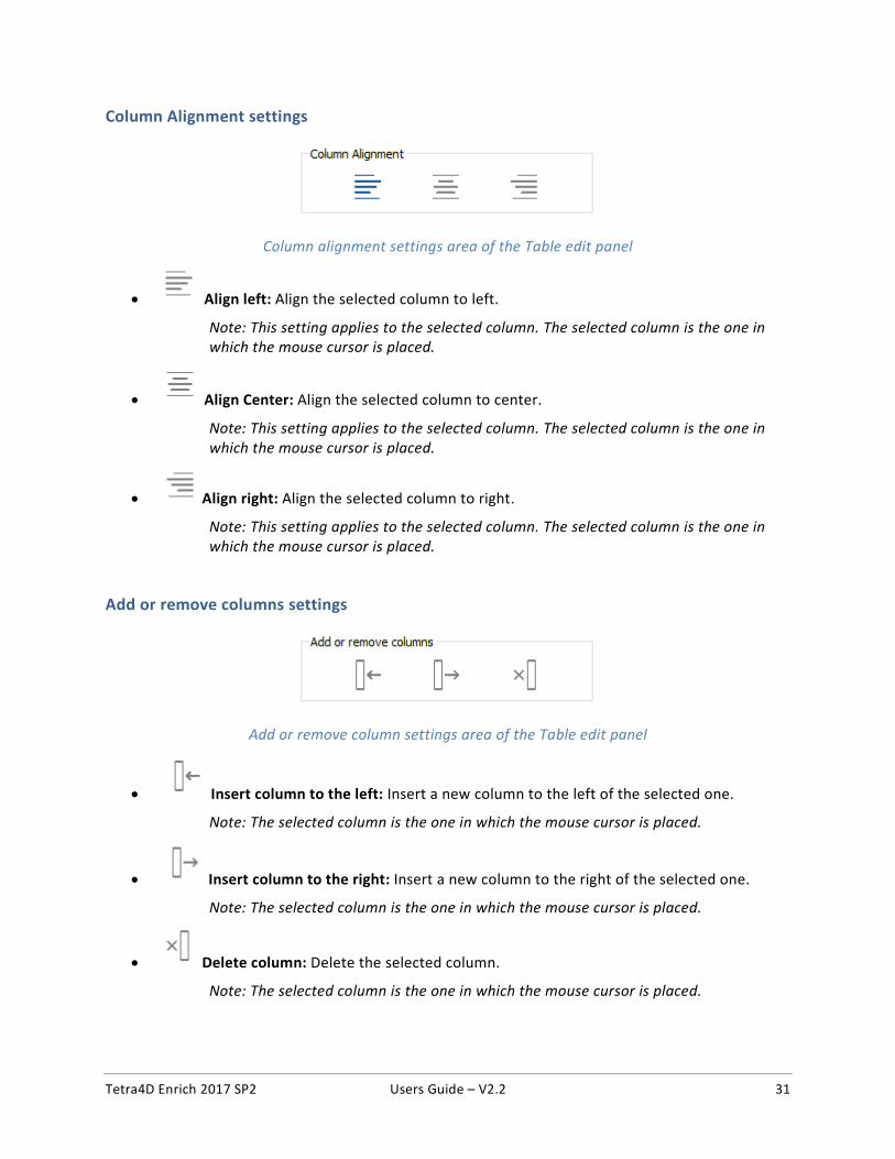
Column Alignment settings
Column alignment settings area of the Table edit panel
• Align left: Align the selected column to left.
Note: This setting applies to the selected column. The selected column is the one in which the mouse cursor is placed.
• Align Center: Align the selected column to center.
Note: This setting applies to the selected column. The selected column is the one in which the mouse cursor is placed.
• Align right: Align the selected column to right.
Note: This setting applies to the selected column. The selected column is the one in which the mouse cursor is placed.
Add or remove columns settings
Add or remove column settings area of the Table edit panel
• Insert column to the left: Insert a new column to the left of the selected one.
Note: The selected column is the one in which the mouse cursor is placed.
• Insert column to the right: Insert a new column to the right of the selected one.
Note: The selected column is the one in which the mouse cursor is placed.
• Delete column: Delete the selected column.
Note: The selected column is the one in which the mouse cursor is placed.
Tetra4D Enrich 2017 SP2 Users Guide – V2.2 32
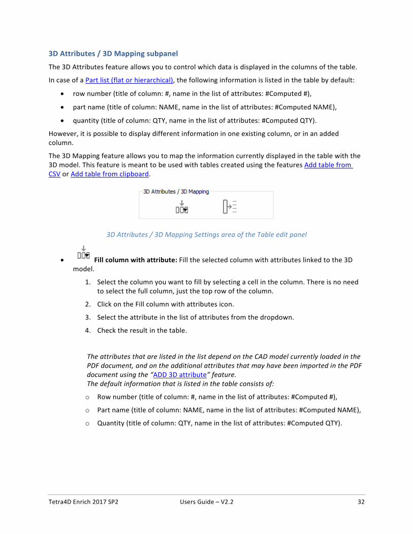
3D Attributes / 3D Mapping subpanel
The 3D Attributes feature allows you to control which data is displayed in the columns of the table.
In case of a Part list (flat or hierarchical), the following information is listed in the table by default:
• row number (title of column: #, name in the list of attributes: #Computed #),
• part name (title of column: NAME, name in the list of attributes: #Computed NAME),
• quantity (title of column: QTY, name in the list of attributes: #Computed QTY).
However, it is possible to display different information in one existing column, or in an added column.
The 3D Mapping feature allows you to map the information currently displayed in the table with the 3D model. This feature is meant to be used with tables created using the features Add table from CSV or Add table from clipboard.
3D Attributes / 3D Mapping Settings area of the Table edit panel
• Fill column with attribute: Fill the selected column with attributes linked to the 3D model.
1. Select the column you want to fill by selecting a cell in the column. There is no need to select the full column, just the top row of the column.
2. Click on the Fill column with attributes icon.
3. Select the attribute in the list of attributes from the dropdown.
4. Check the result in the table.
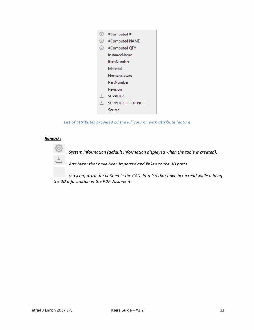
The attributes that are listed in the list depend on the CAD model currently loaded in the PDF document, and on the additional attributes that may have been imported in the PDF document using the “ADD 3D attribute” feature. The default information that is listed in the table consists of:
o Row number (title of column: #, name in the list of attributes: #Computed #),
o Part name (title of column: NAME, name in the list of attributes: #Computed NAME),
o Quantity (title of column: QTY, name in the list of attributes: #Computed QTY).
Tetra4D Enrich 2017 SP2 Users Guide – V2.2 33
List of attributes provided by the Fill column with attribute feature
Remark:
: System information (default information displayed when the table is created).
: Attributes that have been imported and linked to the 3D parts.
: (no icon) Attribute defined in the CAD data (so that have been read while adding the 3D information in the PDF document.
Tetra4D Enrich 2017 SP2 Users Guide – V2.2 34
• Map selected column with 3D parts: Use the selected column to map the rows of the table with the 3D parts.
1. Create the table using “Add table from CSV” or “Add table from clipboard” features.
Note: See detailed explanations on “Add table from CSV” or “Add table from clipboard”.
2. Select the column you want to use as a key for the mapping by selecting a cell in the column.
Note: An example is provided next page.
3. Click on the Map selected column with 3D parts icon.
4. Check the result of the mapping in the dialog that pops-up.
5. Click OK to close the dialog.
The “Map selected column with 3D parts” feature is available with tables created using the “Add table from CSV” or “Add table from clipboard” features. In the case of a table created using the Part list (flat or hierarchical) feature, this function will not be active, because these tables are already linked with the 3D data. Mapping the rows of the table with 3D parts enables a cross-highlight between the table and the 3D annotation, when selecting a row in the table or when selecting a part in the 3D annotation. The “mapping” means “correlate the values from this column to the corresponding 3D part”. The column title is important, because it is the key used to perform the mapping. For example, if the column title is “ItemNumber”, the mapping will work if the 3D parts contain an attribute named “ItemNumber”. Enrich will look for all the parts, and make the mapping between the table row and a particular part that matches ItemNumber.
Tetra4D Enrich 2017 SP2 Users Guide – V2.2 35
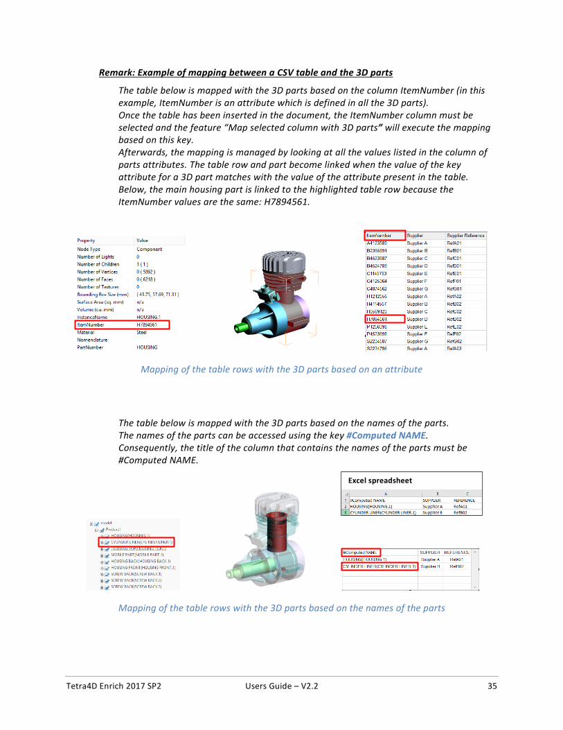
Remark: Example of mapping between a CSV table and the 3D parts
The table below is mapped with the 3D parts based on the column ItemNumber (in this example, ItemNumber is an attribute which is defined in all the 3D parts). Once the table has been inserted in the document, the ItemNumber column must be selected and the feature “Map selected column with 3D parts” will execute the mapping based on this key. Afterwards, the mapping is managed by looking at all the values listed in the column of parts attributes. The table row and part become linked when the value of the key attribute for a 3D part matches with the value of the attribute present in the table. Below, the main housing part is linked to the highlighted table row because the ItemNumber values are the same: H7894561.
Mapping of the table rows with the 3D parts based on an attribute
The table below is mapped with the 3D parts based on the names of the parts. The names of the parts can be accessed using the key #Computed NAME. Consequently, the title of the column that contains the names of the parts must be #Computed NAME.
Mapping of the table rows with the 3D parts based on the names of the parts
Excel spreadsheet
Tetra4D Enrich 2017 SP2 Users Guide – V2.2 36
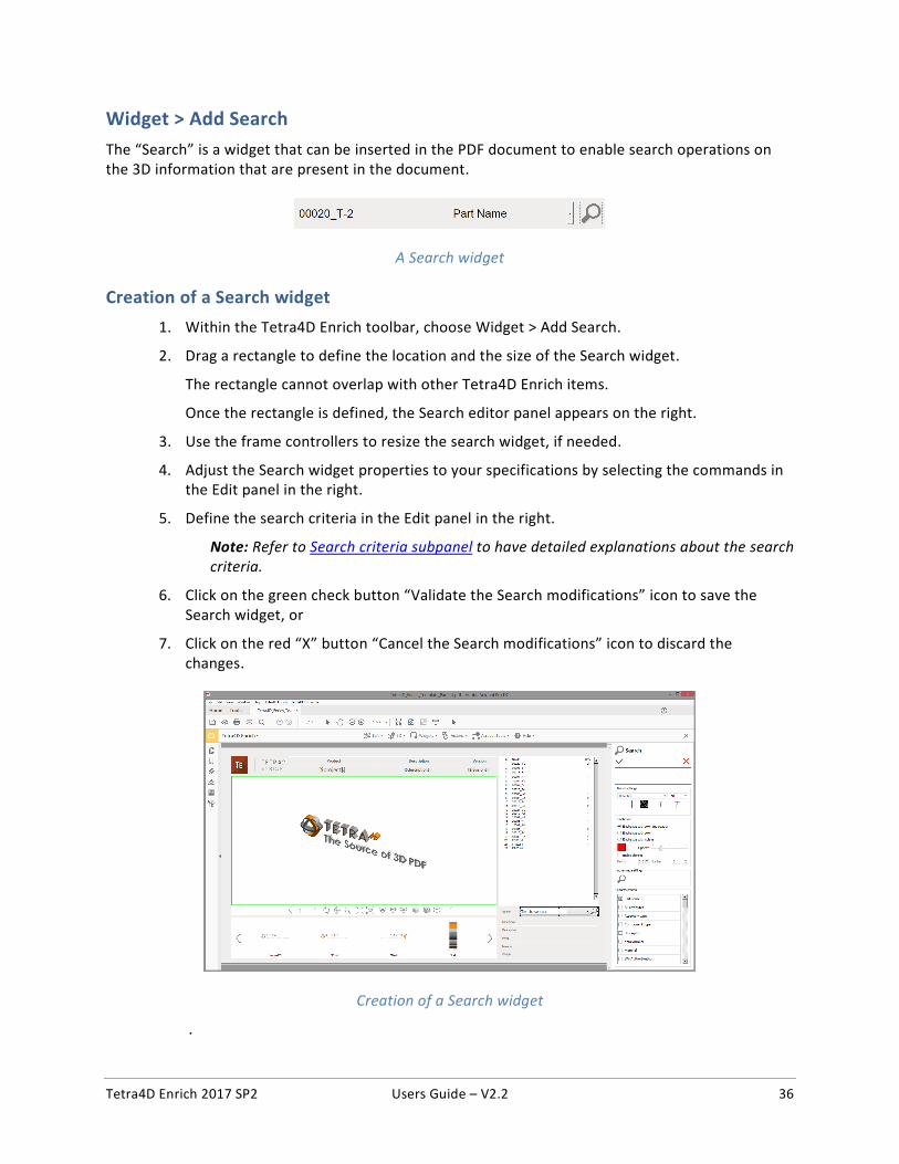
Widget > Add Search
The “Search” is a widget that can be inserted in the PDF document to enable search operations on the 3D information that are present in the document.
A Search widget
Creation of a Search widget
1. Within the Tetra4D Enrich toolbar, choose Widget > Add Search.
2. Drag a rectangle to define the location and the size of the Search widget.
The rectangle cannot overlap with other Tetra4D Enrich items.
Once the rectangle is defined, the Search editor panel appears on the right.
3. Use the frame controllers to resize the search widget, if needed.
4. Adjust the Search widget properties to your specifications by selecting the commands in the Edit panel in the right.
5. Define the search criteria in the Edit panel in the right.
Note: Refer to Search criteria subpanel to have detailed explanations about the search criteria.
6. Click on the green check button “Validate the Search modifications” icon to save the Search widget, or
7. Click on the red “X” button “Cancel the Search modifications” icon to discard the changes.
Creation of a Search widget
.
Tetra4D Enrich 2017 SP2 Users Guide – V2.2 37
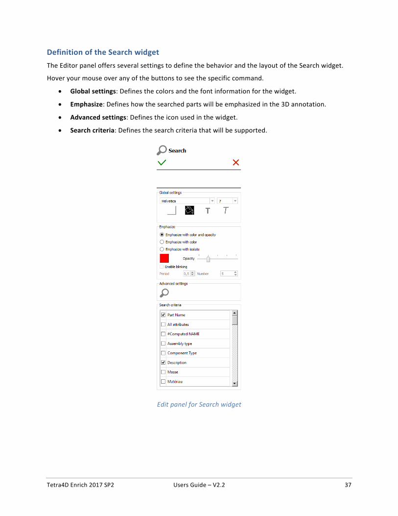
Definition of the Search widget
The Editor panel offers several settings to define the behavior and the layout of the Search widget.
Hover your mouse over any of the buttons to see the specific command.
• Global settings: Defines the colors and the font information for the widget.
• Emphasize: Defines how the searched parts will be emphasized in the 3D annotation.
• Advanced settings: Defines the icon used in the widget.
• Search criteria: Defines the search criteria that will be supported.
Edit panel for Search widget
Tetra4D Enrich 2017 SP2 Users Guide – V2.2 38
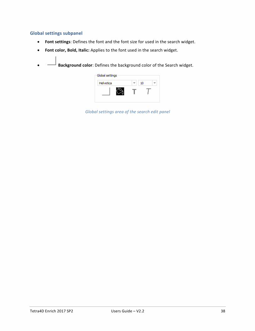
Global settings subpanel
• Font settings: Defines the font and the font size for used in the search widget.
• Font color, Bold, Italic: Applies to the font used in the search widget.
• Background color: Defines the background color of the Search widget.
Global settings area of the search edit panel
Tetra4D Enrich 2017 SP2 Users Guide – V2.2 39
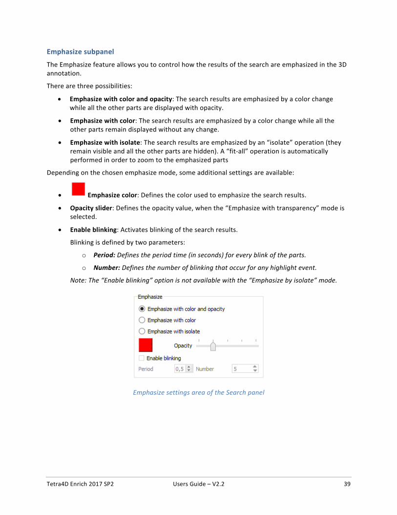
Emphasize subpanel
The Emphasize feature allows you to control how the results of the search are emphasized in the 3D annotation.
There are three possibilities:
• Emphasize with color and opacity: The search results are emphasized by a color change while all the other parts are displayed with opacity.
• Emphasize with color: The search results are emphasized by a color change while all the other parts remain displayed without any change.
• Emphasize with isolate: The search results are emphasized by an “isolate” operation (they remain visible and all the other parts are hidden). A “fit-all” operation is automatically performed in order to zoom to the emphasized parts
Depending on the chosen emphasize mode, some additional settings are available:
• Emphasize color: Defines the color used to emphasize the search results.
• Opacity slider: Defines the opacity value, when the “Emphasize with transparency” mode is selected.
• Enable blinking: Activates blinking of the search results.
Blinking is defined by two parameters:
o Period: Defines the period time (in seconds) for every blink of the parts.
o Number: Defines the number of blinking that occur for any highlight event.
Note: The “Enable blinking” option is not available with the “Emphasize by isolate” mode.
Emphasize settings area of the Search panel
Tetra4D Enrich 2017 SP2 Users Guide – V2.2 40
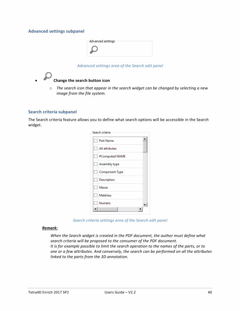
Advanced settings subpanel
Advanced settings area of the Search edit panel
• Change the search button icon
o The search icon that appear in the search widget can be changed by selecting a new image from the file system.
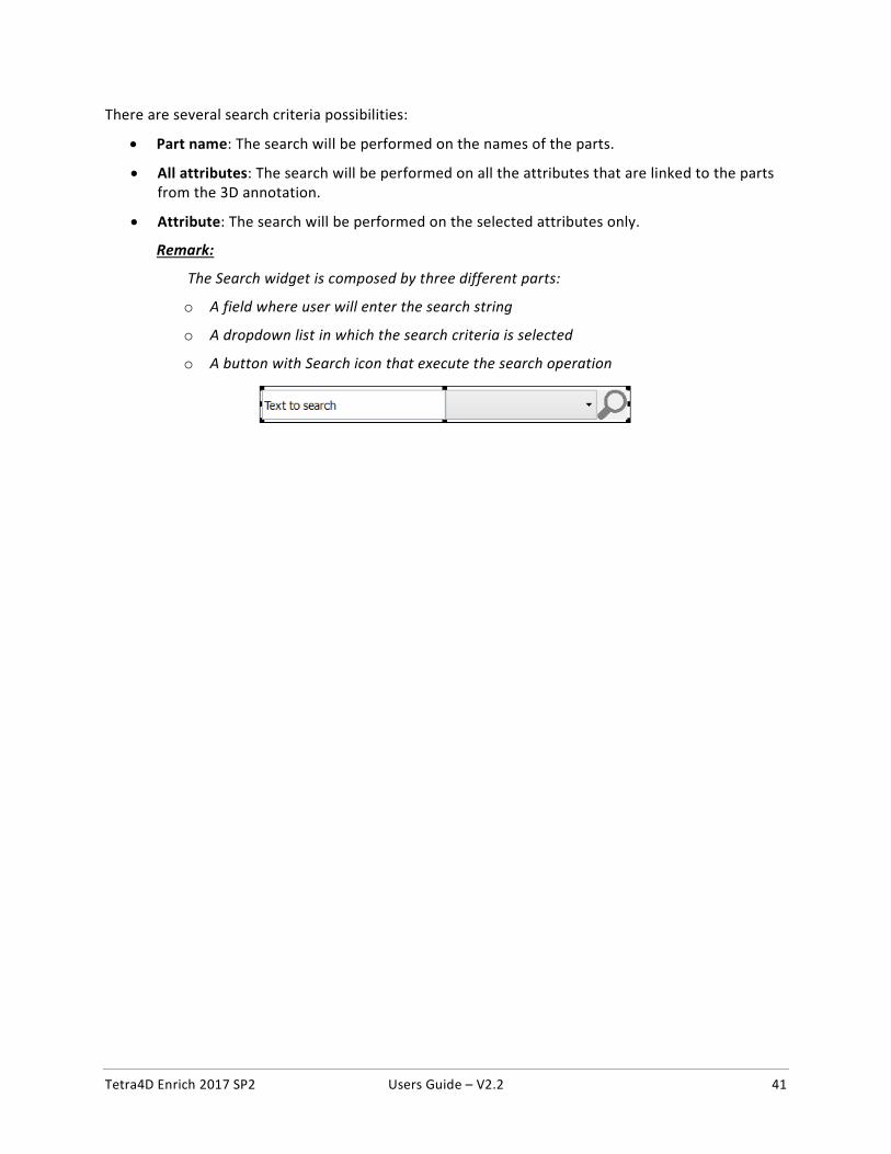
Search criteria subpanel
The Search criteria feature allows you to define what search options will be accessible in the Search widget.
Search criteria settings area of the Search edit panel
Remark:
When the Search widget is created in the PDF document, the author must define what search criteria will be proposed to the consumer of the PDF document. It is for example possible to limit the search operation to the names of the parts, or to one or a few attributes. And conversely, the search can be performed on all the attributes linked to the parts from the 3D annotation.
Tetra4D Enrich 2017 SP2 Users Guide – V2.2 41
There are several search criteria possibilities:
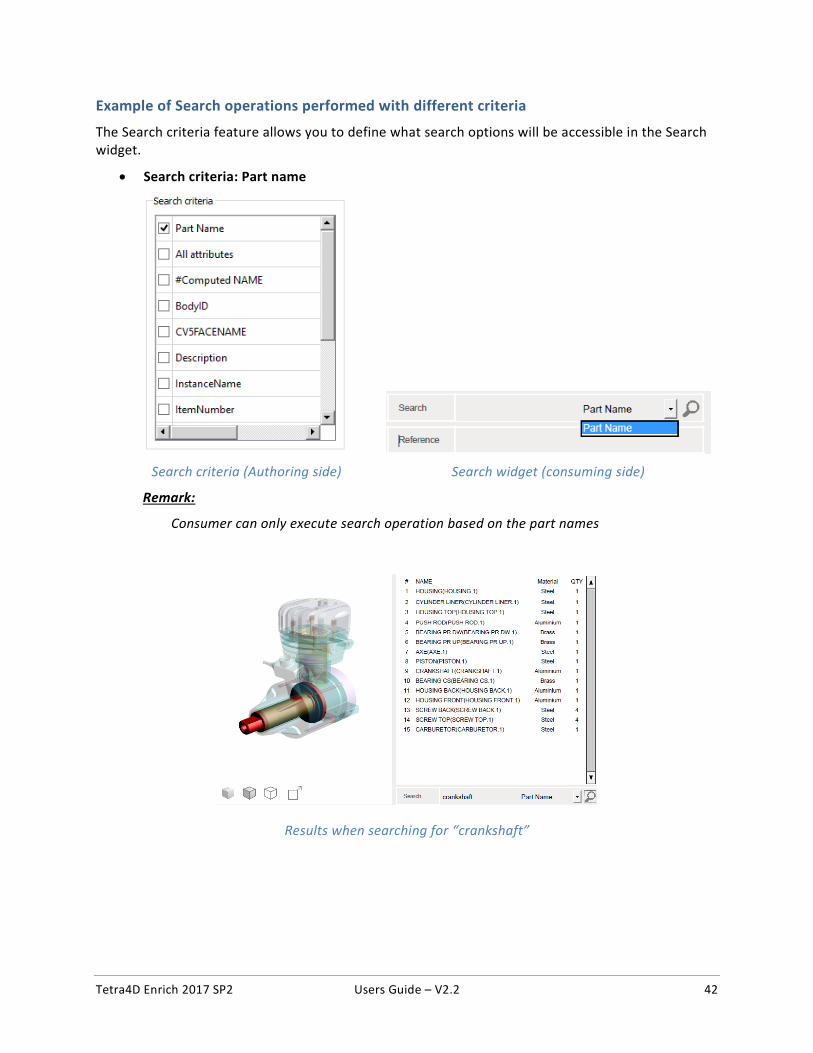
• Part name: The search will be performed on the names of the parts.
• All attributes: The search will be performed on all the attributes that are linked to the parts from the 3D annotation.
• Attribute: The search will be performed on the selected attributes only.
Remark:
The Search widget is composed by three different parts:
o A field where user will enter the search string
o A dropdown list in which the search criteria is selected
o A button with Search icon that execute the search operation
Tetra4D Enrich 2017 SP2 Users Guide – V2.2 42
Example of Search operations performed with different criteria
The Search criteria feature allows you to define what search options will be accessible in the Search widget.
• Search criteria: Part name
Search criteria (Authoring side) Search widget (consuming side)
Remark:
Consumer can only execute search operation based on the part names
Results when searching for “crankshaft”
Tetra4D Enrich 2017 SP2 Users Guide – V2.2 43
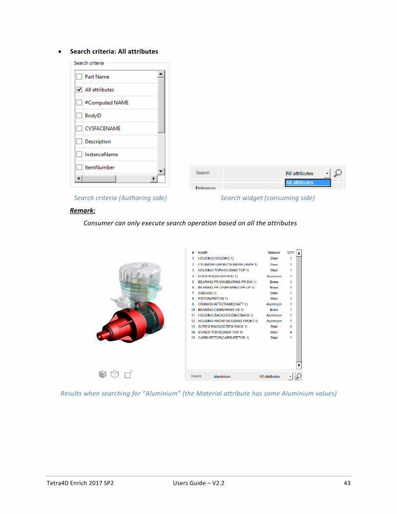
• Search criteria: All attributes
Search criteria (Authoring side) Search widget (consuming side)
Remark:
Consumer can only execute search operation based on all the attributes
Results when searching for “Aluminium” (the Material attribute has some Aluminium values)
Tetra4D Enrich 2017 SP2 Users Guide – V2.2 44
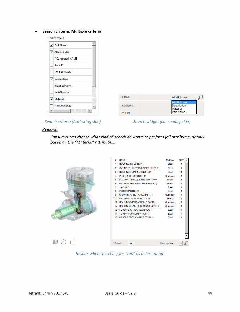
• Search criteria: Multiple criteria
Search criteria (Authoring side) Search widget (consuming side)
Remark:
Consumer can choose what kind of search he wants to perform (all attributes, or only based on the “Material” attribute…)
Results when searching for “rod” as a description
Tetra4D Enrich 2017 SP2 Users Guide – V2.2 45
Actions
The Actions menu allows you to define interactivity between different items within the PDF document, for example:
• Clicking a button will activate a 3D view and will display text in a text field,
• Selecting a part in the 3D annotation (or in the part list) will display several attributes of the part in different text fields…
The actions are defined first by a trigger, and secondly by the operation that will be executed afterwards.
Overview The actions can be triggered by several means:
• On button: the interactivity is triggered by a click on a button.
• On 3D view: the interactivity is triggered by the activation of an existing 3D view.
• On 3D part: the interactivity is triggered by the selection of any part in the 3D annotation.
• On table row: the interactivity is triggered by the selection of a row in a table.
The actions that can be executed afterwards are:
• Activate View: Activates a specified 3D view.
• Previous View: Activates the previous 3D view.
• Next View: Activates the next 3D view.
• Render Mode: Activates a chosen render mode.
• Node Color: Sets a predefined color and transparency to a specified 3D part.
• Node Visibility: Changes the visibility of a selected 3D part.
• Set Text In Field: Outputs text to a text (or a button) field.
• Rotate: Changes the mouse main control (left button) to Rotate mode (which is the default mode).
• Pan: Changes the mouse main control (left button) to Pan mode.
• Zoom: Changes the mouse main control (left button) to Zoom mode.
• Fit Visible: Displays all the visible parts and reset the center of rotation point in the view.
• Fit Selected: Adjusts the zoom in the 3D annotation to fit to a selected 3D part.
• Full Screen Mode: Toggle the display mode of the document to full screen / document modes.
Remark:
This section will first present the different triggers and then all the possible actions.
Tetra4D Enrich 2017 SP2 Users Guide – V2.2 46
Actions > On Button
The actions will be triggered by pressing a button present in the PDF document.
Remark:
The buttons must be defined prior to the creation of the action. Refer to “Add button” for instructions on how to create buttons.
1. Within the Tetra4D Enrich toolbar, choose Action > On Button.
Note: The existing buttons in the active page of the PDF document are highlighted:
• In orange, if no action has been defined on the button, • In green if an action has already been defined.
2. Select the button.
Note: Once selected, the button is highlighted in green.
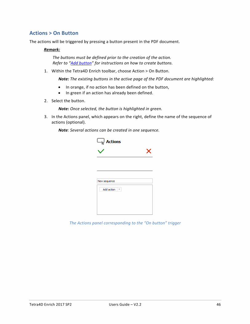
3. In the Actions panel, which appears on the right, define the name of the sequence of actions (optional).
Note: Several actions can be created in one sequence.
The Actions panel corresponding to the “On button” trigger
Tetra4D Enrich 2017 SP2 Users Guide – V2.2 47
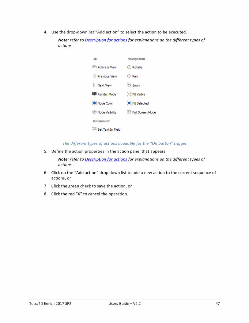
4. Use the drop-down list “Add action” to select the action to be executed.
Note: refer to Description for actions for explanations on the different types of actions.
The different types of actions available for the “On button” trigger
5. Define the action properties in the action panel that appears.
Note: refer to Description for actions for explanations on the different types of actions.
6. Click on the “Add action” drop down list to add a new action to the current sequence of actions, or
7. Click the green check to save the action, or
8. Click the red “X” to cancel the operation.
Tetra4D Enrich 2017 SP2 Users Guide – V2.2 48
Actions > On 3D view
The activation of an existing 3D view can be used to trigger interactivity inside the PDF document. The views must be defined in the 3D annotation prior the creation of the action.
1. Within the Tetra4D Enrich toolbar, choose Action > On 3D view.
2. Select the 3D annotation (if several are present in the active page of the PDF document).
Note: If the active page contains only one 3D annotation, the 3D annotation is automatically selected and highlighted in green.
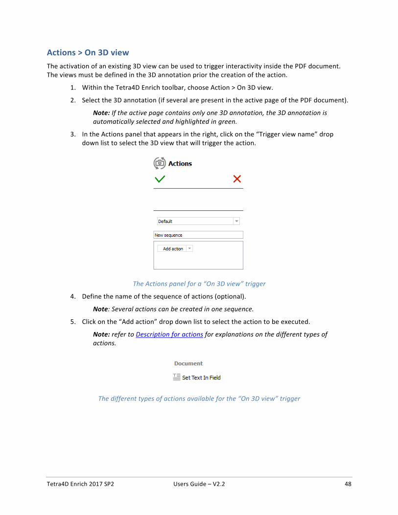
3. In the Actions panel that appears in the right, click on the “Trigger view name” drop down list to select the 3D view that will trigger the action.
The Actions panel for a “On 3D view” trigger
4. Define the name of the sequence of actions (optional).
Note: Several actions can be created in one sequence.
5. Click on the “Add action” drop down list to select the action to be executed.
Note: refer to Description for actions for explanations on the different types of actions.
The different types of actions available for the “On 3D view” trigger

Tetra4D Enrich 2017 SP2 Users Guide – V2.2 49
6. Define the action properties in the action panel that appears.
Note: refer to Description for actions for explanations on the different types of actions.
7. Click on the “Add action” drop down list to add a new action to the current sequence of actions, or
8. Click the green check to save the action, or
9. Click the red “X” to cancel the action.
Tetra4D Enrich 2017 SP2 Users Guide – V2.2 50
Actions > On 3D part
The selection of a part in the 3D annotation or the selection of a row in a part list (flat) or part list (hierarchical) table can be used to trigger interactivity inside the PDF document.
1. Within the Tetra4D Enrich toolbar, choose Action > On 3D part.
2. Select the 3D annotation (if several are present in the active page of the PDF document).
Note: If the active page contains only one 3D annotation, the 3D annotation is automatically selected and highlighted in green.
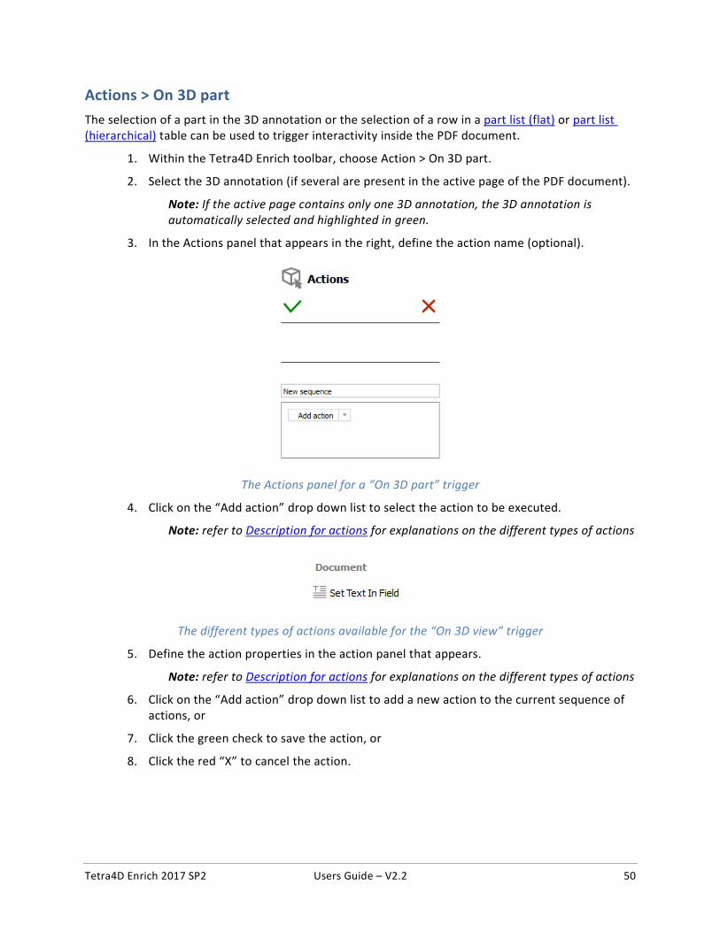
3. In the Actions panel that appears in the right, define the action name (optional).
The Actions panel for a “On 3D part” trigger
4. Click on the “Add action” drop down list to select the action to be executed.
Note: refer to Description for actions for explanations on the different types of actions
The different types of actions available for the “On 3D view” trigger
5. Define the action properties in the action panel that appears.
Note: refer to Description for actions for explanations on the different types of actions
6. Click on the “Add action” drop down list to add a new action to the current sequence of actions, or
7. Click the green check to save the action, or
8. Click the red “X” to cancel the action.
Tetra4D Enrich 2017 SP2 Users Guide – V2.2 51
Actions > On table row
The selection of a row in a table can be used to trigger interactivity inside the PDF document.
1. Within the Tetra4D Enrich toolbar, choose Action > On table row
2. Select the row in the table
Note: The table is highlighted in orange before selection.
When clicking a table, the row is selected and highlighted in green.
If needed, it is possible to click another row from the same table.
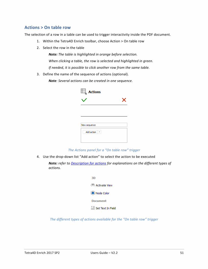
3. Define the name of the sequence of actions (optional).
Note: Several actions can be created in one sequence.
The Actions panel for a “On table row” trigger
4. Use the drop-down list “Add action” to select the action to be executed
Note: refer to Description for actions for explanations on the different types of actions.
The different types of actions available for the “On table row” trigger

Tetra4D Enrich 2017 SP2 Users Guide – V2.2 52
5. Define the action properties in the action panel that appears.
Note: refer to Description for actions for explanations on the different types of actions.
6. Click on the “Add action” drop down list to add a new action to the current sequence of actions, or
7. Click the green check to save the action, or
8. Click the red “X” to cancel the action.
Tetra4D Enrich 2017 SP2 Users Guide – V2.2 53
Description of actions
This section presents the different types of actions and their related parameters.
Refer to “Actions” for explanations on how to trigger the actions.
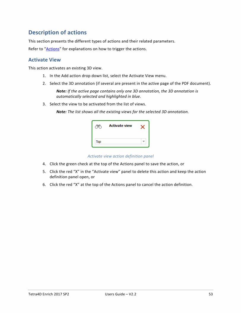
Activate View This action activates an existing 3D view.
1. In the Add action drop down list, select the Activate View menu.
2. Select the 3D annotation (if several are present in the active page of the PDF document).
Note: If the active page contains only one 3D annotation, the 3D annotation is automatically selected and highlighted in blue.
3. Select the view to be activated from the list of views.
Note: The list shows all the existing views for the selected 3D annotation.
Activate view action definition panel
4. Click the green check at the top of the Actions panel to save the action, or
5. Click the red “X” in the “Activate view” panel to delete this action and keep the action definition panel open, or
6. Click the red “X” at the top of the Actions panel to cancel the action definition.
Tetra4D Enrich 2017 SP2 Users Guide – V2.2 54
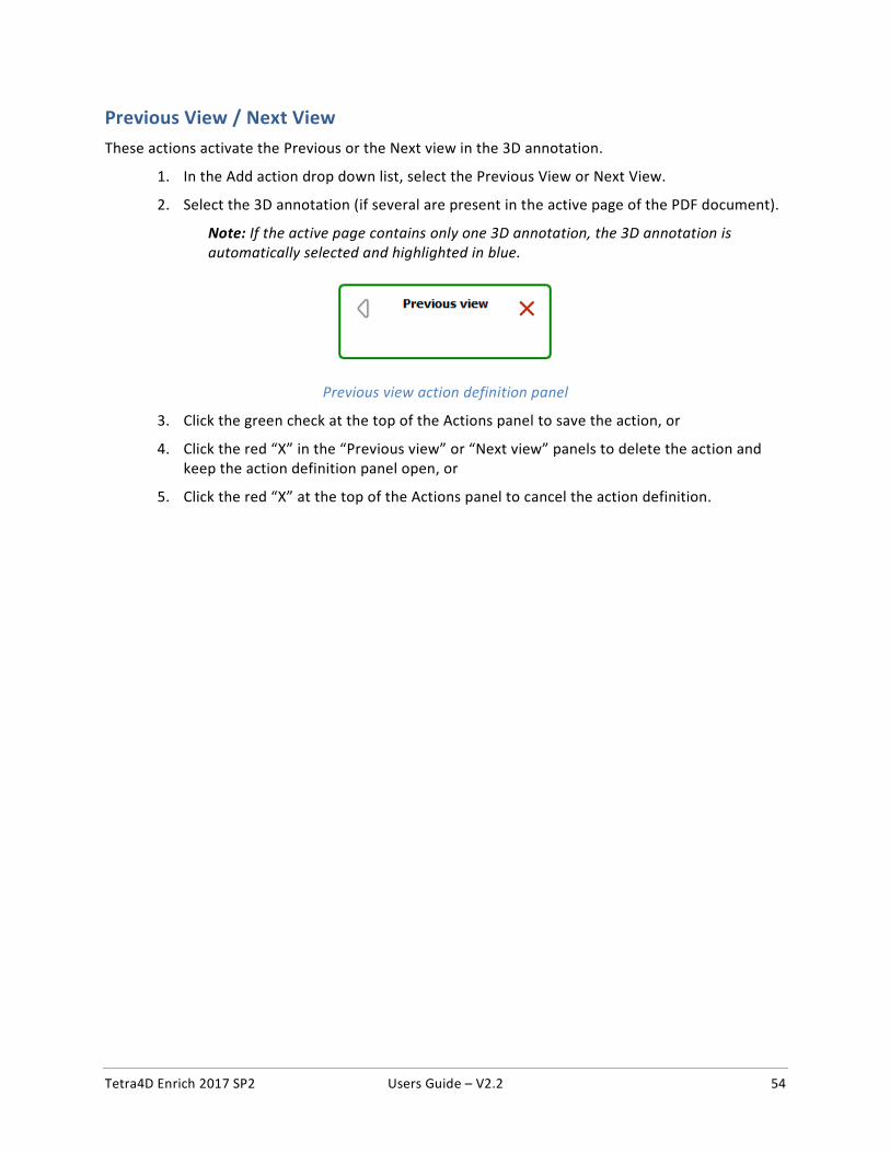
Previous View / Next View These actions activate the Previous or the Next view in the 3D annotation.
1. In the Add action drop down list, select the Previous View or Next View.
2. Select the 3D annotation (if several are present in the active page of the PDF document).
Note: If the active page contains only one 3D annotation, the 3D annotation is automatically selected and highlighted in blue.
Previous view action definition panel
3. Click the green check at the top of the Actions panel to save the action, or
4. Click the red “X” in the “Previous view” or “Next view” panels to delete the action and keep the action definition panel open, or
5. Click the red “X” at the top of the Actions panel to cancel the action definition.
Tetra4D Enrich 2017 SP2 Users Guide – V2.2 55
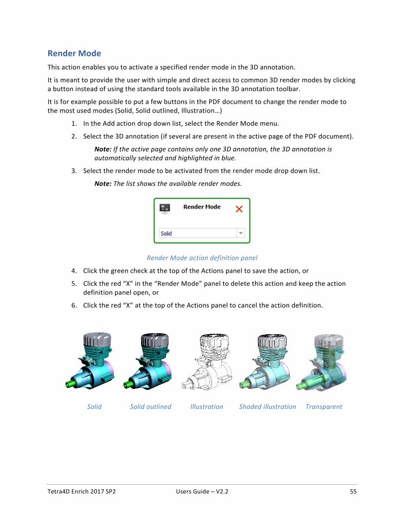
Render Mode This action enables you to activate a specified render mode in the 3D annotation.
It is meant to provide the user with simple and direct access to common 3D render modes by clicking a button instead of using the standard tools available in the 3D annotation toolbar.
It is for example possible to put a few buttons in the PDF document to change the render mode to the most used modes (Solid, Solid outlined, Illustration…)
1. In the Add action drop down list, select the Render Mode menu.
2. Select the 3D annotation (if several are present in the active page of the PDF document).
Note: If the active page contains only one 3D annotation, the 3D annotation is automatically selected and highlighted in blue.
3. Select the render mode to be activated from the render mode drop down list.
Note: The list shows the available render modes.
Render Mode action definition panel
4. Click the green check at the top of the Actions panel to save the action, or
5. Click the red “X” in the “Render Mode” panel to delete this action and keep the action definition panel open, or
6. Click the red “X” at the top of the Actions panel to cancel the action definition.
Solid Solid outlined Illustration Shaded illustration Transparent
Tetra4D Enrich 2017 SP2 Users Guide – V2.2 56
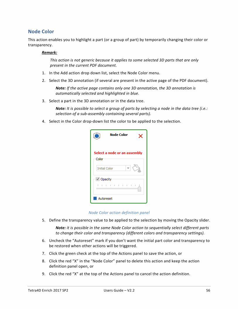
Node Color This action enables you to highlight a part (or a group of part) by temporarily changing their color or transparency.
Remark:
This action is not generic because it applies to some selected 3D parts that are only present in the current PDF document.
1. In the Add action drop down list, select the Node Color menu.
2. Select the 3D annotation (if several are present in the active page of the PDF document).
Note: If the active page contains only one 3D annotation, the 3D annotation is automatically selected and highlighted in blue.
3. Select a part in the 3D annotation or in the data tree.
Note: It is possible to select a group of parts by selecting a node in the data tree (i.e.: selection of a sub-assembly containing several parts).
4. Select in the Color drop-down list the color to be applied to the selection.
Node Color action definition panel
5. Define the transparency value to be applied to the selection by moving the Opacity slider.
Note: it is possible in the same Node Color action to sequentially select different parts to change their color and transparency (different colors and transparency settings).
6. Uncheck the “Autoreset” mark if you don’t want the initial part color and transparency to be restored when other actions will be triggered.
7. Click the green check at the top of the Actions panel to save the action, or
8. Click the red “X” in the “Node Color” panel to delete this action and keep the action definition panel open, or
9. Click the red “X” at the top of the Actions panel to cancel the action definition.
Tetra4D Enrich 2017 SP2 Users Guide – V2.2 57
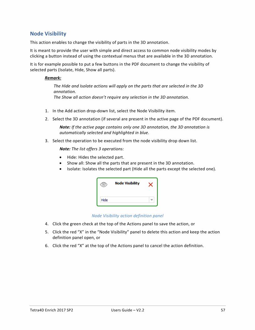
Node Visibility This action enables to change the visibility of parts in the 3D annotation.
It is meant to provide the user with simple and direct access to common node visibility modes by clicking a button instead of using the contextual menus that are available in the 3D annotation.
It is for example possible to put a few buttons in the PDF document to change the visibility of selected parts (Isolate, Hide, Show all parts).
Remark:
The Hide and Isolate actions will apply on the parts that are selected in the 3D annotation. The Show all action doesn’t require any selection in the 3D annotation.
1. In the Add action drop-down list, select the Node Visibility item.
2. Select the 3D annotation (if several are present in the active page of the PDF document).
Note: If the active page contains only one 3D annotation, the 3D annotation is automatically selected and highlighted in blue.
3. Select the operation to be executed from the node visibility drop down list.
Note: The list offers 3 operations:
• Hide: Hides the selected part. • Show all: Show all the parts that are present in the 3D annotation. • Isolate: Isolates the selected part (Hide all the parts except the selected one).
Node Visibility action definition panel
4. Click the green check at the top of the Actions panel to save the action, or
5. Click the red “X” in the “Node Visibility” panel to delete this action and keep the action definition panel open, or
6. Click the red “X” at the top of the Actions panel to cancel the action definition.
Tetra4D Enrich 2017 SP2 Users Guide – V2.2 58
Set Text in Field This action enables you to output a text in a text field or in a button.
Remark:
The text fields must be defined prior the creation of the action. Refer to “Add text field” for instructions on how to create text fields.
Remark:
When triggered by an “On button”, “On 3D view”, or an “On table row” event, the “Set text In Field” action enables output of predefined text (static) in a text field. When triggered by a “On 3D part” event (selection of a part in the 3D annotation), the “Set text In Field” action can write static text or information about the selected part (CAD attributes or imported attributes) to a text field.
1. In the Add action drop down list, select the Set Text in Field menu.
2. Select a text field or a button (where the text will be displayed).
Note: All the buttons and text fields from the active page are highlighted in orange.
Once selected, the text field or the button is highlighted in blue.
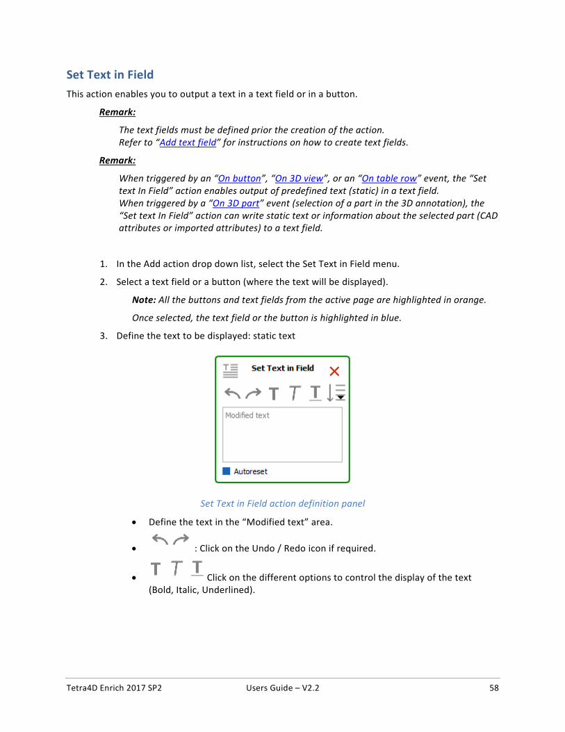
3. Define the text to be displayed: static text
Set Text in Field action definition panel
• Define the text in the “Modified text” area.
• : Click on the Undo / Redo icon if required.
• Click on the different options to control the display of the text (Bold, Italic, Underlined).

Tetra4D Enrich 2017 SP2 Users Guide – V2.2 59
4. Or define the 3D part attribute to be displayed in the text field:
• : Click on the “Add selected Attribute into the text area.” • Select the attribute in the list of attributes.
List of existing attributes
Note: After its selection in the list of available attributes, the attribute is identified in the text definition area as follows:
Set Text in Field action definition panel showing an attribute linked to the CAD part
5. Uncheck the “Autoreset” mark if you don’t want the text field being restored (emptied) when other actions will be triggered.
6. Click the green check at the top of the Actions panel to save the action, or
7. Click the red “X” in the “Set Text in Field” panel to delete this action and keep the action definition panel open, or
8. Click the red “X” at the top of the Actions panel to cancel the action definition.
Tetra4D Enrich 2017 SP2 Users Guide – V2.2 60
Rotate / Pan / Zoon These actions enable users to change the 3D operation accessed by using the left mouse button.
It is meant to provide the user with simple and direct access to the main 3D operations which control the display of the model (rotation of the 3D, Pan, zoom in and out).
It is for example possible to define buttons in the PDF document to give to the user access to these three operations by clicking the buttons, instead of using the standard 3D toolbar or 3D controls accessible through the left and right mouse buttons.
Remark:
These actions are directly executed and don’t require any selection in the 3D annotation.
1. In the Add action drop down list, select the Rotate (or Pan or Zoom) menu.
2. Select the 3D annotation (if several are present in the active page of the PDF document).
Note: If the active page contains only one 3D annotation, the 3D annotation is automatically selected and highlighted in blue.
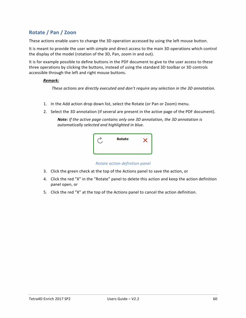
Rotate action definition panel
3. Click the green check at the top of the Actions panel to save the action, or
4. Click the red “X” in the “Rotate” panel to delete this action and keep the action definition panel open, or
5. Click the red “X” at the top of the Actions panel to cancel the action definition.
Tetra4D Enrich 2017 SP2 Users Guide – V2.2 61
Fit visible This action enables users to execute a Fit Visible operation in the 3D annotation.
This action is meant to provide users with simple and direct access to the Fit Visible operation to adjust the zoom so that all the currently visible parts will be visible in the 3D annotation and will also reset the center rotation point of the part/model.
It is for example possible to define a button in the PDF document to give to the user access to this Fit Visible operation by clicking the button, instead of using the standard 3D toolbar or the contextual menus that are available in the 3D annotation.
Remark:
This action is directly executed and doesn’t require any selection in the 3D annotation.
1. In the Add action drop down list, select the Fit Visible menu.
2. Select the 3D annotation (if several are present in the active page of the PDF document).
Note: If the active page contains only one 3D annotation, the 3D annotation is automatically selected and highlighted in blue.
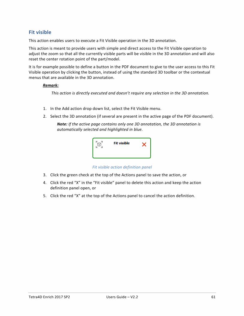
Fit visible action definition panel
3. Click the green check at the top of the Actions panel to save the action, or
4. Click the red “X” in the “Fit visible” panel to delete this action and keep the action definition panel open, or
5. Click the red “X” at the top of the Actions panel to cancel the action definition.
Tetra4D Enrich 2017 SP2 Users Guide – V2.2 62
Fit selected This action enables to execute a Fit Selected operation in the 3D annotation.
This action is meant to provide users with simple and direct access to the Fit Selected operation so that the zoom will be adjusted to make the selected part fit to the 3D annotation.
It is for example possible to define a button in the PDF document to give to the user access to this Fit Selected operation instead of using the contextual menus that are available in the 3D annotation.
Remark:
This action requires a part to be selected in the 3D annotation.
1. In the Add action drop down list, select the Fit Selected menu.
2. Select the 3D annotation (if several are present in the active page of the PDF document).
Note: If the active page contains only one 3D annotation, the 3D annotation is automatically selected and highlighted in blue.
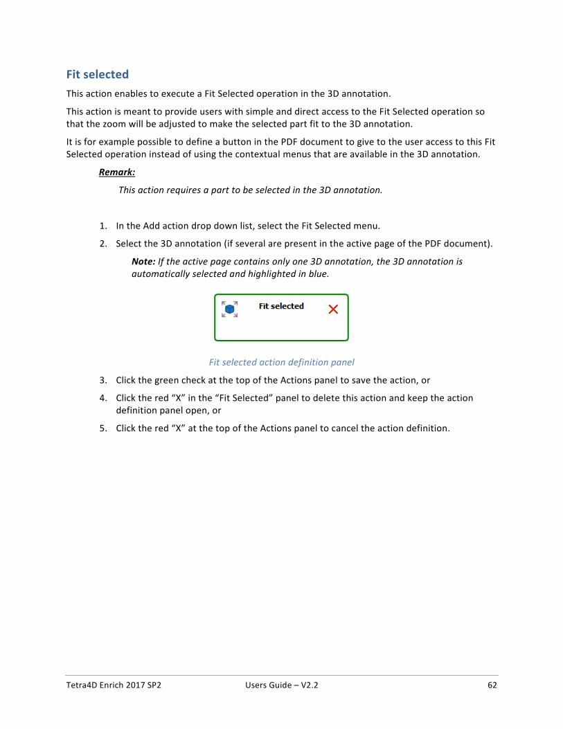
Fit selected action definition panel
3. Click the green check at the top of the Actions panel to save the action, or
4. Click the red “X” in the “Fit Selected” panel to delete this action and keep the action definition panel open, or
5. Click the red “X” at the top of the Actions panel to cancel the action definition.
Tetra4D Enrich 2017 SP2 Users Guide – V2.2 63
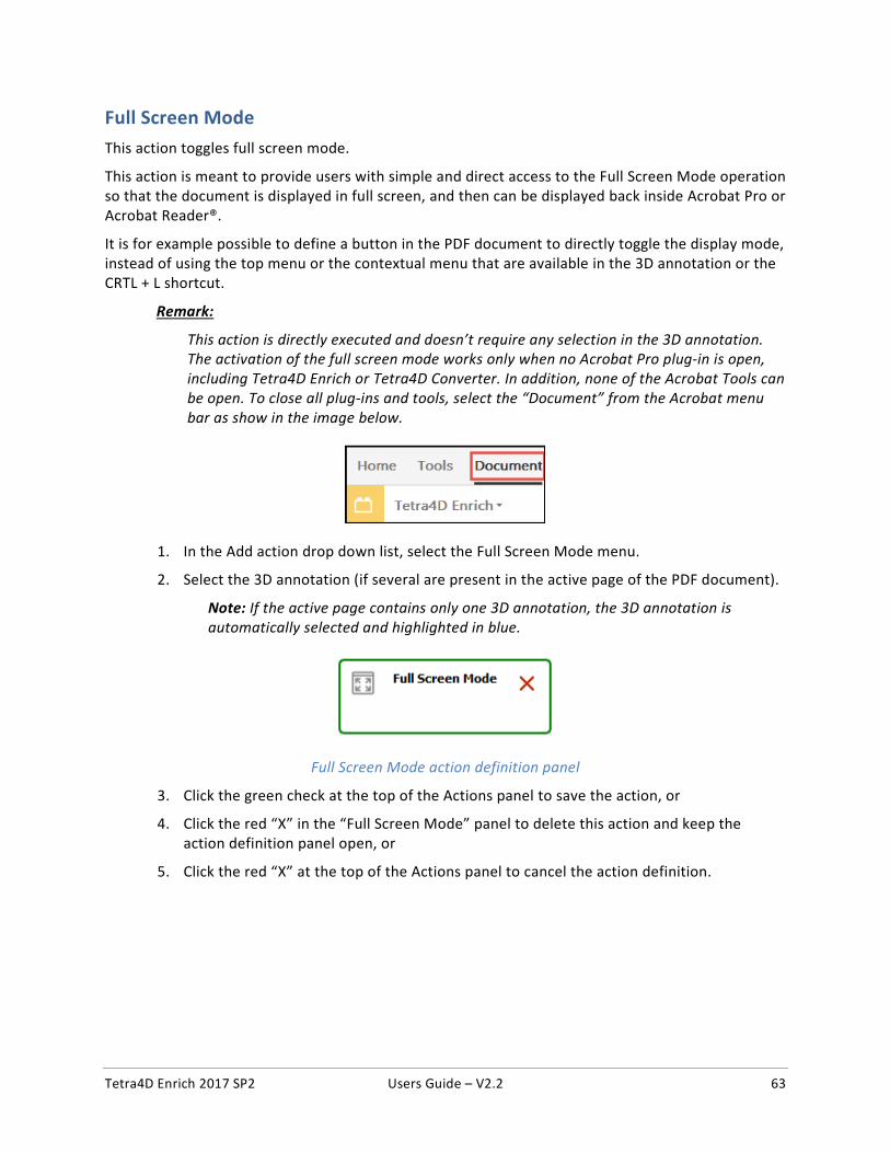
Full Screen Mode This action toggles full screen mode.
This action is meant to provide users with simple and direct access to the Full Screen Mode operation so that the document is displayed in full screen, and then can be displayed back inside Acrobat Pro or Acrobat Reader®.
It is for example possible to define a button in the PDF document to directly toggle the display mode, instead of using the top menu or the contextual menu that are available in the 3D annotation or the CRTL + L shortcut.
Remark:
This action is directly executed and doesn’t require any selection in the 3D annotation. The activation of the full screen mode works only when no Acrobat Pro plug-in is open, including Tetra4D Enrich or Tetra4D Converter. In addition, none of the Acrobat Tools can be open. To close all plug-ins and tools, select the “Document” from the Acrobat menu bar as show in the image below.
1. In the Add action drop down list, select the Full Screen Mode menu.
2. Select the 3D annotation (if several are present in the active page of the PDF document).
Note: If the active page contains only one 3D annotation, the 3D annotation is automatically selected and highlighted in blue.
Full Screen Mode action definition panel
3. Click the green check at the top of the Actions panel to save the action, or
4. Click the red “X” in the “Full Screen Mode” panel to delete this action and keep the action definition panel open, or
5. Click the red “X” at the top of the Actions panel to cancel the action definition.
Tetra4D Enrich 2017 SP2 Users Guide – V2.2 64
Edit
The Edit feature makes it possible to:
• Modify the content of the 3D annotation:
o visibility of parts,
o position of parts.
• Edit the existing Tetra4D Enrich widgets (Table, Carousel of views, Search)
• Edit the existing Tetra4D actions.
Edit 3D
This section shows a detailed explanation about the possible modifications of the 3D annotation.
1. Within the Tetra4D Enrich toolbar, choose Edit 3D.
2. In the Edit 3D panel, check the “Multiple selection” mark to toggle the parts selection mode between the standard Adobe Acrobat one and the Tetra4D Enrich “multiple selection” mode.
Note: Refer to “Edit 3D: Selection modes” to have detailed explanations about the selection feature provided by Edit 3D.
3. Use the selection features to control or modify the current selection.
4. Change the visibility of parts with the Visibility check mark, or
Note: Refer to “Edit 3D: Control of part visibility” to have detailed explanations about the status check behavior.
5. Check the mark “Activate transform feature” to enable the transform feature, and use the handler to move the selected parts.
Note: Refer to “Edit 3D: Transform feature” to have detailed explanations about the transform feature.
6. Click on the green check to accept the modification and close the function.
Tetra4D Enrich 2017 SP2 Users Guide – V2.2 65
Edit 3D: Selection modes The Edit 3D feature provides the ability to select several parts at the same time to ease and shorten the process of creating views when the visibility and/or the positions of parts must be changed.
Remark:
The selection mode of Adobe Acrobat makes it possible to select a single part or a group of parts if they all belong to the same hierarchical level of an assembly, but doesn’t provide the ability to select simultaneously any parts from one assembly.
1. Check the Multiple selection mark to enable the multiple selection mode
2. Select in the 3D annotation the part to be added to the selection
Note: The selected parts are highlighted in blue.
3. Add a part to the selection set by selecting it in the 3D annotation
Note: It is not required to press the CTRL Key to add a part to the selection.
4. Click again an already selected part to unselect it
5. Select one the available feature (Visibility status or Transform), or
Note: See below for details about selection features.
6. Select one the Selection option to modify the selection set, or
7. Click into the 3D annotation to unselect all the parts
Remark:
When working with the Edit 3D feature, it is recommended not to select parts in the data tree because the multiple selection mechanism is designed for 3D selection of parts, and because it overrides the Adobe Acrobat standard selection feature (even when the multiple selection is not active).
Remark:
It is possible to switch between the standard Adobe Acrobat selection mode and the multiple selection mode during one selection sequence.
Tetra4D Enrich 2017 SP2 Users Guide – V2.2 66
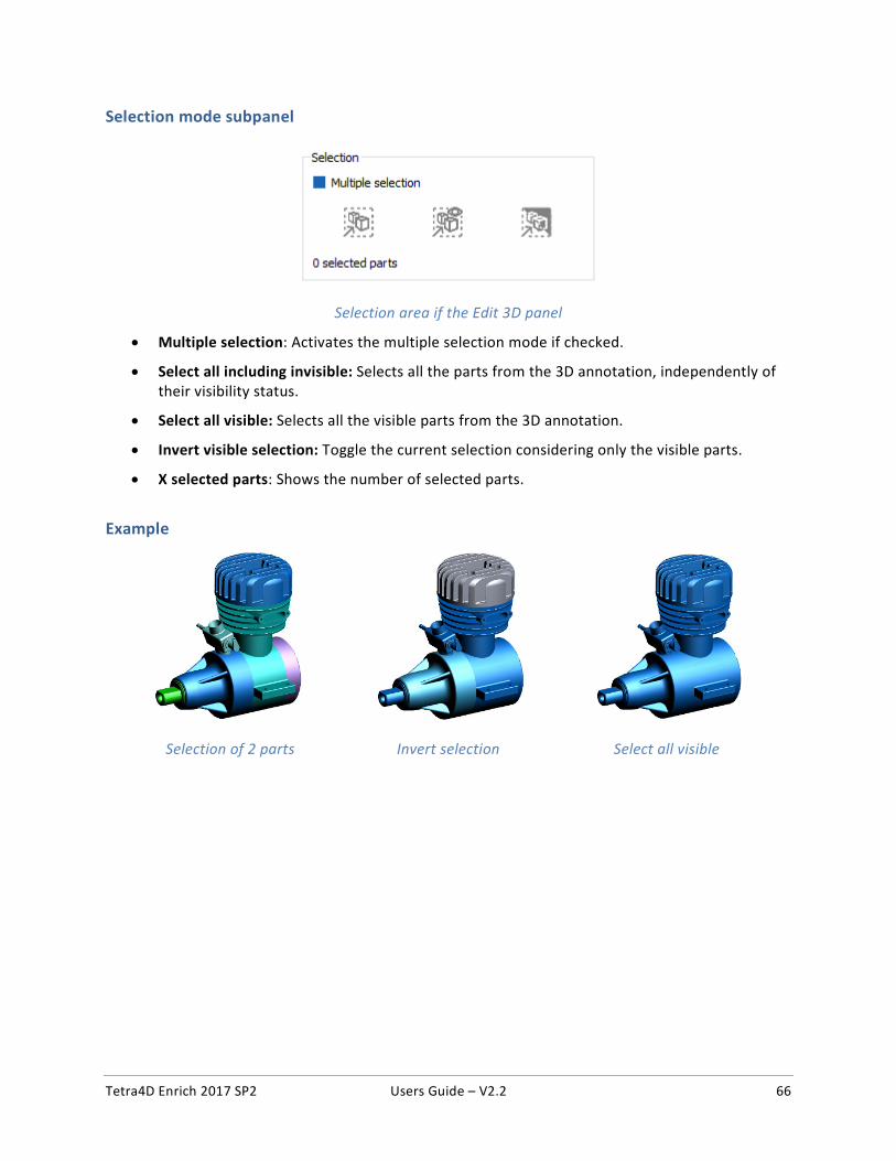
Selection mode subpanel
Selection area if the Edit 3D panel
• Multiple selection: Activates the multiple selection mode if checked.
• Select all including invisible: Selects all the parts from the 3D annotation, independently of their visibility status.
• Select all visible: Selects all the visible parts from the 3D annotation.
• Invert visible selection: Toggle the current selection considering only the visible parts.
• X selected parts: Shows the number of selected parts.
Example
Selection of 2 parts Invert selection Select all visible
Tetra4D Enrich 2017 SP2 Users Guide – V2.2 67
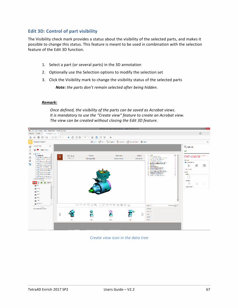
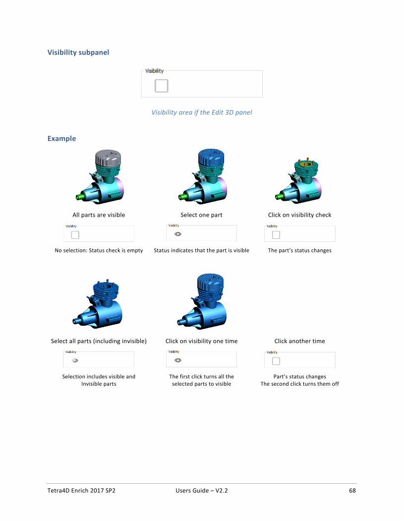
Edit 3D: Control of part visibility The Visibility check mark provides a status about the visibility of the selected parts, and makes it possible to change this status. This feature is meant to be used in combination with the selection feature of the Edit 3D function.
1. Select a part (or several parts) in the 3D annotation
2. Optionally use the Selection options to modify the selection set
3. Click the Visibility mark to change the visibility status of the selected parts
Note: the parts don’t remain selected after being hidden.
Remark:
Once defined, the visibility of the parts can be saved as Acrobat views. It is mandatory to use the “Create view” feature to create an Acrobat view. The view can be created without closing the Edit 3D feature.
Create view icon in the data tree
Tetra4D Enrich 2017 SP2 Users Guide – V2.2 68
Visibility subpanel
Visibility area if the Edit 3D panel
Example
All parts are visible Select one part Click on visibility check
No selection: Status check is empty Status indicates that the part is visible The part’s status changes
Select all parts (including invisible) Click on visibility one time Click another time
Selection includes visible and The first click turns all the Part’s status changes Invisible parts selected parts to visible The second click turns them off
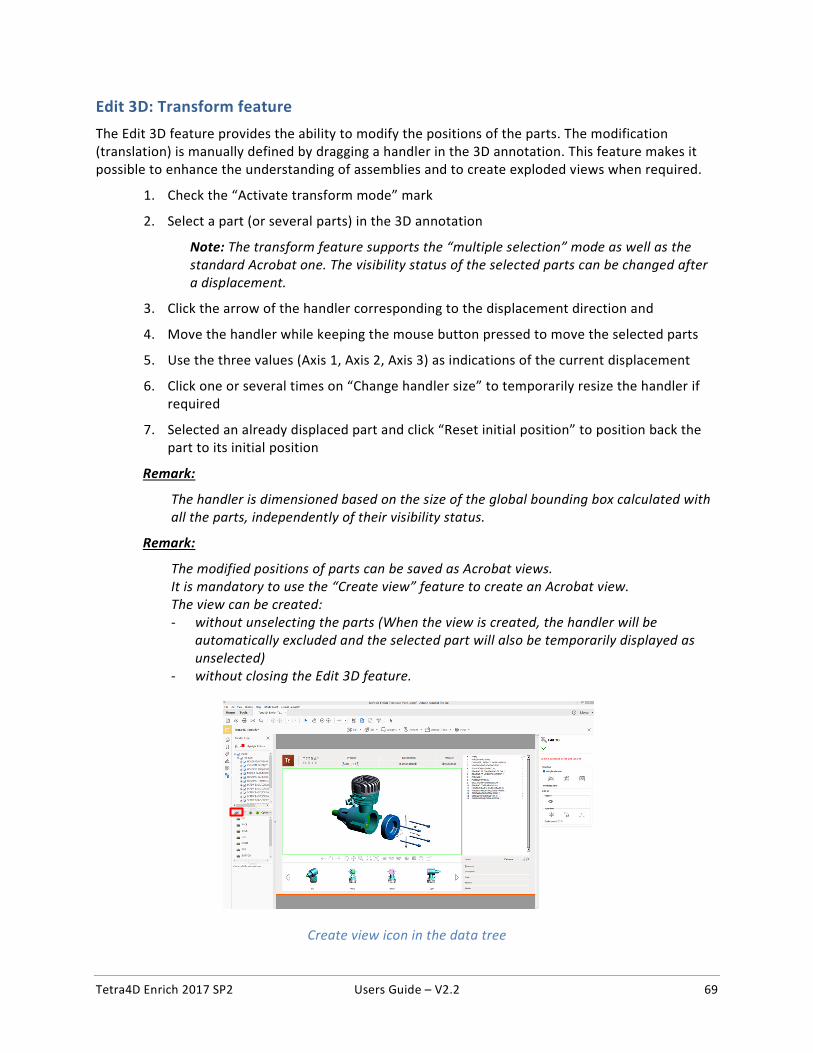
Tetra4D Enrich 2017 SP2 Users Guide – V2.2 69
Edit 3D: Transform feature The Edit 3D feature provides the ability to modify the positions of the parts. The modification (translation) is manually defined by dragging a handler in the 3D annotation. This feature makes it possible to enhance the understanding of assemblies and to create exploded views when required.
1. Check the “Activate transform mode” mark
2. Select a part (or several parts) in the 3D annotation
Note: The transform feature supports the “multiple selection” mode as well as the standard Acrobat one. The visibility status of the selected parts can be changed after a displacement.
3. Click the arrow of the handler corresponding to the displacement direction and
4. Move the handler while keeping the mouse button pressed to move the selected parts
5. Use the three values (Axis 1, Axis 2, Axis 3) as indications of the current displacement
6. Click one or several times on “Change handler size” to temporarily resize the handler if required
7. Selected an already displaced part and click “Reset initial position” to position back the part to its initial position
Remark:
The handler is dimensioned based on the size of the global bounding box calculated with all the parts, independently of their visibility status.
Remark:
The modified positions of parts can be saved as Acrobat views. It is mandatory to use the “Create view” feature to create an Acrobat view. The view can be created: - without unselecting the parts (When the view is created, the handler will be
automatically excluded and the selected part will also be temporarily displayed as unselected)
- without closing the Edit 3D feature.
Create view icon in the data tree
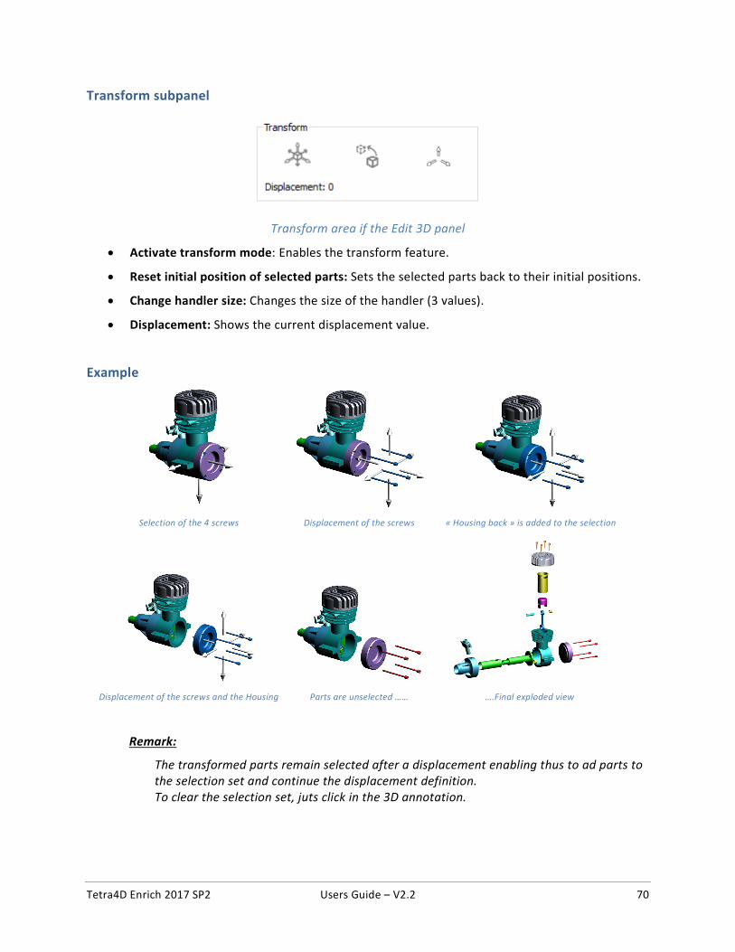
Tetra4D Enrich 2017 SP2 Users Guide – V2.2 70
Transform subpanel
Transform area if the Edit 3D panel
• Activate transform mode: Enables the transform feature.
• Reset initial position of selected parts: Sets the selected parts back to their initial positions.
• Change handler size: Changes the size of the handler (3 values).
• Displacement: Shows the current displacement value.
Example
Selection of the 4 screws Displacement of the screws « Housing back » is added to the selection
Displacement of the screws and the Housing Parts are unselected …… ….Final exploded view
Remark:
The transformed parts remain selected after a displacement enabling thus to ad parts to the selection set and continue the displacement definition. To clear the selection set, juts click in the 3D annotation.
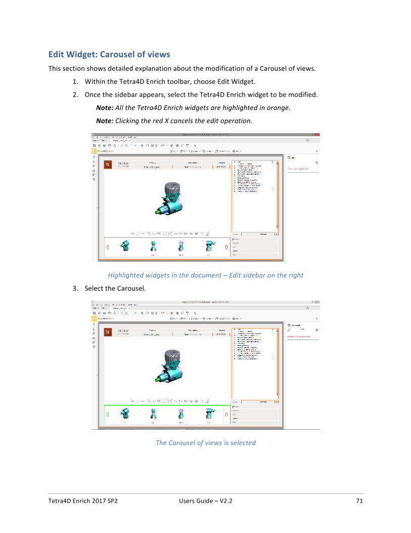
Tetra4D Enrich 2017 SP2 Users Guide – V2.2 71
Edit Widget: Carousel of views
This section shows detailed explanation about the modification of a Carousel of views.
1. Within the Tetra4D Enrich toolbar, choose Edit Widget.
2. Once the sidebar appears, select the Tetra4D Enrich widget to be modified.
Note: All the Tetra4D Enrich widgets are highlighted in orange.
Note: Clicking the red X cancels the edit operation.
Highlighted widgets in the document – Edit sidebar on the right
3. Select the Carousel.
The Carousel of views is selected
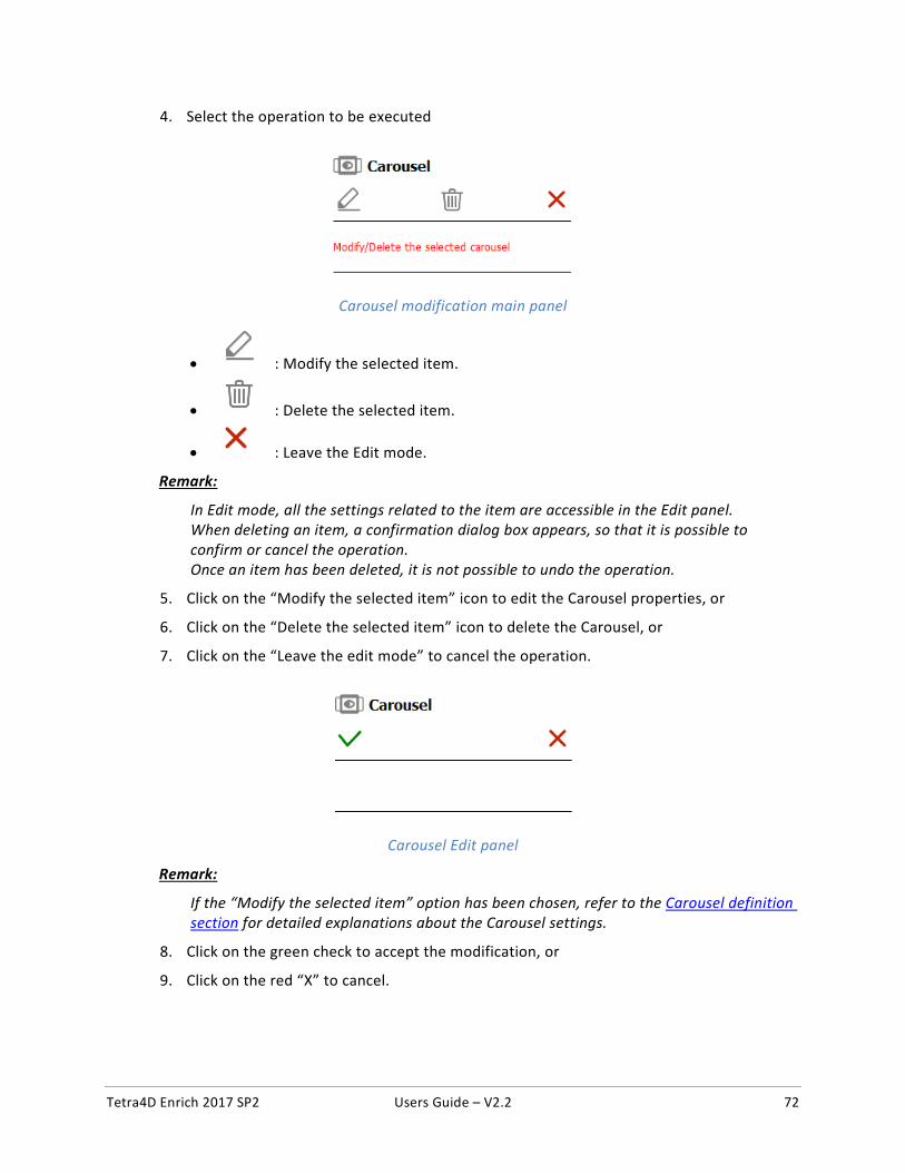
Tetra4D Enrich 2017 SP2 Users Guide – V2.2 72
4. Select the operation to be executed
Carousel modification main panel
• : Modify the selected item.
• : Delete the selected item.
• : Leave the Edit mode.
Remark:
In Edit mode, all the settings related to the item are accessible in the Edit panel. When deleting an item, a confirmation dialog box appears, so that it is possible to confirm or cancel the operation. Once an item has been deleted, it is not possible to undo the operation.
5. Click on the “Modify the selected item” icon to edit the Carousel properties, or
6. Click on the “Delete the selected item” icon to delete the Carousel, or
7. Click on the “Leave the edit mode” to cancel the operation.
Carousel Edit panel
Remark:
If the “Modify the selected item” option has been chosen, refer to the Carousel definition section for detailed explanations about the Carousel settings.
8. Click on the green check to accept the modification, or
9. Click on the red “X” to cancel.
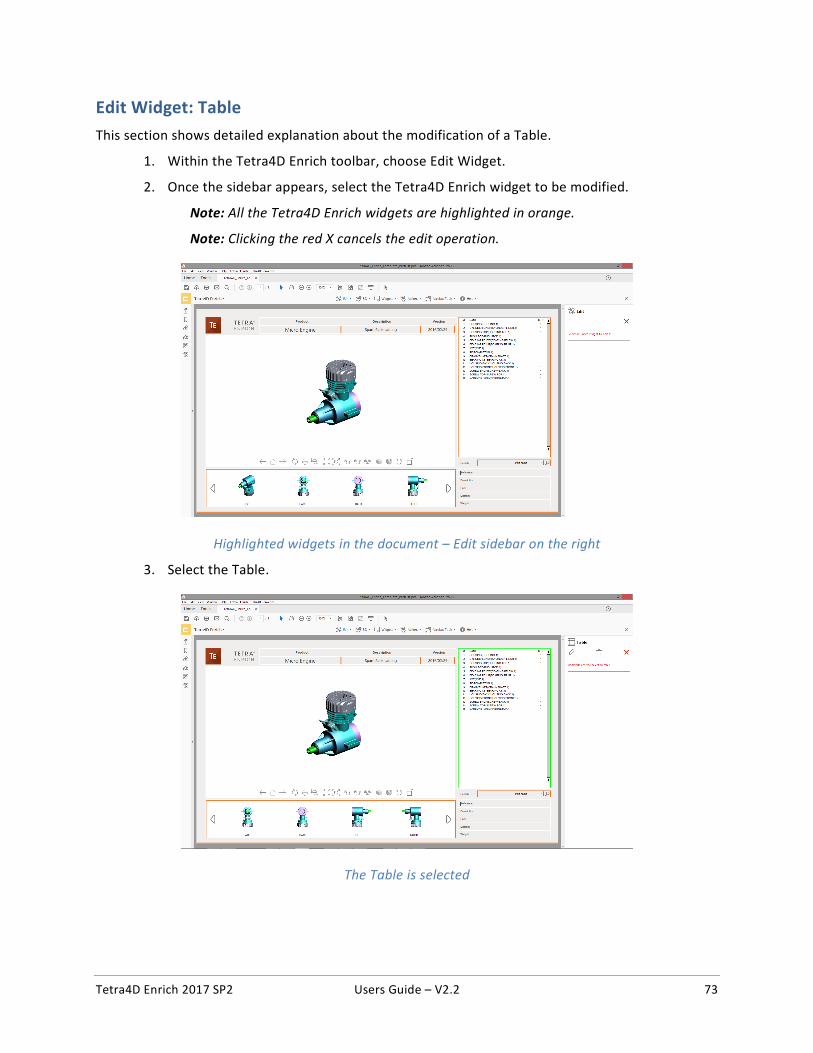
Tetra4D Enrich 2017 SP2 Users Guide – V2.2 73
Edit Widget: Table
This section shows detailed explanation about the modification of a Table.
1. Within the Tetra4D Enrich toolbar, choose Edit Widget.
2. Once the sidebar appears, select the Tetra4D Enrich widget to be modified.
Note: All the Tetra4D Enrich widgets are highlighted in orange.
Note: Clicking the red X cancels the edit operation.
Highlighted widgets in the document – Edit sidebar on the right
3. Select the Table.
The Table is selected
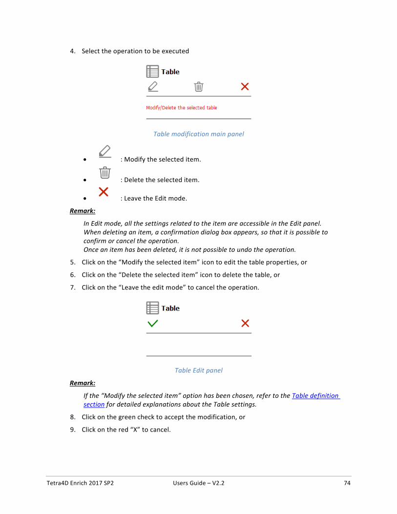
Tetra4D Enrich 2017 SP2 Users Guide – V2.2 74
4. Select the operation to be executed
Table modification main panel
• : Modify the selected item.
• : Delete the selected item.
• : Leave the Edit mode.
Remark:
In Edit mode, all the settings related to the item are accessible in the Edit panel. When deleting an item, a confirmation dialog box appears, so that it is possible to confirm or cancel the operation. Once an item has been deleted, it is not possible to undo the operation.
5. Click on the “Modify the selected item” icon to edit the table properties, or
6. Click on the “Delete the selected item” icon to delete the table, or
7. Click on the “Leave the edit mode” to cancel the operation.
Table Edit panel
Remark:
If the “Modify the selected item” option has been chosen, refer to the Table definition section for detailed explanations about the Table settings.
8. Click on the green check to accept the modification, or
9. Click on the red “X” to cancel.
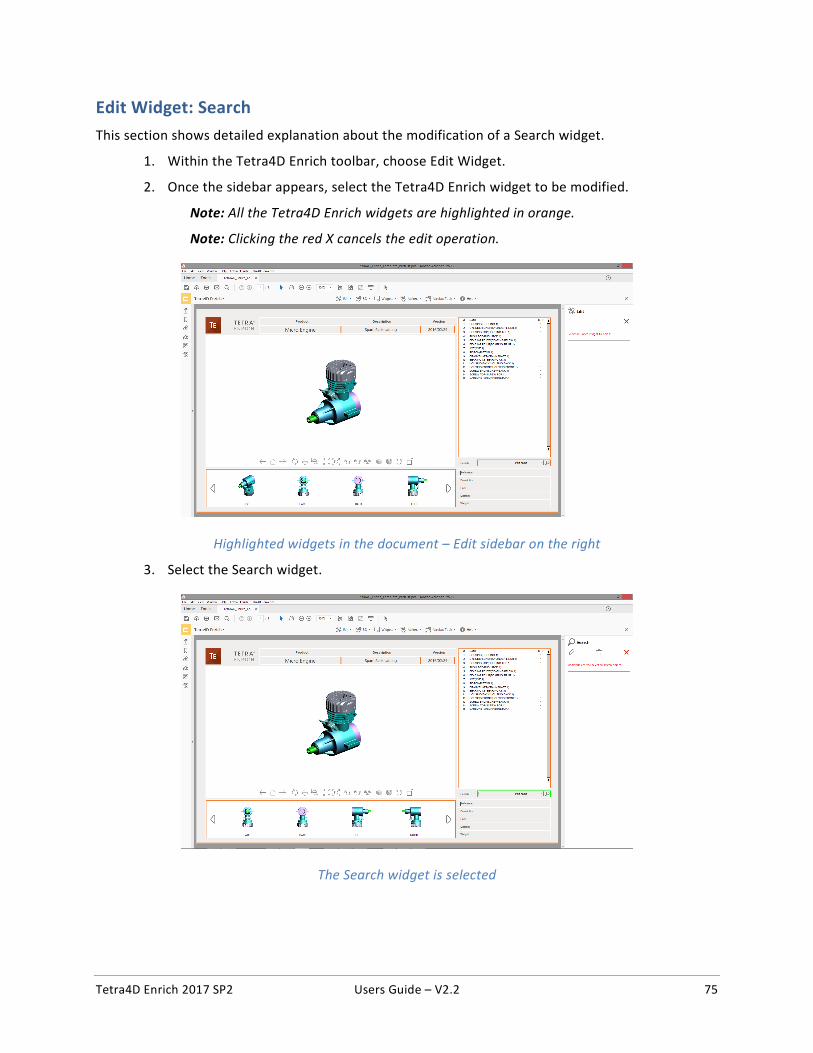
Tetra4D Enrich 2017 SP2 Users Guide – V2.2 75
Edit Widget: Search
This section shows detailed explanation about the modification of a Search widget.
1. Within the Tetra4D Enrich toolbar, choose Edit Widget.
2. Once the sidebar appears, select the Tetra4D Enrich widget to be modified.
Note: All the Tetra4D Enrich widgets are highlighted in orange.
Note: Clicking the red X cancels the edit operation.
Highlighted widgets in the document – Edit sidebar on the right
3. Select the Search widget.
The Search widget is selected
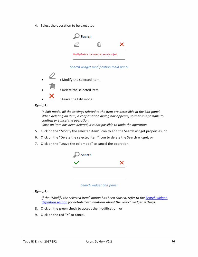
Tetra4D Enrich 2017 SP2 Users Guide – V2.2 76
4. Select the operation to be executed
Search widget modification main panel
• : Modify the selected item.
• : Delete the selected item.
• : Leave the Edit mode.
Remark:
In Edit mode, all the settings related to the item are accessible in the Edit panel. When deleting an item, a confirmation dialog box appears, so that it is possible to confirm or cancel the operation. Once an item has been deleted, it is not possible to undo the operation.
5. Click on the “Modify the selected item” icon to edit the Search widget properties, or
6. Click on the “Delete the selected item” icon to delete the Search widget, or
7. Click on the “Leave the edit mode” to cancel the operation.
Search widget Edit panel
Remark:
If the “Modify the selected item” option has been chosen, refer to the Search widget definition section for detailed explanations about the Search widget settings.
8. Click on the green check to accept the modification, or
9. Click on the red “X” to cancel.
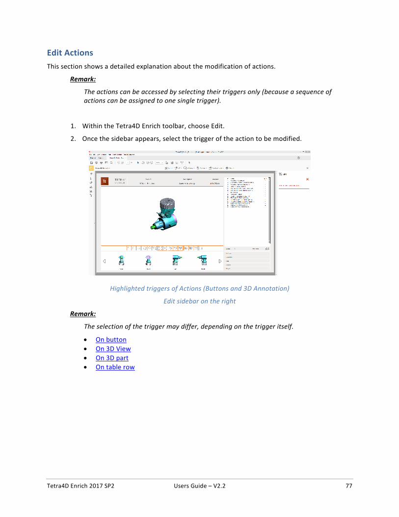
Tetra4D Enrich 2017 SP2 Users Guide – V2.2 77
Edit Actions
This section shows a detailed explanation about the modification of actions.
Remark:
The actions can be accessed by selecting their triggers only (because a sequence of actions can be assigned to one single trigger).
1. Within the Tetra4D Enrich toolbar, choose Edit.
2. Once the sidebar appears, select the trigger of the action to be modified.
Highlighted triggers of Actions (Buttons and 3D Annotation)
Edit sidebar on the right
Remark:
The selection of the trigger may differ, depending on the trigger itself.
• On button • On 3D View • On 3D part • On table row
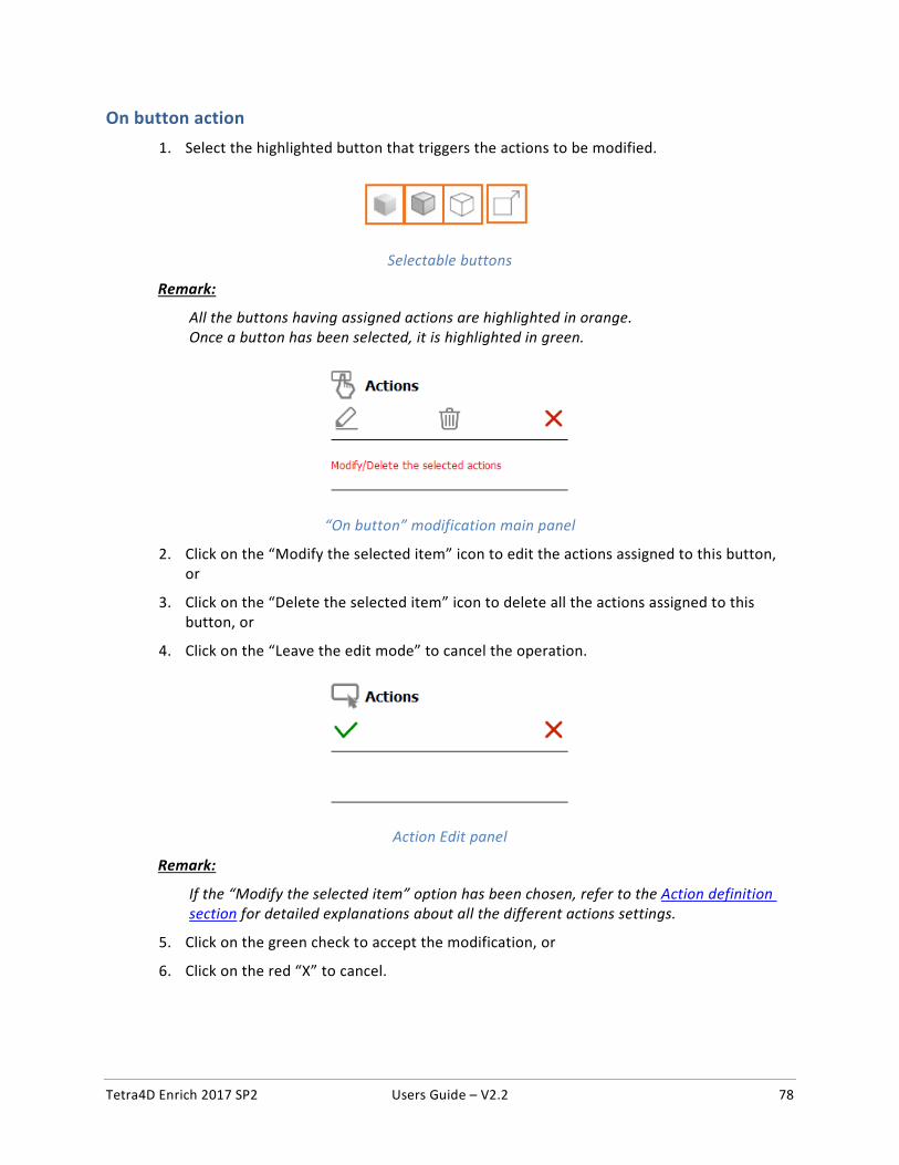
Tetra4D Enrich 2017 SP2 Users Guide – V2.2 78
On button action 1. Select the highlighted button that triggers the actions to be modified.
Selectable buttons
Remark:
All the buttons having assigned actions are highlighted in orange. Once a button has been selected, it is highlighted in green.
“On button” modification main panel
2. Click on the “Modify the selected item” icon to edit the actions assigned to this button, or
3. Click on the “Delete the selected item” icon to delete all the actions assigned to this button, or
4. Click on the “Leave the edit mode” to cancel the operation.
Action Edit panel
Remark:
If the “Modify the selected item” option has been chosen, refer to the Action definition section for detailed explanations about all the different actions settings.
5. Click on the green check to accept the modification, or
6. Click on the red “X” to cancel.
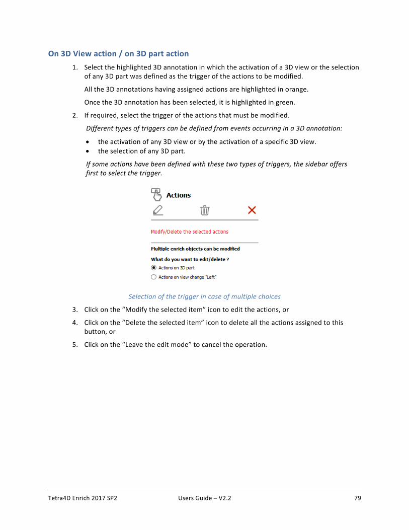
Tetra4D Enrich 2017 SP2 Users Guide – V2.2 79
On 3D View action / on 3D part action 1. Select the highlighted 3D annotation in which the activation of a 3D view or the selection
of any 3D part was defined as the trigger of the actions to be modified.
All the 3D annotations having assigned actions are highlighted in orange.
Once the 3D annotation has been selected, it is highlighted in green.
2. If required, select the trigger of the actions that must be modified.
Different types of triggers can be defined from events occurring in a 3D annotation:
• the activation of any 3D view or by the activation of a specific 3D view. • the selection of any 3D part.
If some actions have been defined with these two types of triggers, the sidebar offers first to select the trigger.
Selection of the trigger in case of multiple choices
3. Click on the “Modify the selected item” icon to edit the actions, or
4. Click on the “Delete the selected item” icon to delete all the actions assigned to this button, or
5. Click on the “Leave the edit mode” to cancel the operation.
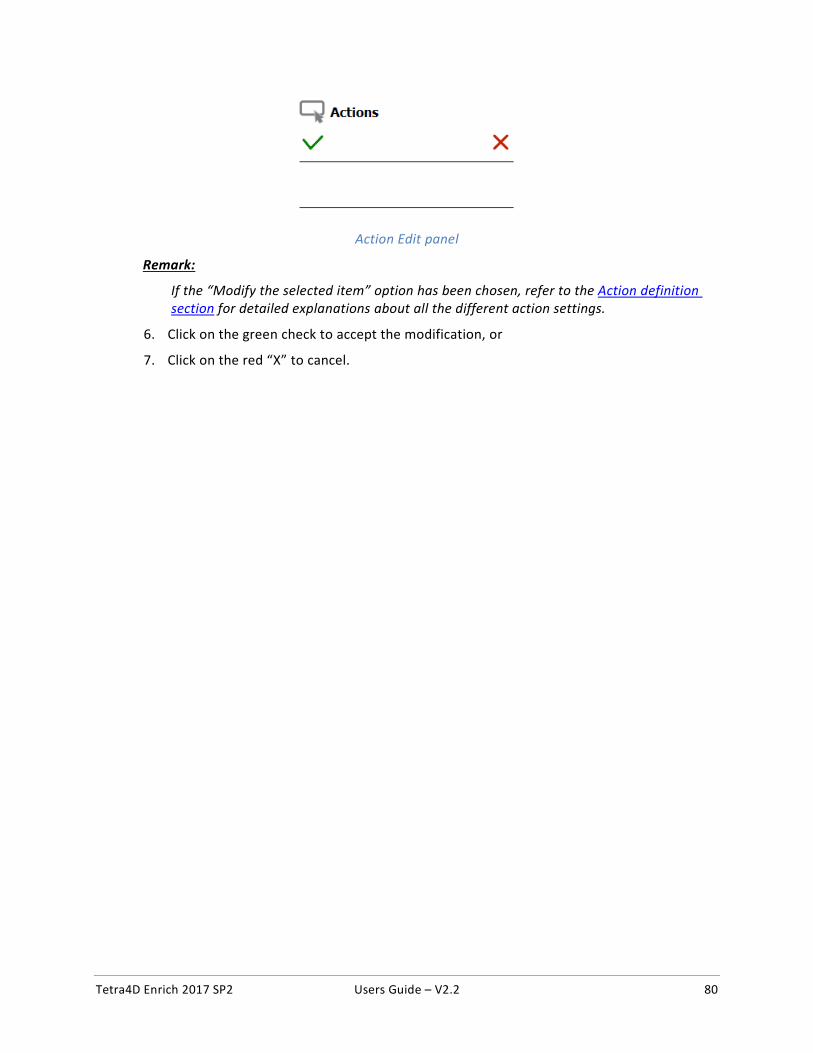
Tetra4D Enrich 2017 SP2 Users Guide – V2.2 80
Action Edit panel
Remark:
If the “Modify the selected item” option has been chosen, refer to the Action definition section for detailed explanations about all the different action settings.
6. Click on the green check to accept the modification, or
7. Click on the red “X” to cancel.
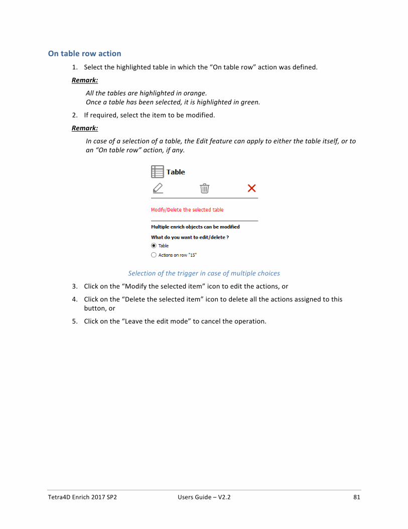
Tetra4D Enrich 2017 SP2 Users Guide – V2.2 81
On table row action 1. Select the highlighted table in which the “On table row” action was defined.
Remark:
All the tables are highlighted in orange. Once a table has been selected, it is highlighted in green.
2. If required, select the item to be modified.
Remark:
In case of a selection of a table, the Edit feature can apply to either the table itself, or to an “On table row” action, if any.
Selection of the trigger in case of multiple choices
3. Click on the “Modify the selected item” icon to edit the actions, or
4. Click on the “Delete the selected item” icon to delete all the actions assigned to this button, or
5. Click on the “Leave the edit mode” to cancel the operation.
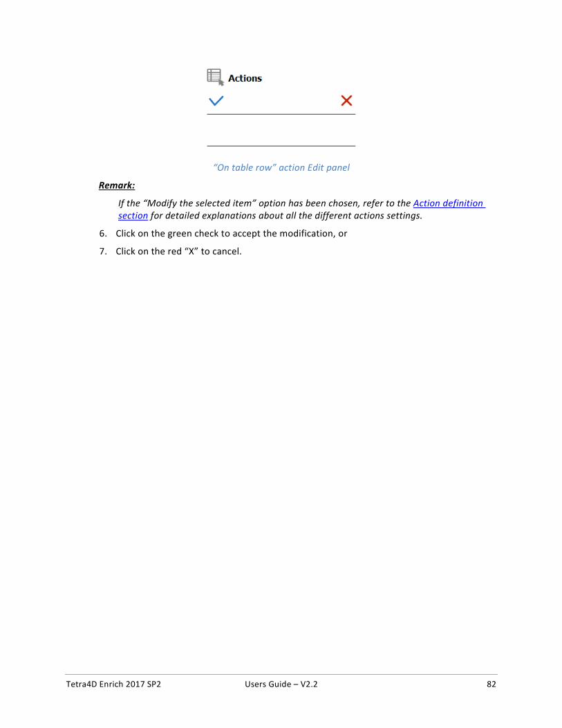
Tetra4D Enrich 2017 SP2 Users Guide – V2.2 82
“On table row” action Edit panel
Remark:
If the “Modify the selected item” option has been chosen, refer to the Action definition section for detailed explanations about all the different actions settings.
6. Click on the green check to accept the modification, or
7. Click on the red “X” to cancel.
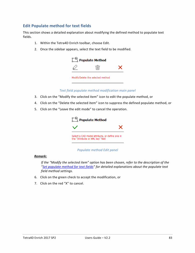
Tetra4D Enrich 2017 SP2 Users Guide – V2.2 83
Edit Populate method for text fields
This section shows a detailed explanation about modifying the defined method to populate text fields.
1. Within the Tetra4D Enrich toolbar, choose Edit.
2. Once the sidebar appears, select the text field to be modified.
Text field populate method modification main panel
3. Click on the “Modify the selected item” icon to edit the populate method, or
4. Click on the “Delete the selected item” icon to suppress the defined populate method, or
5. Click on the “Leave the edit mode” to cancel the operation.
Populate method Edit panel
Remark:
If the “Modify the selected item” option has been chosen, refer to the description of the “Set populate method for text fields” for detailed explanations about the populate text field method settings.
6. Click on the green check to accept the modification, or
7. Click on the red “X” to cancel.
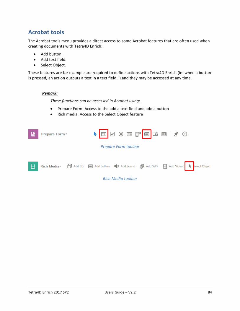
Tetra4D Enrich 2017 SP2 Users Guide – V2.2 84
Acrobat tools The Acrobat tools menu provides a direct access to some Acrobat features that are often used when creating documents with Tetra4D Enrich:
• Add button. • Add text field. • Select Object.
These features are for example are required to define actions with Tetra4D Enrich (ie: when a button is pressed, an action outputs a text in a text field…) and they may be accessed at any time.
Remark:
These functions can be accessed in Acrobat using:
• Prepare Form: Access to the add a text field and add a button • Rich media: Access to the Select Object feature
Prepare Form toolbar
Rich Media toolbar
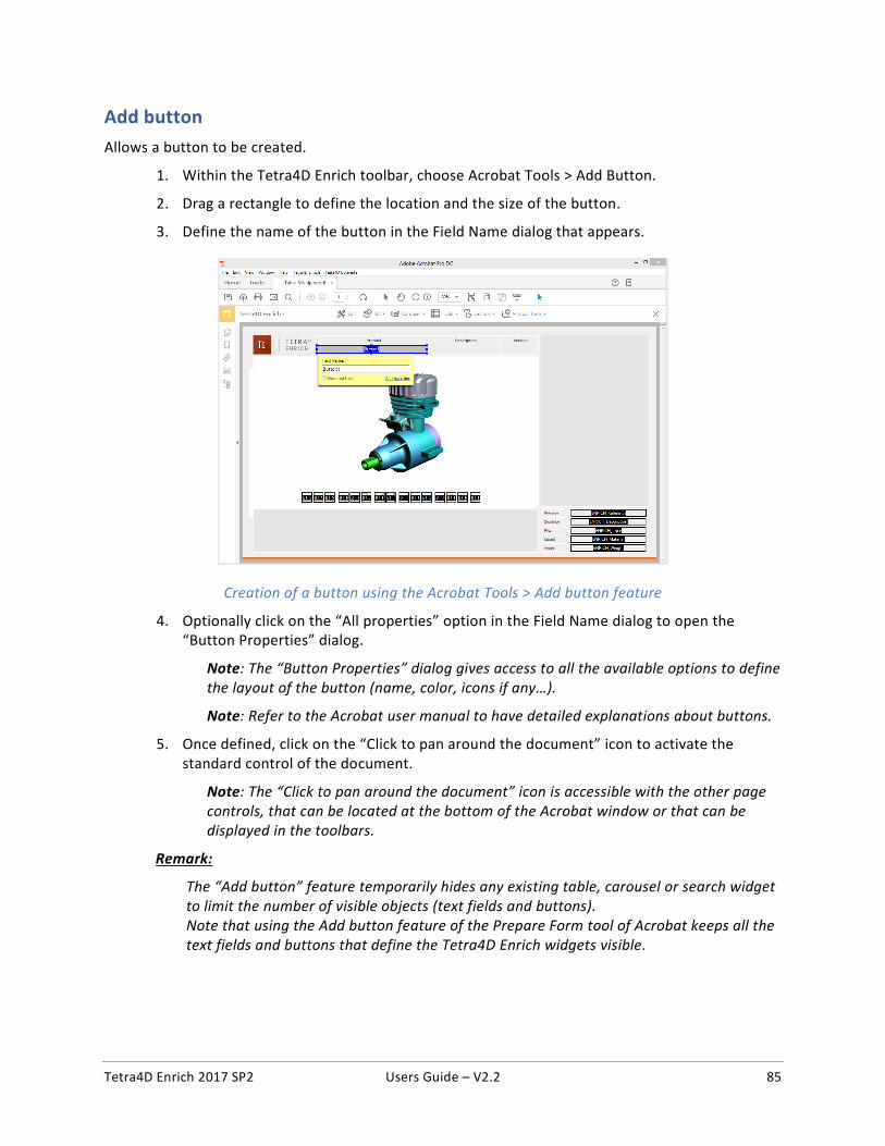
Tetra4D Enrich 2017 SP2 Users Guide – V2.2 85
Add button Allows a button to be created.
1. Within the Tetra4D Enrich toolbar, choose Acrobat Tools > Add Button.
2. Drag a rectangle to define the location and the size of the button.
3. Define the name of the button in the Field Name dialog that appears.
Creation of a button using the Acrobat Tools > Add button feature
4. Optionally click on the “All properties” option in the Field Name dialog to open the “Button Properties” dialog.
Note: The “Button Properties” dialog gives access to all the available options to define the layout of the button (name, color, icons if any…).
Note: Refer to the Acrobat user manual to have detailed explanations about buttons.
5. Once defined, click on the “Click to pan around the document” icon to activate the standard control of the document.
Note: The “Click to pan around the document” icon is accessible with the other page controls, that can be located at the bottom of the Acrobat window or that can be displayed in the toolbars.
Remark:
The “Add button” feature temporarily hides any existing table, carousel or search widget to limit the number of visible objects (text fields and buttons). Note that using the Add button feature of the Prepare Form tool of Acrobat keeps all the text fields and buttons that define the Tetra4D Enrich widgets visible.
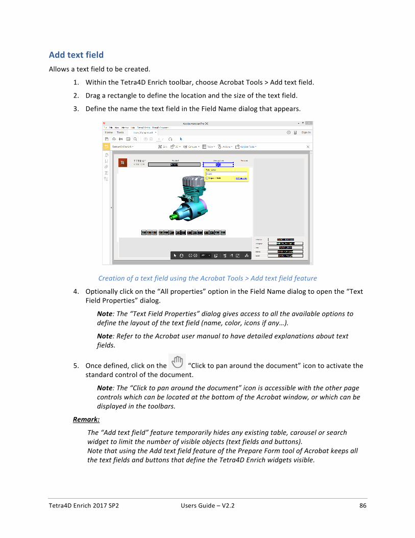
Tetra4D Enrich 2017 SP2 Users Guide – V2.2 86
Add text field Allows a text field to be created.
1. Within the Tetra4D Enrich toolbar, choose Acrobat Tools > Add text field.
2. Drag a rectangle to define the location and the size of the text field.
3. Define the name the text field in the Field Name dialog that appears.
Creation of a text field using the Acrobat Tools > Add text field feature
4. Optionally click on the “All properties” option in the Field Name dialog to open the “Text Field Properties” dialog.
Note: The “Text Field Properties” dialog gives access to all the available options to define the layout of the text field (name, color, icons if any…).
Note: Refer to the Acrobat user manual to have detailed explanations about text fields.
5. Once defined, click on the “Click to pan around the document” icon to activate the standard control of the document.
Note: The “Click to pan around the document” icon is accessible with the other page controls which can be located at the bottom of the Acrobat window, or which can be displayed in the toolbars.
Remark:
The “Add text field” feature temporarily hides any existing table, carousel or search widget to limit the number of visible objects (text fields and buttons). Note that using the Add text field feature of the Prepare Form tool of Acrobat keeps all the text fields and buttons that define the Tetra4D Enrich widgets visible.
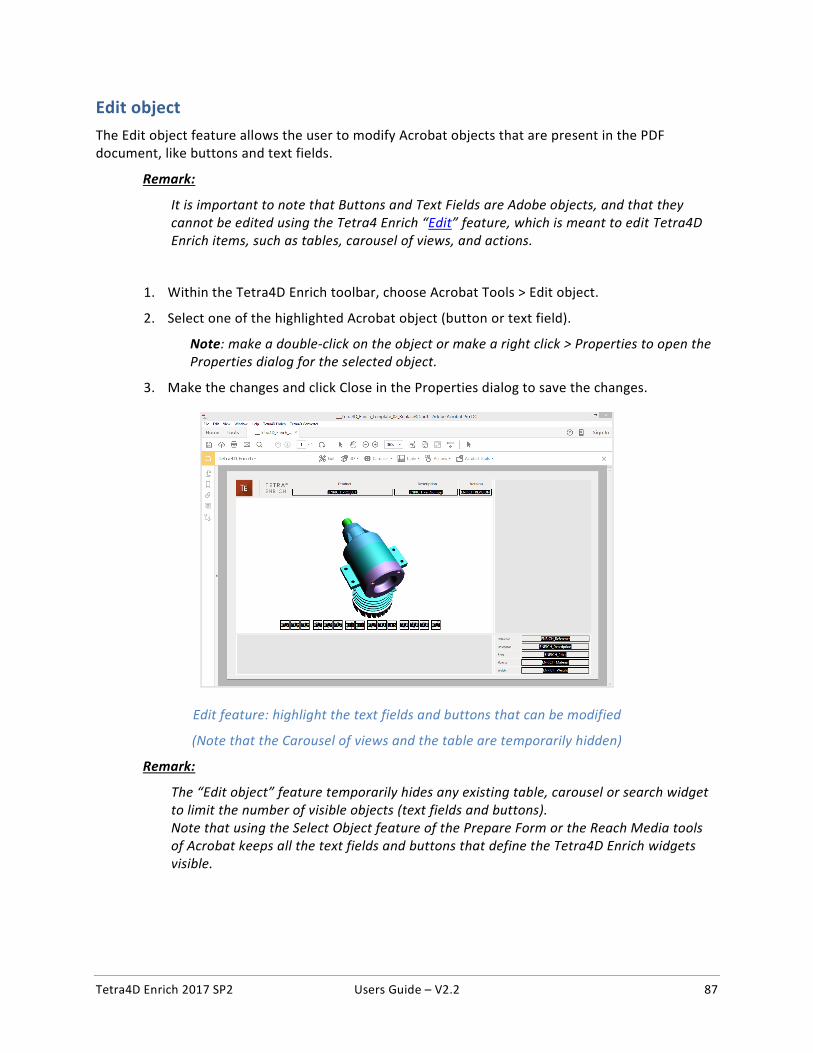
Tetra4D Enrich 2017 SP2 Users Guide – V2.2 87
Edit object The Edit object feature allows the user to modify Acrobat objects that are present in the PDF document, like buttons and text fields.
Remark:
It is important to note that Buttons and Text Fields are Adobe objects, and that they cannot be edited using the Tetra4 Enrich “Edit” feature, which is meant to edit Tetra4D Enrich items, such as tables, carousel of views, and actions.
1. Within the Tetra4D Enrich toolbar, choose Acrobat Tools > Edit object.
2. Select one of the highlighted Acrobat object (button or text field).
Note: make a double-click on the object or make a right click > Properties to open the Properties dialog for the selected object.
3. Make the changes and click Close in the Properties dialog to save the changes.
Edit feature: highlight the text fields and buttons that can be modified
(Note that the Carousel of views and the table are temporarily hidden)
Remark:
The “Edit object” feature temporarily hides any existing table, carousel or search widget to limit the number of visible objects (text fields and buttons). Note that using the Select Object feature of the Prepare Form or the Reach Media tools of Acrobat keeps all the text fields and buttons that define the Tetra4D Enrich widgets visible.
Tetra4D Enrich 2017 SP2 Users Guide – V2.2 88
Set populate method for text fields The “Set populate method for text fields” function allows you to define how to populate text fields present in the PDF document, with information coming from:
• 3D File attributes,
• CAD model attributes,
• XML.
For example, it is possible to have a title block in the PDF document where different text fields are populated with information coming from the 3D CAD data that are in the document (name of the CAD file, attribute information like Material, Revision…)
Remark:
This features enables to directly populate the text fields with information present in the PDF document, and is also suitable for a template usage of the PDF document since the defined method to populate the text fields is stored in the PDF itself. In case of re-use of an existing PDF document where this feature was used to define how to populate the text fields, the values present in these text fields will be automatically updated when a Replace 3D is performed.
Definition of a methods to populate text fields
Remark:
The text fields must be defined prior the definition of method to populate them. Refer to “Add text field” for instructions on how to create text fields.
1. Within the Tetra4D Enrich toolbar, choose Acrobat Tools > Set populate method for text fields.
Note: The existing text fields in the active page of the PDF document are highlighted in orange.
2. Select a text field.
Note: Once selected, the text field is highlighted in blue.
3. In the Populate method panel which appears on the right, select the source that will be used to populate the selected field.
Note: Refer to Description of the different methods to populate text fields to have detailed explanations about the proposed methods.
4. Depending on the selected source, select the attribute in the “Attributes list” sub-panel, or manually define the attribute name if not present in the list or the XML key in the “Attribute or XML key” sub-panel.
5. Click on the green check button “Save and populate fields” icon to populate the text field with the value and save the methods, or
6. Click on the red “X” “Cancel the modifications” icon to discard the changes.
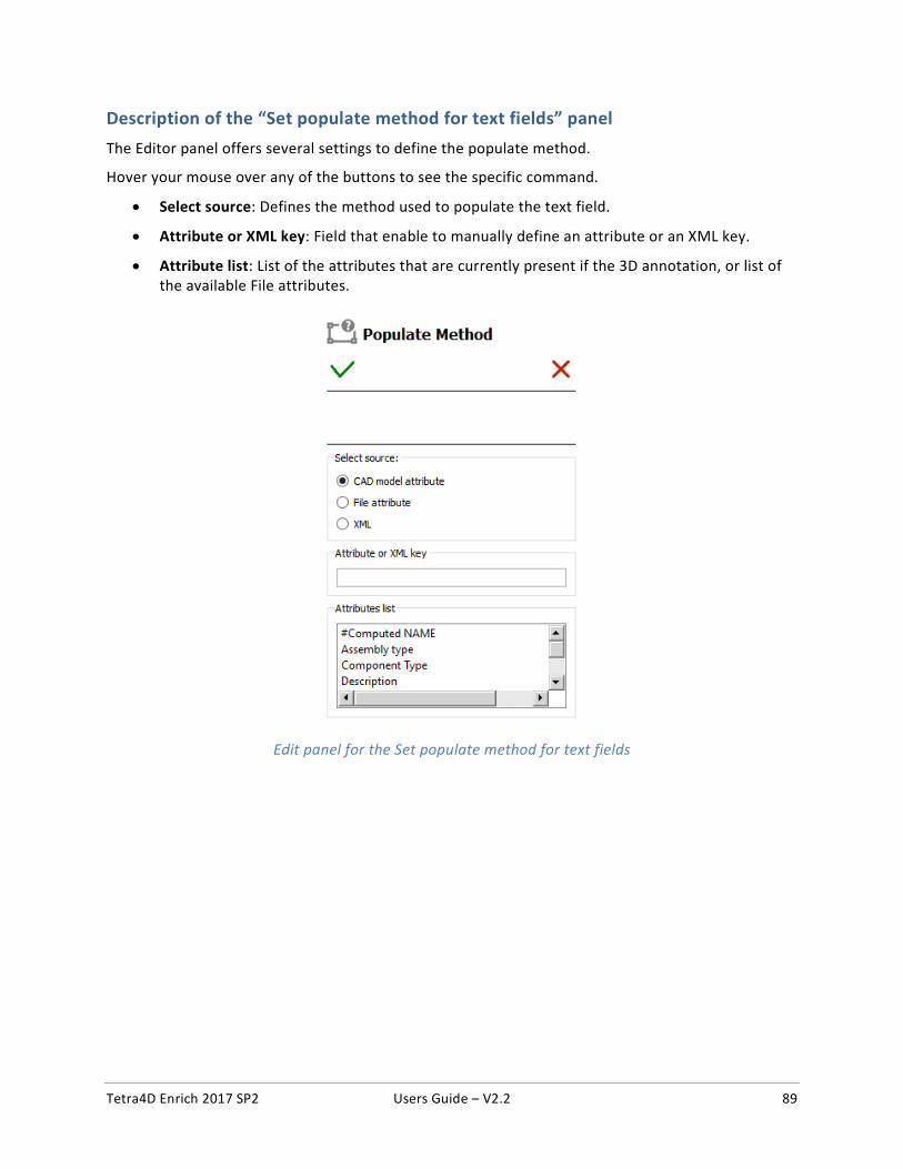
Tetra4D Enrich 2017 SP2 Users Guide – V2.2 89
Description of the “Set populate method for text fields” panel The Editor panel offers several settings to define the populate method.
Hover your mouse over any of the buttons to see the specific command.
• Select source: Defines the method used to populate the text field.
• Attribute or XML key: Field that enable to manually define an attribute or an XML key.
• Attribute list: List of the attributes that are currently present if the 3D annotation, or list of the available File attributes.
Edit panel for the Set populate method for text fields
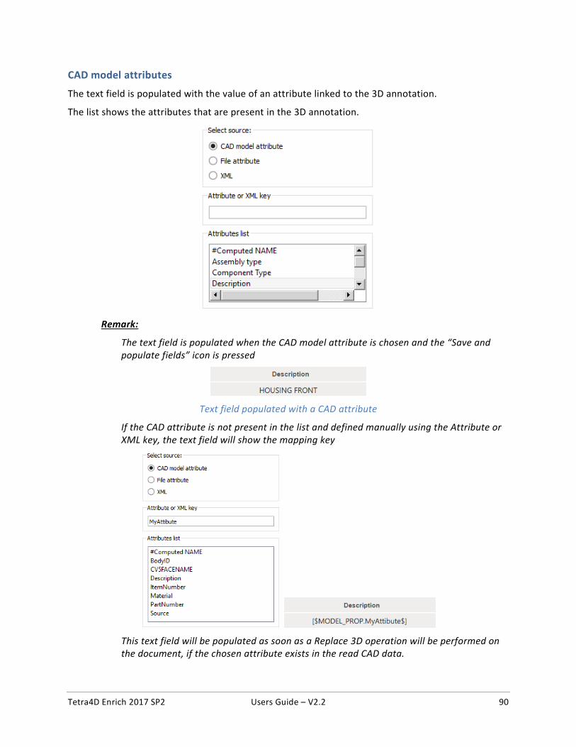
Tetra4D Enrich 2017 SP2 Users Guide – V2.2 90
CAD model attributes
The text field is populated with the value of an attribute linked to the 3D annotation.
The list shows the attributes that are present in the 3D annotation.
Remark:
The text field is populated when the CAD model attribute is chosen and the “Save and populate fields” icon is pressed
Text field populated with a CAD attribute
If the CAD attribute is not present in the list and defined manually using the Attribute or XML key, the text field will show the mapping key
This text field will be populated as soon as a Replace 3D operation will be performed on the document, if the chosen attribute exists in the read CAD data.
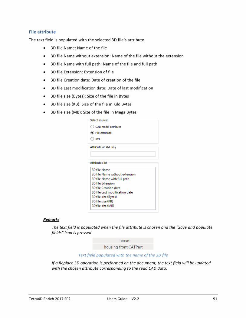
Tetra4D Enrich 2017 SP2 Users Guide – V2.2 91
File attribute
The text field is populated with the selected 3D file’s attribute.
• 3D file Name: Name of the file
• 3D file Name without extension: Name of the file without the extension
• 3D file Name with full path: Name of the file and full path
• 3D file Extension: Extension of file
• 3D file Creation date: Date of creation of the file
• 3D file Last modification date: Date of last modification
• 3D file size (Bytes): Size of the file in Bytes
• 3D file size (KB): Size of the file in Kilo Bytes
• 3D file size (MB): Size of the file in Mega Bytes
Remark:
The text field is populated when the file attribute is chosen and the “Save and populate fields” icon is pressed
Text field populated with the name of the 3D file
If a Replace 3D operation is performed on the document, the text field will be updated with the chosen attribute corresponding to the read CAD data.
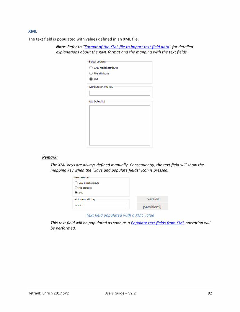
Tetra4D Enrich 2017 SP2 Users Guide – V2.2 92
XML
The text field is populated with values defined in an XML file.
Note: Refer to “Format of the XML file to import text field data” for detailed explanations about the XML format and the mapping with the text fields.
Remark:
The XML keys are always defined manually. Consequently, the text field will show the mapping key when the “Save and populate fields” icon is pressed.
Text field populated with a XML value
This text field will be populated as soon as a Populate text fields from XML operation will be performed.
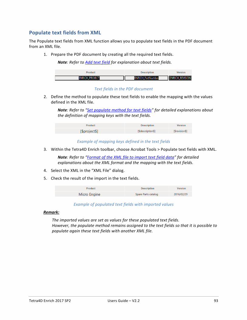
Tetra4D Enrich 2017 SP2 Users Guide – V2.2 93
Populate text fields from XML The Populate text fields from XML function allows you to populate text fields in the PDF document from an XML file.
1. Prepare the PDF document by creating all the required text fields.
Note: Refer to Add text field for explanation about text fields.
Text fields in the PDF document
2. Define the method to populate these text fields to enable the mapping with the values defined in the XML file.
Note: Refer to “Set populate method for text fields” for detailed explanations about the definition of mapping keys with the text fields.
Example of mapping keys defined in the text fields
3. Within the Tetra4D Enrich toolbar, choose Acrobat Tools > Populate text fields with XML.
Note: Refer to “Format of the XML file to import text field data” for detailed explanations about the XML format and the mapping with the text fields.
4. Select the XML in the “XML File” dialog.
5. Check the result of the import in the text fields.
Example of populated text fields with imported values
Remark:
The imported values are set as values for these populated text fields. However, the populate method remains assigned to the text fields so that it is possible to populate again these text fields with another XML file.
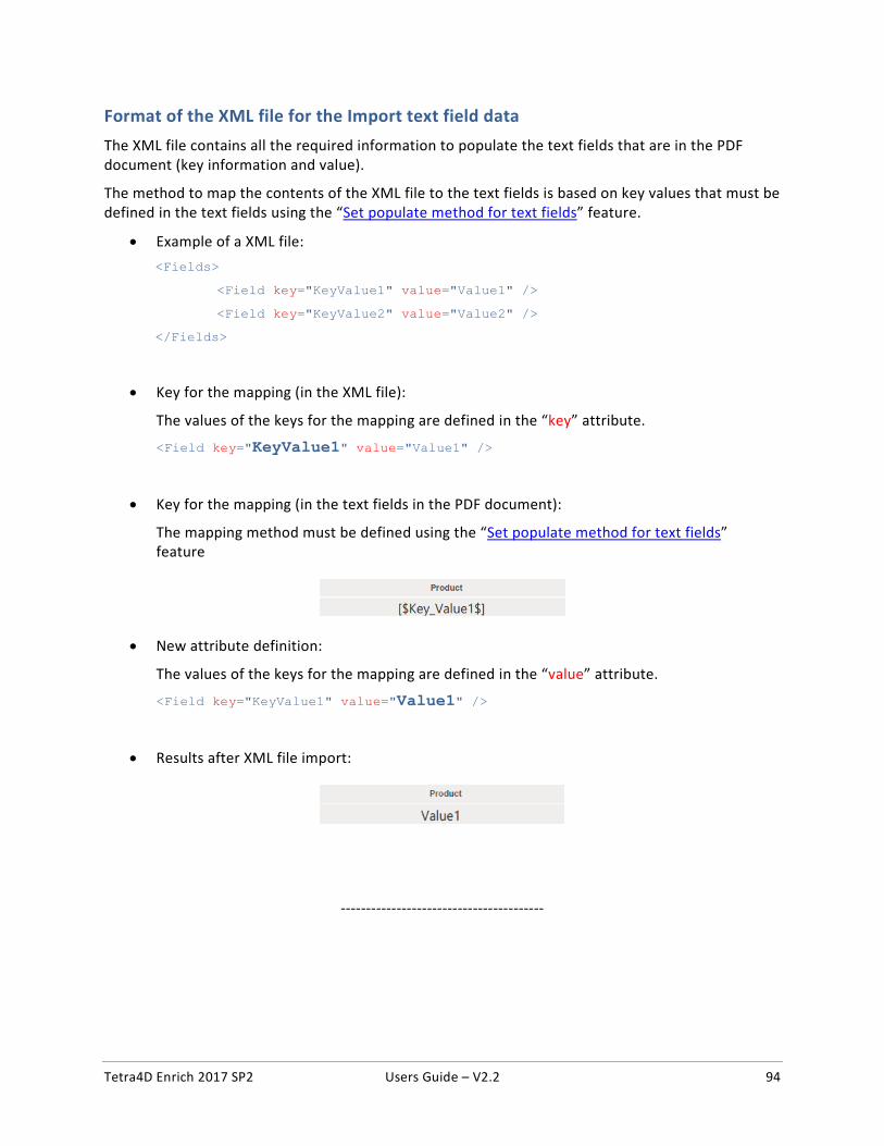
Tetra4D Enrich 2017 SP2 Users Guide – V2.2 94
Format of the XML file for the Import text field data The XML file contains all the required information to populate the text fields that are in the PDF document (key information and value).
The method to map the contents of the XML file to the text fields is based on key values that must be defined in the text fields using the “Set populate method for text fields” feature.
• Example of a XML file: <Fields>
<Field key="KeyValue1" value="Value1" />
<Field key="KeyValue2" value="Value2" />
</Fields>
• Key for the mapping (in the XML file):
The values of the keys for the mapping are defined in the “key” attribute.
<Field key="KeyValue1" value="Value1" />
• Key for the mapping (in the text fields in the PDF document):
The mapping method must be defined using the “Set populate method for text fields” feature
• New attribute definition:
The values of the keys for the mapping are defined in the “value” attribute.
<Field key="KeyValue1" value="Value1" />
• Results after XML file import:
----------------------------------------