Embed Size (px)
Citation preview

ElecoTek INC1640 West Hubbard StreetUnit BChicago,IL 60622312-631-3692https://www.elecotek.com
Test record
TEST PASSED
Test performed Components usedDate: 07/07/2016 Ansur Version 3.0.0Record: 13872572.mtr Plug-In: AVPI Version 2.4.11
Plug-In: IDA4 Version 1.0.1
Template:PlumA+InfusionPump.mtt
Plug-In: ESA620 Version 1.1.11
Template version: 1.0.46
Test setup
Selections
Service events performed Standards performedUser defined AAMI/NFPA-99 (M)
Device under test
Serial Number 13872572 Type Infusion PumpStatus Certified Model Plum A+Manufacturer Hospira Location ElecoTek
MTI Data
Test instrument Serial number Firmware versionIDA-4 Plus #1 11960 2.10ESA 620 9790056 v2.10
ElecoTek_Inc 07/07/2016
Test Record 1 Page 1 of 26

Signatures
ElecoTek INCDD24E79E-2559-4948-BB7D-18CE363DE78D
Test resultTest element Test type FailCLEANING AND SANITIZING Checklist
Procedure:
Inspect and clean the infuser after each use. In addition,establish a regular cleaning schedule for the device. Before cleaning, turn off the infuser and disconnect from AC power. Clean the exposed surfaces of the infuser with a soft, lint-free cloth moistened with one of the cleaning solutions recommended.Result: Recorded value
Confirm that the following labels are present:- Close Lever Label(Lever Door Open)- Close Leverw/Arrow Label- Rear Caution Label- Battery Label(Internal)- Caution Label- Logo Label- Service Revision Level Label(Driver)- Product I.D. Label (Driver)- Product ID Label (Module)- Switchport Label- (2) MAC AddressLabels(Wireless)- Push Label(Wireless)- Side Labels
Pass
Inspect the labels for legibility and peeling. To replace a label, contact Hospira
Pass
LABELS INSPECTION ChecklistProcedure:
Preventive maintenance should be performed at least once every 12 months and each timethe infuser is serviced. Replace components as required by visual inspection and test results.
Result: Recorded value
Turn off the infuser and disconnect the device from AC power
Pass
Remove the retainer and power cord as described.
Pass
ElecoTek_Inc 07/07/2016
Test Record 1
Fluke Biomedical Ansur Test Report
Page 2 of 26

Test element Test type FailResult: Recorded value Inspect the retainer for cracks, breaks, or missing parts of the retainer body.
Pass
Inspect both ends of the power cord for any signs of electrical arcing, burn marks,or heat scorching or melting.
Pass
Inspect the plug end of the power cord for bent blades or a bent or missing groundpin.
Pass
Inspect the Velcro strap for damage.
Pass
When inspections are completed, reassemble the power cord to the infuseras described.
Pass
Connect the infuser to AC power and confirm the AC indicator is lit.
Pass
AC POWER CORD, RETAINER, AND VELCRO STRAP
Checklist
Result: Recorded value Turn off the infuser and disconnect the device from AC power
Pass
Remove the retainer and power cord as described in Section 7.2.5
Pass
Inspect the retainer for cracks, breaks, or missing parts of the retainer body.
Pass
Inspect both ends of the power cord for any signs of electrical arcing, burn marks,or heat scorching or melting.
Pass
Inspect the plug end of the power cord for bent blades or a bent or missing groundpin. If any damage is observed, replace the power cord.
Pass
Inspect the Velcro strap for damage. If any damage is observed, replace the strap.
Pass
When inspections are completed, reassemble the power cord to the infuseras described in Section 7.2.5.
Pass
Connect the infuser to AC power and confirm the AC indicator is lit.
Pass
FRONT ENCLOSURE, REAR ENCLOSURE, CASSETTE
Checklist
Result: Recorded value
Inspect the front and rear enclosures for cracks, chips, and gouges.
Pass
Inspect the enclosures for stains and discolorations.
Pass
ElecoTek_Inc 07/07/2016
Test Record 1
Fluke Biomedical Ansur Test Report
Page 3 of 26

Test element Test type FailResult: Recorded value Inspect the rear enclosure for the presence and tightness of the six assembly screws.
Pass
Inspect the cassette door for cracks and chips.
Pass
Inspect the door lever for cracks.
Pass
Move the door lever to the OPEN position. Confirm that the door opens smoothly.If the door does not open smoothly, check for debris or dried fluid buildup.Clean the mechanism as described
Pass
Move the door lever to the CLOSED position. Confirm smooth operation as described
Pass
DOOR ROLLER INSPECTION AND TEST ChecklistResult: Recorded value
Open the cassette door. Pass Push the door release tab to the right to unlatch the door.
Pass
Verify that the retaining ring that secures the roller wheel to the pin is seatedproperly and the pin is not bent
Pass
Ensure the door roller spins smoothly with a finger touch.
Pass
FLUID SHIELD INSPECTION ChecklistProcedure:
Equipment required for the fluid shield inspection is a 0.025 inch (0.65 mm) feeler gauge(plastic or metal).Result: Recorded value
Release the door so that it lays flat. Press the door release tab to the right and openthe cassette door all the way.
Pass
Attempt to insert the feeler gauge (held perpendicular to the fluid shield) into bothgaps between the mechanism assembly and the fluid shield. If you are not able to insert the feeler gauge into the gaps between themechanism assembly and the fluid shield, the fluid shield is in an acceptablecondition.
Pass
ElecoTek_Inc 07/07/2016
Test Record 1
Fluke Biomedical Ansur Test Report
Page 4 of 26

Test element Test type FailResult: Recorded value Inspect the sensor and control pins for damage and built-up contamination aroundeach pin. If any pins are broken or chipped, contactfor repair. If there is accumulation of dried fluids around any pins, clean the areaaround the pin following the guidelines.
Pass
Inspect the cassette presence detector boot for damage.
Pass
DISTAL PRESSURE PIN INSPECTION ChecklistProcedure:
The distal pressure pin is the black pin.Result: Recorded value
Release the door so that it lays flat. Press the door release tab to the right and openthe cassette door all the way
Pass
Inspect the distal pressure pin to determine that it is not damaged or broken.
Pass
PROXIMAL PRESSURE PIN INSPECTION ChecklistProcedure:
The proximal pressure pin is the white pin.Result: Recorded value
Release the door so that it lays flat. Press the door release tab to the right and openthe cassette door all the way.
Pass
Inspect the pin to determine that it is not damaged or broken
Pass
RUBBER FOOT PAD INSPECTION (if available) ChecklistProcedure:
Some versions of the Plum A+ do not have rubber foot padsResult: Recorded value
Inspect for missing or loose rubber foot pads, and rubber foot pads that are startingto peel away from the enclosure.
Pass
POLE CLAMP INSPECTION AND TEST ChecklistResult: Recorded value
Confirm that the pole clamp assembly is securely attached to the rearof the enclosure. Tighten the assembly if it is loose
Pass
ElecoTek_Inc 07/07/2016
Test Record 1
Fluke Biomedical Ansur Test Report
Page 5 of 26

Test element Test type FailResult: Recorded value Confirm that the rubber pad (wireless devices only) is present on the inside surfaceof the pole clamp extrusion. If the pad is missing, replace the extrusion. Rubber pads are not present on non-wireless Plum A+ infusers.
Pass
Confirm that the plastic shaft tip is present at the end of the threaded pole clampshaft.
Pass
Tighten and loosen the threaded pole clamp shaft so that it moves through the entirelength of the threads. Confirm that the shaft moves smoothly and does not bindalong its length.
Pass
Mount the infuser on an IV pole and fully tighten the clamp. Ensure that the infuseris held firmly and does not slide on the IV pole.securely, replace the clamp.
Pass
BATTERY INSPECTION AND REPLACEMENT ChecklistProcedure:
The sealed, lead-acid battery must be replaced at least once every12 months. .Result: Recorded value
Turn off the infuser and disconnect the device from AC power. The Charge/Lineindicator LED on the keypad will turn off. Wait five minutes for the microprocessor to save data and completethe turn off sequence before unplugging the battery.
Pass
remove the screw that attaches the battery doorto the infuser, and remove the door.
Pass
Carefully pull the battery and wire harness assembly out of the enclosureand disconnect it from the infuser’s internal wiring at the inline connector.
Pass
Inspect the battery compartment for any debris. If debris is present, wipe or brushthe debris out of the compartment.
Pass
Inspect the battery door and replace, if damaged or cracked.
Pass
ElecoTek_Inc 07/07/2016
Test Record 1
Fluke Biomedical Ansur Test Report
Page 6 of 26

Test element Test type FailResult: Recorded value Inspect the battery door pad on the battery door to ensure the pad is attachedand is not damaged. If the pad is damaged, replace either the pad or the completebattery door assembly.
Pass
Inspect the battery door gasket on the battery door to ensure that the gasketis attached and is not damaged. The battery gasket may not be present on some versionsof the infuser.
Pass
Connect the replacement battery and wire harness assembly to the infuser’sinternal wiring harness at the inline connector. The inline connector is keyed so thatthe cables cannot be incorrectly connected.
Pass
Carefully insert the battery and wire harness assembly into its compartment withthe terminals facing upward. Confirm the battery harness is not pinched between the batteryand the enclosure.
Pass
Reinstall the battery door using the screw that was removed and returnthe infuser to its upright position
Pass
Connect the device to AC power and verify that the Charge/Line indicator LEDon the keypad is lit.
Pass
Access the BIOMED SETTINGS screen and press the [CHANGEBATTERY] softkey. The infuser does not provide a confirmation message whenthe [CHANGE BATTERY] softkey is pressed.
Pass
Verify that the battery charge level indicator on the LCD display shows at least one,but not more than three white bars. If the indicator shows more than three bars,press the [CHANGE BATTERY] softkey again. If the indicator still shows more thanthree bars or shows zero bars, repeat the steps in this section.
Pass
Press [ON/OFF] to turn off the infuser.
Pass
KEYPAD INSPECTION Checklist
ElecoTek_Inc 07/07/2016
Test Record 1
Fluke Biomedical Ansur Test Report
Page 7 of 26

Test element Test type FailResult: Recorded value Inspect the keypad for tears, cracks, or edges lifting away from the infuser.
Pass
Inspect the keypad for worn or illegible numbers or letters. If letters or numbersare not readable
Pass
Inspect the keypad domes by pressing each number, word, and symbol to confirmthat the domes have mechanical strength and provide tactile feedback.
Pass
Confirm that the green [START] button, red [STOP] button, and yellow [ON/OFF]button have retained their color.
Pass
DISPLAY AND INDICATORS INSPECTION ChecklistResult: Recorded value
Connect the power cord to the mains supply, and confirm that the CHARGE LED
Pass
Rotate the infuser so that the rear of the device is facing to the front.
Pass
Confirm that the keypad lockout switch is in the OFF (down) position
Pass
Rotate the infuser back to its original position so that the display is facing forward
Pass
Press the [ON/OFF] key to power on the infuser, and observe the infuseras it performs its self test
Pass
Confirm that the two line flow LEDs flash, and that there are two audible sounds -one at the beginning of the self test and one at the end of the self test.
Pass
If the audible sounds do not occur, replace the piezo alarm assembly
Pass
Observe the display area. Confirm that the display is clear and readable.
Pass
Pass
KEYPAD LOCKOUT SWITCH INSPECTION ChecklistResult: Recorded value
Inspect for the presence of the keypad lockout switch and ensure the switchis not broken.
Pass
Inspect for a loose or dislodged switch.
Pass
Preparing the Primary Line (Basic Test Setup) .1 ChecklistProcedure:
The Basic test setup consists of Primed, primary and secondary lines attached
ElecoTek_Inc 07/07/2016
Test Record 1
Fluke Biomedical Ansur Test Report
Page 8 of 26

Test element Test type Fail
to fluidbags. The cassette is inserted into the infuser and the distal (patient) end of the tubing isplaced in a collection container. The Basic test setup is shown in Figure 5-18:.Result: Recorded value Prepare the primary line, proceed as follows to fill the cassette and tubing on theprimary PlumSet with liquid (that is, prime it), eliminating all air, and then load thecassette into the infuser.
Pass
Place the infuser on a bench or attach it to an IV pole.
Pass
Press the cassette flow regulator in to make ensure it is closed
Pass
If using a glass IV container, open the filter vent cover above the drip chamber. Ifusing a plastic IV container, ensure that the filter vent cover is closed
Pass
Using a twisting motion, insert the piercing pin into the outlet on a water container. Do not position the container above the infuser while insertingthe piercing pin.
Pass
Suspend the container on an IV pole.
Pass
Check for leaks Pass Squeeze the drip chamber to fill it about 1/2 full or to the score mark. Do not completely fill the drip chamber
Pass
Invert the cassette so that the secondary port is pointing down
Pass
Slowly open the flow regulator by turning it counter-clockwise (see Figure 5-24).When the first drop appears in the pumping chamber, turn the cassette upright.
Pass
Tap and clear air from the cassette, Y-site, and tubing to remove all air from theremainder of the administration set
Pass
Push in the flow regulator to close it (see Figure 5-26). Check the distal end of thetubing to confirm that there is no flow.
Pass
Close all clamps on the proximal and distal lines
Pass
Pass
Loading the Cassette (Basic Test Setup) .2 Checklist
ElecoTek_Inc 07/07/2016
Test Record 1
Fluke Biomedical Ansur Test Report
Page 9 of 26

Test element Test type FailResult: Recorded value Lift the lever to open the cassette door
Pass
Grasp the cassette by the finger grip
Pass
Slide the cassette into the door guide
Pass
Press the lever down to close the cassette door.
Pass
Open all clamps Pass Check the distal end of the tubing to confirm that there is no flow and that no kinksappear in the tubing.
Pass
Ensure that the score mark on the drip chamber is 12 to 24 inches higher than thecassette.
Pass
Place the distal end of the tubing in the collection container.
Pass
Preparing the Secondary Line (Basic Test Setup) .3 ChecklistResult: Recorded value
Insert the piercing pin into the secondary container outlet using a twisting motion
Pass
Do not position the container above the infuser while insertingthe piercing pin.
Pass
Suspend the container on an IV pole.
Pass
Check the secondary container for leaks.
Pass
Squeeze the drip chamber to fill it about 1/2 full or to the score mark. Do not completely fill the drip chamber.
Pass
Slowly open the roller clamp to allow fluid to flow into the secondary tubing.
Pass
After all air is removed, close the roller clamp
Pass
If the cassette has a Clave secondary port: Insert the end of the secondaryline into the Clave. Move the Option-Lok collar over the Clave and twistclockwise to secure the line to the port
Pass
If the cassette has a capped secondary port: Confirm that the cassette dooris closed, and then loosen and remove the white cap. Discard the cap. Insert theend of the secondary line into the port and twist clockwise to secure the line tothe port
Pass
ElecoTek_Inc 07/07/2016
Test Record 1
Fluke Biomedical Ansur Test Report
Page 10 of 26

Test element Test type FailResult: Recorded value Open the cassette door to access to the white cap, firstclose all clamps on the primary and secondary lines to avoid spilling fluid whenthe cap is removed, and then lift the lever to open the cassette door. Remove and discard the cap, attach the secondary line,close the cassette door and then open all clamps.
Pass
Arrange the fluid container so that the score mark on the drip chamber is 12 to 24inches higher than the cassette.The secondary container does not need to be higher than the primarycontainer for accurate delivery of a piggyback infusion.
Pass
Pass
PROXIMAL AIR-IN-LINE TEST SETUP ChecklistResult: Recorded value
Cut to remove the proximal bubble sensor bulb tips as shown. Keep the knife parallel with the plastic to avoid cutting too far into the sensor bulb, which may cause leakage.
Pass
permanent marker, write "Proximal" and the date on the drip chamber
Pass
DISTAL AIR-IN-LINE TEST SETUP ChecklistResult: Recorded value
Cut to remove the distal bubble sensor bulb tips as shown. Keep the knife parallel with the plastic to avoid cutting too far intothe sensor bulb, which may cause leakage.
Pass
permanent marker, write "Distal" and the date on the drip chamber
Pass
PRIMING A RUN-IN CASSETTE ASSEMBLY ChecklistResult: Recorded value
Primed run-in cassettes are required for Proximal Air-in-Line and Distal Air-in-Linetests. The run-in cassette has tubing that is arranged so that fluid is pumped in acontinuous loop, as shown
Pass
The proximal and distal portions of the run-in cassette must be primed separately, usingtwo different procedures.
Pass
ElecoTek_Inc 07/07/2016
Test Record 1
Fluke Biomedical Ansur Test Report
Page 11 of 26

Test element Test type Fail
Priming the Run-In Cassette and Proximal Tubing ChecklistResult: Recorded value Prime the cassette and proximal tubing parts of the run-incassette assembly using the Backprime feature of the infuser. During backpriming, thewhite cap is off to allow air to escape as fluid fills the cassette and tubing.
Pass
Remove the top from the run-in cassette, fill the drip chamber about 2/3 full, andthen put the top back on. Do not fill the drip chamber any more than 2/3 full or water may spillout the top of the cassette during backpriming.
Pass
Insert the run-in cassette into the infuser and close the door.
Pass
Remove the white cap on the run-in cassette, taking care not to spill any water intothe infuser. The run-in cassette is now installed in the infuser with the white cap off.
Pass
Turn on the infuser. During the self test, the infuser will issue a cassette test failurealarm.
Pass
Press and hold [BACKPRIME] to pump water from the drip chamber into theproximal lines and cassette.
Pass
When bubbles are no longer being pushed into the drip chamber, release the[BACKPRIME] key. The cassette test will proceed.
Pass
When the cassette test completes with no alarms, replace the white cap.
Pass
Pass
Priming the Distal Tubing Loop ChecklistProcedure:
After the cassette and proximal tubing are primed, the cassette test will succeed. A distalair alarm may occur the first time a test infusion is run, however, because Backprimeonly affects tubing that is proximal to the cassette. The following procedure describeshow to manually pump air out of the distal tubing.Result: Recorded value
Open the cassette door and remove the run-in cassette. Close the cassette door.
Pass
ElecoTek_Inc 07/07/2016
Test Record 1
Fluke Biomedical Ansur Test Report
Page 12 of 26

Test element Test type FailResult: Recorded value Remove the top of the run-in cassette and add water to bring the level in the dripchamber to about 2/3 full. Replace the top.
Pass
Check the run-in cassette for leaks, especially around the sensor bulbs that werecut. If there is any leakage, replace the run-in cassette.
Pass
Keeping the cassette upright, remove the white cap.
Pass
Pull out the flow regulator
Pass
Press in firmly on the pumping chamber to pump air out of the chamber
Pass
Continue to press on the pumping chamber as you use your other hand to pushthe flow regulator closed. This prevents the air from returning tothe pumping chamber
Pass
Release the pumping chamber and flow regulator
Pass
Repeat steps until all distal air is pumped out of the tubing.
Pass
Replace the cap. The run-in cassette is now ready for use
Pass
Remove the cassette from the infuser.
Pass
Distal Occlusion Test Setup ChecklistProcedure:
Add a three-way stopcock andDigital Pressure Meter (DPM) to the distal tubing on the Basic test setup. Result: Recorded value
Attach the pressure sensor connector on the DPM to a compatible port (male orfemale) on the three-way stopcock
Pass
Insert the distal tubing on the Basic test setup into a female port on the three-waystopcock and turn the Option-Lok connector clockwise to secure the tubing to theport
Pass
Place the DPM connector at a height of 0 +/- 12 inches from the midline of the pumpingchamber on the cassette
Pass
SELF TEST ChecklistProcedure:
Use the Basic test setup and proceed
ElecoTek_Inc 07/07/2016
Test Record 1
Fluke Biomedical Ansur Test Report
Page 13 of 26

Test element Test type FailResult: Recorded value Plug the power cord into a grounded AC outlet. Verify that the charge/line indicatoris lit and an alarm sounds
Pass
Without a cassette installed, press [ON/OFF] to turn on the infuser. The LCD screenbriefly displays the SELF TEST screen.
Pass
If MedNet is installed, an Area Selection or CCA Selection screen appears. Choosea care area and press [ENTER]. (If MedNet is not installed, skip this step.)
Pass
After the self test is complete, the message INSERT PLUM SET CLOSE LEVERappears. Open the cassette door and insert the primed cassette from the Basic testsetup
Pass
Close the cassette door. The infuser will begin a cassette test. If a NEW PATIENT?or CLEAR SETTINGS? message appears, press [YES].
Pass
When the CASSETTE TEST IN PROGRESS message disappears from the DELIVERYscreen, the self test is complete. Open the door and remove the cassette.
Pass
If an alarm condition occurs during the self test, cycle the power and repeat the self test.
Pass
CASSETTE ALARM TEST ChecklistProcedure:
Use an empty (not primed) run-in cassette and proceedResult: Recorded value
If the infuser is not on, press [ON/OFF] to turn it on. If an Area Selection or CCASelection screen appears, choose a care area and press [ENTER].
Pass
Insert the empty run-in cassette and close the cassette door. The CASSETTE TESTIN PROGRESS message appears.
Pass
After the cassette test is complete, verify that CASSETTE TEST FAILURE is flashingon the display and that the alarm sounds.
Pass
Open the door and remove the cassette
Pass
ElecoTek_Inc 07/07/2016
Test Record 1
Fluke Biomedical Ansur Test Report
Page 14 of 26
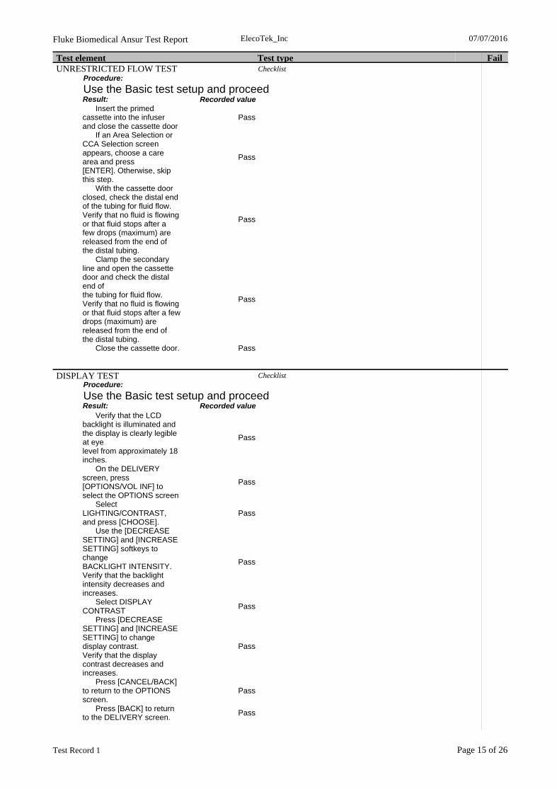
Test element Test type FailUNRESTRICTED FLOW TEST Checklist
Procedure:
Use the Basic test setup and proceedResult: Recorded value Insert the primed cassette into the infuser and close the cassette door
Pass
If an Area Selection or CCA Selection screen appears, choose a care area and press[ENTER]. Otherwise, skip this step.
Pass
With the cassette door closed, check the distal end of the tubing for fluid flow.Verify that no fluid is flowing or that fluid stops after a few drops (maximum) arereleased from the end of the distal tubing.
Pass
Clamp the secondary line and open the cassette door and check the distal end ofthe tubing for fluid flow. Verify that no fluid is flowing or that fluid stops after a fewdrops (maximum) are released from the end of the distal tubing.
Pass
Close the cassette door. Pass
DISPLAY TEST ChecklistProcedure:
Use the Basic test setup and proceedResult: Recorded value
Verify that the LCD backlight is illuminated and the display is clearly legible at eyelevel from approximately 18 inches.
Pass
On the DELIVERY screen, press [OPTIONS/VOL INF] to select the OPTIONS screen
Pass
Select LIGHTING/CONTRAST, and press [CHOOSE].
Pass
Use the [DECREASE SETTING] and [INCREASE SETTING] softkeys to changeBACKLIGHT INTENSITY. Verify that the backlight intensity decreases andincreases.
Pass
Select DISPLAY CONTRAST
Pass
Press [DECREASE SETTING] and [INCREASE SETTING] to change display contrast.Verify that the display contrast decreases and increases.
Pass
Press [CANCEL/BACK] to return to the OPTIONS screen.
Pass
Press [BACK] to return to the DELIVERY screen.
Pass
ElecoTek_Inc 07/07/2016
Test Record 1
Fluke Biomedical Ansur Test Report
Page 15 of 26

Test element Test type Fail
KEYPAD VERIFICATION/FUNCTIONAL TEST .1
Flow test
Procedure:
Use basic test setup.-While the infuser displays the DELIVERY screen, press [A] to select Line A.-Verify that the PROGRAM screen is displayed. Enter a rate of 123 mL/hr and VTBIof 4567.-Press [START]. If a CONFIRM PROGRAM? message appears, confirm that therate and VTBI are correct, and then press [YES].-Verify that fluid is pumping, the message PUMPING is displayed in the Line A statusbar, and the LED over Line A flashes.-Press [STOP].-Press and hold [BACKPRIME]. Verify that the BACKPRIMING and RELEASE-BACKPRIME TO STOP messages are displayed, and confirm that the infuser isactually backpriming.-Release the [BACKPRIME] softkey. Wait for cassette test to finish, before continuing to next step.-Press [START], and verify that Line A is pumping again.-Press [B].-Verify that PIGGYBACK is the displayed delivery mode. If necessary, change thedelivery mode by pressing [CHANGE MODE].
Configuration:
Channel selected Set flow rate[ml/h] Total volume[ml]Stop test when time
reached[hh:mm]Channel #1 SN #15931 123 4567 00:01
Result:Preset
Value Measurement Unit High Limit Low Limit Standard
IDA4 Plus #1 Channel #1 SN #15931
Average flow 123.00 120.88 ml/hUser
defined
Min instant flow 123.00 108.66 ml/hUser
defined
Max instant flow 123.00 128.16 ml/hUser
defined
Volume 4 567.00 2.10 mlUser
defined Overall percentage error - 1.7 %
Userdefined
ElecoTek_Inc 07/07/2016
Test Record 1
Fluke Biomedical Ansur Test Report
Page 16 of 26

Test element Test type Fail
Channel #1 SN #15931 Average flow vs Time
Time [HH:MM:SS]
00:00:00 00:00:20 00:00:40 00:01:00
ml/
h
0
20
40
60
80
100
120
Set flow rate
Channel #1 SN #15931 instant flow vs time
Time [HH:MM:SS]
00:00:00 00:00:20 00:00:40 00:01:00
ml/
h
0
20
40
60
80
100
120
140
Set flow rate
Channel #1 SN #15931 Trumpet Curve
Time [HH:MM:SS]
00:00:00 00:00:20 00:00:40 00:01:00
Err
or
[%]
- 100
- 90
- 80
- 70
- 60
- 50
- 40
- 30
- 20
- 10
0
Overall percentage error
ALARM LOUDNESS TEST ChecklistProcedure:
Use the Basic test setup and proceedResult: Recorded value
Press [A] to select Line A.
Pass
If the message CLEAR LINE A SETTINGS appears, press [YES].
Pass
Enter a rate of 400 mL/hr and VTBI of 1 mL
Pass
ElecoTek_Inc 07/07/2016
Test Record 1
Fluke Biomedical Ansur Test Report
Page 17 of 26

Test element Test type FailResult: Recorded value Press [START]. If a CONFIRM PROGRAM? message appears, confirm that therate and VTBI are correct, and then press [YES].
Pass
Verify that fluid is pumping, the message PUMPING is displayed in the Line A statusbar, and the LED above Line A flashes
Pass
Verify that the alarm sounds and the message LINE A VTBI COMPLETE appearswhen the dose has been delivered.
Pass
Turn the volume control knob on the back of the infuser clockwise andcounterclockwise. Verify that the alarm loudness changes.
Pass
Press the [SILENCE] key, and verify that the alarm is paused.
Pass
Press [STOP]. Pass
KEYPAD LOCKOUT SWITCH TEST ChecklistProcedure:
Use the Basic test setup and proceedResult: Recorded value
Press [A] to select Line A. If the message CLEAR LINE A SETTINGS appears, press[YES].
Pass
Enter a rate of 400 mL/hr and VTBI of 50 mL.
Pass
Press [START]. If a CONFIRM PROGRAM? message appears, confirm that therate and VTBI are correct, and then press [YES].
Pass
Verify that fluid is pumping, the message PUMPING is displayed in the Line A statusbar, and the LED above Line A flashes
Pass
Move the keypad lockout switch on the back of the infuser to the up (ON) positionto disable the keypad
Pass
Press any key except [STOP], and verify that an invalid key press audio alert isgenerated and the HARD LOCK ENABLED message is displayed. Confirm that theinfuser continues to operate.
Pass
Press [STOP]. Verify that an alarm sounds, the HARD LOCKOUT VIOLATIONmessage appears, and pumping stops.
Pass
ElecoTek_Inc 07/07/2016
Test Record 1
Fluke Biomedical Ansur Test Report
Page 18 of 26

Test element Test type FailResult: Recorded value Move the keypad lockout switch to the down (OFF) position. Verify that the HARDLOCKOUT VIOLATION message disappears and the alarm stops.
Pass
Press [START]. Pass Open the cassette door and verify that an alarm sounds and the DOOR OPEN WHILEPUMPING message is displayed.
Pass
Close the cassette door. Pass Press [NO] at the NEW PATIENT? or CLEAR SETTINGS? prompt.
Pass
Pass Pass Pass Pass
PROXIMAL OCCLUSION TEST Flow testProcedure:
-Press [START]. If a CONFIRM PROGRAM? message appears, confirm that therate and VTBI are correct, and then press [YES].-Verify that the LED above Line A flashes-After several pumping cycles, clamp the Line A tubing proximal to the cassette.-Verify that the PROXOCCL A/AIR message flashes and the alarm sounds beforethree pumping cycles are completed.-Press [SILENCE] and verify that the alarm stops while the message on the displaycontinues to flash.-Unclamp the proximal line and press [START]. Verify that pumping resumes.-Press [STOP].-Open the cassette door and remove the cassette.
Configuration:
Channel selected Set flow rate[ml/h] Total volume[ml]Stop test when time
reached[hh:mm]
Channel #1 SN #15931 400 50 00:03
Result:Preset
Value Measurement Unit High Limit Low Limit Standard
IDA4 Plus #1 Channel #1 SN #15931
Average flow 400.00 361.59 ml/hUser
defined
Min instant flow 400.00 16.21 ml/hUser
defined
Max instant flow 400.00 410.49 ml/hUser
defined
Volume 50.00 18.99 mlUser
defined Overall percentage error - 9.6 %
Userdefined
ElecoTek_Inc 07/07/2016
Test Record 1
Fluke Biomedical Ansur Test Report
Page 19 of 26

Test element Test type Fail
Channel #1 SN #15931 Average flow vs Time
Time [HH:MM:SS]
00:00:00 00:00:30 00:01:00 00:01:30 00:02:00 00:02:30 00:03:00
ml/
h
0
50
100
150
200
250
300
350
400
Set flow rate
Channel #1 SN #15931 instant flow vs time
Time [HH:MM:SS]
00:00:00 00:00:30 00:01:00 00:01:30 00:02:00 00:02:30 00:03:00
ml/
h
0
50
100
150
200
250
300
350
400
450
Set flow rate
Channel #1 SN #15931 Trumpet Curve
Time [HH:MM:SS]
00:00:00 00:00:20 00:00:40 00:01:00 00:01:20 00:01:40
Err
or
[%]
- 100
- 90
- 80
- 70
- 60
- 50
- 40
- 30
- 20
- 10
0
Overall percentage error
PROXIMAL AIR-IN-LINE TEST ChecklistProcedure:
Proximal Air-in-Line test uses the Proximal Air-in-Line test setup and the programming from the Proximal Occlusion test. (If performing this section as a standalone test, insert the test cassette prepared in Section 5.3.2.2, select Line A, and enter a rate of 400 mL/hr anda VTBI of 50 mL. Go to Step 4)Result: Recorded value
Insert the proximal test cassette into the infuser and close the cassette door.
Pass
ElecoTek_Inc 07/07/2016
Test Record 1
Fluke Biomedical Ansur Test Report
Page 20 of 26

Test element Test type FailResult: Recorded value If a NEW PATIENT? or CLEAR SETTINGS? message appears, press [NO].
Pass
Make a note of the Volume Infused (Vol Inf mL) displayed on the Main Deliveryscreen for Line A. You will need this value for Step 6.
Pass
Press [START]. If a CONFIRM PROGRAM? message appears, confirm that therate and VTBI are correct, and then press [YES].
Pass
Verify that fluid is pumping, the message PUMPING is displayed in the Line A statusbar, and the LED above Line A flashes.
Pass
Before 1 mL of fluid is delivered, verify that pumping stops, the alarm sounds, andthe N232 PROX AIR A, BACKPRIME message is flashing on the display.
Pass
Open the cassette door and remove the test cassette.
Pass
Pass
PROXIMAL AIR-IN-LINE TEST Flow testProcedure:
-Insert the proximal test cassette into the infuser and close the cassette door.-If a NEW PATIENT? or CLEAR SETTINGS? message appears, press [NO].-Make a note of the Volume Infused (Vol Inf mL) displayed on the Main Deliveryscreen for Line A. This value is for Step 6.-Press [START]. If a CONFIRM PROGRAM? message appears, confirm that therate and VTBI are correct, and then press [YES].-Verify that fluid is pumping, the message PUMPING is displayed in the Line A statusbar, and the LED above Line A flashes.-Before 1 mL of fluid is delivered, verify that pumping stops, the alarm sounds, andthe N232 PROX AIR A, BACKPRIME message is flashing on the display.-Open the cassette door and remove the test cassette.
Configuration:
Channel selected Set flow rate[ml/h] Total volume[ml]Stop test when time
reached[hh:mm]
Channel #1 SN #15931 400 50 00:03
Result:Preset
Value Measurement Unit High Limit Low Limit Standard
IDA4 Plus #1 Channel #1 SN #15931
Average flow 400.00 397.00 ml/hUser
defined
Min instant flow 400.00 175.66 ml/hUser
defined
Max instant flow 400.00 410.99 ml/hUser
defined
Volume 50.00 20.11 mlUser
defined Overall percentage error - 0.8 %
Userdefined
ElecoTek_Inc 07/07/2016
Test Record 1
Fluke Biomedical Ansur Test Report
Page 21 of 26

Test element Test type Fail
Channel #1 SN #15931 Average flow vs Time
Time [HH:MM:SS]
00:00:00 00:00:30 00:01:00 00:01:30 00:02:00 00:02:30 00:03:00
ml/
h
0
50
100
150
200
250
300
350
400
450
Set flow rate
Channel #1 SN #15931 instant flow vs time
Time [HH:MM:SS]
00:00:00 00:00:30 00:01:00 00:01:30 00:02:00 00:02:30 00:03:00
ml/
h
0
50
100
150
200
250
300
350
400
450
Set flow rate
Channel #1 SN #15931 Trumpet Curve
Time [HH:MM:SS]
00:00:00 00:00:20 00:00:40 00:01:00 00:01:20 00:01:40
Err
or
[%]
- 100
- 90
- 80
- 70
- 60
- 50
- 40
- 30
- 20
- 10
0
Overall percentage error
DISTAL OCCLUSION TEST .1 ChecklistProcedure:
Use basic test setupResult: Recorded value
Insert the cassette from the Basic test setup into the infuser and close the cassettedoor. The infuser will proceed with the cassette test.
Pass
ElecoTek_Inc 07/07/2016
Test Record 1
Fluke Biomedical Ansur Test Report
Page 22 of 26
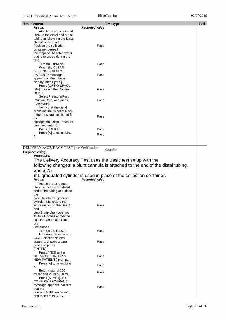
Test element Test type FailResult: Recorded value Attach the stopcock and DPM to the distal end of the tubing as shown in the DistalOcclusion test setup. Position the collection container beneaththe stopcock to catch water that is released during the test.
Pass
Turn the DPM on. Pass When the CLEAR SETTINGS? or NEW PATIENT? message appears on the infuserdisplay, press [YES].
Pass
Press [OPTIONS/VOL INF] to select the Options screen.
Pass
Select Pressure/Post Infusion Rate, and press [CHOOSE].
Pass
Verify that the distal pressure limit is set at 6 psi. If the pressure limit is not 6 psi,highlight the Distal Pressure Limit and enter 6.
Pass
Press [ENTER]. Pass Press [A] to select Line A.
Pass
DELIVERY ACCURACY TEST (for Verification Purposes only) .1
Checklist
Procedure:
The Delivery Accuracy Test uses the Basic test setup with thefollowing changes: a blunt cannula is attached to the end of the distal tubing, and a 25mL graduated cylinder is used in place of the collection container. Result: Recorded value
Attach the 18-gauge blunt cannula to the distal end of the tubing and place thecannula into the graduated cylinder. Make sure the score marks on the Line A andLine B drip chambers are 12 to 24 inches above the cassette and that all lines areunclamped
Pass
Turn on the infuser. Pass If an Area Selection or CCA Selection screen appears, choose a care area and press[ENTER].
Pass
Press [YES] at the CLEAR SETTINGS? or NEW PATIENT? prompt.
Pass
Press [A] to select Line A.
Pass
Enter a rate of 200 mL/hr and VTBI of 10 mL.
Pass
Press [START]. If a CONFIRM PROGRAM? message appears, confirm that therate and VTBI are correct, and then press [YES].
Pass
ElecoTek_Inc 07/07/2016
Test Record 1
Fluke Biomedical Ansur Test Report
Page 23 of 26

Test element Test type FailResult: Recorded value Verify that fluid is pumping, the message PUMPING is displayed in the Line A statusbar, and the LED over Line A flashes.
Pass
Press [B] to select Line B.
Pass
Verify that Piggyback delivery mode is selected. If necessary, press[CHANGE MODE] to change the delivery mode.
Pass
Enter a rate of 200 mL/hr and a VTBI of 10 mL.
Pass
Press [START]. If a CONFIRM PROGRAM? message appears, confirm that therate and VTBI are correct, and then press [YES].
Pass
Verify that fluid is pumping, the message PUMPING is displayed in the Line B statusbar, and the LED over Line B flashes. Line A will be stopped (DELAYED) while Line B is pumping, and willresume pumping when Line B delivery is complete.
Pass
When total delivery is complete on Line A, verify that the KVO message flashes onthe display and an audible alarm sounds.
Pass
Press [STOP] and verify that the volume delivered into the graduated cylinder is 20mL +/- 1 mL. The pumping chamber in a test cassette can become fatigued afterrepeated tests are run. If an infuser fails the delivery accuracy test, run thetest again with a new primary administration set, to ensure that the issue iswith the infuser, not the test setup.
Pass
Protective Earth Resistance Protective Earth ResistanceProcedure:
If the infuser does not have a ground test screw/post, connect theanalyzer ground lead to one of the screws that secures the power cord retainer.Configuration
Test Current: LowResult: Value Unit High limit Low limit Standard
PE Resistance1 0.168 Ohm 0.2 User defined
Enclosure Leakage Current Enclosure Leakage CurrentConfiguration
Unused Applied Parts: Floating
Normal ConditionEnclosure Leakage CurrentNormal Condition
Result: Value Unit High limit Low limit Standard
Normal Condition 1.4 uAAC+DC 100 0 User defined
ElecoTek_Inc 07/07/2016
Test Record 1
Fluke Biomedical Ansur Test Report
Page 24 of 26

Test element Test type Fail
Open NeutralEnclosure Leakage CurrentOpen Neutral
Result: Value Unit High limit Low limit Standard Open Neutral 1.4 uAAC+DC 300 0 User defined
Open EarthEnclosure Leakage CurrentOpen Earth
Result: Value Unit High limit Low limit Standard Open Earth 21.2 uAAC+DC 300 0 User defined
Normal Condition, Reversed mainsEnclosure Leakage CurrentNormal Condition, Reversed mains
Result: Value Unit High limit Low limit Standard Normal Condition, Reversed mains
1.4 uAAC+DC 100 0 User defined
Open Neutral, Reversed MainsEnclosure Leakage CurrentOpen Neutral, Reversed Mains
Result: Value Unit High limit Low limit Standard
Open Neutral, Reversed Mains
1.4 uAAC+DC 300 0 User defined
Open Earth, Reversed MainsEnclosure Leakage CurrentOpen Earth, Reversed Mains
Result: Value Unit High limit Low limit Standard
Open Earth, Reversed Mains
21.8 uAAC+DC 300 0 User defined
Earth Leakage Current Earth Leakage CurrentConfiguration
Unused Applied Parts: Floating
Normal ConditionEarth Leakage CurrentNormal Condition
Result: Value Unit High limit Low limit Standard
Normal Condition 23.4 uAAC+DC 500 0 User defined
Open NeutralEarth Leakage CurrentOpen Neutral
Result: Value Unit High limit Low limit Standard
Open Neutral 37.1 uAAC+DC 1000 0 User defined
Normal Condition, Reversed mainsEarth Leakage CurrentNormal Condition, Reversed mains
Result: Value Unit High limit Low limit Standard
Normal Condition, Reversed mains
25.6 uAAC+DC 500 0 User defined
Open Neutral, Reversed MainsEarth Leakage CurrentOpen Neutral, Reversed Mains
Result: Value Unit High limit Low limit Standard
Open Neutral, Reversed Mains
37.1 uAAC+DC 1000 0 User defined
END OF THE PVT ChecklistProcedure:
If the infuser passed all performance verification tests, follow these instructions to clearall programming and prepare the device to be put back into service:Result: Recorded value
Turn on the infuser. Pass
ElecoTek_Inc 07/07/2016
Test Record 1
Fluke Biomedical Ansur Test Report
Page 25 of 26
Test element Test type FailResult: Recorded value If an Area Selection or CCA Selection screen appears, choose a care area and press[ENTER].
Pass
In response to the NEW PATIENT? or CLEAR SETTINGS? prompt, press [YES].
Pass
Remove the cassette and close the cassette door.
Pass
Turn off the infuser. Pass Make sure the keypad lockout switch on the back of the infuser is in the DOWNposition (lockout disabled).
Pass
Return the infuser to service.
Pass
ElecoTek_Inc 07/07/2016
Test Record 1
Fluke Biomedical Ansur Test Report
Page 26 of 26