Embed Size (px)
Citation preview

BIM-MEPAUS SPECIFICATION
Air handling system metal ductwork
Issued By: BIM-MEPAUS
30 Cromwell Street, Burwood 3205 VIC Australia
Revision: WIP REV D
Date October 2016

BIM-MEPAUS Specification
Air handling system metal ductwork
BIM-MEPAUS Page 2 June 2016
Acknowledgements BIM-MEPAUS acknowledges the contributions of the following organisations involved in the development of this
document:
BIM-MEPAUS acknowledges the contributions of those organisations involved in the development and review of this
specification including principal contributors:
Arups
A.G. Coombs
BSA
D&E Air conditioning
Ductmakers
Kavanagh Industries
TinMen SA
Triple M Mechanical
O’Connors
RolaDuct
Watson Fitzgerald & Associates
Norman Disney & Young
Formatting conventions
The following table provides the text formats used in BIM-MEPAUS documentation and their application:
Text Type Example Indicates
Italicized text BIM Execution Plan The generic title for a type of document.
Bold italicised text BIM-MEPAUS Specification The name of a referenced document.
Dark red text LOD First reference to a term or abbreviation that is
defined in the website glossary under Practices.
Blue text www.bimmepaus.com.au Hyperlink / web-link.
Blue italicised text Explanatory notes Explanatory notes or reference information.
Green text Future development Sections or documents that are still under
development by BIM-MEPAUS.
Keeping BIM-MEPAUS up-to-date
BIM-MEPAUS specifications, templates and content are updated to reflect changes in legislation, technology and
industry practice. Feedback and suggestions are welcome and can be made via the BIM-MEPAUS website. Updates
are managed and delivered via the BIM-MEPAUS website.
Liability Disclaimer BIM-MEPAUS makes no warranty, expressed or implied, including but not limited to any implied warranties of
merchantability and fitness for a particular purpose, nor assume any legal liability or responsibility for the accuracy,
completeness, or usefulness of the information in this document.
In no event shall BIM-MEPAUS or its agents be liable for damages or losses resulting from the use of, or reliance on
the information provided in this document.
COPYRIGHT © BIM-MEPAUS
All rights reserved.

BIM-MEPAUS Specification
Air handling system metal ductwork
BIM-MEPAUS Page 3 June 2016
Table of Contents
1 INTRODUCTION .............................................................................................................. 1
1.1 Scope .......................................................................................................................................... 1
1.2 References ................................................................................................................................. 1
1.3 Objectives ................................................................................................................................... 1
2 DUCTWORK STANDARDS ............................................................................................. 2
3 DUCTWORK MODELS .................................................................................................... 3
3.1 Model workflow ........................................................................................................................... 3
3.2 System schematics ..................................................................................................................... 3
3.3 Services coordination plan.......................................................................................................... 3
3.4 Design ductwork model .............................................................................................................. 4
3.5 Construction ductwork model ..................................................................................................... 4
3.6 As-built ductwork model.............................................................................................................. 4
4 DUCTWORK SPECIFICATIONS ...................................................................................... 5
4.1 Ductwork standards .................................................................................................................... 5
4.2 Ductwork sizes ............................................................................................................................ 5
4.3 Ductwork materials ..................................................................................................................... 5
4.4 Pressure ratings .......................................................................................................................... 5
4.5 Design parameters ..................................................................................................................... 5
4.6 Air leakage .................................................................................................................................. 5
5 SYSTEMS, SERVICES AND SPECIFICATIONS ............................................................. 6
5.1 Systems, services and specifications ......................................................................................... 6
5.2 Service types .............................................................................................................................. 6
6 DUCTWORK SYSTEMS .................................................................................................. 7
7 DUCTWORK SPECIFICATIONS ...................................................................................... 8
8 DUCTWORK SERVICES ................................................................................................. 9
9 RECTANGULAR DUCTWORK .......................................................................................10
9.1 General ..................................................................................................................................... 10
9.2 Standard connectors ................................................................................................................. 10
9.3 Internal linings ........................................................................................................................... 10
9.4 Rectangular straights ................................................................................................................ 10
9.5 Rectangular fittings ................................................................................................................... 10
9.6 Rectangular accessories .......................................................................................................... 10
10 ROUND DUCTWORK .....................................................................................................11
10.1 General ..................................................................................................................................... 11
10.2 Sizes ......................................................................................................................................... 11
10.3 Straights .................................................................................................................................... 11
10.4 Fittings ...................................................................................................................................... 11

BIM-MEPAUS Specification
Air handling system metal ductwork
BIM-MEPAUS Page 4 June 2016
10.5 Accessories .............................................................................................................................. 11
11 OVAL DUCTWORK.........................................................................................................12
11.1 General ..................................................................................................................................... 12
11.2 Straights .................................................................................................................................... 12
11.3 Fittings ...................................................................................................................................... 13
11.4 Accessories .............................................................................................................................. 13
12 DUCTWORK SHARED PARAMETERS ..........................................................................14
ANNEXURE A – Ductwork legend and annotation
ANNEXURE B – Rectangular duct standard templates
ANNEXURE C – Round duct standard templates
ANNEXURE D – Oval duct standard templates
ANNEXURE E – CID Standard option settings

BIM-MEPAUS Specification
Air handling system metal ductwork
BIM-MEPAUS Page 1 June 2016
1 INTRODUCTION
1.1 Scope
This document sets out the BIM-MEPAUS specification for air handling system metal ductwork comprising:
Rectangular sheet metal ductwork
Round spiral wound metal ductwork
Oval spiral wound metal ductwork.
1.2 References
This specification should be read in conjunction with the following documents:
BIM-MEPAUS Airside systems, plant and equipment schedule – this Excel based schedule provides
the complete listing for all ductwork systems, plant and equipment names as well as the system colour
schema.
BIM-MEPAUS Master shared parameter schedule – this document provides the reference source for all
shared parameter names used within the BIM-MEPAUS generic design and MCM models – this Excel
formatted schedule also provides the Revit classification for each parameter and its associated GUID.
BIM-MEPAUS Ductwork lining and insulation wrap specification – this specification sets out the
technical specification and modelling workflows for ductwork linings and insulation wraps.
BIM-MEPAUS Damper specification – this specification sets out the technical specification and modelling
workflows for ductwork general purpose, smoke and fire dampers.
BIM-MEPAUS Flexible ductwork specification – this specification sets out the technical specification and
modelling workflows for flexible ductwork.
BIM-MEPAUS Ductwork fire resistance paints, wraps and sprays specification – this specification sets
out the technical specification and modelling workflows for ductwork fire resistant paints, wraps and sprays.
These documents can be accessed through the BIM-MEPAUS website.
1.3 Objectives
Benefits sought through the development and implementation of the standard include:
A structured approach to the speciation and modelling of ductwork systems, services and specifications;
Reliable Design-to-Fabrication and Design-to-Commissioned As-Built workflows; and
Industry standardisation delivering improved supply chain efficiency, reduced project risks and cost.

BIM-MEPAUS Specification
Air handling system metal ductwork
BIM-MEPAUS Page 2 June 2016
2 DUCTWORK STANDARDS
There are a number of requirements in the National Construction Code and referenced standards that relate to
sheet metal ductwork design, fabrication and installation.
Standards considered relevant to mechanical services ductwork include:
General Requirements
NCC/ BCA : National Construction Code / Building Code of Australia
AS 1074.4 : Structural Design Actions Part 4 Earthquake Actions in Australia
Ductwork
AS 4254.1 - 2012 : Ductwork for air-handling systems in buildings - Part 1: Flexible duct
AS 4254.2 - 2012 : Ductwork for air-handling systems in buildings - Part 2: Rigid duct
AS 1668.1 - 2015 : The use of ventilation and airconditioning in buildings – Part 1: Fire and Smoke
Control in multi-compartment buildings
AS 1668.2 - 2012 : The use of ventilation and airconditioning in buildings – Part 2: Mechanical
Ventilation in buildings
Fire Dampers
AS 1682.1 - 2015 : Fire, Smoke and Air Dampers Part 1: Specification
AS 1682.2 - 2015 : Fire, Smoke and Air Damper Part 2: Installation
Insulation
AS 4426 - 1997 : Thermal Insulation of pipework, ductwork and equipment – Selection,
installation and finish
AS 4508 - 1999 : Thermal resistance of insulation for ductwork used in building air conditioning
Testing
AS 1530.3 - 1999 : Methods of fire tests on building materials, components and structures -
Simultaneous determination of ignitability, flame propagation, heat release and
smoke release
AS/NZS 4859.1 - 2002 : Materials for the thermal insulation of buildings - General criteria and technical
provisions
UL 181 : Factory-Made Air Ducts and Air Connectors.
In addition to the above standards, this specification incorporates the Insulation Council of Australia and New
Zealand’s recommended specifications for ductwork internal linings and insulation wraps developed in conjunction
with BIM-MEPAUS.

BIM-MEPAUS Specification
Air handling system metal ductwork
BIM-MEPAUS Page 3 June 2016
3 DUCTWORK MODELS
3.1 Model workflow
One of the principle aims of BIM-MEPAUS is to enable efficient Design to As-Built BIM workflows that see the
design model progressively developed through the design, virtual build and construction process to ultimately
deliver a completed As-built Model to the client.
The standard also supports the Design to Fabrication workflow that sees the Revit ductwork construction model
converted to either a Fabrication ITM Model or exported directly to MAJ file format for pricing and manufacture.
A key step in both workflows is the virtual build that sees the design ductwork services developed to a fully
coordinated constructible layout prior to issue for fabrication. This construction model is also used to drive site
layout, procurement and installation scheduling activities as well as commissioning BIM to field processes.
3.2 System schematics
Prior to modelling commencing, ducting system design should start with the development of the system schematics,
compartmentation and functional control strategies. These are key to conveying the design intent and are also the
starting point for the modelling of the ductwork layouts.
Best practice air side schematics convey the system architecture and include:
Building Levels / Compartmentation
Smoke and fire rated walls
Duct sizes and design air flows
Monitoring and control strategies
Pressure Zones within the system.
The BIM-MEPAUS template is not intended to generate the schematic from the design model and it is envisaged that
schematics will continue to be prepared in AutoCAD for the foreseeable future.
3.3 Services coordination plan
Prior to modelling commencing, the services coordination plan should be documented using constructible level
ductwork and piping elements and fittings to resolve:
The services zones
The clash avoidance rules that govern which services give way under various clash scenarios.
The services coordination plan should be included in all services packages and form a key deliverable of schematic
design phase independent of any LOD definition deliverable.
BIM As - Built
Model LOD 500 BIM Design Model
LOD 100 - 300 BIM Construction
Model LOD 400
CAM Fabrication
Model LOD 400
Virtual
Build
Fabrication Export

BIM-MEPAUS Specification
Air handling system metal ductwork
BIM-MEPAUS Page 4 June 2016
3.4 Design ductwork model
The BIM-MEPAUS Revit® Template add-in allows engineers and modellers to design and specify systems using
constructible Revit family based ducting services that incorporate relevant Australian standards and industry based
manufacturing practices.
BIM-MEPAUS design ductwork models nominate both the system and required ductwork service and specification
and are typically modelled in BIM-MEPAUS constructible Revit families that are built to match the corresponding BIM-
MEPAUS Revit Fabrication Parts.
The use of BIM-MEPAUS constructible services allows a range of engineering calculations and checks to be
completed with greater accuracy. The aim is to support the following engineering tasks:
System air flow rate calculations
Air velocity checks
Estimated static pressure losses
System specification checks.
3.5 Construction ductwork model
BIM-MEPAUS construction models provide construction level detailing using Revit Fabrication Parts and
manufacturer certified content.
The virtual build of the design model to create the LOD 400 construction model delivers a model that is fully
designated in terms of system type, service and specification. When read in conjunction with the duct fabricator’s
manufacturing specifications the model should provide sufficient detail for approval submissions.
The virtual build typically involves a number of tasks:
Changing-out of the design content with manufacturer’s certified content for end of line plant and
equipment such as fan coil units and fans, etc
Conversion of the ductwork system modelled in Revit family based service into Revit Fabrication Parts
based services.
Value Engineering to optimise the most cost effective service and layout within specification
Checking costs against original estimates and/or budget
Final services coordination and routing
System engineering checks including pressure loss and ductwork leakage calculations for fan selections
Piece marking and fabrication.
Once the construction model is finalized and approved, the Revit Fabrication Parts ductwork model can be exported
in MAJ file format to ductwork manufacturers or converted to a Fabrication model for further development including:
Ductwork reinforcement optimisation
Value engineering based on accurate Fabrication ESTmep costing data.
3.6 As-built ductwork model
Once the installation is completed any site changes can be used to finalise the As Built model for provision to the
client.

BIM-MEPAUS Specification
Air handling system metal ductwork
BIM-MEPAUS Page 5 June 2016
4 DUCTWORK SPECIFICATIONS
4.1 Ductwork standards
BIM-MEPAUS sheet metal ductwork services are generally based on AS 4254.2 - 2012 and AS 1668.1 - 2015
4.2 Ductwork sizes
All ductwork sizes are based on hard metric and are nominated as Top Plan View - Width X Depth X Length.
BIM-MEPAUS ductwork dimensions are based on sheet metal size that for plain or externally insulated ductwork is
airway size. For internally lined duct it is necessary to deduct the lining thickness to arrive at the airway size.
4.3 Ductwork materials
Galvanised sheet metal is based on G2 carbon steel with GZ-275 hot dip galvanised finish with the following gauges
used 0.6mm, 0.8mm, 1.0mm, 1.2mm, 1.6mm and 2.0mm.
Perforated metal is based on G2 carbon steel with GZ-275 hot dip galvanised finish 0.6mm gauge 2.33mm hole
diameter providing a percentage open area of 11%.
Alterative metal specifications comprise stainless steel 304L, stainless steel 316L and aluminum.
4.4 Pressure ratings
Australian Standard AS 4252 Ductwork for air handling systems in buildings lists a series of pressure classes from
125Pa through to 2500Pa. BIM-MEPAUS uses a simplified pressure rating framework:
Designation Pressure Rating
LP ≤ 500 Pa
HP ≤ 1000Pa
For pressures higher than 1000Pa, designate ductwork pressure in accordance with AS4254 - 2012 Table 2.2.1
Ductwork Pressure Rating Schedule.
4.5 Design parameters
The following metric design units and coefficients are used:
Airflow L/s
Airflow Velocity m/s
Loss Coefficient Kv values based on ASHRAE Data
Through the use of these parameters, Revit is able to provide air flows and estimated system pressure loses.
4.6 Air leakage
Air leakage must be accounted for when determining the required fan capacity.
For a given ductwork fabrication standard, air leakage is a function of system operating pressure and system surface
area. The air leakage calculation methods and acceptance criteria provided by ASHRAE, SMACNA or BSRIA codes
are based on pressure and system surface area, not system airflow and are the preferred basis for system leakage
calculations, testing and acceptance.
All BIM-MEPAUS ductwork specifications incorporate Class A sealing.

BIM-MEPAUS Specification
Air handling system metal ductwork
BIM-MEPAUS Page 6 June 2016
5 SYSTEMS, SERVICES AND SPECIFICATIONS
5.1 Systems, services and specifications
A key feature of the BIM-MEPAUS approach to ductwork modelling is the use of defined ductwork systems,
services and specifications. This approach draws from both the Revit approach to system modelling and the
Fabrication approach to shop drawing and manufacturing and is key to realising the full potential of constructible
Revit to Fabrication workflows:
Systems define the type of reticulation system: Supply Air System, Smoke Spill System, Clean Air System, etc.
Services set the ductwork type and routing preferences for a particular system.
Specifications detail the fabrication standards and details for the ductwork service.
In BIM-MEPAUS the system and service must be selected to model the system and specify the required ducting type
ie Toilet Exhaust – Low Pressure.
Within AS 4254.2 2012 it is permitted to optimize the ductwork sheet metal specification gauge and reinforcing
combination to achieve compliance through either deemed to satisfy or evidence based compliance methods. The
details in relation to reinforcement methods should be determined from the ductwork manufacturer’s specifications.
5.2 Service types
There are two types of ductwork services:
Design services provided with the BIM-MEPAUS Revit MEP template add-in using Revit Families
Fabricator services built from BIM-MEPAUS Revit Fabrication Parts.
The BIM-MEPAUS ductwork service naming convention syntax comprises:
Author_System_Service
Design Services
The BIM-MEPAUS template add-in provides one or more defined AS 4254.2 compliant family based services for
each system type.
For example, for supply air there are two standard BIM-MEPAUS services:
BMA_SA_LP
BMA_SA_HP
The full range of systems and services available in the template are listed in the BIM-MEPAUS Airside Systems,
Plant and Equipment Schedule.
Fabricator Services
Fabricator services are fully routed BIM-MEPAUS Revit Fabrication Part based services with enhanced features that
support shop drawing modelling and MAJ file format conversion.
Manufacturer Name_SA_LP
Manufacturer Name_SA_HP

BIM-MEPAUS Specification
Air handling system metal ductwork
BIM-MEPAUS Page 7 June 2016
6 DUCTWORK SYSTEMS
BIM-MEPAUS provides a naming scheme for ductwork systems based on Australian standards and industry practice.
The following table lists the foundation systems provided.
Designation System Colour Colour Name
CA Clean Air Dark Turquoise
CE Car Park Exhaust Coral
EA Exhaust Air - General Orange
HE Hazardous Exhaust Pale Violet Red
KE Kitchen Exhaust Pink
MA Make-up Air Light Green
OA Outside Air Light Green
PA Pressurisation Air (Smoke Control) Pale Green
RA Return Air Light Pink
SA Supply Air Light Blue
SE Smoke Exhaust Red
TA Transfer Air Yellow Green
TE Toilet Exhaust Light Salmon
The BIM-MEPAUS Airside systems, plant and equipment schedule provides the complete listing of systems and
their associated colour shading and line type RGB colour code.
Design Notes
I. Pressurisation air systems relate to AS 1668 zone smoke control systems – most commonly
these are stair pressurization systems but can serve other spaces and forms of exit paths that
are required to be positively pressurised in fire mode.
II. Refer to the BIM-MEPAUS System colour scheme
System Characteristic Colour Spectrum
Unconditioned outside air systems Turquoise – Green - Lime
Conditioned air systems Violet – Blue - Cobalt
Conditioned return air systems Light reds
Non Hazardous exhaust systems Amber - Orange
Smoke Exhaust systems Reds
Kitchen and hazardous exhaust systems Crimson – Magenta - Violet
For accurate colour renditions refer to HTML colour names.

BIM-MEPAUS Specification
Air handling system metal ductwork
BIM-MEPAUS Page 8 June 2016
7 DUCTWORK SPECIFICATIONS
Ductwork services are based on a limited range of ductwork specifications in order to reduce the complexity of
modelling and manufacturing workflows and associated embedded cost burdens.
Galvanised ductwork (Class A Sealed)
Service Designation Service Description
LP Low Pressure ≤ 500 Pa
HP High Pressure ≤ 1000 Pa
KE Kitchen Exhaust (LP) Minimum 1.2mm Gauge
CA Clean Room (HP) , Factory cleaned and sealed
prior to delivery
FR Fire Resistant (Low Pressure), strengthened for
fire wrap /spray
SD Sub duct
Stainless steel and aluminum ductwork
Service Designation Service Description
304 Stainless Steel 304L (Low Pressure)
KE304 Kitchen Exhaust Stainless Steel 304L min
thickness 0.9mm (Low Pressure)
316 Stainless Steel 316L (Low Pressure)
ALU Aluminum (Low Pressure)
Commentary
I. The majority of services use low pressure Class A sealed ductwork. Class A sealing has been
traditionally provided only for toilet exhaust, clean air and high pressure systems, however the
sealing of the longitudinal seam has been shown to be effective in reducing total system leakage,
an important determinate in overall system energy use, as well as greatly simplifying modelling
and manufacturing standards and processes.
II. Stainless steel ductwork is generally specified as 304L being the more economical of the two
stainless steel options. For harsh environments such as coastal locations, marine grade 316L
stainless may be specified due to its substantially better corrosion resistance. The cost difference
between 304L and 316L is typically of the order of 25-30%.
BIM-MEPAUS Specification
Air handling system metal ductwork
BIM-MEPAUS Page 9 June 2016
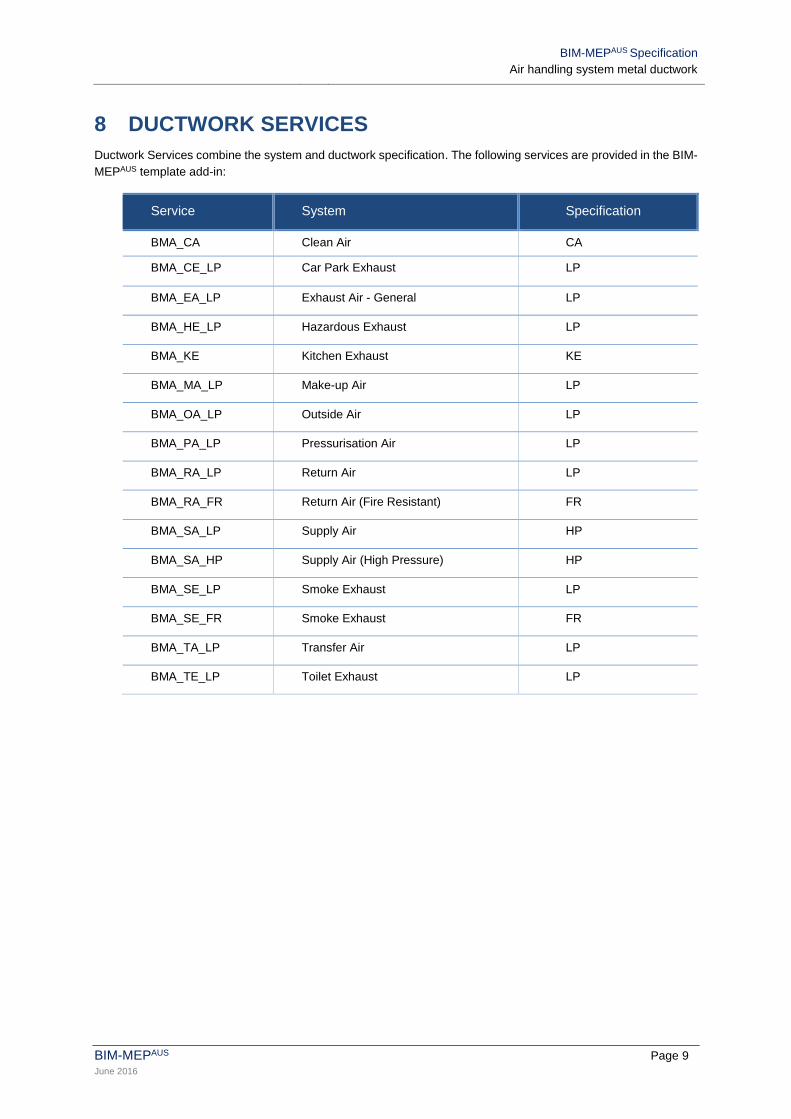
8 DUCTWORK SERVICES
Ductwork Services combine the system and ductwork specification. The following services are provided in the BIM-
MEPAUS template add-in:
Service System Specification
BMA_CA Clean Air CA
BMA_CE_LP Car Park Exhaust LP
BMA_EA_LP Exhaust Air - General LP
BMA_HE_LP Hazardous Exhaust LP
BMA_KE Kitchen Exhaust KE
BMA_MA_LP Make-up Air LP
BMA_OA_LP Outside Air LP
BMA_PA_LP Pressurisation Air LP
BMA_RA_LP Return Air LP
BMA_RA_FR Return Air (Fire Resistant) FR
BMA_SA_LP Supply Air HP
BMA_SA_HP Supply Air (High Pressure) HP
BMA_SE_LP Smoke Exhaust LP
BMA_SE_FR Smoke Exhaust FR
BMA_TA_LP Transfer Air LP
BMA_TE_LP Toilet Exhaust LP

BIM-MEPAUS Specification
Air handling system metal ductwork
BIM-MEPAUS Page 10 June 2016
9 RECTANGULAR DUCTWORK
9.1 General
Annexure B provides the rectangular ductwork templates for standard straights and fittings including the Fabrication
CID upon which the shape is based.
9.2 Standard connectors
Standard connectors are based on the use of the 35mm Transverse Duct Frame: 35 TDF.
Non-standard connectors include:
Loose Frame / Angle
Drive Cleat.
All connector designations are based on C1, C2 & C3 as detailed on the CID.
9.3 Internal linings
Standard internal insulation/acoustic linings are scheduled as
R1.2 (50mm)
R2.0 (75mm)
R3.0 (100mm).
For projects that have used a performance based solution to achieving the building energy efficiency requirements
a non-standard insulation/acoustic lining option has been provided:
R0.7 (25mm).
Refer to the BIM-MEPAUS Ductwork linings and insulation wrap specification for further details.
9.4 Rectangular straights
Ductwork straight lengths are determined by the combination of coil width, connector type and internal lining
thickness.
The standard coil width and connector forming the basis of the straights is 1500mm with 35mm TDF.
All straights are based on the Fabrication shape file CID 866.
Stepped frame straight lengths are defined for lining thicknesses and 35TDF connectors
9.5 Rectangular fittings
All fittings are referenced to a unique Fabrication CID shape that assures the design model is constructible.
The dimensions on the template are referenced to the CID dimensions and are shown in top plan view.
9.6 Rectangular accessories
Accessories comprise components that are typically added to ductwork and include access panels, doors and
spigots. Accessories are typically supplied as components to the ductwork manufacturer.
All accessories are referenced to unique Fabrication CID components that assures the design model is
constructible.

BIM-MEPAUS Specification
Air handling system metal ductwork
BIM-MEPAUS Page 11 June 2016
10 ROUND DUCTWORK
10.1 General
All round ductwork dimensions are based on sheet metal size.
All round duct is rated as high pressure due to the material thickness being determined by rigidity and manufacturing
requirements. The standard gauges within the specifications are:
0.6mm up to DIA 500
0.8mm DIA 550mm up to 900mm
1.0mm DIA 950mm up to 1200mm
1.2mm DIA 1300mm up to 1500mm
All ductwork services, whether high or low pressure, incorporate the same round duct specification with the
exception of KE which has a minimum gauge of 1.2mm.
Internally lined ductwork is generally double skinned construction with 32kg/m3 polyester insulation. Internal lining
options are generally limited to R1.2 (50mm) or R2.0 (75mm).
10.2 Sizes
Round ductwork design services are based on a rationalised set of hard metric standard sizes.
The following standard round duct sizes are provided:
150mm 350mm 550mm 750mm 950mm 1300mm
200mm 400mm 600mm 800mm 1000mm 1400mm
250mm 450mm 650mm 850mm 1100mm 1500mm
300mm 500mm 700mm 900mm 1200mm 1600mm.
Standard Round straight lengths are nominated as 3.0m for material handling purposes with a maximum practical
length generally considered to be 6m.
10.3 Straights
All straights are based on the Fabrication shape file CID 40 and generally comprise spiral wound construction.
10.4 Fittings
All fittings are referenced to unique Fabrication CID shapes that assure the design model is constructible.
10.5 Accessories
Accessories comprise manufactured components that are typically added to ductwork and include access panels
and spigots.

BIM-MEPAUS Specification
Air handling system metal ductwork
BIM-MEPAUS Page 12 June 2016
11 OVAL DUCTWORK
11.1 General
All oval ductwork dimensions are based on sheet metal size.
All oval duct is rated as high pressure due to the material thickness being determined by rigidity and manufacturing
requirements. Standard gauges for the round tube stock used to form the oval duct are:
0.6mm up to DIA 500
0.8mm DIA 550mm up to 900mm
1.0mm DIA 950mm and above
All Ductwork services, whether high or low pressure, incorporate the same oval duct specification with the exception
of KE which has a minimum gauge of 1.2mm.
Internally lined ductwork is generally double skinned duct with 32kg/m3 polyester insulation. Internal lining options
are generally limited to R1.2 (50mm).
Oval ductwork design services are based on a nominal set of dimensions due to the majority of Australian
manufacturer’s using imperial round tube sizes and imperial oval duct forming machines. The standard sizes are
limited to aspect ratios between 1:2 and 1:4.
Ductwork widths are nominal sizes only rounded to the nearest 5mm and the standard range of sizes are listed in
the templates. Nominal dimensions are:
150 x 500mm 300 x 635mm 400 x 890mm 500 x 1070mm
x 555mm x 710mm x 965mm x 1145mm
x 635mm x 790mm x 1040mm x 1225mm
x 865mm x 1120mm x 1305mm
200 x 535mm x 940mm x 1200mm x 1390mm
x 610mm x 1015mm x 1295mm x 1470mm
x 685mm x 1100mm x 1370mm x 1550mm
x 760mm x 1195mm x 1450mm x 1625mm
x 840mm x 1270mm x 1525mm x 1700mm
250 x 585mm 350 x 760mm 450 x 940mm 600 x 1250mm
x 660mm x 840mm x 1015mm x 1325mm
x 735mm x 915mm x 1090mm x 1405mm
x 810mm x 990mm x 1175mm x 1490mm
x 890mm x 1070mm x 1250mm x 1565mm
x 965mm x 1150mm x 1345mm x 1645mm
x 1050mm x 1245mm x 1420mm x 1720mm
x 1320mm x 1500mm x 1800mm
x 1575mm x 2000mm
Oval straight lengths can generally be manufactured to any length up to and including 3.6m.
11.2 Straights
All straights are based on the Fabrication shape file CID 40 and generally comprise spiral wound construction.

BIM-MEPAUS Specification
Air handling system metal ductwork
BIM-MEPAUS Page 13 June 2016
11.3 Fittings
A limited range of fittings are provided in Oval Duct and are referenced to a unique Fabrication CID shapes that
assure the design model is constructible.
11.4 Accessories
Accessories comprise manufactured components that are typically added to ductwork and include access panels
and spigots.

BIM-MEPAUS Specification
Air handling system metal ductwork
BIM-MEPAUS Page 14 June 2016
12 DUCTWORK SHARED PARAMETERS
The ductwork shared parameters are defined as follows:
General Dimensions
Width
Depth
Length
Diameter
C1 Dimensions : Entering Connector
C1DuctWidth
C1DuctDepth
C1DuctDiameter
C2 Dimensions : Leaving Connector
C2DuctWidth
C2DuctDepth
C2 DuctDiameter
C3 Dimensions : Leaving Connector
C3DuctWidth
C3DuctDepth
C3 DuctDiameter
Standard Rectangular Connector shared parameters are defined as follows
25/25 DC 25 Lining Recess, 25 Extension, Drive Cleat Connection
25/50 RE 25 Lining Recess, 50 Extension, Raw End Connection m
25/50 TDF 25 Lining Recess, 50 Extension, TDF Connection
50/25 BN 50x25 Turn In (Bull Nose)
50/50 DC 50 Lining Recess, 50 Extension, Drive Cleat Connection
50/50 RE 50Lining Recess, 50 Extension, Raw End Connection
50/50 TDF 50 Lining Recess, 50 Extension, TDF Connection
75/25 BN 75x25 Turn In (Bull Nose)
75/50 DC 75 Lining Recess, 50 Extension, Drive Cleat Connection
75/50 RE 75 Lining Recess, 50 Extension, Raw End Connection
75/50 TDF 75 Lining Recess, 50 Extension, TDF Connection
100/25 BN 100x25 Turn In (Bull Nose)
100/50 DC 100 Lining Recess, 50 Extension, Drive Cleat Connection
100/50 RE 100 Lining Recess, 50 Extension, Raw End Connection
100/50 TDF 100 Lining Recess, 50 Extension, TDF Connection
TI-25 Turn In 25
TI-50BM Turn In @45 To Form Internal Bellmouth (50 Lining)
TI-75BM Turn In @45 To Form Internal Bellmouth (75 Lining)
TO-25/25 25x25 Turn Out
TO-50/25 50x25 Turn Out
TO-75/25 75x25 Turn Out
TO-100/25 100x25 Turn Out
BIM-MEPAUS Specification
Air handling system metal ductwork
BIM-MEPAUS June 2016
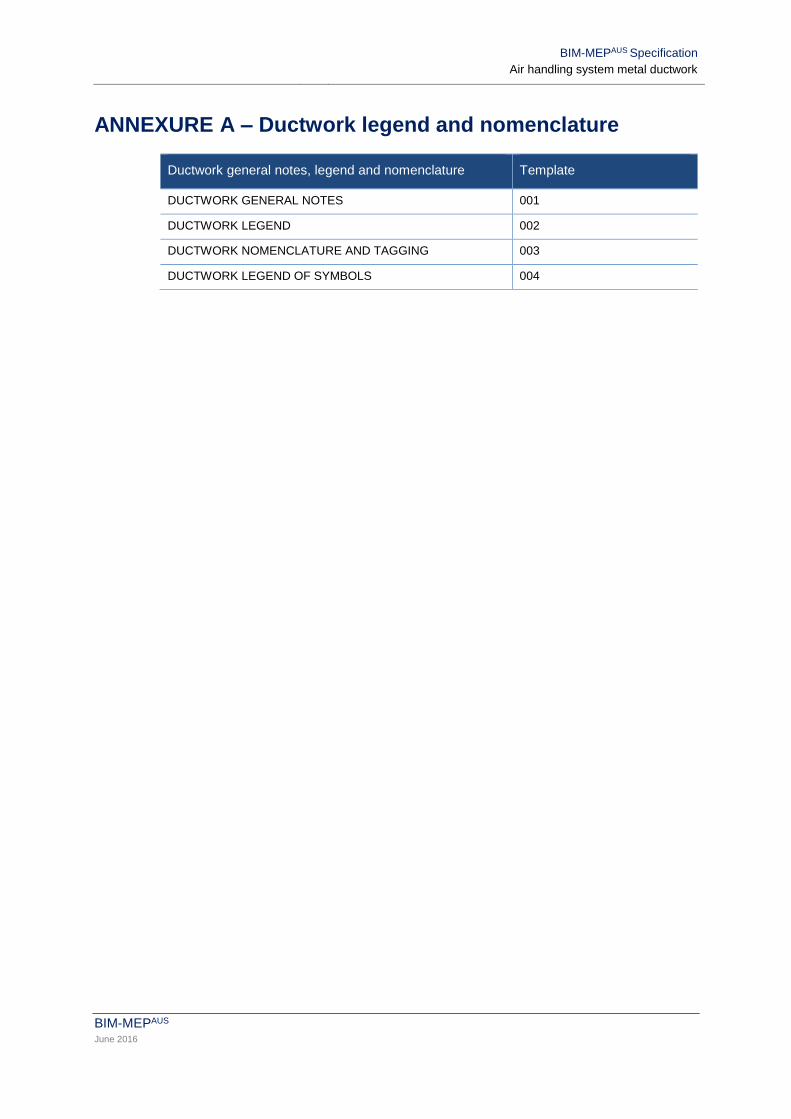
ANNEXURE A – Ductwork legend and nomenclature
Ductwork general notes, legend and nomenclature Template
DUCTWORK GENERAL NOTES 001
DUCTWORK LEGEND 002
DUCTWORK NOMENCLATURE AND TAGGING 003
DUCTWORK LEGEND OF SYMBOLS 004

BIM-MEPAUS Specification
Air handling system metal ductwork
BIM-MEPAUS June 2016
ANNEXURE B – Rectangular duct templates
Rectangular standard straights Template
GALVANISED STEEL 101
STAINLESS STEEL 102
ALUMINUM 103
Rectangular standard fittings Template
RADIUS BENDS 201
MITRED BENDS 202
OFFSETS 203
TRANSITIONS 204
RECTANGULAR TO ROUNDS 205
TEES 206
TROUSERS 207
SIDE BRANCHES 208
SHOES 209
RECTANGULAR SPIGOTS 210
DUCT ENDS 211
SUBDUCTS 212
Rectangular special fittings Template
NOT USED 300-399
Rectangular standard accessories Template
ACCESS PANELS 401
ACCESS DOORS 402
ROUND SPIGOTS FOR FLEXIBLE CONNECTIONS 403
OVAL SPIGOTS FOR FLEXIBLE CONNECTIONS 404
FLEXIBLE CONNECTORS 405
MESH SCREENS 406

BIM-MEPAUS Specification
Air handling system metal ductwork
BIM-MEPAUS June 2016
ANNEXURE C – Round duct templates
Standard straights Template
ROUND - METRIC 501
Round standard fittings Template
ROUND BENDS 510
ROUND 2 WAY 511
ROUND MITRED OFFSET 512
ROUND OFFSETS 513
ROUND REDUCERS 514
ROUND TAKE-OFFS 515
ROUND RECTANGULAR SPIGOTS 516
ROUND DUCT END - CONNECTORS 517
Round accessories Template
ROUND HANGERS 580
ROUND ACCESS PANELS 581

BIM-MEPAUS Specification
Air handling system metal ductwork
BIM-MEPAUS June 2016
ANNEXURE D – Oval duct templates
Standard straights Template
OVAL - METRIC 550
Oval standard fittings Template
OVAL BENDS 560
OVAL OFFSETS 561
OVAL REDUCERS 562
OVAL TAKE-OFFS 563
OVAL RECTANGULAR SPIGOT 564
OVAL DUCT ENDS 565

BIM-MEPAUS Specification
Air handling system metal ductwork
BIM-MEPAUS June 2016
ANNEXURE E –CID Standard Option Settings
The following section provides the standard CID Option Default Settings embedded in the Revit Fabrication Parts
for the standard straight and fittings provided in the BIM-MEPAUS Template.

BIM-MEPAUS Specification
Air handling system metal ductwork
BIM-MEPAUS June 2016
E.101 Standard Straight CID 866
E.201 Bends Radius CID 17

BIM-MEPAUS Specification
Air handling system metal ductwork
BIM-MEPAUS June 2016
E.202 Bends Mitred CID 20
E.203 Offsets Radius CID 9

BIM-MEPAUS Specification
Air handling system metal ductwork
BIM-MEPAUS June 2016
E.203 Offsets Mitred CID 30
E.204 Transitions CID2

BIM-MEPAUS Specification
Air handling system metal ductwork
BIM-MEPAUS June 2016
E.205 Rectangular to Rounds CID 8
E.206 Tees – Mitred CID 14

BIM-MEPAUS Specification
Air handling system metal ductwork
BIM-MEPAUS June 2016
E.206 Tees Radius CID 14
E.207 Trousers CID 328

BIM-MEPAUS Specification
Air handling system metal ductwork
BIM-MEPAUS June 2016
E.208 Side Branches CID 18
E.209 Shoes CID 17

BIM-MEPAUS Specification
Air handling system metal ductwork
BIM-MEPAUS June 2016
E.210 Rectangular Spigots CID 1
E.211 Duct Ends

BIM-MEPAUS Specification
Air handling system metal ductwork
BIM-MEPAUS June 2016
E.211 Duct Ends (TDF CAP)