Embed Size (px)
Citation preview
BIM-MEPAUS SPECIFICATION Transformers
Issued By: BIM-MEPAUS
30 Cromwell Street, Burwood 3205 VIC Australia
Revision: B
Date July 2017
BIM-MEPAUS Specification
Transformers
BIM-MEPAUS
July 2017
Acknowledgements
BIM-MEPAUS acknowledges the contributions of the following organisations involved in the development of this
specification including principal contributors:
• A.G. Coombs
• A2K Technologies
• GE Transformers
• Lucid Consulting
• Nilsen
• PowerCad
• Schneider-Electric
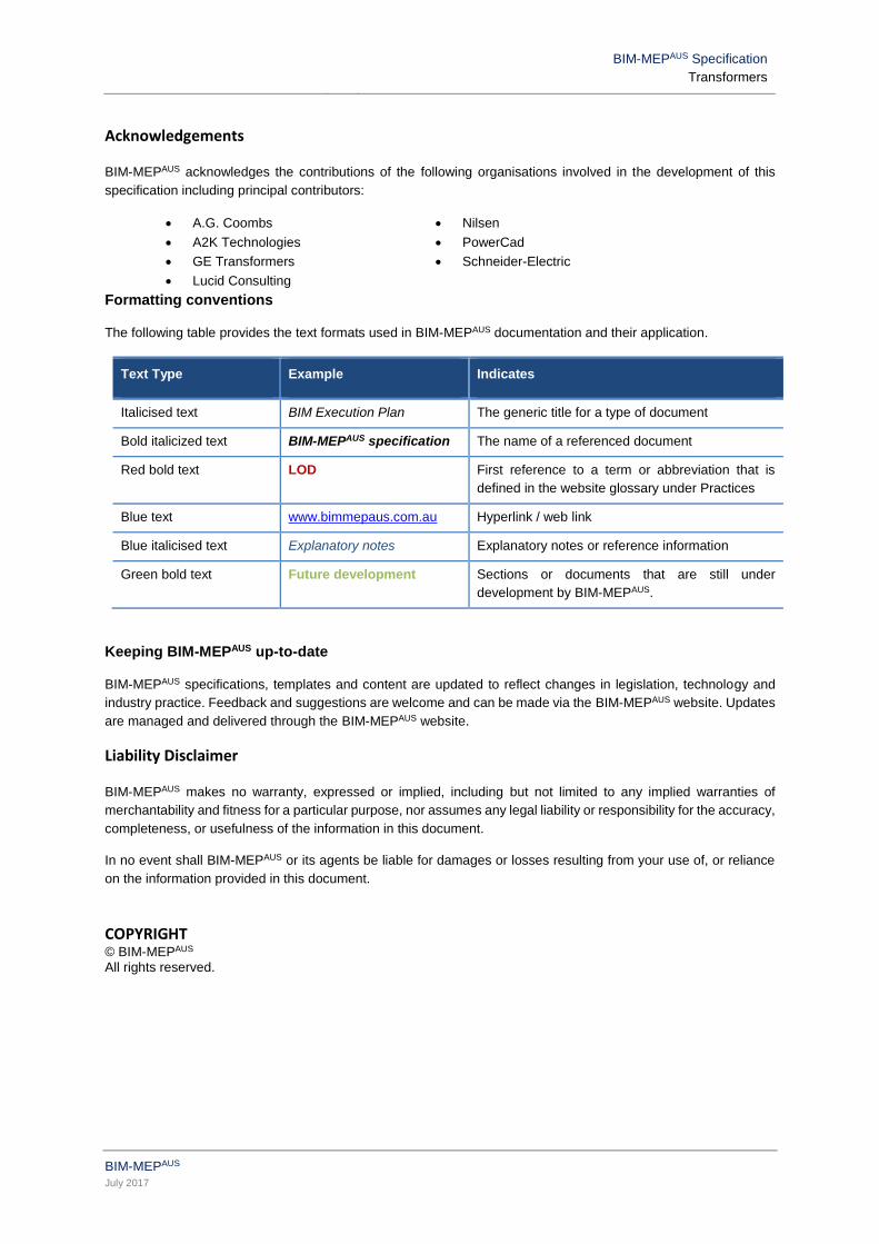
Formatting conventions
The following table provides the text formats used in BIM-MEPAUS documentation and their application.
Text Type Example Indicates
Italicised text BIM Execution Plan The generic title for a type of document
Bold italicized text BIM-MEPAUS specification The name of a referenced document
Red bold text LOD First reference to a term or abbreviation that is
defined in the website glossary under Practices
Blue text www.bimmepaus.com.au Hyperlink / web link
Blue italicised text Explanatory notes Explanatory notes or reference information
Green bold text Future development Sections or documents that are still under
development by BIM-MEPAUS.
Keeping BIM-MEPAUS up-to-date
BIM-MEPAUS specifications, templates and content are updated to reflect changes in legislation, technology and
industry practice. Feedback and suggestions are welcome and can be made via the BIM-MEPAUS website. Updates
are managed and delivered through the BIM-MEPAUS website.
Liability Disclaimer
BIM-MEPAUS makes no warranty, expressed or implied, including but not limited to any implied warranties of
merchantability and fitness for a particular purpose, nor assumes any legal liability or responsibility for the accuracy,
completeness, or usefulness of the information in this document.
In no event shall BIM-MEPAUS or its agents be liable for damages or losses resulting from your use of, or reliance
on the information provided in this document.
COPYRIGHT © BIM-MEPAUS All rights reserved.
BIM-MEPAUS Specification
Transformers
BIM-MEPAUS
July 2017
Table of Contents
1 INTRODUCTION .............................................................................................................. 4
1.1 Scope ........................................................................................................................................................ 4
1.2 BIM-MEPAUS reference documents ............................................................................................................ 4
1.3 Objectives .................................................................................................................................................. 4
1.4 BIM-MEPAUS Schema ................................................................................................................................ 4
2 APPLICABLE STANDARDS ............................................................................................ 5
3 MODELS .......................................................................................................................... 6
3.1 Model workflow .......................................................................................................................................... 6
3.2 Generic design content .............................................................................................................................. 6
3.3 Manufacturer certified content ................................................................................................................... 6
4 SHARED PARAMETER SCHEDULING ........................................................................... 7
5 TRANSFORMER SPECIFICATION .................................................................................. 8
5.1 Transformer type classification .................................................................................................................. 8
5.2 Transformer Selection ............................................................................................................................... 8
5.3 Transformer Sizing .................................................................................................................................... 8
5.4 Transformer Procurement ......................................................................................................................... 9
5.5 IP Ratings .................................................................................................................................................. 9
5.6 Design Life ................................................................................................................................................ 9
5.7 Access and clearance zones ..................................................................................................................... 9
6 REVIT FUNCTIONALITY ................................................................................................10
6.1 Category classification ............................................................................................................................. 10
6.2 Functional type and sub-type .................................................................................................................. 10
6.3 Family naming syntax .............................................................................................................................. 10
6.4 Family/type version control ...................................................................................................................... 10
6.5 Omniclass ................................................................................................................................................ 11
6.6 Connector settings ................................................................................................................................... 11
6.7 Family geometry ...................................................................................................................................... 12
6.8 Clearance and access zones .................................................................................................................. 12
7 PARAMETER SCHEDULES ...........................................................................................13
7.1 Identity schedule...................................................................................................................................... 13
7.2 BIM classification schedule ..................................................................................................................... 14
7.3 System analysis schedule ....................................................................................................................... 14
7.4 Green building properties schedule ......................................................................................................... 14
7.5 Performance/Quality schedule ................................................................................................................ 15
7.6 Manufacturer schedule ............................................................................................................................ 17
7.7 Commissioning schedule ......................................................................................................................... 17
7.8 Completion schedule ............................................................................................................................... 18
7.9 Generic design model schedule .............................................................................................................. 19
7.10 MCM schedule......................................................................................................................................... 21
BIM-MEPAUS Specification
Transformers
BIM-MEPAUS Page 4
July 2017
1 INTRODUCTION
1.1 Scope
This document sets out the BIM-MEPAUS specification for the following families:
• Transformer – Dry Type
• Transformer – Dry Type Enclosed
• Transformer – Oil Immersed Type
• Transformer – Dry Type Pad Mounted Kiosk
• Transformer – Oil Immersed Type Pad Mounted Kiosk
1.2 BIM-MEPAUS reference documents
This specification should be read in conjunction with the following specifications and documents:
• BIM-MEPAUS Electrical Power systems, plant and equipment schedule – this Excel based schedule
provides the complete listing of electrical systems, plant and equipment names as well as the system
colour schema.
• BIM-MEPAUS Low / Medium Voltage Transformer product data template – this Excel based schedule
details the BMA IFM and generic design families provided by BIM-MEPAUS including the catalogue of size
types provided for design purposes. The workbook also provides the complete schedule of shared
parameters and the product data templates for designers and product manufacturers.
• BIM-MEPAUS Master shared parameter schedule – this document provides the reference source for all
shared parameter names used within BIM-MEPAUS Generic Design and Manufacturer Certified Model
(MCM) content models together with the Revit MEP classification of each parameter and its associated
BIM-MEPAUS GUID.
• BIM-MEPAUS Plant, equipment and fitting scheduling specification – this document details the
technical and workflow requirements in relation to shared parameter scheduling.
These documents can be accessed through the BIM-MEPAUS website.
1.3 Objectives
Benefits sought through the development and implementation of this BIM-MEPAUS specification include:
• A structured approach to the specification and modelling of transformers;
• Reliable and accurate Design to Commissioned As-built workflows; and
• Industry standardization delivering improved supply chain efficiency and reduced project costs and risks
to the client and project team.
1.4 BIM-MEPAUS Schema
Within the BIM-MEPAUS, the plant, equipment and fitting schema is used to determine the component life cycle
scheduling requirements, transformers are classified as plant.
BIM-MEPAUS Specification
Transformers
BIM-MEPAUS Page 5
July 2017
2 APPLICABLE STANDARDS
There are a number of requirements in the National Construction Code as well as relevant Australian and
international standards that relate to electrical transformer design and selection.
Codes and standards referenced in this specification include:
General Requirements
NCC/ BCA : National Construction Code / Building Code of Australia
Electrical Installations
AS 3000 -2007 : Electrical Wiring Rules
Transformers
AS 2374.1. 2016 : Power transformers – Minimum Energy Performance Standards (MEPS)
requirements for distribution transformers.
AS 3820 - 2009 : Essential safety requirements for electrical equipment
AS/NZS 60076.1 -2014 : Power transformers – General
AS 60076.2 – 2013 : Power transformers – Temperature rise for liquid immersed transformers
AS 60076.3 – 2013 : Power transformers – Insulation levels, dielectric test and external clearances
in air
AS 60076.10 – 2009 : Power transformers – Determination of sound levels
AS 60076.11 - 2016 : Power transformers – Dry type transformers
AS 60529 - 2004 : Degrees of protection provided by enclosures (IP Code)
IEC 60076.12 – 2008 : Power transformers – loading guide for dry type power transformers
BIM-MEPAUS Specification
Transformers
BIM-MEPAUS Page 6
July 2017
3 MODELS
3.1 Model workflow
One of the principle aims of BIM-MEPAUS is to enable efficient BIM workflows that see the design model
progressively refined through the design, virtual build and construction process to ultimately deliver a completed
Commissioned As-Built Model.
A key step in this process is the virtual build during which the change-out of the generic design components with
Manufacturer’s Certified Models (MCMs) occurs. These MCMs are able to support a range of construction and
commissioning workflows as well as the asset’s life cycle management post-handover.
The completed construction model generated through the virtual build is then used to drive a range of activities
including site layout, procurement and installation scheduling and tracking.
Once the installation is completed and the systems commissioned, as-built data and project completion information
are used to finalise the Commissioned-As Built Model for handover to the client.
3.2 Generic design content
BIM-MEPAUS generic design families provide a catalogue of sizes (types) that allow designers to spatially model to
LOD 300 as well as specify the transformer’s performance and quality requirements.
The generic design model shared parameters have been developed through industry consultation and are
considered those necessary to schedule the quality and performance requirements for tendering and procurement
purposes.
Design firms with content libraries can pre-populate these transformer design families with their specific quality
specifications in order to minimise repetitive data entry on each use in a project. This approach limits subsequent
scheduling to only those instance based performance parameters that are typically scheduled in specification
equipment schedules.
3.3 Manufacturer certified content
Manufacturer’s models are preferably generated from the BIM-MEPAUS Industry Foundation Models (IFM) and
are a single type family that has the transformer geometry needed for the virtual build plus the manufacturer data
for the specific transformer to be supplied to the project.
BIM-MEPAUS certified manufacturer models are fully interchangeable with the generic design models and provide:
• Accurate geometry
• Performance data
• Full BIM-MEPAUS Revit operability.
Where the data is not able to be provided by the manufacturer in Revit shared parameter format, manufacturer data
should be delivered in Excel format using the BIM-MEPAUS Product Data Templates to allow the data to be efficiently
imported by the specialist trade contractor into their scheduling database or Revit virtual build model.
Microsoft Excel based product data templates are provided for this purpose on the BIM-MEPAUS website under the
specification product templates section. Where required additional fields can be drawn from the shared parameter
schedules in this specification to provide more extensive product data as required.
As the MCM and supporting shared parameter schedule replaces the certified drawings and technical schedules
that have traditionally been provided by manufacturers, the model accuracy should be no less than that provided
by a manufacturer’s certified drawing.
Manufacturer’s certified models should preferably include a link to a pdf or web page providing pre-commissioning
checklists for modellers and shop drawers to facilitate the proper incorporation of the component into the model as
well as providing the pre-commissioning check sheet for the project site team.
BIM-MEPAUS Specification
Transformers
BIM-MEPAUS Page 7
July 2017
4 SHARED PARAMETER SCHEDULING
The shared parameter schema has been developed to effectively support data requirements for design,
procurement and commissioning as well as life cycle asset management. All BIM-MEPAUS plant and equipment
models have the same schedule structure shown below.
• Identity
• BIM Classification
• System Analysis
• Green Building Properties
• Performance / Quality
• Manufacturer
• Commissioning
• Completion
System Analysis, Green Building Properties and Commissioning schedules are only included where applicable or
where they have been defined by a relevant standard.
The schedules are progressively completed as the MEP services model progresses through design and virtual
construction to a fully completed Commissioned As-built component within the final model.
Schedule Section Generic Design / MCM
Model schedule
Schedule completion by
Identity Generic design model Designer / Manufacturer / Installer
BIM Classification Generic design model Designer
System Analysis Generic design model Designer
Green Building Properties Generic design model / MCM model Designer / Installer / Manufacturer
Performance /Quality Generic design model / MCM model Designer / Installer
Manufacturer MCM model Manufacturer
Commissioning MCM model Installer
Completion Schedule MCM model Installer
The identity schedule must be completed for all components and once the values are defined are fixed for the life
of the component.
It is not expected that all data will be carried in the Revit model with non-core data likely to be managed off model
using scheduling databases and/or spreadsheets. This non-core data is commonly required for the finalization of
procurement, commissioning and facility management purposes.
Manufacturer BIM data must be supplied in a format that can be imported into a data management system and/or
Revit based Virtual Construction model with suitable formats including:
• MCM model incorporating BIM-MEPAUS Product Data Template shared parameters
• MCM geometry model with supporting BIM-MEPAUS Product Data Template Excel file.
To allow efficient and reliable data exchanges, it is critical that the BIM-MEPAUS shared parameter names and
respective GUIDs be used.
Parameters indicated in bold font are core Revit model data expected to reside in the model whilst those in italics
are non-core data that can be managed either in the Revit MEP model or off model in a scheduling database.
Parameters notated with the symbol have an industry defined set of allowable values or descriptions that are
listed in the master BIM-MEPAUS shared parameter schedule.
It is noted that BIM-MEPAUS compliant manufacturer’s certified models can be used for the basis of design where deemed appropriate by the designer and/or where specific manufacturer plant and equipment is to be nominated.
BIM-MEPAUS Specification
Transformers
BIM-MEPAUS Page 8
July 2017
5 TRANSFORMER SPECIFICATION
The following guidance has been developed through the industry consultation process as particular areas requiring
focus during the completion of the transformer quality/performance schedules.
5.1 Transformer type classification
The transformer classification schedule is based on the insulation medium and the form of heat rejection.
ANAN – Air Natural Air Natural (air insulated / natural ventilation cooled)
ANAF – Air Natural Air Forced (air insulated / forced draft air cooled)
ONAN – Oil Natural Air Natural (Oil immersed / natural ventilation cooled)
ONAF – Oil Natural Air Forced (Oil immersed / forced draft cooled)
KNAN – Synthetic Oil Air Natural (Synthetic oil immersed / natural ventilation cooled)
KNAF- Synthetic Oil Air Natural (Synthetic oil immersed / forced draft cooled)
5.2 Transformer Selection
For the built environment applications, dry type enclosed naturally ventilated transformers are typically specified to
be provided with HV and LV coils of copper and cast resin construction. Aluminum coils may be used as an
alternative to copper and for LV coils impregnated insulation may be utilized as an alternative to cast resin.
Oil immersed transformers require provision of bunding and blast walls and hence are typically avoided where a
transformer is located within a building.
The majority of transformers supplied in Australia for the built environment have the following core specification
parameters:
Vector Connections : Dyn11
Ambient Class : C2
Environmental Class : E2
Fire Behaviour Class : F1
The temperature rise determines the insulation class with 150oC indicating Class F and 180oC indicating Class H.
Noise criteria are typically based on the kVA rating with the Australian standards providing both standard and
reduced noise level ratings.
5.3 Transformer Sizing
The standard transformer sizes are:
100kVA 750kVA 1600kVA 4000kVA
200kVA 1000kVA 2000kVA 5000kVA
315kVA 1250kVA 2500kVA
500kVA 1500kVA 3000kVA
The majority of transformers for commercial applications would be selected in the 500kVA to 2000kVA range, the
sizes indicated in bold are the sizes provided in the generic family catalogue.
BIM-MEPAUS Specification
Transformers
BIM-MEPAUS Page 9
July 2017
5.4 Transformer Procurement
The procurement of the transformers varies depending on the location and project type with transformers supplied
by the either the energy utility or by the proprietor. In both cases the transformer technical schedule will be required
to complete the power system design.
5.5 IP Ratings
IP ratings for commercial applications located indoors are typically IP 21, whilst for industrial applications IP 41 is
commonly specified to mitigate risks related to dust and moisture.
5.6 Design Life
Nominal design life of transformers is typically between 20-25 years; however it is not uncommon for transformers
to achieve service lives in excess of 40 years. The service life in practice is determined by a range of factors
including loading and number of power surges experienced by the transformer over its life.
5.7 Access and clearance zones
The access requirements and clearance zones will be determined by the supply authority and relevant Australia
Standards.
In transformer rooms with limited space it may be necessary to specify the enclosure doors to be lift off type rather
than hinged.
As transformers are typically heavy it is important to assure that the transformer replacement route has adequate
physical and structural strength to allow the transformer to be moved.
BIM-MEPAUS Specification
Transformers
BIM-MEPAUS Page 10
July 2017
6 REVIT FUNCTIONALITY
6.1 Category classification
All transformer families are designated in Revit MEP as electrical equipment.
6.2 Functional type and sub-type
The design and manufacturer models functional type and sub-type are:
• Functional Type : Transformer
• Sub Type : Dry Type Top Connected
: Dry Type Bottom Connected
: Dry Type Enclosed Top Connected
: Dry Type Enclosed Bottom Connected
: Oil Immersed Type Top Connected
: Oil Immersed Type Bottom Connected
: Dry Type Pad Mounted Kiosk
: Oil Immersed Type Pad Mount Kiosk
6.3 Family naming syntax
The transformer family naming convention is as follows
Format:
Generic Design : <Functional Type>_< Sub-Functional Type>_<Generic>_<BMA>
MCM : <Functional Type>_< Sub-Functional Type>_<ManufacturerName>_<Type Descriptor>
Example family names:
Generic Design Model
TX_DryTypeTopConnected_Generic_IFM
Manufacturer Certified Model
TX_DryTypeTopConnected_Model Name 2000kVA
6.4 Family/type version control
Family Identification parameters are used for source and version control and are embedded in the Family
Parameters. They do not appear in the BIM-MEPAUS shared parameter schedules as they are not intended to be
modified by designers or constructors.
Design Family – Single Type
Family Identification Unit /Type Sample Value
FamilyName Text TX_DryType_Generic_BMA
Version Text 2017
CreatedOn Text 201705
CreatedBy Text BMA
BIM-MEPAUS Specification
Transformers
BIM-MEPAUS Page 11
July 2017
Manufacturer’s Certified Model – single type
Family Identification Unit /Type Sample Value
FamilyName Text DB_DryTypeIEnclosed_ Manufacturer Name_ Model Number
TypeName Text Size
Version Text 2017-05
CreatedOn Text 20170531
CreatedBy Text Modelling Company Name
6.5 Omniclass
The BIM Classification Code is a Revit System Parameter with the Transformer Classification.
System Parameter Unit /Type Value
OmniClassNumber Text 23-35 13 11
6.6 Connector settings
The following Revit connectors are applied to Transformer models:
ID Connector System Classification Placement Shape Calculation Method
1 Power – Unbalanced ELEC Face Power N/A
Parameter Value
System Type Power - Unbalanced
Number of Poles Mapped to SupplyPhase
Power Factor State Lagging
Load Classification Other
Load Sub-Classification Motor unchecked
Voltage Mapped to SupplyVoltage
Apparent Load Phase 1 0
Apparent Load Phase 2 0
Apparent Load Phase 3 0
Power Factor State 1
Utility unchecked
Connector Description
Note: To successfully connect a transformer up to an electrical system the “Distribution System” and “Secondary
Distribution System” parameters need to be allocated. Distribution systems can only be added after they are defined
in the Revit projects electrical settings once the Revit transformer family is loaded into a Revit project model.
BIM-MEPAUS Specification
Transformers
BIM-MEPAUS Page 12
July 2017
6.7 Family geometry
Family geometry is controlled by instance based parameters with the intention that the modeller should not need to
modify the geometry of generic design models or Manufacturer’s Certified Models.
It is noted that the Family Dimension Parameters are used to schedule those parameters that define the type (size
or capacity), with all detailed geometry dimensions listed separately under the Geometry Grouping.
Critical dimensions in relation to the model geometry are:
• Transformer height, width and depth
• Panel opening size and type (Door size and locations)
• Maintenance Clearance.
• Fixing method
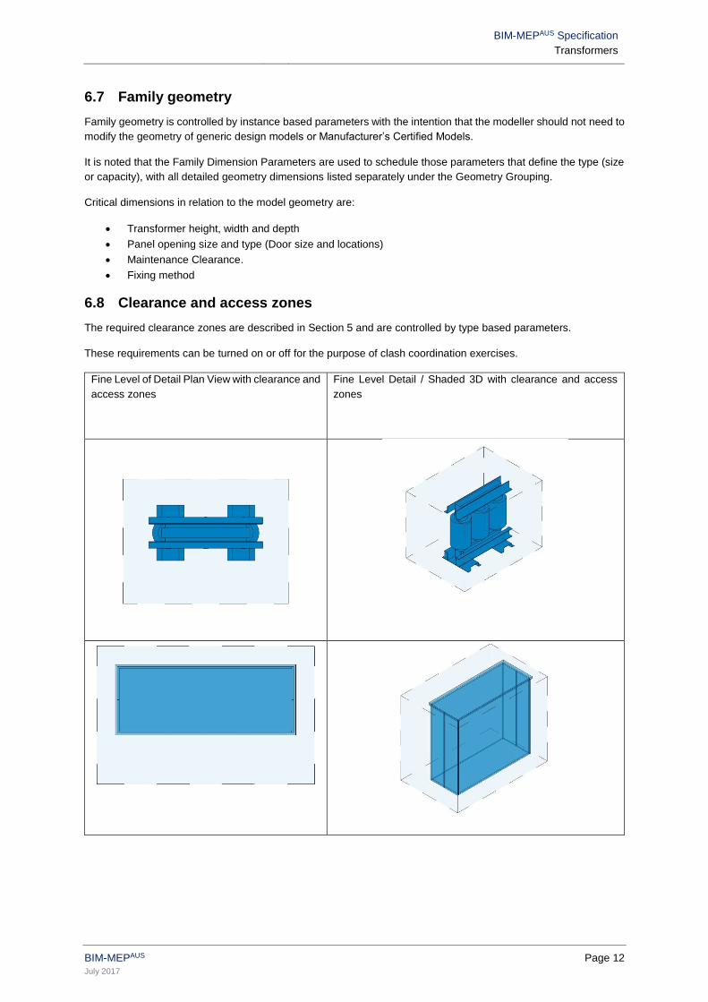
6.8 Clearance and access zones
The required clearance zones are described in Section 5 and are controlled by type based parameters.
These requirements can be turned on or off for the purpose of clash coordination exercises.
Fine Level of Detail Plan View with clearance and
access zones
Fine Level Detail / Shaded 3D with clearance and access
zones
BIM-MEPAUS Specification
Transformers
BIM-MEPAUS Page 13
July 2017
7 PARAMETER SCHEDULES
The schedule structure and parameters have been developed to meet the needs of the BIM-MEPAUS integrated
project delivery workflows as well as support future asset life cycle management requirements. The Product Data
Templates form a subset of the overall shared parameter scheme.
Refer to Section 4 - Shared Parameter Scheduling for a detailed overview of the intended use and application of
the schedules.
Parameter fields indicated in black bold text are included in the Product Data Template with the Design Model
Schedule being provided with a sub-set of these parameters detailed in Section 7.9 Generic Design Model
Schedule.
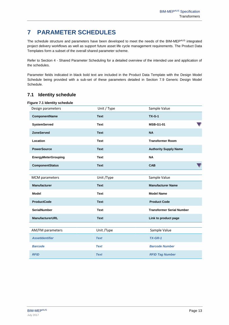
7.1 Identity schedule
Figure 7.1 Identity schedule
Design parameters Unit / Type Sample Value
ComponentName Text TX-G-1
SystemServed Text MSB-G1-01
ZoneServed Text NA
Location Text Transformer Room
PowerSource Text Authority Supply Name
EnergyMeterGrouping Text NA
ComponentStatus Text CAB
MCM parameters Unit /Type Sample Value
Manufacturer Text Manufacturer Name
Model Text Model Name
ProductCode Text Product Code
SerialNumber Text Transformer Serial Number
ManufacturerURL Text Link to product page
AM/FM parameters Unit /Type Sample Value
AssetIdentifier Text TX-GR-1
Barcode Text Barcode Number
RFID Text RFID Tag Number
BIM-MEPAUS Specification
Transformers
BIM-MEPAUS Page 14
July 2017
7.2 BIM classification schedule
The BIM classification codes are based on the OmniClass Construction Classification System (known as
OmniClass™ or OCCS) for the construction industry and Natspec.
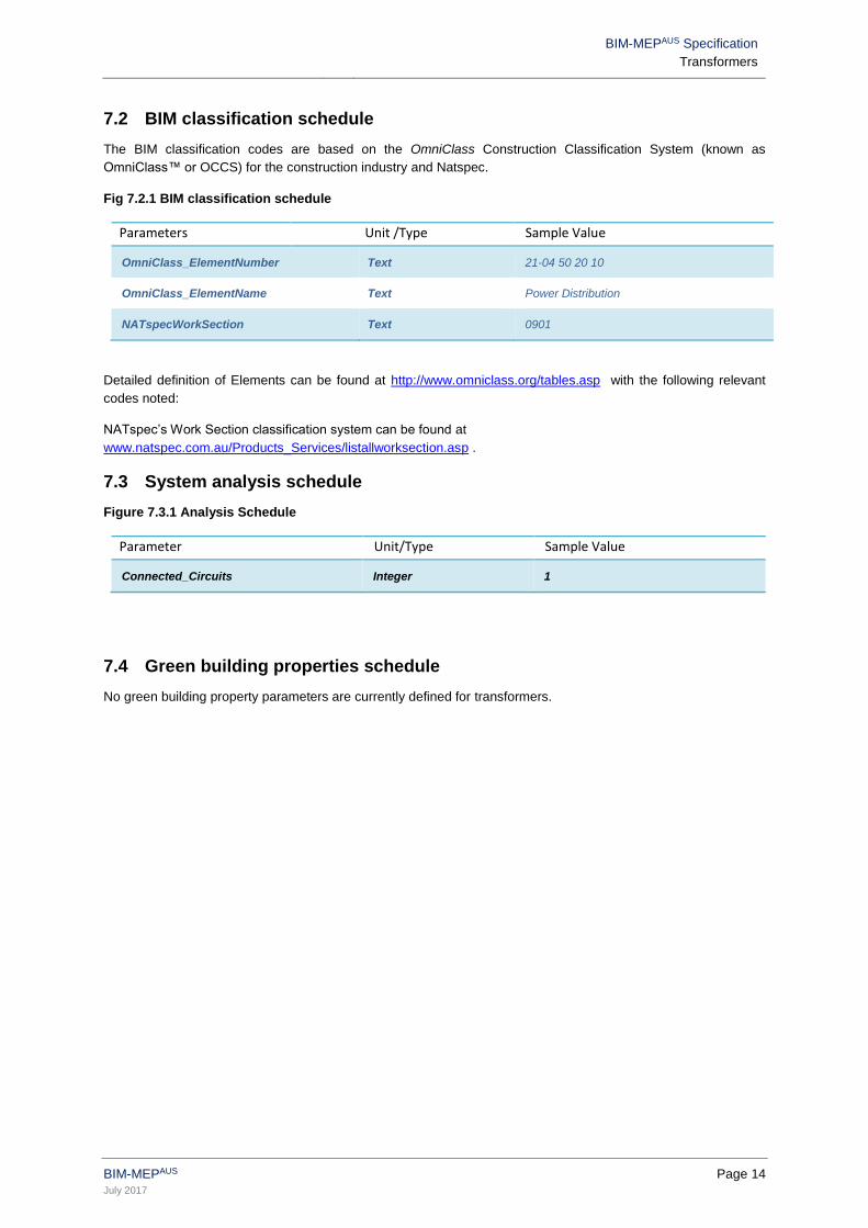
Fig 7.2.1 BIM classification schedule
Parameters Unit /Type Sample Value
OmniClass_ElementNumber Text 21-04 50 20 10
OmniClass_ElementName Text Power Distribution
NATspecWorkSection Text 0901
Detailed definition of Elements can be found at http://www.omniclass.org/tables.asp with the following relevant
codes noted:
NATspec’s Work Section classification system can be found at
www.natspec.com.au/Products_Services/listallworksection.asp .
7.3 System analysis schedule
Figure 7.3.1 Analysis Schedule
Parameter Unit/Type Sample Value
Connected_Circuits Integer 1
7.4 Green building properties schedule
No green building property parameters are currently defined for transformers.
BIM-MEPAUS Specification
Transformers
BIM-MEPAUS Page 15
July 2017
7.5 Performance/Quality schedule
The performance and quality schedule details the performance and quality requirements for the transformers.
The schedule brings together a number of typical specification requirements including those related to transformer
design and performance, mechanical-electrical system integration and vibration and noise isolation.
The Manufacturer’s certified model may overwrite some sections of this schedule replacing the design performance
requirements with submitted performance data.
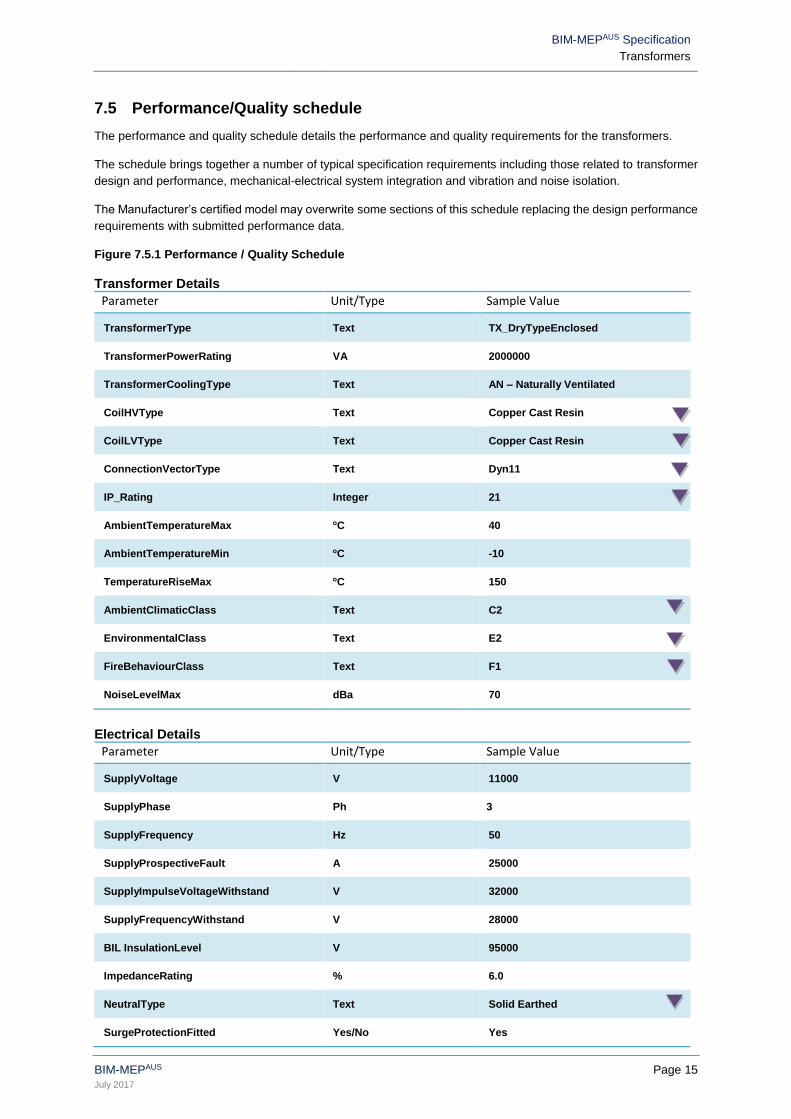
Figure 7.5.1 Performance / Quality Schedule
Transformer Details
Parameter Unit/Type Sample Value
TransformerType Text TX_DryTypeEnclosed
TransformerPowerRating VA 2000000
TransformerCoolingType Text AN – Naturally Ventilated
CoilHVType Text Copper Cast Resin
CoilLVType Text Copper Cast Resin
ConnectionVectorType Text Dyn11
IP_Rating Integer 21
AmbientTemperatureMax oC 40
AmbientTemperatureMin oC -10
TemperatureRiseMax oC 150
AmbientClimaticClass Text C2
EnvironmentalClass Text E2
FireBehaviourClass Text F1
NoiseLevelMax dBa 70
Electrical Details
Parameter Unit/Type Sample Value
SupplyVoltage V 11000
SupplyPhase Ph 3
SupplyFrequency Hz 50
SupplyProspectiveFault A 25000
SupplyImpulseVoltageWithstand V 32000
SupplyFrequencyWithstand V 28000
BIL InsulationLevel V 95000
ImpedanceRating % 6.0
NeutralType Text Solid Earthed
SurgeProtectionFitted Yes/No Yes
BIM-MEPAUS Specification
Transformers
BIM-MEPAUS Page 16
July 2017
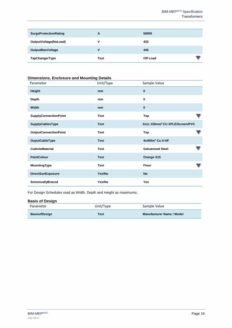
SurgeProtectionRating A 50000
OutputVoltage(NoLoad) V 433
OutputMaxVoltage V 440
TapChangerType Text Off Load
Dimensions, Enclosure and Mounting Details
Parameter Unit/Type Sample Value
Height mm 0
Depth mm 0
Width mm 0
SupplyConnectionPoint Text Top
SupplyCablesType Text 3x1c 150mm2 CU XPLE/Screen/PVC
OutputConnectionPoint Text Top
OuputCableType Text 4x400m2 Cu X-HF
CubicleMaterial Text Galvanised Steel
PaintColour Text Orange X15
MountingType Text Floor
DirectSunExposure Yes/No No
SeismicallyBraced Yes/No Yes
For Design Schedules read as Width, Depth and Height as maximums.
Basis of Design
Parameter Unit/Type Sample Value
BasisofDesign Text Manufacturer Name / Model
BIM-MEPAUS Specification
Transformers
BIM-MEPAUS Page 17
July 2017
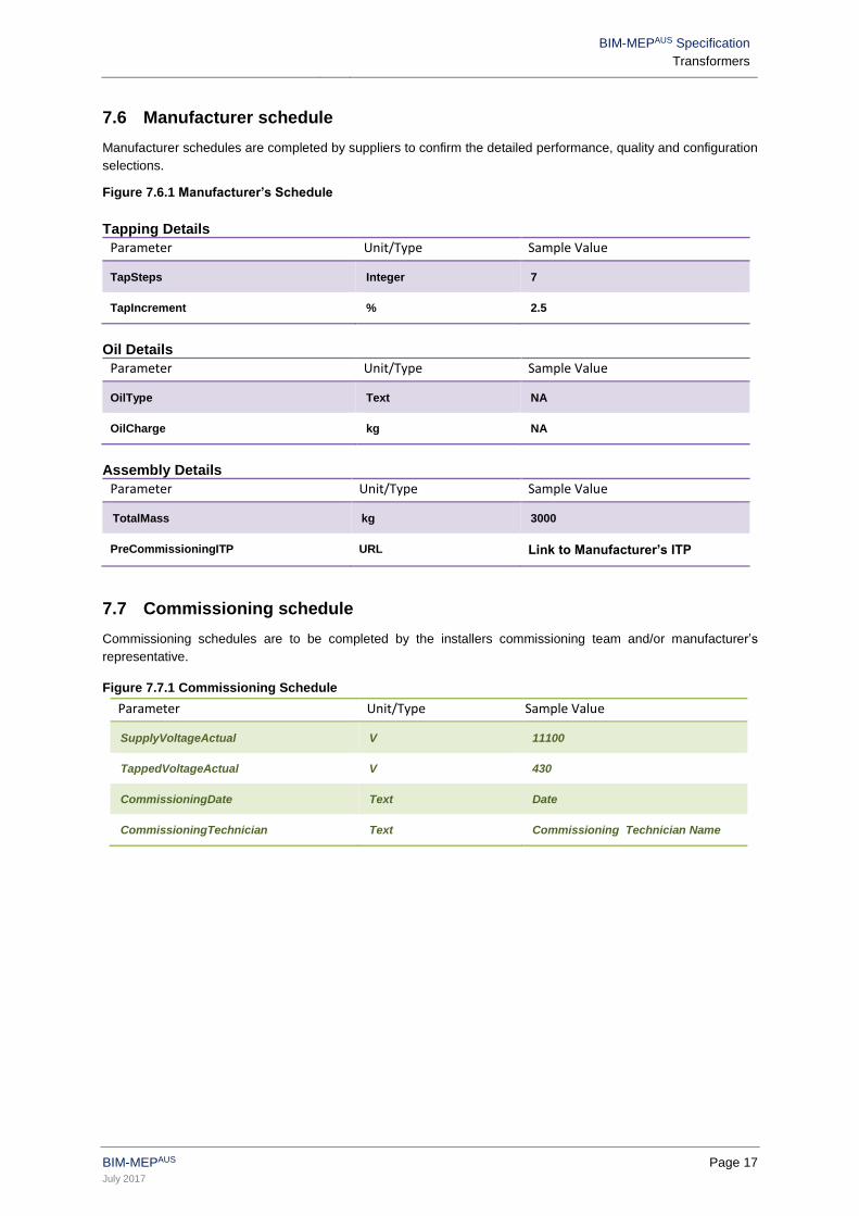
7.6 Manufacturer schedule
Manufacturer schedules are completed by suppliers to confirm the detailed performance, quality and configuration
selections.
Figure 7.6.1 Manufacturer’s Schedule
Tapping Details
Parameter Unit/Type Sample Value
TapSteps Integer 7
TapIncrement % 2.5
Oil Details
Parameter Unit/Type Sample Value
OilType Text NA
OilCharge kg NA
Assembly Details
Parameter Unit/Type Sample Value
TotalMass kg 3000
PreCommissioningITP URL Link to Manufacturer’s ITP
7.7 Commissioning schedule
Commissioning schedules are to be completed by the installers commissioning team and/or manufacturer’s
representative.
Figure 7.7.1 Commissioning Schedule
Parameter Unit/Type Sample Value
SupplyVoltageActual V 11100
TappedVoltageActual V 430
CommissioningDate Text Date
CommissioningTechnician Text Commissioning Technician Name
BIM-MEPAUS Specification
Transformers
BIM-MEPAUS Page 18
July 2017
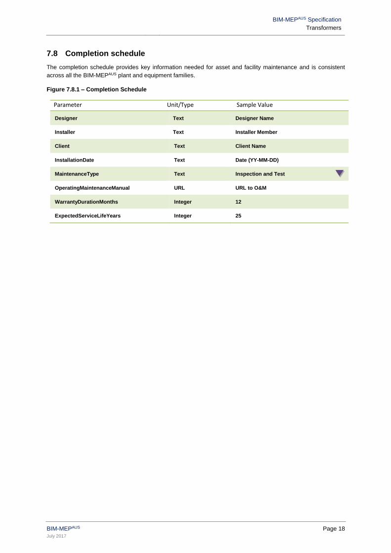
7.8 Completion schedule
The completion schedule provides key information needed for asset and facility maintenance and is consistent
across all the BIM-MEPAUS plant and equipment families.
Figure 7.8.1 – Completion Schedule
Parameter Unit/Type Sample Value
Designer Text Designer Name
Installer Text Installer Member
Client Text Client Name
InstallationDate Text Date (YY-MM-DD)
MaintenanceType Text Inspection and Test
OperatingMaintenanceManual URL URL to O&M
WarrantyDurationMonths Integer 12
ExpectedServiceLifeYears Integer 25
BIM-MEPAUS Specification
Transformers
BIM-MEPAUS Page 19
July 2017
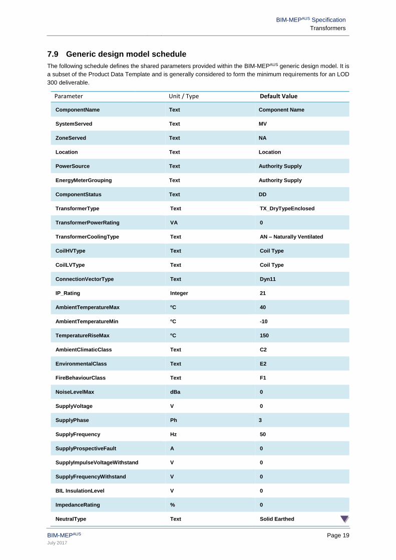
7.9 Generic design model schedule
The following schedule defines the shared parameters provided within the BIM-MEPAUS generic design model. It is
a subset of the Product Data Template and is generally considered to form the minimum requirements for an LOD
300 deliverable.
Parameter Unit / Type Default Value
ComponentName Text Component Name
SystemServed Text MV
ZoneServed Text NA
Location Text Location
PowerSource Text Authority Supply
EnergyMeterGrouping Text Authority Supply
ComponentStatus Text DD
TransformerType Text TX_DryTypeEnclosed
TransformerPowerRating VA 0
TransformerCoolingType Text AN – Naturally Ventilated
CoilHVType Text Coil Type
CoilLVType Text Coil Type
ConnectionVectorType Text Dyn11
IP_Rating Integer 21
AmbientTemperatureMax oC 40
AmbientTemperatureMin oC -10
TemperatureRiseMax oC 150
AmbientClimaticClass Text C2
EnvironmentalClass Text E2
FireBehaviourClass Text F1
NoiseLevelMax dBa 0
SupplyVoltage V 0
SupplyPhase Ph 3
SupplyFrequency Hz 50
SupplyProspectiveFault A 0
SupplyImpulseVoltageWithstand V 0
SupplyFrequencyWithstand V 0
BIL InsulationLevel V 0
ImpedanceRating % 0
NeutralType Text Solid Earthed
BIM-MEPAUS Specification
Transformers
BIM-MEPAUS Page 20
July 2017
SurgeProtectionFitted Yes/No Yes
SurgeProtectionRating A 0
OutputVoltage(NoLoad) V 433
OutputMaxVoltage V 440
TapChangerType Text Off Load
Height mm 2000
Depth mm 1000
Width mm 2000
SupplyConnectionPoint Text Top
SupplyCablesType Text Cable Selection
OutputConnectionPoint Text Top
OuputCableType Text Cable Selection
CubicleMaterial Text Galvanised Steel
PaintColour Text Paint Colour
MountingType Text Floor
DirectSunExposure Yes/No No
SeismicallyBraced Yes/No Yes
BasisofDesign Text Manufacturer Name/ Model
BIM-MEPAUS Specification
Transformers
BIM-MEPAUS Page 21
July 2017
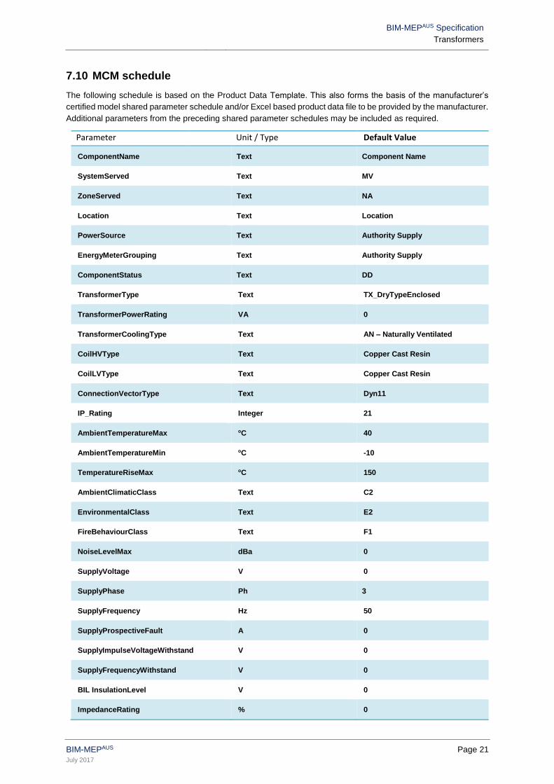
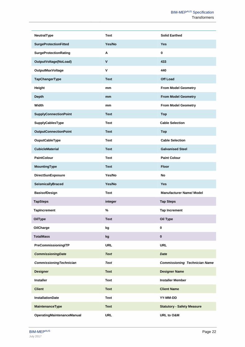
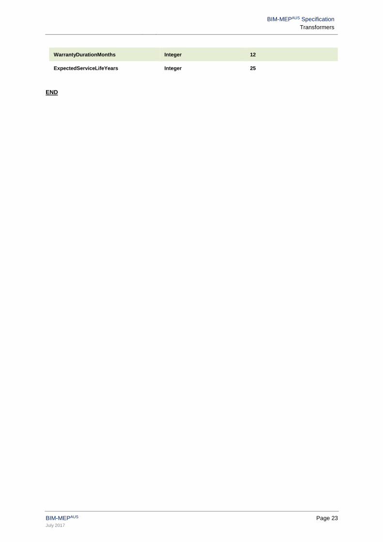
7.10 MCM schedule
The following schedule is based on the Product Data Template. This also forms the basis of the manufacturer’s
certified model shared parameter schedule and/or Excel based product data file to be provided by the manufacturer.
Additional parameters from the preceding shared parameter schedules may be included as required.
Parameter Unit / Type Default Value
ComponentName Text Component Name
SystemServed Text MV
ZoneServed Text NA
Location Text Location
PowerSource Text Authority Supply
EnergyMeterGrouping Text Authority Supply
ComponentStatus Text DD
TransformerType Text TX_DryTypeEnclosed
TransformerPowerRating VA 0
TransformerCoolingType Text AN – Naturally Ventilated
CoilHVType Text Copper Cast Resin
CoilLVType Text Copper Cast Resin
ConnectionVectorType Text Dyn11
IP_Rating Integer 21
AmbientTemperatureMax oC 40
AmbientTemperatureMin oC -10
TemperatureRiseMax oC 150
AmbientClimaticClass Text C2
EnvironmentalClass Text E2
FireBehaviourClass Text F1
NoiseLevelMax dBa 0
SupplyVoltage V 0
SupplyPhase Ph 3
SupplyFrequency Hz 50
SupplyProspectiveFault A 0
SupplyImpulseVoltageWithstand V 0
SupplyFrequencyWithstand V 0
BIL InsulationLevel V 0
ImpedanceRating % 0
BIM-MEPAUS Specification
Transformers
BIM-MEPAUS Page 22
July 2017
NeutralType Text Solid Earthed
SurgeProtectionFitted Yes/No Yes
SurgeProtectionRating A 0
OutputVoltage(NoLoad) V 433
OutputMaxVoltage V 440
TapChangerType Text Off Load
Height mm From Model Geometry
Depth mm From Model Geometry
Width mm From Model Geometry
SupplyConnectionPoint Text Top
SupplyCablesType Text Cable Selection
OutputConnectionPoint Text Top
OuputCableType Text Cable Selection
CubicleMaterial Text Galvanised Steel
PaintColour Text Paint Colour
MountingType Text Floor
DirectSunExposure Yes/No No
SeismicallyBraced Yes/No Yes
BasisofDesign Text Manufacturer Name/ Model
TapSteps integer Tap Steps
TapIncrement % Tap Increment
OilType Text Oil Type
OilCharge kg 0
TotalMass kg 0
PreCommissioningITP URL URL
CommissioningDate Text Date
CommissioningTechnician Text Commissioning Technician Name
Designer Text Designer Name
Installer Text Installer Member
Client Text Client Name
InstallationDate Text YY-MM-DD
MaintenanceType Text Statutory - Safety Measure
OperatingMaintenanceManual URL URL to O&M
BIM-MEPAUS Specification
Transformers
BIM-MEPAUS Page 23
July 2017
WarrantyDurationMonths Integer 12
ExpectedServiceLifeYears Integer 25
END