Embed Size (px)
Citation preview
BIM-MEPAUS SPECIFICATION Low/Medium voltage switchboards and electrical enclosures
Issued By: BIM-MEPAUS
30 Cromwell Street, Burwood 3205 VIC Australia
Revision: REV D
Date July 2017
BIM-MEPAUS Specification
Low/Medium voltage switchboards and electrical enclosures
BIM-MEPAUS
July 2017
Acknowledgements
BIM-MEPAUS acknowledges the contributions of the following organisations involved in the development of this
specification including principal contributors:
• Lucid Consulting
• Neilson
• PowerCad
• A.G. Coombs
• A2K Technologies
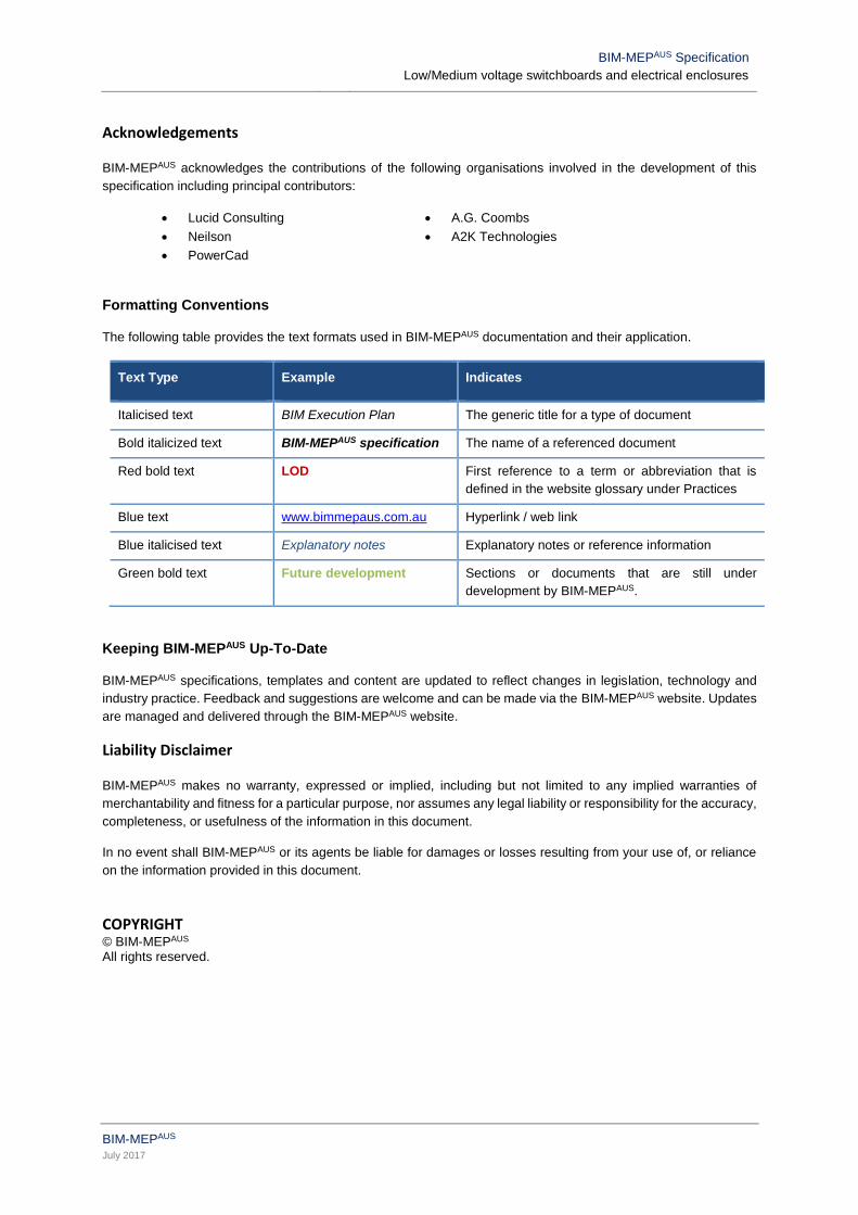
Formatting Conventions
The following table provides the text formats used in BIM-MEPAUS documentation and their application.
Text Type Example Indicates
Italicised text BIM Execution Plan The generic title for a type of document
Bold italicized text BIM-MEPAUS specification The name of a referenced document
Red bold text LOD First reference to a term or abbreviation that is
defined in the website glossary under Practices
Blue text www.bimmepaus.com.au Hyperlink / web link
Blue italicised text Explanatory notes Explanatory notes or reference information
Green bold text Future development Sections or documents that are still under
development by BIM-MEPAUS.
Keeping BIM-MEPAUS Up-To-Date
BIM-MEPAUS specifications, templates and content are updated to reflect changes in legislation, technology and
industry practice. Feedback and suggestions are welcome and can be made via the BIM-MEPAUS website. Updates
are managed and delivered through the BIM-MEPAUS website.
Liability Disclaimer
BIM-MEPAUS makes no warranty, expressed or implied, including but not limited to any implied warranties of
merchantability and fitness for a particular purpose, nor assumes any legal liability or responsibility for the accuracy,
completeness, or usefulness of the information in this document.
In no event shall BIM-MEPAUS or its agents be liable for damages or losses resulting from your use of, or reliance
on the information provided in this document.
COPYRIGHT © BIM-MEPAUS All rights reserved.
BIM-MEPAUS Specification
Low/Medium voltage switchboards and electrical enclosures
BIM-MEPAUS
July 2017
Table of Contents
1 INTRODUCTION .............................................................................................................. 1
1.1 Scope ........................................................................................................................................................ 1
1.2 BIM-MEPAUS Reference Documents .......................................................................................................... 1
1.3 Objectives .................................................................................................................................................. 1
1.4 BIM-MEPAUS Schema ................................................................................................................................ 1
2 APPLICABLE STANDARDS ............................................................................................ 2
3 MODELS .......................................................................................................................... 3
3.1 Model Workflow ......................................................................................................................................... 3
3.2 Generic Design Content ............................................................................................................................ 3
3.3 Manufacturer Certified Content ................................................................................................................. 3
3.4 Commissioned As-Built Model ................................................................................................................... 4
4 SHARED PARAMETER SCHEDULING ........................................................................... 5
5 SWITCHBOARD SPECIFICATION .................................................................................. 6
5.1 Types of Switchboards and Enclosures ..................................................................................................... 6
5.2 Switchboard Classifications ....................................................................................................................... 6
5.3 Access Clearance Zones ........................................................................................................................... 6
5.4 Smoke Seals ............................................................................................................................................. 7
5.5 Switchboard Sizing .................................................................................................................................... 7
5.6 Switchboard Panel Scheduling .................................................................................................................. 7
6 REVIT FUNCTIONALITY ................................................................................................. 8
6.1 Category Classification .............................................................................................................................. 8
6.2 Functional Type and Sub-type ................................................................................................................... 8
6.3 Family Naming Syntax ............................................................................................................................... 8
6.4 Family/Type Version Control ..................................................................................................................... 8
6.5 Omniclass .................................................................................................................................................. 9
6.6 Connector Settings .................................................................................................................................... 9
6.7 Family Geometry ..................................................................................................................................... 10
6.8 Clearance and Access Zones .................................................................................................................. 10
7 PARAMETER SCHEDULES ...........................................................................................11
7.1 Identity Schedule ..................................................................................................................................... 11
7.2 BIM Classification Schedule .................................................................................................................... 12
7.3 System Analysis Schedule ...................................................................................................................... 12
7.4 Green Building Properties Schedule........................................................................................................ 12
7.5 Performance/Quality Schedule ................................................................................................................ 12
7.6 Manufacturer Schedule ........................................................................................................................... 15
7.7 Commissioning Schedule ........................................................................................................................ 15
7.8 Completion Schedule .............................................................................................................................. 16
7.9 Generic Design Model Schedule ............................................................................................................. 17
7.10 MCM Schedule ........................................................................................................................................ 20
BIM-MEPAUS Specification
Low/Medium voltage switchboards and electrical enclosures
BIM-MEPAUS Page 1
July 2017
1 INTRODUCTION
1.1 Scope
This document sets out the BIM-MEPAUS specification for the following families:
• LV/MV Main Switchboards – Floor mounted
• LV/MV Distribution Boards – Floor mounted
• LV/MV Distribution Boards - Surface mounted
• LV/MV Distribution Boards – Recess mounted
• LV/MV Services Boards – Floor mounted
• LV/MV Services Boards – Surface mounted
• LV/MV Electrical enclosures.
Currently this specification does not address switchboards that have dual or alternative incoming supplies such as
standby generator supply.
1.2 BIM-MEPAUS Reference Documents
This specification should be read in conjunction with the following specifications and documents:
• BIM-MEPAUS Electrical Power systems, plant and equipment schedule – this Excel based schedule
provides the complete listing of electrical systems, plant and equipment names as well as the system
colour schema.
• BIM-MEPAUS Low / Medium Voltage Switchboard product data template – this Excel based schedule details the BIM-MEPAUS IFM and generic design families provided by BIM-MEPAUS
including the catalogue of size types provided for design purposes. The workbook also provides the complete schedule of shared parameters and the product data templates for designers and product manufacturers.
• BIM-MEPAUS Master shared parameter schedule – this document provides the reference source for all
shared parameter names used within BIM-MEPAUS Generic Design and Manufacturer Certified Model
(MCM) content models together with the Revit MEP classification of each parameter and its associated
BIM-MEPAUS GUID.
• BIM-MEPAUS Plant, equipment and fitting scheduling specification – this document details the
technical and workflow requirements in relation to shared parameter scheduling.
These documents can be accessed through the BIM-MEPAUS website.
1.3 Objectives
Benefits sought through the development and implementation of this BIM-MEPAUS specification include:
• A structured approach to the specification and modelling of Low/Medium voltage switchboards and
electrical enclosures;
• Reliable and accurate Design to Commissioned As-built workflows; and
• Industry standardization delivering improved supply chain efficiency and reduced project costs and risks
to the client and project team.
1.4 BIM-MEPAUS Schema
Within the BIM-MEPAUS plant, equipment and fitting schema is used to determine the component life cycle modelling
requirements, switchboards are classified as plant.
BIM-MEPAUS Specification
Low/Medium voltage switchboards and electrical enclosures
BIM-MEPAUS Page 2
July 2017
2 APPLICABLE STANDARDS
There are a number of requirements in the National Construction Code as well as relevant Australian and
international standards that relate to switchboard design and selection.
Codes and standards referenced in this specification include:
General Requirements
NCC/ BCA : National Construction Code / Building Code of Australia
Electrical Installations
AS/NZS 3000 -2007 : Electrical Wiring Rules
AS/NZS S 3008 - 2009 : Electrical Installations – Selection of Cables
AS/NZS 3013 - 2005 : Electrical Installations – Classification of the fire and mechanical performance
of wiring system elements
Electrical Switchboards
AS/NZS 3820 - 2009 : Essential safety requirements for electrical equipment
AS 60529 - 2004 : Degrees of protection provided by enclosures (IP Code)
AS 60890 - 2009 : A method of temperature-rise assessment by extrapolation for partially type-
test assemblies (PTTA) of low-voltage switchgear and control-gear (IEC 60890,
Ed. 1.0 (1987) MOD)
AS/NZS 61439 - 2016 : Low-voltage switchgear and control gear assemblies
BIM-MEPAUS Specification
Low/Medium voltage switchboards and electrical enclosures
BIM-MEPAUS Page 3
July 2017
3 MODELS
3.1 Model Workflow
One of the principle aims of BIM-MEPAUS is to enable efficient BIM workflows that see the design model
progressively refined through the design, virtual build and construction process to ultimately deliver a completed
Commissioned As-Built Model.
A key step in this process is the virtual build during which the change-out of the generic design components with
Manufacturer’s Certified Models (MCMs) occurs. These MCMs are able to support a range of construction and
commissioning workflows as well as the asset’s life cycle management post-handover.
The completed construction model generated through the virtual build is then used to drive a range of activities
including site layout, procurement and installation scheduling and tracking.
Once the installation is completed and the systems commissioned, as-built data and project completion information
are used to finalise the Commissioned-As Built Model for handover to the client.
3.2 Generic Design Content
BIM-MEPAUS generic design families provide a catalogue of sizes (types) that allow designers to spatially model to
LOD 300 as well as specify the fan’s performance and quality requirements.
The generic design model shared parameters have been developed through industry consultation and are
considered those necessary to schedule the quality and performance requirements for tendering and procurement
purposes.
Design firms with content libraries can pre-populate these switchboard design families with their specific quality
specifications in order to minimise repetitive data entry on each use in a project. This approach limits subsequent
scheduling to only those instance based performance parameters that are typically scheduled in specification
equipment schedules.
3.3 Manufacturer Certified Content
The virtual build develops the design model into the LOD 400 construction model and typically involves changing
out the design content with manufacturer certified content. Where the manufacturer’s model is BIM-MEPAUS
compliant this should be readily achieved.
Manufacturer’s models are preferably generated from the BIM-MEPAUS Industry Foundation Models (IFM) and
are a single type family that has the fan geometry needed for the virtual build plus the manufacturer data for the
specific fan to be supplied to the project.
BIM-MEPAUS certified manufacturer models are fully interchangeable with the generic design models and provide:
• Accurate geometry
• Performance data
• Full BIM-MEPAUS Revit operability.
Where the data is not able to be provided by the manufacturer in Revit shared parameter format, manufacturer data
should be delivered in Excel format using the BIM-MEPAUS Product Data Templates to allow the data to be efficiently
imported by the specialist trade contractor into their scheduling database or Revit virtual build model.
Microsoft Excel based product data templates are provided for this purpose on the BIM-MEPAUS website under the
specification product templates section. Where required additional fields can be drawn from the shared parameter
schedules in this specification to provide additional product data as required.
As the MCM and supporting shared parameter schedule replaces the certified drawings and technical schedules
that have traditionally been provided by manufacturers, the model accuracy should be no less than that provided
by a manufacturer’s certified drawing.
BIM-MEPAUS Specification
Low/Medium voltage switchboards and electrical enclosures
BIM-MEPAUS Page 4
July 2017
Manufacturer’s certified models should preferably include a link to a pdf or web page providing pre-commissioning
checklists for modellers and shop drawers to facilitate the proper incorporation of the component into the model as
well as providing the pre-commissioning check sheet for the project site team.
3.4 Commissioned As-Built Model
The commissioned as-built model comprises the construction model updated to reflect any changes made during
the field installation.
BIM-MEPAUS Specification
Low/Medium voltage switchboards and electrical enclosures
BIM-MEPAUS Page 5
July 2017
4 SHARED PARAMETER SCHEDULING
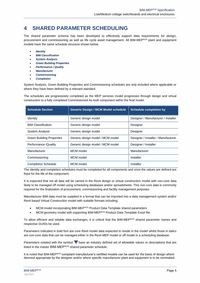
The shared parameter schema has been developed to effectively support data requirements for design,
procurement and commissioning as well as life cycle asset management. All BIM-MEPAUS plant and equipment
models have the same schedule structure shown below.
• Identity
• BIM Classification
• System Analysis
• Green Building Properties
• Performance / Quality
• Manufacturer
• Commissioning
• Completion
System Analysis, Green Building Properties and Commissioning schedules are only included where applicable or
where they have been defined by a relevant standard.
The schedules are progressively completed as the MEP services model progresses through design and virtual
construction to a fully completed Commissioned As-built component within the final model.
Schedule Section Generic Design / MCM Model schedule Schedule completion by
Identity Generic design model Designer / Manufacturer / Installer
BIM Classification Generic design model Designer
System Analysis Generic design model Designer
Green Building Properties Generic design model / MCM model Designer / Installer / Manufacturer
Performance /Quality Generic design model / MCM model Designer / Installer
Manufacturer MCM model Manufacturer
Commissioning MCM model Installer
Completion Schedule MCM model Installer
The identity and completion schedules must be completed for all components and once the values are defined are
fixed for the life of the component.
It is expected that not all data will be carried in the Revit design or virtual construction model with non-core data
likely to be managed off model using scheduling databases and/or spreadsheets. This non-core data is commonly
required for the finalization of procurement, commissioning and facility management purposes.
Manufacturer BIM data must be supplied in a format that can be imported into a data management system and/or
Revit based Virtual Construction model with suitable formats including:
• MCM model incorporating BIM-MEPAUS Product Data Template shared parameters
• MCM geometry model with supporting BIM-MEPAUS Product Data Template Excel file.
To allow efficient and reliable data exchanges, it is critical that the BIM-MEPAUS shared parameter names and
respective GUIDs be used.
Parameters indicated in bold font are core Revit model data expected to reside in the model whilst those in italics
are non-core data that can be managed either in the Revit MEP model or off model in a scheduling database.
Parameters notated with the symbol have an industry defined set of allowable values or descriptions that are
listed in the master BIM-MEPAUS shared parameter schedule.
It is noted that BIM-MEPAUS compliant manufacturer’s certified models can be used for the basis of design where deemed appropriate by the designer and/or where specific manufacturer plant and equipment is to be nominated.
BIM-MEPAUS Specification
Low/Medium voltage switchboards and electrical enclosures
BIM-MEPAUS Page 6
July 2017
5 SWITCHBOARD SPECIFICATION
The following guidance has been developed through the industry consultation process as particular areas requiring
focus during the completion of the switchboard quality/performance schedules.
5.1 Types of Switchboards and Enclosures
Main Switchboard (MSB)
The Main Switchboard is the location of the electrical installation main switch/isolator and electrical installation
Multiple Earth Neutral (MEN) link. The MSB will also contain a distribution section for power distribution typically to
sub distribution boards.
Distribution Switchboards (DB)
Distribution Boards are downstream of a MSB and provide power distribution to other downstream distribution
boards and/or final circuits typically of a common system.
Service Switchboards
These can include switchboards for specialty equipment such as mechanical motors, lift services or lighting control.
Electrical Enclosures
These can include electrical enclosures and cabinets for electrical equipment such as Tee Off boxes.
5.2 Switchboard Classifications
Ingress Protection (IP) Rating
All switchboards are to be given a formal rating for ingress protection as defined in international standard AS 60529.
This rating describes how resistant to penetration for water, dust and impact (IK rating) the switchboard is.
Areas for consideration when specifying a switchboard IP rating include the following:
• Exposure to natural elements (sun, rain, etc)
• Exposure to introduced elements (plantrooms, hazardous areas, etc)
Segregation Form Factor
All switchboards are specified with a form factor of segregation between the internal panels making up the
switchboard as per Australian Standard AS 61439. Internal segregation is important within a switchboard to protect
an operator from contact with live parts and reducing the probability of an arc fault.
Segregation can be achieved by two methods:
• Providing physical barriers or partitions between units
• Providing housing, insulation or shrouds to individual functional units or busbars
Segregation form factor varies from Form 1 to Form 4, each form factor increasing the level of segregation with
Form 1 having no internal separation.
Cable Entry/Exit
Depending on the installation location and environment, switchboards can be specified to have varying locations
for cable entry and exit. Typically cable entry/exits are either top or bottom, with rear openings specified when
required.
The location of cable entry/exit effects the physical dimensions of the switchboard, building penetrations, cable trays
and the arrangement of the internal switchgear. Clearances around cable entry/exits must also be considered in
the design stage to allow for cable reticulation and bend radius.
5.3 Access Clearance Zones
All switchboards are required by AS3000 to be arranged so that they provide a clearance zone for operators.
Sufficient switchboard access is considered to be an unimpeded space of at least 0.6m around switchboards with
switchgear doors in any position and large circuit-breakers racked out.
BIM-MEPAUS Specification
Low/Medium voltage switchboards and electrical enclosures
BIM-MEPAUS Page 7
July 2017
The maintenance clearance zone is therefore determined in part by the door/panel type that may be either hinged,
panel or escutcheon type.
Main Switchboards may also require rear access depending on their design.
5.4 Smoke Seals
Smoke seals typically consist of a neoprene gasket around the inside trim of the switchboard providing a smoke
seal when the doors are closed.
The Building Code of Australia (BCA) requires any switchboard installed in any corridor, hallway, lobby or the like
leading to a required exit to be enclosed by non-combustible construction with openings suitably sealed against
smoke spreading from the enclosure.
5.5 Switchboard Sizing
There are many factors that ultimately determine the overall switchboard size including form of connection, number
and size of circuits and internal bus/bar and wiring configuration.
Main switchboard general sizing guidelines are provided for preliminary spatial planning only:
• Incoming Supply 760mm
• Up to 10 outgoing circuits <250 AMP per 950mm section
• Air Circuit Breakers maximum of 2 per 760mm section.
5.6 Switchboard Panel Scheduling
The REVIT functionality of Switchboard Panel Scheduling is a key tool for retrieving design information from the
model. This section lists the parameters required for default panel schedules.
Switchboard Parameters
• Panel Name
• Location
• System served, zone served
• Power source (mains, generator, UPS, CoGen, PV, etc)
• Supply voltage rating, supply current rating, supply phase
• Fault rating
Circuit Parameters
• Circuit reference
• Circuit description
• Protection device description
• Protection device rating
• Total circuit load
• Cable size
BIM-MEPAUS Specification
Low/Medium voltage switchboards and electrical enclosures
BIM-MEPAUS Page 8
July 2017
6 REVIT FUNCTIONALITY
6.1 Category Classification
All switchboard families are designated in Revit MEP as electrical equipment.
6.2 Functional Type and Sub-type
The design and manufacture models functional type and sub-type are:
• Functional Type : MSB
DB
SB
EE
• Sub Type : FloorMounted
SurfaceMounted
RecessMounted
6.3 Family Naming Syntax
The switchboard family naming convention is as follows
Format:
Generic Design : <Functional Type>_< Sub-Functional Type>_<Generic>_<BMA>
MCM : <Functional Type>_< Sub-Functional Type>_<ManufacturerName>_<Type Descriptor>
Example family names:
Generic Design Model
LV/MV/MSB_FloorMounted_Generic_IFM
Manufacturer Certified Model
LV/MV/DB_WallMounted_ManufacturerName_Model Name 400AMP
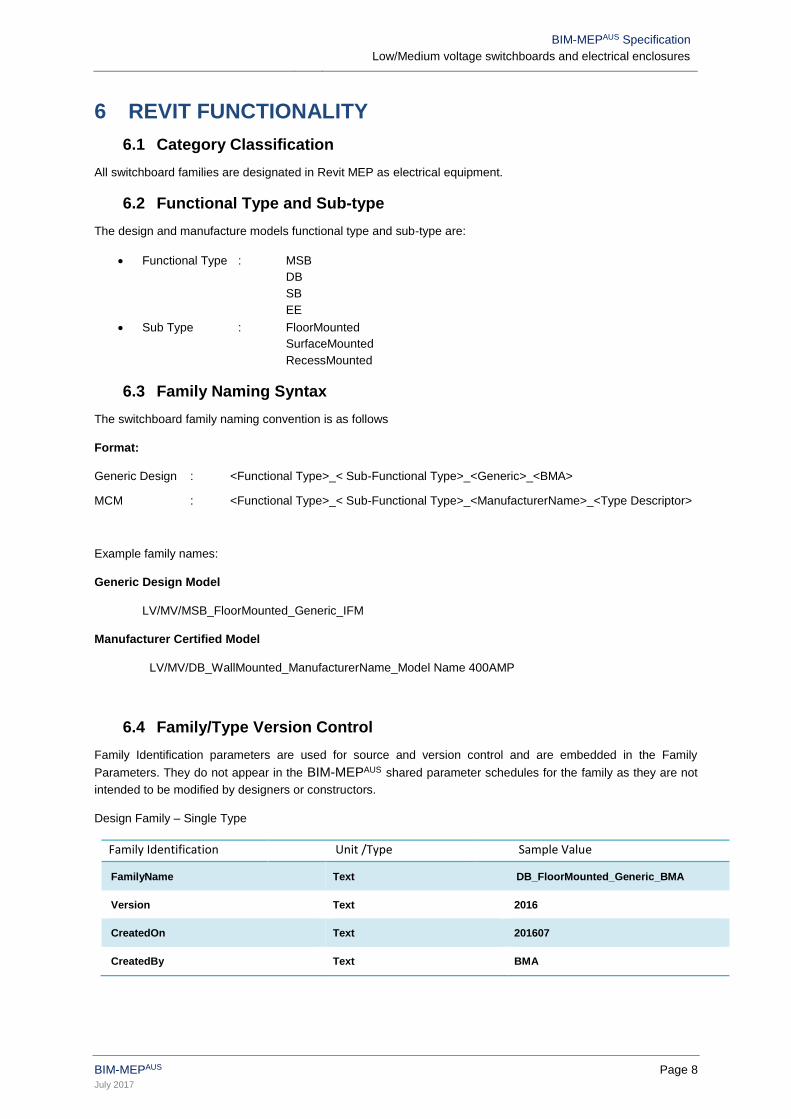
6.4 Family/Type Version Control
Family Identification parameters are used for source and version control and are embedded in the Family
Parameters. They do not appear in the BIM-MEPAUS shared parameter schedules for the family as they are not
intended to be modified by designers or constructors.
Design Family – Single Type
Family Identification Unit /Type Sample Value
FamilyName Text DB_FloorMounted_Generic_BMA
Version Text 2016
CreatedOn Text 201607
CreatedBy Text BMA
BIM-MEPAUS Specification
Low/Medium voltage switchboards and electrical enclosures
BIM-MEPAUS Page 9
July 2017
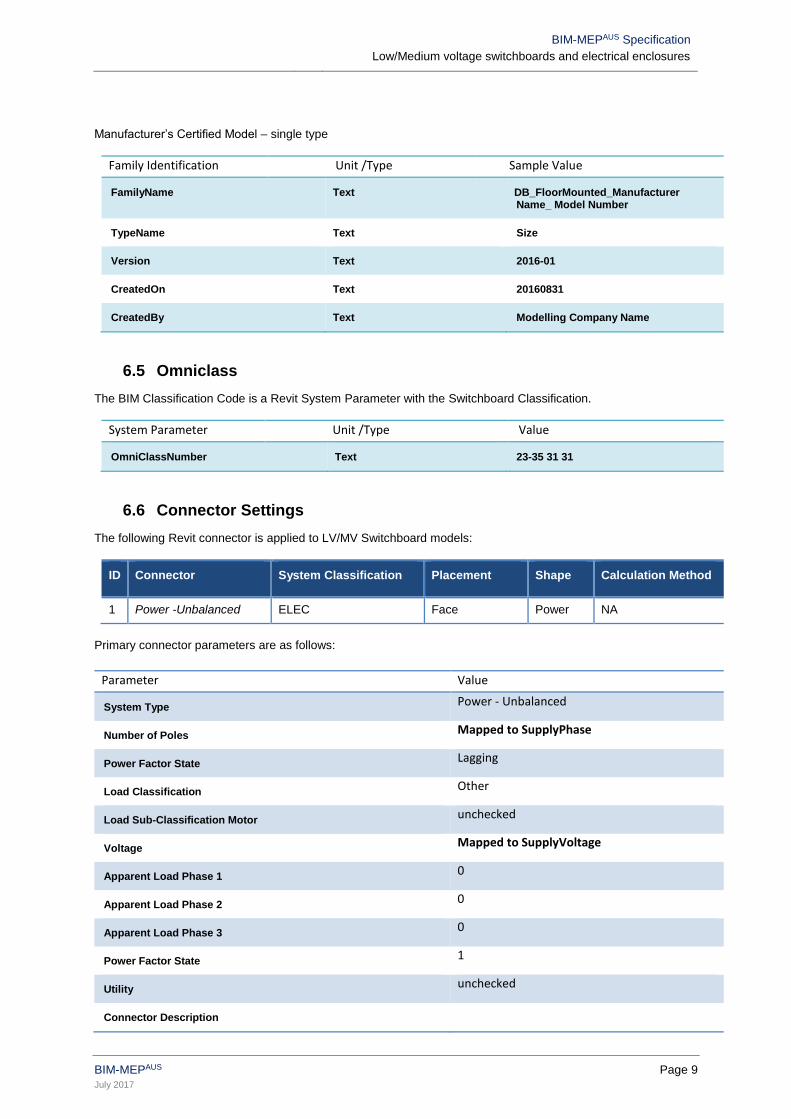
Manufacturer’s Certified Model – single type
Family Identification Unit /Type Sample Value
FamilyName Text DB_FloorMounted_Manufacturer Name_ Model Number
TypeName Text Size
Version Text 2016-01
CreatedOn Text 20160831
CreatedBy Text Modelling Company Name
6.5 Omniclass
The BIM Classification Code is a Revit System Parameter with the Switchboard Classification.
System Parameter Unit /Type Value
OmniClassNumber Text 23-35 31 31
6.6 Connector Settings
The following Revit connector is applied to LV/MV Switchboard models:
ID Connector System Classification Placement Shape Calculation Method
1 Power -Unbalanced ELEC Face Power NA
Primary connector parameters are as follows:
Parameter Value
System Type Power - Unbalanced
Number of Poles Mapped to SupplyPhase
Power Factor State Lagging
Load Classification Other
Load Sub-Classification Motor unchecked
Voltage Mapped to SupplyVoltage
Apparent Load Phase 1 0
Apparent Load Phase 2 0
Apparent Load Phase 3 0
Power Factor State 1
Utility unchecked
Connector Description
BIM-MEPAUS Specification
Low/Medium voltage switchboards and electrical enclosures
BIM-MEPAUS Page 10
July 2017
6.7 Family Geometry
Family geometry is controlled by instance based parameters with the intention that the modeller should not need to
modify the geometry of generic design models or Manufacturer’s Certified Models.
It is noted that the Family Dimension Parameters are used to schedule those parameters that define the type (size
or capacity), with all detailed geometry dimensions listed separately under the Geometry Grouping.
Critical dimensions in relation to the model geometry are:
• Switchboard height, width and depth
• Panel opening size and type (Door size and locations)
• Maintenance Clearance.
• Fixing method (Wall mounted, wall recessed, free standing)
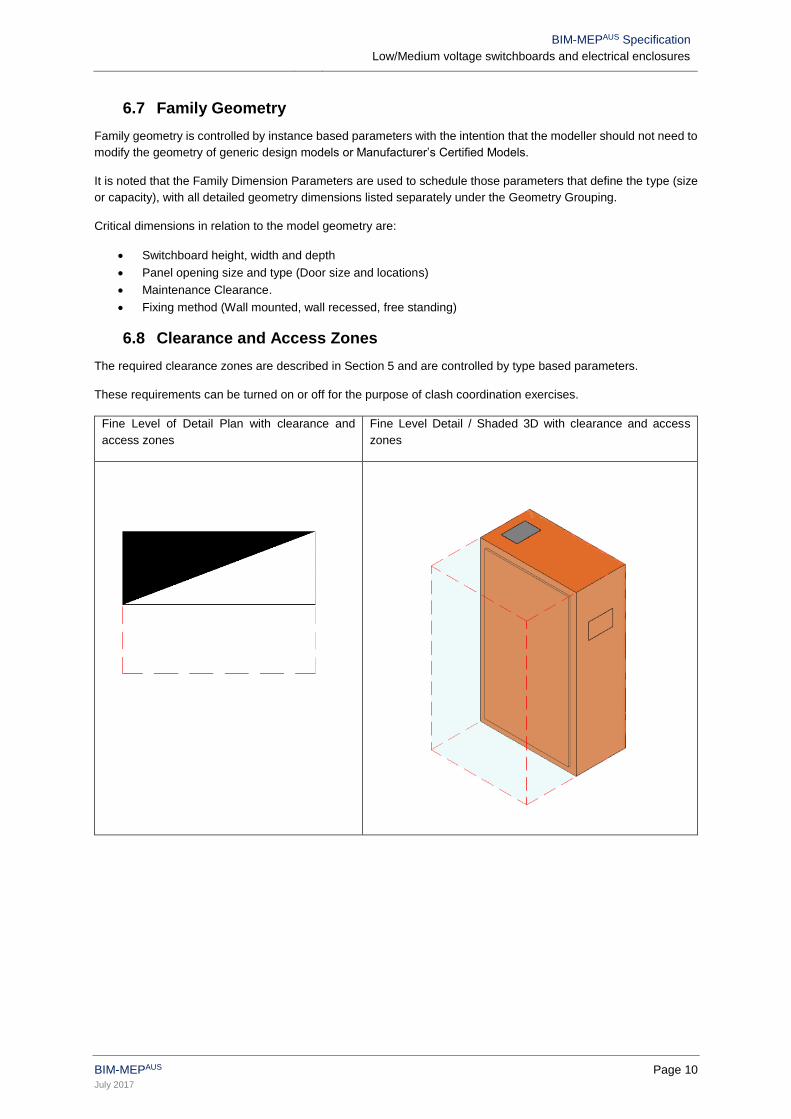
6.8 Clearance and Access Zones
The required clearance zones are described in Section 5 and are controlled by type based parameters.
These requirements can be turned on or off for the purpose of clash coordination exercises.
Fine Level of Detail Plan with clearance and
access zones
Fine Level Detail / Shaded 3D with clearance and access
zones
BIM-MEPAUS Specification
Low/Medium voltage switchboards and electrical enclosures
BIM-MEPAUS Page 11
July 2017
7 PARAMETER SCHEDULES
The schedule structure and parameters have been developed to meet the needs of the BIM-MEPAUS integrated
project delivery workflows as well as support future asset life cycle management requirements. The Product Data
Templates form a subset of the overall shared parameter scheme.
Refer to Section 4 - Shared Parameter Scheduling for a detailed overview of the intended use and application of
the schedules.
Parameter fields indicated in black bold text are included in the Product Data Template with the Design Model
Schedule being provided with a sub-set of these parameters detailed in Section 7.9 Generic Design Model
Schedule.
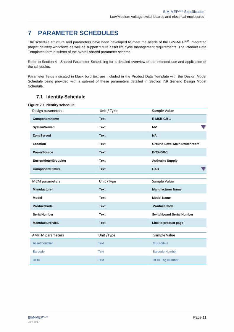
7.1 Identity Schedule
Figure 7.1 Identity schedule
Design parameters Unit / Type Sample Value
ComponentName Text E-MSB-GR-1
SystemServed Text MV
ZoneServed Text NA
Location Text Ground Level Main Switchroom
PowerSource Text E-TX-GR-1
EnergyMeterGrouping Text Authority Supply
ComponentStatus Text CAB
MCM parameters Unit /Type Sample Value
Manufacturer Text Manufacturer Name
Model Text Model Name
ProductCode Text Product Code
SerialNumber Text Switchboard Serial Number
ManufacturerURL Text Link to product page
AM/FM parameters Unit /Type Sample Value
AssetIdentifier Text MSB-GR-1
Barcode Text Barcode Number
RFID Text RFID Tag Number
BIM-MEPAUS Specification
Low/Medium voltage switchboards and electrical enclosures
BIM-MEPAUS Page 12
July 2017
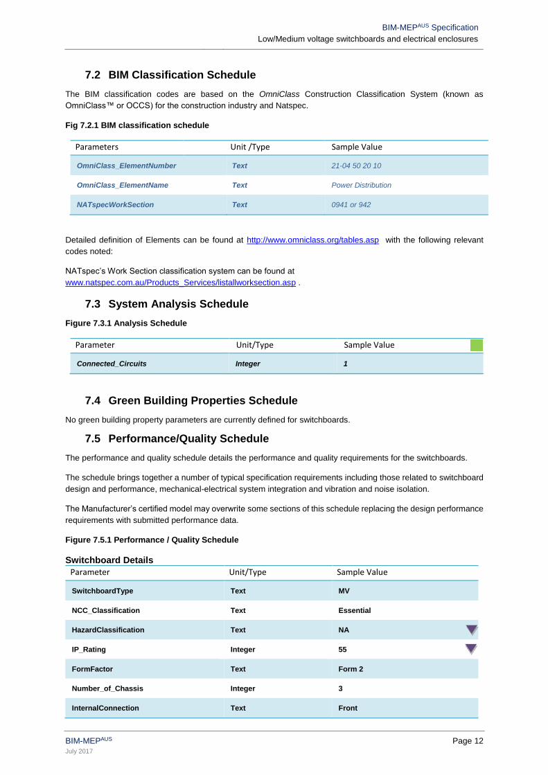
7.2 BIM Classification Schedule
The BIM classification codes are based on the OmniClass Construction Classification System (known as
OmniClass™ or OCCS) for the construction industry and Natspec.
Fig 7.2.1 BIM classification schedule
Parameters Unit /Type Sample Value
OmniClass_ElementNumber Text 21-04 50 20 10
OmniClass_ElementName Text Power Distribution
NATspecWorkSection Text 0941 or 942
Detailed definition of Elements can be found at http://www.omniclass.org/tables.asp with the following relevant
codes noted:
NATspec’s Work Section classification system can be found at
www.natspec.com.au/Products_Services/listallworksection.asp .
7.3 System Analysis Schedule
Figure 7.3.1 Analysis Schedule
Parameter Unit/Type Sample Value
Connected_Circuits Integer 1
7.4 Green Building Properties Schedule
No green building property parameters are currently defined for switchboards.
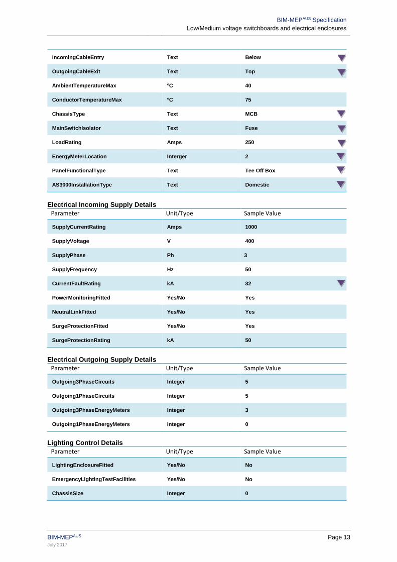
7.5 Performance/Quality Schedule
The performance and quality schedule details the performance and quality requirements for the switchboards.
The schedule brings together a number of typical specification requirements including those related to switchboard
design and performance, mechanical-electrical system integration and vibration and noise isolation.
The Manufacturer’s certified model may overwrite some sections of this schedule replacing the design performance
requirements with submitted performance data.
Figure 7.5.1 Performance / Quality Schedule
Switchboard Details
Parameter Unit/Type Sample Value
SwitchboardType Text MV
NCC_Classification Text Essential
HazardClassification Text NA
IP_Rating Integer 55
FormFactor Text Form 2
Number_of_Chassis Integer 3
InternalConnection Text Front
BIM-MEPAUS Specification
Low/Medium voltage switchboards and electrical enclosures
BIM-MEPAUS Page 13
July 2017
IncomingCableEntry Text Below
OutgoingCableExit Text Top
AmbientTemperatureMax oC 40
ConductorTemperatureMax oC 75
ChassisType Text MCB
MainSwitchIsolator Text Fuse
LoadRating Amps 250
EnergyMeterLocation Interger 2
PanelFunctionalType Text Tee Off Box
AS3000InstallationType Text Domestic
Electrical Incoming Supply Details
Parameter Unit/Type Sample Value
SupplyCurrentRating Amps 1000
SupplyVoltage V 400
SupplyPhase Ph 3
SupplyFrequency Hz 50
CurrentFaultRating kA 32
PowerMonitoringFitted Yes/No Yes
NeutralLinkFitted Yes/No Yes
SurgeProtectionFitted Yes/No Yes
SurgeProtectionRating kA 50
Electrical Outgoing Supply Details
Parameter Unit/Type Sample Value
Outgoing3PhaseCircuits Integer 5
Outgoing1PhaseCircuits Integer 5
Outgoing3PhaseEnergyMeters Integer 3
Outgoing1PhaseEnergyMeters Integer 0
Lighting Control Details
Parameter Unit/Type Sample Value
LightingEnclosureFitted Yes/No No
EmergencyLightingTestFacilities Yes/No No
ChassisSize Integer 0
BIM-MEPAUS Specification
Low/Medium voltage switchboards and electrical enclosures
BIM-MEPAUS Page 14
July 2017
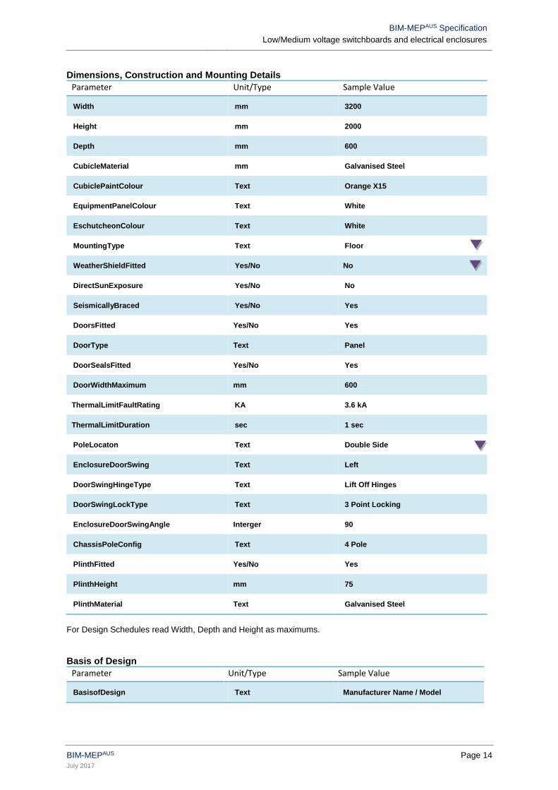
Dimensions, Construction and Mounting Details
Parameter Unit/Type Sample Value
Width mm 3200
Height mm 2000
Depth mm 600
CubicleMaterial mm Galvanised Steel
CubiclePaintColour Text Orange X15
EquipmentPanelColour Text White
EschutcheonColour Text White
MountingType Text Floor
WeatherShieldFitted Yes/No No
DirectSunExposure Yes/No No
SeismicallyBraced Yes/No Yes
DoorsFitted Yes/No Yes
DoorType Text Panel
DoorSealsFitted Yes/No Yes
DoorWidthMaximum mm 600
ThermalLimitFaultRating KA 3.6 kA
ThermalLimitDuration sec 1 sec
PoleLocaton Text Double Side
EnclosureDoorSwing Text Left
DoorSwingHingeType Text Lift Off Hinges
DoorSwingLockType Text 3 Point Locking
EnclosureDoorSwingAngle Interger 90
ChassisPoleConfig Text 4 Pole
PlinthFitted Yes/No Yes
PlinthHeight mm 75
PlinthMaterial Text Galvanised Steel
For Design Schedules read Width, Depth and Height as maximums.
Basis of Design
Parameter Unit/Type Sample Value
BasisofDesign Text Manufacturer Name / Model
BIM-MEPAUS Specification
Low/Medium voltage switchboards and electrical enclosures
BIM-MEPAUS Page 15
July 2017
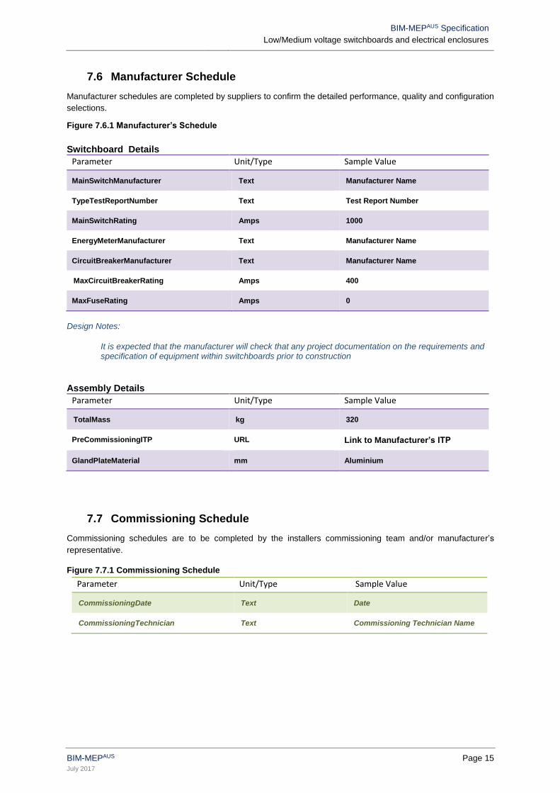
7.6 Manufacturer Schedule
Manufacturer schedules are completed by suppliers to confirm the detailed performance, quality and configuration
selections.
Figure 7.6.1 Manufacturer’s Schedule
Switchboard Details
Parameter Unit/Type Sample Value
MainSwitchManufacturer Text Manufacturer Name
TypeTestReportNumber Text Test Report Number
MainSwitchRating Amps 1000
EnergyMeterManufacturer Text Manufacturer Name
CircuitBreakerManufacturer Text Manufacturer Name
MaxCircuitBreakerRating Amps 400
MaxFuseRating Amps 0
Design Notes:
It is expected that the manufacturer will check that any project documentation on the requirements and specification of equipment within switchboards prior to construction
Assembly Details
Parameter Unit/Type Sample Value
TotalMass kg 320
PreCommissioningITP URL Link to Manufacturer’s ITP
GlandPlateMaterial mm Aluminium
7.7 Commissioning Schedule
Commissioning schedules are to be completed by the installers commissioning team and/or manufacturer’s
representative.
Figure 7.7.1 Commissioning Schedule
Parameter Unit/Type Sample Value
CommissioningDate Text Date
CommissioningTechnician Text Commissioning Technician Name
BIM-MEPAUS Specification
Low/Medium voltage switchboards and electrical enclosures
BIM-MEPAUS Page 16
July 2017
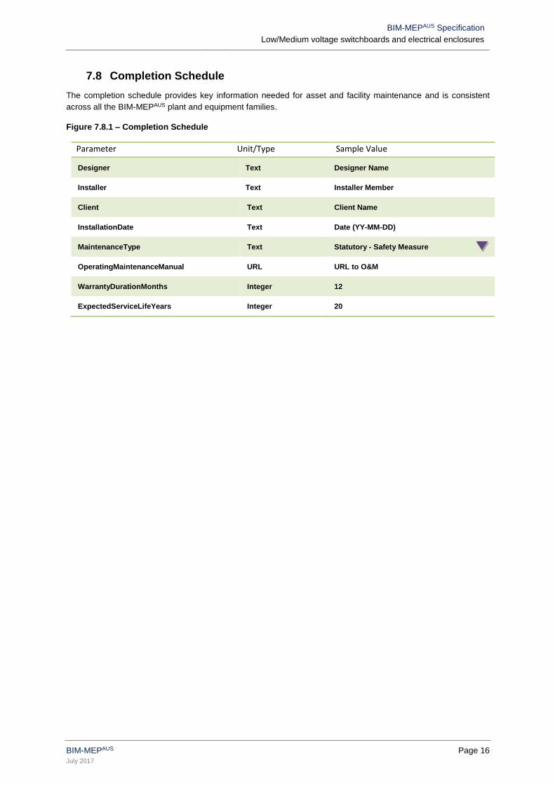
7.8 Completion Schedule
The completion schedule provides key information needed for asset and facility maintenance and is consistent
across all the BIM-MEPAUS plant and equipment families.
Figure 7.8.1 – Completion Schedule
Parameter Unit/Type Sample Value
Designer Text Designer Name
Installer Text Installer Member
Client Text Client Name
InstallationDate Text Date (YY-MM-DD)
MaintenanceType Text Statutory - Safety Measure
OperatingMaintenanceManual URL URL to O&M
WarrantyDurationMonths Integer 12
ExpectedServiceLifeYears Integer 20
BIM-MEPAUS Specification
Low/Medium voltage switchboards and electrical enclosures
BIM-MEPAUS Page 17
July 2017
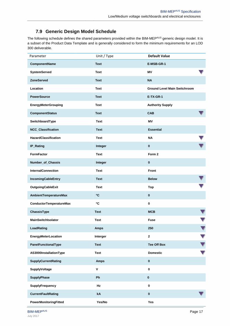
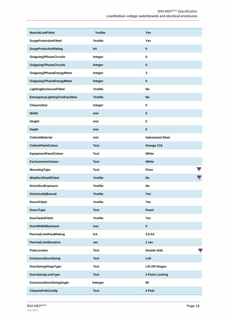
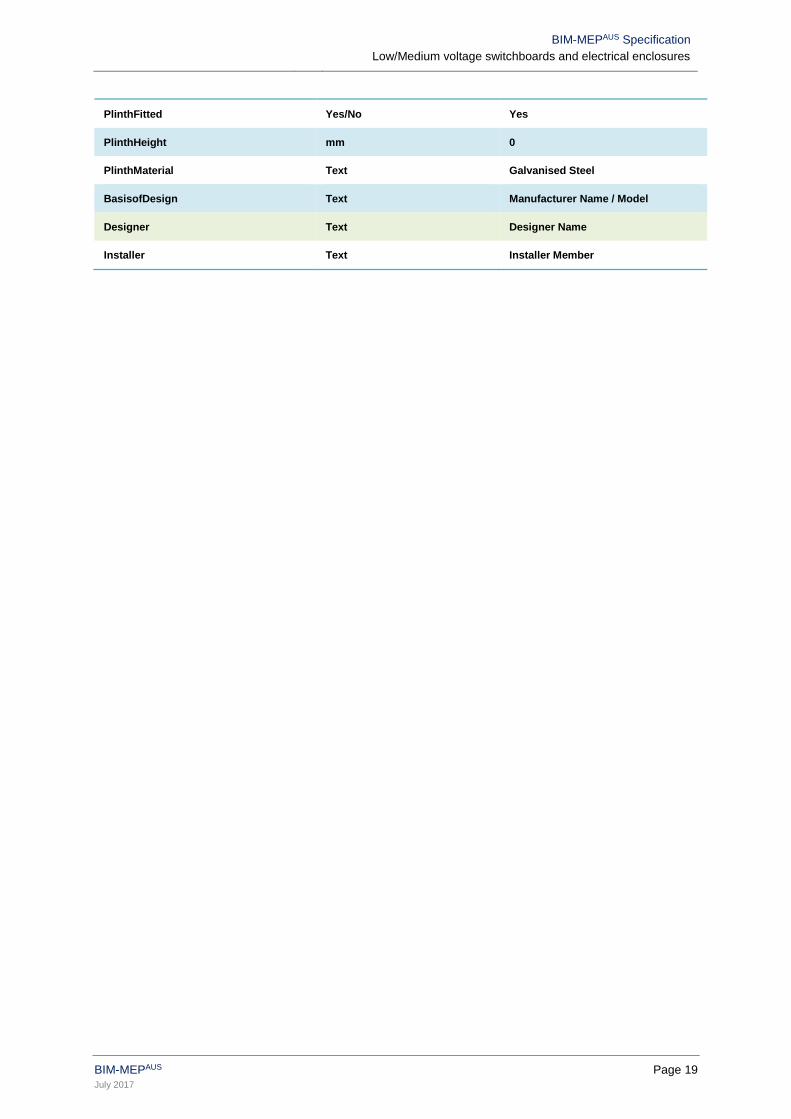
7.9 Generic Design Model Schedule
The following schedule defines the shared parameters provided within the BIM-MEPAUS generic design model. It is
a subset of the Product Data Template and is generally considered to form the minimum requirements for an LOD
300 deliverable.
Parameter Unit / Type Default Value
ComponentName Text E-MSB-GR-1
SystemServed Text MV
ZoneServed Text NA
Location Text Ground Level Main Switchroom
PowerSource Text E-TX-GR-1
EnergyMeterGrouping Text Authority Supply
ComponentStatus Text CAB
SwitchboardType Text MV
NCC_Classification Text Essential
HazardClassification Text NA
IP_Rating Integer 0
FormFactor Text Form 2
Number_of_Chassis Integer 0
InternalConnection Text Front
IncomingCableEntry Text Below
OutgoingCableExit Text Top
AmbientTemperatureMax oC 0
ConductorTemperatureMax oC 0
ChassisType Text MCB
MainSwitchIsolator Text Fuse
LoadRating Amps 250
EnergyMeterLocation Interger 2
PanelFunctionalType Text Tee Off Box
AS3000InstallationType Text Domestic
SupplyCurrentRating Amps 0
SupplyVoltage V 0
SupplyPhase Ph 0
SupplyFrequency Hz 0
CurrentFaultRating kA 0
PowerMonitoringFitted Yes/No Yes
BIM-MEPAUS Specification
Low/Medium voltage switchboards and electrical enclosures
BIM-MEPAUS Page 18
July 2017
NeutralLinkFitted Yes/No Yes
SurgeProtectionFitted Yes/No Yes
SurgeProtectionRating kA 0
Outgoing3PhaseCircuits Integer 0
Outgoing1PhaseCircuits Integer 0
Outgoing3PhaseEnergyMeter Integer 3
Outgoing1PhaseEnergyMeter Integer 0
LightingEnclosureFitted Yes/No No
EmergencyLightingTestFacilities Yes/No No
ChassisSize Integer 0
Width mm 0
Height mm 0
Depth mm 0
CubicleMaterial mm Galvanised Steel
CubiclePaintColour Text Orange X15
EquipmentPanelColour Text White
EschutcheonColour Text White
MountingType Text Floor
WeatherShieldFitted Yes/No No
DirectSunExposure Yes/No No
SeismicallyBraced Yes/No Yes
DoorsFitted Yes/No Yes
DoorsType Text Panel
DoorSealsFitted Yes/No Yes
DoorWidthMaximum mm 0
ThermalLimitFaultRating KA 3.6 kA
ThermalLimitDuration sec 1 sec
PoleLocaton Text Double Side
EnclosureDoorSwing Text Left
DoorSwingHingeType Text Lift Off Hinges
DoorSwingLockType Text 3 Point Locking
EnclosureDoorSwingAngle Interger 90
ChassisPoleConfig Text 4 Pole
BIM-MEPAUS Specification
Low/Medium voltage switchboards and electrical enclosures
BIM-MEPAUS Page 19
July 2017
PlinthFitted Yes/No Yes
PlinthHeight mm 0
PlinthMaterial Text Galvanised Steel
BasisofDesign Text Manufacturer Name / Model
Designer Text Designer Name
Installer Text Installer Member
BIM-MEPAUS Specification
Low/Medium voltage switchboards and electrical enclosures
BIM-MEPAUS Page 20
July 2017
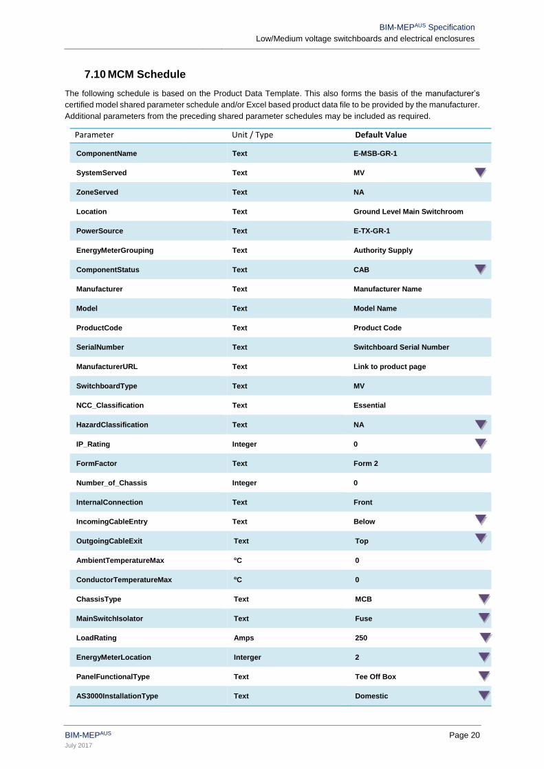
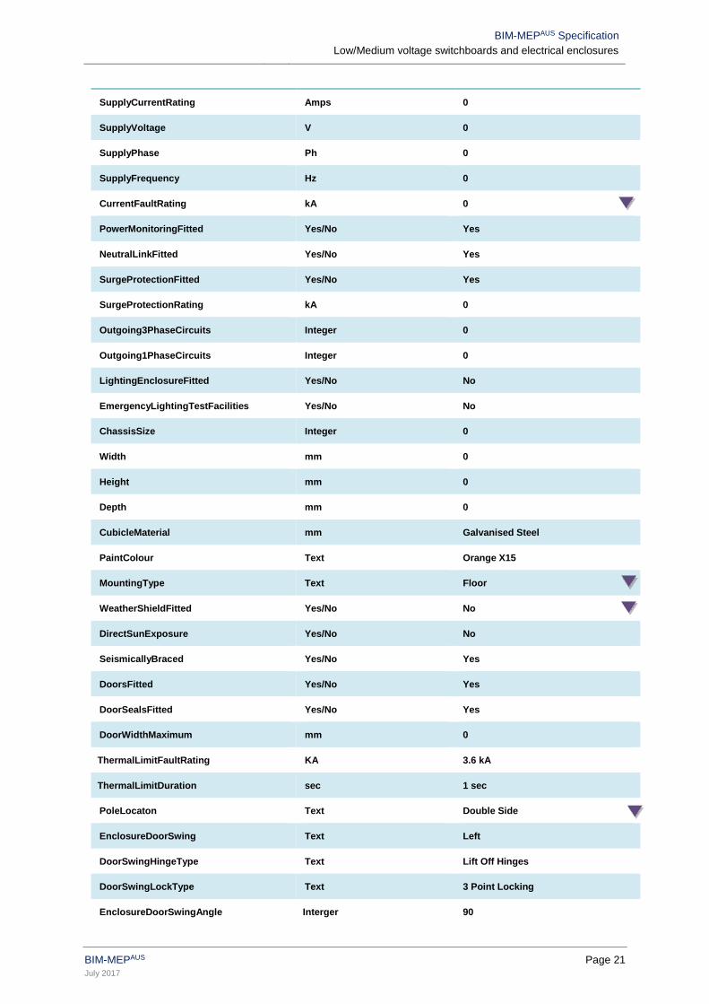
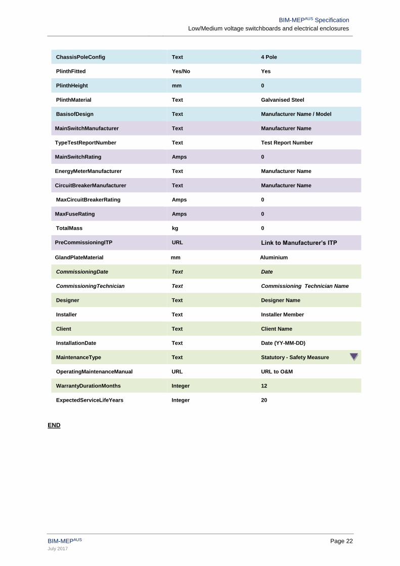
7.10 MCM Schedule
The following schedule is based on the Product Data Template. This also forms the basis of the manufacturer’s
certified model shared parameter schedule and/or Excel based product data file to be provided by the manufacturer.
Additional parameters from the preceding shared parameter schedules may be included as required.
Parameter Unit / Type Default Value
ComponentName Text E-MSB-GR-1
SystemServed Text MV
ZoneServed Text NA
Location Text Ground Level Main Switchroom
PowerSource Text E-TX-GR-1
EnergyMeterGrouping Text Authority Supply
ComponentStatus Text CAB
Manufacturer Text Manufacturer Name
Model Text Model Name
ProductCode Text Product Code
SerialNumber Text Switchboard Serial Number
ManufacturerURL Text Link to product page
SwitchboardType Text MV
NCC_Classification Text Essential
HazardClassification Text NA
IP_Rating Integer 0
FormFactor Text Form 2
Number_of_Chassis Integer 0
InternalConnection Text Front
IncomingCableEntry Text Below
OutgoingCableExit Text Top
AmbientTemperatureMax oC 0
ConductorTemperatureMax oC 0
ChassisType Text MCB
MainSwitchIsolator Text Fuse
LoadRating Amps 250
EnergyMeterLocation Interger 2
PanelFunctionalType Text Tee Off Box
AS3000InstallationType Text Domestic
BIM-MEPAUS Specification
Low/Medium voltage switchboards and electrical enclosures
BIM-MEPAUS Page 21
July 2017
SupplyCurrentRating Amps 0
SupplyVoltage V 0
SupplyPhase Ph 0
SupplyFrequency Hz 0
CurrentFaultRating kA 0
PowerMonitoringFitted Yes/No Yes
NeutralLinkFitted Yes/No Yes
SurgeProtectionFitted Yes/No Yes
SurgeProtectionRating kA 0
Outgoing3PhaseCircuits Integer 0
Outgoing1PhaseCircuits Integer 0
LightingEnclosureFitted Yes/No No
EmergencyLightingTestFacilities Yes/No No
ChassisSize Integer 0
Width mm 0
Height mm 0
Depth mm 0
CubicleMaterial mm Galvanised Steel
PaintColour Text Orange X15
MountingType Text Floor
WeatherShieldFitted Yes/No No
DirectSunExposure Yes/No No
SeismicallyBraced Yes/No Yes
DoorsFitted Yes/No Yes
DoorSealsFitted Yes/No Yes
DoorWidthMaximum mm 0
ThermalLimitFaultRating KA 3.6 kA
ThermalLimitDuration sec 1 sec
PoleLocaton Text Double Side
EnclosureDoorSwing Text Left
DoorSwingHingeType Text Lift Off Hinges
DoorSwingLockType Text 3 Point Locking
EnclosureDoorSwingAngle Interger 90
BIM-MEPAUS Specification
Low/Medium voltage switchboards and electrical enclosures
BIM-MEPAUS Page 22
July 2017
ChassisPoleConfig Text 4 Pole
PlinthFitted Yes/No Yes
PlinthHeight mm 0
PlinthMaterial Text Galvanised Steel
BasisofDesign Text Manufacturer Name / Model
MainSwitchManufacturer Text Manufacturer Name
TypeTestReportNumber Text Test Report Number
MainSwitchRating Amps 0
EnergyMeterManufacturer Text Manufacturer Name
CircuitBreakerManufacturer Text Manufacturer Name
MaxCircuitBreakerRating Amps 0
MaxFuseRating Amps 0
TotalMass kg 0
PreCommissioningITP URL Link to Manufacturer’s ITP
GlandPlateMaterial mm Aluminium
CommissioningDate Text Date
CommissioningTechnician Text Commissioning Technician Name
Designer Text Designer Name
Installer Text Installer Member
Client Text Client Name
InstallationDate Text Date (YY-MM-DD)
MaintenanceType Text Statutory - Safety Measure
OperatingMaintenanceManual URL URL to O&M
WarrantyDurationMonths Integer 12
ExpectedServiceLifeYears Integer 20
END