Embed Size (px)
Citation preview
_____________________________________________
Telecommunications and 211 – A Primer
______________________________________________________ May, 2002 Report prepared by the Telecommunications and Information Policy Institute (TIPI) University of Texas at Austin, Austin, TX 78712 (512) 471-5826 www.utexas.edu/research.tipi Erich Pelletier, Research Associate Dr. Sharon Strover, Director
INTRODUCTION: 211 BACKGROUND AND HISTORY........................................ 1
PART I: BASIC TELECOMMUNICATIONS IN THE PUBLIC SWITCHED TELEPHONE NETWORK ............................................................................................. 3
HOW DO TELEPHONE NETWORKS OPERATE?.................................................................... 3 WHAT IS A “LATA” AND WHAT ISSUES DO LATA STRUCTURES PRESENT TO 211 SYSTEMS? ........................................................................................................................ 6 WHAT ARE N11 SERVICES? ............................................................................................. 7 WHAT IS N11 TO SEVEN- OR TEN-DIGIT TRANSLATION, AND WHAT ARE ‘POINT-TO’ NUMBERS? ....................................................................................................................... 8 SHOULD MY 211 SERVICE PLAN TO MAINTAIN A TOLL-FREE POINT-TO NUMBER?............. 8 WHAT ARE THE ISSUES FACED IN PROVIDING CELLULAR TELEPHONE ACCESS TO 211 SERVICES?........................................................................................................................ 9 WHAT ARE THE ISSUES FACED IN PROVIDING PUBLIC TELEPHONE (PAYPHONE) ACCESS TO 211 SERVICES?............................................................................................................... 11
PART II: BASIC TELECOMMUNICATIONS IN 211 CALL CENTERS AND NETWORKS................................................................................................................... 13
WHAT ARE THE BASIC TYPES OF NETWORKS THAT CAN BE UTILIZED IN 211 OPERATIONS?....................................................................................................................................... 13 WHAT ARE SOME OF THE BEST TECHNOLOGICAL OPTIONS FOR THE CONSTRUCTION OF 211 WIDE AREA NETWORKS?............................................................................................... 15 WHAT ADVANTAGES CAN VOICE CALLS-OVER-THE-INTERNET (VOIP OR VOICE OVER INTERNET PROTOCOL) PROVIDE TO 211 SERVICES?........................................................ 17 WHAT OPTIONS DO VARIOUS STATE-ADMINISTERED NETWORKS PROVIDE TO 211 OPERATORS IN TERMS OF NETWORKING A 211 SYSTEM WITH MULTIPLE CALL CENTERS?18 WHAT ARE THE MOST USEFUL TELECOMMUNICATIONS TECHNOLOGIES AVAILABLE FOR USE IN A 211 CALL CENTER? .......................................................................................... 18
PART III: THE TELECOMMUNICATIONS INDUSTRY, ITS REGULATORY APPARATUS, AND 211................................................................................................. 21
WHAT IS THE ROLE OF THE FEDERAL COMMUNICATIONS COMMISSION (FCC) IN 211 IMPLEMENTATION? ........................................................................................................ 21 WHAT IS THE ROLE OF STATE UTILITIES COMMISSIONS IN 211 IMPLEMENTATION?......... 21 WHAT IS A LOCAL EXCHANGE CARRIER (LEC), WHAT PART DO LECS PLAY IN 211 IMPLEMENTATION, AND WHAT IS THE DIFFERENCE BETWEEN AN ILEC AND A CLEC?.. 22 WHAT IS A “TARIFF”, AND HOW DOES IT FUNCTION WITH REGARD TO 211? .................. 23
CONCLUSION ............................................................................................................... 25
APPENDIX A: BANDWIDTHS OF VARIOUS INTERNET CONNECTION / NETWORK TYPES ....................................................................................................... 26
APPENDIX B: REFERENCES TO FURTHER TELECOMMUNICATIONS RESOURCES .................................................................................................................. 27

Figures FIGURE 1: THE SERVICE AREA OF A SINGLE CENTRAL OFFICE ............................................ 4 FIGURE 2: CONNECTIONS BETWEEN END USERS VIA LOCAL CENTRAL OFFICES .................. 5 FIGURE 3: CELLULAR TELEPHONE NETWORKS ................................................................. 10 FIGURE 4: LOCAL AREA NETWORKS AND WIDE AREA NETWORKS ................................... 14
ii
Introduction: 211 Background and History
U.S. residents in need of social service assistance ranging from domestic violence hotlines to elderly or homeless housing assistance to simple assistance in paying utility bills often are obliged to negotiate a labyrinthine system of referrals and misdirected inquiries before locating help. At times, assistance is never reached, even if it is available in the area. The common difficulties encountered by those in need in securing social service assistance and those desiring to provide it led to a nationwide effort to create a system of simple telephone access to health and human services. The utility of nationally ubiquitous three-digit dialing combinations - “abbreviated N11 services” - for emergency services (911) and directory assistance (411), as well as the growing use of non-emergency police services (311), led Information and Referral (I&R) representatives and organizing bodies to conclude that the public interest would best be served if the “211” dialing code was reserved for access to social service I&R services. Some early and exemplary use of 211 was demonstrated by the June, 1997 installation of a 211-based I&R service operated by the United Way of Metropolitan Atlanta. This system made use of an existing I&R service, its call center and expertise. The creation of United Way 211 in Atlanta was followed in 1999 by a similar, though statewide, system operated by the United Way of Connecticut and has been joined by a growing national movement of I&R services and coalitions interested in building similar systems. In May, 1998, the National 211 Collaborative, including the Alliance of Information and Referral Systems (AIRS), United Way of America, United Way 211 (Atlanta), United Way of Connecticut, the Florida Alliance of Information and Referral Services, Inc. (FLAIRS), and the Texas Information and Referral Network filed a petition with the Federal Communications Commission (FCC) requesting national assignment of 211 dialing codes for social service Information and Referral. Recognizing that N11 dialing codes are a scarce resource, the 211 Collaborative argued that a compelling public need exists for this use of 211 that is not satisfactorily met by existing 911, 411, or 311 services. The FCC ruled July 21, 2000 in favor of 211 proponents, declaring that this use of 211 best satisfies the public interest. Since the FCC ruling, efforts toward implementing 211 services have continued in some states and begun in many others, with widely varying results. Some 211-accessed I&R systems have become operational within a few months of initial efforts, while others have met considerable obstacles on many fronts, including challenges from within the I&R community, lack of support from state regulatory bodies, prohibitively high rates from Local Exchange Carriers (LECs) – local telephone companies – for delivery of 211 service, and opposition from other potential N11 service providers. To date, every operational 211 I&R service consists of a single, centralized call center servicing a locality (defined here as a metropolitan area or limited county grouping) or a very small state. Some locations, such as in Georgia, have approached statewide coverage with several call centers, but at this writing no multiple-call center system is yet fully “integrated” with regard to database sharing and administration. Many non-statewide 211 systems are designed with the express intention of “scaling up” to include greater geographic scope, often with the assumed goal of joining with other 211 providers to facilitate integrated statewide coverage. Currently, Connecticut’s Infoline is the sole statewide provider of 211-accessed I&R services, though most other providers’ implementation plans include statewide coverage as an eventual goal. In the course of developing operational 211 systems, providers of I&R services must familiarize themselves with the technical details of telecommunications services and their operation. Knowledge not only of how telephone systems operate on a basic technical level but also of the manner in which the telecommunications industry is organized and regulated is necessary when

211 implementation efforts reach the point of negotiations with LECs for provision of 211 service. Many I&R representatives face confusion and frustration when negotiating with LECs for 211 service, as a great deal of “industry language” is not necessarily clear when first encountered. Similarly, frustration and confusion can be experienced by LEC representatives when approached by potential 211 providers unfamiliar with the services and telecommunications infrastructure necessary to create a 211 network. If potential 211 providers can approach the LECs with prior knowledge not only of basic telecommunications but also of those specific services which will be needed in the creation of such networks, a great deal of confusion and potential “stalls” in negotiation can be eliminated. This document provides information on telecommunications systems and industries that is crucial for potential 211 providers to know when working to create operational 211 systems. As well, it provides information useful to telecommunications providers when first working with I&R service representatives concerning the level and type of services needed for the successful functioning of a 211 I&R system. At times, LEC representatives have overestimated the needs of 211 service providers (often believing, for example, that 211 systems will require capabilities equivalent to those of 911 systems). This, in turn, leads them to quote prices for the creation of 211 networks that appear exorbitant to potential 211 providers. In general, if all involved parties can reach an understanding regarding the required elements of a 211 system, such systems can be implemented more quickly and smoothly. This document is based on common questions that a potential 211 service provider may encounter when navigating the complex issues involved in establishing a viable 211 I&R service. It is divided into sections corresponding to several broad topics, each of which contains common questions pertaining to those topics. In many cases, the information presented here is general in nature. Those in need of more specific information, or information relating directly to individual 211 implementation efforts, should consult with another of this institute’s publications: “211 State by State: A Periodic Report on the National Implementation of Three Digit-Accessed Telephone Information and Referral Services.” This report can be obtained via the World Wide Web at <http://www.utexas.edu/research/tipi>. Please note that this document is not meant to be a comprehensive accounting of every telecommunications issue that a 211 provider may face. Rather, this document addresses some of the most common questions encountered by this research institute during the course of preparing previous reports pertaining to 211. Those in need of more detailed information should consult with the resources included in Appendix B. Some of the issues covered here are quite general and basic, while others are more particular and pertain more directly to 211.
2
Part I: Basic Telecommunications in the Public Switched Telephone Network Any 211 service must make use of the Public Switched Telephone Network (PSTN) to deliver 211 calls from the end user to the I&R call center. The PSTN is the telephone network that delivers local and long distance telephony services to customers worldwide. Many I&R providers encounter initial difficulty understanding the different components of the PSTN, how it operates, what companies administer it, and how to approach the establishment of 211 service in their area. This section outlines some of the basic technical issues concerning telephone networks and how these issues relate to 211 services.
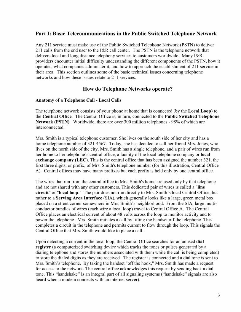
How do Telephone Networks operate? Anatomy of a Telephone Call - Local Calls The telephone network consists of your phone at home that is connected (by the Local Loop) to the Central Office. The Central Office is, in turn, connected to the Public Switched Telephone Network (PSTN). Worldwide, there are over 300 million telephones - 98% of which are interconnected. Mrs. Smith is a typical telephone customer. She lives on the south side of her city and has a home telephone number of 321-4567. Today, she has decided to call her friend Mrs. Jones, who lives on the north side of the city. Mrs. Smith has a single telephone, and a pair of wires run from her home to her telephone’s central office, a facility of the local telephone company or local exchange company (LEC). This is the central office that has been assigned the number 321, the first three digits, or prefix, of Mrs. Smith's telephone number (for this illustration, Central Office A). Central offices may have many prefixes but each prefix is held only by one central office. The wires that run from the central office to Mrs. Smith's home are used only by that telephone and are not shared with any other customers. This dedicated pair of wires is called a "line circuit" or "local loop." The pair does not run directly to Mrs. Smith’s local Central Office, but rather to a Serving Area Interface (SIA), which generally looks like a large, green metal box placed on a street corner somewhere in Mrs. Smith’s neighborhood. From the SIA, large multi-conductor bundles of wires (each wire a local loop) travel to Central Office A. The Central Office places an electrical current of about 48 volts across the loop to monitor activity and to power the telephone. Mrs. Smith initiates a call by lifting the handset off the telephone. This completes a circuit in the telephone and permits current to flow through the loop. This signals the Central Office that Mrs. Smith would like to place a call. Upon detecting a current in the local loop, the Central Office searches for an unused dial register (a computerized switching device which tracks the tones or pulses generated by a dialing telephone and stores the numbers associated with them while the call is being completed) to store the dialed digits as they are received. The register is connected and a dial tone is sent to Mrs. Smith’s telephone. By taking the handset "off the hook," Mrs. Smith has made a request for access to the network. The central office acknowledges this request by sending back a dial tone. This “handshake” is an integral part of all signaling systems (“handshake” signals are also heard when a modem connects with an internet server).
3

Upon hearing the dial tone, Mrs. Smith begins to dial 599-1234, the telephone number of Mrs. Jones. The dial register at the Central Office is now “full” (it has enough information to complete a connection) and contains the number 599-1234. Central Office A recognizes this number as belonging to Central Office number 599 (Central Office B). Since Central Office A cannot directly serve this number, it looks for a trunk (interoffice line) that will connect it with Central Office B.
Figure 1: The service area of a single Central Office
A Central Office can have up to 10,000 subscribers (for example, 321-0000 to 321-9999). Most have 4,000 to 5,000 subscribers connected to them. A trunk circuit provides a signal path between two Central Offices. Unlike a line circuit, or local loop, a trunk circuit is shared by many different subscribers, although only one uses a trunk circuit at any given time. There may be 100 or more trunk circuits between these Central Offices, and as one telephone call ends, a trunk circuit is released and made available for another call. Central Office A seizes the first available trunk it finds. This trunk is a dedicated path to Central Office B. When the trunk connection is established, Central Office B proceeds to make a connection with the appropriate local loop (to Mrs. Jones’ telephone). Beyond the trunk circuits that provide direct connections between central offices, the PSTN also utilizes simplified switching points called “local tandem switches”. Tandem switches provide an alternate means of routing calls between central offices and allow for greater network flexibility. If a central office determines that the trunk circuits connecting it to another central office are all being utilized, Mrs. Smith’s call may be routed through a tandem switch. In some areas, particularly those with low population densities, a tandem switch shared by several central offices may be the only connection between those central offices. The dedicated trunk circuits between central offices described above are generally used in areas where the density of
4
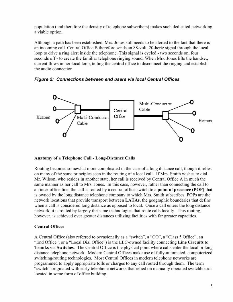
population (and therefore the density of telephone subscribers) makes such dedicated networking a viable option. Although a path has been established, Mrs. Jones still needs to be alerted to the fact that there is an incoming call. Central Office B therefore sends an 88-volt, 20-hertz signal through the local loop to drive a ring alert inside the telephone. This signal is cycled - two seconds on, four seconds off - to create the familiar telephone ringing sound. When Mrs. Jones lifts the handset, current flows in her local loop, telling the central office to disconnect the ringing and establish the audio connection. Figure 2: Connections between end users via local Central Offices
Anatomy of a Telephone Call - Long-Distance Calls Routing becomes somewhat more complicated in the case of a long distance call, though it relies on many of the same principles seen in the routing of a local call. If Mrs. Smith wishes to dial Mr. Wilson, who resides in another state, her call is received by Central Office A in much the same manner as her call to Mrs. Jones. In this case, however, rather than connecting the call to an inter-office line, the call is routed by a central office switch to a point of presence (POP) that is owned by the long distance telephone company to which Mrs. Smith subscribes. POPs are the network locations that provide transport between LATAs, the geographic boundaries that define when a call is considered long distance as opposed to local. Once a call enters the long distance network, it is routed by largely the same technologies that route calls locally. This routing, however, is achieved over greater distances utilizing facilities with far greater capacities. Central Offices A Central Office (also referred to occasionally as a “switch”, a “CO”, a “Class 5 Office”, an “End Office”, or a “Local Dial Office”) is the LEC-owned facility connecting Line Circuits to Trunks via Switches. The Central Office is the physical point where calls enter the local or long distance telephone network. Modern Central Offices make use of fully-automated, computerized switching/routing technologies. Most Central Offices in modern telephone networks are programmed to apply appropriate tolls or charges to any call routed through them. The term “switch” originated with early telephone networks that relied on manually operated switchboards located in some form of office building. 5

Line Circuits / Local Loops “Line Circuits” or “Local Loops” are basic telephone cables consisting of a pair of wires for the transmission and reception of audio signals (including voice transmission). In terms of telephone networks, the Line Circuit consists of the cable that connects an end user’s telephone with a Central Office through a Serving Area Interface. Serving Area Interfaces The SAI is a telephone company facility consisting of a metal box that serves as the terminus for a number of Local Loops. These Line Circuits are bundled into large, multiconductor cables for connection to a Central Office. Dial Registers The dial register is the switch component that monitors and logs the dialing tones or pulses generated by incoming calls. This is the first step in routing an incoming call and also functions as the basic record used at the Central Office level for the billing of toll calls. Switches Switches are computerized devices which "make the connection" when a call is placed. Modern switches are specialized computers that use Dial Registers to create a log of the numbers dialed at the beginning of a given call. This log is used first to determine the type of call that is being placed (intra-central office, inter-central office, long distance, etc.) which the switch software then routes to an appropriate trunk. The log is received and retransmitted at every switching point along the route of a given call. Trunks are also occasionally referred to as “Interoffice Lines”. Trunks Trunks are bundles of circuits traveling between two Central Offices. These circuits are dedicated paths between Central Offices, though some degree of flexibility in alternate call routing is possible if appropriate switching software is utilized.
What is a “LATA” and what issues do LATA structures present to 211 systems?
Local Transport Access Areas, or LATAs, are geographic areas originally created as part of a consent decree that broke up the AT&T telephone network in 1984. They define the contiguous geographic areas in which LECs could provide local service and where long distance carriers could provide long distance (or inter-LATA) services. If a telephone call crosses one of these boundaries (which vary greatly in size depending on population density), the call must be transported by an Interexchange Carrier (IXC), a long distance telephone provider. The call will be routed to the appropriate point of presence (POP) operated by a long-distance telephone carrier and transported across the long distance network to the appropriate LATA in which the terminal user resides, and then back to that user’s local exchange company’s facilities. Inter-
6
LATA calls accrue long distance tolls. Traditionally, each LATA was assigned a single area code for the purpose of routing long distance calls. In recent years, however, with the tremendous growth of telecommunications driven by computer technologies, cellular phones, etc., many LATAs now operate with multiple area codes. One other aspect of calling that must be noted is that there often is a toll structure associated with Intra-LATA calls that may connect points that are rather distant from each other. With regard to the establishment of 211 operations, the greatest obstacle posed by the LATA system concerns the accurate routing of calls for the entirety of an I&R provider’s service area. Service areas for I&R operations often follow political boundaries such as counties or municipalities, which do not match LATA boundaries. In some cases, an I&R provider may wish to provide 211 services to a nearby area which is nonetheless located within a different LATA. While such circumstances may simply require that long distance tolls be paid by the 211 provider for calls originating from outside the terminating LATA, other complications can result. In some areas, the primary telephone service provider (ILEC) may differ from that in a neighboring LATA. Such cases would then require that separate service agreements be established with each appropriate local telephone service provider in order to provide 211 services to neighboring areas. Such issues can be overcome, although extra time may be required in order to achieve 211 coverage in the entirety of an I&R provider’s service area if numerous local telephone companies are involved.
What are N11 Services?
N11 Services (also known variously as “abbreviated N11 services”, “abbreviated dialing services”, etc.) are three-digit dialing combinations that connect telephone users with various (generally public) services. N11 abbreviated dialing codes enable callers to connect to a location in the phone network that otherwise would be accessible only via a seven or ten-digit telephone number. The network must be pre-programmed to translate the three-digit code into the appropriate seven or ten-digit telephone number and route the call accordingly. Among abbreviated dialing arrangements, "N11" codes are three-digit codes of which the first digit can be any digit other than 1 or 0, and the last two digits are both one. There are only eight possible N11 codes, making N11 codes among the scarcest of numbering resources. The existing N11 code assignments are:
211: Assigned for community information and referral services 311: Assigned nationwide for non-emergency police and other government services 411: Unassigned, but used virtually nationwide by carriers for directory assistance 511: Assigned for traffic and transportation information 611: Unassigned, but used broadly by carriers for repair service 711: Assigned nationwide for access to Telecom Relay Services (TRS) for individuals with hearing or speech disabilities 811: Unassigned, but used by local exchanged carriers for business office use 911: Unassigned, but used nationwide for emergency services
7
N11 codes "011" and "111" are unavailable because "0" and "1" are used for switching and routing purposes (for example, as the first number dialed, respectively, when placing international or long-distance calls). The Federal Communications Commission considers N11 numbers as “assigned” only when a Commission Order or Rule specifically describes the services that are to be associated with a particular code. Thus, though 911 is used almost ubiquitously in North America to connect callers with emergency services, the Commission has, to date, never found it necessary to officially assign the code.
What is N11 To Seven- or Ten-Digit Translation, and what are ‘point-to’ numbers?
At the central office level, computerized switches are capable of being programmed to “translate” any dialing code to any other (literally, substituting one telephone number for another). While the vast majority of telephone calls are routed without any such translation, the basic architecture of the telephone network requires that calls utilizing number combinations that fall outside the standard seven- or ten-digit configuration must be translated to a seven- or ten-digit code before they can be directed to another point in the network. Thus, when an end user places a call using an N11 code, that call is translated to a seven- or ten-digit number at the level of that user’s local central office. The call can then be routed to the appropriate call center for emergency services, directory assistance, or information and referral, and so forth. This network requirement means that if a new N11 number is to be introduced in a given area, the LEC(s) providing telephone service to that area must program the switches at that area’s individual central offices to translate any N11 calls to a seven- or ten-digit number for delivery to the appropriate call center. This also means that any N11 call center must maintain an appropriate seven- or ten-digit telephone number in order to receive calls. “Point-to numbers” are, simply, the seven- or (usually) ten-digit numbers to which a central office is programmed to translate an N11 call. Some N11 or 211 tariffs used by LECs (see below) base part of their service establishment charges on a per-point-to number basis. If this number changes for some reason, the N11 service provider will incur an extra charge. Central offices can potentially be programmed to route N11 calls to different point-to numbers based on the time of day. This capability can prove useful to 211 systems that utilize several call centers, and that wish to be capable of call “rollover” at certain times of day. In other words, if a large 211 call center has contracted with one in a smaller locality to receive calls during evening, night, and weekend hours when the smaller call center is closed, such translation and routing can be achieved at the level of the central office. Other options do exist for achieving rollover capabilities in a 211 system, including the establishment of Wide Area Networks (WANs), etc. These options are discussed below.
Should my 211 service plan to maintain a toll-free point-to number? Depending on the size of the area to be served by a given 211 call center, the maintenance of a toll-free 800-type number may be the best option for ensuring that I&R services are readily available. In most central office configurations, a ten-digit toll-free number can serve as the “point-to” number for 211 dialing translation (see above). If the 211 service area extends past
8
the level of a basic local calling area (and therefore requires local long distance tolls to be applied to incoming calls placed from distant areas), the maintenance of a toll-free point-to number becomes necessary if 211 services are to remain free of charge to the end user. As well, the maintenance of a toll-free point-to number can eliminate the requirement for a 211 service to pay for any individual long distance calls that use 211. It should be noted that any negotiations with telephone providers should ensure that local calls remain local, i.e., that they are not considered “long distance” and routed and charged to the 1-800 number. Beyond routing issues, a toll-free point-to number potentially can be included along with “211” in marketing campaigns. Particularly in the early stages of 211 implementation, technical problems with routing 211 calls may not be fully resolved. If a caller who is newly made aware of 211 has an alternate number to utilize if 211 does not yet fully function, that caller will be able to more easily reach the services that he or she needs.
What are the issues faced in providing cellular telephone access to 211 services?
Anatomy of a Cellular Telephone Call Suppose that Mrs. Smith from the above telephone example wishes to place a call using her cellular telephone. When she turns her cellular phone on, the phone registers itself via radio frequency (RF) communication with the nearest Base Station (a facility, such as those located on cellular towers, used by cellular networks for the transmission and reception of information over the network, including audio transmission for voice calls). This registration process informs the nearest Base Station that Mrs. Smith’s phone is within range, identifies its location, and signals the network that Mrs. Smith is now able to send and receive cellular calls. The Base Station serves a cell, or coverage area, which is generally a few kilometers in diameter. Other base stations cover adjacent cells. When Mrs. Smith dials her cellular telephone, her dialing input is received via RF by the nearest base station and transmitted via land-based telephone lines to the nearest Mobile Switching Center (MSC). MSCs are the wireless telephone analogue to Central Offices. They are connected via land-based lines to other MSCs and to the “regular” telephone network, the Public Switched Telephone Network (PSTN). Each MSC provides routing and tracking coverage for a group of cells, or a “cluster,” stores information about the subscribers within its coverage area, and is responsible for directing calls to them. When Mrs. Smith dials her mobile phone, the nearest MSC receives her dialing input and routes it accordingly either to another MSC on the cellular network (if Mrs. Smith is calling another cellular phone) or to the Public Switched Telephone Network (if Mrs. Smith is calling a land-based telephone). Wireless Issues for 211 Services The implementation of 211 services on wireless networks is, in some respects, much more complex than the provision of equivalent services on wireline (“landline”) telephone systems. One of the more difficult issues faced is that of call routing. The “base stations”/mobile switches (MSCs) used as the initial point of contact into a wireless network for a cellular telephone (the wireless equivalent of a landline network’s central offices) commonly do not follow the same geographic distribution as central offices for the PSTN. At times, wireless calls placed from
9

slightly different locations will be received by completely different MSCs and routed in substantially different manners. The areas covered by a wireless network are often substantially different from the areas covered by landline telephone networks (as is clear with a glance at one of the numerous coverage maps distributed by wireless providers). As well, the regions covered by both wireless and wireline networks can differ considerably from the established, generally political (county or state) service boundaries that are meaningful to I&R service providers. This can create difficulties in routing calls to the appropriate call center. Should a wireless call be routed, based on the caller’s current location, to the call center in closest physical proximity? The caller may be in transit and may not be best helped by that call center. Should the wireless network identify the caller’s “home” area and route to the call center closest to the caller’s billing address? Again, this may not be the best option to serve the caller’s current need. Such questions, combined with the numerous wireless providers available in almost every geographic region (each requiring its own negotiated agreements for provision of 211 services), have led many potential and current 211 providers to concentrate on the development of 211 services over landline networks instead of wireless, while generally maintaining the position that wireless access to 211 is an issue that will be pursued in the future. Figure 3: Cellular Telephone Networks
Lo21theInDecu
PSTNOther MSCs Other MSCs MSC MSC
MSC
Cellular Caller
Cellular Caller
Base Station Cluster
calities in Tennessee and Connecticut pursued the early implementation of wireless access to 1. Just Ask! 211 of Knoxville, Tennessee began offering wireless access to 211 services for customers of Cricket Communications in mid-September, 2001. As well, United Way’s
foline 211 service in Connecticut entered into a series of negotiations with the Connecticut partment of Public Utility Control (CDPUC) and the wireless industry in early 2001, lminating in the CDPUC reversing its earlier decision to exempt wireless carriers from 211
10

implementation requirements. In a Draft Decision dated May 1, 2001, CDPUC directed all wireless providers operating in Connecticut to provide wireless 211 access to their subscribers by August 1, 2001. Several wireless carriers in Connecticut responded to the Draft Decision, mainly stating that wireless access to 211 would be feasible within timeframes ranging from ninety days (Springwich/Cingular Wireless) to six months after the CDPUC mandate (AT&T Wireless Services). Sprint PCS, while not providing a specific timeframe for wireless implementation, "...anticipates no problems with updating its Connecticut...MSCs...to translate and route 211 calls from Sprint PCS's customers to the toll-free number provided by (Infoline)."* In both the Connecticut and Knoxville cases, wireless routing issues are rendered somewhat less complex because both 211 service providers operate single call centers providing centralized services for their respective locations. A single point-to number is utilized in both cases, and therefore the programming of MSCs, similar to that of central offices, is simplified. In locations that promise to contain multiple call centers serving adjacent geographic regions, routing issues become considerably more complex. Even in the cases outlined above, some mis-direction of wireless calls is anticipated. Connecticut’s Infoline plans to expand database resources to include service programs offered in border towns just outside the Connecticut border in hopes of mitigating potential problems encountered when a wireless caller from outside the state accesses 211. For locations in which multiple call centers are planned, the development of broadened database resources and the development of telephone infrastructure between call centers will be crucial for successful wireless access to 211. If a wireless call should be “misdirected” to a distant call center, that call center should have the capability either to provide I&R services to the caller, or (preferably) to “transparently” direct the call to the appropriate center. In a fully-integrated 211 system, these capabilities are readily available. Alternately, an integrated 211 system may have the capability to specify a single “point-to” number for statewide 211 calls. In this instance, a wireless network would be more easily programmed to route 211 calls to the landline-based 211 network or WAN, which would then be routed appropriately to various call centers. What are the issues faced in providing public telephone (payphone) access to
211 services? Public telephone access to 211 is an important issue for I&R providers. At times, those most in need of the services that 211 operators can provide do not have ready access to a private telephone. For this reason, many 211 providers are eager to provide payphone access to their services. One of the greatest obstacles faced in providing complete payphone access to 211 is the massive number of Independent Payphone Providers (IPPs) that operate in a given area and the fact that many of them already use 211 dialing codes for purposes other than I&R services. Major local exchange telephone companies and some long distance carriers own and operate large numbers of payphones nationwide, and insofar as I&R services must work with them in any case, pay phone issues can be addressed as part of broader plans with such companies. It is, however, with IPPs that one issue arises. Payphone operators traditionally have used the 211 dialing code for repair and refund calls placed from their public phones. If a customer encounters a payphone
11
* - Correspondence with Mary Hogan, Vice President for Information and Special Initiatives, United Way of Connecticut / United Way Infoline 211. August 13, 2001
that is inoperable, or which takes money without appropriately placing a call, the customer can dial 211 to gain access to the IPP’s customer service apparatus. From the perspective of 211 service providers, the FCC rule that established 211 as the number to use for I&R services should preempt its use for other purposes by payphones when they are asked relegate it to those services. If a 211 I&R service wishes to provide payphone access to 211, it might check with IPPs in order to ascertain that they have surrendered their prior uses of 211 dialing codes. At this point, an individual still will have to pay the dialing cost to make a call from a pay phone (i.e., it is not free, as are 911 call). The sheer number of payphone providers that operate in a given area could make this a daunting task.
12

Part II: Basic Telecommunications in 211 Call Centers and Networks Beyond the telephony services provided by the Public Switched Telephone Network, 211 service providers encounter many other telecommunications issues with regard to the establishing operating call centers and setting up network connections between multiple call centers. Ideally, an “integrated” 211 system is one which utilizes multiple call centers to provide coverage throughout a state and which makes use of network technologies to provide “seamless” telecommunications between distant call centers. Some types of network technologies are better suited to the needs of an integrated 211 system than others. This section describes the basic telecommunications issues encountered in establishing operational 211 call centers and networks, and explains some of the options available to 211 services in creating functional systems. Note that the technologies outlined below represent those that may be used in more or less “ideal” circumstances – those concerning 211 systems that serve relatively large populations or that utilize medium- to large-sized call centers. The preferred designs of 211 systems are highly varied, and therefore make use of highly varied sets of telecommunications technologies. Some 211 systems (particularly those serving small localities or operating small call centers) are not necessarily required to use these technologies in order to remain viable. It is, however, a common goal of burgeoning 211 systems to eventually provide integrated 211 coverage throughout a given state. To this end, 211 representatives should become familiar with the likeliest technologies available to achieve these goals.
What are the basic types of networks that can be utilized in 211 operations? Local Area Networks and Wide Area Networks As with any business that relies on telecommunications for the delivery of services, 211 systems can utilize several “levels” of network connectivity. The first of these are Local Area Networks (LANs). LANs provide communications between data devices such as printers, scanners, or computer terminals and potentially link telephones together within a limited geographic area such as an office or department. 211 call centers can use such networks for the sharing of appropriate call center data via computer, as well as the sharing of the informational social service databases that constitute the core of I&R services. Wide Area Networks (WANs) make use of networking technologies to connect groups of data devices together from multiple cities. “Integrated” 211 systems using call centers spread throughout multiple cities can utilize WANs for the sharing of social service database information as well as for the remote management of distant call centers. 211 call centers that “roll over” calls (see above) to other call centers for after-hours calls can make use of WAN technology to share database information specific to their locality with the distant call center. WANs generally make use of data transport services provided by local telecommunications providers. Both LANs and WANs make use of network devices that appropriately direct traffic to various points on the network. LANs generally use some type of hub or switching hub, both of which are “intelligent” wiring centers to which all devices (computer terminals, printers, etc.) on the LAN are connected (hubs and switching hubs are analogous, in simplified form, to central offices in the PSTN). Each device on a LAN will be assigned a particular network “address”,
13

which is used by the hub or switching hub to direct data traffic appropriately through the network. Hubs, in turn, are connected to each other via backbones, which allow LANs on different floors of a building or in different buildings on a campus to achieve interconnection. WANs rely on routers and routing switches to provide connections between multiple LANs. Various options exist for the type of technology best used in the construction of a WAN. These options are covered below. Finally, servers may be used to provide a common network point for data storage. Servers are centrally-located computers which hold common files such as databases, personnel records, etc. and which can be connected both to LANs and WANs. Figure 4: Local Area Networks and Wide Area Networks
A Basic Local Area Network Computer Terminals Printers
Hub / Switching Hub Scanners
Servers
A Basic Wide Area Network
LAN
LAN
SERVER
LAN
LAN
ROUTERLAN
14
What are some of the best technological options for the construction of 211
Wide Area Networks? Many possibilities exist for the construction of a viable WAN. Transmission technologies ranging from ISDN to T-1 to DSL to Frame Relay services can potentially be used to construct WANs for 211 systems. Often, some types of broadband networking technologies provide capabilities such as extremely high rates of data transfer that are well beyond the needs of a 211 service provider. The high cost of implementing WANs requires that 211 service providers choose carefully between competing technologies in order to find the best “fit” for their needs. When costs are considered in relation to the capabilities required from a network by a 211 service provider, two primary options appear to be the best for 211 systems: T-1 services and Frame Relay-based networks. 211 service providers often consider these options as the likeliest to serve their needs while commonly not understanding the differences between them. Bandwidth Defined The term “bandwidth” refers to the capacity of a network to carry information. In a digital network, bandwidth is defined in terms of speed, measured by the number of “bits” that the network can transmit each second (“bits” are small packets of binary data – the ones and zeros that computers use in executing programs, assembling documents, etc.). Thus, a network that transmits data at speeds of 1,000 bits-per-second is said to transmit at “Kbps” (kilobits per-second) speeds; one transmitting at speeds of 1 million bits-per-second is said to operate at Mbps (megabit per-second) levels, while network elements operating at speeds in excess of 1 billion bits-per-second are said to transmit at Gbps (gigabit per-second) levels. Standard “dialup” connections to the Internet usually operate at speeds of 56 Kbps or lower. This is considered a low bandwidth connection. Such connections are marginally sufficient for basic Internet access – using the World Wide Web, sending email, and so on. Higher bandwidth, or “broadband” connections are generally required for more advanced uses, including many of those necessary in an “integrated” 211 system. The bandwidth capabilities provided by the most common types of network connections are outlined in Appendix A. T-1 Services T-1 services were developed by AT&T as a means to reduce the amount of expensive copper cabling in LEC networks. Technology was devised that allowed a single telephone circuit to carry up to 24 separate voice or data communication streams simultaneously. This was accomplished by placing digital encoders/decoders at each end of the T-1 circuit. Digital transmission allows for the compression of whatever type of communication is passing over the circuit. In other words, the empty spaces that occur in a voice conversation, for example, can be filled with elements from other digital transmissions. These elements do not interfere with one another. A person carrying on a voice conversation does not hear the “noise” generated by data transmission traveling down the same circuit, nor are they aware if the same circuit is being used to transmit other voice conversations. T-1 circuits can utilize fiber optics, “twisted pairs” (copper cabling), coaxial cabling such as those used in cable television systems, microwave
15

transmission, or infrared light transmission (in a line-of-sight). T-1 circuits carry a bandwidth of 1.5 Mbps. T-1-based WANs require that the customer (in this case, the 211 provider) pay to have dedicated T-1 lines installed in their call center locations that provide a constant path between the call centers and the nearest switching center maintained by the 211 customer’s telephone carrier. Typically, the longer the distance between call centers and the switch, the more the user is charged for the installation and (more importantly) the ongoing use of the circuit. Most T-1s are distance sensitive in terms of charges, and such charges generally operate under state sanctioned tariffs (discussed later). T-1-based WANs also require that the end user invest in on-site switching equipment and staff to manage the network. Telephone companies provide the means to transport the communication, but are not involved in the ongoing maintenance or management of the “ends” of the network. The primary advantage to the construction of such WANs lies in their extreme reliability in terms of consistent availability of bandwidth for voice and data transmission. Frame Relay Another option available to 211 services considering the implementation of WAN capabilities is Frame Relay. Frame relay, rather than requiring end users to lease dedicated paths between call centers, is a protocol that can provide up to T-3 connectivity speed to users through a packet-switched network that shared by other users (other organizations). This does not mean that companies have access to each other’s data, but rather that they share common network facilities that are managed and maintained by the telephone company from which frame relay services are leased. Packet switched networks move voice, video or data in data ‘packets’ that transit a network in unique bundles. This means many packeted messages can occupy a line at one time; they are reassembled into their original form at the receiving end of the communication. Circuit switched networks, in contrast, allow a dedicated line to a single transmission or a single user; the transmission is not broken up, and the line is available only to the single user. Packet switched networks are digital, and the best known of such networks support the Internet, as discussed below. In a frame relay WAN, less hardware is required at each LAN location than that used for private, dedicated networks; and capacity on frame relay networks is more flexible than that of private lines (there are more potential network paths available between points on the network). The fact that multiple organizations create traffic on the network does mean that network speeds will vary. This, however, is not necessarily detrimental to the needs of a 211 system. Overall, the best choice for the technologies to be used in WAN construction is based on careful consideration on the part of the 211 service provider of what capabilities will be required for an effective 211 system. If constant, consistent broadband communication between call centers is a necessity, dedicated networks may prove the best option (even if more expensive). If more variability in terms of data transfer can be tolerated, then the shared network option seems more viable. To reiterate, the utility of the various WAN technologies to 211 systems rests on the goal held by some 211 providers to create “integrated” 211 systems using multiple call centers. Such systems carry certain network requirements if they are to be effective. In such systems, as some call 16

centers “go offline” during evening hours, other, 24-hour, call centers answer 211 calls in their stead. The 24-hour call center must have access to databases that correspond to the distant Information and Referral location that is being served overnight. This is but one use of high-speed WANs to 211 systems.
What advantages can voice calls-over-the-Internet (VOIP or voice over Internet protocol) provide to 211 services?
One relatively recent development in the convergence of telephone and computer technologies is the creation of tools that allow voice-based telephone calls to be transported over the Internet. While these technologies are not yet entirely common, they are finding increased usage among many organizations, particularly those utilizing Wide Area Networks to connect remote locations within the organization. During a standard, circuit-switched telephone call, the circuit that is initially opened between the two end users is held open for the duration of the call. While the normal, circuit-based network connection allows for a high degree of flexibility in determining what combination of individual circuits and routes are to be used over the network for the transmission of a call, once the connection is made, it does not change until the call is ended. In contrast, the Internet operates via the Internet Protocol (IP). IP uses “packet switching” to transmit data. When data are sent over the Internet, they are divided into small pieces, each of which has information attached to it telling the network where to send it and describing in what order it is to be reassembled. Packet switching allows for very high flexibility in network usage as the network can, if necessary, transmit any individual packet in a manner different from all the other packets. Generally, the fact that packets are potentially “scattered” across a network is not perceived by end users because packets are properly reassembled at the point where the transmission ends. Most Internet traffic currently consists of documents that do not necessarily require that pieces of data arrive at their destination in a given order – the document is simply assembled by the receiving computer as it arrives. Thus, packets can vary in the speed at which they arrive at their destination. Network congestion can create slowdowns in the transmission of data, but data are generally received appropriately. Various Voice over IP (VoIP) technologies are increasingly used by organizations to transmit voice telephone calls using the same packet-switched protocols used by the Internet. VoIP is an inexpensive alternative to long-distance telephony and generally can use the same Wide Area Networks built by organizations for data transmission. While VoIP can use elements of the public telephone network to transmit its calls, the high activity and variable bandwidth available on the public network can make intelligible voice transmission difficult to achieve – the packets that constitute the audio data of a voice call can travel at highly variable rates across the public network, causing inaudibility and other problems. Private Wide Area Networks, however, can provide facilities with high bandwidth and lower congestion, thereby largely alleviating the problem. Wide Area Networks utilized by 211 organizations not only link call centers together for the sharing of databases and other “traditional” Internet uses, but also can provide the means to avoid long-distance tolls for voice calls between those call centers. In an “integrated” 211
17
system, calls which are answered by the local 211 call center in sparsely-populated areas are often “rolled-over” to larger, metropolitan call centers during nights and weekends. Such calls, when utilizing the Public Switched Telephone Network (PSTN) facilities of an LEC, will generally incur long-distance tolls. 211 systems that utilize WANs can build VoIP capability into the private network, bypassing the PSTN, thus saving those charges. WANs are also more easily programmed than large portions of the PSTN, thereby allowing greater flexibility in the routing of calls between call centers. Thus, 211 systems that are considering the construction of WANs to link multiple call centers should explore VoIP as an option for the fullest utilization of their network facilities.
What options do various state-administered networks provide to 211 operators in terms of networking a 211 system with multiple call centers?
Another option exists for 211 service providers who wish to create interconnection between distant call centers: state-administered networks. For those locations that do have access to state-administered telecommunications networks, the benefits can be enormous. Generally, state-administered telecommunications networks consist of network facilities that are leased from LECs and are designed for use by state offices and other qualified organizations. States receive bulk discounts through various bidding processes with the appropriate LECs due to the large amount of network traffic that a state government can require. For example, the State of Texas operates TEX-AN 2000, the largest of these networks. TEX-AN 2000 provides high-speed data and voice services with over 25,000 circuits and multiple access nodes in every LATA of the state. TEX-AN 2000 services are available for use by any state agency or office, as well as a number of qualified entities (in fact, state agencies are required to use TEX-AN). In states that hold similar network arrangements with LECs, 211 providers may qualify for access to the network regardless of whether the 211 system is administered by the state. In terms of cost benefit and ease of implementation and maintenance, state-administered networks may prove highly useful to burgeoning 211 systems. What are the most useful telecommunications technologies available for use in
a 211 call center? 211 call centers are highly varied in terms of size, population served, and the attendant technologies needed in order to successfully function. Call centers can range from a small office employing two or three Information & Referral Specialists to large-scale operations that handle both general and specialized I&R inquiries. The volume of inquiries handled by a 211 call center strongly determines the types of telecommunications technology that a call center requires. The telecommunications technologies outlined below provide some of the most useful means of efficiently handling 211 inquiries. PBX, Centrex, and Key Systems Private branch exchange (PBX) systems provide much of the same functionality as a central office in the public switched network. The difference, however, is that PBX systems are privately-owned and generally located on the premises of an organization. PBX can be thought
18

of as an internal telephone network that connects all the phones in a given office or organization while also providing each of those telephones access to the public network. PBX systems eliminate the need to install a separate line from the LEC’s central office to each phone in an organization. Instead, one or more bundled trunks (usually carrying 25 circuits apiece) run from the LEC central office to the PBX interface to provide access to the public network. From that point, each of an organization’s telephones are wired to the PBX interface, which can then provide connectivity between each phone in a building when a user dials the appropriate extension. Basic PBX systems generally require some form of attendant to initially receive incoming calls and direct them to the appropriate extension. Attendants can take the form of human receptionists or automated tools added on to the system such as automatic call distributors (ACDs – covered below). In contrast to PBX systems, in which the switching equipment is located on the site of an organization, Centrex (from “central exchange”) systems are based on equipment located at an LEC’s central office: organizations lease the use of Centrex switching equipment. Centrex offers much of the same functionality as PBX in terms of linking all of an organization’s telephone extensions together for easy access. Centrex offers some advantages over PBX, in that switching equipment is maintained by the LEC, and advanced features are generally easier to obtain. Centrex systems allow for such features as direct-inward dialing, which allows incoming calls to be received directly by phone users without being answered by an attendant. Direct-inward dialing, however, requires that one know the full phone number for the extension one is trying to reach. As 211 systems use a single point-to number for routing, some form of attendant for distribution of calls within the call center must be used. As well, Centrex allows for the automatic identification of dialed calls. This can aid a 211 call center to some extent in identifying the general location of a caller. Centrex also commonly uses T-1 circuits to transport service from the LEC central office to the organization’s location. The close presence of these circuits can then potentially aid an organization in obtaining high-speed access to the Internet or to a WAN. Systems like PBX and Centrex route calls between users within an organization while also providing access to the public switched network. Key systems provide all the same functionality to the end user as PBX, but are generally designed for use by smaller (under 70 users) locations. Also in contrast to PBX, telephones in a key system are connected to each other via dedicated paths, rather than through a switching device. Switching between extensions is accomplished by the end user, who lifts the handset and presses the appropriate button for the extension that he or she wishes to reach. Again, key systems do require some form of attendant to answer the initial call. These three primary intra-office telephone technologies present a mixture of benefits and shortcomings with regard to 211 call centers. Each is designed primarily for use by organizations of a certain size, or by an organization with certain needs. Individual 211 implementation projects must research the best options to fulfill their individual needs. ACD Automatic call distributors (ACDs) are automated attendants that route calls appropriately within a call center. ACDs are “add on” equipment that generally supplement PBX, Centrex, or key systems. Generally, when an ACD answers a call, one hears an announcement asking one to hold the line for the next available agent. When an agent becomes available, the ACD directs the 19

call to that extension. Some ACDs can provide functionality tied to a LAN, such as asking callers to select options presented from a menu of choices, to enter information about themselves, and so on. When the call is then directed to an agent, the ACD can send this information to the agent’s computer terminal, thereby providing increased efficiency in how an agent fields a call. ACDs also can keep track of the volume of incoming calls, their type, location, time of day, and so forth and provide logs of daily, weekly, monthly, or annual activity. With regard to 211, ACDs can provide enormous benefit to a fully-functioning system. 211 callers can provide initial information about themselves, such as zip-code based location and the general nature of their inquiry. Given this information, the ACD can direct the caller immediately to the most appropriate I&R Specialist to field the inquiry. Given the capabilities of ACDs to track the volume and type of calls received, 211 call centers can keep close, accurate records of the actual call volume passing through the facility. Though ACD systems are expensive to purchase and install, the long-term cost benefits they provide in terms of staffing efficiency can make them extremely attractive to some 211 systems. Finally, ACDs can aid in reducing the effect of “phantom calls”, the bane of many new 211 systems. Phantom calls, in essence, are “glitches” in an LEC’s switching system that commonly occur when a 211 system has recently come online. Normal telephone calls placed within the area covered by a 211 system that contain the digits “2”, “1”, and “1” in sequence anywhere within the number being dialed will cause a call to be routed by switching elements in the public network to the 211 point-to number. The caller dialing such a number will be connected to the person they wished to reach, but the presence of “211” in their dialing code causes a circuit to be opened to the active 211 system. For the 211 system operators, the effect is that of the 211 “hotline” ringing with no one on the other end of the call. PBX systems connected to the public network that contain extensions using those digits will often cause phantom calls to be sent. In some cases (particularly in areas with larger populations), phantom calls can account for literally thousands of calls each day. Clearly, this presents a problem to call center staff, as they have no way of knowing if a call is “phantom” or not until the phone is answered. In time, an LEC will be able to correct the problem via various methods of exclusionary programming in central offices, but this can often take quite some time. ACD systems, on the other hand, can alleviate the problem tremendously. An ACD can be programmed to require some input from the caller before the call is sent to an I&R Specialist. If a phantom call is received by an ACD in such a configuration, no caller input will be present and the call will not be routed unnecessarily into the call center.
20

Part III: The Telecommunications Industry, Its Regulatory Apparatus, and 211 The telecommunications industry is rapidly growing and constantly changing. Furthermore, the industry intersects a complex mixture of commercial and government entities – both service providers and regulators - at national, state, and local levels. Organizations at each of these levels can have an effect on the deployment of 211, and each must therefore be understood in turn. Some of the key issues concerning the implementation of 211 are outlined below.
What is the role of the Federal Communications Commission (FCC) in 211 implementation?
The Federal Communications Commission is an independent United States government agency, directly responsible to Congress. The FCC was established by the Communications Act of 1934 and is charged with regulating interstate and international communications by radio, television, wire, satellite and cable. The FCC's jurisdiction covers the 50 states, the District of Columbia, and U.S. possessions. The FCC ruled in July, 2000, that the abbreviated dialing code “211” is to be reserved for use by social service Information and Referral programs (“FCC Rule 00-256A1 - Assigning 211 Dialing Codes For Use by Community Information and Referral Services”). This ruling superseded any other rulings or practices that may have been effective at the state or local levels concerning the use of the dialing code. In effect, the FCC reduced the burden on the various state utilities commissions in having to negotiate terms among varying interests for the use of the dialing code, considered to be a scarce resource. This “opened the door”, in a regulatory sense, for I&R services to lay legitimate claim to the number and to go about developing implementation strategies unhindered by other interests competing for use of the dialing code. Simultaneously, the assignment of 211 to I&R usage prescribes a fairly limited set authorized users. No recommendations are made in the ruling concerning the role that state utilities commissions might play in 211 implementation; nor are there specific standards indicated for the operation of 211 I&R services. The Rule reserves the right of the FCC to review the deployment of 211-based I&R services in 2005 in order to determine whether the dialing code is being used widely and appropriately for its intended purpose.
What is the role of state utilities commissions in 211 implementation? The primary role that state utilities commissions can take in 211 implementation is that of aiding in negotiations between potential 211 service providers and the telephone companies (Local Exchange Carriers, or LECs) which will provide the basic dialing service. Utilities commissions exert regulatory control over LECs and, primarily through the use of LEC tariffs, can require LECs to provide 211 service to I&R programs at a fair cost. From the perspective of the FCC, the role that utilities regulatory bodies in the various states take in the development of 211 services is best left for those bodies to determine for themselves on a case-by-case basis. The nature of this involvement is, predictably, therefore highly varied. State utilities commissions that have taken an active role in LEC negotiation and 211 implementation include (but are by no means limited to) those in Colorado, Indiana, Minnesota, and Oregon. For example, the tariff originally filed in August, 2001 by Qwest Communications, Inc., for the 21

provision of 211 service in Minnesota required the payment by the 211 I&R provider of $.02 per call routed through the 211 system. The Minnesota Public Utilities Commission ruled that Qwest would incur virtually no ongoing costs (in terms of the burden placed on Qwest’s telephone network by 211 calls) to provide 211 services once the LEC’s Central Offices were programmed to route 211 calls, and it directed Qwest to re-file the 211 tariff with no per-call charge. Qwest complied with this directive and re-filed the tariff to reflect this change in February, 2002. The position demonstrated in this case by the Minnesota Public Utilities Commission reflects the nature of the relationship that the Greater Twin Cities United Way (the 211 I&R service provider) held with the Commission – namely, that of mutual support. I&R service providers in other states have successfully managed negotiations with LECs without the support of their utilities commissions. Some LECs (BellSouth Communications, for example, throughout the company’s territory) provided tariffs relating to 211 services with marginal costs to the I&R provider with no prompting on the part of utilities commissions. In these cases, I&R providers hoping to develop 211 service were able to negotiate fair contracts directly with their LECs without explicit utilities commission support. Nonetheless, the development of strong relationships with such regulatory bodies can be a boon to 211 implementation projects, particularly when difficulty is encountered in LEC negotiations.
What is a Local Exchange Carrier (LEC), what part do LECs play in 211 implementation, and what is the difference between an ILEC and a CLEC?
A Local Exchange Carrier, or LEC, is a telecommunications company that provides local telephone service to residential and commercial customers. Often such services are only part of a company’s operations, which may include long distance, cellular, and computer networking services, etc. LECs of various types are the basic providers of dialing services such as 211, and are logical partners in implementing 211 service. Since the 1996 Telecommunications Act, LECs fall into one of two main categories: Incumbent Local Exchange Carriers (ILECs), and Competitive Local Exchange Carriers (CLECs). Basically, this act authorized other carriers to provide local dialtone, challenging the monopolies that had been the only authorized companies to serve end users for local calls. The 1984 antitrust settlement agreement between the U.S. Department of Justice and AT&T, after modification and upon approval of the United States District Court for the District of Columbia, required the divestiture of the Regional Bell Operating Companies (RBOCs) from AT&T. AT&T went on to become a long distance company, and the RBOCs remained as local exchange companies. The seven RBOCs initially created in the divestiture have, since the agreement, undergone a number of changes due to corporate mergers, etc., but generally serve as the Incumbent Local Exchange Carriers for their territories. Four companies now dominate these areas: BellSouth, SBC Communications, Verizon (which was formed in a merger between Bell Atlantic and GTE), and Qwest (which purchased US West). When the Telecommunications Act of 1996 opened the telecommunications market to competition in providing local telephone service (competition already existed in the long distance market), Competitive Local Exchange Carriers or CLECs emerged, particularly in more populous markets. These companies range greatly in size and market interest and, through
22
interconnection agreements established with ILECs, often function as resellers of the telephone services provided by ILECs. The 1996 Act required that ILECs “unbundle” their local network facilities and make them available to competitive companies. CLECs were then permitted to connect these network facilities (switches, local loops, etc.) to their own switches and other systems. Commonly, the network facilities owned by a CLEC are “co-located” with those of an ILEC – CLECs pay fees to ILECs in order to share space within the ILEC’s central office facilities. Tremendous numbers of CLECs operate in any given area. For example (as of 2002), 53 CLECs offered basic telephone services in Austin, Texas. In general, CLECs provide local connection services to their customers through the network facilities owned by ILECs. A CLEC will pay a fee to the ILEC for call transport services on each call placed by a CLEC customer utilizing ILEC facilities. These costs are recovered by the CLEC via charges to the end user. Some large CLECs such as ALLTEL Communications, which operates in wide areas of the South, do own and operate their own network facilities. In these cases, agreements are created with the local ILEC (in this case, BellSouth) to achieve interconnection between elements of the two networks. With regard to the establishment of 211 services, 211 service providers generally need to negotiate 211 service contracts with a handful of LECs. Each service region generally only has one to four LECs that provide service to the vast majority of telephone customers, and these are the companies that will provide 211 services as well. However, in more rural regions, there may be several smaller local exchange companies. In general, due to the fact that the local ILEC owns the central offices and other network facilities necessary to route 211 calls, it is with the ILEC that 211 operators must negotiate agreements.
What is a “Tariff”, and how does it function with regard to 211? Simply stated, a tariff is an authorized charge for a specific service. In effect, tariffs are regulations that meet the approval of state utilities commissions and serve to keep the costs of telecommunications services at a constant and fair level from customer to customer. Any changes to tariffs must, in turn, meet the approval of the local utilities commission as well. However, some states have deregulated their telecommunications companies, which may mean less regulatory authority over certain charges. With regard to 211, utilities commissions can choose to require the establishment of tariffs specific to 211 service. Under the FCC 211 ruling, potential 211 providers are free to negotiate terms with LECs as they see fit. At times, LECs have offered 211 services without those services being described in a company’s tariff documents. Generally, these service agreements take the form of contracts between the LEC and the 211 I&R service provider and can be revised on a periodic basis. Such service contracts can operate smoothly if the 211 I&R service is able to maintain operability under the terms of the contract, but little stability in the costs incurred is promised in such agreements. Tariffs, on the other hand, can help to provide such stability.
23
In the years following the FCC assignment of 211 to I&R services, several major LECs submitted tariffs specifically designed for 211 services. While these tariffs vary somewhat from company to company and, at times, from state to state within a company’s territory, the majority of 211 tariffs follow a fairly predictable format. This format requires that the 211 I&R service provider pay for service establishment costs. Generally, a fee is charged per Local Calling Area

or per point-to number that is to be included in a 211 coverage area as well as fees per Central Office programmed to route incoming 211 calls. These costs usually fall between $200.00 and $400.00 per Local Calling Area for service establishment plus fees ranging somewhere from $30.00 to approximately $200.00 per Central Office that is programmed. Occasionally, a tariff will include Monthly Recurring Charges (MRCs) of one form or another. Some MRCs are levied per central office while others are based on the call volume entering a 211 network. One major LEC, BellSouth, does not impose ongoing charges of any sort for basic 211 service once such service has been established.
24

CONCLUSION This document provides a basic overview of many of the terms, situations, and environments facing 211 services nationwide. Information on telephone topography, the unique needs of 211 providers and the typical service contexts they create, and the regulatory setting should equip readers with some of the basics needed to begin to think about establishing 211 services in their regions. By understanding more of the basic telephone system parameters and working with the vendor community, people exploring 211 alternatives should be able to establish effective systems that work for the broader community.
25

APPENDIX A: Bandwidths of Various Internet Connection / Network Types Table adapted from: LinkMichigan. http://linkmichigan.michigan.org/linkmichigan.pdf
Connection Type
Typical Speed Remarks
Estimated Download
Times (1.5 MB File – approximately
equivalent to a 2 minute full-screen
video clip)*
Dial-Up Modem 56 Kbps Common Internet access. Often referred to as “narrowband” connectivity. 20-30 minutes
ISDN (Integrated Digital Services Network)
128 Kbps International standard for sending voice, video, and data over digital or analog telephone lines.
10-15 minutes
T-1 1.544 Mbps
Point-to-point, dedicated connection popular among organizations for connections to the Internet and for Internet Service Providers (ISPs) connecting to Internet “backbone” facilities.
1-3 minutes
Cable Modem 1.5 Mbps Designed to operate over cable television networks and provided by cable television companies.
5-10 minutes
DSL (Digital Subscriber
Line) 8 Mbps
Provides an “always on” Internet connection. DSL is generally offered by telephone companies. The 8 Mbps bandwidth cited for DSL is in the “downstream” direction only (upload speeds are considerably slower).
< 5 minutes
Frame Relay Variable – up to 25 Mbps +
Frame relay is used for connecting Local and Wide Area Networks. Most Frame Relay networks in the U.S. can support data transfer rates at T-1 and T-3 speeds.
< 1 minute
T-3 44.7 Mbps
Like T-1, T-3 is a point-to-point, dedicated connection providing high-bandwidth transmission between two network locations.
< .5 minute
26

APPENDIX B: References to Further Telecommunications Resources The information contained in this report draws from a number of sources. These sources can also be used by 211 representatives to become familiar with the latest developments in telecommunications. About.com. “Telecom”. <http://www.telecomindustry.about.com> S. Strover and L. Berquist. “’Texas 211’: Implementing a Toll-Free Electronic Information and Referral Telephone Service in Texas”. Texas Telecommunications Policy Institute, 1998. Dodd, Annabel Z. The Essential Guide to Telecommunications (Third Edition). Upper Saddle River, New Jersey: Prentice Hall, 2002. Farley, Tom. “TelecomWriting.com”. <http://www.telecomwriting.com> Incoming.com. “Incoming Calls Management Institute Call Center Glossary”. <http://www.incoming.com/s2glossary.html Laino, Jane. The Telephony Book: Introduction to Telephony. New York: CMP Books, 2000. National Communications System, Technology and Standards Division. “Telecom Glossary 2000”. <http://www.atis.org/tg2k/> Pelletier, E. and S. Strover. “211 State by State: A Periodic Report on the National Implementation of Three Digit-Accessed Telephone Information and Referral Services”. Telecommunications and Information Policy Institute, 2002. <http://www.utexas.edu/research/tipi> Peterson, Kerstin Day. Business Telecom Systems. New York: CMP Books, 2000. Selwyn, Lee L. and Joseph W. Laszlo. “The Effect of Internet Use on the Nation’s Telephone Network”. Economics andTechnology, Inc. 1997. <http://www.itic.org/policy/eti/eti_part2.html> “Telecom Information Resources on the Internet”. <http://china.si.umich.edu/telecom/telecom-info.html> Townson, Patrick A. “TELECOM Digest and Archives”. <http://hyperarchive.lcs.mit.edu/telecom-archives/> “Worldcom Communications Library”. <http://www.worldcom.com/tools-resources/communications_library>
27