Embed Size (px)
Citation preview
Copyright © 2000 Tektronix, Inc. All rights reserved.
SDHTelecommunicationsStandard Primer
C-11VC-11TU-11
Aligning
Mapping
x1x1
x3
x3x1
x1
x3
x4
x7x7
STM-1 AUG-1 AU-4 VC-4
AU-3 VC-3
C-4
C-3
C-2
C-12
VC-3
VC-2
VC-12
TU-3
TU-2
TU-12
TUG-2
TUG-3
Pointer processing
Multiplexing
x4
x1x1STM-16 AUG-16 VC-4-16c
VC-4-4c
x1
x4
STM-64 AUG-64
x1x1
x4
STM-4C-4-4c
C-4-16c
x1STM-0
x1x1STM-256 VC-4-256c C-4-256c
x1VC-4-64c C-4-64c
AU-4-256c
AU-4-64c
AU-4-16c
AU-4-4c
AUG-256
AUG-4
x4
PathTermination
SectionTermination
Multiplex SectionTermination
PathTermination
SectionTermination
Service (2 Mbit/s, 140 Mbit/s...)MappingDemapping
PTE
Path
Multiplex Section
Regenerator Section Regenerator Section
Multiplex Section
REG
ServiceMappingDemapping
Legend:PTE = Path Terminating ElementREG = RegeneratorADM = Add/Drop Multiplexer
REGPTEADM

page i
SDH
Telecommunications
Standard
Primer
This document is intended as an introductory guide to theSynchronous Digital Hierarchy (SDH) multiplexing standard. Standards in the telecommunications field are alwaysevolving. Information in this SDH primer is based on the latestinformation available from the ITU-T standardisationorganization.Use this primer as an introduction to the technology of SDH.Consult the actual material from ITU-T, paying particularattention to the latest revision, if more detailed information isrequired.For help in understanding the language of SDH telecommuni-cations, a comprehensive Glossary appears at the end of thisdocument.
What is SDH?

page ii
page iii
Contents
What is SDH? · · · · · · · · · · · · · · · · · · · · · · · · · · · · · · · · · · · · · · · · · · · · iIntroduction To SDH· · · · · · · · · · · · · · · · · · · · · · · · · · · · · · · · · · · · · · 1Background · · · · · · · · · · · · · · · · · · · · · · · · · · · · · · · · · · · · · · · · · · · · · · · · · · · · · · · · · · · · 1Synchronisation of Digital Signals · · · · · · · · · · · · · · · · · · · · · · · · · · · · · · · · · · · · · · · · · · 1SDH Advantages · · · · · · · · · · · · · · · · · · · · · · · · · · · · · · · · · · · · · · · · · · · · · · · · · · · · · · · · 1Plesiochronous Digital Hierarchy (PDH) · · · · · · · · · · · · · · · · · · · · · · · · · · · · · · · · · · · · · 2Limitations of PDH Network · · · · · · · · · · · · · · · · · · · · · · · · · · · · · · · · · · · · · · · · · · · · · · 2Basic SDH Signal · · · · · · · · · · · · · · · · · · · · · · · · · · · · · · · · · · · · · · · · · · · · · · · · · · · · · · · · 2Transmission Hierarchies · · · · · · · · · · · · · · · · · · · · · · · · · · · · · · · · · · · · · · · · · · · · · · · · · 3
Introduction to Synchronisation · · · · · · · · · · · · · · · · · · · · · · · · · · · · 4Synchronous versus Asynchronous · · · · · · · · · · · · · · · · · · · · · · · · · · · · · · · · · · · · · · · · 4Synchronisation Hierarchy · · · · · · · · · · · · · · · · · · · · · · · · · · · · · · · · · · · · · · · · · · · · · · · 4Synchronising SDH · · · · · · · · · · · · · · · · · · · · · · · · · · · · · · · · · · · · · · · · · · · · · · · · · · · · · 4Evolution of Timing and Synchronisation · · · · · · · · · · · · · · · · · · · · · · · · · · · · · · · · · · · 4
SDH Frame Structure · · · · · · · · · · · · · · · · · · · · · · · · · · · · · · · · · · · · · 5Virtual Container · · · · · · · · · · · · · · · · · · · · · · · · · · · · · · · · · · · · · · · · · · · · · · · · · · · · · · · · 5
SDH Overhead· · · · · · · · · · · · · · · · · · · · · · · · · · · · · · · · · · · · · · · · · · · 6Regenerator Section Overhead · · · · · · · · · · · · · · · · · · · · · · · · · · · · · · · · · · · · · · · · · · · · · 6Multiplex Section Overhead · · · · · · · · · · · · · · · · · · · · · · · · · · · · · · · · · · · · · · · · · · · · · · · 7Higher-Order Path Overhead (VC-4/VC-3) · · · · · · · · · · · · · · · · · · · · · · · · · · · · · · · · · · · 9Lower-Order Path Overhead (VC-2/VC-1) · · · · · · · · · · · · · · · · · · · · · · · · · · · · · · · · · · · 12
SDH Anomalies, Defects, Failures, and Alarms · · · · · · · · · · · · · · 15Definitions · · · · · · · · · · · · · · · · · · · · · · · · · · · · · · · · · · · · · · · · · · · · · · · · · · · · · · · · · · · · 15SDH Error Performance Monitoring · · · · · · · · · · · · · · · · · · · · · · · · · · · · · · · · · · · · · · · · 15
SDH Pointers · · · · · · · · · · · · · · · · · · · · · · · · · · · · · · · · · · · · · · · · · · · 17Payload Pointers · · · · · · · · · · · · · · · · · · · · · · · · · · · · · · · · · · · · · · · · · · · · · · · · · · · · · · · 17Positive Pointer Justification · · · · · · · · · · · · · · · · · · · · · · · · · · · · · · · · · · · · · · · · · · · · · 17Negative Pointer Justification · · · · · · · · · · · · · · · · · · · · · · · · · · · · · · · · · · · · · · · · · · · · · 18
SDH Multiplexing · · · · · · · · · · · · · · · · · · · · · · · · · · · · · · · · · · · · · · · 19SDH Tributary Multiplexing · · · · · · · · · · · · · · · · · · · · · · · · · · · · · · 21Tributary Unit Group · · · · · · · · · · · · · · · · · · · · · · · · · · · · · · · · · · · · · · · · · · · · · · · · · · · · 21TU Multiframe · · · · · · · · · · · · · · · · · · · · · · · · · · · · · · · · · · · · · · · · · · · · · · · · · · · · · · · · · 21TU Payload Pointer · · · · · · · · · · · · · · · · · · · · · · · · · · · · · · · · · · · · · · · · · · · · · · · · · · · · · 22
Automatic Protection Switching · · · · · · · · · · · · · · · · · · · · · · · · · · · 23Multiplex Section Protection, K1/K2 Bytes · · · · · · · · · · · · · · · · · · · · · · · · · · · · · · · · · 231+1 Protection · · · · · · · · · · · · · · · · · · · · · · · · · · · · · · · · · · · · · · · · · · · · · · · · · · · · · · · · · 231:N Protection · · · · · · · · · · · · · · · · · · · · · · · · · · · · · · · · · · · · · · · · · · · · · · · · · · · · · · · · · 24
SDH Telecommunications Standard Primer
SDH Network Elements · · · · · · · · · · · · · · · · · · · · · · · · · · · · · · · · · · 25Terminal Multiplexer · · · · · · · · · · · · · · · · · · · · · · · · · · · · · · · · · · · · · · · · · · · · · · · · · · · 25Regenerator · · · · · · · · · · · · · · · · · · · · · · · · · · · · · · · · · · · · · · · · · · · · · · · · · · · · · · · · · · · 25Add/Drop Multiplexer · · · · · · · · · · · · · · · · · · · · · · · · · · · · · · · · · · · · · · · · · · · · · · · · · · 25Wideband Digital Cross-connect · · · · · · · · · · · · · · · · · · · · · · · · · · · · · · · · · · · · · · · · · · 26Broadband Digital Cross-connect · · · · · · · · · · · · · · · · · · · · · · · · · · · · · · · · · · · · · · · · · · 26Flexible Multiplexer · · · · · · · · · · · · · · · · · · · · · · · · · · · · · · · · · · · · · · · · · · · · · · · · · · · · 26
SDH Network Configurations · · · · · · · · · · · · · · · · · · · · · · · · · · · · · 27Point-to-Point · · · · · · · · · · · · · · · · · · · · · · · · · · · · · · · · · · · · · · · · · · · · · · · · · · · · · · · · · · 27Point-to-Multipoint · · · · · · · · · · · · · · · · · · · · · · · · · · · · · · · · · · · · · · · · · · · · · · · · · · · · · 27Mesh Architecture · · · · · · · · · · · · · · · · · · · · · · · · · · · · · · · · · · · · · · · · · · · · · · · · · · · · · · 27Ring Architecture · · · · · · · · · · · · · · · · · · · · · · · · · · · · · · · · · · · · · · · · · · · · · · · · · · · · · · 28
Benefits of SDH – Conclusions· · · · · · · · · · · · · · · · · · · · · · · · · · · · · 29Pointers, MUX/DEMUX · · · · · · · · · · · · · · · · · · · · · · · · · · · · · · · · · · · · · · · · · · · · · · · · · 29Reduced Back-to-Back Multiplexing · · · · · · · · · · · · · · · · · · · · · · · · · · · · · · · · · · · · · · 29Optical Interconnect · · · · · · · · · · · · · · · · · · · · · · · · · · · · · · · · · · · · · · · · · · · · · · · · · · · · 29Multi-point Configurations · · · · · · · · · · · · · · · · · · · · · · · · · · · · · · · · · · · · · · · · · · · · · · · 29Grooming · · · · · · · · · · · · · · · · · · · · · · · · · · · · · · · · · · · · · · · · · · · · · · · · · · · · · · · · · · · · · 29Enhanced OAM · · · · · · · · · · · · · · · · · · · · · · · · · · · · · · · · · · · · · · · · · · · · · · · · · · · · · · · · 29Enhanced Performance Monitoring · · · · · · · · · · · · · · · · · · · · · · · · · · · · · · · · · · · · · · · 29Convergence, ATM, Video, and SDH · · · · · · · · · · · · · · · · · · · · · · · · · · · · · · · · · · · · · · · 29
SONET Reference · · · · · · · · · · · · · · · · · · · · · · · · · · · · · · · · · · · · · · · 31SONET and SDH Hierarchies · · · · · · · · · · · · · · · · · · · · · · · · · · · · · · · · · · · · · · · · · · · · 31Further Information · · · · · · · · · · · · · · · · · · · · · · · · · · · · · · · · · · · · · · · · · · · · · · · · · · · · · 31
Glossary · · · · · · · · · · · · · · · · · · · · · · · · · · · · · · · · · · · · · · · · · · · · · · 33SDH Reference Materials · · · · · · · · · · · · · · · · · · · · · · · · · · · · · · · · · 39ITU-T: · · · · · · · · · · · · · · · · · · · · · · · · · · · · · · · · · · · · · · · · · · · · · · · · · · · · · · · · · · · · · · · · 39
page iv
SDH (Synchronous DigitalHierarchy) is a standard fortelecommunications transportformulated by theInternational Telecommuni-cation Union (ITU), previ-ously called the InternationalTelegraph and TelephoneConsultative Committee(CCITT).SDH was first introduced intothe telecommunicationsnetwork in 1992 and has beendeployed at rapid rates sincethen. It’s deployed at alllevels of the network infras-tructure, including the accessnetwork and the long-distance trunk network. It’sbased on overlaying asynchronous multiplexedsignal onto a light streamtransmitted over fibre-opticcable. SDH is also defined foruse on radio relay links, satel-lite links, and at electricalinterfaces between equip-ment.The comprehensive SDHstandard is expected toprovide the transport infras-tructure for worldwidetelecommunications for atleast the next two or threedecades.The increased configurationflexibility and bandwidthavailability of SDH providessignificant advantages overthe older telecommunicationssystem. These advantagesinclude:• A reduction in the amount
of equipment and anincrease in network relia-bility.
• The provision of overheadand payload bytes – theoverhead bytes permittingmanagement of the payloadbytes on an individual basisand facilitating centralisedfault sectionalisation.
• The definition of asynchronous multiplexingformat for carrying lower-level digital signals (such as2 Mbit/s, 34 Mbit/s,140 Mbit/s) which greatlysimplifies the interface to
digital switches, digitalcross-connects, and add-drop multiplexers.
• The availability of a set ofgeneric standards, whichenable multi-vendor inter-operability.
• The definition of a flexiblearchitecture capable ofaccommodating futureapplications, with a varietyof transmission rates.
In brief, SDH definessynchronous transportmodules (STMs) for the fibre-optic based transmission hier-archy.
BackgroundBefore SDH, the first genera-tions of fibre-optic systems inthe public telephone networkused proprietary architec-tures, equipment line codes,multiplexing formats, andmaintenance procedures. Theusers of this equipmentwanted standards so theycould mix and match equip-ment from different suppliers. The task of creating such astandard was taken up in1984 by the ExchangeCarriers StandardsAssociation (ECSA) in theU.S. to establish a standardfor connecting one fibresystem to another. In the latestages of the development,the CCITT became involvedso that a single internationalstandard might be developedfor fibre interconnect betweentelephone networks ofdifferent countries. Theresulting international stan-dard is known asSynchronous DigitalHierarchy (SDH).
Synchronisation of DigitalSignalsTo correctly understand theconcepts and details of SDH,it’s important to be clearabout the meaning ofSynchronous,Plesiochronous, andAsynchronous.In a set of Synchronoussignals, the digital transitions
in the signals occur at exactlythe same rate. There mayhowever be a phase differ-ence between the transitionsof the two signals, and thiswould lie within specifiedlimits. These phase differ-ences may be due to propaga-tion time delays, or low-frequency wander introducedin the transmission network.In a synchronous network, allthe clocks are traceable to oneStratum 1 Primary ReferenceClock (PRC). The accuracy ofthe PRC is better than ±1 in1011 and is derived from acesium atomic standard.If two digital signals arePlesiochronous, their transi-tions occur at “almost” thesame rate, with any variationbeing constrained withintight limits. These limits areset down in ITU-T recom-mendation G.811. Forexample, if two networksneed to interwork, theirclocks may be derived fromtwo different PRCs. Althoughthese clocks are extremelyaccurate, there’s a smallfrequency difference betweenone clock and the other. Thisis known as a plesiochronousdifference.In the case of Asynchronoussignals, the transitions of thesignals don’t necessarilyoccur at the same nominalrate. Asynchronous, in thiscase, means that the differ-ence between two clocks ismuch greater than aplesiochronous difference.For example, if two clocks arederived from free-runningquartz oscillators, they couldbe described as asynchronous.
SDH AdvantagesThe primary reason for thecreation of SDH was toprovide a long-term solutionfor an optical mid-span meetbetween operators; that is, toallow equipment fromdifferent vendors to commu-nicate with each other. Thisability is referred to as multi-vendor interworking and
page 1
Introduction To SDH
allows one SDH-compatiblenetwork element to commu-nicate with another, and toreplace several networkelements, which may havepreviously existed solely forinterface purposes.The second major advantageof SDH is the fact that it’ssynchronous. Currently, mostfibre and multiplex systemsare plesiochronous. Thismeans that the timing mayvary from equipment toequipment because they aresynchronised from differentnetwork clocks. In order tomultiplex this type of signal,a process known as bit-stuffing is used. Bit-stuffingadds extra bits to bring allinput signals up to somecommon bit-rate, therebyrequiring multi-stage multi-plexing and demultiplexing.Because SDH is synchronous,it allows single-stage multi-plexing and demultiplexing.This single-stage multi-plexing eliminates hardwarecomplexity, thus decreasingthe cost of equipment whileimproving signal quality.
In plesiochronous networks,an entire signal had to bedemultiplexed in order toaccess a particular channel;then the non-accessed chan-nels had to be re-multiplexedback together in order to besent further along thenetwork to their proper desti-nation. In SDH format, onlythose channels that arerequired at a particular pointare demultiplexed, therebyeliminating the need for back-to-back multiplexing. In otherwords, SDH makes individualchannels “visible” and theycan easily be added anddropped.
Plesiochronous Digital Hierarchy(PDH)Traditionally, digital transmis-sion systems and hierarchieshave been based on multi-plexing signals which areplesiochronous (running atalmost the same speed). Also,various parts of the world usedifferent hierarchies whichlead to problems of interna-tional interworking; forexample, between those coun-tries using 1.544 Mbit/s
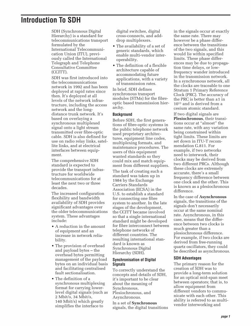
systems (U.S.A. and Japan)and those using the2.048 Mbit/s system.To recover a 64 kbit/schannel from a 140 Mbit/sPDH signal, it’s necessary todemultiplex the signal all theway down to the 2 Mbit/slevel before the location ofthe 64 kbit/s channel can beidentified. PDH requires“steps” (140-34, 34-8, 8-2demultiplex; 2-8, 8-34, 34-140multiplex) to drop out or addan individual speech or datachannel (see Figure 1). This isdue to the bit-stuffing used ateach level.
Limitations of PDH NetworkThe main limitations of PDHare:• Inability to identify indi-
vidual channels in a higher-order bit stream.
• Insufficient capacity fornetwork management;
• Most PDH network manage-ment is proprietary.
• There’s no standardiseddefinition of PDH bit ratesgreater than 140 Mbit/s.
• There are different hierar-chies in use around theworld. Specialized inter-face equipment is requiredto interwork the two hierar-chies.
Basic SDH SignalThe basic format of an SDHsignal allows it to carry manydifferent services in itsVirtual Container (VC)because it is bandwidth-flex-ible. This capability allowsfor such things as the trans-mission of high-speed packet-switched services, ATM,contribution video, and distri-bution video. However, SDH
page 2
Figure 1. PDH multiplexing by steps, showing add/drop function.
140-34 DEMUX
34-8 DEMUX
34-140 MUX
8-34 MUX
2-8 MUX
140 Mbit/s 140 Mbit/s
8 Mbit/s
2 Mbit/s
34 Mbit/s
Drop & Add
8 Mbit/s
34 Mbit/s
8-2 DEMUX
still permits transport andnetworking at the 2 Mbit/s,34 Mbit/s, and 140 Mbit/slevels, accommodating theexisting digital hierarchysignals. In addition, SDHsupports the transport ofsignals based on the1.5 Mbit/s hierarchy.
Transmission HierarchiesFollowing ANSI’s develop-ment of the SONET standard,the ITU-T undertook to definea standard that would addressinterworking between the2048 kbit/s and 1554 kbit/stransmission hierarchies.That effort culminated in
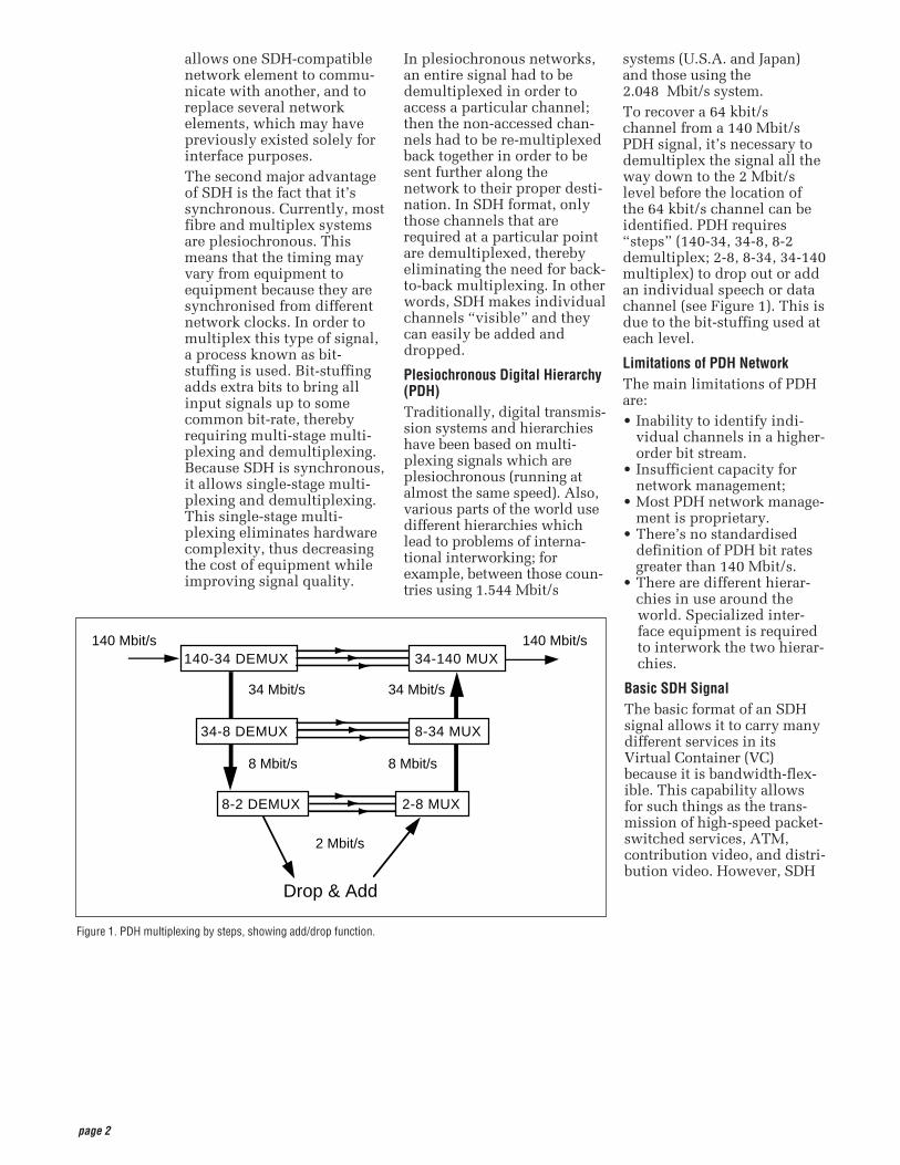
1989 with ITU-T’s publica-tion of the SynchronousDigital Hierarchy (SDH) stan-dards. Tables 1 and 2 compare theNon-synchronous andSynchronous transmissionhierarchies.
page 3
Table 1. Non-Synchronous, PDH HierarchySignal Digital Bit Rate Channels
E0 64 kbit/s One 64 kbit/s
E1 2.048 Mbit/s 32 E0
E2 8.448 Mbit/s 128 E0
E3 34.368 Mbit/s 16 E1
E4 139.264 Mbit/s 64 E1
Table 2. SDH HierarchyBit Rate Abbreviated SDH SDH Capacity
51.84 Mbit/s 51 Mbit/s STM-0 21 E1
155.52 Mbit/s 155 Mbit/s STM-1 63 E1 or 1 E4
622.08 Mbit/s 622 Mbit/s STM-4 252 E1 or 4 E4
2488.32 Mbit/s 2.4 Gbit/s STM-16 1008 E1 or 16 E4
9953.28 Mbit/s 10 Gbit/s STM-64 4032 E1 or 64 E4
39813.12 Mbit/s 40 Gbit/s STM-256 16128 E1 or 256 E4
STM = Synchronous Transport Module
page 4
Synchronous versusAsynchronous Traditionally, transmissionsystems have been asyn-chronous, with each terminalin the network running on itsown recovered clock timing.In digital transmission,“timing” is one of the mostfundamental operations.Since these clocks are notsynchronised, large variationscan occur in the clock rateand thus the signal bit rate.For example, an E3 signalspecified at 34 Mbit/s±20 ppm (parts per million)can produce a timing differ-ence of up to 1789 bit/sbetween one incoming E3signal and another.Asynchronous multiplexinguses multiple stages. Signalssuch as asynchronous E1s(2 Mbit/s) are multiplexed(bit-interleaving), extra bitsare added (bit-stuffing) toaccount for the timing varia-tions of each individualstream and are combined withother bits (framing bits) toform an E2 (8 Mbit/s) stream.Bit-interleaving and bit-stuffing is used again to multi-plex up to E3 (34 Mbit/s). TheE1s are neither visible noraccessible within an E3 frame.E3s are multiplexed up tohigher rates in the samemanner. At the higher asyn-chronous rate, they cannot beaccessed without demulti-plexing.In a synchronous system,such as SDH, the averagefrequency of all clocks in thesystem is the same. Everyslave clock can be traced backto a highly stable referenceclock. Thus, the STM-1 rateremains at a nominal155.52 Mbit/s, allowing manysynchronous STM-1 signalsto be multiplexed withoutany bit-stuffing. Thus, theSTM-1s are easily accessed ata higher STM-N rate.
Low-speed synchronousvirtual container (VC) signalsare also simple to interleaveand transport at higher rates.At low speeds, 2.048 Mbit/sE1 signals are transportedwithin synchronous VC-12signals which run at aconstant rate of 2.304 Mbit/s.Single-step multiplexing upto STM-1 requires no bit-stuffing and VCs are easilyaccessed.A mechanism known as“pointers,” operating inconjunction with buffers,accommodates differences inthe reference source frequen-cies and phase wander, andso prevents data loss duringsynchronisation failures. Thisis discussed in more detaillater in this primer.
Synchronisation Hierarchy Digital switches and digitalcross-connect systems arecommonly employed in thedigital network synchronisa-tion hierarchy. The networkis organized with a master-slave relationship with clocksof the higher-level nodesfeeding timing signals toclocks of the lower-levelnodes. All nodes can betraced up to a PrimaryReference Clock (PRC).
Synchronising SDH The internal clock of an SDHterminal may derive itstiming signal from aSynchronisation Supply Unit(SSU) used by switchingsystems and other equipment.Thus, this terminal can serveas a master for other SDHnodes, providing timing onits outgoing STM-N signal.Other SDH nodes will operatein a slave mode with theirinternal clocks timed by theincoming STM-N signal.Present standards specify thatan SDH network must ulti-mately be able to derive itstiming from a PRC.
Evolution of Timing andSynchronisationThis is a time of great changefor Timing andSynchronisation in thenetwork and there are manychallenges for operators andsuppliers – and many issuesto resolve:• Synchronisation networks
are changing with the intro-duction of SDH; the histor-ical PDH-based syncnetwork will be replaced byan SDH-based architecture.
• New equipment, networktiming, and sync standardshave been developed(Tektronix is contributingexpertise at ITU and ETSI).
• Transport networks areevolving and hybridSDH/PDH has specificproblems due to the quanti-sation of network phasevariation as pointer justifi-cations.
• New services such as videoand ATM depend on excel-lent timing and networksync to deliver goodQuality of Service.
• Jitter/Wander measurementtechnology is changingfrom analogue to digital,leading to dramatically newinstrument capabilities.
• New test equipment stan-dards are being developed(Tektronix is taking aleading role at ITU).
These and many other timingand sync issues are addressedin another publication fromTektronix: PerformanceAssessment of Timing andSynchronisation inBroadband Networks. Copies can be requested fromTektronix offices around theworld, or by e-mail at:[email protected].
Introduction to Synchronisation
page 5
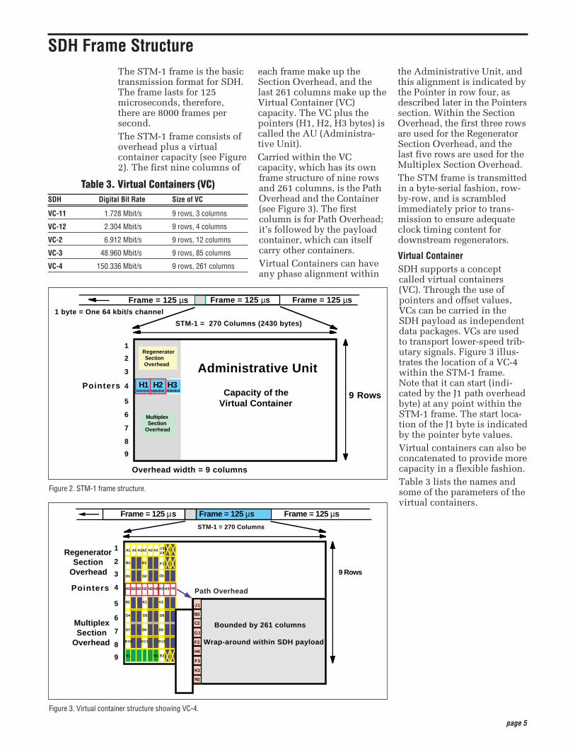
The STM-1 frame is the basictransmission format for SDH.The frame lasts for 125microseconds, therefore,there are 8000 frames persecond. The STM-1 frame consists ofoverhead plus a virtualcontainer capacity (see Figure2). The first nine columns of
each frame make up theSection Overhead, and thelast 261 columns make up theVirtual Container (VC)capacity. The VC plus thepointers (H1, H2, H3 bytes) iscalled the AU (Administra-tive Unit).Carried within the VCcapacity, which has its ownframe structure of nine rowsand 261 columns, is the PathOverhead and the Container(see Figure 3). The firstcolumn is for Path Overhead;it’s followed by the payloadcontainer, which can itselfcarry other containers.Virtual Containers can haveany phase alignment within
the Administrative Unit, andthis alignment is indicated bythe Pointer in row four, asdescribed later in the Pointerssection. Within the SectionOverhead, the first three rowsare used for the RegeneratorSection Overhead, and thelast five rows are used for theMultiplex Section Overhead.The STM frame is transmittedin a byte-serial fashion, row-by-row, and is scrambledimmediately prior to trans-mission to ensure adequateclock timing content fordownstream regenerators.
Virtual ContainerSDH supports a conceptcalled virtual containers(VC). Through the use ofpointers and offset values,VCs can be carried in theSDH payload as independentdata packages. VCs are usedto transport lower-speed trib-utary signals. Figure 3 illus-trates the location of a VC-4within the STM-1 frame.Note that it can start (indi-cated by the J1 path overheadbyte) at any point within theSTM-1 frame. The start loca-tion of the J1 byte is indicatedby the pointer byte values.Virtual containers can also beconcatenated to provide morecapacity in a flexible fashion.Table 3 lists the names andsome of the parameters of thevirtual containers.
Figure 2. STM-1 frame structure.
9 Rows
Administrative Unit
Capacity of the Virtual Container
1
2
3
4
5
6
7
8
9
RegeneratorSectionOverhead
MultiplexSection
Overhead
H3H1 H2Pointers
STM-1 = 270 Columns (2430 bytes)
1 byte = One 64 kbit/s channel
H1H1H1 H2H2H2 H3H3H3
Frame = 125 µs Frame = 125 µsFrame = 125 µs
Overhead width = 9 columns
Figure 3. Virtual container structure showing VC-4.
9 Rows
STM-1 = 270 Columns
RegeneratorSection
Overhead
MultiplexSection
Overhead
1
2
3
4
5
6
7
8
9
Pointers
B2
D4
D7
K2
A1
B1
D1
H1
A1
B2
A1
B2
A2
E1
D2
H2
A2
H2
A2
H2
J 0 /Z0
F1
D3
H3 H3
D10
D5 D6
D8 D9
D11 D12
S1 M1 E2
Frame = 125 µsFrame = 125 µs Frame = 125 µs
Bounded by 261 columns
Wrap-around within SDH payload
B3
C2
G1
F2
H4
F3
K3
N1
J1K1
Path OverheadH3
SDH Frame Structure
Table 3. Virtual Containers (VC)SDH Digital Bit Rate Size of VC
VC-11 1.728 Mbit/s 9 rows, 3 columns
VC-12 2.304 Mbit/s 9 rows, 4 columns
VC-2 6.912 Mbit/s 9 rows, 12 columns
VC-3 48.960 Mbit/s 9 rows, 85 columns
VC-4 150.336 Mbit/s 9 rows, 261 columns
page 6
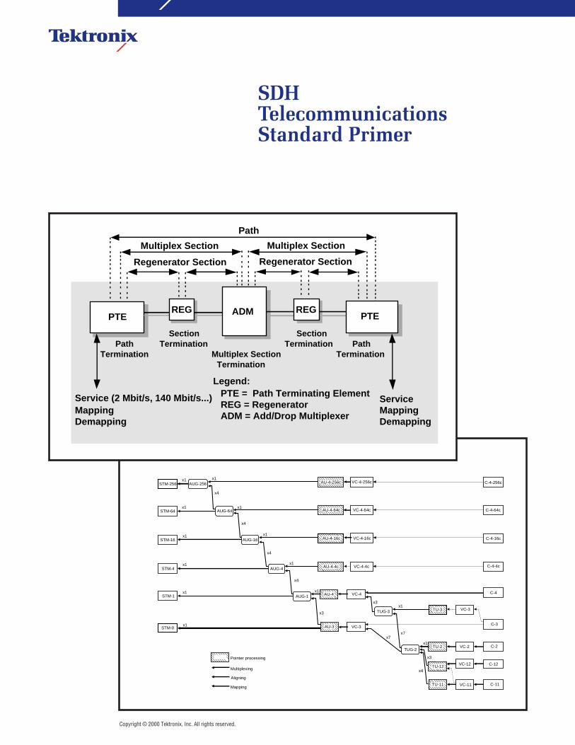
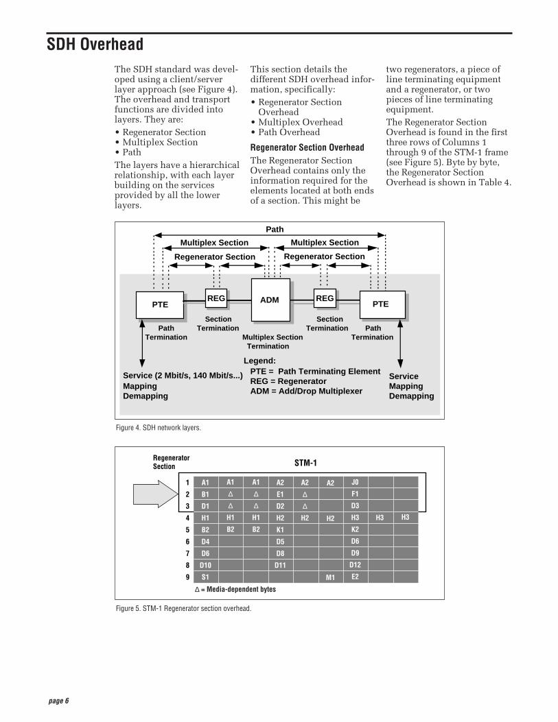
The SDH standard was devel-oped using a client/serverlayer approach (see Figure 4).The overhead and transportfunctions are divided intolayers. They are: • Regenerator Section• Multiplex Section• PathThe layers have a hierarchicalrelationship, with each layerbuilding on the servicesprovided by all the lowerlayers.
This section details thedifferent SDH overhead infor-mation, specifically:• Regenerator Section
Overhead• Multiplex Overhead• Path Overhead
Regenerator Section OverheadThe Regenerator SectionOverhead contains only theinformation required for theelements located at both endsof a section. This might be
two regenerators, a piece ofline terminating equipmentand a regenerator, or twopieces of line terminatingequipment.The Regenerator SectionOverhead is found in the firstthree rows of Columns 1through 9 of the STM-1 frame(see Figure 5). Byte by byte,the Regenerator SectionOverhead is shown in Table 4.
SDH Overhead
Figure 4. SDH network layers.
PathTermination
SectionTermination
Multiplex SectionTermination
PathTermination
SectionTermination
Service (2 Mbit/s, 140 Mbit/s...)MappingDemapping
PTE
Path
Multiplex Section
Regenerator Section Regenerator Section
Multiplex Section
REG
ServiceMappingDemapping
Legend:PTE = Path Terminating ElementREG = RegeneratorADM = Add/Drop Multiplexer
REGPTEADM
Figure 5. STM-1 Regenerator section overhead.
STM-1
1
2
3
4
5
6
7
8
9
A1
B1
D1
H1
B2
D4
D6
D10
S1
A1
∆
∆
H1
B2
A1
∆
∆
H1
B2
A2
E1
D2
H2
K1
D5
D8
D11
A2
∆
∆
H2
A2
H2
M1
J0
F1
D3
H3
K2
D6
D9
D12
E2
H3 H3
Regenerator Section
∆ = Media-dependent bytes

page 7
Multiplex Section OverheadThe Multiplex SectionOverhead contains the infor-mation required between themultiplex section terminationequipment at each end of the
Multiplex section (that is,between consecutive networkelements excluding the regen-erators). The Multiplex SectionOverhead is found in Rows 5
to 9 of Columns 1 through 9of the STM-1 frame (seeFigure 6). Byte by byte, theMultiplex Section Overheadis shown in Table 5.
Figure 6. STM-1 Multiplex section overhead.
STM-1
Multiplex Section
1
2
3
4
5
6
7
8
9
A1
B1
D1
H1
B2
D4
D6
D10
S1
A1
∆
∆
H1
B2
A1
H1
B2
A2
E1
D2
H2
K1
D5
D8
D11
A2
∆
∆
H2
A2
H2
M1
J0
F1
D3
H3
K2
D6
D9
D12
E2
H3 H3
Table 4. Regenerator Section OverheadByte Description
A1 and A2 Framing bytes – These two bytes indicate the beginning of the STM-N frame. The A1, A2 bytes are unscrambled. A1 has the binary value 11110110, and A2 has the binary value 00101000. The frame alignment word of an STM-N frame is composed of (3 x N) A1 bytes followed by (3 x N) A2 bytes.
J0 Regenerator Section (RS) Trace message – It’s used to transmit a Section Access Point Identifier so that a section receiver can verify its continued connection to the intended transmitter. The coding of the J0 byte is the same as for J1 and J2 bytes. This byte is defined only for STM-1 number 1 of an STM-N signal.
Z0 These bytes, which are located at positions S[1,6N+2] to S[1,7N] of an STM-N signal (N > 1), are reserved for future international standardisation.
B1 RS bit interleaved parity code (BIP-8) byte – This is a parity code (even parity), used to check for transmission errors over a regenerator section. Its value is calculated over all bits of the previous STM-N frame after scrambling, then placed in the B1 byte of STM-1 before scrambling. Therefore, this byte is defined only for STM-1 number 1 of an STM-N signal.
E1 RS orderwire byte – This byte is allocated to be used as a local orderwire channel for voice communication between regenerators.
F1 RS user channel byte – This byte is set aside for the user’s purposes; it can be read and/or written to at each section terminating equipment in that line.
D1, D2, D3 RS Data Communications Channel (DCC) bytes – These three bytes form a 192 kbit/s message channel providing a message-based channelfor Operations, Administration and Maintenance (OAM) between pieces of section terminating equipment. The channel can be used from a central location for control, monitoring, administration, and other communication needs.

page 8
Table 5. Multiplex Section OverheadByte Description
B2 Multiplex Section (MS) bit interleaved parity code (MS BIP-24) byte – This bit interleaved parity N x 24 code is used to determine if a transmis-sion error has occurred over a multiplex section. It’s even parity, and is calculated overall bits of the MS Overhead and the STM-N frame of theprevious STM-N frame before scrambling. The value is placed in the three B2 bytes of the MS Overhead before scrambling. These bytes areprovided for all STM-1 signals in an STM-N signal.
K1 and K2 Automatic Protection Switching (APS channel) bytes – These two bytes are used for MSP (Multiplex Section Protection) signaling between multi-plex level entities for bi-directional automatic protection switching and for communicating Alarm Indication Signal (AIS) and Remote DefectIndication (RDI) conditions. The Multiplex Section Remote Defect Indication (MS-RDI) is used to return an indication to the transmit end that thereceived end has detected an incoming section defect or is receiving MS-AIS. MS-RDI is generated by inserting a “110” code in positions 6, 7, and8 of the K2 byte before scrambling.K1 Byte
Bits 1-4 Type of request1111 Lock out of Protection1110 Forced Switch1101 Signal Fail – High Priority1100 Signal Fail – Low Priority1011 Signal Degrade – High Priority1010 Signal Degrade – Low Priority1001 (not used)1000 Manual Switch0111 (not used)0110 Wait-to-Restore0101 (not used)0100 Exercise0011 (not used)0010 Reverse Request0001 Do Not Revert0000 No Request
Bits 5-8 Indicate the number of the channel requested
K2 Byte Bits 1-4 Selects channel numberBit 5 Indication of architecture
0 1+11 1:n
Bits 6-8 Indicate mode of operation111 MS-AIS110 MS-RDI101 Provisioned mode is bi-directional100 Provisioned mode is unidirectional011 Future use010 Future use001 Future use000 Future use
D4 to D12 MS Data Communications Channel (DCC) bytes – These nine bytes form a 576 kbit/s message channel from a central location for OAM informa-tion (control, maintenance, remote provisioning, monitoring, administration and other communication needs).
S1 Synchronisation status message byte (SSMB) – Bits 5 to 8 of this S1 byte are used to carry the synchronisation messages. Following is theassignment of bit patterns to the four synchronisation levels agreed to within ITU-T (other values are reserved):Bits 5-8
0000 Quality unknown (existing sync. network)0010 G.811 PRC0100 SSU-A (G.812 transit)1000 SSU-B (G.812 local)1011 G.813 Option 1 Synchronous Equipment Timing Clock (SEC)1111 Do not use for synchronisation. This message may be emulated by equipment failures and will be emulated by a Multiplex Section
AIS signal.
M1 MS remote error indication – The M1 byte of an STM-1 or the first STM-1 of an STM-N is used for a MS layer remote error indication (MS-REI).Bits 2 to 8 of the M1 byte are used to carry the error count of the interleaved bit blocks that the MS BIP-24xN has detected to be in error at the farend of the section. This value is truncated at 255 for STM-N >4.
E2 MS orderwire byte – This orderwire byte provides a 64 kbit/s channel between multiplex entities for an express orderwire. It’s a voice channel foruse by craftspersons and can be accessed at multiplex section terminations.
page 9
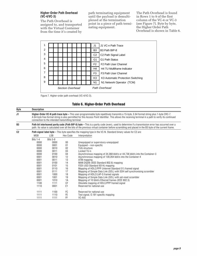
Higher-Order Path Overhead(VC-4/VC-3)The Path Overhead isassigned to, and transportedwith the Virtual Containerfrom the time it’s created by
path terminating equipmentuntil the payload is demulti-plexed at the terminationpoint in a piece of path termi-nating equipment.
The Path Overhead is foundin Rows 1 to 9 of the firstcolumn of the VC-4 or VC-3(see Figure 7). Byte by byte,the Higher Order PathOverhead is shown in Table 6.
Table 6. Higher-Order Path OverheadByte Description
J1 Higher-Order VC-N path trace byte – This user-programmable byte repetitively transmits a 15-byte, E.64 format string plus 1-byte CRC-7. A 64-byte free-format string is also permitted for this Access Point Identifier. This allows the receiving terminal in a path to verify its continuedconnection to the intended transmitting terminal.
B3 Path bit interleaved parity code (Path BIP-8) byte – This is a parity code (even), used to determine if a transmission error has occurred over apath. Its value is calculated over all the bits of the previous virtual container before scrambling and placed in the B3 byte of the current frame.
C2 Path signal label byte – This byte specifies the mapping type in the VC-N. Standard binary values for C2 are:MSB LSB Hex Code Interpretation
Bits 1-4 Bits 5-80000 0000 00 Unequipped or supervisory-unequipped0000 0001 01 Equipped – non-specific 0000 0010 02 TUG structure0000 0011 03 Locked TU-n 0000 0100 04 Asynchronous mapping of 34,368 kbit/s or 44,736 kbit/s into the Container-30001 0010 12 Asynchronous mapping of 139,264 kbit/s into the Container-40001 0011 13 ATM mapping0001 0100 14 MAN DQDB (IEEE Standard 802.6) mapping0001 0101 15 FDDI (ISO Standard 9314) mapping0001 0110 16 Mapping of HDLC/PPP (Internet Standard 51) framed signal0001 0111 17 Mapping of Simple Data Link (SDL) with SDH self synchronising scrambler 0001 1000 18 Mapping of HDLC/LAP-S framed signals0001 1001 19 Mapping of Simple Data Link (SDL) with set-reset scrambler 0001 1010 1A Mapping of 10 Gbit/s Ethernet frames (IEEE 802.3)1100 1111 CF Obsolete mapping of HDLC/PPP framed signal1110 0001 E1 Reserved for national use
: : : :1111 1100 FC Reserved for national use1111 1110 FE Test signal, O.181 specific mapping 1111 1111 FF VC-AIS
Figure 7. Higher-order path overhead (VC-4/VC-3).
J1 J1 VC-n Path Trace
B3 B3 Path BIP-8
C2 C2 Path Signal Label
G1 G1 Path Status
F2 F2 Path User Channel
H4 H4 TU Multiframe Indicator
F3 F3 Path User Channel
K3 K3 Automatic Protection Switching
N1 N1 Network Operator (TCM)
1
2
3
4
5
6
7
8
9
Path OverheadSection Overhead

page 10
Byte Description
G1 Path status byte – This byte is used to convey the path terminating status and performance back to the originating path terminating equipment.Therefore the bi-directional path in its entirety can be monitored, from either end of the path.
Byte G1 is allocated to convey back to a VC-4-Xc/VC-4/VC-3 trail termination source the status and performance of the complete trail. Bits 5 to 7may be used to provide an enhanced remote defect indication with additional differentiation between the payload defect (PLM), server defects (AIS,LOP) and connectivity defects (TIM, UNEQ). The following codes are used:Bits 5-7 Meaning Triggers
001 No remote defect No remote defect010 E-RDI Payload defect PLM101 E-RDI Server defect AIS, LOP110 E-RDI Connectivity defect TIM, UNEQ
The E-RDI G1 (bits 5-7) code interpretation provides for interworking with equipment which supports RDI. It is not necessary for the interpretationto identify if the equipment supports RDI or E-RDI. For the E-RDI codes, bit 7 is set to the inverse of bit 6. Following is the E-RDI G1 (bits 5-7) codeinterpretation:Bits 5-7 E-RDI Interpretation
000 No remote defect (Note 1)001 No remote defect010 E-RDI Payload defect (Note 2)011 No remote defect (Note 1)100 E-RDI Server defect (Note 1)101 Remote E-RDI Server defect110 Remote E-RDI Connectivity defect111 Remote E-RDI Server Defect (Note 1)
NOTE 1: These codes are generated by RDI supporting equipment and are interpreted by E-RDI supporting equipment as shown. For equipmentsupporting RDI, clause 9.3.1.4/G.707, this code is triggered by the presence or absence of one of the following defects: AIS, LOP, TIM, or UNEQ.Equipment conforming to an earlier version of this standard may include PLM as a trigger condition. ATM equipment complying with the 1993version of ITU-T Recommendation I.432 may include LCD as a trigger condition. Note that for some national networks, this code was triggeredonly by an AIS or LOP defect.NOTE 2: ATM equipment complying with the 08/96 version of ITU-T Recommendation I.432.2 may include LCD as a trigger condition.
F2 Path user channel byte – This byte is used for user communication between path elements.
H4 Position and Sequence Indicator byte – This byte provides a multi frame and sequence indicator for virtual VC-3/4 concatenation and a generalizedposition indicator for payloads. In the latter case, the content is payload specific (e.g., H4 can be used as a multiframe indicator for VC-2/1payload). For mapping of DQDB in VC-4, the H4 byte carries the slot boundary information and the Link Status Signal (LSS). Bits 1-2 are used forthe LSS code as described in IEEE Standard 802.6. Bits 3-8 form the slot offset indicator. The slot offset indicator contains a binary number indi-cating the offset in octets between the H4 octet and the first slot boundary following the H4 octet. The valid range of the slot offset indicator value is0 to 52. A received value of 53 to 63 corresponds to an error condition.
F3 Path user channel byte – This byte is allocated for communication purposes between path elements and is payload dependent.
K3 APS signalling is provided in K3 bits 1-4, allocated for protection at the VC-4/3 path levels. K3 bits 5-8 are allocated for future use. These bits haveno defined value. The receiver is required to ignore their content.
1 2 3 4 5 6 7 8
REI RDI Reserved Spare
Table 6 (contd)
page 11
Byte Description
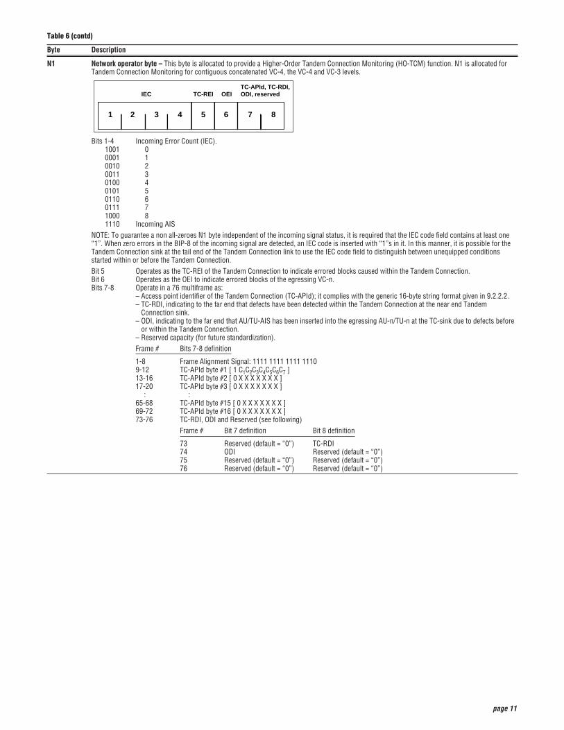
N1 Network operator byte – This byte is allocated to provide a Higher-Order Tandem Connection Monitoring (HO-TCM) function. N1 is allocated forTandem Connection Monitoring for contiguous concatenated VC-4, the VC-4 and VC-3 levels.
Bits 1-4 Incoming Error Count (IEC).1001 00001 1 0010 20011 30100 40101 50110 60111 71000 81110 Incoming AIS
NOTE: To guarantee a non all-zeroes N1 byte independent of the incoming signal status, it is required that the IEC code field contains at least one“1”. When zero errors in the BIP-8 of the incoming signal are detected, an IEC code is inserted with “1”s in it. In this manner, it is possible for theTandem Connection sink at the tail end of the Tandem Connection link to use the IEC code field to distinguish between unequipped conditionsstarted within or before the Tandem Connection.Bit 5 Operates as the TC-REI of the Tandem Connection to indicate errored blocks caused within the Tandem Connection.Bit 6 Operates as the OEI to indicate errored blocks of the egressing VC-n.Bits 7-8 Operate in a 76 multiframe as:
– Access point identifier of the Tandem Connection (TC-APId); it complies with the generic 16-byte string format given in 9.2.2.2.– TC-RDI, indicating to the far end that defects have been detected within the Tandem Connection at the near end Tandem
Connection sink.– ODI, indicating to the far end that AU/TU-AIS has been inserted into the egressing AU-n/TU-n at the TC-sink due to defects before
or within the Tandem Connection.– Reserved capacity (for future standardization).Frame # Bits 7-8 definition
1-8 Frame Alignment Signal: 1111 1111 1111 11109-12 TC-APId byte #1 [ 1 C1C2C3C4C5C6C7 ]13-16 TC-APId byte #2 [ 0 X X X X X X X ]17-20 TC-APId byte #3 [ 0 X X X X X X X ]
: :65-68 TC-APId byte #15 [ 0 X X X X X X X ]69-72 TC-APId byte #16 [ 0 X X X X X X X ]73-76 TC-RDI, ODI and Reserved (see following)
Frame # Bit 7 definition Bit 8 definition
73 Reserved (default = “0”) TC-RDI74 ODI Reserved (default = “0”)75 Reserved (default = “0”) Reserved (default = “0”)76 Reserved (default = “0”) Reserved (default = “0”)
1 2 3 4 5 6 7 8
IEC TC-REI OEITC-APId, TC-RDI,ODI, reserved
Table 6 (contd)
page 12
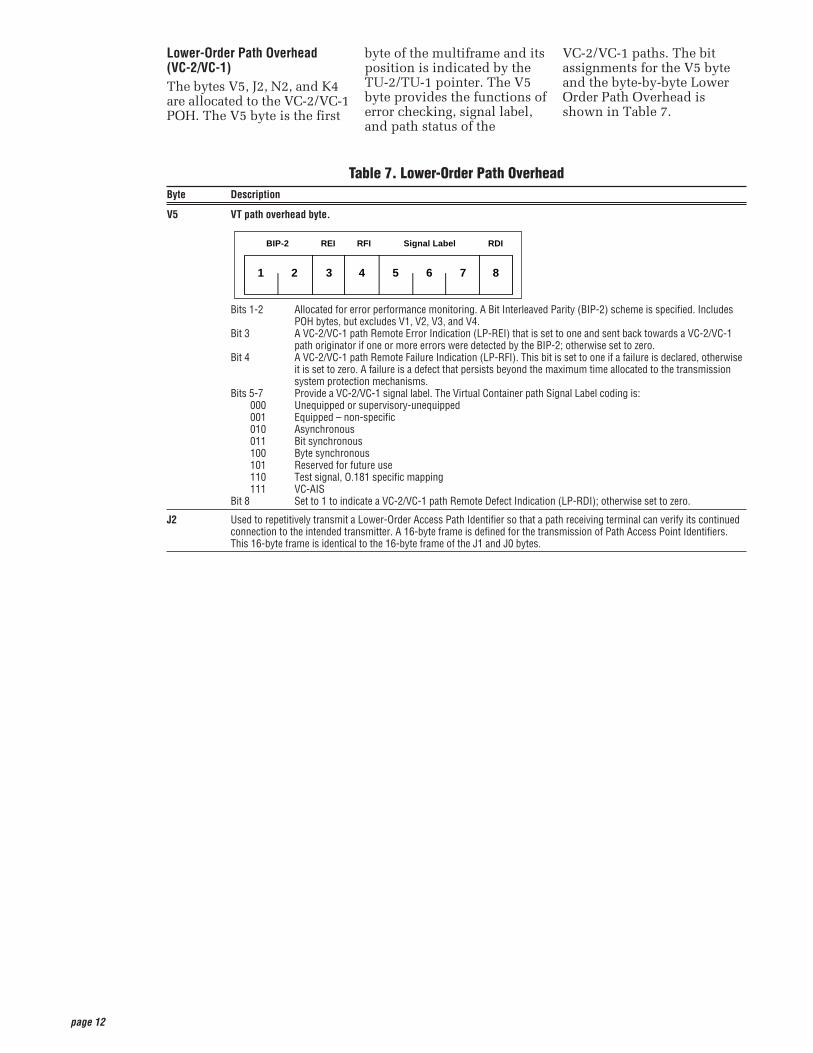
Lower-Order Path Overhead(VC-2/VC-1)The bytes V5, J2, N2, and K4are allocated to the VC-2/VC-1POH. The V5 byte is the first
byte of the multiframe and itsposition is indicated by theTU-2/TU-1 pointer. The V5byte provides the functions oferror checking, signal label,and path status of the
VC-2/VC-1 paths. The bitassignments for the V5 byteand the byte-by-byte LowerOrder Path Overhead isshown in Table 7.
Table 7. Lower-Order Path OverheadByte Description
V5 VT path overhead byte.
Bits 1-2 Allocated for error performance monitoring. A Bit Interleaved Parity (BIP-2) scheme is specified. IncludesPOH bytes, but excludes V1, V2, V3, and V4.
Bit 3 A VC-2/VC-1 path Remote Error Indication (LP-REI) that is set to one and sent back towards a VC-2/VC-1path originator if one or more errors were detected by the BIP-2; otherwise set to zero.
Bit 4 A VC-2/VC-1 path Remote Failure Indication (LP-RFI). This bit is set to one if a failure is declared, otherwiseit is set to zero. A failure is a defect that persists beyond the maximum time allocated to the transmissionsystem protection mechanisms.
Bits 5-7 Provide a VC-2/VC-1 signal label. The Virtual Container path Signal Label coding is:000 Unequipped or supervisory-unequipped001 Equipped – non-specific 010 Asynchronous011 Bit synchronous100 Byte synchronous101 Reserved for future use110 Test signal, O.181 specific mapping111 VC-AIS
Bit 8 Set to 1 to indicate a VC-2/VC-1 path Remote Defect Indication (LP-RDI); otherwise set to zero.
J2 Used to repetitively transmit a Lower-Order Access Path Identifier so that a path receiving terminal can verify its continuedconnection to the intended transmitter. A 16-byte frame is defined for the transmission of Path Access Point Identifiers.This 16-byte frame is identical to the 16-byte frame of the J1 and J0 bytes.
1 2 3 4 5 6 7 8
BIP-2 REI RFI Signal Label RDI
page 13
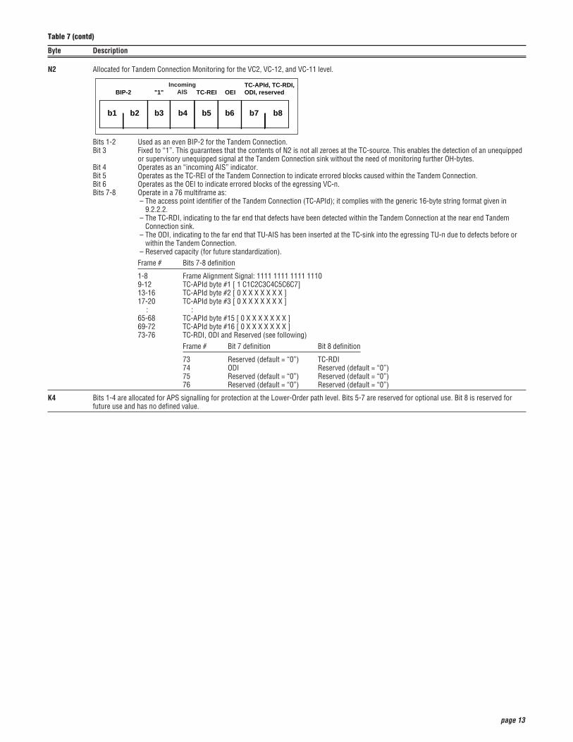
N2 Allocated for Tandem Connection Monitoring for the VC2, VC-12, and VC-11 level.
Bits 1-2 Used as an even BIP-2 for the Tandem Connection.Bit 3 Fixed to “1”. This guarantees that the contents of N2 is not all zeroes at the TC-source. This enables the detection of an unequipped
or supervisory unequipped signal at the Tandem Connection sink without the need of monitoring further OH-bytes.Bit 4 Operates as an “incoming AIS” indicator.Bit 5 Operates as the TC-REI of the Tandem Connection to indicate errored blocks caused within the Tandem Connection.Bit 6 Operates as the OEI to indicate errored blocks of the egressing VC-n.Bits 7-8 Operate in a 76 multiframe as:
– The access point identifier of the Tandem Connection (TC-APId); it complies with the generic 16-byte string format given in9.2.2.2.
– The TC-RDI, indicating to the far end that defects have been detected within the Tandem Connection at the near end TandemConnection sink.
– The ODI, indicating to the far end that TU-AIS has been inserted at the TC-sink into the egressing TU-n due to defects before orwithin the Tandem Connection.
– Reserved capacity (for future standardization).Frame # Bits 7-8 definition
1-8 Frame Alignment Signal: 1111 1111 1111 11109-12 TC-APId byte #1 [ 1 C1C2C3C4C5C6C7]13-16 TC-APId byte #2 [ 0 X X X X X X X ]17-20 TC-APId byte #3 [ 0 X X X X X X X ]
: :65-68 TC-APId byte #15 [ 0 X X X X X X X ]69-72 TC-APId byte #16 [ 0 X X X X X X X ]73-76 TC-RDI, ODI and Reserved (see following)
Frame # Bit 7 definition Bit 8 definition
73 Reserved (default = “0”) TC-RDI74 ODI Reserved (default = “0”)75 Reserved (default = “0”) Reserved (default = “0”)76 Reserved (default = “0”) Reserved (default = “0”)
K4 Bits 1-4 are allocated for APS signalling for protection at the Lower-Order path level. Bits 5-7 are reserved for optional use. Bit 8 is reserved forfuture use and has no defined value.
b1 b2 b3 b4 b5 b6 b7 b8
BIP-2 "1" TC-REI OEITC-APId, TC-RDI,ODI, reserved
IncomingAIS
Table 7 (contd)
Byte Description

page 14
page 15
The SDH frame structure hasbeen designed to contain alarge amount of overheadinformation. The overheadinformation provides for avariety of management andother functions such as:• Alarm Indication Signals
(AIS)• Error Performance
Monitoring using BIP-N• Pointer Adjustment
Information• Path Status• Path Trace• Section Trace• Remote Defect, Error, and
Failure Indications• Signal Labels• New Data Flag Indications• Data Communications
Channels (DCC)• Automatic Protection
Switching (APS) Control• Orderwire• Synchronisation Status
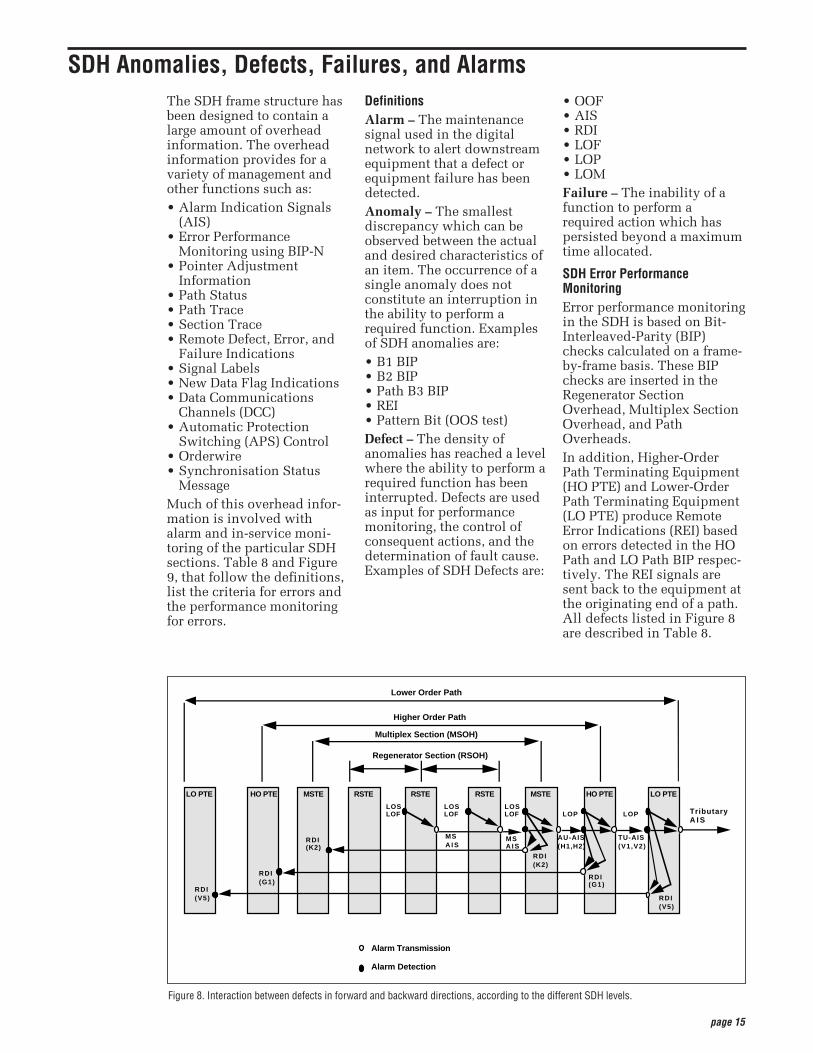
MessageMuch of this overhead infor-mation is involved withalarm and in-service moni-toring of the particular SDHsections. Table 8 and Figure9, that follow the definitions,list the criteria for errors andthe performance monitoringfor errors.
DefinitionsAlarm – The maintenancesignal used in the digitalnetwork to alert downstreamequipment that a defect orequipment failure has beendetected. Anomaly – The smallestdiscrepancy which can beobserved between the actualand desired characteristics ofan item. The occurrence of asingle anomaly does notconstitute an interruption inthe ability to perform arequired function. Examplesof SDH anomalies are: • B1 BIP• B2 BIP• Path B3 BIP• REI• Pattern Bit (OOS test)Defect – The density ofanomalies has reached a levelwhere the ability to perform arequired function has beeninterrupted. Defects are usedas input for performancemonitoring, the control ofconsequent actions, and thedetermination of fault cause.Examples of SDH Defects are:
• OOF• AIS• RDI• LOF• LOP• LOMFailure – The inability of afunction to perform arequired action which haspersisted beyond a maximumtime allocated.
SDH Error PerformanceMonitoringError performance monitoringin the SDH is based on Bit-Interleaved-Parity (BIP)checks calculated on a frame-by-frame basis. These BIPchecks are inserted in theRegenerator SectionOverhead, Multiplex SectionOverhead, and PathOverheads.In addition, Higher-OrderPath Terminating Equipment(HO PTE) and Lower-OrderPath Terminating Equipment(LO PTE) produce RemoteError Indications (REI) basedon errors detected in the HOPath and LO Path BIP respec-tively. The REI signals aresent back to the equipment atthe originating end of a path.All defects listed in Figure 8are described in Table 8.
Figure 8. Interaction between defects in forward and backward directions, according to the different SDH levels.
MSTE RSTEHO PTELO PTE RSTE RSTE MSTE HO PTE LO PTE
Regenerator Section (RSOH)
Multiplex Section (MSOH)
Higher Order Path
Lower Order Path
Alarm Transmission
Alarm Detection
RDI(V5)
RDI(G1)
RDI(K2)
RDI(K2)
RDI(G1)
RDI(V5)
MSA I S
LOPLOSLOF
AU-AIS(H1,H2)
LOP
TU-AIS(V1,V2)
MSA I S
LOSLOF
LOSLOF Tributary
A I S
SDH Anomalies, Defects, Failures, and Alarms
page 16
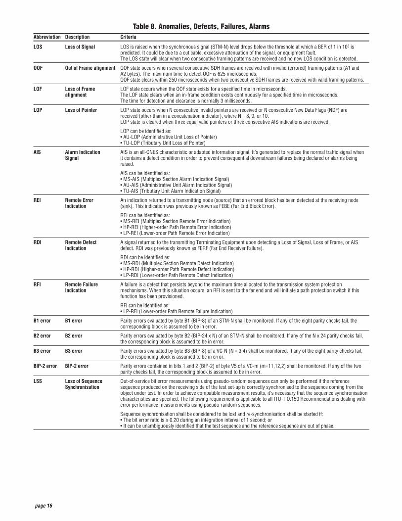
Table 8. Anomalies, Defects, Failures, AlarmsAbbreviation Description Criteria
LOS Loss of Signal LOS is raised when the synchronous signal (STM-N) level drops below the threshold at which a BER of 1 in 103 is predicted. It could be due to a cut cable, excessive attenuation of the signal, or equipment fault.The LOS state will clear when two consecutive framing patterns are received and no new LOS condition is detected.
OOF Out of Frame alignment OOF state occurs when several consecutive SDH frames are received with invalid (errored) framing patterns (A1 and A2 bytes). The maximum time to detect OOF is 625 microseconds.OOF state clears within 250 microseconds when two consecutive SDH frames are received with valid framing patterns.
LOF Loss of Frame LOF state occurs when the OOF state exists for a specified time in microseconds. alignment The LOF state clears when an in-frame condition exists continuously for a specified time in microseconds.
The time for detection and clearance is normally 3 milliseconds.
LOP Loss of Pointer LOP state occurs when N consecutive invalid pointers are received or N consecutive New Data Flags (NDF) are received (other than in a concatenation indicator), where N = 8, 9, or 10.LOP state is cleared when three equal valid pointers or three consecutive AIS indications are received.
LOP can be identified as:• AU-LOP (Administrative Unit Loss of Pointer)• TU-LOP (Tributary Unit Loss of Pointer)
AIS Alarm Indication AIS is an all-ONES characteristic or adapted information signal. It’s generated to replace the normal traffic signal when Signal it contains a defect condition in order to prevent consequential downstream failures being declared or alarms being
raised.
AIS can be identified as:• MS-AIS (Multiplex Section Alarm Indication Signal)• AU-AIS (Administrative Unit Alarm Indication Signal)• TU-AIS (Tributary Unit Alarm Indication Signal)
REI Remote Error An indication returned to a transmitting node (source) that an errored block has been detected at the receiving node Indication (sink). This indication was previously known as FEBE (Far End Block Error).
REI can be identified as:• MS-REI (Multiplex Section Remote Error Indication)• HP-REI (Higher-order Path Remote Error Indication)• LP-REI (Lower-order Path Remote Error Indication)
RDI Remote Defect A signal returned to the transmitting Terminating Equipment upon detecting a Loss of Signal, Loss of Frame, or AIS Indication defect. RDI was previously known as FERF (Far End Receiver Failure).
RDI can be identified as:• MS-RDI (Multiplex Section Remote Defect Indication)• HP-RDI (Higher-order Path Remote Defect Indication)• LP-RDI (Lower-order Path Remote Defect Indication)
RFI Remote Failure A failure is a defect that persists beyond the maximum time allocated to the transmission system protection Indication mechanisms. When this situation occurs, an RFI is sent to the far end and will initiate a path protection switch if this
function has been provisioned.
RFI can be identified as:• LP-RFI (Lower-order Path Remote Failure Indication)
B1 error B1 error Parity errors evaluated by byte B1 (BIP-8) of an STM-N shall be monitored. If any of the eight parity checks fail, the corresponding block is assumed to be in error.
B2 error B2 error Parity errors evaluated by byte B2 (BIP-24 x N) of an STM-N shall be monitored. If any of the N x 24 parity checks fail, the corresponding block is assumed to be in error.
B3 error B3 error Parity errors evaluated by byte B3 (BIP-8) of a VC-N (N = 3,4) shall be monitored. If any of the eight parity checks fail, the corresponding block is assumed to be in error.
BIP-2 error BIP-2 error Parity errors contained in bits 1 and 2 (BIP-2) of byte V5 of a VC-m (m=11,12,2) shall be monitored. If any of the two parity checks fail, the corresponding block is assumed to be in error.
LSS Loss of Sequence Out-of-service bit error measurements using pseudo-random sequences can only be performed if the reference Synchronisation sequence produced on the receiving side of the test set-up is correctly synchronised to the sequence coming from the
object under test. In order to achieve compatible measurement results, it’s necessary that the sequence synchronisation characteristics are specified. The following requirement is applicable to all ITU-T O.150 Recommendations dealing with error performance measurements using pseudo-random sequences.
Sequence synchronisation shall be considered to be lost and re-synchronisation shall be started if:• The bit error ratio is ≥ 0.20 during an integration interval of 1 second; or• It can be unambiguously identified that the test sequence and the reference sequence are out of phase.
page 17
SDH provides payloadpointers to permit differencesin the phase and frequency ofthe Virtual Containers (VC-N)with respect to the STM-Nframe. Lower-order pointersare also provided to permitphase differences betweenVC-1/VC-2 and the higher-order VC-3/VC-4.On a frame-by-frame basis,the payload pointer indicatesthe offset between the VCpayload and the STM-Nframe by identifying the loca-tion of the first byte of the VCin the payload. In otherwords, the VC is allowed to“float” within the STM-1frame capacity.To make this possible, withineach STM-N frame, there’s apointer, known as the VCPayload Pointer, that indi-cates where the actualpayload container starts. Fora VC-4 payload, this pointeris located in columns 1 and 4of the fourth row of theSection Overhead. The bytesH1 and H2 (two 8-bit bytes) ofthe Overhead can be viewedas one value (see Figure 9).The pointer value indicatesthe offset in bytes from thepointer to the first byte of the
VC, which is the J1 byte.Because the SectionOverhead bytes are notcounted, and starting pointsare at 3-byte increments for aVC-4 payload, the possiblerange is:
Total STM-1 bytes – SectionOverhead bytes = Pointer valuerange
For example:
(2430 – 81)/3 = 783 valid pointerpositions
That is, the value of thepointer has a range of 0 to782. For example, if the VC-4Payload Pointer has a value of0, then the VC-4 begins in thebyte adjacent to the H3 byteof the Overhead; if thePayload Pointer has a value of87, then the VC-4 begins inthe byte adjacent to the K2byte of the Overhead in thenext row. The pointer value, which is abinary number, is carried inbits 7 through 16 of the H1-H2 pointer word. The firstfour bits of the VC-4 payloadpointer make provision forindicating a change in the VC,and thus an arbitrary changein the value of the pointer.
These four bits, the N-bits, areknown as the New Data Flag.The VC pointer value thataccompanies the New DataFlag will indicate the newoffset.
Payload PointersWhen there’s a difference inphase or frequency, thepointer value is adjusted. Toaccomplish this, a processknown as byte stuffing isused. In other words, the VCpayload pointer indicateswhere in the containercapacity a VC starts, and thebyte stuffing process allowsdynamic alignment of the VCin case it slips in time.
Positive Pointer JustificationWhen the data rate of the VCis too slow in relation to therate of the STM-1 frame, bits7, 9, 11, 13, and 15 of thepointer word are inverted inone frame, thus allowing 5-bitmajority voting at the receiver(these bits are known as theI-bits or Increment bits).Periodically, when the VC isabout one byte off, these bitsare inverted, indicating thatpositive stuffing must occur. An additional byte is stuffedin, allowing the alignment ofthe container to slip back intime. This is known as posi-tive stuffing, and the stuffbyte is made up of non-infor-mation bits. The actual posi-tive stuff byte immediatelyfollows the H3 byte (that is,the stuff byte is within the VCportion). The pointer is incre-mented by one in the nextframe, and the subsequentpointers contain the newvalue.
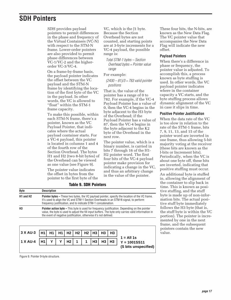
Figure 9. Pointer 9-byte structure.
3 X AU-3 H1 H1 H1 H2 H2 H2 H3 H3 H3
1 X AU-4 H1 Y Y H2 1 1 H3 H3 H31 = All 1s Y = 1001SS11(S bits unspecified)
SDH Pointers
Table 9. SDH PointersByte Description
H1 and H2 Pointer bytes – These two bytes, the VC payload pointer, specify the location of the VC frame.It’s used to align the VC and STM-1 Section Overheads in an STM-N signal, to perform frequency justification, and to indicate STM-1 concatenation.
H3 Pointer action byte – This byte is used for frequency justification. Depending on the pointer value, the byte is used to adjust the fill input buffers. The byte only carries valid information in the event of negative justification, otherwise it’s not defined.
page 18
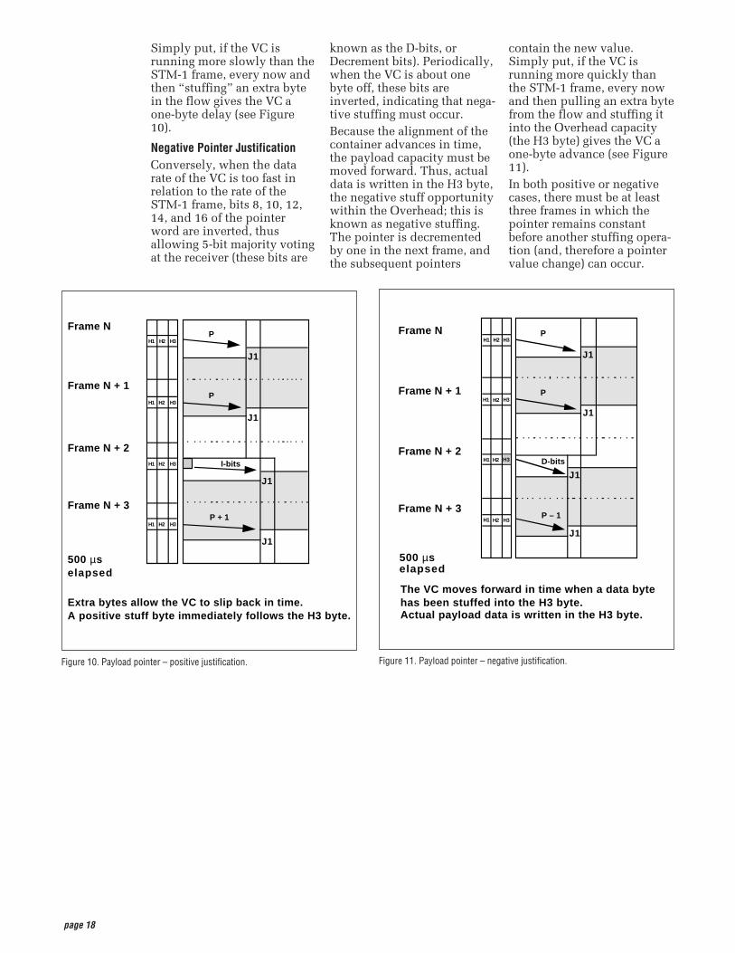
Simply put, if the VC isrunning more slowly than theSTM-1 frame, every now andthen “stuffing” an extra bytein the flow gives the VC aone-byte delay (see Figure10).
Negative Pointer JustificationConversely, when the datarate of the VC is too fast inrelation to the rate of theSTM-1 frame, bits 8, 10, 12,14, and 16 of the pointerword are inverted, thusallowing 5-bit majority votingat the receiver (these bits are
known as the D-bits, orDecrement bits). Periodically,when the VC is about onebyte off, these bits areinverted, indicating that nega-tive stuffing must occur.Because the alignment of thecontainer advances in time,the payload capacity must bemoved forward. Thus, actualdata is written in the H3 byte,the negative stuff opportunitywithin the Overhead; this isknown as negative stuffing.The pointer is decrementedby one in the next frame, andthe subsequent pointers
contain the new value.Simply put, if the VC isrunning more quickly thanthe STM-1 frame, every nowand then pulling an extra bytefrom the flow and stuffing itinto the Overhead capacity(the H3 byte) gives the VC aone-byte advance (see Figure11).In both positive or negativecases, there must be at leastthree frames in which thepointer remains constantbefore another stuffing opera-tion (and, therefore a pointervalue change) can occur.
Figure 10. Payload pointer – positive justification. Figure 11. Payload pointer – negative justification.
H1 H2 H3
H1 H2 H3
H1 H2
H1 H2 H3
Frame N + 1
Frame N
Frame N + 2
Frame N + 3
P
P
P – 1
500 µs elapsed
J1
J1
J1
J1
The VC moves forward in time when a data bytehas been stuffed into the H3 byte.Actual payload data is written in the H3 byte.
H3 D-bits
H1 H2 H3
H1 H2 H3
H1 H2 H3
H1 H2 H3
Frame N + 1
Frame N
Frame N + 2
Frame N + 3
P
P
P + 1
500 µselapsed
J1
J1
J1
J1
Extra bytes allow the VC to slip back in time. A positive stuff byte immediately follows the H3 byte.
I-bits
page 19
The multiplexing principlesof SDH follow, using theseterms and definitions:• Mapping – A process used
when tributaries areadapted into VirtualContainers (VCs) by addingjustification bits and PathOverhead (POH) informa-tion.
• Aligning – This processtakes place when a pointeris included in a TributaryUnit (TU) or anAdministrative Unit (AU),to allow the first byte of theVirtual Container to belocated.
• Multiplexing – This processis used when multiplelower-order path layersignals are adapted into ahigher-order path signal, orwhen the higher-order pathsignals are adapted into aMultiplex Section.
• Stuffing – As the tributarysignals are multiplexed andaligned, some sparecapacity has been designedinto the SDH frame toprovide enough space forall the various tributaryrates. Therefore, at certainpoints in the multiplexinghierarchy, this spacecapacity is filled with“fixed stuffing” bits thatcarry no information, butare required to fill up theparticular frame.
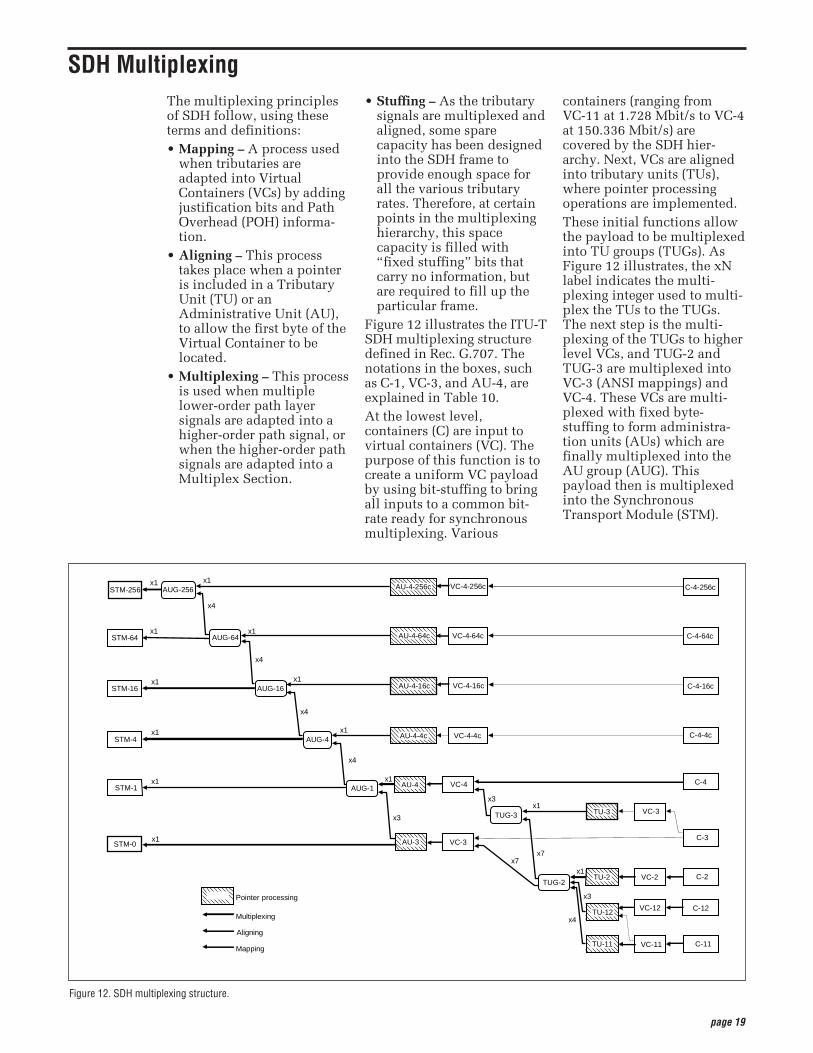
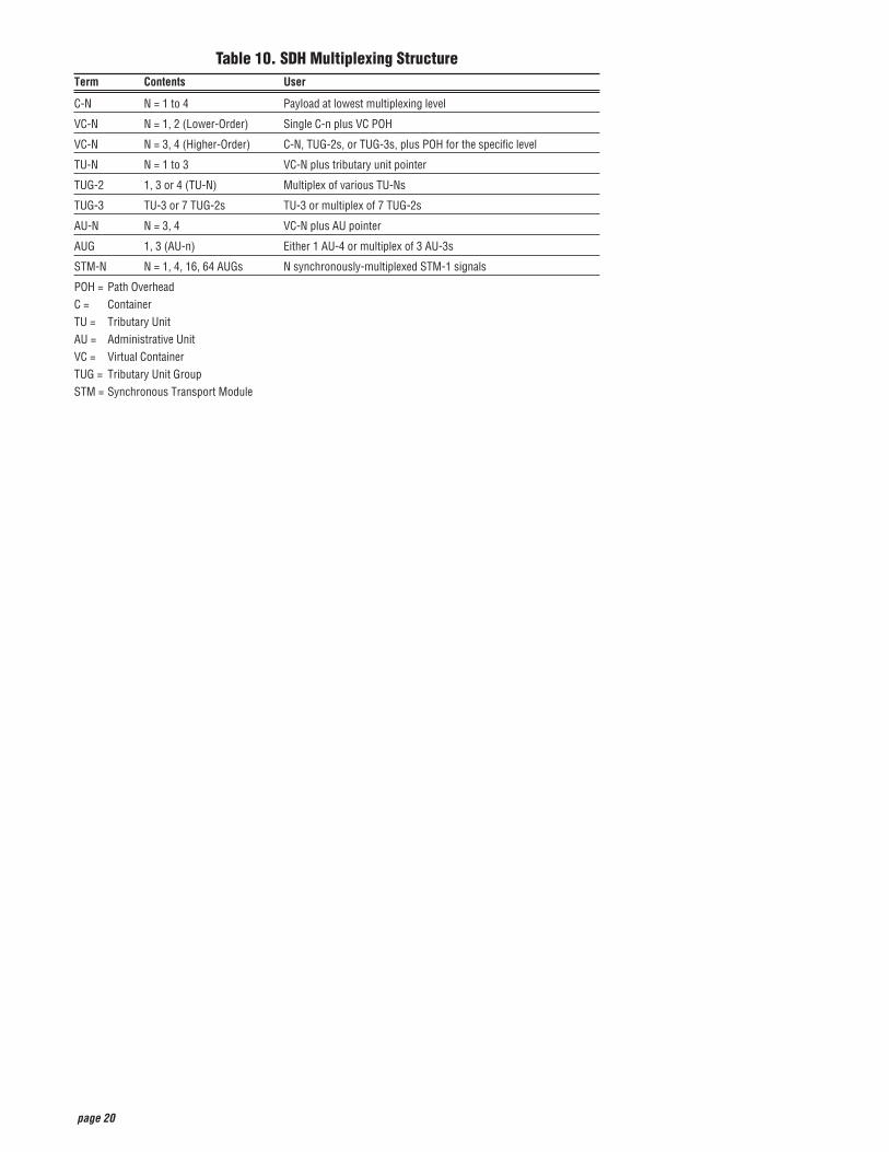
Figure 12 illustrates the ITU-TSDH multiplexing structuredefined in Rec. G.707. Thenotations in the boxes, suchas C-1, VC-3, and AU-4, areexplained in Table 10.At the lowest level,containers (C) are input tovirtual containers (VC). Thepurpose of this function is tocreate a uniform VC payloadby using bit-stuffing to bringall inputs to a common bit-rate ready for synchronousmultiplexing. Various
containers (ranging fromVC-11 at 1.728 Mbit/s to VC-4at 150.336 Mbit/s) arecovered by the SDH hier-archy. Next, VCs are alignedinto tributary units (TUs),where pointer processingoperations are implemented.These initial functions allowthe payload to be multiplexedinto TU groups (TUGs). AsFigure 12 illustrates, the xNlabel indicates the multi-plexing integer used to multi-plex the TUs to the TUGs.The next step is the multi-plexing of the TUGs to higherlevel VCs, and TUG-2 andTUG-3 are multiplexed intoVC-3 (ANSI mappings) andVC-4. These VCs are multi-plexed with fixed byte-stuffing to form administra-tion units (AUs) which arefinally multiplexed into theAU group (AUG). Thispayload then is multiplexedinto the SynchronousTransport Module (STM).
Figure 12. SDH multiplexing structure.
C-11VC-11TU-11
Aligning
Mapping
x1x1
x3
x3x1
x1
x3
x4
x7x7
STM-1 AUG-1 AU-4 VC-4
AU-3 VC-3
C-4
C-3
C-2
C-12
VC-3
VC-2
VC-12
TU-3
TU-2
TU-12
TUG-2
TUG-3
Pointer processing
Multiplexing
x4
x1x1STM-16 AUG-16 VC-4-16c
VC-4-4c
x1
x4
STM-64 AUG-64
x1x1
x4
STM-4C-4-4c
C-4-16c
x1STM-0
x1x1STM-256 VC-4-256c C-4-256c
x1VC-4-64c C-4-64c
AU-4-256c
AU-4-64c
AU-4-16c
AU-4-4c
AUG-256
AUG-4
x4
SDH Multiplexing
page 20
Table 10. SDH Multiplexing StructureTerm Contents User
C-N N = 1 to 4 Payload at lowest multiplexing level
VC-N N = 1, 2 (Lower-Order) Single C-n plus VC POH
VC-N N = 3, 4 (Higher-Order) C-N, TUG-2s, or TUG-3s, plus POH for the specific level
TU-N N = 1 to 3 VC-N plus tributary unit pointer
TUG-2 1, 3 or 4 (TU-N) Multiplex of various TU-Ns
TUG-3 TU-3 or 7 TUG-2s TU-3 or multiplex of 7 TUG-2s
AU-N N = 3, 4 VC-N plus AU pointer
AUG 1, 3 (AU-n) Either 1 AU-4 or multiplex of 3 AU-3s
STM-N N = 1, 4, 16, 64 AUGs N synchronously-multiplexed STM-1 signals
POH = Path OverheadC = ContainerTU = Tributary UnitAU = Administrative UnitVC = Virtual ContainerTUG = Tributary Unit GroupSTM = Synchronous Transport Module
page 21
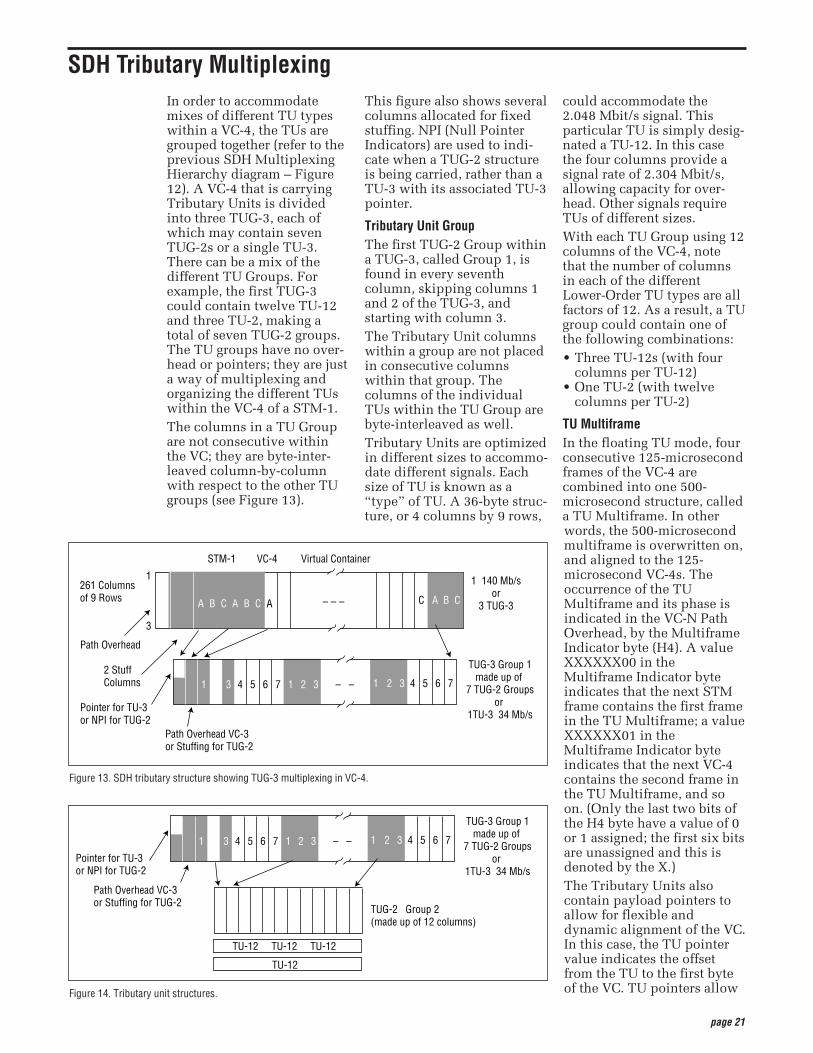
In order to accommodatemixes of different TU typeswithin a VC-4, the TUs aregrouped together (refer to theprevious SDH MultiplexingHierarchy diagram – Figure12). A VC-4 that is carryingTributary Units is dividedinto three TUG-3, each ofwhich may contain sevenTUG-2s or a single TU-3.There can be a mix of thedifferent TU Groups. Forexample, the first TUG-3could contain twelve TU-12and three TU-2, making atotal of seven TUG-2 groups.The TU groups have no over-head or pointers; they are justa way of multiplexing andorganizing the different TUswithin the VC-4 of a STM-1.The columns in a TU Groupare not consecutive withinthe VC; they are byte-inter-leaved column-by-columnwith respect to the other TUgroups (see Figure 13).
This figure also shows severalcolumns allocated for fixedstuffing. NPI (Null PointerIndicators) are used to indi-cate when a TUG-2 structureis being carried, rather than aTU-3 with its associated TU-3pointer.
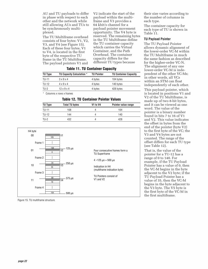
Tributary Unit GroupThe first TUG-2 Group withina TUG-3, called Group 1, isfound in every seventhcolumn, skipping columns 1and 2 of the TUG-3, andstarting with column 3.The Tributary Unit columnswithin a group are not placedin consecutive columnswithin that group. Thecolumns of the individualTUs within the TU Group arebyte-interleaved as well.Tributary Units are optimizedin different sizes to accommo-date different signals. Eachsize of TU is known as a“type” of TU. A 36-byte struc-ture, or 4 columns by 9 rows,
could accommodate the2.048 Mbit/s signal. Thisparticular TU is simply desig-nated a TU-12. In this casethe four columns provide asignal rate of 2.304 Mbit/s,allowing capacity for over-head. Other signals requireTUs of different sizes.With each TU Group using 12columns of the VC-4, notethat the number of columnsin each of the differentLower-Order TU types are allfactors of 12. As a result, a TUgroup could contain one ofthe following combinations:• Three TU-12s (with four
columns per TU-12)• One TU-2 (with twelve
columns per TU-2)
TU MultiframeIn the floating TU mode, fourconsecutive 125-microsecondframes of the VC-4 arecombined into one 500-microsecond structure, calleda TU Multiframe. In otherwords, the 500-microsecondmultiframe is overwritten on,and aligned to the 125-microsecond VC-4s. Theoccurrence of the TUMultiframe and its phase isindicated in the VC-N PathOverhead, by the MultiframeIndicator byte (H4). A valueXXXXXX00 in theMultiframe Indicator byteindicates that the next STMframe contains the first framein the TU Multiframe; a valueXXXXXX01 in theMultiframe Indicator byteindicates that the next VC-4contains the second frame inthe TU Multiframe, and soon. (Only the last two bits ofthe H4 byte have a value of 0or 1 assigned; the first six bitsare unassigned and this isdenoted by the X.) The Tributary Units alsocontain payload pointers toallow for flexible anddynamic alignment of the VC.In this case, the TU pointervalue indicates the offsetfrom the TU to the first byteof the VC. TU pointers allow
SDH Tributary Multiplexing
Figure 14. Tributary unit structures.
Pointer for TU-3or NPI for TUG-2
Path Overhead VC-3or Stuffing for TUG-2
TUG-3 Group 1made up of
7 TUG-2 Groupsor
1TU-3 34 Mb/s
1 3 4 5 6 7 1 2 3 – – 1 2 3 4 5 6 7
TUG-2 Group 2(made up of 12 columns)
TU-12 TU-12 TU-12
TU-12
Figure 13. SDH tributary structure showing TUG-3 multiplexing in VC-4.
STM-1 VC-4 Virtual Container
261 Columnsof 9 Rows
1 140 Mb/sor
3 TUG-3
Path Overhead
2 Stuff Columns
Pointer for TU-3or NPI for TUG-2
Path Overhead VC-3or Stuffing for TUG-2
TUG-3 Group 1made up of
7 TUG-2 Groupsor
1TU-3 34 Mb/s
1
3
A B C A B C A C A B C
1 3 4 5 6 7 1 2 3 – – 1 2 3 4 5 6 7
– – –
page 22
AU and TU payloads to differin phase with respect to eachother and the network whilestill allowing AUs and TUs tobe synchronously multi-plexed. The TU Multiframe overheadconsists of four bytes: V1, V2,V3, and V4 (see Figure 15).Each of these four bytes, V1to V4, is located in the firstbyte of the respective TUframe in the TU Multiframe.The payload pointers V1 and
V2 indicate the start of thepayload within the multi-frame and V3 provides a64 kbit/s channel for apayload pointer movementopportunity. The V4 byte isreserved. The remaining bytesin the TU Multiframe definethe TU container capacitywhich carries the VirtualContainer, and the PathOverhead. The containercapacity differs for thedifferent TU types because
their size varies according tothe number of columns ineach type.The container capacity foreach type of TU is shown inTable 11.
TU Payload PointerThe TU Payload Pointerallows dynamic alignment ofthe lower-order VC-M withinthe TU Multiframe in muchthe same fashion as describedfor the higher-order VC-N.The alignment of any onelower-order VC-M is inde-pendent of the other VC-Ms;in other words, all VCswithin an STM can floatindependently of each other.This payload pointer, whichis located in positions V1 andV2 of the TU Multiframe, ismade up of two 8-bit bytes,and it can be viewed as oneword. The value of thepointer is a binary numberfound in bits 7 to 16 of V1and V2. This value indicatesthe offset in bytes from theend of the pointer (byte V2)to the first byte of the VC; theV3 and V4 bytes are notcounted. The range of theoffset differs for each TU type(see Table 12).That is, the value of thepointer for a TU-12 has arange of 0 to 140. Forexample, if the TU PayloadPointer has a value of 0, thenthe VC-M begins in the byteadjacent to the V2 byte; if theTU Payload Pointer has avalue of 35, then the VC-Mbegins in the byte adjacent tothe V3 byte. The V5 byte isthe first byte of the VC-M inthe first multiframe.
Figure 15. TU multiframe structure.
Four consecutive frames form a TU Superframe
4 *125 µs = 500 µs
Indication in H4(multiframe indication byte)
TU Pointers consist ofV1 and V2
Frame 1
H4 byte
00105
V1
---
139 125 µs
Frame 2
010
V2
---
34 250 µs
Frame 3
1035
V3
---
69 375 µs
Frame 4
1170
V4
---
104 500 µs
Table 12. TU Container Pointer ValuesTU Type Total TU bytes V1 to V4 Pointer value range
TU-11 108 4 104
TU-12 144 4 140
TU-2 432 4 428
Table 11. TU Container CapacityTU Type TU Capacity Calculation * TU Pointer TU Container Capacity
TU-11 3 x 9 x 4 4 bytes 104 bytes
TU-12 4 x 9 x 4 4 bytes 140 bytes
TU-2 12 x 9 x 4 4 bytes 428 bytes
* Columns x rows x frames
page 23
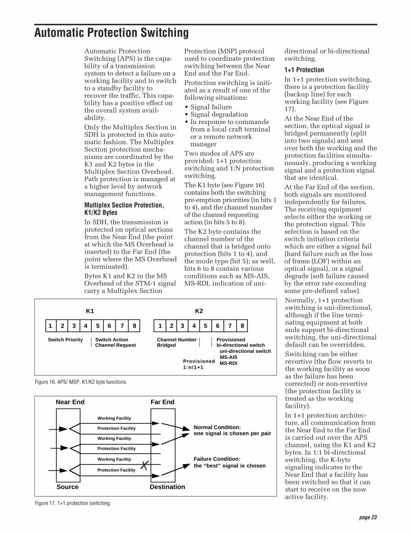
Automatic ProtectionSwitching (APS) is the capa-bility of a transmissionsystem to detect a failure on aworking facility and to switchto a standby facility torecover the traffic. This capa-bility has a positive effect onthe overall system avail-ability.Only the Multiplex Section inSDH is protected in this auto-matic fashion. The MultiplexSection protection mecha-nisms are coordinated by theK1 and K2 bytes in theMultiplex Section Overhead.Path protection is managed ata higher level by networkmanagement functions.
Multiplex Section Protection,K1/K2 BytesIn SDH, the transmission isprotected on optical sectionsfrom the Near End (the pointat which the MS Overhead isinserted) to the Far End (thepoint where the MS Overheadis terminated).Bytes K1 and K2 in the MSOverhead of the STM-1 signalcarry a Multiplex Section
Protection (MSP) protocolused to coordinate protectionswitching between the NearEnd and the Far End.Protection switching is initi-ated as a result of one of thefollowing situations: • Signal failure• Signal degradation• In response to commands
from a local craft terminalor a remote networkmanager
Two modes of APS areprovided: 1+1 protectionswitching and 1:N protectionswitching.The K1 byte (see Figure 16)contains both the switchingpre-emption priorities (in bits 1to 4), and the channel numberof the channel requestingaction (in bits 5 to 8). The K2 byte contains thechannel number of thechannel that is bridged ontoprotection (bits 1 to 4), andthe mode type (bit 5); as well,bits 6 to 8 contain variousconditions such as MS-AIS,MS-RDI, indication of uni-
directional or bi-directionalswitching.
1+1 ProtectionIn 1+1 protection switching,there is a protection facility(backup line) for eachworking facility (see Figure17).At the Near End of thesection, the optical signal isbridged permanently (splitinto two signals) and sentover both the working and theprotection facilities simulta-neously, producing a workingsignal and a protection signalthat are identical.At the Far End of the section,both signals are monitoredindependently for failures.The receiving equipmentselects either the working orthe protection signal. Thisselection is based on theswitch initiation criteriawhich are either a signal fail(hard failure such as the lossof frame (LOF) within anoptical signal), or a signaldegrade (soft failure causedby the error rate exceedingsome pre-defined value).Normally, 1+1 protectionswitching is uni-directional,although if the line termi-nating equipment at bothends support bi-directionalswitching, the uni-directionaldefault can be overridden.Switching can be eitherrevertive (the flow reverts tothe working facility as soonas the failure has beencorrected) or non-revertive(the protection facility istreated as the workingfacility).In 1+1 protection architec-ture, all communication fromthe Near End to the Far Endis carried out over the APSchannel, using the K1 and K2bytes. In 1:1 bi-directionalswitching, the K-bytesignaling indicates to theNear End that a facility hasbeen switched so that it canstart to receive on the nowactive facility.
Figure 16. APS/ MSP, K1/K2 byte functions.
K1 K2
1 2 3 4 5 6 7 8 1 2 3 4 5 6 7 8
Switch Priority Switch Action Channel Number Provisioned Channel Request Bridged bi-directional switch
uni-directional switch MS-AIS MS-RDIProvisioned1:n/1+1
Figure 17. 1+1 protection switching.
Near End Far End
Source Destination
Normal Condition:one signal is chosen per pair
Failure Condition:the “best” signal is chosen
Working Facility
Protection Facility
Working Facility
Protection Facility
Working Facility
Protection Facility
Automatic Protection Switching

page 24
1:N ProtectionIn 1:N protection switching,there is one protection facilityfor several working facilities(the range is from 1 to 14). In1:N protection architecture,all communication from theNear End to the Far End iscarried out over the APSchannel, using the K1 and K2bytes. All switching isrevertive; that is, the trafficreverts to the working facilityas soon as the failure hasbeen corrected.
In 1:N protection switching,optical signals are normallysent only over the workingfacilities, with the protectionfacility being kept free until aworking facility fails. Let’slook at a failure in a bi-direc-tional architecture (see Figure18). Suppose the Far Enddetects a failure on workingfacility 2. The Far End sendsa message in bits 5 to 8 of theK1 byte to the Near End overthe protection facilityrequesting switch action. TheNear End can act directly, orif there’s more than one
problem, the Near Enddecides which is top priority.On a decision to act on theproblem on working facility2, the Near End carries outthe following steps:1. Bridges working facility 2
at the Near End to theprotection facility.
2. Returns a message on theK2 byte indicating thechannel number of thetraffic on the protectionchannel to the Far End.
3. Sends a Reverse Request tothe Far End via the K1byte to initiate bi-direc-tional switch.
On receipt of this message,the Far End carries out thefollowing steps:1. Switches to the protection
facility to receive.2. Bridges working facility 2
to the protection facility totransmit back.
Now transmission is carriedout over the new workingfacility.
Figure 18. 1:N protection switching.
Near End Far End
Source Destination
Normal Condition:protection on channel empty
Failure Condition:protection channel containsfailed line
Working Facility
Protection Facilty
Working Facility
Protection Facility
page 25
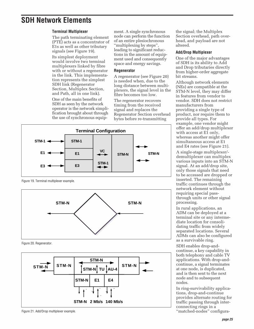
Terminal MultiplexerThe path terminating element(PTE) acts as a concentrator ofE1s as well as other tributarysignals (see Figure 19). Its simplest deploymentwould involve two terminalmultiplexers linked by fibrewith or without a regeneratorin the link. This implementa-tion represents the simplestSDH link (RegeneratorSection, Multiplex Section,and Path, all in one link).One of the main benefits ofSDH as seen by the networkoperator is the network simpli-fication brought about throughthe use of synchronous equip-
ment. A single synchronousnode can perform the functionof an entire plesiochronous“multiplexing by steps”,leading to significant reduc-tions in the amount of equip-ment used and consequentlyspace and energy savings.
RegeneratorA regenerator (see Figure 20)is needed when, due to thelong distance between multi-plexers, the signal level in thefibre becomes too low.The regenerator recoverstiming from the receivedsignal and replaces theRegenerator Section overheadbytes before re-transmitting
the signal; the MultiplexSection overhead, path over-head, and payload are notaltered.
Add/Drop MultiplexerOne of the major advantagesof SDH is its ability to Addand Drop tributaries directlyfrom higher-order aggregatebit streams. Although network elements(NEs) are compatible at theSTM-N level, they may differin features from vendor tovendor. SDH does not restrictmanufacturers fromproviding a single type ofproduct, nor require them toprovide all types. Forexample, one vendor mightoffer an add/drop multiplexerwith access at E1 only,whereas another might offersimultaneous access at E1and E4 rates (see Figure 21).A single-stage multiplexer/-demultiplexer can multiplexvarious inputs into an STM-Nsignal. At an add/drop site,only those signals that needto be accessed are dropped orinserted. The remainingtraffic continues through thenetwork element withoutrequiring special pass-through units or other signalprocessing.In rural applications, anADM can be deployed at aterminal site or any interme-diate location for consoli-dating traffic from widelyseparated locations. SeveralADMs can also be configuredas a survivable ring.SDH enables drop-and-continue, a key capability inboth telephony and cable TVapplications. With drop-and-continue, a signal terminatesat one node, is duplicated,and is then sent to the nextnode and to subsequentnodes.In ring-survivability applica-tions, drop-and-continueprovides alternate routing fortraffic passing through inter-connecting rings in a“matched-nodes” configura-
SDH Network Elements
Figure 19. Terminal multiplexer example.
E1
E3
STM-NVC
STM-1
E1
E3
STM-N
STM-1
Terminal Configuration
STM-1
Figure 20. Regenerator.
STM-NSTM-N
Figure 21. Add/Drop multiplexer example.
STM-N
STM-N
STM-N E1 E4
2 Mb/s 140 Mb/s
AU-4TUSTM-NSTM-N
STM-N
STM-N
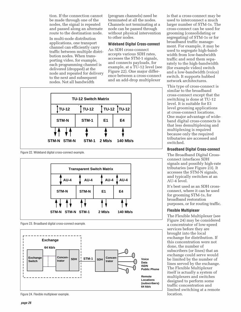
page 26
tion. If the connection cannotbe made through one of thenodes, the signal is repeatedand passed along an alternateroute to the destination node.In multi-node distributionapplications, one transportchannel can efficiently carrytraffic between multiple distri-bution nodes. When trans-porting video, for example,each programming channel isdelivered (dropped) at thenode and repeated for deliveryto the next and subsequentnodes. Not all bandwidth
(program channels) need beterminated at all the nodes.Channels not terminating at anode can be passed throughwithout physical interventionto other nodes.
Wideband Digital Cross-connectAn SDH cross-connectaccepts various SDH rates,accesses the STM-1 signals,and connects payloads, forexample, at a TU-12 level (seeFigure 22). One major differ-ence between a cross-connectand an add-drop multiplexer
is that a cross-connect may beused to interconnect a muchlarger number of STM-1s. Thecross-connect can be used forgrooming (consolidating orsegregating) of STM-1s or forbroadband traffic manage-ment. For example, it may beused to segregate high-band-width from low-bandwidthtraffic and send them sepa-rately to the high-bandwidth(for example video) switchand a low-bandwidth (voice)switch. It supports hubbednetwork architectures.This type of cross-connect issimilar to the broadbandcross-connect except that theswitching is done at TU-12level. It is suitable for E1level grooming applicationsat cross-connect locations.One major advantage of wide-band digital cross-connects isthat less demultiplexing andmultiplexing is requiredbecause only the requiredtributaries are accessed andswitched.
Broadband Digital Cross-connectThe Broadband Digital Cross-connect interfaces SDHsignals and possibly high-ratetributaries (see Figure 23). Itaccesses the STM-N signals,and typically switches at anAU-4 level.It’s best used as an SDH cross-connect, where it can be usedfor grooming STM-1s, forbroadband restorationpurposes, or for routing traffic.
Flexible MultiplexerThe Flexible Multiplexer (seeFigure 24) may be considereda concentrator of low-speedservices before they arebrought into the localexchange for distribution. Ifthis concentration were notdone, the number ofsubscribers (or lines) that anexchange could serve wouldbe limited by the number oflines served by the exchange.The Flexible Multiplexeritself is actually a system ofmultiplexers and switchesdesigned to perform sometraffic concentration andlimited switching at a remotelocation.
Figure 22. Wideband digital cross-connect example.
STM-1 2 Mb/s 140 Mb/sSTM-NSTM-N
STM-1 E1 E4STM-N
TU-12TU-12TU-12TU-12
TU-12 Switch Matrix
Figure 23. Broadband digital cross-connect example.
140 Mb/sSTM-N
STM-N E1 E4STM-N
AU-4AU-4
Transparent Switch Matrix
STM-N STM-1 2 Mb/s
AU-4 AU-4
Figure 24. Flexible multiplexer example.
ExchangeSwitch
64 kb/s
STM-1
RemoteLocations(subscribers)64 kb/s
SDHConcen-trator SDH
Concen-trator
Exchange
VoiceDataISDNPublic Phone
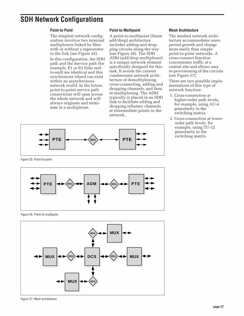
page 27
Point-to-PointThe simplest network config-uration involves two terminalmultiplexers linked by fibrewith or without a regeneratorin the link (see Figure 25). In this configuration, the SDHpath and the Service path (forexample, E1 or E3 links end-to-end) are identical and thissynchronous island can existwithin an asynchronousnetwork world. In the future,point-to-point service pathconnections will span acrossthe whole network and willalways originate and termi-nate in a multiplexer.
Point-to-MultipointA point-to-multipoint (linearadd/drop) architectureincludes adding and drop-ping circuits along the way(see Figure 26). The SDHADM (add/drop multiplexer)is a unique network elementspecifically designed for thistask. It avoids the currentcumbersome network archi-tecture of demultiplexing,cross-connecting, adding anddropping channels, and thenre-multiplexing. The ADMtypically is placed in an SDHlink to facilitate adding anddropping tributary channelsat intermediate points in thenetwork.
Mesh ArchitectureThe meshed network archi-tecture accommodates unex-pected growth and changemore easily than simplepoint-to-point networks. Across-connect functionconcentrates traffic at acentral site and allows easyre-provisioning of the circuits(see Figure 27). There are two possible imple-mentations of this type ofnetwork function:1. Cross-connection at
higher-order path levels,for example, using AU-4granularity in theswitching matrix.
2. Cross-connection at lower-order path levels, forexample, using TU-12granularity in theswitching matrix.
SDH Network Configurations
Figure 25. Point-to-point.
PTEPTE REG
Figure 27. Mesh architecture.
MUX
MUX
MUX
MUXDCS
REG
REGREG
REG
Figure 26. Point-to-multipoint.
REGPTE ADM PTEREG
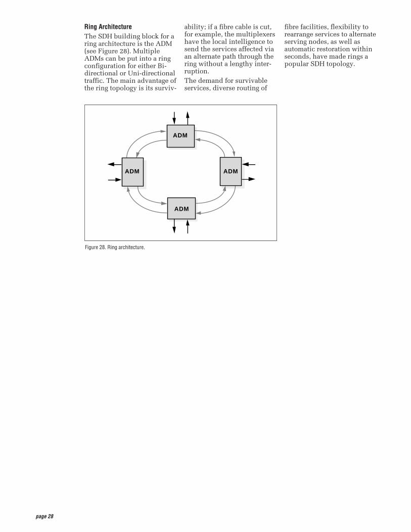
page 28
Ring ArchitectureThe SDH building block for aring architecture is the ADM(see Figure 28). MultipleADMs can be put into a ringconfiguration for either Bi-directional or Uni-directionaltraffic. The main advantage ofthe ring topology is its surviv-
ability; if a fibre cable is cut,for example, the multiplexershave the local intelligence tosend the services affected viaan alternate path through thering without a lengthy inter-ruption.The demand for survivableservices, diverse routing of
fibre facilities, flexibility torearrange services to alternateserving nodes, as well asautomatic restoration withinseconds, have made rings apopular SDH topology.
Figure 28. Ring architecture.
ADM
ADM
ADM
ADM
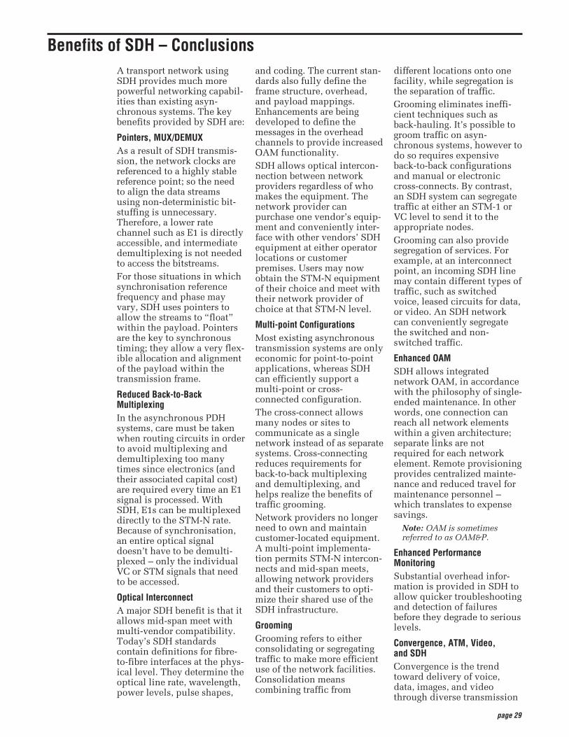
page 29
A transport network usingSDH provides much morepowerful networking capabil-ities than existing asyn-chronous systems. The keybenefits provided by SDH are:
Pointers, MUX/DEMUXAs a result of SDH transmis-sion, the network clocks arereferenced to a highly stablereference point; so the needto align the data streamsusing non-deterministic bit-stuffing is unnecessary.Therefore, a lower ratechannel such as E1 is directlyaccessible, and intermediatedemultiplexing is not neededto access the bitstreams. For those situations in whichsynchronisation referencefrequency and phase mayvary, SDH uses pointers toallow the streams to “float”within the payload. Pointersare the key to synchronoustiming; they allow a very flex-ible allocation and alignmentof the payload within thetransmission frame.
Reduced Back-to-BackMultiplexing In the asynchronous PDHsystems, care must be takenwhen routing circuits in orderto avoid multiplexing anddemultiplexing too manytimes since electronics (andtheir associated capital cost)are required every time an E1signal is processed. WithSDH, E1s can be multiplexeddirectly to the STM-N rate.Because of synchronisation,an entire optical signaldoesn’t have to be demulti-plexed – only the individualVC or STM signals that needto be accessed.
Optical Interconnect A major SDH benefit is that itallows mid-span meet withmulti-vendor compatibility.Today’s SDH standardscontain definitions for fibre-to-fibre interfaces at the phys-ical level. They determine theoptical line rate, wavelength,power levels, pulse shapes,
and coding. The current stan-dards also fully define theframe structure, overhead,and payload mappings.Enhancements are beingdeveloped to define themessages in the overheadchannels to provide increasedOAM functionality.SDH allows optical intercon-nection between networkproviders regardless of whomakes the equipment. Thenetwork provider canpurchase one vendor’s equip-ment and conveniently inter-face with other vendors’ SDHequipment at either operatorlocations or customerpremises. Users may nowobtain the STM-N equipmentof their choice and meet withtheir network provider ofchoice at that STM-N level.
Multi-point ConfigurationsMost existing asynchronoustransmission systems are onlyeconomic for point-to-pointapplications, whereas SDHcan efficiently support amulti-point or cross-connected configuration.The cross-connect allowsmany nodes or sites tocommunicate as a singlenetwork instead of as separatesystems. Cross-connectingreduces requirements forback-to-back multiplexingand demultiplexing, andhelps realize the benefits oftraffic grooming.Network providers no longerneed to own and maintaincustomer-located equipment.A multi-point implementa-tion permits STM-N intercon-nects and mid-span meets,allowing network providersand their customers to opti-mize their shared use of theSDH infrastructure.
GroomingGrooming refers to eitherconsolidating or segregatingtraffic to make more efficientuse of the network facilities.Consolidation meanscombining traffic from
different locations onto onefacility, while segregation isthe separation of traffic. Grooming eliminates ineffi-cient techniques such asback-hauling. It’s possible togroom traffic on asyn-chronous systems, however todo so requires expensiveback-to-back configurationsand manual or electroniccross-connects. By contrast,an SDH system can segregatetraffic at either an STM-1 orVC level to send it to theappropriate nodes.Grooming can also providesegregation of services. Forexample, at an interconnectpoint, an incoming SDH linemay contain different types oftraffic, such as switchedvoice, leased circuits for data,or video. An SDH networkcan conveniently segregatethe switched and non-switched traffic.
Enhanced OAMSDH allows integratednetwork OAM, in accordancewith the philosophy of single-ended maintenance. In otherwords, one connection canreach all network elementswithin a given architecture;separate links are notrequired for each networkelement. Remote provisioningprovides centralized mainte-nance and reduced travel formaintenance personnel –which translates to expensesavings.
Note: OAM is sometimesreferred to as OAM&P.
Enhanced PerformanceMonitoring Substantial overhead infor-mation is provided in SDH toallow quicker troubleshootingand detection of failuresbefore they degrade to seriouslevels.
Convergence, ATM, Video,and SDHConvergence is the trendtoward delivery of voice,data, images, and videothrough diverse transmission
Benefits of SDH – Conclusions
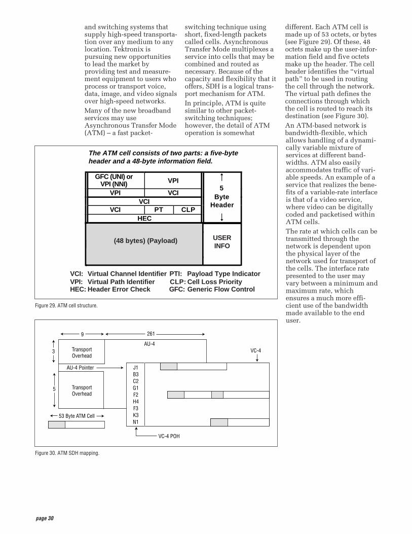
page 30
and switching systems thatsupply high-speed transporta-tion over any medium to anylocation. Tektronix ispursuing new opportunitiesto lead the market byproviding test and measure-ment equipment to users whoprocess or transport voice,data, image, and video signalsover high-speed networks.Many of the new broadbandservices may useAsynchronous Transfer Mode(ATM) – a fast packet-
switching technique usingshort, fixed-length packetscalled cells. AsynchronousTransfer Mode multiplexes aservice into cells that may becombined and routed asnecessary. Because of thecapacity and flexibility that itoffers, SDH is a logical trans-port mechanism for ATM.In principle, ATM is quitesimilar to other packet-switching techniques;however, the detail of ATMoperation is somewhat
different. Each ATM cell ismade up of 53 octets, or bytes(see Figure 29). Of these, 48octets make up the user-infor-mation field and five octetsmake up the header. The cellheader identifies the “virtualpath” to be used in routingthe cell through the network.The virtual path defines theconnections through whichthe cell is routed to reach itsdestination (see Figure 30).An ATM-based network isbandwidth-flexible, whichallows handling of a dynami-cally variable mixture ofservices at different band-widths. ATM also easilyaccommodates traffic of vari-able speeds. An example of aservice that realizes the bene-fits of a variable-rate interfaceis that of a video service,where video can be digitallycoded and packetised withinATM cells. The rate at which cells can betransmitted through thenetwork is dependent uponthe physical layer of thenetwork used for transport ofthe cells. The interface ratepresented to the user mayvary between a minimum andmaximum rate, whichensures a much more effi-cient use of the bandwidthmade available to the enduser.
Figure 29. ATM cell structure.
The ATM cell consists of two parts: a five-byte header and a 48-byte information field.
GFC (UNI) orVPI (NNI) VPI
VPI VCI5
VCIByte
VCI PT CLPHeader
HEC
(48 bytes) (Payload) USERINFO
GFC:
VCI: Virtual Channel Identifier PTI: Payload Type IndicatorVPI: Virtual Path Identifier CLP: Cell Loss PriorityHEC: Header Error Check Generic Flow Control
Figure 30. ATM SDH mapping.
261
AU-4
9
VC-4TransportOverhead
TransportOverhead
AU-4 Pointer
53 Byte ATM Cell
VC-4 POH
J1B3C2G1F2H4F3K3N1
3
5
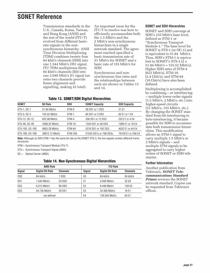
page 31
Transmission standards in theU.S., Canada, Korea, Taiwan,and Hong Kong (ANSI) andthe rest of the world (ITU-T)evolved from different basic-rate signals in the non-synchronous hierarchy. ANSITime Division Multiplexing(TDM) combines twenty four64 kbit/s channels (DS0) intoone 1.544 Mbit/s DS1 signal.ITU TDM multiplexes thirty64 kbit/s channels (E0) intoone 2.048 Mbit/s E1 signal (anextra two channels provideframe alignment andsignalling, making 32 total).
An important issue for theITU-T to resolve was how toefficiently accommodate boththe 1.5 Mbit/s and the2 Mbit/s non-synchronoushierarchies in a singlenetwork standard. The agree-ment reached specified abasic transmission rate of51 Mbit/s for SONET and abasic rate of 155 Mbit/s forSDH.Synchronous and non-synchronous line rates andthe relationships betweeneach are shown in Tables 13and 14.
SONET and SDH Hierarchies SONET and SDH converge atSDH’s 155 Mbit/s base level,defined as STM-1 or“Synchronous TransportModule-1.” The base level forSONET is STS-1 (or OC-1) andis equivalent to 51.84 Mbit/s.Thus, SDH’s STM-1 is equiva-lent to SONET’s STS-3 (3 x51.84 Mbit/s = 155.52 Mbit/s).Higher SDH rates of STM-4(622 Mbit/s), STM-16(2.4 Gbit/s), and STM-64(10 Gbit/s) have also beendefined.Multiplexing is accomplishedby combining – or interleaving– multiple lower-order signals(1.5 Mbit/s, 2 Mbit/s, etc.) intohigher-speed circuits(51 Mbit/s, 155 Mbit/s, etc.).By changing the SONET stan-dard from bit-interleaving tobyte-interleaving, it becamepossible for SDH to accommo-date both transmission hierar-chies. This modificationallows an STM-1 signal tocarry multiple 1.5 Mbit/s or2 Mbit/s signals – andmultiple STM signals to beaggregated to carry higherorders of SONET or SDH trib-utaries.
Further InformationAnother publication fromTektronix, SONET Tele-communications StandardPrimer reviews the SONETnetwork standard. Copies canbe requested from Tektronixoffices.
SONET Reference
Table 13. SONET/SDH Digital HierarchiesSONET Bit Rate SDH SONET Capacity SDH Capacity
STS-1, OC-1 51.84 Mbit/s STM-0 28 DS1 or 1 DS3 21 E1
STS-3, OC-3 155.52 Mbit/s STM-1 84 DS1 or 3 DS3 63 E1 or 1 E4
STS-12, OC-12 622.08 Mbit/s STM-4 336 DS1 or 12 DS3 252 E1 or 4 E4
STS-48, OC-48 2488.32 Mbit/s STM-16 1344 DS1 or 48 DS3 1008 E1 or 16 E4
STS-192, OC-192 9953.28 Mbit/s STM-64 5376 DS1 or 192 DS3 4032 E1 or 64 E4
STS-768, OC-768 39812.12 Mbit/s STM-256 21504 DS1s or 768 DS3s 16128 E1 or 256 E4
Note: Although an SDH STM-1 has the same bit rate as the SONET STS-3, the two signals contain different framestructures.STM = Synchronous Transport Module (ITU-T)STS = Synchronous Transport Signal (ANSI)OC = Optical Carrier (ANSI)
Table 14. Non-Synchronous Digital HierarchiesANSI Rate ITU Rate
Signal Digital Bit Rate Channels Signal Digital Bit Rate Channels
DS0 64 kbit/s 1 DS0 E0 64 kbit/s 64 kbit/s
DS1 1.544 Mbit/s 24 DS0 E1 2.048 Mbit/s 32 E0
DS2 6.312 Mbit/s 96 DS0 E2 8.448 Mbit/s 128 E0
DS3 44.736 Mbit/s 28 DS1 E3 34.368 Mbit/s 16 E1
not defined E4 139.264 Mbit/s 64 E1

page 32
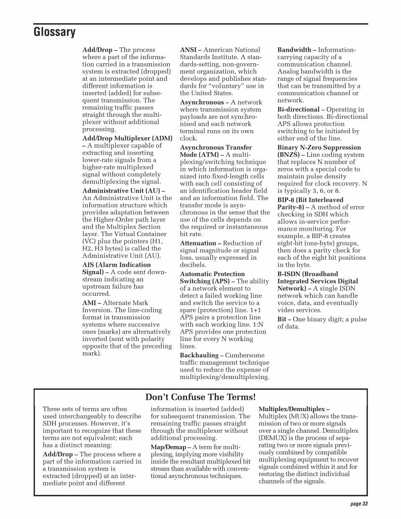
page 33
Three sets of terms are oftenused interchangeably to describeSDH processes. However, it’simportant to recognize that theseterms are not equivalent; eachhas a distinct meaning: Add/Drop – The process where apart of the information carried ina transmission system isextracted (dropped) at an inter-mediate point and different
information is inserted (added)for subsequent transmission. Theremaining traffic passes straightthrough the multiplexer withoutadditional processing.Map/Demap – A term for multi-plexing, implying more visibilityinside the resultant multiplexed bitstream than available with conven-tional asynchronous techniques.
Multiplex/Demultiplex –Multiplex (MUX) allows the trans-mission of two or more signalsover a single channel. Demultiplex(DEMUX) is the process of sepa-rating two or more signals previ-ously combined by compatiblemultiplexing equipment to recoversignals combined within it and forrestoring the distinct individualchannels of the signals.
Add/Drop – The processwhere a part of the informa-tion carried in a transmissionsystem is extracted (dropped)at an intermediate point anddifferent information isinserted (added) for subse-quent transmission. Theremaining traffic passesstraight through the multi-plexer without additionalprocessing.Add/Drop Multiplexer (ADM)– A multiplexer capable ofextracting and insertinglower-rate signals from ahigher-rate multiplexedsignal without completelydemultiplexing the signal.Administrative Unit (AU) –An Administrative Unit is theinformation structure whichprovides adaptation betweenthe Higher-Order path layerand the Multiplex Sectionlayer. The Virtual Container(VC) plus the pointers (H1,H2, H3 bytes) is called theAdministrative Unit (AU).AIS (Alarm IndicationSignal) – A code sent down-stream indicating anupstream failure hasoccurred. AMI – Alternate MarkInversion. The line-codingformat in transmissionsystems where successiveones (marks) are alternativelyinverted (sent with polarityopposite that of the precedingmark).
ANSI – American NationalStandards Institute. A stan-dards-setting, non-govern-ment organization, whichdevelops and publishes stan-dards for “voluntary” use inthe United States. Asynchronous – A networkwhere transmission systempayloads are not synchro-nised and each networkterminal runs on its ownclock.Asynchronous TransferMode (ATM) – A multi-plexing/switching techniquein which information is orga-nized into fixed-length cellswith each cell consisting ofan identification header fieldand an information field. Thetransfer mode is asyn-chronous in the sense that theuse of the cells depends onthe required or instantaneousbit rate.Attenuation – Reduction ofsignal magnitude or signalloss, usually expressed indecibels.Automatic ProtectionSwitching (APS) – The abilityof a network element todetect a failed working lineand switch the service to aspare (protection) line. 1+1APS pairs a protection linewith each working line. 1:NAPS provides one protectionline for every N workinglines.Backhauling – Cumbersometraffic management techniqueused to reduce the expense ofmultiplexing/demultiplexing.
Bandwidth – Information-carrying capacity of acommunication channel.Analog bandwidth is therange of signal frequenciesthat can be transmitted by acommunication channel ornetwork.Bi-directional – Operating inboth directions. Bi-directionalAPS allows protectionswitching to be initiated byeither end of the line.Binary N-Zero Suppression(BNZS) – Line coding systemthat replaces N number ofzeros with a special code tomaintain pulse densityrequired for clock recovery. Nis typically 3, 6, or 8.BIP-8 (Bit InterleavedParity-8) – A method of errorchecking in SDH whichallows in-service perfor-mance monitoring. Forexample, a BIP-8 createseight-bit (one-byte) groups,then does a parity check foreach of the eight bit positionsin the byte.B-ISDN (BroadbandIntegrated Services DigitalNetwork) – A single ISDNnetwork which can handlevoice, data, and eventuallyvideo services.Bit – One binary digit; a pulseof data.
Glossary
Don’t Confuse The Terms!
page 34
Bit Error Rate (BER) – Thenumber of bit errors detectedin a unit of time, usually onesecond. Bit Error rate (BER) iscalculated with the formula:
BER = errored bits received/totalbits sent
Block Error rate (BLER) –One of the underlyingconcepts of error performanceis the notion of ErroredBlocks; i.e., blocks in whichone or more bits are in error.A block is a set of consecutivebits associated with the pathor section monitored bymeans of an Error DetectionCode (EDC), such as BitInterleaved Parity (BIP).Block Error rate (BLER) iscalculated with the formula:
BLER = errored blocksreceived/total blocks sent
Bit-Interleaved Parity (BIP) –A parity check that groups allthe bits in a block into units(such as byte), then performsa parity check for each bitposition in the group.Bit-Stuffing – In asyn-chronous systems, a tech-nique used to synchroniseasynchronous signals to acommon rate before multi-plexing.Bits per second (bit/s) – Thenumber of bits passing apoint every second. Thetransmission rate for digitalinformation.Broadband – Servicesrequiring over 2 Mbit/s trans-port capacity.CCITT – Former name of ITU.Channel – The smallestsubdivision of a circuit thatprovides a type of communi-cation service; usually a pathwith only one direction.Circuit – A communicationspath or network; usually apair of channels providing bi-directional communication.Circuit Switching – Basicswitching process whereby acircuit between two users isopened on demand and main-tained for their exclusive usefor the duration of the trans-mission.
Coding Violation (CV) – Atransmission error detectedby the difference between thetransmitted line code and thatexpected at the receive endby the logical coding rules.Concatenation – The linkingtogether of various data struc-tures, for example two chan-nels joined to form a singlechannel. In SDH, a number(M) of TUs can be linkedtogether to produce a concate-nated container, M times thesize of the TU. An example ofthis is the concatenation offive TU-2s to carry a32 Mbit/s video signal,known as VC-2-5c. Onceassembled, any concatenatedVC structure is multiplexed,switched, and transportedthrough the network as asingle entity.Cyclic Redundancy Check(CRC) – A technique for usingoverhead bits to detect trans-mission errors. Data CommunicationsChannel (DCC) – Data chan-nels in SDH that enable OAMcommunications betweenintelligent controllers andindividual network nodes aswell as inter-node communi-cations.Defect – A limited interrup-tion in the ability of an itemto perform a required func-tion. Persistence of a defectcan cause a failure.Demultiplex (DEMUX) – Toseparate two or more signalspreviously combined bycompatible multiplexingequipment to recover signalscombined within it and forrestoring the distinct indi-vidual channels of thesignals.Dense Wavelength DivisionMultiplexing (DWDM) –DWDM is the higher capacityversion of WDM, which is ameans of increasing thecapacity of fibre-optic datatransmission systems throughthe multiplexing of multiplewavelengths of light.Commercially availableDWDM systems support themultiplexing of from 8 to 40wavelengths of light.
Digital Cross-connect (DCS) –An electronic cross-connectwhich has access to lower-rate channels in higher-ratemultiplexed signals and canelectronically rearrange(cross-connect) those chan-nels.Digital Signal – An electricalor optical signal that varies indiscrete steps. Electricalsignals are coded as voltages,optical signals are coded aspulses of light.ETSI (EuropeanTelecommunicationsStandards Institute) –Organization responsible fordefining and maintainingEuropean standards,including SDH.Failure – A termination of theability of an item to perform arequired function. A failure iscaused by the persistence of adefect.FEBE (Far End Block Error) –See Remote Error Indication(REI).FERF (Far End ReceiveFailure) – See Remote DefectIndication (RDI).Fixed Stuff – A bit or bytewhose function is reserved.Fixed stuff locations, some-times called reserved loca-tions, do not carry overheador payload.Floating Mode – A tributarymode that allows thesynchronous payload to beginanywhere in the VC. Pointersidentify the starting locationof the LO-VC. LO-VCs indifferent multiframes maybegin at different locations.Framing – Method of distin-guishing digital channels thathave been multiplexedtogether.Frequency – The number ofcycles of periodic activitythat occur in a discreteamount of time.Grooming – Consolidating orsegregating traffic for effi-ciency.HDB3 – High DensityBipolar 3. A bipolar codingmethod that does not allowmore than three consecutivezeros.

page 35
ITU (InternationalTelecommunication Union) –An agency of the UnitedNations responsible for theregulation, standardization,coordination, and develop-ment of international telecom-munications as well as theharmonization of nationalpolicies. It functions throughinternational committees oftelecommunications adminis-trations, operators, manufac-turers, and scientific/indus-trial organizations.Jitter – The short-term varia-tions of the significantinstants of a timing signalfrom their ideal positions intime (where short termimplies that these variationsare of frequency greater thanor equal to 10 Hz). Locked Mode – A virtual trib-utary mode that fixes thestarting location of the VC.Locked mode has less pointerprocessing than floatingmode.Map/Demap – A term formultiplexing, implying morevisibility inside the resultantmultiplexed bit stream thanavailable with conventionalasynchronous techniques.Mapping – The process ofassociating each bit trans-mitted by a service into theSDH payload structure thatcarries the service. Forexample, mapping an E1service into an SDH VC-12associates each bit of the E1with a location in the VC-12.Multiframe – Any structuremade up of multiple frames.SDH has facilities to recog-nize multiframes at the E1level and at the VC-N level.
Multiplex Section AlarmIndication Signal (MS-AIS) –MS-AIS is generated bySection TerminatingEquipment (STE) upon thedetection of a Loss of Signalor Loss of Frame defect, on anequipment failure. MS-AISmaintains operation of thedownstream regenerators,and therefore prevents gener-ation of unnecessary alarms.At the same time, data andorderwire communication isretained with the downstreamequipment.Multiplex Section RemoteDefect Indication (MS-RDI) –A signal returned to the trans-mitting equipment upondetecting a Loss of Signal,Loss of Frame, or MS-AISdefect. MS-RDI was previ-ously known as MultiplexSection FERF.Multiplex Section Overhead(MSOH) – 18 bytes of over-head accessed, generated, andprocessed by MS terminatingequipment. This overheadsupports functions such aslocating the payload in theframe, multiplexing orconcatenating signals, perfor-mance monitoring, automaticprotection switching, and linemaintenance.Multiplex (MUX) – Totransmit two or more signalsover a single channel. Multiplexer – A device forcombining several channelsto be carried by a single phys-ical channel.Narrowband – Servicesrequiring up to 2 Mbit/stransport capacity.Network Element (NE) – Anydevice which is part of anSDH transmission path andserves one or more of thesection, line and path-termi-nating functions.In SDH, the five basicnetwork elements are:• Add/drop multiplexer• Broadband digital cross-
connect• Wideband digital cross-
connect• Flexible multiplexer• Regenerator
OAM – Operations,Administration, andMaintenance. Also calledOAM&P.OAM&P (Operations,Administration,Maintenance, andProvisioning) – Provides thefacilities and personnelrequired to manage anetwork.Optical Amplifier – A deviceto amplify an optical signalwithout converting the signalfrom optical to electrical andback again to optical energy.The two most commonoptical amplifiers are erbium-doped fibre amplifiers(EDFAs), which amplify witha laser pump diode and asection of erbium-dopedfibre, and semiconductorlaser amplifiers.Orderwire – A dedicatedvoice channel used byinstallers to expedite theprovisioning of lines.OS (Operations System) –Sophisticated applicationssoftware that manages opera-tion of the entire network.OSI Seven-layer Model – Astandard architecture for datacommunications. Layersdefine hardware and softwarerequired for multi-vendorinformation processingequipment to be mutuallycompatible. The seven layersfrom lowest to highest are:physical, link, network, trans-port, session, presentation,and application.Overhead – Extra bits in adigital stream used to carryinformation besides trafficsignals. Orderwire, forexample, would be consid-ered overhead information.Packet Switching – An effi-cient method for breakingdown and handling high-volume traffic in a network. Atransmission technique thatsegments and routes informa-tion into discrete units.Packet switching allows forefficient sharing of networkresources as packets fromdifferent sources can all besent over the same channel inthe same bitstream.
page 36
Parity Check – An error-checking scheme whichexamines the number oftransmitted bits in a blockwhich hold the value of“one.” For even parity, anoverhead parity bit is set toeither one or zero to make thetotal number of transmittedones in the data block plusparity bit an even number.For odd parity, the parity bitis set to make the totalnumber of ones in the blockan odd number.Path – A logical connectionbetween a point where aservice in a VC is multiplexedto the point where it isdemultiplexed.Path Overhead (POH) –Overhead accessed, gener-ated, and processed by path-terminating equipment.Path Terminating Equipment(PTE) – Network elementssuch as fibre optic termi-nating systems which canaccess, generate, and processPath Overhead.Payload – The portion of theSDH signal available to carryservice signals such as E1 andE3. The contents of a VC.Payload Pointer – Indicatesthe beginning of a VirtualContainer.Payload Capacity – Thenumber of bytes the payloadof a single frame can carry.Plesiochronous – A networkwith nodes timed by separateclock sources with almost thesame timing.Pointer – A part of the SDHoverhead that locates afloating payload structure.AU-N pointers locate thepayload. TU-M pointerslocate floating mode tribu-taries. All SDH frames useAU pointers; only floatingmode virtual containers useTU pointers.POP (Point-of-Presence) – Apoint in the U.S. networkwhere inter-exchange carrierfacilities meet with accessfacilities managed by tele-phone companies or otherservice providers.
PRC (Primary ReferenceClock) – In a synchronousnetwork, all the clocks aretraceable to one highly stablereference supply, the PrimaryReference Clock (PRC). Theaccuracy of the PRC is betterthan ±1 in 1011 and is derivedfrom a cesium atomic stan-dard.Remote Alarm Indication(RAI) – A code sent upstreamon an En circuit as a notifica-tion that a failure condition hasbeen declared downstream.(RAI signals were previouslyreferred to as Yellow signals.)Remote Defect Indication(RDI) – A signal returned tothe transmitting TerminatingEquipment when thereceiving TerminatingEquipment detects a Loss ofSignal, Loss of Frame, or AISdefect. RDI was previouslyknown as Far End ReceiveFailure (FERF).Remote Error Indication(REI) – An indicationreturned to a transmittingnode (source) that an erroredblock has been detected at thereceiving node (sink). REIwas previously known as FarEnd Block Error (FEBE).Remote Failure Indication(RFI) – A failure is a defectthat persists beyond themaximum time allocated tothe transmission systemprotection mechanisms. Whenthis situation occurs, an RFI issent to the far end and willinitiate a protection switch ifthis function has beenenabled. Regenerator – Device thatrestores a degraded digitalsignal for continued transmis-sion; also called a repeater.SDH (Synchronous DigitalHierarchy) – The ITU-definedinternational networkingstandard whose base trans-mission level is 155 Mbit/s(STM-1). SDH standards werefirst published in 1989 toaddress interworkingbetween the ITU and ANSItransmission hierarchies.
SEC (SynchronousEquipment Clock) – G.813slave clock contained withinan SDH network element.Section – The span betweentwo SDH network elementscapable of accessing, gener-ating, and processing onlySDH Section overhead.Section Overhead – Ninecolumns of SDH overheadaccessed, generated, andprocessed by section termi-nating equipment. This over-head supports functions suchas framing the signal andperformance monitoring.Section TerminatingEquipment (STE) –Equipment that terminatesthe SDH Section layer. STEinterprets and modifies orcreates the Section Overhead.Slip – An overflow (deletion)or underflow (repetition) ofone frame of a signal in areceiving buffer.SONET (SynchronousOptical Network) – A stan-dard for optical transport inthe United States, Canada,Korea, and Hong Kong thatdefines optical carrier levelsand their electrically equiva-lent synchronous transportsignals. SONET allows for amulti-vendor environmentand positions the network fortransport of new services,synchronous networking, andenhanced OAM&P.SSM (Synchronisation StatusMessage) – Bits 5 to 8 of SDHoverhead byte S1 are allo-cated for SynchronisationStatus Messages. For furtherdetails on the assignment ofbit patterns for byte S1, seethe section of this primer onMultiplex Section Overhead.Stuffing – See bit-stuffing.Synchronous – A networkwhere transmission systempayloads are synchronised toa master (network) clock andtraceable to a reference clock.A network where all clockshave the same long termaccuracy under normal oper-ating conditions.Synchronisation Supply Unit(SSU) – A G.812 networkequipment clock.
page 37
Synchronous TransportModule (STM) – A structurein the SDH transmission hier-archy. STM-1 is SDH’s base-level transmission rate equalto 155.52 Mbit/s. Higher ratesof STM-4, STM-16, andSTM-64 are also defined.Tributary Unit (TU) – ATributary Unit is an informa-tion structure which providesadaptation between theLower-Order path layer andthe Higher-Order path layer.It contains the VirtualContainer (VC) plus a tribu-tary unit pointer.
Tributary Unit Group (TUG)– Contains several TributaryUnits.Virtual Container (VC) – Asignal designed for transportand switching of sub-SDHpayloads.Wander – The long-term vari-ations of the significantinstants of a digital signalfrom their ideal position intime (where long termimplies that these variationsare of frequency less than10 Hz).
Wavelength DivisionMultiplexing (WDM) – WDMis a means of increasing thecapacity of fibre-optic datatransmission systems throughthe multiplexing of multiplewavelengths of light. WDMsystems support the multi-plexing of as many as fourwavelengths.Yellow Signal – See RemoteAlarm Indication (RAI).

page 38
page 39
ITU-T:• G.701 – Vocabulary of
digital transmission andmultiplexing and PCMterms
• G.702 – Digital Hierarchybit rates
• G.703 – Physical/electricalcharacteristics of hierar-chical digital interfaces
• G.704 – Synchronous framestructures used at 1544,6312, 2048, 8448, and44736 kbit/s hierarchicallevels
• G.706 – Frame alignmentand cyclic redundancycheck (CRC) proceduresrelating to basic framestructures defined inRecommendation G.704
• G.707 – Network NodeInterface for the SDH
• G.772 – Protected moni-toring points provided ondigital transmissionsystems
• G.780 – Vocabulary ofterms for SDH networksand equipment
• G.783 – Characteristics ofSDH equipment functionalblocks
• G.784 – SDH management
• G.803 – Architecture oftransport networks basedon the SDH
• G.823 – Control of jitter andwander in PDH systems
• G.825 – Control of jitter andwander in SDH systems
• G.826 – Error performanceparameters and objectivesfor international, constantbit rate digital paths at orabove the primary rate
• G.827 – Availability param-eters and objectives for pathelements of internationalconstant bit-rate digitalpaths at or above theprimary rate
• G.831 – Management capa-bilities of transport networkbased on SDH
• G.841 – Types and charac-teristics of SDH networkprotection architectures
• G.861 – Principles andguidelines for the integra-tion of satellite and radiosystems in SDH
• G.957 – Optical interfacesfor equipment and systemsrelating to the SDH
• G.958 – Digital line systemsbased on SDH for use onoptical fibre cables
• I.432 – B-ISDN user-network interface –Physical layer specification
• M.2100 – Performancelimits for bringing-into-service and maintenance ofinternational digital paths,sections, and transmissionsystems
• M.2101 – Performancelimits for BIS and mainte-nance of SDH paths andmultiplex sections
• O.150 – General require-ments for instrumentationfor performance measure-ments on digital transmis-sion equipment
• O.172 – Jitter and wandermeasuring equipment fordigital systems which arebased on the SynchronousDigital Hierarchy (SDH)
• O.181 – Equipment toassess error performance onSTM-N interfaces
• F.750 (ITU-R) –Architectures and func-tional aspects of radio-relaysystems for SDH-basednetworks
SDH Reference Materials

page 40


0200 TD/XBS 2RX–11694–1
Copyright © 2000, Tektronix, Inc. All rights reserved. Tektronix products are covered by U.S. and foreign patents, issued and pending. Information in thispublication supersedes that in all previously published material. Specification and price change privileges reserved. TEKTRONIX and TEK are registeredtrademarks of Tektronix, Inc. All other trade names referenced are the service marks, trademarks, or registered trademarks of their respective companies.
For further information, contact Tektronix:Worldwide Web: For the most up-to-date product information, visit our web site at www.tektronix.com.
ASEAN Countries (65) 356-3900; Australia & New Zealand 61 (2) 9888-0100; Austria, Central Eastern Europe, Greece, Turkey, Malta, & Cyprus +43 2236 8092 0; Belgium +32 (2) 715 89 70;Brazil and South America 55 (11) 3741-8360; Canada 1 (800) 661-5625; Denmark +45 (44) 850 700; Finland +358 (9) 4783 400; France & North Africa +33 1 69 86 81 81; Germany + 49 (221) 94 77 400; Hong Kong (852) 2585-6688; India (91) 80-2275577; Italy +39 (2) 25086 501; Japan (Sony/Tektronix Corporation) 81 (3) 3448-3111; Mexico, Central America, & Caribbean 52 (5) 666-6333; The Netherlands +31 23 56 95555; Norway +47 22 07 07 00; People’s Republic of China 86 (10) 6235 1230; Republic of Korea 82 (2) 528-5299; South Africa (27 11) 651-5222; Spain & Portugal +34 91 372 6000;Sweden +46 8 477 65 00; Switzerland +41 (41) 729 36 40; Taiwan 886 (2) 2722-9622; United Kingdom & Eire +44 (0) 1344 392000; USA 1 (800) 426-2200.
From other areas, contact: Tektronix, Inc. Export Sales, P.O. Box 500, M/S 50-255, Beaverton, Oregon 97077-0001, USA 1 (503) 627-6877.


![European Standard (Telecommunications series) · [11] ITU-T Recommendation M.2101: "Performance limits for bringing-into-service and maintenance of international SDH paths, sections](https://img.pdfslide.us/doc/110x75/5c64185509d3f26b1f8c35e9/european-standard-telecommunications-series-11-itu-t-recommendation-m2101.jpg)