Embed Size (px)
DESCRIPTION
Technical Training Autumn 2004. SR 50 i.e. 2005 (Ditech and C361M). Content. SR 50 i.e. 2005 (Ditech and C361M) Vehicles and identification numbers Design Dashboard and immobilizer Updates on injection system New components. Vehicles and identification numbers. - PowerPoint PPT Presentation
Citation preview

1
Technical Training Autumn 2004
SR 50 i.e. 2005 (Ditech and C361M)SR 50 i.e. 2005 (Ditech and C361M)

2
ContentContent
SR 50 i.e. 2005 (Ditech and C361M) SR 50 i.e. 2005 (Ditech and C361M)
Vehicles and identification numbersVehicles and identification numbers
DesignDesign
Dashboard and immobilizer Dashboard and immobilizer
Updates on injection systemUpdates on injection system
New componentsNew components
3
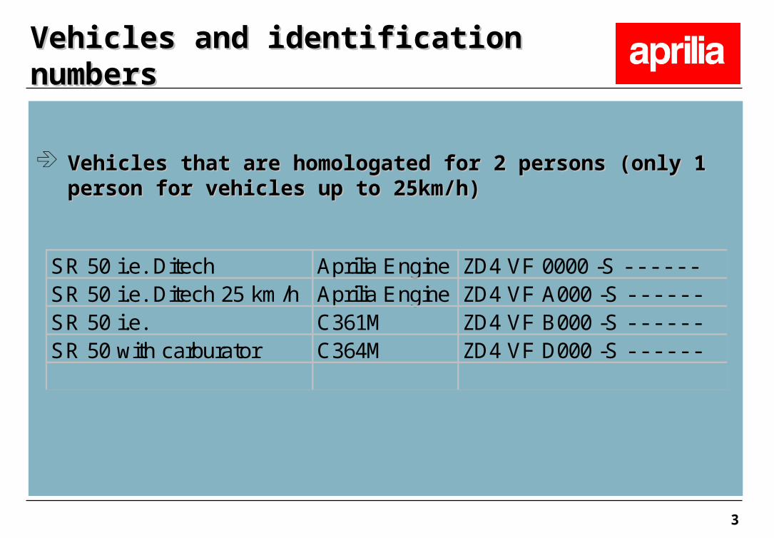
Vehicles that are homologated for 2 persons (only 1 person for Vehicles that are homologated for 2 persons (only 1 person for vehicles up to 25km/h)vehicles up to 25km/h)
Vehicles and identification numbersVehicles and identification numbers
SR 50 i.e. Ditech Aprilia Engine ZD4 VF 0000 -S - - - - - - SR 50 i.e. Ditech 25 km/h Aprilia Engine ZD4 VF A000 -S - - - - - - SR 50 i.e. C361M ZD4 VF B000 -S - - - - - - SR 50 with carburator C364M ZD4 VF D000 -S - - - - - -

4
Design and main components: Design and main components: side viewside view
1) Coolant reservoir
3) Brake fluid reservoir
5) Mix oil reservoir
6) Seat lock
8) Fuel tank
10) Air filter
5
Design and main components:Design and main components:side viewside view
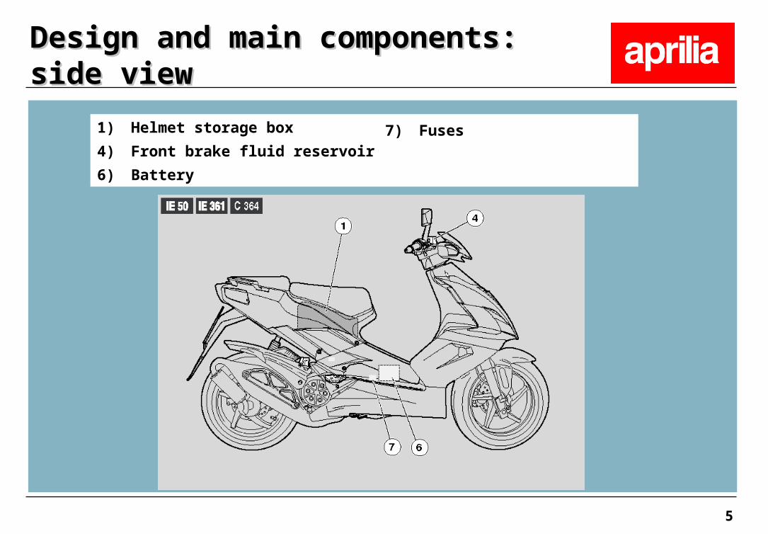
1) Helmet storage box
4) Front brake fluid reservoir
6) Battery
7) Fuses

6
Located behind the Located behind the left turn-signalleft turn-signalIndicator. Indicator. Remove screw of the Remove screw of the cover to access the cover to access the connector.connector.
Design and main components: DLCDesign and main components: DLC

7
Active speed sensor Active speed sensor with 3 connections: with 3 connections: supply voltage, supply voltage, ground, signal output.ground, signal output.
Design and main components: Design and main components: vehicle speed sensorvehicle speed sensor
8
Main new feature of SR 50 i.e. (Ditech and C361M) Main new feature of SR 50 i.e. (Ditech and C361M)
DashboardDashboard
1) Tachometer
2) Fuel level indicator
3) Coolant temperature
7) Clock
8) Speedometer
9) Odometer
10) Trip meter
11) Multi-functional indicator: time per trip, highest average vehicle speed
12) General warning light

9
DashboardDashboard

10
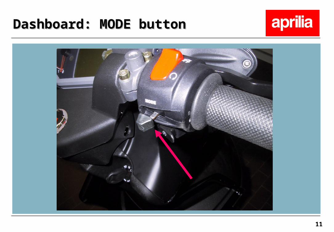
The MODE button controls several functions on the display and The MODE button controls several functions on the display and works like a turn-signal switch (move left, move right, press).works like a turn-signal switch (move left, move right, press).
Dashboard: MODE buttonDashboard: MODE button
11
Dashboard: MODE buttonDashboard: MODE button

12
Use of MODE buttonUse of MODE button
By moving the button to the right or left, you can scroll through the By moving the button to the right or left, you can scroll through the functions on the display. By pressing the button you select the function. functions on the display. By pressing the button you select the function. By continuously pressing the button, you confirm your choice.By continuously pressing the button, you confirm your choice.
Sequence of functions:Sequence of functions:TRIP 1TRIP 1 TRIP 2 TRIP 2 BATTERY VOLTAGE BATTERY VOLTAGE CLOCK CLOCK MENU MENU
For details on the functions (except the menu) refer to the For details on the functions (except the menu) refer to the documentation.documentation.
Dashboard: MODE buttonDashboard: MODE button
13
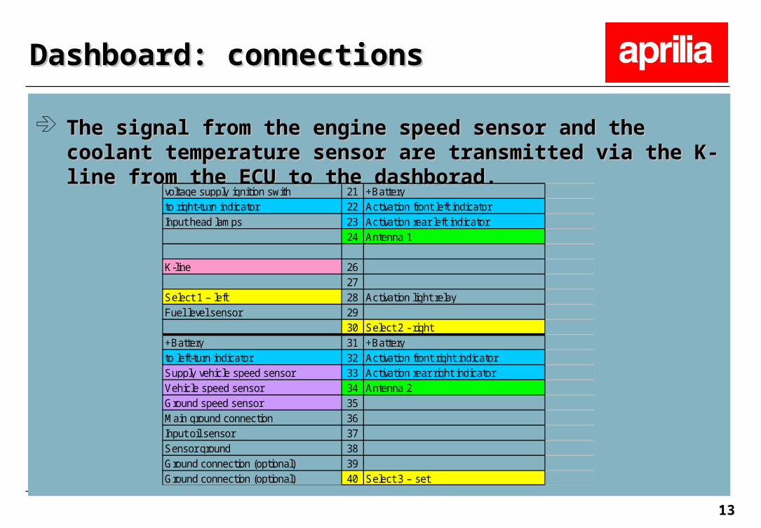
The signal from the engine speed sensor and the coolant The signal from the engine speed sensor and the coolant temperature sensor are transmitted via the K-line from the ECU to temperature sensor are transmitted via the K-line from the ECU to the dashborad.the dashborad.
Dashboard: connectionsDashboard: connections
voltage supply ignition swith 21 +Batteryto right-turn indicator 22 Activation front left indicatorInput head lamps 23 Activation rear left indicator
24 Antenna 1
K-line 2627
Select 1 – left 28 Activation light relayFuel level sensor 29
30 Select 2 - right+Battery 31 +Batteryto left-turn indicator 32 Activation front right indicatorSupply vehicle speed sensor 33 Activation rear right indicatorVehicle speed sensor 34 Antenna 2Ground speed sensor 35Main ground connection 36Input oil sensor 37Sensor ground 38Ground connection (optional) 39Ground connection (optional) 40 Select 3 – set
14
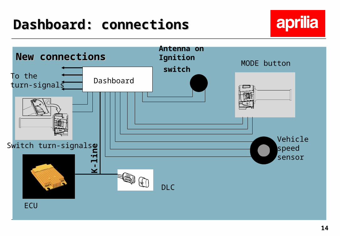
New connectionsNew connections
Dashboard: connectionsDashboard: connections
To the turn-signals
Vehiclespeed sensor
Dashboard
DLC
ECU
Antenna on Ignition
switchMODE button
Switch turn-signals
K-l
ine

15
The immobilizer system is integrated into the dashboard map. The immobilizer system is integrated into the dashboard map.
When switching ignition on, the key-code is read. If the code When switching ignition on, the key-code is read. If the code corresponds to one of the code in the dashboard memory, the corresponds to one of the code in the dashboard memory, the dashboard starts the initial check and transmits the signal to start dashboard starts the initial check and transmits the signal to start the engine to the ECU via the K-line.the engine to the ECU via the K-line.
If the code does not correspond, the engine is not started and the If the code does not correspond, the engine is not started and the request to type in the code manually appears on the display.request to type in the code manually appears on the display.
Dashboard: ImmobilizerDashboard: Immobilizer

16
Each customer receives two keys pre-coded transponders. Every Each customer receives two keys pre-coded transponders. Every time the ingition is switched on, the request to type in the 5-digit time the ingition is switched on, the request to type in the 5-digit personal code appears on the display for 30 seconds.personal code appears on the display for 30 seconds.
Make sure to input the customer codeMake sure to input the customer code
To input the code, the function CODE MODIFICATION needs to be To input the code, the function CODE MODIFICATION needs to be selected.(See page 18)selected.(See page 18)
Dashboard: ImmobilizerDashboard: Immobilizer
17
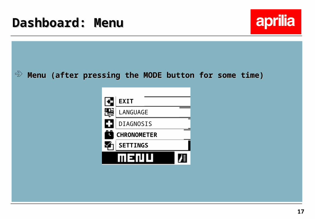
Menu (after pressing the MODE button for some time)Menu (after pressing the MODE button for some time)
Dashboard: Menu Dashboard: Menu
EXIT
LANGUAGE
DIAGNOSIS
CHRONOMETER
SETTINGS

18
The settings menu allows the customer to set the clock and to The settings menu allows the customer to set the clock and to modify the code.modify the code.
The menu point CODE MODIFICATION allows the customer to The menu point CODE MODIFICATION allows the customer to change the code. change the code. The old code must be typed in first, then the new code can be The old code must be typed in first, then the new code can be entered. entered. For new vehicles the initial code is 00000.For new vehicles the initial code is 00000.
For more details, check the documentation.For more details, check the documentation.
Dashboard: SettingsDashboard: Settings
19
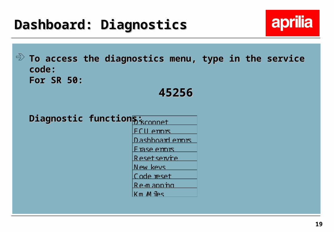
To access the diagnostics menu, type in the service code:To access the diagnostics menu, type in the service code:For SR 50:For SR 50:
4525645256
Diagnostic functions:Diagnostic functions:
Dashboard: DiagnosticsDashboard: Diagnostics
DisconnetECU errorsDashboard errorsErase errorsReset serviceNew keysCode resetRe-mappingKm/Miles

20
NEW KEYS function: NEW KEYS function:
Use this function to:Use this function to:1) disable a key in case the key gets lost1) disable a key in case the key gets lost2) program 2 additional keys (max. no of keys per vehicle: 4)2) program 2 additional keys (max. no of keys per vehicle: 4)3) enable new keys when the ignition switch has been changed3) enable new keys when the ignition switch has been changed
First type in the customer code, then, after having had First type in the customer code, then, after having had memorisation confirm of the inserted key (the 1st key), insert the memorisation confirm of the inserted key (the 1st key), insert the others keys you want to program.others keys you want to program.
The procedure is finished after a maximum of 4 keys or after 20 The procedure is finished after a maximum of 4 keys or after 20 seconds. seconds.
Dashboard: DiagnosticsDashboard: Diagnostics

21
MODIFY KEYS function:MODIFY KEYS function:
In case of using a new ignition switch, follow these procedure:In case of using a new ignition switch, follow these procedure:
Turn key ON, the dashboard don’t recognize the key and ask Turn key ON, the dashboard don’t recognize the key and ask owner code. Insert owner code. owner code. Insert owner code.
Now, it’s possible to enter in: MENU, DIAGNOSIS (inserting the Now, it’s possible to enter in: MENU, DIAGNOSIS (inserting the service code), MODIFY KEYS and start the procedure to memorize service code), MODIFY KEYS and start the procedure to memorize new keys.new keys.
Dashboard: DiagnosticsDashboard: Diagnostics
22
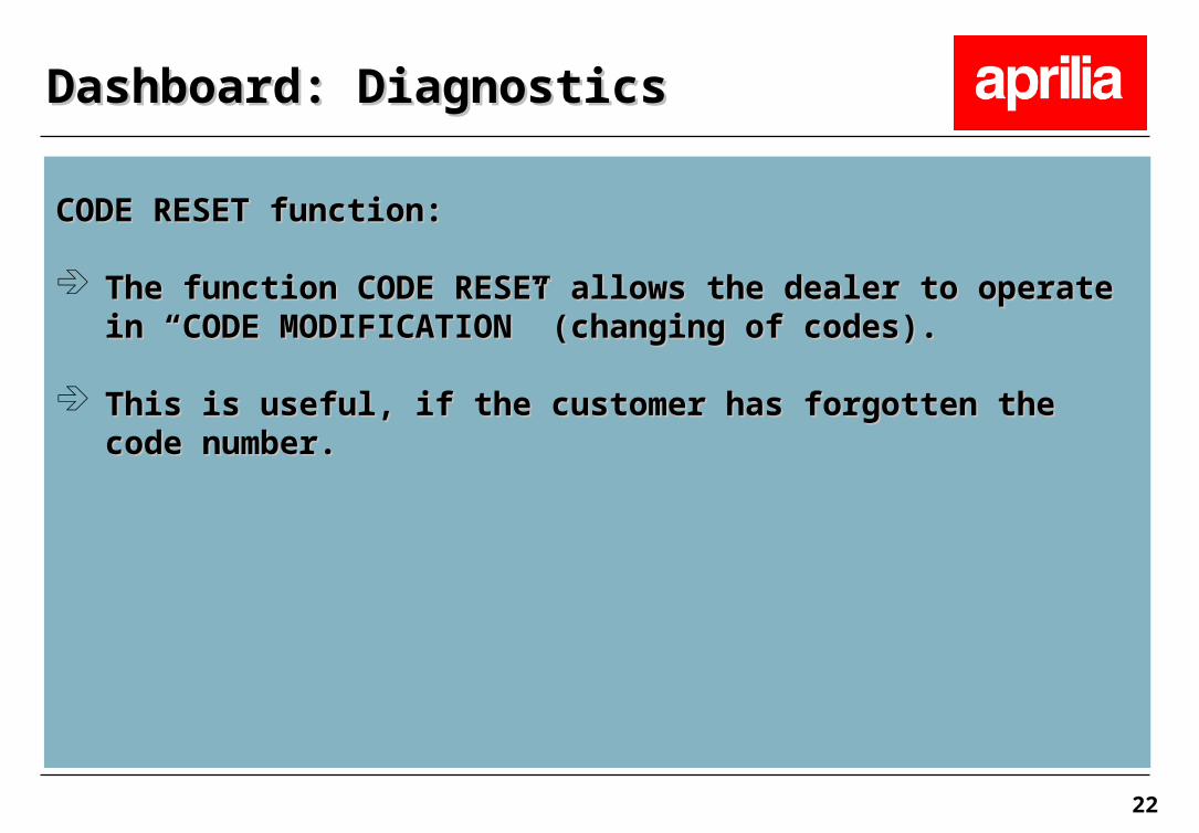
CODE RESET function: CODE RESET function:
The function CODE RESET allows the dealer to operate in “CODE The function CODE RESET allows the dealer to operate in “CODE MODIFICATION” (changing of codes).MODIFICATION” (changing of codes).
This is useful, if the customer has forgotten the code number.This is useful, if the customer has forgotten the code number.
Dashboard: DiagnosticsDashboard: Diagnostics
23
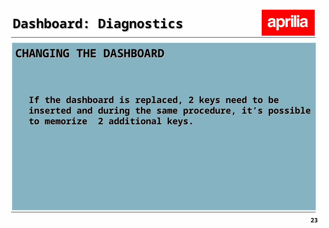
CHANGING THE DASHBOARDCHANGING THE DASHBOARD
If the dashboard is replaced, 2 keys need to be inserted and during If the dashboard is replaced, 2 keys need to be inserted and during the same procedure, it’s possible to memorize 2 additional keys.the same procedure, it’s possible to memorize 2 additional keys.
Dashboard: DiagnosticsDashboard: Diagnostics

24
In the lower part of the dashboard display the following warning In the lower part of the dashboard display the following warning lights are shown. These warning lights get switched on together lights are shown. These warning lights get switched on together with the general warning light.with the general warning light.
Coolant temperatureCoolant temperature
Oil levelOil level
Errors recognized by the dashboard or the ECUErrors recognized by the dashboard or the ECU
Dashboard: WarningsDashboard: Warnings
SERVICE

25
These errors are saved as ACT or MEM and are displayed in the These errors are saved as ACT or MEM and are displayed in the diagnosics menu. ECU errors can also be shown with the Game diagnosics menu. ECU errors can also be shown with the Game Boy.Boy.
Coolant temperature errors and oil level errors have a higher Coolant temperature errors and oil level errors have a higher priority than other errors. For example: In case of an oil level priority than other errors. For example: In case of an oil level error and an ECU error only the oil level error is displayed. error and an ECU error only the oil level error is displayed.
Dashboard: WarningsDashboard: Warnings
26
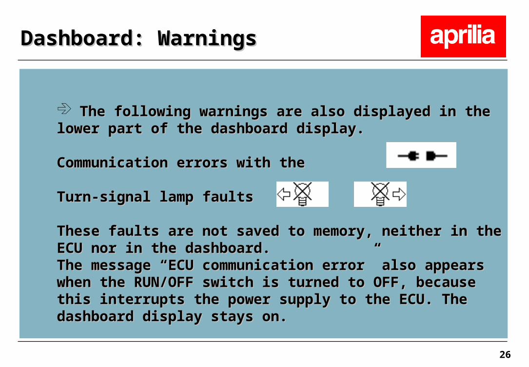
The following warnings are also displayed in the lower part of The following warnings are also displayed in the lower part of the dashboard display.the dashboard display.
Communication errors with the ECUCommunication errors with the ECU
Turn-signal lamp faultsTurn-signal lamp faults
These faults are not saved to memory, neither in the ECU nor in These faults are not saved to memory, neither in the ECU nor in the dashboard. the dashboard. The message “ECU communication error” also appears when the The message “ECU communication error” also appears when the RUN/OFF switch is turned to OFF, because this interrupts the RUN/OFF switch is turned to OFF, because this interrupts the power supply to the ECU. The dashboard display stays on.power supply to the ECU. The dashboard display stays on.
Dashboard: WarningsDashboard: Warnings
27
ECU ERROR functionECU ERROR function
The dashboard receives from the ECU regocnized errors or The dashboard receives from the ECU regocnized errors or errors from the memory.errors from the memory.
Selecting this function you can display a table of errors from Selecting this function you can display a table of errors from the ECU displaying ACT (current errors) and MEM (errors in the the ECU displaying ACT (current errors) and MEM (errors in the memory) showed with a X in the relative column as with the memory) showed with a X in the relative column as with the Game Boy.Game Boy.
The fault code and the explanation of these codes can be found The fault code and the explanation of these codes can be found in the troubleshooting table which already have been used for in the troubleshooting table which already have been used for previous versions.previous versions.
Dashboard: DiagnosticsDashboard: Diagnostics

28
Function: ERROR ECUFunction: ERROR ECU
Dashboard: DiagnosticsDashboard: Diagnostics

29
DASHBOARD ERROR functionDASHBOARD ERROR function
The dashboard provides the diagnostics for the immobilizer The dashboard provides the diagnostics for the immobilizer and the fuel level sensor.and the fuel level sensor.
With this function you can display the errors table of the With this function you can display the errors table of the dashboard with possibly errors ACT(current errors) and MEM dashboard with possibly errors ACT(current errors) and MEM (errors in the memory) showed with a X in the relative column.(errors in the memory) showed with a X in the relative column.
Even if the transponder code is incorrect or if there is a Even if the transponder code is incorrect or if there is a malfunction of the antenna, it is still possible to start the engine malfunction of the antenna, it is still possible to start the engine by entering the customer code.by entering the customer code.
Dashboard: DiagnosticsDashboard: Diagnostics

30
DASHBOARD ERROR functionDASHBOARD ERROR function
The following table shows the dashboard (DSB) fault code and The following table shows the dashboard (DSB) fault code and the description of the error.the description of the error.
Dashboard: DiagnosticsDashboard: Diagnostics
Error description Error codeImmobilizer error: Key code recordered but not recognized
DSB 01
Immobilizer error: Key code not recordered (no key or transponder defect)
DSB 02
Immobilizer error: Antenna defect or short to grownd
DSB 03
Immobilizer error: Internal error DSB 04Fuel sensor error DSB 05

31
Function: ERROR DASHBOARDFunction: ERROR DASHBOARD
Dashboard: DiagnosticsDashboard: Diagnostics
32
Immobilizer and fuel level sensor are found only from the Immobilizer and fuel level sensor are found only from the dashboard, for visualize errors it’s necessary show the dashboard, for visualize errors it’s necessary show the DASHBOARD ERRORS. All other errors are found from the ECU DASHBOARD ERRORS. All other errors are found from the ECU and shown across the ERROR ECU or with the Game Boy.and shown across the ERROR ECU or with the Game Boy.
Dashboard: DiagnosticsDashboard: Diagnostics

33
DISCONNECT functionDISCONNECT function
Dashboard and ECU are connected through the K-line. In order Dashboard and ECU are connected through the K-line. In order to connect the Game Boy, the dashboard has to be disconnected to connect the Game Boy, the dashboard has to be disconnected otherwise there could be errors when reading out the faults.otherwise there could be errors when reading out the faults.
To disconnect the dashboard, select the DISCONNECT To disconnect the dashboard, select the DISCONNECT function. The following message appears.function. The following message appears.
Dashboard disconnected. Connect Game Boy now. Dashboard disconnected. Connect Game Boy now.
Dashboard: DiagnosticsDashboard: Diagnostics

34
ERASE ERROR functionERASE ERROR function
This function will erase all errors from the dashboard and the This function will erase all errors from the dashboard and the ECU.ECU.
RESET SERVICE functionRESET SERVICE function
This function will reset the service intervall indicator, which This function will reset the service intervall indicator, which appears at 500km and then strictly at 4000 km and then every appears at 500km and then strictly at 4000 km and then every 4000 km (8.000, 12.000, 16.000, …). 4000 km (8.000, 12.000, 16.000, …). It’s possible to erase service symbol beginning from -300km in It’s possible to erase service symbol beginning from -300km in advance to the km forecasted.advance to the km forecasted.This function also allows to reset the odometer once, if 200 km This function also allows to reset the odometer once, if 200 km have not been exceeded yet. have not been exceeded yet.
Dashboard: DiagnosticsDashboard: Diagnostics
35
Km/miles functionKm/miles functionWith this function you can switch between units (km and With this function you can switch between units (km and miles).miles).
Dashboard: DiagnosticsDashboard: Diagnostics

36
REPROGRAMMING functionREPROGRAMMING function
With this function you can fixed up the dashboard for a With this function you can fixed up the dashboard for a software reprogramming with Axonesoftware reprogramming with Axone
Until now there is no new software for Axone about the Until now there is no new software for Axone about the dashboard.dashboard.
Dashboard: DiagnosticsDashboard: Diagnostics

37
A new map is available for this new version 2005 with the Game A new map is available for this new version 2005 with the Game Boy cartridgeBoy cartridge
2.8.02.8.0
Warning: if you make connection with Axone,you cannot go to the Warning: if you make connection with Axone,you cannot go to the test map for dealer because it corresponds to the old Game Boy test map for dealer because it corresponds to the old Game Boy version 2.5.0. version 2.5.0.
All the other functions are available: engine parameter, control All the other functions are available: engine parameter, control device, error display, etc..device, error display, etc..
Updates on injection systemUpdates on injection system

38
Connecting with diagnostic instruments, you’ll always found Connecting with diagnostic instruments, you’ll always found a NOT real error due to the not connection between the ECU a NOT real error due to the not connection between the ECU and the alalrm lamp (because of only K line exist on this and the alalrm lamp (because of only K line exist on this vehicle):vehicle):with Game Boy shows error: with Game Boy shows error: “EFI WARNING LIGHT”“EFI WARNING LIGHT”with Axone shows error:with Axone shows error: ““CHECK ENGINE WARNING CHECK ENGINE WARNING
LIGHTLIGHT””
They are errors not to be considered importantThey are errors not to be considered importantThis error is not showed I n the dashboardThis error is not showed I n the dashboard
Updates on injection systemUpdates on injection system
39
C361M: Ambient air pressure sensor now inside the ECU ( till now C361M: Ambient air pressure sensor now inside the ECU ( till now external)external)
Wiring diagram of Ditech and C361M now also show connections Wiring diagram of Ditech and C361M now also show connections with K-linewith K-line
Updates on injection systemUpdates on injection system

40
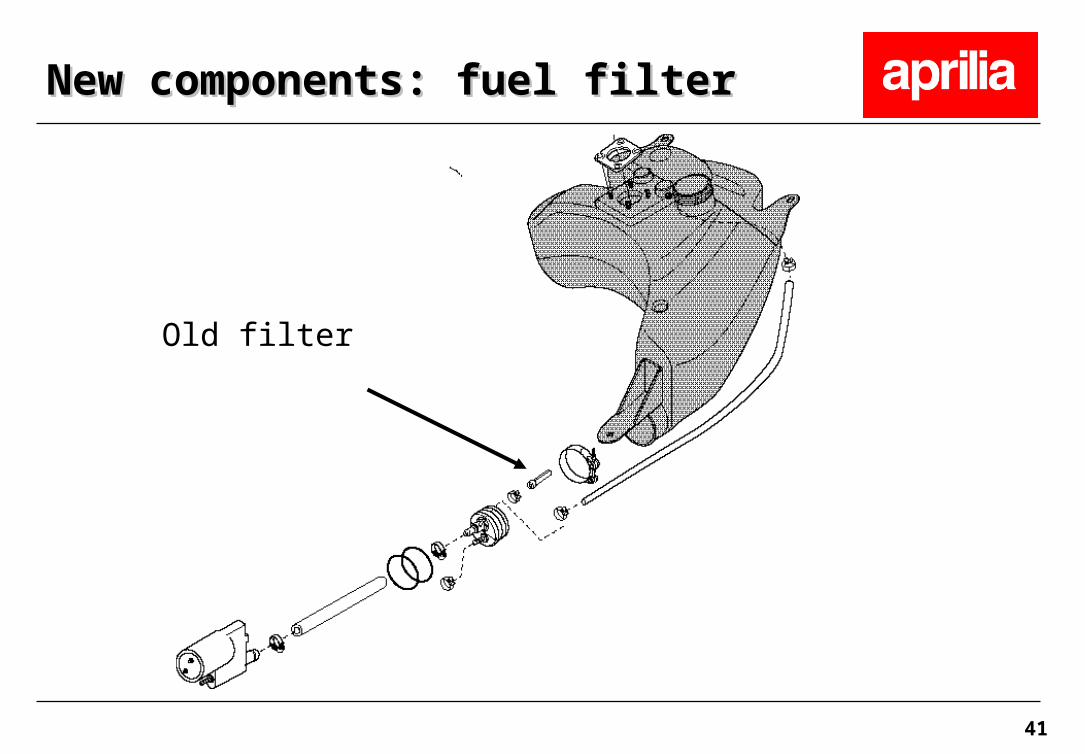
Since July 2004 all new vehicles are equipped with an external fuel Since July 2004 all new vehicles are equipped with an external fuel filter (until then the fuel filter was located inside the tank) which is filter (until then the fuel filter was located inside the tank) which is more effective.more effective.
New components: fuel filterNew components: fuel filter
41
Old filter
New components: fuel filterNew components: fuel filter

42
New filter
New components: fuel filterNew components: fuel filter

43
New components: fuel filterNew components: fuel filter

44
New components: fuel filterNew components: fuel filter

45
It is possible to install the “Filter Kit”, code It is possible to install the “Filter Kit”, code 82024368202436 on the on the vehicles with the old filter: in case of pump substitution it’s vehicles with the old filter: in case of pump substitution it’s necessary to install the KIT, in order to prevent continuous necessary to install the KIT, in order to prevent continuous damage to the pump .damage to the pump .
Take the old filter out of the fuel tank, and connect the ventilation Take the old filter out of the fuel tank, and connect the ventilation tube to the new filter, not to the old ring that must be removed.tube to the new filter, not to the old ring that must be removed.
Please note: When you order the old filter or the ring, the new Please note: When you order the old filter or the ring, the new “Filter Kit” is sent automatically.“Filter Kit” is sent automatically.
New components: fuel filterNew components: fuel filter

46
New components: fuel filterNew components: fuel filter

47
Ditech engines are equipped with quick fit connectors (since Ditech engines are equipped with quick fit connectors (since C361M).C361M).
Kit pressure gauge fuel code 8140488
New Ditech engines are equipped with quick fit connectors. For connection of an old manometer to the new quick fit connectors, use code 8140730
New components: quick fit connectorsNew components: quick fit connectors
48
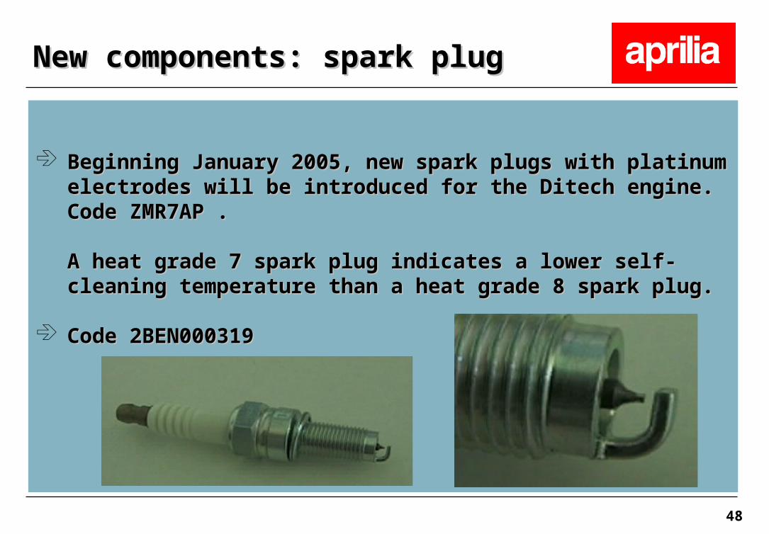
Beginning January 2005, new spark plugs with platinum electrodes Beginning January 2005, new spark plugs with platinum electrodes will be introduced for the Ditech engine. Code ZMR7AP .will be introduced for the Ditech engine. Code ZMR7AP .
A heat grade 7 spark plug indicates a lower self-cleaning A heat grade 7 spark plug indicates a lower self-cleaning temperature than a heat grade 8 spark plug.temperature than a heat grade 8 spark plug.
Code 2BEN000319Code 2BEN000319
New components: spark plugNew components: spark plug
49
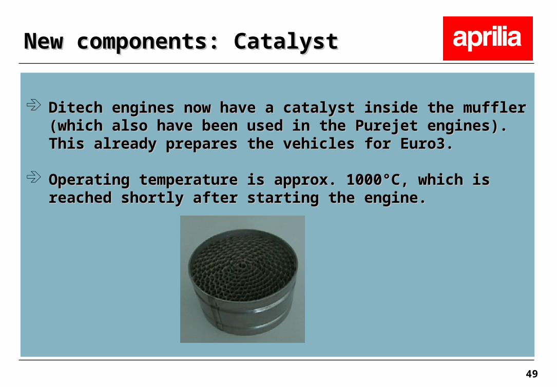
Ditech engines now have a catalyst inside the muffler (which also Ditech engines now have a catalyst inside the muffler (which also have been used in the Purejet engines). This already prepares the have been used in the Purejet engines). This already prepares the vehicles for Euro3.vehicles for Euro3.
Operating temperature is approx. 1000°C, which is reached shortly Operating temperature is approx. 1000°C, which is reached shortly after starting the engine.after starting the engine.
New components: CatalystNew components: Catalyst
50
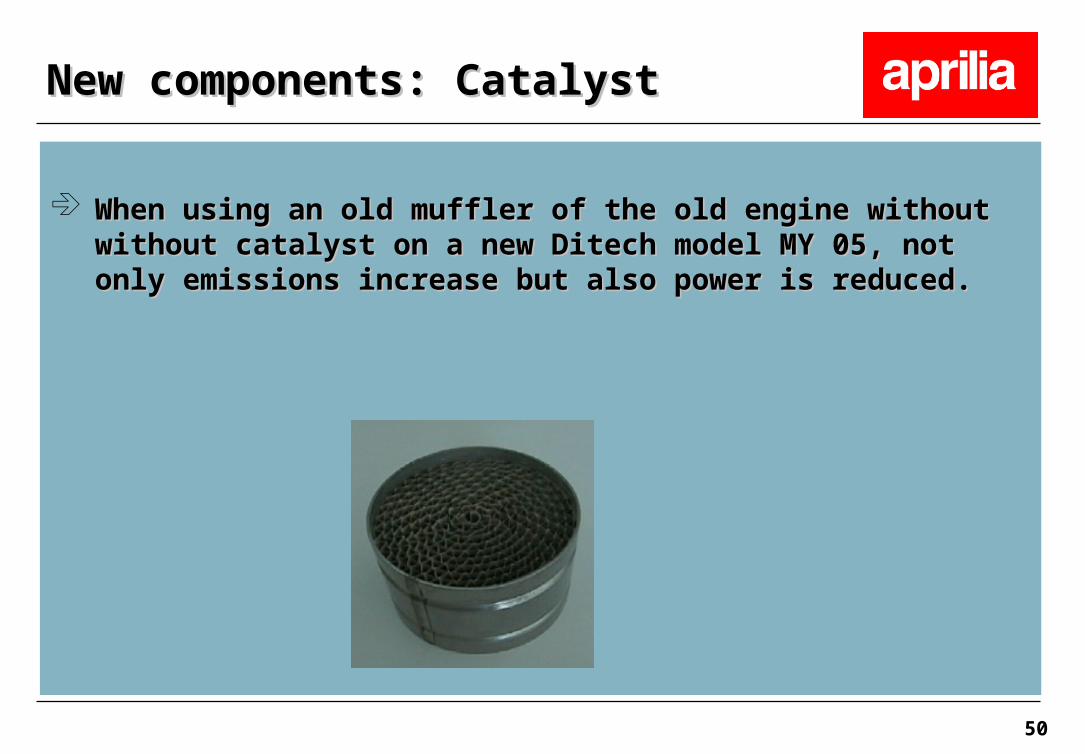
When using an old muffler of the old engine without without When using an old muffler of the old engine without without catalyst on a new Ditech model MY 05, not only emissions increase catalyst on a new Ditech model MY 05, not only emissions increase but also power is reduced.but also power is reduced.
New components: CatalystNew components: Catalyst

51
Together with the introduction of the muffler with catalyst, which Together with the introduction of the muffler with catalyst, which influences the engine power, for the Ditech 45km/h also variator influences the engine power, for the Ditech 45km/h also variator rollers of 6.8g (7.7g for older models) have been introduced. rollers of 6.8g (7.7g for older models) have been introduced.
New components: variator rollerNew components: variator roller

52
To reduce starting problems, a new battery with 9A/h has replaced To reduce starting problems, a new battery with 9A/h has replaced the old MF batteries with 4A/h. the old MF batteries with 4A/h.
New components: BatteryNew components: Battery

53