Embed Size (px)
Citation preview
Decision D-2018-145 Effective: January 1, 2019
Technical Requirements for the
Connection of Customer Facilities to the Hydro-Québec
Transmission System

Technical Requirements for the Connection of Customer Facilities to the Hydro-Québec Transmission System 3
Decision D-2018-145 Effective: January 1, 2019
Table of Contents
1 Purpose .......................................................................................................................................................... 5
2 Application ..................................................................................................................................................... 5
3 Definitions ...................................................................................................................................................... 5
4 Procedure and technical information required ........................................................................................... 6
5 Technical requirements applicable to customer substation equipment ................................................. 10
5.1 Customer substation ........................................................................................................................... 10
5.2 Transmission System grounding connection ....................................................................................... 11 5.2.1 Effectively grounded Transmission System ..................................................................................... 11 5.2.2 Non-effectively grounded Transmission System.............................................................................. 12
5.3 General electrical characteristics of equipment ................................................................................... 12
5.4 Disconnect switch ............................................................................................................................... 13
5.5 Tie breaker .......................................................................................................................................... 14
5.6 Surge arrester ..................................................................................................................................... 14
5.7 Power transformer ............................................................................................................................... 14
6 Technical requirements applicable to customer facility protection systems ......................................... 15
6.1 Circuit breaker protection .................................................................................................................... 15
6.2 Fuse protection ................................................................................................................................... 15
6.3 Performance of customer facility protection systems .......................................................................... 15 6.3.1 Protection against customer facility faults ........................................................................................ 15 6.3.2 Protection against Transmission System faults ............................................................................... 16 6.3.3 Special protection measures ........................................................................................................... 17
6.4 Design of customer facility protection systems ................................................................................... 17
6.5 Telecommunication systems ............................................................................................................... 18
7 Requirements regarding customer substation equipment maintenance ............................................... 19
8 Requirements regarding customer substation equipment operation ..................................................... 19
9 Special technical requirements .................................................................................................................. 19
9.1 Declared power of 900 MW or more ................................................................................................... 19
9.2 Bulk Power System ............................................................................................................................. 19
9.3 Event recorders ................................................................................................................................... 20
9.4 Future system voltage changes on the Transmission System ............................................................ 20
9.5 Construction of transmission line ........................................................................................................ 20
Appendix A Technical data to be provided with a connection request .................................................... 21
Appendix B Customer facility protection study .......................................................................................... 26
Appendix C Data required for Transmission System operation ................................................................ 28
Technical Requirements for the Connection of Customer Facilities to the Hydro-Québec Transmission System 4
Decision D-2018-145 Effective: January 1, 2019
List of Tables
Table 1 Technical information required .............................................................................................................. 8
Table 2 Standard insulation and short-circuit levels for Transmission System equipment ................................13
List of Figures
Figure 1 Equipment on the high-voltage side of the customer substation .......................................................... 10
Figure 2 Customer substation telecommunication system ................................................................................ 18
Technical Requirements for the Connection of Customer Facilities to the Hydro-Québec Transmission System 5
Decision D-2018-145 Effective: January 1, 2019
1 Purpose
This document sets out technical requirements for the connection of customer facilities1 to
the Hydro-Québec Transmission System.
Compliance with technical requirements is required to ensure:
Reliability of the Hydro-Québec Transmission System
Stability of the Transmission System and of the facilities connected to it
Maintaining service quality for customers connected to the Hydro-Québec
Transmission System
Protection of Transmission Provider equipment
Human safety
2 Application
This document applies to any customer facility to be connected to the Hydro-Québec
Transmission System and any facility connected to it undergoing modifications, including the
recommissioning of a facility that has been completely or partially shut down.
The connection of a generating station to the Transmission System through a customer
facility is subject to the relevant provisions of Technical Requirements for the Connection of
Generating Stations to the Hydro-Québec Transmission System2.
3 Definitions
Italicized terms in the text are defined below.
Available power
Defined in Section 21.1 of the Conditions of Electricity Service, as approved from time to
time by the Régie de l'énergie.
Bulk Power System
The Bulk Power System as defined in the Glossary of Terms and Acronyms used in
Reliability Standards and its modifications as adopted from time to time by the Régie
de l’énergie.
Conditions of Electricity Service
The conditions governing electricity service set out by the Distributor, as approved from time
to time by the Régie de l'énergie.
1 The term facilities refers to electrical installations as defined in the Conditions of Electricity Service, as
approved from time to time by the Régie de l'énergie. 2 As approved from time to time by the Régie de l'énergie.
Technical Requirements for the Connection of Customer Facilities to the Hydro-Québec Transmission System 6
Decision D-2018-145 Effective: January 1, 2019
Customer
Defined in Section 21.1 of the Conditions of Electricity Service, as approved from time to
time by the Régie de l'énergie.
Customer substation
Defined in Section 21.1 of the Conditions of Electricity Service, as approved from time to
time by the Régie de l'énergie.
Distributor
Hydro-Québec when carrying on electric power distribution activities.
Hydro-Québec Open Access Transmission Tariff
Document setting out the rates and conditions whereby the Transmission Provider transmits
electricity in Québec, as approved from time to time by the Régie de l'énergie.
Metering equipment
Defined in Section 21.1 of the Conditions of Electricity Service, as approved from time to
time by the Régie de l'énergie.
Technical requirement
Defined in Section 21.1 of the Conditions of Electricity Service, as approved from time to
time by the Régie de l'énergie.
Transmission Provider
Hydro-Québec when carrying on electric power transmission activities.
Transmission System
Defined in Section 1.49 of the Hydro-Québec Open Access Transmission Tariff, as
approved from time to time by the Régie de l'énergie.
Voltage
Defined in Section 21.1 of the Conditions of Electricity Service, as approved from time to
time by the Régie de l'énergie.
Medium voltage: nominal phase-to-phase voltage of more than 750 V, but less than
44,000 V
High voltage: nominal phase-to-phase voltage of 44,000 V or more
4 Procedure and technical information required
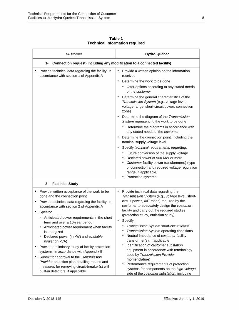
Table 1 summarizes the procedure and technical information required from the customer
and Hydro-Québec further to a request for the connection of any customer facility to the
Technical Requirements for the Connection of Customer Facilities to the Hydro-Québec Transmission System 7
Decision D-2018-145 Effective: January 1, 2019
Transmission System or in the advent of any modification to an already connected customer
facility.
Technical information required to evaluate compliance with emission limits is specified in
Appendix A of Emission Limits for Disturbances on the Hydro-Québec Transmission
System3.
3 As approved from time to time by the Régie de l'énergie.
Technical Requirements for the Connection of Customer Facilities to the Hydro-Québec Transmission System 8
Decision D-2018-145 Effective: January 1, 2019
Table 1
Technical information required
Customer Hydro-Québec
1- Connection request (including any modification to a connected facility)
• Provide technical data regarding the facility, in
accordance with section 1 of Appendix A
• Provide a written opinion on the information
received
• Determine the work to be done
Offer options according to any stated needs
of the customer
• Determine the general characteristics of the
Transmission System (e.g., voltage level,
voltage range, short-circuit power, connection
zone)
• Determine the diagram of the Transmission
System representing the work to be done
Determine the diagrams in accordance with
any stated needs of the customer
• Determine the connection point, including the
nominal supply voltage level
• Specify technical requirements regarding:
Future conversion of the supply voltage
Declared power of 900 MW or more
Customer facility power transformer(s) (type
of connection and required voltage regulation
range, if applicable)
Protection systems
2- Facilities Study
• Provide written acceptance of the work to be
done and the connection point
• Provide technical data regarding the facility, in
accordance with section 2 of Appendix A
• Specify:
Anticipated power requirements in the short
term and over a 10-year period
Anticipated power requirement when facility
is energized
Declared power (in kW) and available
power (in kVA)
• Provide preliminary study of facility protection
systems, in accordance with Appendix B
• Submit for approval to the Transmission
Provider an action plan detailing means and
measures for removing circuit-breaker(s) with
built-in detectors, if applicable
• Provide technical data regarding the
Transmission System (e.g., voltage level, short-
circuit power, X/R ratios) required by the
customer to adequately design the customer
facility and carry out the required studies
(protection study, emission study)
• Specify:
Transmission System short-circuit levels
Transmission System operating conditions
Neutral impedance of customer facility
transformer(s), if applicable
Identification of customer substation
equipment in accordance with terminology
used by Transmission Provider
(nomenclature)
Performance requirements of protection
systems for components on the high-voltage
side of the customer substation, including
Technical Requirements for the Connection of Customer Facilities to the Hydro-Québec Transmission System 9
Decision D-2018-145 Effective: January 1, 2019
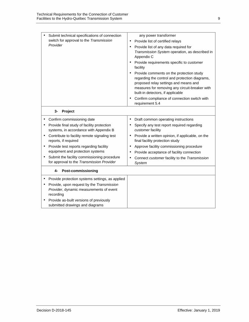
• Submit technical specifications of connection
switch for approval to the Transmission
Provider
any power transformer
• Provide list of certified relays
• Provide list of any data required for
Transmission System operation, as described in
Appendix C
• Provide requirements specific to customer
facility
• Provide comments on the protection study
regarding the control and protection diagrams,
proposed relay settings and means and
measures for removing any circuit-breaker with
built-in detectors, if applicable
• Confirm compliance of connection switch with
requirement 5.4
3- Project
• Confirm commissioning date
• Provide final study of facility protection
systems, in accordance with Appendix B
• Contribute to facility remote signaling test
reports, if required
• Provide test reports regarding facility
equipment and protection systems
• Submit the facility commissioning procedure
for approval to the Transmission Provider
• Draft common operating instructions
• Specify any test report required regarding
customer facility
• Provide a written opinion, if applicable, on the
final facility protection study
• Approve facility commissioning procedure
• Provide acceptance of facility connection
• Connect customer facility to the Transmission
System
4- Post-commissioning
• Provide protection systems settings, as applied
• Provide, upon request by the Transmission
Provider, dynamic measurements of event
recording
• Provide as-built versions of previously
submitted drawings and diagrams
Technical Requirements for the Connection of Customer Facilities to the Hydro-Québec Transmission System 10
Decision D-2018-145 Effective: January 1, 2019
5 Technical requirements applicable to customer substation equipment
5.1 Customer substation
The customer facility comprises the high-voltage customer substation and the medium-
voltage customer equipment. The customer substation comprises high-voltage equipment,
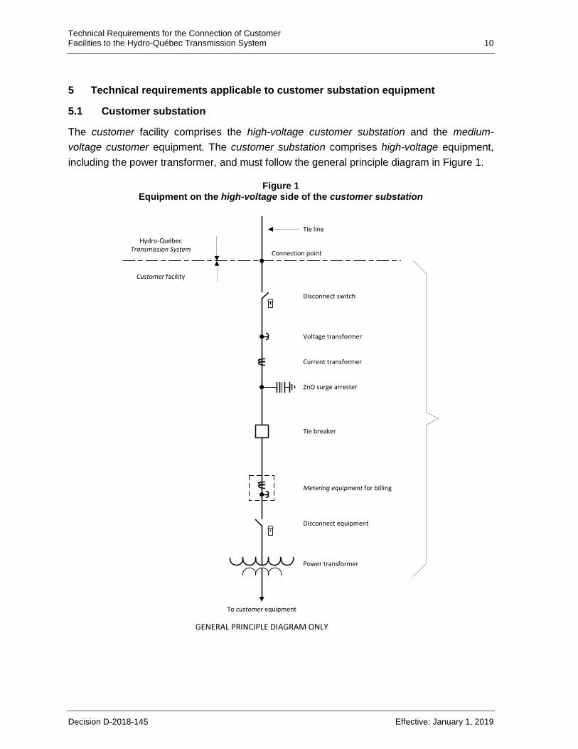
including the power transformer, and must follow the general principle diagram in Figure 1.
Figure 1 Equipment on the high-voltage side of the customer substation
Hydro-Québec Transmission System
Connection point
ZnO surge arrester
Current transformer
Voltage transformer
Disconnect switch
Tie breaker
Metering equipment for billing
Disconnect equipment
Power transformer
To customer equipment
GENERAL PRINCIPLE DIAGRAM ONLY
Tie line
Customer facility
Technical Requirements for the Connection of Customer Facilities to the Hydro-Québec Transmission System 11
Decision D-2018-145 Effective: January 1, 2019
The connection point is located between the Hydro-Québec Transmission System (usually a
high-voltage line) and the customer facility. The point is generally located at the dead-end
insulators in the customer substation, near the disconnect switch or at any other place
agreed to, in writing, by Hydro-Québec and the customer.
The disconnect switch is the first visible disconnection point in the customer facility; it must
be located as close as possible to the connection point. It must be possible to lock out the
disconnect switch in the open position.
The tie breaker (i.e. the circuit breaker on the high-voltage side of the customer substation)
must be located as close as possible to the disconnect switch.
The current transformer must be located between the connection switch and the tie breaker.
A voltage transformer may be required; it may be located on either side of the tie breaker if
the customer substation is supplied over a single circuit or several circuits not normally
operated in parallel. The voltage transformer must be located on the line side of the tie
breaker if the customer substation is supplied over several circuits normally operated
in parallel.
If the customer wishes to install a surge arrester, it must be installed on each of the three
phases, on the customer substation side of the disconnect switch.
The metering equipment for billing must be located between the tie breaker and the power
transformer of the customer substation, unless another location is agreed to in writing by the
customer and Hydro-Québec. A visible disconnection point (e.g., a disconnect switch) must
be located between the metering equipment and the customer equipment. If it is a
disconnect switch, it must be possible to lock it out in the open position.
5.2 Transmission System grounding connection
The customer facility must be designed to be compatible at all times with the characteristics
of the Transmission System grounding connection.
5.2.1 Effectively grounded Transmission System
Most facilities on the Transmission System are effectively grounded, i.e., meet the following
criteria:
0 ≤ X0/X1 ≤ 3 and 0 ≤ R0/X1 ≤ 1
Where:
X1 = positive-sequence reactance of system
X0 = zero-sequence reactance of system
R0 = zero-sequence resistance of system
Technical Requirements for the Connection of Customer Facilities to the Hydro-Québec Transmission System 12
Decision D-2018-145 Effective: January 1, 2019
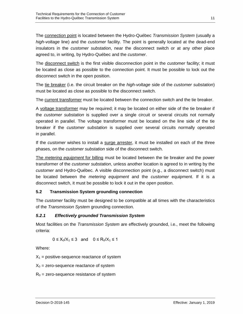
The customer substation must be effectively grounded on the high-voltage side and has to
meet the following criteria:
0 ≤ (X0)i/(X1)i ≤ 3 and 0 ≤ (R0)i/(X1)i ≤ 1
Where:
(X1)i = positive-sequence reactance of customer facility seen from high-voltage side of
customer substation
(X0)i = zero-sequence reactance of customer facility seen from high-voltage side of customer
substation
(R0)i = zero-sequence resistance of customer facility seen from high-voltage side of
customer substation
To meet these criteria, the customer must:
• add grounding transformer(s) on the high-voltage side of the customer substation;
or
• ground the neutral on the high-voltage winding side of the power transformer(s) of
the customer substation, i.e. choose the YNd or YNynd winding connection type or
modify the winding connection type accordingly.
In the case of an existing facility, the Transmission Provider determines whether an
alternate requirement may apply.
5.2.2 Non-effectively grounded Transmission System
In parts of the 69 kV or lower Transmission System, the neutral is not effectively grounded.
The zero-sequence impedance is then higher than for an effectively-grounded Transmission
System.
The customer facility must be designed to avoid contributing more than 400 A to the single-
phase fault current on the part of the Transmission System which is not effectively
grounded, unless otherwise agreed to by the Transmission Provider.
A grounding transformer of appropriate impedance is generally required on the high-voltage
side of the customer substation to keep the zero-sequence impedance from becoming
capacitive due, for instance, to the capacitive effect of lines or cables on the Transmission
System side, and causing significant overvoltages.
5.3 General electrical characteristics of equipment
The general electrical characteristics of equipment forming the customer facility must be
compatible with those of the Transmission System to which this facility is connected, in
particular regarding equipment insulation coordination.
Technical Requirements for the Connection of Customer Facilities to the Hydro-Québec Transmission System 13
Decision D-2018-145 Effective: January 1, 2019
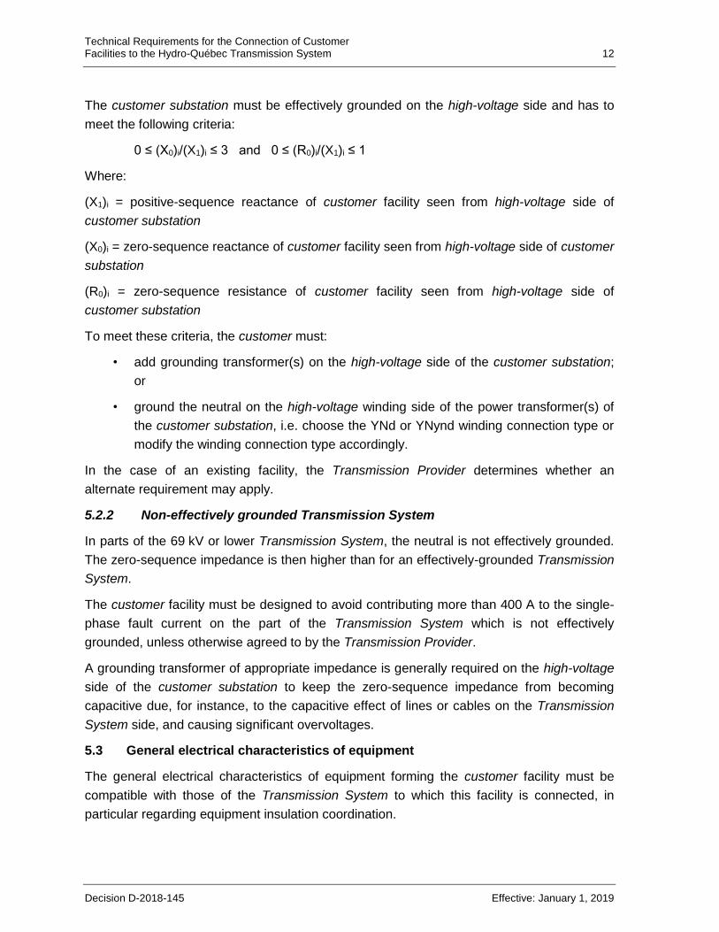
Table 2 presents standard insulation and short-circuit levels for Transmission System
equipment according to nominal Transmission System voltage.
Table 2
Standard insulation and short-circuit levels for Transmission System equipment
Nominal system
voltage 1
(kV L-L rms)
Rated voltage of
equipment
(kV L-L rms)
Ground insulation level 2 Standard short-
circuit levels 3
(kA sym. rms) Lightning
(kV peak)
60 Hz
(kV rms)
69 72,5 350 140 31,5
120 145 550 230 40
161 170 650-750 4 275-325 4 31.5 and 50 5
230 245 850-950 4 360-395 4 31.5 and 50 5
315 330 1 050-1 175 4 460 31.5 and 50 5
1 Insulation and short-circuit levels have not been standardized for 44-kV, 49.2-kV, 345-kV and 735-kV voltage levels and must be confirmed by the Transmission Provider on a case-by-case basis.
2 Insulation level between open contacts of disconnect switches must be higher than the ground insulation level. This requirement also applies to 330-kV circuit breakers.
3 The X/R ratio used for these voltage levels is equivalent to 30. 4 The lower value applies to transformers and shunt reactors protected by surge arresters at their
terminals; the higher value applies broadly to all other equipment. 5 The short-circuit level depends on the specific characteristics of the Transmission System to which
the customer substation is connected. 6 The switching impulse withstand voltage is 850 kV peak.
5.4 Disconnect switch
To ensure the safety of all personnel during work on the Transmission System, each supply
circuit of the customer substation must be equipped with a disconnect switch. In some
cases, the Transmission Provider may allow some device other than a disconnect switch
(e.g., plug-in circuit breaker) to act as a disconnection point.
The disconnect switch must provide a visible disconnection point in the customer facility and
be accessible to the Transmission Provider.
It is used to isolate the customer facility from the Transmission System. It must be possible
to lock out the disconnect switch in the open position (blades opening upwards forming an
angle greater than 90°).
For motorized disconnect switches, it must be possible to disable, uncouple and lock out the
control and drive mechanism. A device for cutting power to the motor (e.g., using a knife-
switch) and a place for installing a padlock on the control box door must be provided. The
control tube must also include a locking device equipped with a pin.
Technical Requirements for the Connection of Customer Facilities to the Hydro-Québec Transmission System 14
Decision D-2018-145 Effective: January 1, 2019
Furthermore, if the emergency mechanism is a wheel, it must be possible to lock out the
external selection switch and the knife-switches must be visible through a window when the
control box is closed and locked out.
If the emergency mechanism is crank-operated, the knife-switches and local control selector
switch must be visible through a window when the control box is locked out.
Openings for padlocks or locking clamps must have a diameter of 12 mm.
In no instance may a disconnect switch be coupled to a grounding switch on the
Transmission System side; such a configuration would automatically ground the connection
point when the disconnect switch opens.
5.5 Tie breaker
The tie breaker, which is usually required, must interrupt any fault current within the
customer facility or on any part of the Transmission System to which this facility
is connected.
It must be possible for tie breakers to perform an O-C-O (open-close-open) cycle for eight
consecutive hours with no power from the grid.
If a tie breaker has a built-in system for detecting faulty internal states (e.g., low SF6 density)
that can force it to close or prevent it from operating normally (e.g., latching in open or
closed position), the customer must, when a faulty state is detected, remove the breaker in
question from operation as quickly as possible to avoid damage to its facility or undue
disturbances on the Transmission System.
5.6 Surge arrester
If the customer wishes to install a surge arrester, it must be of the zinc oxide type with no
spark gap when it is located on the high-voltage side of the customer substation. The surge
arrester must be sized according to Transmission System constraints.
5.7 Power transformer
The customer must provide appropriate regulation equipment in the customer substation,
taking into account potential steady-state voltage variations4 in the Transmission System.
The customer is advised to equip power transformers with on-load tap changers and
automatic voltage regulation systems in order to be able to adjust the transformer ratio
according to Transmission System voltage and load conditions.
4 Voltage ranges are provided in Caractéristiques de la tension fournie par le réseau de transport
d’Hydro-Québec, a reference provided only for explanatory and informative purposes.
Technical Requirements for the Connection of Customer Facilities to the Hydro-Québec Transmission System 15
Decision D-2018-145 Effective: January 1, 2019
The impedance and connections of power transformer windings must always be compatible
with the characteristics of the Transmission System grounding connection.
Depending on the characteristics of the Transmission System near the connection point, it
may also be necessary to add a reactor on the high-voltage side of the customer substation,
between the neutral of each power transformer and ground, to limit the contribution of the
customer facility to zero-sequence current during Transmission System faults.
6 Technical requirements applicable to customer facility protection systems
The customer must provide protection systems to protect equipment within its facility against
any fault or abnormal operating condition occurring either within its facility or on the
Transmission System. These protection systems include equipment such as protective
relays, panels, junction boxes, cabling, current and voltage transformers and remote
protection systems (remote tripping or remote blocking), when required.
Coordination of customer facility protection systems must comply with section 15.2.7 of
Conditions of Electricity Service.
6.1 Circuit breaker protection
The customer facility must be equipped with at least one circuit breaker on the high-voltage
side of the customer substation to adequately clear faults.
6.2 Fuse protection
If the customer facility is connected over a single circuit to a portion of the Transmission
System operating at 69 kV or less, a fuse-based protection system may be used in the
customer substation to protect the customer facility subject to prior approval by the
Transmission Provider. Fuse protection of the customer facility must be coordinated with
Transmission System protections; the ratio of short-circuit current to fuse rating, at the
connection point, must be at least 100.
6.3 Performance of customer facility protection systems
6.3.1 Protection against customer facility faults
The customer substation must be equipped with protection systems that can quickly and
reliably detect and clear any type of fault within the customer facility. Such systems must be
compatible and coordinated with those used at the substation serving the customer
substation. The customer must select protective relays that ensure secure and selective
coverage for its equipment.
Protection systems for customer substation equipment must comply with the performance
requirements set out by the Transmission Provider, in particular the maximum fault-clearing
Technical Requirements for the Connection of Customer Facilities to the Hydro-Québec Transmission System 16
Decision D-2018-145 Effective: January 1, 2019
time, and the number of protective functions required to ensure adequate coverage of the
equipment in question.
6.3.2 Protection against Transmission System faults
If the customer substation is supplied over a single circuit or several circuits not normally
operated in parallel, it is generally unnecessary to install protection systems to detect faults
on the Transmission System.
If the customer substation is supplied by circuits normally operated in parallel, the following
requirements apply.
The customer substation must be equipped with protection systems that detect
Transmission System faults. The contribution of the customer facility to such faults must be
cleared using a circuit breaker. The design of such protection systems varies according to
the characteristics of the Transmission System to which the customer facility is connected.
They must quickly, reliably, selectively and safely clear the contribution to the fault carried
on the Transmission System through the customer facility.
At 69 kV or higher, customer facility protection systems must comprise two primary
protections. Each one of these primary protections uses a separate protective relay, as well
as a trip relay. Such protections must have the following characteristics:
• The primary protection must cover all types of faults (three-phase, two-phase, two-
phase-to-ground, and phase-to-ground with and without a fault impedance). For
high-impedance faults5, the fault resistance used must be Rf = 10 Ω, i.e., a zero-
sequence component of 3Rf = 30 Ω.
• The primary protection must operate as soon as the fault is detected, without delay,
and comply with the Transmission System speed requirements.
• The primary protection must be selective and coordinated with protections in
adjacent zones.
It is recommended that these protection systems differ in design or in manufacturer. Such
protection systems may require telecommunication links.
Breaker failure protection
Breaker failure protection is required at the customer substation in the following
circumstances:
5 Type of insulation fault where the fault resistance is sufficiently high to maintain a significant voltage at the
fault location between the conductor and the ground, or between the conductors.
Technical Requirements for the Connection of Customer Facilities to the Hydro-Québec Transmission System 17
Decision D-2018-145 Effective: January 1, 2019
• If the customer substation is supplied over several circuits normally operated in
parallel, breaker failure protection is required to enable tripping of circuit breakers in
adjacent zones when a circuit breaker refuses to trip.
• When rapid circuit breaker tripping is needed to meet Transmission System
requirements, breaker failure protection is required to ensure remote tripping of
circuit breakers at the substations serving the customer substation.
Reclosing of circuit breakers by line protections
If the customer substation is supplied by circuits normally operated in parallel and equipped
with line protections, automatic reclosing of high-voltage circuit breakers in that substation is
prohibited.
6.3.3 Special protection measures
Islanding of motor loads on other neighboring substations
In some cases, protections may be required to prevent islanding of motor loads on
neighboring substations (another customer substation or a Transmission System substation)
according to the characteristics of the motor load on the customer facility and Transmission
System to which it is connected.
Remote tripping
Remote tripping6 of the customer substation is required in either of the cases below.
• The reclosing time of the line is less than 2 seconds and the customer facility has a
motor load that is sensitive to rapid reclosing.
• There is a risk of self-excitation when islanding of a motor load is possible in the
customer facility with a capacitive load (e.g., capacitor bank, filter, unloaded line or
cable).
6.4 Design of customer facility protection systems
Protection against Transmission System faults
When protection systems are required in the customer substation to detect abnormal
conditions on the Transmission System, they must comply with the requirements below.
• Protective and trip relays must be certified7 by the Transmission Provider.
• Protection systems must be powered using storage batteries, since they must
remain functional during an auxiliary power supply failure. Each storage battery
6 The remotely controlled opening of a circuit breaker by an automatic control or protection system. 7 Certified relays are relays that the Transmission Provider has approved for use following validation testing.
Technical Requirements for the Connection of Customer Facilities to the Hydro-Québec Transmission System 18
Decision D-2018-145 Effective: January 1, 2019
must have two chargers that can either run in parallel with the battery or back up
each other. Battery autonomy must be at least eight consecutive hours.
• Current and voltage transformers must be installed on each of the three phases to
power protection system relays. The transformers must have separate secondary
windings in order to power separately the relays of the two primary protection
systems.
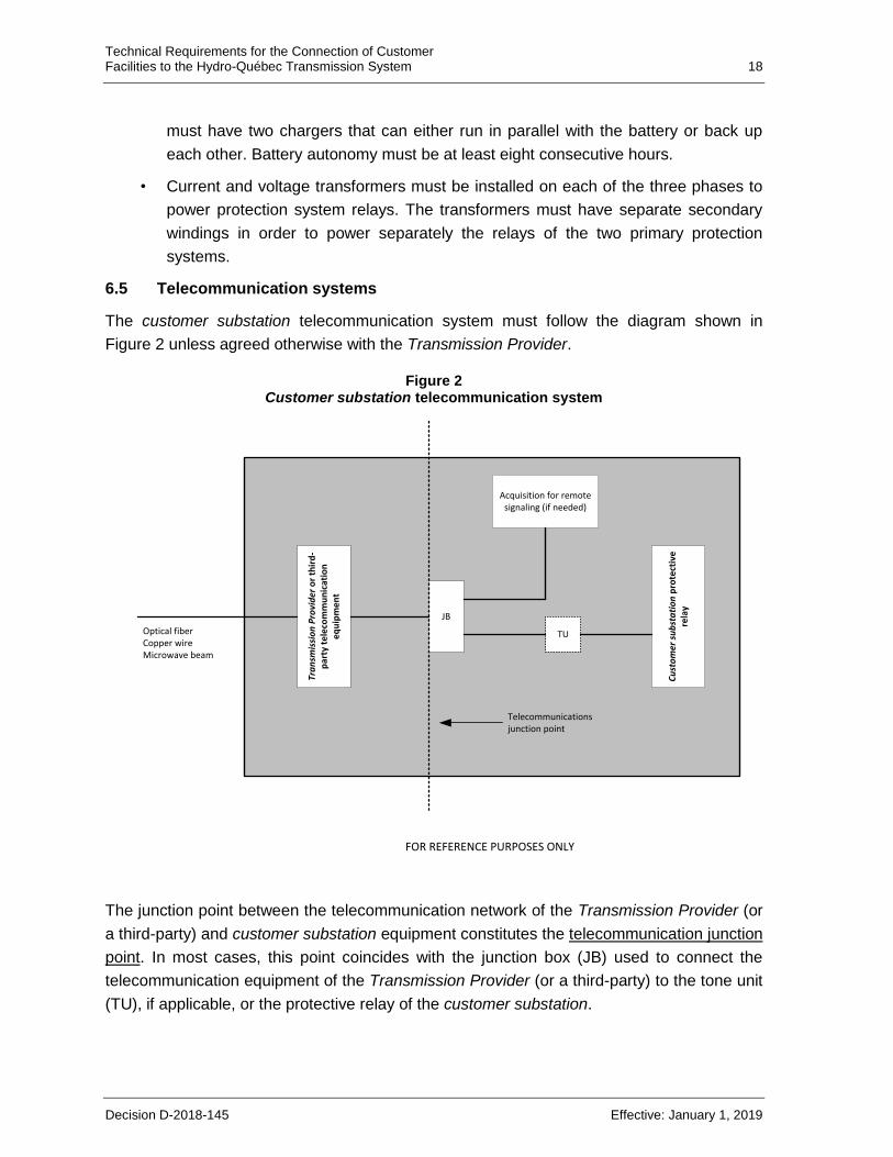
6.5 Telecommunication systems
The customer substation telecommunication system must follow the diagram shown in
Figure 2 unless agreed otherwise with the Transmission Provider.
Figure 2 Customer substation telecommunication system
Tra
nsm
issi
on
Pro
vid
er o
r th
ird
-p
arty
te
leco
mm
un
icat
ion
e
qu
ipm
en
t
JB
Acquisition for remote signaling (if needed)
Cu
sto
mer
su
bst
ati
on
pro
tect
ive
re
lay
Telecommunications junction point
TUOptical fiberCopper wireMicrowave beam
FOR REFERENCE PURPOSES ONLY
The junction point between the telecommunication network of the Transmission Provider (or
a third-party) and customer substation equipment constitutes the telecommunication junction
point. In most cases, this point coincides with the junction box (JB) used to connect the
telecommunication equipment of the Transmission Provider (or a third-party) to the tone unit
(TU), if applicable, or the protective relay of the customer substation.
Technical Requirements for the Connection of Customer Facilities to the Hydro-Québec Transmission System 19
Decision D-2018-145 Effective: January 1, 2019
The customer must supply electricity, as well as adequate secure space for installing all this
equipment; the customer must also install all required ductwork, junction boxes, as well as
tone or remote protection units that are part of the protection systems.
7 Requirements regarding customer substation equipment maintenance
The customer must plan the maintenance of its equipment, in particular all equipment
located between the connection point and the tie breaker (high-voltage side) inclusively, on
an annual basis and coordinate its maintenance schedule with that of Transmission
Provider.
8 Requirements regarding customer substation equipment operation
If the customer facility can be supplied with electrical power from several sources, it may be
necessary to equip the customer substation with interlock devices to prevent parallelism8
and the customer must receive prior approval from Transmission Provider before performing
any parallelism operation, in accordance with the common operating instructions.
The customer facility must provide real-time information to enable proper operation of the
Transmission System depending on the customer facility load and the part of the
Transmission System to which the customer facility is connected, as indicated in
Appendix C.
9 Special technical requirements
The Transmission Provider determines whether special technical requirements resulting
from sections 9.1, 9.2, 9.3 and 9.5 must apply to the customer facility. If so, it informs the
customer and submits the applicable special requirements at the Régie de l’énergie for
approval such that these requirements can become mandatory regarding any customer
facility subject to the same special requirements.
9.1 Declared power of 900 MW or more
If the declared power9 of the customer facility is 900 MW or more, the design or operation of
the customer facility is subject to special requirements in order to limit excessive voltage and
frequency deviations under single-contingency conditions at the customer facility or on the
Transmission System.
9.2 Bulk Power System
The Transmission Provider will determine whether the customer substation is part of the
Bulk Power System. If so, the Transmission Provider shall supply to the client any
requirement specific to the Bulk Power System that is applicable to the customer substation.
8 Parallel connection of multiple power sources within the same customer facility. 9 Declared power (in kW) corresponds to 95% of available power (in kVA).
Technical Requirements for the Connection of Customer Facilities to the Hydro-Québec Transmission System 20
Decision D-2018-145 Effective: January 1, 2019
In particular, such special requirements concern protection, automatic control and
telecommunication systems.
9.3 Event recorders
If the customer facility belongs to the Bulk Power System, the customer substation must be
equipped with event recorders, disturbance recorders or any other instrument needed to
analyze disturbances on the Transmission System or on facilities connected to it.
9.4 Future system voltage changes on the Transmission System
If the Transmission Provider intends to change the voltage of the portion of the
Transmission System to which the customer facility is connected, the customer must take
this change into account during the design of its facility. The customer may thus plan the
installation of a double-winding power transformer designed to operate at both the current
voltage and the future voltage, as well as the installation of customer substation equipment
designed to provide the required insulation level at the future voltage.
9.5 Construction of transmission line
To maintain Transmission System reliability and security, a customer building a transmission
line to connect its facility to the Transmission System must ensure the electrical and
mechanical characteristics of the line are equivalent to those of line the Transmission
Provider would build for a comparable project. If so, the Transmission Provider shall supply
to the customer all special design requirements according to the type of line and its location.
Technical Requirements for the Connection of Customer Facilities to the Hydro-Québec Transmission System 21
Decision D-2018-145 Effective: January 1, 2019
Appendix A Technical data to be provided with a connection request
Part 1: Connection request
1 Scheduled commissioning date
Date of customer facility commissioning
Date of initial energizing of customer facility (if before commissioning date)
2 Location diagram for customer facility
3 Data regarding load anticipated by customer
• Anticipated power requirements in the short term and over a 10-year period
• Anticipated power factor
• Load factor and typical annual consumption pattern for type of load
• Type of load
aluminum smelter
pulp and paper mill
steel plant
other
4 Proposed single-line diagram of customer facility
• Diagram showing the layout of the customer substation equipment: power
transformer, switches and their operating mode, instrument transformer (current
transformer and voltage transformer if applicable), surge arrester (if any) and circuit
breaker
• Main characteristics of customer substation equipment shown on single-line
diagram, including reactive compensation equipment and relevant information (if
any)
• Number and power of synchronous and asynchronous motors powered by medium-
voltage supplies (500 hp or more)
• Preliminary control and protection diagram, if available
• If applicable, a statement indicating that the customer facility will include generation
synchronized to the Transmission System.
Technical Requirements for the Connection of Customer Facilities to the Hydro-Québec Transmission System 22
Decision D-2018-145 Effective: January 1, 2019
5 Customer-specific needs
Spare line
Other needs
6 Main characteristics of disturbance-producing equipment10 in the customer
facility
Type (e.g., motors ≥ 100 hp, arc or induction furnaces, converters)
Type of process and power of disturbance-producing equipment
General characteristics of load (e.g., type of converters, pulse numbers)
Part 2: Facilities Study
7 Confirmation of data supplied in response to points 1 to 6
8 Customer facility protection study, in accordance with Appendix B
9 Characteristics of customer substation equipment (data in p.u. based on MVA for
each equipment)
• Connection switch: type and specifications
• Power transformer:
number
rated power and voltage
positive-sequence impedance (R1, X1, B1)
zero-sequence impedance (R0, X0, B0)
winding resistance
coupling (i.e., winding connections)
number of taps and range of automatic regulation
exciting current (80%–110% of rated voltage)
• Grounding transformer (if any):
zero-sequence impedance
• Tie breaker (high-voltage side):
insulation levels
10 Within the meaning of the Emission Limits for Disturbances on the Hydro-Québec Transmission System, as
approved from time to time by the Régie de l’énergie.
Technical Requirements for the Connection of Customer Facilities to the Hydro-Québec Transmission System 23
Decision D-2018-145 Effective: January 1, 2019
interrupting capacity
other voltage and current ratings
• Reactive compensation equipment (if any):
number of shunt capacitor banks or filters
rated power
rated voltage
• High-voltage surge arresters (if any):
type
steady-state voltage (Uc)
nominal discharge current
protection characteristics
10 Customer-built transmission line (if any):
• configuration (construction)
overhead line (wood/steel)
underground line (direct burial/conduit system)
• type of conductor
overhead line (conductor gauge in kcmil or mm2; aluminum, copper or
aluminium conductor steel reinforced)
underground line (conductor gauge in kcmil or mm2, aluminum or copper)
• positive-sequence impedance (R1, X1, B1)
• zero-sequence impedance (R0, X0, B0)
• thermal capacity
11 Dynamic characteristics of motors ≥ 100 hp (upon request by Transmission
Provider)
• number and power of motors connected to medium-voltage power sources (100 hp
or more)
• Synchronous motors:
type of motor (round rotor or salient pole)
damper windings (connection method)
Technical Requirements for the Connection of Customer Facilities to the Hydro-Québec Transmission System 24
Decision D-2018-145 Effective: January 1, 2019
rated power and voltage
rated power factor
unsaturated direct-axis synchronous reactance (Xd)
unsaturated quadrature-axis synchronous reactance (Xqi)
direct-axis transient reactance – unsaturated (Xdi) and saturated (Xdv)
quadrature-axis transient reactance – unsaturated (Xqi) and saturated (Xqv)
direct-axis subtransient reactance – unsaturated (Xdi) and saturated (Xdv)
quadrature-axis subtransient reactance – unsaturated (Xqi) and saturated
(Xqv)
positive-sequence leakage reactance (X1)
negative-sequence reactance (X2)
time constants Tdo (and corresponding temperature in °C), Tqo, Tdo and Tqo
armature resistance, by phase (Ra) and corresponding temperature in °C
stator forward resistance (R1) at 60 Hz and corresponding temperature in °C
saturation curve of generators to calculate parameters and factors needed in
saturation modeling (Sgu, Sgl, Eu and El)
inertia constant H (of rotor and driven load)
• Excitation system:
detailed model and associated parameters, referring to standard IEEE model
(IEEE Std 421.5-2005, IEEE Recommended Practice for Excitation System
Models for Power System Stability Studies)11 or to manufacturer-specific model
• Asynchronous motors:
rated power and voltage
power factor at 100%, 75% and 50% of rated power
stator leakage reactance (Xs)
stator resistance (Rs)
rotor leakage reactance (Xr)
11 Reference provided only for explanatory and informative purposes. The Transmission Provider shall display
on its website a hyperlink pointing to the website of the Institute of Electrical and Electronics Engineers, Inc., where it is possible to obtain any copyrighted standard.
Technical Requirements for the Connection of Customer Facilities to the Hydro-Québec Transmission System 25
Decision D-2018-145 Effective: January 1, 2019
rotor resistance (Rr)
magnetizing reactance (Xm)
locked rotor reactance (Xlr)
open-circuit reactance (Xo)
time constant Tdo
inertia constant H (of rotor and driven load)
torque-slip curve
steady-state slip
Technical Requirements for the Connection of Customer Facilities to the Hydro-Québec Transmission System 26
Decision D-2018-145 Effective: January 1, 2019
Appendix B Customer facility protection study
The customer facility protection study must be carried out by an engineer and contain the
information indicated below.
Part 1: Introduction
• Brief description of the site, the project and the point where the facility is to be
connected to the Hydro-Québec Transmission System according to information
provided by the Transmission Provider
• Distinctive project features (e.g., added protection, specific instructions)
• Future developments (additional power)
Part 2: Characteristics of customer facility (customer substation equipment and
customer equipment)
• Single-line diagram of customer facility
• Electrical characteristics of customer substation equipment:
power transformers
circuit breakers
grounding transformer or neutral reactor impedance
current transformers and voltage transformers
customer-built transmission line (if any)
• Electrical characteristics of customer equipment:
synchronous motors and excitation systems
asynchronous motors
• Protection system characteristics:
protective relays
Part 3: Fault study
• Fault calculations (three-phase, two-phase, two-phase-to-ground, and phase-to-
ground with and without a fault impedance). For high-impedance faults, the fault
resistance used must be Rf = 10 Ω, i.e., a zero-sequence component of 3Rf = 30 Ω:
on the high-voltage busbar of the customer substation
on the medium-voltage busbar of the customer substation
Technical Requirements for the Connection of Customer Facilities to the Hydro-Québec Transmission System 27
Decision D-2018-145 Effective: January 1, 2019
on the busbar of any substation serving the customer substation
on the line side of the tie breaker (if the fault is far from the customer substation)
• Fault calculations must include contributions of motors in the customer facility.
Part 4: Protective relay settings and coordination curves
• Table showing protective relay settings and operation time for faults studied
• Protection coordination time or curves
• Control (or logic) and protection diagrams

Technical Requirements for the Connection of Customer Facilities to the Hydro-Québec Transmission System 28
Decision D-2018-145 Effective: January 1, 2019
Appendix C Data required for Transmission System operation
Required data
Any tie breaker State
Unless instructed otherwise by the Transmission Provider
MW, Mvar, kV and A at each
connection point
Measurement1
Unless instructed otherwise by the Transmission Provider
Load shedding2 State signaling, measurements and controls
To be specified, if applicable
Acquisition unit
State
Unless instructed otherwise by the Transmission Provider
Telephone link Link for contacting the operator of the customer substation 24/24 x 7/7 (directly without
extension number, e-mail or voice mailbox).
State signaling and alarms To indicate the state of tone units or the operation of protections (such as back-up
protection) that may affect the Transmission System.
Notes:
1 Dynamic data on loads and power generation must be supplied separately.
2 Defined in Section 1.20 of the Hydro-Québec Open Access Transmission Tariff, as approved from time to time by the Régie de l'énergie.