Embed Size (px)
Citation preview
CCI
CUSTOMER CONNECTION INTERFACE
Generac has made numerous improvements to its Customer Connection Interface (CCI)—the first of their kind in the industrial sector. The direct result of many focus groups Generac conducted with electrical contractors and engineers, the CCI improvements make all Generac Industrial Power systems even more customizable, user-friendly, and—above all—easy to install.
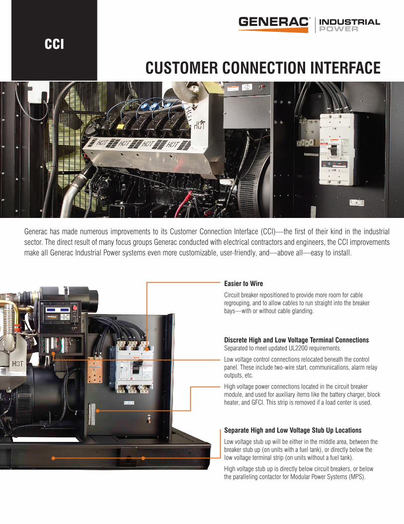
Easier to Wire
Circuit breaker repositioned to provide more room for cable regrouping, and to allow cables to run straight into the breaker bays—with or without cable glanding.
Discrete High and Low Voltage Terminal Connections Separated to meet updated UL2200 requirements.
Low voltage control connections relocated beneath the control panel. These include two-wire start, communications, alarm relay outputs, etc.
High voltage power connections located in the circuit breaker module, and used for auxiliary items like the battery charger, block heater, and GFCI. This strip is removed if a load center is used.
Separate High and Low Voltage Stub Up Locations
Low voltage stub up will be either in the middle area, between the breaker stub up (on units with a fuel tank), or directly below the low voltage terminal strip (on units without a fuel tank).
High voltage stub up is directly below circuit breakers, or below the paralleling contactor for Modular Power Systems (MPS).
gene rac .com
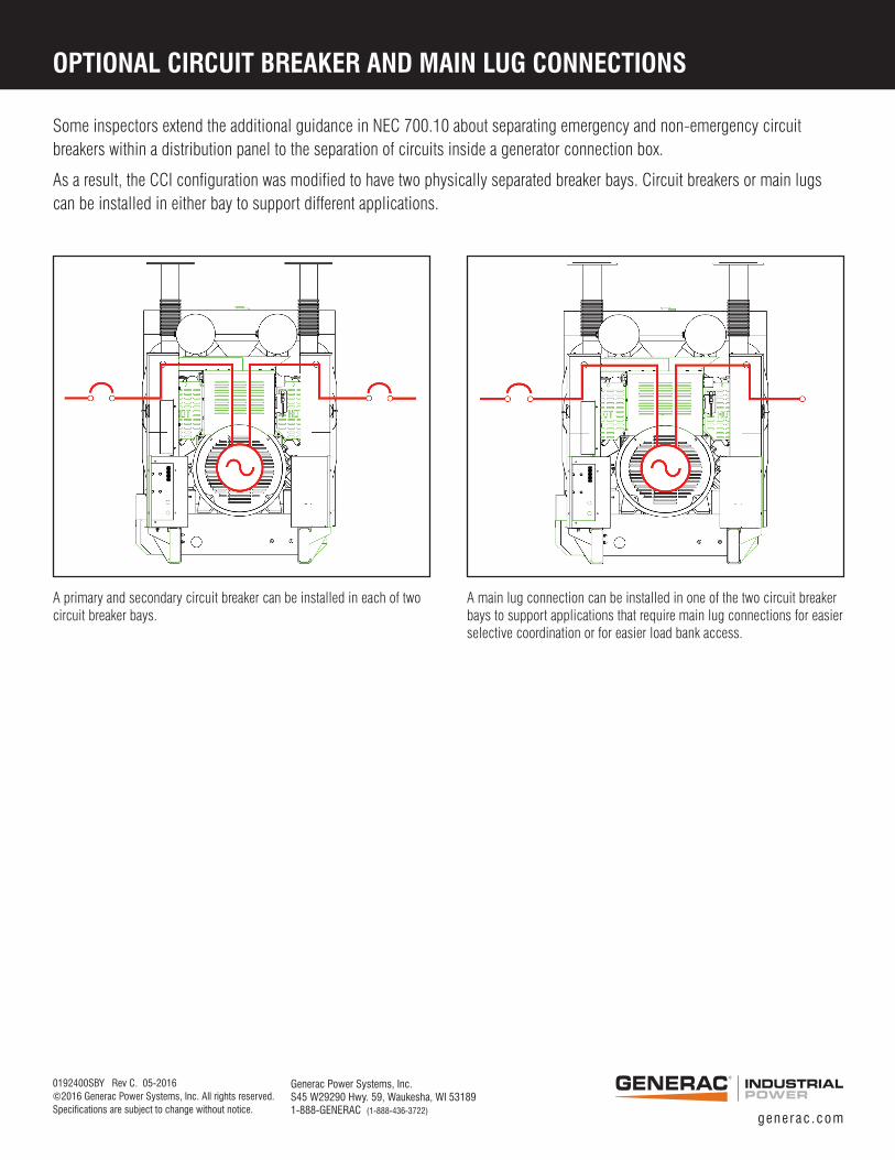
OPTIONAL CIRCUIT BREAKER AND MAIN LUG CONNECTIONS
Generac Power Systems, Inc.S45 W29290 Hwy. 59, Waukesha, WI 531891-888-GENERAC (1-888-436-3722)
0192400SBY Rev C. 05-2016 ©2016 Generac Power Systems, Inc. All rights reserved.Specifications are subject to change without notice.
A primary and secondary circuit breaker can be installed in each of two circuit breaker bays.
A main lug connection can be installed in one of the two circuit breaker bays to support applications that require main lug connections for easier selective coordination or for easier load bank access.
Some inspectors extend the additional guidance in NEC 700.10 about separating emergency and non-emergency circuit breakers within a distribution panel to the separation of circuits inside a generator connection box.
As a result, the CCI configuration was modified to have two physically separated breaker bays. Circuit breakers or main lugs can be installed in either bay to support different applications.