Embed Size (px)
Citation preview
FACILITY CONNECTION REQUIREMENTS
DOCUMENT
TECHNICAL REQUIREMENTS FOR
INTERCONNECTION TO THE NEBRASKA PUBLIC POWER DISTRICT
TRANSMISSION SYSTEM
Version 6.0 May 22, 2018
NPPD Operations System Planning & Transmission Business
Transmission Planning

Revision 5/22/18
Document Revision Dates Section Revision Date 1.0 Introduction 5/22/18 2.0 Purpose 5/22/18 3.0 General Interconnection Requirements 5/22/18 4.0 Reliability Requirements 5/22/18 4.1 Transmission Planning 5/22/18 4.2 Generation Facilities 5/22/18 4.3 Transmission Facilities 5/22/18 4.4 End-User Facilities 5/22/18 5.0 Technical Requirements 5/22/18 5.1 Power Quality 5/22/18 5.2 Engineering 2/23/10 5.3 Substations 3/1/10 5.4 Line Taps 5/22/18 5.5 System Protection 3/1/10 5.6 System Operations 5/22/18 5.7 System Control 5/22/18 5.8 Telecommunications 10/2/09 5.9 Metering 5/22/18 Attachment 1 : NPPD Generator Interconnection Data Request Form 10/2/09

Revision 5/22/18
Document Revision History Document Version Publish Date Version 1.0 December 2, 2000 Version 2.0 March 23, 2001 Version 2.1 June 27, 2001 Version 2.2 November 14, 2001 Version 3.0 January 14, 2005 Version 3.1 April 7, 2006 Version 3.2 August 9, 2007 Version 4.0 May 21, 2008 Version 4.1 August 17, 2009 Version 4.2 October 2, 2009 Version 4.3 March 1, 2010 Version 5.0 June 3, 2011 Version 5.1 June 15, 2012 Version 5.2 May 16, 2013 Version 6.0 May 22, 2018
Revision 5/22/18
Document Control List Department Contact, Title Transmission Planning Randy R. Lindstrom, Supervisor (Primary Contact) System Planning & Transmission Business Joel L. Dagerman, Manager Transmission System Control Center Ron O. Gunderson, Manager Engineering & Asset Management Jay R. Dring, Manager Delivery Art R. Wiese, Director Midwest Reliability Organization (Upon Request) Dan Schoenecker, VP Operations Southwest Power Pool (Upon Request) Lanny Nickell, VP Engineering
Revision 5/22/18
Table of Contents 1.0 INTRODUCTION............................................................................................................... 1
2.0 PURPOSE ........................................................................................................................... 2
3.0 GENERAL INTERCONNECTION REQUIREMENTS .................................................... 3
4.0 RELIABILITY REQUIREMENTS .................................................................................... 4
4.1 Transmission Planning ............................................................................................ 4
4.2 Generation Facilities ............................................................................................... 6
4.3 Transmission Facilities ......................................................................................... 10
4.4 End – User Facilities ............................................................................................. 11
5.0 TECHNICAL REQUIREMENTS .................................................................................... 12
5.1 Power Quality ....................................................................................................... 12
5.2 Engineering ........................................................................................................... 13
5.3 Substations ............................................................................................................ 14
5.4 Line Taps............................................................................................................... 14
5.5 System Protection ................................................................................................. 16
5.6 System Operations ................................................................................................ 17
5.7 System Control ...................................................................................................... 18
5.8 Telecommunications ............................................................................................. 19
5.9 Metering ................................................................................................................ 19
Attachment 1 : NPPD Generator Interconnection Data Request Form

1 Version 6.0
1.0 INTRODUCTION Nebraska Public Power District (NPPD) is a public corporation and political subdivision of the state of Nebraska. NPPD was formed in 1970 through the merger of Consumers Public Power District, Platte Valley Public Power and Irrigation District and the Nebraska Public Power System. The utility is governed by an 11-member Board of Directors, who is popularly elected from NPPD’s chartered territory. NPPD currently owns and operates transmission and subtransmission facilities encompassing nearly the entire state of Nebraska. NPPD’s chartered service territory includes all or parts of 86 of the 93 counties within the state. NPPD’s transmission network involves facilities energized at 115 kV or higher and operated as an interconnected electrical system. The NPPD transmission system is operated as a part of the Eastern Interconnected electrical network and is located on the western end of the Eastern Interconnection. The Eastern Interconnection spans a large portion of the Midwest and the entire eastern portions of the United States and is the largest interconnected grid in North America. NPPD is a member of the Midwest Reliability Organization (MRO) who is NPPD’s Regional Entity (RE). The MRO’s region is the central area of North America, including parts of both the United States and Canada. NPPD is a member of the Southwest Power Pool (SPP) Regional Transmission Organization (RTO). SPP is NPPD’s Planning Coordinator (PC) and Reliability Coordinator (RC). The SPP region includes the bulk electric grid and wholesale power market in the central United States. NPPD’s subtransmission facilities are operated at 34.5 kV – 69 kV and function as a radial power delivery system to provide for wholesale power deliveries to firm network service load customers. These customers are typically rural public power districts, municipal systems or large retail cities and towns.

2 Version 6.0
2.0 PURPOSE This document was developed to describe the general technical requirements for interconnection with the NPPD transmission system. This document provides an overview of the technical and reliability requirements to address interconnection requests. The interconnection requests include new facility additions and material modifications to existing facilities to accommodate generation, transmission, and end-user facilities which are being proposed for or planned to be connected to the NPPD transmission system. These requirements were established to promote safe operation, system integrity, reliability, and compliance with NERC Reliability Standards. These requirements are considered a minimum to be used as a guide toward processing of interconnection requests by NPPD. There may be additional requirements depending on the location and characteristics of the proposed interconnection facility and those requirements will be evaluated on a case by case basis.

3 Version 6.0
3.0 GENERAL INTERCONNECTION REQUIREMENTS All requests for interconnection to the NPPD transmission system must be consistent with NERC Reliability Standards, regional reliability requirements, and standard utility practices. A proposed interconnection must not degrade the reliability or operating flexibility of the existing transmission system. NPPD assumes responsibility to operate and maintain its interconnected facilities in accordance with NERC Reliability Standards and SPP requirements. System Impact Studies are required to evaluate the impact of the requested interconnection facility on the transmission system and to develop required facility plans to meet established reliability criteria. After acceptable completion of the System Impact Studies, a Facilities Study will be required to determine the detailed facility interconnection requirements. The Facilities Study will address direct assignment interconnection facilities, network upgrades, cost estimates, and construction scheduling estimates. All arrangements for system studies, engineering design, construction, ownership, operations, maintenance, replacement equipment, metering, facility controls, and telecommunications must be set forth in written contracts between NPPD and the requesting party. If additional equipment or replacement equipment is required to accommodate the facility interconnection, NPPD will retain equivalent transmission facility ownership, transmission capacity rights, and operational control as previously existed. The cost associated with equipment modifications is the responsibility of the requesting party. NPPD reserves the right to participate in the costs of proposed facility expansion plans that may be accommodated through mutually advantageous alternatives which provide substantial benefits to regional reliability or transmission transfer capability. The requesting party will generally be responsible for obtaining any necessary right-of-way or easements from landowners. All costs associated with environmental activities for the new facility will be the responsibility of the requesting party. Advance funds or deposits will be required by NPPD prior to any work being performed. A direct interconnection into NPPD’s transmission system does not guarantee transmission delivery capacity on the NPPD system or the SPP system. Transmission service requests must be made in accordance with SPP’s Open Access Transmission Tariff. The SPP Tariff and the requirements to become a transmission customer are posted on the Open Access Same-Time Information System (OASIS) and SPP’s website at www.spp.org.
4 Version 6.0
4.0 RELIABILITY REQUIREMENTS
4.1 Transmission Planning The Transmission Planning process is an important first step in the determination of interconnection feasibility. The transmission planning studies will identify impacts, deficiencies, operational issues, or interconnection facility concerns and evaluate potential solutions. For the purposes of this document, a new interconnection facility or a material modification to an existing facility shall be considered a proposed interconnection. A proposed interconnection must not degrade the reliability or operating flexibility of the existing power system. The proposed interconnection must comply with all NERC Reliability Standards. The proposed interconnection must also comply with all MRO and SPP requirements. The proposed interconnection must be reviewed and coordinated with all impacted transmission owners, affected systems, and approved by the SPP Planning Coordinator. NPPD will conduct or review System Impact Studies required to evaluate the system impact of a proposed interconnection on the reliability and capability of the transmission system. All costs to conduct or review System Impact Studies are the responsibility of the requesting party. The System Impact Studies will include, but are not limited to, powerflow, dynamic stability, and short circuit studies. Small Signal Stability Studies or Electro-Magnetic Transients Program (EMTP) studies may also be required, if deemed necessary. Evaluation of alternatives to the proposed interconnection, such as lower voltage construction, alternative interconnection points, reactive support facilities, or upgraded facilities, may be requested. Powerflow analysis will require 10-year load and resource growth projections and the planned facilities needed to satisfy all pre-existing long-term transmission service requirements. If the studies indicate that additions or upgrades to the existing transmission system are necessary, NPPD will conduct or review Facilities Studies, at the expense of the requesting entity, to determine the cost of additions or upgrades and the required timeframe for implementing system additions or upgrades. The transmission planning process for a proposed new interconnection facility or a material modification to existing facilities must also accommodate coordinated joint studies with other affected interconnected transmission system owners. Once a new or materially modified facility is considered feasible for interconnection, the requestor shall notify the Nebraska Subregional Planning Group (SPG) and/or the SPP Transmission Working Group (TWG). The Nebraska SPG and the SPP TWG provide an appropriate technical forum of regional transmission planners and transmission owners who can review proposed facility plans and readily identify concerns, issues, and impacts. The regional transmission owners and the requestors can work together to develop the most efficient transmission plan that will accommodate the proposed project and meet NERC Reliability Standards. Any transmission planning studies performed by either NPPD or others will need to be reviewed and coordinated with the appropriate impacted parties.

5 Version 6.0
The requestor shall provide the following detailed information for use in the transmission planning studies:
• Facility one-line diagram depicting detailed proposed interconnection points, voltage levels, equipment data, breaker / switch configurations and protective relay zones.
• Transformer impedance data, winding configurations, voltage levels, thermal ratings, and available tap ranges.
• Generator nameplate data and machine constants, generator voltage rating, step-up and auxiliary transformer data, impedance data and ratings.
• Generator rotor, governor, exciter, power system stabilizer and any other generator auxiliary data.
• Generator MW / MVAR levels, reactive capability curves, operational power factors and proposed load factors.
• Transmission line configuration, impedance and thermal ratings. Attachment 1 of this Facility Connection Requirements Document provides a detailed listing of all of the data requirements associated with a valid Generator Interconnection request. The requestor for a proposed facility shall specify the requested voltage level and MW / MVAR capacity and / or demand at the point of connection. For Generator Interconnection studies, the full nameplate capacity will be studied for injection at the requested location. All powerflow and stability studies will evaluate the impacts of the maximum capability of the requesting interconnection facility. Also the full approved capacity of other existing generators in the impacted region will be studied and maintained. Any special operational considerations or limitations associated with the interconnection facility shall be specified by the requestor. This information will be utilized to develop computer models of the requested facility for input into the transmission planning studies. Any specialized modeling development requirements are the responsibility of the requestor. The System Impact Study and Facilities Studies will typically be performed in multiple sequential stages. The System Impact Study will address a detailed powerflow analysis, dynamic stability analysis, short circuit analysis and any other required study work. The Facilities Study will detail the final interconnection facilities design, direct assignment facilities, costs and construction schedule estimates. The Facilities study will include a final Planning / Design study which will be formatted in accordance with NERC Reliability Standards and for submittal to SPP as the Planning Coordinator. Generator Interconnection requests directly to NPPD’s high voltage transmission system will need to follow SPP’s Generator Interconnection Procedures (GIP). The Interconnection Agreement for those requests will be under the SPP Generator Interconnection Agreement (GIA) process. The SPP GIP and GIA processes and standard interconnection agreement can be found at www.spp.org
6 Version 6.0
4.2 Generation Facilities When NPPD considers integrating a new generation facility interconnection into the NPPD transmission system, additional special studies may be required based on the requested location of the interconnection request. There are stability limitations in the western Nebraska area that will require significant transient stability analysis for any proposed generation additions which could affect the western Nebraska region. There are also other thermal or voltage constrained transmission interfaces that exist in Nebraska and are posted on the regional OASIS. Operational studies may also be required to evaluate impacts on present generation operations in the NPPD Settlement Area. All NPPD generation operates within the SPP Balancing Authority Area. All NPPD transmission facilities and load in the Eastern Interconnection is included within the metered boundaries of the SPP Balancing Authority Area. Any new generator interconnection or material modification to the NPPD transmission system will operate within the SPP Balancing Authority Area and abide by all requirements established by SPP. Operational issues on NPPD’s system, either during normal or emergency conditions, may affect SPP’s frequency control performance. Under certain conditions, the requesting generator interconnection may have to relinquish unit load and voltage control to NPPD’s Transmission System Control Center. The power factor for both the generating units and loads shall be measured at the interconnection point. Special region-specific operational studies will evaluate the transmission system and reliability considerations. Should replacement of existing equipment be required as a result of the interconnection, NPPD will retain equivalent ownership, transmission capacity, and operational control as previously existed. Automatic synchronization shall be supervised by a synchronizing check relay IEEE Device 25. This assures that no synchronous generator is connected to the power system out of synchronization. Generators must meet all applicable American National Standards Institute (ANSI) and IEEE standards. The prime mover and the generator should also be able to operate within the full range of voltage and frequency excursions that may exist on the NPPD system without damage to them. System voltage regulation is necessary for efficient and reliable electrical power delivery and for adequate service to loads. Voltage schedules establish hourly operating requirements and may be set for seasons, holidays, and days of the week or time of day. All interconnected generators are required to participate in voltage regulation by meeting voltage scheduling requirements. NPPD may require additional reactive capability or voltage regulations on some parts of its system to integrate the new generator interconnections. It is the generator owner’s responsibility to mitigate any unacceptable reactive or voltage regulation problems created due to the integration of the generator. If NPPD requires additional reactive or voltage regulation to solve other problems in an area, NPPD reserves the right to negotiate with the generator owner for any additional capability beyond the minimum requirements stated above. Synchronous generators are required to produce or absorb reactive power between .95 leading and .95 lagging power factors for steady state conditions to meet voltage schedules. Interconnected generators are also required to produce or absorb reactive power up to the thermal capability of the generator during transmission system disturbances. The voltage regulator must
7 Version 6.0
be capable of maintaining the voltage at the generator terminal bus without hunting and within 0.5 percent of any set-point. The operating range of the regulator shall be at least plus or minus 5 percent of the rated voltage of the generator. The excitation system of synchronous generators is required to be of a fast-response or High Initial Response type (the voltage response time is 0.5 seconds or less). A Power System Stabilizer (PSS) uses auxiliary stabilizing signals to control the excitation system to improve power system dynamic performance. A PSS is required with the excitation system for all interconnected synchronous generators 75 MVA and larger. However, it may be necessary to use a PSS on a smaller generator, depending on where the generator is interconnected to NPPD’s system and how this machine participates in critical damping modes within the region. A Small Signal Stability analysis may be required to determine the applicability of a PSS to any proposed interconnected synchronous generator. A speed governor system is required on all synchronous generators. The governor regulates the output of the generator as a function of the system frequency. That function (called the governor’s “droop” characteristic) must be coordinated with the governors of other generating units located within the NPPD control area to assure proper system response to frequency variations. The speed governor system shall have an adjustable droop characteristic setting typically set to 5 percent. NPPD’s system protection requirements are designed and intended to protect the NPPD transmission system. Additional protective relays will be required to protect a new interconnected generator. It is the generation owner’s responsibility to install the proper protective relaying needed to protect the generator equipment in coordination with NPPD system protection and applicable NERC / Regional standards. The owner of the generator is solely responsible for protecting interconnected equipment in such a manner that faults, imbalances, or other disturbances on the NPPD system are isolated by the owner’s protective equipment and do not cause damage to the interconnected generation facilities. For proposed wind or solar type generator interconnections, the new generating plant shall maintain a power factor within the range of 0.95 leading to 0.95 lagging, measured at the Point Of Interconnection as defined in the GIA. The power factor range standard can be met by using, for example, power electronics designed to supply this level of reactive capability (taking into account any limitations due to voltage level, real power output, etc.) or fixed and switched capacitors if agreed to by NPPD, or a combination of the two. The Interconnection Customer shall not disable power factor equipment while the wind or solar plant is in operation. Wind or solar plants shall also be able to provide sufficient dynamic voltage support in lieu of power system stabilizer and automatic voltage regulation at the generator Point Of Interconnection. The Generator Owner of the interconnected wind or solar plant shall provide, at a minimum, sufficient reactive power capability to deliver the generator plant output at unity power factor at the Point Of Interconnection. Power factor correction capacitors or other required reactive equipment must be installed either by the owner of the generation or by NPPD at the owner’s expense. Switched capacitor banks supplied by the generation owner shall be coordinated with NPPD voltage control requirements and switched at the request of NPPD. Dynamic reactive
8 Version 6.0
compensation through turbine based or substation based systems are also acceptable methods to provide voltage control at the point of interconnection. Dynamic reactive power compensation may also be required in addition to static power factor compensation at some locations. The System Impact Study will determine the reactive compensation required for the wind or solar generator interconnection. Wind generator interconnections are also required to meet the current technical standards for Low Voltage Ride Through capability and Power Factor Design Criteria (Reactive Power) as specified in FERC Order 661 and SPP Appendix G to the GIA. Power system disturbances initiated by faults and forced equipment outages expose connected generators to voltage and frequency oscillations. It is important that generators remain in service to help ensure that any dynamic or transient oscillations are stable and well damped. Therefore, each generator must be capable of continuous operation at 0.95 to 1.05 per unit voltage and 58.0 to 61.8 Hertz (per NERC PRC-024 frequency and voltage curves Attachments 1 & 2). For new inverter based generator interconnections, continuous operation does not include momentary cessation of real and reactive power injections during the disturbance event. Even larger voltage and frequency deviations may be experienced for short periods of time and interconnected generators must have capability for off-nominal operation. For new inverter based generator interconnections, the voltage protection functions in the inverters should be set based on physical equipment limitations to protect the inverter itself and not based solely on PRC-024 voltage ride through characteristic. Over/under voltage and over/under frequency relays are normally installed to protect the generators from extended off-nominal voltage / frequency operations. To ensure that the interconnected generators do not trip prematurely, the time delays for these relays must be coordinated with NPPD’s system protection schemes and current NERC requirements. A Remedial Action Scheme (RAS) automatically initiates one or more pre-planned corrective measures to restore acceptable power system performance following a disturbance. RAS application mitigates the impact of critical system disturbances and maintains system reliability. A typical disturbance, as considered in the planning and design of the electrical transmission system, is the sudden loss of one or more critical transmission lines or transformers. A widely applied corrective measure is to instantaneously reduce a sufficient amount of generation on the sending end of the lost transmission facility. This is known as generator “fast-valving” or “tripping”, and a participating generation facility may be disconnected from the transmission by the automatic RAS controller, in much the same way as by a transfer-trip scheme. A generation facility should therefore have full load-rejection capability as needed both for local line protection and RAS. NPPD has installed a RAS at Gerald Gentleman Station (GGS) to address system stability issues for Category P4 – P7 multiple contingency events and Extreme Events (NERC Standard TPL-001-4 Table 1). The status of critical lines and breakers, as well as fault occurrences, are continuously monitored. For combinations that would cause instability, a system of logic sends signals to trip GGS Unit #2. The GGS RAS initiation logic is dependent upon the “Eastflow” power transfer levels and prior outage conditions. “Eastflow” is defined by the total real powerflow on the following transmission lines: Gentleman – Sweetwater Circuit #1 345 kV

9 Version 6.0
Gentleman – Sweetwater Circuit #2 345 kV Gentleman – Red Willow 345 kV Gentleman – North Platte Circuit #1 230 kV Gentleman – North Platte Circuit #2 230 kV Gentleman – North Platte Circuit #3 230 kV Any new Generator Interconnection which impacts this western Nebraska stability limited region must be studied such that the existing approved firm capacity rights, as documented in NPPD’s FERC 715 filing, are preserved. The GGS Flowgate posting is considered a proxy flowgate posting for the GGS Stability Interface. Any new resources which impact this proxy flowgate must be studied through a detailed stability study process to determine the actual impacts on western Nebraska stability. The western Nebraska stability region has been studied in this incremental fashion since its inception and there are critical coordination requirements with the existing GGS RAS that must be adhered to. Failure to follow these procedures during new generator interconnection studies will result in an unreliable situation that could lead to instability, cascading, and loss of load to the entire western Nebraska area. These study procedures must be adhered to for any new generator interconnection study of this area in order to meet NERC Reliability Standards. Any proposed generation interconnection must not adversely affect the operation of the GGS RAS or degrade the reliability of the western Nebraska region. All dynamic stability analysis of the impacts of proposed generation interconnections affecting this region will be performed by or reviewed and approved by NPPD. Any required facility additions or modifications are the responsibility of the requesting party. The determination of the applicability of a RAS for a new interconnection facility must be consistent with the system performance requirements identified in NERC Standard TPL-001-4 - Transmission System Planning Performance Requirements Table 1 – Steady State & Stability Performance Planning Events.. In accordance with these standards, a new RAS is not applicable for mitigation of Category P0 – P3 Events. Depending on system design and expected system impacts, the planned removal from service of certain generators through the implementation of a RAS is a mitigation option for Category P4 – P7 and Extreme Events only. If NPPD requires RAS participation for a particular generation facility, the generator owner shall be responsible for all related costs. Generation integration may substantially increase fault current levels at nearby substations. Increased fault currents may exceed existing equipment ratings, interrupting ratings and/or through fault ratings. Any existing equipment replacement costs required due to fault currents associated with new generation is the responsibility of the requesting party. Modifications to the ground grids of existing substations may also be necessary to keep grid voltage rises within safe levels. The ground grid shall be designed to a minimum of ANSI/IEEE Standard 80-2000, IEEE Guide for Safety in AC Substation Grounding. Power system equipment is designed to withstand voltage stresses associated with expected operation. Interconnecting new generation resources can change equipment duty, and may require

10 Version 6.0
that equipment be replaced or switchgear, communications, shielding, grounding and/or surge protection added to restrict voltage stress to acceptable levels. System impact and/or Facilities studies will need to include the evaluation of the impact of the interconnected generator on equipment insulation coordination. Surge protection requirements will be in accordance with ANSI C37.90.1 – 1989-1994. NPPD will review breaker duty and surge protection to identify any additions required to maintain an acceptable level of NPPD system availability, reliability, equipment insulation margins and safety. All generation equipment ratings shall be submitted to NPPD and to the regional RTO and RE in accordance with their data submittal requirements. Attachment 1 (NPPD Generator Interconnection Data Request Form) provides a detailed listing of all of the data requirements associated with a Generator interconnection request.
4.3 Transmission Facilities Any proposed transmission facility interconnecting into NPPD’s high voltage transmission system shall be coordinated and reviewed through the Transmission Planning process described in Section 4.1. The transmission facility addition shall maintain or improve the level of system reliability which existed prior to the interconnection. Power flows as a result of the transmission interconnection shall not overload or adversely affect the NPPD Transmission System or the SPP Regional Transmission system. Voltage levels shall be coordinated with NPPD’s existing transmission system and substation operational voltage levels. Currently, NPPD’s existing transmission system voltage levels are 345 kV, 230 kV, 161 kV and 115 kV. The transmission line / substation design and construction shall be in accordance with NPPD’s transmission line / substation design and construction standards. A transmission system switching study may be required to evaluate transient overvoltages caused by switching operations involving the proposed new transmission line. This study will be required for proposed 345 kV transmission facilities to address insulation coordination requirements due to potential switching surges. Also, proposed lower voltage transmission lines which are electrically close to existing 345 kV facilities may require a switching surge study in order to determine the Basic Insulation Level (BIL) requirements and / or switching voltage surge protection requirements for the proposed new facilities. The requestor is responsible for all Nebraska State required approvals, environmental requirements, protection coordination, interconnection metering, maintenance and control coordination. The thermal ratings for the proposed transmission facilities shall also be provided to NPPD and subsequently submitted to SPP. The thermal ratings shall be coordinated with industry standards and NPPD’s thermal rating assumptions contained in NPPD’s Facility Ratings Methodology document.

11 Version 6.0
4.4 End – User Facilities Typical end-user facilities considered for interconnection would encompass load (dynamic and static), reactive devices (capacitors and reactors), or Battery Energy Storage Systems. The impacts on the transmission system must be studied to address any special operational limitations or facility requirements. All end-use load connected directly to the NPPD system are to maintain a power factor between 0.95 lag and 0.95 lead as measured at the point where the load interconnects with NPPD-owned facilities. If this power factor requirement is not met, NPPD may install power factor correction equipment at the load owner’s expense. NPPD maintains transmission voltages at levels required for the reliable delivery of electricity. Regulation to keep voltage variations within limits acceptable to end-use customers is typically provided at the distribution system level. Voltage regulation at transmission voltage levels is different from distribution voltage levels. NPPD maintains transmission voltage levels between 0.95 – 1.05 Per Unit during normal conditions and between 0.90 – 1.10 Per Unit during emergency conditions. Load owners are strongly urged to install their own voltage regulation equipment and coordinate any voltage set points or time delays with the normal transmission voltage bandwidths. All end-user facilities connected to the NPPD system must meet the power quality standards set forth in Technical Requirements for Power Quality (Section 5.1). The requestor is responsible for any mitigation efforts necessary to meet those standards. NPPD’s system protection requirements are designed and intended to protect the NPPD system. Additional protective relays are required to protect an interconnected end-user facility. It is the requestor’s responsibility to install the proper protective relaying needed to protect the end-user facilities. NPPD does not assume responsibility for protection of the interconnected end-user facilities. The requestor is solely responsible for protecting interconnected equipment so that faults, imbalances or other disturbances on the NPPD system do not cause damage to the end-user facilities. To meet the reliability requirements of NERC, MRO and SPP, under frequency and/or under voltage load shedding schemes may be required. Any load or reactive device connected to the NPPD system will be expected to participate in under frequency or under voltage load shedding if NPPD determines such action is necessary to maintain system reliability. If NPPD requires load-shedding participation for a particular end-user facility, the requestor shall be responsible for all related costs.

12 Version 6.0
5.0 TECHNICAL REQUIREMENTS
5.1 Power Quality Unbalanced phase voltages and currents can affect protective relay coordination and cause high neutral currents and thermal overloading of transformers. To protect NPPD and customer equipment, the interconnected facility contribution at the point of interconnection shall not cause a voltage unbalance (Phase to Phase) greater than 2 %, or a current unbalance greater than 5 %. Algorithms that use only the r.m.s. values to calculate unbalance, fail to take into account the contributions of angular displacement to unbalance and cause unpredictable results when harmonic voltages are present. The negative sequence and zero sequence unbalance provide more precise and more directly useful values and should be measured with equipment conforming to IEC 61000-4-30, Class A instrumentation, and IEC 61000-4-15 Any switching operation or energization of the Customer’s facilities will not cause a voltage change (delta V) of greater than 3 % at the point of interconnection with NPPD. Application examples are; energizing the step-up transformer or any fixed shunt switching operation. The measurement will be in accordance with IEC 61000-4-30 and based on a ½ cycle average, from the preceding waveform of each phase of voltage As evidence of a Customer’s ability to consistently meet the 3% or less voltage change requirement, NPPD recommends the performance and documentation of not less than four consecutive successful switching operations or energizations as a sufficient test. A single successful switching operation or energization is not deemed to be an adequate test of a Customer’s ability to consistently meet the requirement. Harmonics can cause telecommunication interference, thermal heating in transformers, disruptions to solid state equipment and resonant over voltages. To protect equipment from damage, harmonics must be managed and mitigated. The interconnected generator/load shall not cause voltage and current harmonics on the NPPD system that exceed the limits specified in Institute of Electrical and Electronics Engineers (IEEE) Standard 519-2014. Harmonic distortion is defined as the ratio of the root mean square (rms) value of the harmonic to the rms value of the fundamental voltage or current. Single frequency and total harmonic distortion measurements may be conducted at the point of interconnection, generation/load site or other locations on NPPD’s system to determine whether the project is the source of excessive harmonics. Many methods may be used to restrict harmonics. The preferred method is to install a transformer with at least one delta connection between the generator/load and the NPPD system. This method significantly limits the amount of voltage and current harmonics entering the NPPD system. Voltage fluctuations may be noticeable as visual lighting variations (flicker) and can damage or disrupt the operation of electronic equipment. IEEE Standard 519-2014, IEEE Standard 1453-2015 and IEC 61000-4-15 provide definitions and limits on acceptable levels of voltage

13 Version 6.0
fluctuation. The system shall be designed such that the maximum voltage fluctuation for starting motors, switching transformers, and switching reactive devices will be 3 % or less. All generators/loads connecting to the NPPD system shall comply with the limits set by this Standard. Special studies, such as Electro-Magnetic Transients Program (EMTP) may be required to analyze the power quality impacts of a proposed facility. The customer will be responsible for the costs of any required special studies.
5.2 Engineering NPPD will provide for engineering design and specifications of the proposed interconnection for NPPD owned facilities. All engineering costs and engineering review costs for NPPD owned facilities are the responsibility of the requesting party. For facilities owned by others, prints of applicable drawings will be furnished to NPPD upon request. If the interconnected facilities are to be owned by NPPD, then any new land rights necessary for the interconnection may be acquired by NPPD from the affected landowners, at the expense of the requesting entity. In certain circumstances, the requesting entity may acquire these additional land rights, provided they coordinate with NPPD as to what rights are necessary. Modifications to NPPD’s transmission system to accommodate the proposed interconnection shall adhere to NPPD’s Standards. Any variation from the NPPD Standards may be considered on a case-by-case basis. NPPD’s Standards will be furnished after the initial Letter of Agreement is signed. The requesting entity will supply drawings via an electronic file or other common storage device, compatible with NPPD’s computer-aided design system, AutoCAD. If NPPD will operate and maintain the facilities, the Drawings for facility additions must conform to NPPD’s Drafting Standards and be approved by NPPD. The requesting entity will reimburse NPPD for drawing costs. Copies of NPPD’s Drafting Standards will be furnished to the entity requesting the interconnection if the design is not produced by NPPD. “As-built” drawings must be provided prior to final approval by NPPD. Three complete sets of accurate substation drawings shall be provided to NPPD for non-NPPD-owned substations. These drawings shall include, but not be limited to, station plot plans, equipment layouts, single-line diagrams, control circuit schematics and wiring diagrams. Updated copies of these drawings shall be furnished to NPPD within 60 days of any modification to non-NPPD owned equipment or substations on NPPD’s system. Breakers and switches installed in NPPD substations shall adhere to NPPD numbering schemes. Breaker and switch operation numbers will be assigned by NPPD. All switches to be operated by NPPD will be locked with locks furnished by NPPD. All switches to be operated by NPPD shall be designed in accordance with NPPD’s Standards.
14 Version 6.0
5.3 Substations Generally, power circuit breakers must be installed at all interconnections with NPPD’s system. Typical specifications covering circuit breaker requirements are available from NPPD upon request. A review of the surrounding area power system characteristics, including system stability studies, will be made for a final determination when the need for out-of-step switching capability is questionable. Installation of equipment in substations must conform to NPPD’s requirements and must be approved by NPPD. All Oil-filled equipment, including bushings, shall not contain polychlorinated biphenyls (PCB’s). In addition, oil-filled equipment shall be permanently labeled by the manufacturer as non-PCB (less than 2 parts/million). Certification shall be provided to NPPD at or before the time of installation. Oil-filled equipment may require an oil spill containment system to comply with U.S. Environmental Protection Agency or state regulations. Any increased equipment costs due to these requirements will be borne by the requesting entity. The owner of installed equipment will be responsible for its proper operation and maintenance. Equipment must be operated and maintained in accordance with manufacturer’s recommendations, prudent utility practices, applicable NERC / Regional standards, and applicable environmental and safety standards. NPPD may require additional equipment to assure a reliable interconnection and to safeguard the proper operating conditions of its power system. NPPD prefers, in many cases, to provide required O&M services provided funds have been advanced to cover these costs. Costs may include training on maintenance procedures for unfamiliar equipment. The interconnection substation must have a ground grid that solidly grounds all metallic structures and other non-energized metallic equipment. This ground grid shall limit the ground potential gradients to such voltage and current levels that will not endanger the safety of people or damage equipment located in, or immediately adjacent to, the substation under normal and fault conditions. The ground grid shall be designed to ANSI/IEEE Standard 80-2000, IEEE Guide for Safety in AC Substation Grounding. NPPD personnel will conduct an inspection of the new substation interconnection facilities prior to the energization of these facilities. The inspection requirements will be consistent with the inspection requirements of existing substation facilities. Only after a satisfactory inspection is completed will the new substation interconnection facilities be authorized for energization and synchronization.
5.4 Line Taps Proposed taps to NPPD’s Sub-transmission system (69 kV and 34.5 kV) are subject to approval by NPPD on a case-by-case basis. Additional taps can be placed on existing sub-transmission lines as long as thermal and voltage criteria are maintained and all loads can be fed radially from the normal transmission delivery point.

15 Version 6.0
Taps to sub-transmission lines of 69 kV and 34.5 kV must meet the following minimum criteria:
1.) A line section protected by a circuit breaker may have a mileage maximum for tap lines that are not protected by circuit breakers, determined on a case-by-case basis.
2.) A proposed interconnection to an existing radial sub-transmission line, whenever possible, will be connected to the line at an existing tap.
3.) New lines of 34.5 kV and above will have overhead ground wire shielding over the entire length of the tap-line. A breaker may be required for the tap line due to relaying or specific reliability criteria.
4.) SCADA-controlled interrupter switches (or equivalent) capable of interrupting load and charging current shall be installed in the line sectionalizing positions for all tap
substations. These interrupters will be used to de-energize line sections without interruption of the tapped loads, if necessary. Line sectionalizing switches installed in sub-transmission lines shall be furnished with grounding blades, and must have a visible air gap. Normally, NPPD assumes ownership of the sectionalizing switches. If NPPD does not assume ownership, however, NPPD will still maintain operational control.
5.) An ungrounded high voltage winding is the preferred transformer connection on the tapped 69 kV or 34.5 kV line.
The tap should not adversely affect the protection scheme or outage frequency on the present tap(s). Additional taps can be placed on existing lines where delta-wye transformers are used. Auto-transformers or three-winding transformers present sources of zero sequence current and can make both directional ground over current and ground distance relaying complicated. Taps to transmission lines of 115 kV, 161 kV, 230 kV and 345 kV system voltages will not be allowed since lines at these voltage levels make up the Bulk Electric System and require the highest level of reliability. If a sufficient MW level of a proposed interconnection facility requires interconnection at the 115 kV, 161 kV, 230 kV or 345 kV level, then this will require fully breakered interconnection facilities and this interconnection and final facility plan is subject to approval by NPPD. Any new proposed interconnection to NPPD’s 230 kV and 345 kV bulk network will be required to provide the identical level of reliability that existed prior to the new interconnection. In general, this equates to sufficient redundancy in the new substation interconnection such that there are no new stuck breaker contingency events which will result the loss of the previous bulk line configuration. Any new requested interconnection point on the 230 kV or 345 kV network must be planned to maximize the future transmission development opportunities and to minimize adverse impacts to the reliability of the system. Any new requested interconnection point that is within 25 Miles of an existing high voltage (230 kV or 345 kV) substation, will be directed to interconnect to the

16 Version 6.0
existing substation. Once a new interconnection point is approved by NPPD and established on the bulk transmission system, that point will become a designated hub for future generator interconnection requests that are within a 50 Mile radius. Entities requesting non-NPPD designed sub-transmission line taps shall submit designs, calculations and drawings demonstrating that the structures and foundations have been designed in accordance with NPPD’s Standards.
5.5 System Protection Protective relaying requirements for each interconnection and relay scheme coordination will be determined by NPPD after review of the proposed interconnection and short circuit study work. NPPD requires receipt of a preliminary functional single-line drawing including relaying, current/potential transformer and basic control/tripping connections for the proposed interconnection and a single-line drawing and maps of the requesting entity’s system in the area. Any proposed pilot protection scheme (POTT, DCUB, DTT, etc…) including proposed communications channel and relay connections should be provided. The requestor will be required to provide all equipment ratings and positive, negative and zero sequence impedance data necessary to adequately model the proposed interconnection facility in a short circuit analysis. See requirements in attachment 1. The requestor should also provide re-closer and fuse ratings, and relaying data necessary to address protective relaying coordination in accordance with NERC / Regional standards and requirements. High-speed piloted or communication assisted primary relaying, secondary relaying, breaker failure, and out-of-step relaying are normal NPPD requirements for 115 kV and higher voltage interconnections. NPPD will determine if the primary relaying scheme needs to be piloted, both the primary and secondary schemes needs to be piloted or if no piloted schemes are necessary for system stability. All short lines will have dedicated fiber for line differential relays for protection as determined by NPPD. Specialized relaying may be required to provide automatic load, generation shedding or interconnected system separation. The NERC technical paper for Protection System Reliability will be applied on all BES equipment. The protection system will comply with all applicable NERC PRC standards. The Protection system involves the protective relays, voltage and current sensing devices, associated communication equipment, DC circuitry and Batteries as defined by the NERC PRC standards. Protective relays and control systems must be inspected and tested by functional trip checking prior to putting any interconnected facility in service. The future maintenance and testing shall be in accordance with NPPD’s Protective Relaying & Maintenance Procedures. NPPD personnel will need to be notified with procedures prior to and during any future maintenance and testing of protective relaying devices. The requesting entity is responsible for the costs associated with the ongoing testing and maintenance of the protective relaying and control equipment.

17 Version 6.0
5.6 System Operations Following the execution of an Interconnection and Operating agreement and the successful completion of all construction, inspection and facility checkout procedures, the interconnected facility will be released for energization. The initial synchronization will be supervised and coordinated with NPPD personnel. Future synchronization will be controlled by NPPD Transmission System Control (TSC) personnel and will either be automatic or manual per the direction of NPPD TSC. All communications and operating procedures during normal and emergency operating conditions will be initiated and controlled by NPPD TSC personnel. Any requests from the interconnected facility for any special operating considerations will be submitted to NPPD TSC for review and approval prior to execution. Emergency operating conditions will be handled in accordance with NERC Standards and good utility practice. The interconnection facility must recognize the dynamic nature of an interconnected transmission system and the reliability and safety priorities of the NPPD TSC. NPPD TSC personnel may not be available immediately during all emergency conditions and the NPPD TSC will communicate the system status and any special operating restrictions to the interconnected facility as soon as feasible. Circuit breakers, disconnects, interrupters and motor-operated disconnect switches that are an integral part of NPPD’s transmission system shall be operated and dispatched by NPPD TSC personnel located at the NPPD Doniphan Control Center. The NPPD Doniphan Control Center will direct switching and issue all clearances, hot-line orders and general switching on the transmission portion of the interconnection or substation. This will involve use of approved NPPD switching and clearance procedures, including use of NPPD locks and tags. The requesting entity making the interconnection will write Standard Operating Procedures in coordination with NPPD for the interconnected facility. Three sets of instructions and manufacturer’s drawings shall be furnished to NPPD for each piece of equipment that NPPD operates. If construction activities are performed by other entities, NPPD may require at least one NPPD representative be present to coordinate and provide for switching, clearances, special work permits and inspections during construction work on NPPD’s right-of-way. The NPPD representative will also conduct or observe the operability checkout on equipment, including metering, relay settings and tests and protective device operation (circuit breakers, motor-operated disconnects, etc.). Final electrical connections to NPPD’s system will be made by NPPD or under NPPD’s supervision. Maintenance will normally be performed by and at the expense of the entity that owns the equipment or facility when the proposed interconnection involves a tap or substation sectionalizing one of NPPD’s transmission lines. NPPD shall be notified and have the right to witness settings and testing of relays, meters and controls that could affect the integrity and security of NPPD’s transmission system. NPPD shall also have the right to enter interconnected

18 Version 6.0
facilities for emergency operation and maintenance of equipment or structures NPPD deem necessary to maintain a reliable power system.
5.7 System Control Supervisory control by NPPD of circuit breakers, interrupters or motor-operated disconnects will be required on all interconnections that directly affect the security of NPPD’s transmission system. The Remote Terminal Units (RTU’s) for supervisory control shall be compatible with the Energy Management System (EMS) / SCADA system used within the NPPD system. The cost of providing and installing the RTU at a new location or proportionate cost of modifying an RTU at an existing facility will be at the expense of the requesting entity. NPPD will perform the necessary expansion, including hardware and software changes, to the EMS / SCADA master station equipment at the requesting entity’s expense for that portion attributed to the new interconnection. Transducers, interface hardware and appropriate communication channels compatible with existing EMS / SCADA system requirements shall be furnished by the requesting entity. Specifications for such equipment will be provided upon request. The requesting entity shall provide necessary auxiliary and control relays, hot-line indication, supervisory local / remote switches, and all other equipment necessary to interface with NPPD’s supervisory control equipment. Any new wind power generation interconnection facility will be required to provide a SCADA system with the ability to interface in real time with the NPPD Doniphan Control Center (Reference Appendix G of FERC Order 661A). Interconnections that establish additional or new balancing area boundaries require the requesting entity to furnish all necessary balancing area metering equipment. These requirements may include, but are not limited to:
(1) Analog and/or digital telemetering at the point of interconnection.
(2) Analog to digital conversion equipment and tone gear, as required, at both the point of interconnection and NPPD’s Doniphan Control Center.
(3) Totalizing equipment at the point of interconnection or some intermediate point on
the communications link. A multiport RTU may be substituted in some cases. If a multiport RTU is used, a points list identifying alarms, events and telemetered quantities will be jointly developed between the requesting entity and NPPD. The service agreement implementing the multiport RTU will include operating/dispatch jurisdiction, primary and backup service control protocol, SCADA tagging and control design, switching procedures and definitions of terms used by the system operators.
(4) Automatic Generation Control (AGC) hardware and software modifications to
NPPD’s Doniphan Control Center and SPP’s Control Center.

19 Version 6.0
NPPD’s telemetering, scheduling and interconnection metering are performed on a megawatt or whole megawatt hour basis, therefore, interconnection metering and totalizing equipment shall meet this criterion. NPPD reserves the right to maintain backup control on all facilities that interconnect with NPPD’s transmission system and that may be vital to system stability and telemetry values.
5.8 Telecommunications The requesting entity shall provide telecommunications facilities sufficient to meet NPPD’s telephone, radio, system protection, remote meter reading and EMS / SCADA requirements. The communication channel and channel hardware will be provided by the requesting entity. NPPD will specify the type, speed and characteristics of the communication channel equipment so that compatibility with existing communications, supervisory control, relaying and telemetering equipment is maintained. The specific type of communication equipment to be furnished by the requesting entity will be reviewed and approved by NPPD. The requesting entity will reimburse NPPD for the costs of any additional facilities provided by NPPD. Fiber optic additions to new or existing NPPD transmission lines will be considered on a case-by-case basis. Technical analysis of clearances, structural loads, and electrical field effects may limit applications. Outage restrictions and maintenance responsibilities may also impact potential paths. NPPD reserves the right to charge a fee for ROW, pole attachments and/or acquire individual optical fibers on the circuit, per agreement between the interconnecting entity and NPPD.
5.9 Metering NPPD will procure, supply and maintain all required metering equipment at the requestor’s expense. Current transformers used for revenue metering circuits must meet the accuracy standards, as specified under ANSI C57.13-2016, for an accuracy class of 0.15S, as indicated by ANSI C57.13-2016 Table 8,at all burdens. The thermal current rating of current transformers shall exceed the maximum current capacity of the circuit involved by a factor of 1.5 to 2.0. Coupling capacitor voltage transformers (CCVTs) will not be used for metering. Voltage transformers used for revenue metering circuits must meet the accuracy standards, as specified under ANSI C57.13-2016, of 0.15 accuracy with the following burdens as indicated by ANSI C57.13-2016 Table 19:
(1) “W” through “Y” burden for systems 25-kV and below
(2) “W” through “Z” burden for systems above 25-kV.

20 Version 6.0
Revenue metering with mass memory storage shall be used if the estimated maximum demand is 500 KVA or greater, or if maximum simultaneous demand billing is contractually required. Revenue metering for systems 1MW or greater shall have remote communications capability compatible with NPPD billing and SCADA systems. Such revenue metering shall be compatible with the metering policy established by NPPD.

21 Version 6.0
Attachment 1
NPPD Generator Interconnection Data Request Form
Requestor: Organization: _________________________ Contact: _________________________ Address: _________________________ _________________________ Phone: _________________________ E-Mail: _________________________ Interconnection Site Information: ______ Proposed New Generation Facility ______ Increased Capacity At An Existing Generation Site Physical Location Site Description (County, City, Address, etc.): _____________________________________________________ _____________________________________________________ _____________________________________________________ Electrical Location Site Description (Point of Interconnection): _____________________________________________________ _____________________________________________________ Attached One-Line Diagram ? (Y/N) _____ Generator General Information: Fuel Type (Coal, Diesel, Wind, etc.): _________________ Maximum Total Generation Capacity (MW): _________________ Number of Generating Units: _________________ Generator Type (Synchronous / Induction): _________________ Expected Commercial In-Service Date: _________________ Expected Initial Synchronization Date: _________________ Generator Nameplate Ratings: Machine MVA: _______ Power Factor: _______ Terminal Voltage (kV): _______ Machine Speed (RPM): _______ Frequency (Hz): _______ Short Circuit Ratio: _______
22 Version 6.0
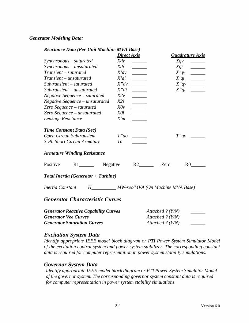
Generator Modeling Data: Reactance Data (Per-Unit Machine MVA Base) Direct Axis Quadrature Axis Synchronous – saturated Xdv ______ Xqv ______ Synchronous – unsaturated Xdi ______ Xqi ______ Transient – saturated X’dv ______ X’qv ______ Transient – unsaturated X’di ______ X’qi ______ Subtransient – saturated X”dv ______ X”qv ______ Subtransient – unsaturated X”di ______ X”qi ______ Negative Sequence – saturated X2v ______ Negative Sequence – unsaturated X2i ______ Zero Sequence – saturated X0v ______ Zero Sequence – unsaturated X0i ______ Leakage Reactance Xlm ______ Time Constant Data (Sec) Open Circuit Subtransient T”do ______ T”qo ______ 3-Ph Short Circuit Armature Ta ______ Armature Winding Resistance Positive R1______ Negative R2______ Zero R0______ Total Inertia (Generator + Turbine) Inertia Constant H__________ MW-sec/MVA (On Machine MVA Base)
Generator Characteristic Curves Generator Reactive Capability Curves Attached ? (Y/N) ______ Generator Vee Curves Attached ? (Y/N) ______ Generator Saturation Curves Attached ? (Y/N) ______
Excitation System Data Identify appropriate IEEE model block diagram or PTI Power System Simulator Model of the excitation control system and power system stabilizer. The corresponding constant data is required for computer representation in power system stability simulations.
Governor System Data Identify appropriate IEEE model block diagram or PTI Power System Simulator Model of the governor system. The corresponding governor system constant data is required for computer representation in power system stability simulations.

23 Version 6.0
• Note: If actual generator data is not available, NPPD will work with the customer to develop representative modeling data for use in the System Impact Study. Once the facility is constructed and tested, the models must be updated with actual data and the complete data and test results must be provided to NPPD.
Wind Generator Data
Number of Wind Turbines to be connected at the Point of Interconnection ______ Type of Induction Generating Unit _________________________ Manufacturer _____________________ Nameplate Rated MVA ________ Unit Maximum Output (MW) ________ Power Factor Control Characteristics ___________________________________ Voltage Control Characteristics ________________________________________
• Note: Detailed dynamic modeling data for the specified wind turbines is required for
computer representation in power system stability simulations. This includes data required to develop a detailed generator/converter model, electrical control model, turbine, and turbine control model. The data is required in compatible IEEE or PTI PSS/E format.
Generator Step-up (GSU) Transformer Data
Generator Step-up Transformer MVA Base ________ Generator Step-up Transformer Rating(s)(MVA) ________ GSU Transformer Voltage Ratings H________ L________ T________ GSU Winding Connection (Wye/Delta) H________ L________ T________ Available Fixed Taps __________________________________________ Present Fixed Tap Setting __________
Generator Step-up Transformer Impedance (R+jX or % R & % X on transformer MVA Base)
Positive Sequence R X MVA Base
H-L ________ ________ ________ H-T ________ ________ ________ L-T ________ ________ ________ Zero Sequence T-Model
• Note: Following construction and testing, transformer test reports must be provided to NPPD.