Embed Size (px)
Citation preview
1. Roport No. 2. Go•orn"'•"'' Ace•••••" No.
FHWA/TX-88+481-1
.C. T itlo e"cl Sublitlo
EFFECT OF FLY ASH ON THE SULFATE RESISTANCE OF CONCRETE CONTAINING FLY ASH
7. Author/ a)
P. J. Tikalsky and R. L. Carrasquillo
9. Porlorming Organi aolion Name and Aclclrou
Center for Transportation Research The University of Texas at Austin Austin, Texas 78712-1075
TECHNICAL REPORT STANDARD TITLE PAGE
5. Report Dot•
February 1988 6. Porlormil\g Orgontaotton Cod•
8. Porlorllling Organi a ali on Roport No.
Research Report 481-1
10. Work Unit No.
11. Contract or Gront No.
Research Study 3-5/9-87-481 !
1-:-;:--:---:----:---:-:---:-:--:-:-----------------..j 13. Type of Roporl and Period Cove rod t:l. Sponaoring Agency Name and Addrua
Texas State Department of Highways and Public Transportation; Transportation Planning Division
P. 0. Box 5051
Interim
l.C. Sponao'""" Agoncy Cocio
Austin, Texas 78763-5051 lS. SupplerftOntory Natu
Study conducted in cooperation with the U. S. Department of Transportation, Federal Highway Administration
Research Study Title: "Durability and Performance of Concrete Containing Fly Ash" 16. Abatroct
The durability of concrete is determined by its ability to endure the physical and environmental surroundings without losing the functional properties and structural integrity of the original design. Concrete containing fly ash can be proportioned to meet the durability requirements of a wide range of applications, such as concrete for mass structure, pavements, structural members, and high strength applications. One area where the long term performance of concrete containing high calcium fly ash has been suspect is in sulfate environments. The sulfate attack mechanism in concrete containing fly ash has been related in recent years to the mineralogical and chemical characteristics of portland cement and fly ash and their proportions, and the sulfate resistance of concrete containing fly ash. This report summarizes the results of the first year of the study. Fourteen fly ashes and four portland cements have been studied at four cement replacement levels and two different workability levels. A wet chemis::ry analysis was performed to determine the bulk chemical properties of both the fly ashes and the portland cements. The mineralogy of the fly ash was determined by XRD analysis. Over 500 concrete specimens have been exposure tested in a 10 percent sodium sulfate solution and monitored for mass change and linear expansion. The study has revealed a possible correlation between the tricalcium aluminate content of the high calcium fly ash and sulfate deterioration. In addition, the results to date indicate that lignitic fly ashes result in sulfate resistant concrete. This is an interim report of an ongoing investigation to the problem of sulfate attack of concrete containing fly ash. 17. Koy Warda
fly ash, portland cement, sulfate attack, mineralogy, expansion, durability, hydration
11. Oiatrll>\ltillft $tet-ent
No restrictions. This document is available to the public through the National Technical Information Service, Springfield, Virginia 22161.
19. Socurity Clouif. lof thia roport) 20, Security Cloulf. (of thi a page) 21. No, of P ogol 22. P rico
Unclassified Unclassified 110
Form DOT F 1700.7 Ct•6tJ

EFFECfOFFLY ASHONTHE SULFATE RESISTANCE OF CONCRETE
CONTAINING FLY ASH
by P. J. Tikalsky
and R. L. Carrasquillo
Research Report Number 481-1 Durability and Performance of Concrete Containing Fly Ash
Research Project 3-5/9-87-481
Conducted for Texas
State Department of Highways and Public Transportation in cooperation with the
U. S. Department of Transportation Federal Highway Administration
by
Center for Transportation Research Bureau of Engineering Research
The University of Texas at Austin
February 1988
The contents of this report reflect the views of the authors who are responsible for the facts and accuracy of the data presented herein. The contents do not necessarily reflect the views or policies of the Federal Highway Administration. This report does not constitute a standard, specification or regulation.
ii
PREFACE
This is the first in a series of reports summanzmg the durability and performance of concrete containing fly ash. This report is a interim report on the sulfate resistance of concrete containing fly ash. Other reports will address the topics of scaling resistance, abrasion resistance, freeze-thaw durability, creep and shrinkage at early ages, and fly ash characterization.
This work is part of Research Project 3-5/9-87-481, entitled "Durability and Performance of Concrete Containing Fly Ash." The study described in this report was jointly conducted by the Center for Transportation Research, Bureau of Engineering Research, the Phil M. Ferguson Structural Engineering Laboratory at the University of Texas at Austin and private industry. The work was co-sponsored by the Texas State Department of Highways and Public Transportation and The Federal Highway Administration.
The overall study was directed and supervised by Dr. Ramon L. Carrasquillo.
iii

ABSTRACI'
The durability of concrete is determined by its ability to endure the physical and environmental surroundings without losing the functional properties and structural integrity of the original design. Concrete containing fly ash can be proportioned to meet the durability requirements of a wide range of applications. such as concrete for mass structure, pavements, structural members, and high strength applications. One area where the long term performance of concrete containing high calcium fly ash has been suspect is in sulfate environments. The sulfate attack mechanism in concrete containing fly ash has been related in recent years to the mineralogical and chemical composition of the cementitious and pozzolanic material. This study is being conducted to investigate the interrelationship between the physical, mineralogical and chemical characteristics of portland cement and fly ash and their proportions, and the sulfate resistance of concrete containing fly ash. This report summarizes the results of the first year of the study. Fourteen fly ashes and four portland cements have been studied at four cement replacement levels and two different workability levels. A wet chemistry analysis was performed to determine the bulk chemical properties of both the fly ashes and the portland cements. The mineralogy of the fly ash was determined by XRD analysis. Over 500 concrete specimens have been exposure tested in a 10 percent sodium sulfate solution and monitored for mass change and linear expansion. The study has revealed a possible correlation between the tricalcium aluminate content of the high calcium fly ash and sulfate deterioration. In addition, the results to date indicate that lignitic fly ashes result in sulfate resistant concrete. This is an interim report of an ongoing investigation to the problem of sulfate attack of concrete containing fly ash.
v
Key Words: fly ash, portland cement, sulfate attack, mineralogy. expansion. durability. hydration
vi

SUMMARY
The durability of concrete is determined by its ability to endure its physical and environmental surroundings without losing the functional properties and structural integrity of the original design. Concrete containing fly ash can be proportioned to meet the durability requirements of a wide range of applications, such as concrete for mass structure, pavements, structural members, and high strength applications. One area where the long term performance of concrete containing high calcium fly ash has been suspect is in sulfate environments. The sulfate attack mechanism in concrete containing fly ash has been related in recent years to the mineralogical and chemical composition of the cementitious and pozzolanic material. This study is being conducted to investigate the interrelationship between the physical, mineralogical and chemical characteristics of portland cement and fly ash and their proportions, and the sulfate resistance of concrete containing fly ash. This report summarizes the results of the first year of the study. Fourteen fly ashes and four portland cements have been studied at four cement replacement levels and two different workability levels. A wet chemistry analysis was performed to determine the bulk chemical properties of both the fly ash and the portland cements. The mineralogy of the fly ashes was determined by XRD analysis. Over 500 concrete specimens have been exposure tested in a 10 percent sodium sulfate solution and monitored for mass change and linear expansion. The study has revealed a possible correlation between the tricalcium aluminate content of the high calcium fly ash and sulfate deterioration. In addition, the results to date indicate that lignitic fly ashes result in sulfate resistant concrete. This is an interim report of an ongoing investigation to the problem of sulfate attack of concrete containing fly ash.
vii

IMPLEMENTATION
This report summarizes the findings of the first year of a three year study on the effects of fly ash on the sulfate resistance of concrete containing fly ash. The preliminary findings show that there is a relationship between fly ash composition and sulfate resistance.
This interim report is an overview of the complete experimental project on the sulfate resistance of concrete containing fly ash. The first year's results indicate that the use of high calcium fly ash increase the potential for sulfate attack of concrete. Some lignitic fly ashes add to the sulfate resistance of concrete. On the basis of results to date, recommendations have been made to TSDHPT officials and these recommendations have been incorporated into job concrete specifications to allow only TSDHPT Type A fly ash for the use of concrete exposed to sulfate environments. Until further research produces a means of ensuring adequate sulfate resistance of concrete containing TSDHPT type B fly ash, their use should be restricted to concrete not subjected to sulfate attack.
ix

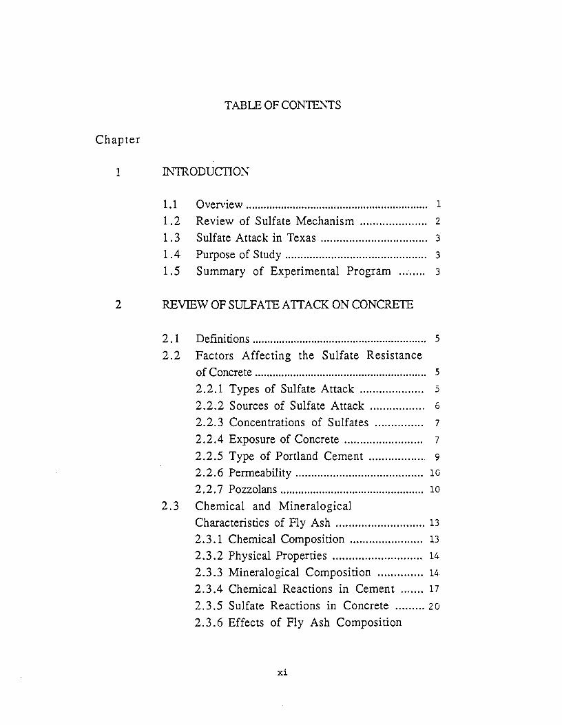
TABLE OF CON1E~7S
Chapter
1 ~~ODUCTION
1.1 Overview ..................... ............ ... .......... .......... ...... 1
1.2 Review of Sulfate Mechanism ..................... 2
1 . 3 Sulfate Attack in Texas ................... ...... ...... ... 3
1. 4 Purpose of Study .............................................. 3
1.5 Summary of Experimental Program ... '..... 3
2 REVIEWOFSULFATEATTACKONCONCRETE
2.1 Definitions ........................................................... 5
2.2 Factors Affecting the Sulfate Resistance of Concrete .......... ... ... ..... .......... .... ... ....... ........ ... .. s 2.2.1 Types of Sulfate Attack .................... s 2.2.2 Sources of Sulfate Attack ................. 6
2.2.3 Concentrations of Sulfates ............... 7
2. 2. 4 Exposure of Concrete .. .. ..... ................ 7
2.2.5 Type of Portland Cement ................. 9
2.2. 6 Permeability ......................................... 10
2.2. 7 Pozzolans ................................................ 10
2. 3 Chemical and Mineralogical Characteristics of Fly Ash ............................ 13
2. 3 .1 Chemical Composition ...... ........... ...... 13
2.3 .2 Physical Properties ............................ 14
2.3.3 Mineralogical Composition .............. 1~
2.3.4 Chemical Reactions in Cement ....... 17
2.3.5 Sulfate Reactions in Concrete ......... 20
2.3.6 Effects of Fly Ash Composition
xi
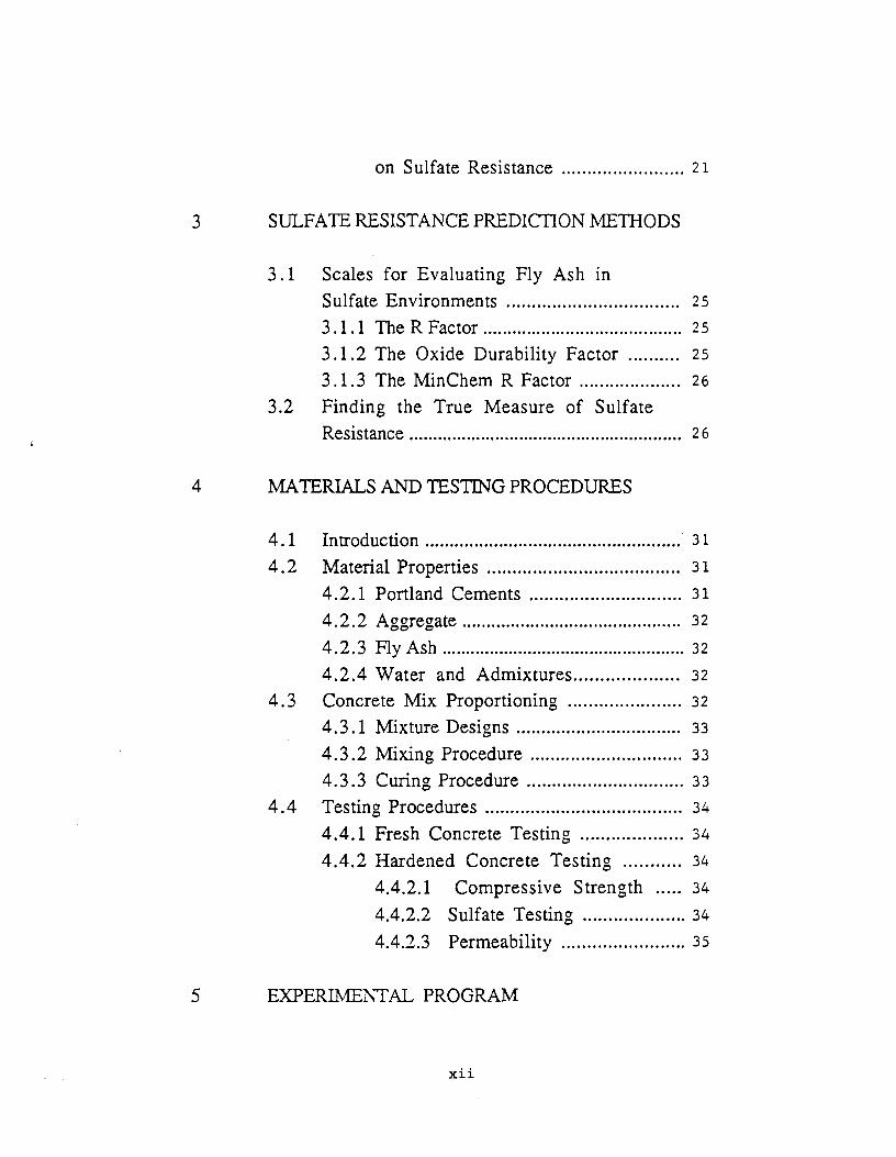
on Sulfate Resistance ........................ 21
3 SULFATE RESISTANCE PREDICTION METIIODS
3 .1 Scales for Evaluating Fly Ash in Sulfate Environments .................................. 25
3 .1.1 The R Factor ......................................... 25
3 .1.2 The Oxide Durability Factor .......... 25
3 .1.3 The MinChem R Factor .................... 26
3.2 Finding the True Measure of Sulfate Resistance . . .. . .. .. . .. .. . ... .. ... .... . .......... .. ... . . ... .. . .. .. .. 2 6
4 MATERIALS AND TESTING PROCEDURES
4. 1 Introduction .................................................... · 3 1
4 . 2 Material Properties . . . . . . . . . . .. . .. . . . . . . . . . .. . . . . . . .. .. .. 31
4.2.1 Portland Cements .............................. 31
4.2.2 Aggregate ............................................. 32
4.2.3 Fly Ash ................................................... 32
4.2.4 Water and Admixtures .................... 32
4. 3 Concrete Mix Proportioning . . . . .. .... ... ... .. . . . . 32
4.3 .1 Mixture Designs ................................. 33
4.3 .2 Mixing Procedure .............................. 33
4.3 .3 Curing Procedure ............................... 33
4.4 Testing Procedures ........... ................. ........... 34
4.4.1 Fresh Concrete Testing .................... 34
4.4.2 Hardened Concrete Testing ........... 34
4.4.2.1 Compressive Strength ..... 34
4.4.2.2 Sulfate Testing .................... 34
4.4.2.3 Permeability ........................ 35
5 EXPERIMENTAL PROGRAM
xii
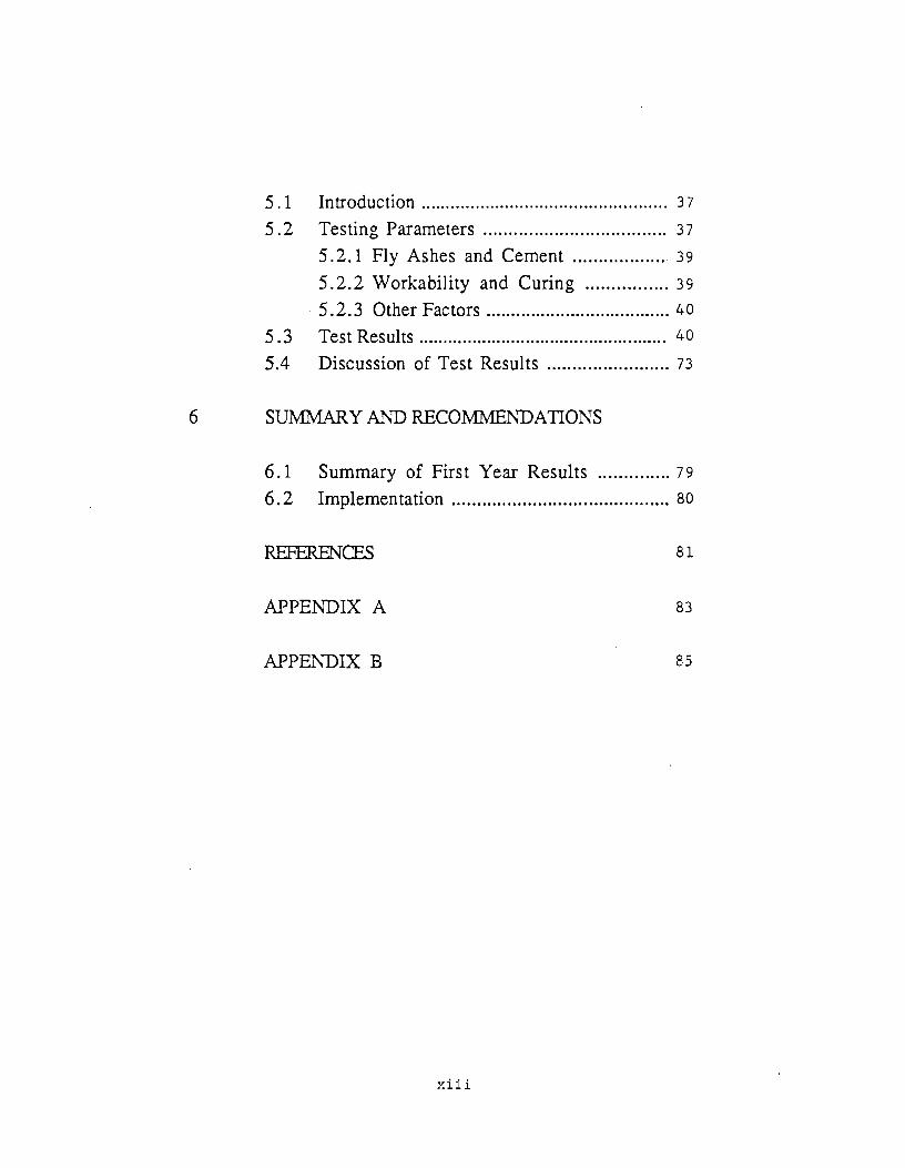
5. 1 Introduction .................................................. 3 7
5. 2 Testing Parameters .................................... 3 7
5 .2.1 Fly Ashes and Cement .................. 39
5.2.2 Workability and Curing ................ 39
5 .2.3 Other Factors ..................................... 40
5. 3 Test Results ................................................... 40
5.4 Discussion of Test Results ........................ 73
6 SUMMARY MTD RECOM::MENDATIONS
6. 1 Summary of First Year Results .............. 7 9
6.2 Implementation ........................................... 80
REFERENCES 81
APPENDIX A 83
APPEl\TDIX B 85
xiii
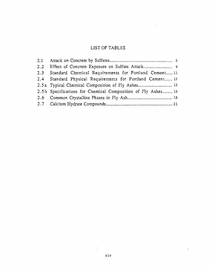
LIST OF TABLES
2.1 Attack on Concrete by Sulfates..................................................... 8
2.2 Effect of Concrete Exposure on Sulfate Attack....................... 9
2.3 Standard Chemical Requirements for Portland Cement ..... 11
2.4 Standard Physical Requirements for Portland Cement. ..... 12
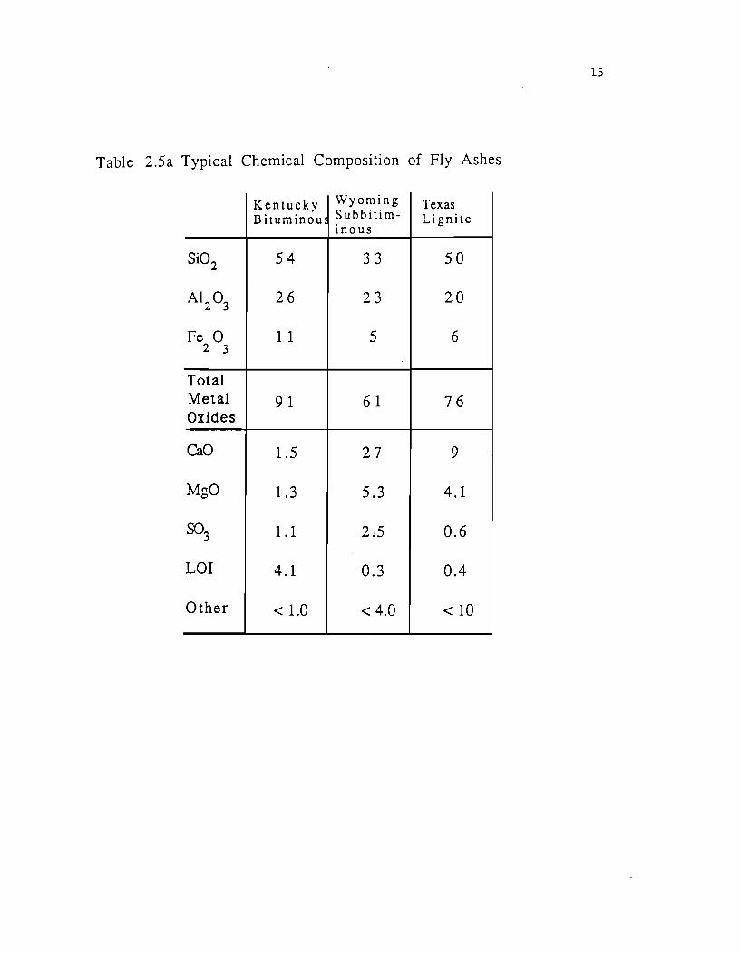
2.5 a Typical Chemical Composition of Fly Ashes ............................ 15
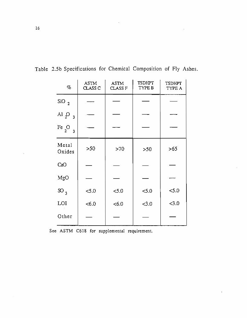
2.5b Specifications for Chemical Composition of Fly Ashes ........ 16
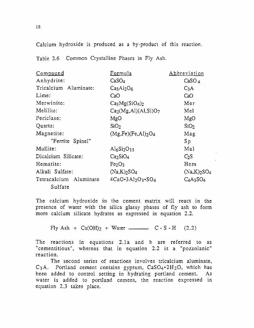
2. 6 Common Crystalline Phases in Fly Ash ..................................... 18
2. 7 Calcium Hydrate Compounds ......................................................... 21
xiv
LIST OF FIGURES
2.1 Crystalline Phase Diagram .............................................................. 22
5.1 Sulfate Test Series .............................................................................. :,s
5.2 R Factors of Study 481 Fly Ashes ................................................ 50
5.3 Oxide Durability Factors of Study 481 Fly Ashes .................. 50
5.4 The Effect of Fly Ash A on Sulfate Resistance ........................ 51
5. 5 The Effect of Fly Ash B on Sulfate Resistance ......................... 52
5. 6 The Effect of Fly Ash C on Sulfate Resistance ......................... 53
5. 7 The Effect of Fly Ash D on Sulfate Resistance ......................... 54
5. 8 The Effect of Fly Ash F on Sulfate Resistance .......................... 55
5. 9 The Effect of Fly Ash H on Sulfate Resistance ......................... 56
5. 1 0 The Effect of Fly Ash M on Sulfate Resistance ........................ 57
5.11 The Effect of Fly Ash N on Sulfate Resistance ......................... 58
5.12 The Effect of Fly Ash P on Sulfate Resistance ......................... 59
5.13 The Effect of Fly Ash R on Sulfate Resistance ......................... 60
5 .14 The Effect of Fly Ash S on Sulfate Resistance .......................... 61
5 .15 The Effect of Fly Ash T on Sulfate Resistance ......................... 62
5.16 The Effect of Fly Ash U on Sulfate Resistance ......................... 63
5.17 The Effect of Fly Ash W on Sulfate Resistance ........................ 64
5.18 Expansion of Three F1y Ashes ......................................................... 65
5.19 Expansion of Three Fly Ashes ......................................................... 65
5.20 Expansion of Concrete Containing Fly Ash T ............................. 66
5.21 Expansion of Concrete Containing Fly Ash R ............................. 66
5.22 Expansion of Concrete Containing Fly Ash D ............................. 67
5.23 Expansion of Concrete Containing Fly Ash P ............................. 67
5.24 Expansion of 3-Day Moist Cured Concrete Containing Fly
Ash B .......................................................................................................... 68
5.25 Expansion of 3-Day Moist Cured Concrete Containing Fly
Ash D .......................................................................................................... 68
XV
5 .. 26 Expansion of 3-Day Moist Cured Concrete Containing Fly
Ash P ......................................................................................................... 69
5.27 Expansion of 3-Day Moist Cured Concrete Containing Fly Ash R ......................................................................................................... 69
5. 2 8 Expansion of Control Mixes .............................................................. 7 o 5.29 Expansion of Concrete Containing Blue Circle Cement .......... 70
5. 3 0 Effect of Different Curing Times on Expansion ........................ 71
5. 3 1 Effect of Different Curing Times on Expansion ........................ 71
5. 3 2 Effect of Different Curing Times on Expansion ........................ 72
5. 3 3 Effect of Different Curing Times on Expansion ........................ 72
5.34 Mass Changes in Concrete Containing 35 Percent Fly Ash. 74
5.3 5 Mass Changes in Concrete Containing 45 Percent Fly Ash. 75
xvi
List of Photographs
5.1 Concrete Containing Type II Cement at 170 Days ................ 41
5.2 Concrete Containing 35% Fly Ash A at 56 Days ..................... 41
5.3 Concrete Containing 45% Fly Ash B at 137 Days ................... 42
5.4 Concrete Containing 45% Fly Ash C at 137 Days ................... 42
5.5 Concrete Containing 35% Fly Ash D at 165 Days ................... 43
5. 6 Concrete Containing 35% Fly Ash F at 56 Days ...................... 43
5. 7 Concrete Containing 35% Fly Ash H at 169 Days ................... 44
5. 8 Concrete Containing 35% Fly Ash M at 151 Days .................. 44
5. 9 Concrete Containing 35% Fly Ash N at 42 Days ...................... 45
5.10 Concrete Containing 35% Fly Ash P at 165 Days ................... 45
5.11 Concrete Containing 45% Fly Ash R at 151 Days ................... 46
5.12 Concrete Containing 25% Fly Ash Sat 119 Days .................... 45
5.13 Concrete Containing 25% Fly Ash T at 175 Days ................... 4 7
5.14 Concrete Containing 45% Fly Ash U at 120 Days ................... 4 7
5.15 Concrete Containing 35% Fly Ash W at 165 Days ................. 48
5.16 Comparison of Concrete Containing 25, 35 and 45 Percent
Fly Ash R ................................................................................................ 48
5.17 Comparison of Concrete Containing 25, 35 and 45 Percent
Fly Ash D ................................................................................................ 49
5.18 Four Phases of Sulfate Attack on Concrete ............................. 49
xvii
CHAPTER 1
INTRODUCTION
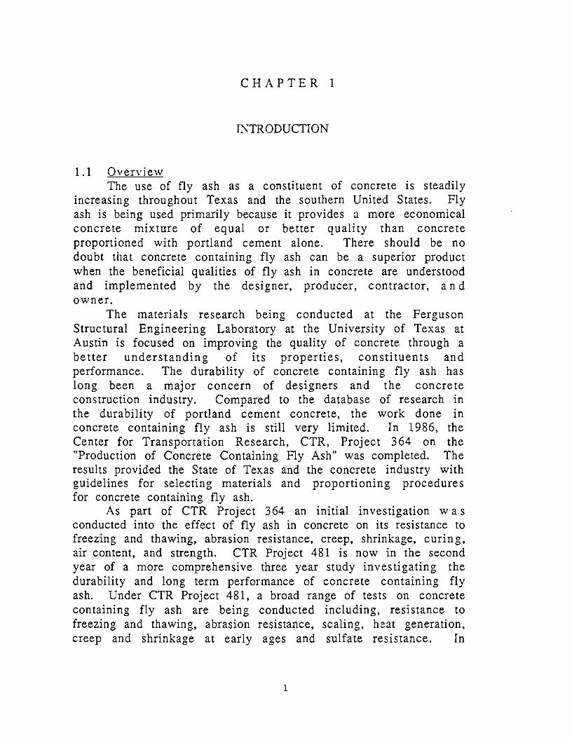
1.1 Overview The use of fly ash as a constituent of concrete is steadily
increasing throughout Texas and the southern United States. Fly ash is being used primarily because it provides a more economical concrete mixture of equal or better quality than concrete proportioned with portland cement alone. There should be no doubt that concrete containing fly ash can be a superior product when the beneficial qualities of fly ash in concrete are understood and implemented by the designer, producer, contractor, and owner.
The materials research being conducted at the Ferguson Structural Engineering Laboratory at the University of Texas at Austin is focused on improving the quality of concrete through a better understanding of its properties, constituents and performance. The durability of concrete containing fly ash has long been a major concern of designers and the concrete construction industry. Compared to the database of research in the durability of portland cement concrete, the work done in concrete containing fly ash is still very limited. In 1986, the Center for Transportation Research, CTR, Project 364 on the "Production of Concrete Containing Fly Ash" was completed. The results provided the State of Texas and the concrete industry with guidelines for selecting materials and proportioning procedures for concrete containing fly ash.
As part of CTR Project 364 an initial investigation was conducted into the effect of fly ash in concrete on its resistance to freezing and thawing, abrasion resistance, creep, shrinkage, curing, air content, and strength. CTR Project 481 is now in the second year of a more comprehensive three year study investigating the durability and long term performance of concrete containing fly ash. Under CTR Project 481, a broad range of tests on concrete containing fly ash are being conducted including, resistance to freezing and thawing, abrasion resistance, scaling, h~at generation, creep and shrinkage at early ages and sulfate resistance. In
1

2
addition, CTR Project 450 is currently in the last year of a four year program studying the effect of fly ash on alkali-silica reaction in concrete.
The durability of concrete is determined by its ability to endure its physical and environmental surroundings without losing the functional properties and structural integrity of the original design. Concrete containing fly ash can be proportioned to meet the durability requirements of a wide range of concretes, such as concrete for mass structures, pavements, structural members and high strength applications. One area where the long term performance of concrete containing high calcium fly ash has been suspect is in sulfate environments. Very little information is available on the long term performance and durability of Texas State Deparment of Highways and Public Transportation, TSDHPT, Type B or ASTM Class C (high calcium) fly ash in sulfate rich soils and groundwater or in marine environments.
Concrete in foundations, retaining walls, piers, coastal structures, chemical tanks, channels and pavements can be severely damaged by sulfate environments. To prevent any adverse chemical reaction which would reduce the service life of the concrete, a better understanding of how sulfates affect fly ash concrete is necessary.. Under the sponsorship of the Texas State Department of Highways and Public Transportation, CTR Project 481 is investigating the long term durability of concrete containing fly ash in sulfate environments.
1.2 Review of Sulfate Attack Mechanism Soluble sulfates in concrete react with calcium hydroxide
and hydrated calcium aluminates to form gypsum and calcium sulfoaluminates. The resultant compounds are more insoluble than either the calcium hydroxide or calcium aluminates and also have a greater volume. It is the increased volume that causes the degradation of concrete commonly referred to as "sulfate attack."
The precise chemical mechanism of expansion is still not clearly understood but through a series of chemical reaction, ettringite is formed in concrete subjected to sulfates. The ettringite has a solid volume of about 2.5 times that of the initial hydration products [10]. What is clearly understood is that expansions occur in concrete during the sulfate attack process and the integrity of the concrete is damaged.

3
1. 3 Sulfate Attack in Texas The state of Texas has two primary areas where sulfate
resistant concrete is needed. Scattered throughout west Texas are many areas of sulfate rich soils that are in contact with bridge piers, building foundations, and retaining structures. Also, along the coastal region from Louisiana to Mexico, there are many piers, marine facilities and seawalls that are exposed to sulfates in the seawater of the Gulf of Mexico. Concrete placed in these regions may exhibit very poor long term performance if it is not proportioned to resist moderate to severe sulfate exposures.
Texas fly ashes are typically high calcium fly ash collected from burning subbituminous coals from Wyoming and Montana or low calcium fly ash from Texas lignite coals. When these fly ashes are used in concrete exposed to moderate sulfate environments, the long term performance and serviceability of the concrete is uncertain.
1.4 Purpose of Study This study on sulfate attack on concrete containing fly ash
under CTR Project 481 is being conducted to assess the effect of fly ash on concrete exposed to sulfate environments. The resulting information will be used to propose guidelines for selecting materials and proportioning concrete containing fly ash in sulfate rich environments.
1.5 Summarv of Experimental Program
The experimental program consists mainly of monitoring the expansions and changes in mass of concrete specimens soaking in 10% Na2S 04. In order to better understand why some specimens expand and deteriorate and other do not, a series of quantitative tests are being performed on the concrete and fly ashes used as the study progresses. These quantitative tests include the chemical and physical analysis of the fly ashes and other concrete materials, X-Ray Diffraction on the fly ash to determine the crystalline phases that are present, petrographic analysis of the concrete specimens to determine the extent of deterioration, 10n permeability of concrete and periodic physical inspection of the specimens.
4
At the conclusion of this study, the information collected from this research will be used to develop guidelines for selecting fly ash for use in concrete exposed to sulfate environments.
CHAPTER 2
REVIEW OF SULFATE ATIACK IN CONCRETE
2.1 Definitions The following definitions of terms have been adopted m this
report:
Calcium Silicate Hydrate: Any of the various reaction products of calcium silicate and water. which provide the strongest binding force between particles. E ttri n gi te: A mineral, high sulfate calcium sulfoaluminate; occurring in nature ofr formed by sulfate attack on mortar and concrete; the product of the principal expansion-producing reaction in expansive cements. Fly Ash: Finely divided residue resulting from the combustion of ground or powdered coal and which is transported from the furnace by flue gases. Free Lime: Unhydrated calcium oxide which has not combined with silica, alumina or ferrite during the formation of cement or fly ash. Qypsum: A mineral having the composition; calcium sulfate dihydrate. Hydrogarnet: Any of a group of crystalline phases containing hydrated silicates and a combination of iron, aluminum, or magnus1um. Monosulfoaluminate: Calcium sulfoaluminate hydrate. Portland Cement: A hydraulic cement cons1stmg of pulverized hydraulic calcium silicates and usually containing some form of calcium sulfate.
2.2 Factors Affecting the Sulfate Resistance of Concrete 2.2.1 Tvpes of Sulfate Attack. Sulfates are found in several
forms in concrete. These sulfates can be divided into two categories, soluble sulfates and sulfates in seawater. Sulfates in either category may contribute to sulfate attack, but the
5
6
concentrations and degree of degradation between the two constitutes the main distinction.
Soluble sulfates are sulfates which are present as a result of the dissolution of salts, such as sodium sulfate, potassium sulfate, magnesium sulfate or calcium sulfate. The sulfate ions in solution are available to combine with compounds of hydrated portland cement to form other compounds containing sulfate. The sulfate containing compounds often have a greater volume than the original portland cement hydrates.
Seawater contains soluble sulfates as described above, however seawater also contains many other salts which are not sulfate based. For reasons which are not yet clearly understood, the presence of ions from other salts slows the formation of expansive compounds containing sulfates, thereby moderating the volumetric changes associated with the formation of ettringite.
:Magnesium sulfates are a special group among the soluble sulfates. The magnesium reacts with the hydroxide in the pore water solution to form magnesium hydroxide. As the hydroxide ions are depleted the calcium silicate hydrate binder begins to degrade causing a loss in strength along with the formation of expansive sulfate compounds. Over long periods of exposure, the magnesium hydroxide will form an impermeable layer and prevent further sulfate intrusion. This protective coating may or may not form before the concrete is deemed unserviceable.
2.2.2 Sources of Sulfate Attack. A major problem in providing protection against sulfate attack is determining where problem areas lie. Over 90 percent of the concrete placed in the United States is not subjected to sulfate environments[1]. But determining the location of the less than 10 percent of concrete which is subjected to sulfate attack is difficult. Frequently, sulfates occur in high concentrations in small localized zones. The sulfates may be in soil layers or in the groundwater surrounding a structure.
Although some areas can be clearly detected as sulfate environments the localized high concentrations often lead to unsuspected damages. Concrete in foundations, slabs on grade, canals and pipelines may suffer distress from sulfate rich groundwater or soils. Harboe (1] points out that there are three
7
choices for the designer m areas with localized sulfate environments:
1. very extensive soil and groundwater testing, 2. construct the entire project with sulfate resistant
concrete, or
3. construct the entire project with moderately sulfate resistant concrete and replace isolated sections of concrete when sulfate damage is detected.
All three options can be expensive. Extensive testing for sulfates may lead to no assurance that sulfates will not be present in the groundwater several years after the completion of the project. The use of Type V cement is very expensive and may not even be available. Lastly, repairs of underground structures can be both expensive and inconvenient.
Seawater contains relatively large amounts of magnesiUm and calcium· sulfates. However the severity of sulfate attack from seawater is diminished by the presence of other salts in solution. Seawater is not considered as a severe condition but rather as a moderate sulfate environment. Coastal and offshore structures should be designed with moderate sulfate resistant concrete.
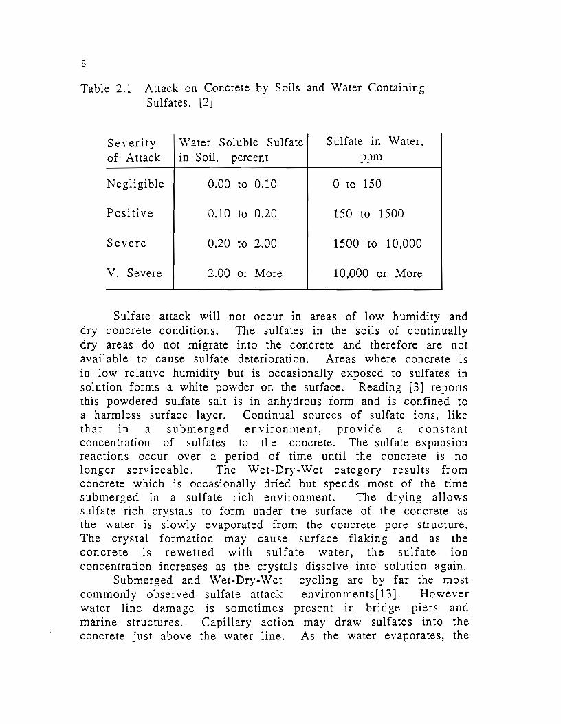
2.2.3 Concentrations of Sulfates. The relative degree of sulfate attack on concrete depends on the sulfate ion concentration in the water or soil. Table 2.1 indicates the level of sulfate attack that should be expected under different sulfate concentrations.
The United States Bureau of Reclamation (USBR) recommends Type I cement where the sulfate concentration is negligible, Type II or equal in positive environments and Type V or equal in severe and very severe sulfate environment. The highest concentrations reported by the USBR were in the White Wood Creek Bridge in South Dakota. Concentration of 9900 ppm were reported shortly before the bridge columns were replaced because of severe sulfate damage[l].
2.2.4 Exposure of Concrete. In addition to the concentration of sulfates, the nature of the concrete environment is important in determining the severity of the concrete degradation. Table 2.2 lists four major physical exposure conditions and the degradation associated with each.
8
Table 2.1 Attack on Concrete by Soils and Water Containing Sulfates. [2]
Severity Water Soluble Sulfate Sulfate in Water, of Attack in Soil, percent ppm
Negligible 0.00 to 0.10 0 to 150
Positive 0.10 to 0.20 150 to 1500
Severe 0.20 to 2.00 1500 to 10,000
V. Severe 2.00 or More 10,000 or More
Sulfate attack will not occur in areas of low humidity and dry concrete conditions. The sulfates in the soils of continually dry areas do not migrate into the concrete and therefore are not available to cause sulfate deterioration. Areas where concrete is in low relative humidity but is occasionally exposed to sulfates in solution forms a white powder on the surface. Reading [3] reports this powdered sulfate salt is in anhydrous form and is confined to a harmless surface layer. Continual sources of sulfate ions, like that m a submerged environment, provide a constant concentration of sulfates to the concrete. The sulfate expansion reactions occur over a period of time until the concrete is no longer serviceable. The Wet-Dry-Wet category results from concrete which is occasionally dried but spends most of the time submerged in a sulfate rich environment. The drying allows sulfate rich crystals to form under the surface of the concrete as the water is slowly evaporated from the concrete pore structure. The crystal formation may cause surface flaking and as the concrete 1s rewetted with sulfate water, the sulfate ion concentration increases as the crystals dissolve into solution again.
Submerged and Wet-Dry-Wet cycling are by far the most commonly observed sulfate attack environments[13]. However water line damage is sometimes present in bridge piers and marine structures. Capillary action may draw sulfates into the concrete just above the water line. As the water evaporates, the

9
sulfate concentration continues to increase until the cry s t a 1 s progressively flake off the concrete cover.
Table 2.2 Effect of Concrete Exposure on Sulfate Attack Mechanism.
Exposure Condition Severity of Attack
Always Dry Negligible
Dry - Wet - Dry Mild Surface Damage
Always Wet" Continual Degradation
Wet - Dry - Wet Accelerated Degradation
2.2.5 Tvpe of Portland Cement. The type of portland cement used in concrete exposed to sulfate environments is certainly one of the primary considerations in determining the resistance of concrete to sulfate attack. Since sulfate expansion is often caused by the formation of alumina hydrates, the reduction of alumina in the cement leads to a more sulfate resistant portland cement.
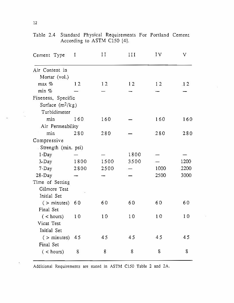
The American Society of Testing and Materials (ASTM) classifies portland cement into five classes. The standard chemical and physical requirements of these classes are shown in Tables 2.3 and 2.4 respectively. ASTM Type III cement is a high early strength cement while ASTM Type IV cement is a low heat of hydration cement. Neither of these portland cements adds to the sulfate resistance of concrete and therefore will not be addressed herein.
ASTM Type I portland cement is the most common cement used in the concrete industry. Type I cement is widely available throughout the United States and is the least expensive of the five classes of portland cement. The ASTM Standard Specification Cl50, places no direct limit on the amount of tricalcium aluminate, C3A, in Type I cement. Typical C3A contents for Type I cement
10
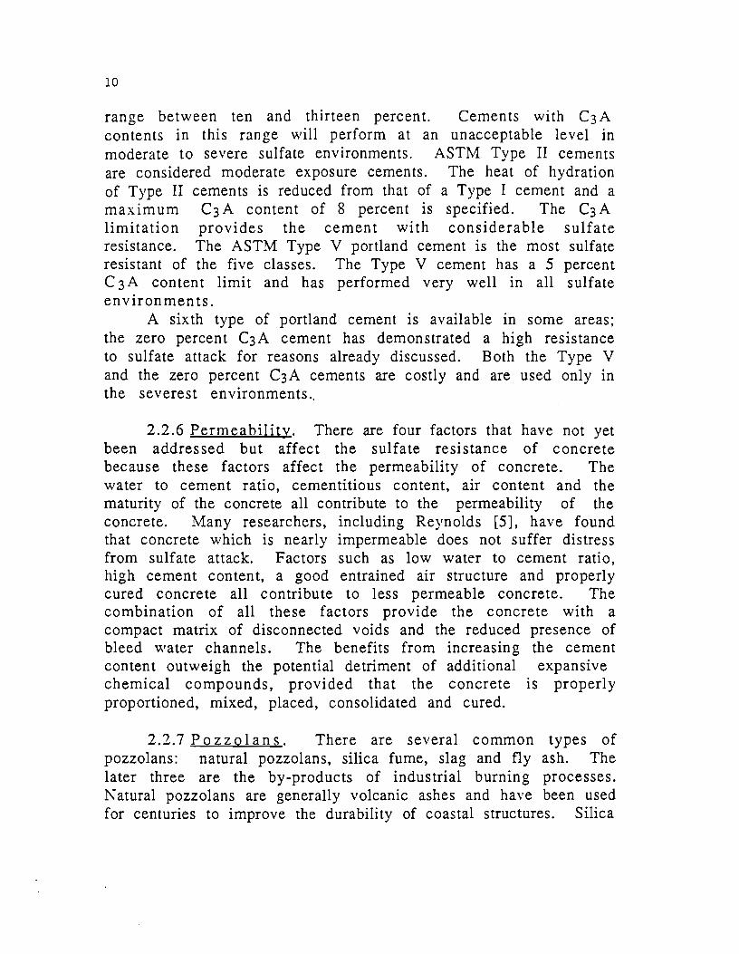
range between ten and thirteen percent. Cements with C3 A contents in this range will perform at an unacceptable level in moderate to severe sulfate environments. ASTM Type II cements are considered moderate exposure cements. The heat of hydration of Type II cements is reduced from that of a Type I cement and a maximum C3A content of 8 percent is specified. The C3A limitation provides the cement with considerable sulfate resistance. The ASTM Type V portland cement is the most sulfate resistant of the five classes. The Type V cement has a 5 percent C 3A content limit and has performed very well in all sulfate environments.
A sixth type of portland cement is available in some areas; the zero percent C3A cement has demonstrated a high resistance to sulfate attack for reasons already discussed. Both the Type V and the zero percent C3A cements are costly and are used only in the severest environments ..
2.2.6 Permeability. There are four factors that have not yet been addressed but affect the sulfate resistance of concrete because these factors affect the permeability of concrete. The water to cement ratio, cementitious content, air content and the maturity of the concrete all contribute to the permeability of the concrete. Many researchers, including Reynolds [5], have found that concrete which is nearly impermeable does not suffer distress from sulfate attack. Factors such as low water to cement ratio, high cement content, a good entrained air structure and properly cured concrete all contribute to less permeable concrete. The combination of all these factors provide the concrete with a compact matrix of disconnected voids and the reduced presence of bleed water channels. The benefits from increasing the cement content outweigh the potential detriment of additional expansive chemical compounds, provided that the concrete is properly proportioned, mixed, placed, consolidated and cured.
2.2. 7 Po z z o 1 an s. There are several common types of pozzolans: natural pozzolans, silica fume, slag and fly ash. The later three are the by-products of industrial burning processes. Nat ural pozzolans are generally volcanic ashes and have been used for centuries to improve the durability of coastal structures. Silica

11
Table 2.3 Standard Chemical Requirements for Portland Cement According to ASTM C150 [4].
Cement Type I I I III IV v
Si02 (min%) 20
Ab03 (max%) 6.0
Fe203 (max %) 6.0 6.5 MgO (max%) 6.0 6.0 6.0 6.0 6.0
S03 (max%)
C3A~8% 3.0 3.0 3.5 2.3 2.3
C3A> 8% 3.5 4.5
LOI (max%) 3.0 3.0 3.0 2.5 3.0
Insoluble Res.
(max%) 0.75 0.75 0.75 0.75 0.75
C3S (max%) 35
C2S (min%) 40
C3A (max%) 8 15 7 5
~AF+C2F
(max%) 25
See appendix A for chemical notation. Additional Requirements are stated in ASTM C150 Table 1 and lA.
12
Table 2.4 Standard Physical Requirements For Portland Cement According to ASTM C150 [4].
Cement Type
Air Content in
Mortar (vol.)
max%
min%
I
1 2
Fineness, Specific
Surface (m2fkg)
Turbidimeter
mm 160
Air Permeability
mm 280
Compressive
Strength (min. psi)
1-Day
3.-Day
7-Day
28-Day
Time of Setting
Gilmore Test
Initial Set
1800
2800
( > minutes) 6 0
Final Set
(<hours) 1 0
Vicat Test
Initial Set
( > minutes) 4 5
Final Set
( < hours) 8
I I
12
160
280
1500
2500
60
10
45
8
I I I
12
1800
3500
60
10
45
8
IV
1 2
160
280
1000
2500
60
1 0
45
8
Additional Requirements are stated in ASTM Cl50 Table 2 and 2A.
v
12
160
280
1200
2200
3000
60
10
45
8
13
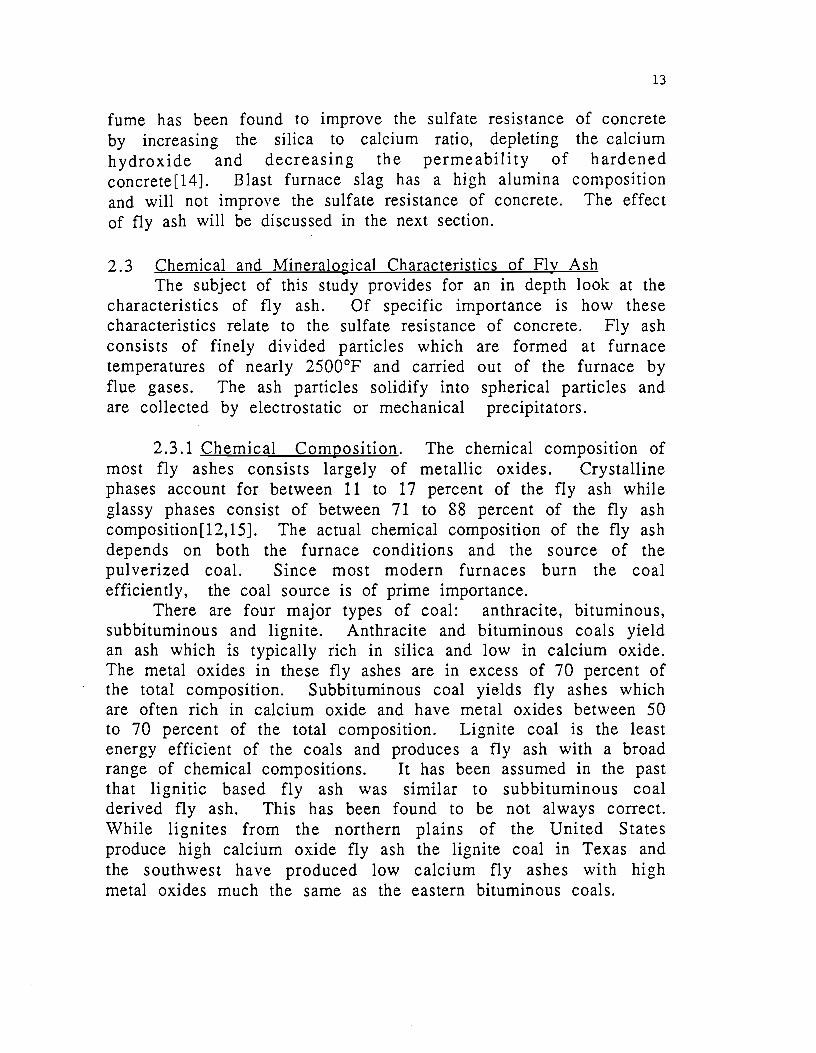
fume has been found to improve the sulfate resistance of concrete by increasing the silica to calcium ratio, depleting the calcium hydroxide and decreasing the permeability of hardened concrete[14]. Blast furnace slag has a high alumina composition and will not improve the sulfate resistance of concrete. The effect of fly ash will be discussed in the next section.
2.3 Chemical and Mineralo~icaJ Characteristics of Flv Ash The subject of this study provides for an in depth look at the
characteristics of fly ash. Of specific importance is how these characteristics relate to the sulfate resistance of concrete. Fly ash consists of finely divided particles which are formed at furnace temperatures of nearly 2500°F and carried out of the furnace by flue gases. The ash particles solidify into spherical particles and are collected by electrostatic or mechanical precipitators.
2.3.1 Chemical Composition. The chemical composition of most fly ashes consists largely of metallic oxides. Crystalline phases account for between 11 to 17 percent of the fly ash while glassy phases consist of between 71 to 88 percent of the fly ash composition[12, 15]. The actual chemical composition of the fly ash depends on both the furnace conditions and the source of the pulverized coaL Since most modern furnaces burn the coal efficiently, the coal source is of prime importance.
There are four major types of coal: anthracite, bituminous, subbituminous and lignite. Anthracite and bituminous coals yield an ash which is typically rich in silica and low in calcium oxide. The metal oxides in these fly ashes are in excess of 70 percent of the total composition. Subbituminous coal yi~lds fly ashes which are often rich in calcium oxide and have metal oxides between 50 to 70 percent of the total composition. Lignite coal is the least energy efficient of the coals and produces a fly ash with a broad range of chemical compositions. It has been assumed in the past that lignitic based fly ash was similar to subbituminous coal derived fly ash. This has been found to be not always correct. While lignites from the northern plains of the United States produce high calcium oxide fly ash the lignite coal in Texas and the southwest have produced low calcium fly ashes with high metal oxides much the same as the eastern bituminous coals.

14
Tables 2.5a and b shows the typical compositiOn of fly ash from different sources and the ASTNI and TSDHPT criteria for classifying the fly ash. The chemical composition of fly ash is similar to that of burnt clay, high in alumina and iron oxides[9]. The silica and alumina seem to have the greatest influence on the pozzolanic activity whereas the calcium oxide content contributes to the cementitious properties of the fly ash.
The sulfate resistance of concrete containing fly ash has been hypothesized by Dunstan [2] to be related to the calcium oxide content of the fly ash over 5 percent and inversely related to the iron oxide content of the fly ash. The 5 percent is used as an average for the crystalline lime content in fly ash which is believed not to participate in the sulfate attack problem. Other investigators believe the silica and alumina contents also contribute to the sulfate resistance of the concrete containing fly ash [6,7 ,8]. The other chemical compound which contributes to the sulfate resistance of concrete is the sulfate content of the fly ash. The sulfate is present in fly ash as anhydrite, gypsum or in glass and is measured as sulfur trioxide, S03. When the S03 content is high, the mortar is effectively supersulfated and hardens in an expanded form[6]. The expanded form of the concrete is protected from deterioration due to sulfate expansion.
2.3.2 Phvsical Characteristics of Fly Ash. There are two physical properties of fly ash which need to be addressed briefly. Fineness and pozzolanic activity both contribute to the effect of fly
·ash on concrete. The pozzolanic activity has no direct effect on the sulfate resistance of concrete but is a measure of the materials ability to react with calcium hydroxide to form compounds which have cementing properties. The fineness of fly ash has long been recognized as an important factor in the strength gain of fly ash -portland cement concrete. Although fly ash fineness is difficult to measure consistently, finer fly ash reacts more thoroughly and reduces the permeability of the mortar matrix within the concrete.
2.3.3 :Mineralo~ical Characteristics of Flv Ash. Fly ash is composed of nearly 15 percent crystalline material. The
15
Table 2.5a Typical Chemical Composition of Fly Ashes
Kentucky Wyoming Texas Bituminous Subbitim- Lignite
1nous
Si02 54 3 3 50
Al2
03
26 23 20
Fe 0 1 1 5 6 2 3
Total Metal 9 1 6 1 76 Oxides
CaO 1.5 27 9
MaO 0 1.3 5.3 4.1
so3 1.1 2.5 0.6
LOI 4.1 0.3 0.4
Other < 1.0 < 4.0 < 10
16
Table 2.5b Specifications for Chemical Composition of Fly Ashes.
ASTM ASTM TSDHPT TSDHPT % Cl..ASSC Cl..ASS F TYPEB TYPE A
SiO 2 - - - -
Al20 - - - -3
Fe 0 - - - -2 3
Metal >50 >70 >65 Oxides >50
CaO - - - -
MgO - - - -
ro3 <5.0 <5.0 <5.0 <5.0
LOI <6.0 <6.0 <3.0 <3.0
Other - - - -
See ASTM C618 for supplemental requirement.

17
remammg material in fly ash is glassy in nature. The crystalline material can be readily identified by X-Ray diffraction analysis and quantified through the use of known standards. Table 2.6 lists the most common crystalline phases found in fly ash and their corresponding chemical composition [ 15].
The mineralogical composition of fly ash was determined by Watt and Thorne [9] and has been related to the sulfate attack mechanism by Mehta [7]. ASTM Class F fly ashes from bituminous sources commonly contain four crystalline phases: quartz, mullite, hematite and magnetite. ASTM Class C fly ashes from subbituminous sources typically contain the same four phases plus several additional crystalline materials such as: anhydrite, tricalcium aluminate (C3A), crystalline lime, merwinite, melilite, periclase, and dicalcium silicate (C2S). With the exception of anhydrite, lime, C3A and C2S, these crystalline materials are nonhydraulic.
The silica, alumina and iron oxide in the glassy spheres of the fly ash react with lime to form hydrate compounds which contribute to the long term strength of the concrete. This reaction is referred to as a pozzolaanic reaction. The C3 A crystalline phase of the fly ash may be a major mineralogical influence in the sulfate attack mechanism. Se .reral research studies are now under way to better understand the relationship between fly ash composition and sulfate resistance and to quantify the results to predict the effect of fly ash on the sulfate resistance of concrete con~aining fly ash.
2.3.4 Chemistry of Cement. The chemical reactions of both portland cement and fly ash are very complex. The chemical shorthand notation used in this section is that commonly used in cement chemistry and is defined in appendix A, Table A-1. The first is the reaction that takes place in portland cement to form the binding characteristics of concrete. Equations 2.1 a and b express the formation of calcium silicate hydrates from either tricalcium silicate or dicalcium silicate and water. Calcium silicate hydrates, C-S-H, are the compounds that provide the binding qualities of portland cement concrete.
C - S - H + Ca(OH)2 (2.1 a)
C - S - H + Ca(OH)z (2.1 b)
18
Calcium hydroxide is produced as a by-product of this reaction.
Table 2.6 Common Crystalline Phases m Fly Ash.
CQm;QQund Formula Abbreviation Anhydrite: CaS04 CaS04 Tricalcium Aluminate: Ca3Al206 C3A Lime: CaO CaO Merwinite: Ca3Mg(Si04)2 Mer Melilite: Ca2(Mg,Al)(Al,Si)07 Mel Periclase: MgO MgO Quartz: Si02 Si02 Magnetite: (Mg,Fe)(Fe,Al)204 Mag
"Ferrite Spinel" Sp Mullite: Al6Si2013 Mul
Dicalcium Silicate: Ca2Si04 c2s Hematite: Fe203 Hem
Alkali Sulfate: (Na,K)2S04 (Na,K)2S04
Tetracalcium Aluminate 4Ca0•3Al203•S04 C¢3S04 Sulfate
The calcium hydroxide in the cement matrix will react in the presence of water with the silica glassy phases of fly ash to form more calcium silicate hydrates as expressed in equation 2.2.
Fly Ash + Ca(OH)2 + Water C- S - H (2.2)
The reactions in equations 2.1 a and b are referred to as "cementitious ", whereas that in equation 2.2 is a "pozzolanic" reaction.
The second series of reactions involves tricalcium aluminate, C3A. Portland cement contains gypsum, CaS04•2H20, which has been added to control setting in hydrating portland cement. As water is added to portland cement, the reaction expressed in equation 2.3 takes place.
19
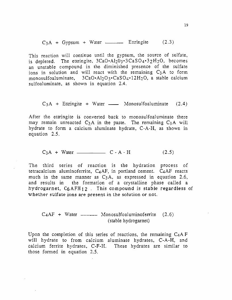
C3A + Gypsum + Water Ettringite (2.3)
This reaction will continue until the gypsum, the source of sulfate, is depleted. The ettringite, 3CaO•Al203•3CaS04·3zHzO, becomes an unstable compound in the diminished presence of the sulfate ions in solution and will react with the remaining C3 A to form monosulfoaluminate, 3CaO•Alz03•CaS04•12HzO, a stable calcium sulfoaluminate, as shown in equation 2.4.
C3A + Ettringite + Water Monosulfoaluminate (2.4)
After the ettringite is converted back to monosulfoaluminate there may remain unreacted C3A in the paste. The remaining C3A will hydrate to form a calcium aluminate hydrate, C-A-H, as shown in equation 2.5.
C-A-H (2.5)
The third series of reaction is the hydration process of tetracalcium aluminoferrite, C4AF, in portland cement. C4AF reacts much in the same manner as C3A, as expressed in equation 2.6, and results in the formation of a crystalline phase called a hydrogarnet, C6 AFH 12 . This compound is stable regardless of whether sulfate ions are present in the solution or not.
C4AF + Water ------ Monosulfoaluminoferrite (2.6) (stable hydrogarnet)
Upon the completion of this series of reactions, the remaining C4A F will hydrate to from calcium aluminate hydrates, C-A-H, and calcium ferrite hydrates, C-F-H. These hydrates are similar to those formed in equation 2.5.
20
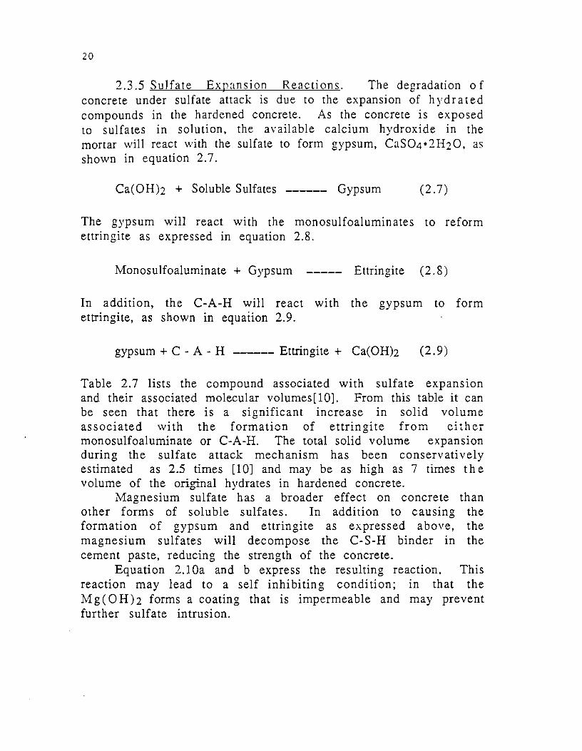
2.3.5 Sulfate Expansion Reactions. The degradation of concrete under sulfate attack is due to the expansion of hydrated compounds in the hardened concrete. As the concrete is exposed to sulfates in solution, the available calcium hydroxide in the mortar will react with the sulfate to form gypsum, CaS04•2H20, as shown in equation 2. 7.
Ca(OH)2 + Soluble Sulfates ------ Gypsum (2.7)
The gypsum will react with the monosulfoaluminates to reform ettringite as expressed in equation 2.8.
Monosulfoaluminate + Gypsum Ettringite (2.8)
In addition, the C-A-H will react with the gypsum to form ettringite, as shown in equation 2.9.
gypsum + C - A - H ------ Ettringite + Ca(OH)2 (2.9)
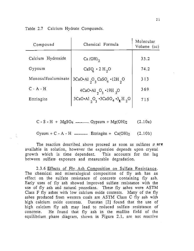
Table 2.7 lists the compound associated with sulfate expansion and their associated molecular volumes [ 1 0]. From this table it can be seen that there is a significant increase m solid volume associated \Vith the formation of ettringite from either monosulfoaluminate or C-A-H. The total solid volume expansion during the sulfate attack mechanism has been conservatively estimated as 2.5 times [ 1 0] and may be as high as 7 times the volume of the original hydrates in hardened concrete.
~1agnesium sulfate has a broader effect on concrete than other forms of soluble sulfates. In addition to causing the formation of gypsum and ettringite as expressed above, the magnesium sulfates will decompose the C-S-H binder in the cement paste, reducing the strength of the concrete.
Equation 2.1 Oa and b express the resulting reaction. This reaction may lead to a self inhibiting condition; in that the M g ( 0 H) 2 forms a coating that is impermeable and may prevent further sulfate intrusion.
21
Table 2. 7 Calcium Hydrate Compounds.
Compound Chemical Formula Molecular Volume (cc)
Calcium Hydroxide Ca (0H)2 33.2
Gypsum casq • 2 H 20 74.2
Monosulfoaluminate 3Ca0•Al 0 CaS04 •12H 0 313 2 3 2
C-A-H 4Ca0•Al2 0
3 •19H
20 369
Ettringite 3CaO•Al 2 0
3 •3CaSO 4 •3!. H
2 0 715
C - S - H + MgS04 --- Gypsum + Mg(OH)2 (2.10a)
Gysum + C - A - H ---- Ettringite + Ca(OH)2 (2.10b)
The reaction described above proceed as soon as sulfates <3 are available in solution, however the expansion depends upon crystal growth which is time dependent. This accounts for the lag between sulfate exposure and measurable degradation.
2.3.6 Effects of Flv Ash Composition on Sulfate Resistance. The chemical and mineralogical composition of fly ash has an effect on the sulfate resistance of concrete containing fly ash. Early uses of fly ash showed improved sulfate resistance with the use of fly ash and natural pozzolans. These fly ashes were ASTM Class F fly ashes with low calcium oxide contents. Many of the fly ashes produced from western coals are ASTM Class C fly ash with high calcium oxide contents. Dunstan [2] found that the use of high calcium fly ash may lead to reduced sulfate resistance of concrete. He found that fly ash in the mullite field of the equilibrium phase diagram, shown in Figure 2.1, are not reactive

22
with sulfates in solution and therefore do not form ettringite when exposed to sulfates. The mullite rich fly ashes are characterized by low calcium contents; bringing about the conclusion that a low calcium content in fly ash is beneficial to sulfate resistance.
Fig. 2.1 Equilibrium Phase Diagram.
Dunstan also suggests that, based on Kalousek's work [11], iron rich ettringite crystals grow very slowly or not at all in the presence of sulfate ions in solution. From this he associates the presence of iron oxide in fly ash as beneficial to the sulfate resistance of concrete.
Calcium silicate hydrates formed through pozzolanic reactions have a lower calcium-silica ratio than those formed from the cementitious reaction of portland cement. This reduction allows magnesium, alkalies, sulfates and alumina to occupy a position in the lattice of the calcium silicate hydrate, thereby making them unavailable to expansive compounds [12].
The use of bulk chemical analysis is not sufficient to classify fly ash for use in predicting their effect on concrete subjected to sulfate exposures. Many of the crystalline phases in fly ash are unavailable to either the pozzolanic reaction or the sulfate
23
reactions. In some cases C3 A in fly ash may promote sulfate attack while S03 may act to supersulfate the mixture, making it more resistant to sulfate attack.
In addition, Lea[lO] points out that low calcium pozzolans use the calcium hydroxide from the portland cement hydration, reducing the amount of calcium hydroxide available for the formation of gypsum. The complete effect of fly ash on the sulfate resistance of concretes is not fully understood at this time, however the dominant factors are being identified and analyzed.

CHAPTER 3
SULFATE RESITANCE PREDICTION :METIIODS
3.1 Methods for Evaluating Fly Ash for Sulfate Attack. There have been several methods developed in recent years
to evaluate the performance of fly ash in concrete subjected to sulfate environments. None of these methods have been accurate for predicting the behavior of a broad range of portland cement and fly ash combinations. Each of the methods discussed in this section have merit in their conception but fail to encompass all the factors involved, some of which are still not clearly understood.
3.1.1 The R Value. This simple factor was proposed by Dunstan of the United States Bureau of Reclamation for use in their specifications [2]. He later proposed this factor for broader use. The R factor is based on the calcium-silicate-aluminate equilibrium phase diagram. As discussed in the previous chapter, Dunstan found the total calcium oxide and iron oxide contents to be important factors in the expansion of concrete containing fly ash in sulfate solution. His proposed factor. equation 3.1, has been the subject of controversy because it disallows almost all ASTM Class C fly ashes by emphasizing calcium oxide content and not taking into account factors such as the S03 content, mineralogical considerations, replacement levels of fly ash, and portland cement properties.
R = CaO (%) - 5 Fe203 (%)
(3.1)
A later paper by Dunstan on sulfate resistance [16] addressed the amount of fly ash used in the form of another factor called the Rv factor but this concept has not taken hold in the technical community because of lack of research evidence.
3 .1.2 Oxide Durabilitv Factor. The OD factor was proposed by Hartmann and Mangotich of the Western Institute of Technology [8]. This factor, expressed in equation 3.2, uses the chemical properties of both the portland cement and the fly ash to calculate
25

26
the resistance of concrete to sulfate attack. This factor also incorporates the level of replacement by weighting the chemical composition according to its replacement level.
OD Factor = Total CaO (%) * Free Lime (%)
Si02 (%) + Al203 (%) + Fe203 (%) (3.2)
Hartmann and J..1angotich found a relationship between the free lime content of the cementitious material and the sulfate resistance of concrete containing fly ash. In addition, they included all the metallic oxides in the prediction formula, but they
did not consider the importance of the crystalline phases of the fly ash.
3.1.3 MinChem R Factor. This is the newest of the rating systems and it is still under development by Manz at the University of North Dakota [6]. The theory behind this factor is credited to P. K. Mehta. This more complicated factor expressed in equation 3.3, uses both the mineralogical and chemical characteristics of a fly ash to determine its resistance to. sulfate attack.
J..1inChem R Factor = f(Si02, Al203, Fe203, CaO, S03, Lime, Anhydrite, C2S, C3A, Hematite, Mullite, Spinel Ferrite) (3 .3)
The proposed MinChem R factor has two components. The first component, the "calcium aluminate potential", is a function of the metallic oxides, total CaO content and the crystalline phases: quartz, mullite, ferrite spinel, hematite, melilite, merwinite, lime and dicalcium silicate found in fly ash. The second component of the equation, the "calcium sulfate equivalent", is a function of the anhydrite and S03 contents of the fly ash.
3.2 Finding the True Measure of Sulfate Resistance The development of equations such as the R factor, the OD
factor and the J..1inChem R factor has not yet produced a meaningful, reliable means for predicting the performance of concrete containing fly ash in sulfate environments. The small pool of available information on the performance of high calcium fly ash in concrete is the primary reason for the slow progress.
27
The research completed up to now has made substantial contributions in isolating several important variables that either contribute to or detract from the sulfate resistance of concrete containing fly ash. These variables include certain physical concrete properties such as permeability, strength and maturity of the concrete at the time it is exposed to the sulfate environment. Other variables that are independent of the exposure and physical condition of the concrete include the chemical, physical and mineralogical characteristics of the cementitious and pozzolanic materials.
The physical characteristics of the fly ash and cement are important to the extent that they affect the permeability of the concrete. However the effects of the chemical and mineralogical composition of these materials are not clearly understood. Yet the prediction equations are all based on these properties.
The sulfate-resistance prediction equations developed up to now do not provide an adequate assessment of the concrete. In some cases where good performance in the field is observed the equations predict failure. In other cases, poor performance results from fly ashes which are predicted to yield sulfate resistant . concrete. For this reason TSDHPT Project 481 is investigating a broad spectrum of prediction criteria for the sulfate resistance of concrete containing fly ash.
The first component of the binder that is widely recognized as a detrimental factor in the sulfate resistance of fly ash concrete is calcium. Calcium hydroxide in the hardened concrete reacts with sulfates to form gypsum and start the expansive series of reactions. Free lime in fly ash is thought by some to be of some significance in the sulfate resistance equations. However, hardburned crystalline lime is very dense and reacts very slowly with moisture whereas free lime in portland cement and fly ash is consumed in the early hydration of portland cement. The R factor does not consider free lime, but rather uses the total CaO content of the fly ash as a detriment to sulfate resistance. The OD factor considers the combined total CaO content and the free lime content over 1.0 percent of both the cement and fly ash as detrimental to the sulfate resistance. The MinChem R factor subtracts out the crystalline free lime from the total CaO content of the fly ash and considers the remainder as detrimental to the sulfate resistance of concrete containing fly ash.
28
Calcium hydroxide is present in most hardened concrete. It is necessary for the formation of C-S-H through the pozzolanic reactions of fly ash. The amount of free lime in fly ash, as measured by the Franke Method, is small compared to the total CaO content of the combined portland cement and fly ash. The best estimate of total available calcium may be the combined CaO of the portland cement and fly ash minus any hard-burned lime present in either.
The second component of the chemical analysis to · be considered is the alumina content. The R factor does not include the Alz 0 3 content in any form, while the OD factor and the :MinChem R factor use the Al203 content in conflicting terms. The OD factor considers the Ab03 content as compounds contributing to sulfate resistance. Whereas the MinChem R factor eliminates stable crystalline forms of alumina in fly ash and considers the remainder of the AlzO 3 content as detrimental. The preliminary results from Project 481 show that C3A in fly ash is detrimental to the sulfate resistance of concrete containing fly ash. The research findings of this study agree with other studies which have found other alumina bearing minerals in fly ash such as mullite ,,and melilite do not contribute to the sulfate attack problem.
The third oxide in fly ash to consider is iron oxide, Fez 0 3. The iron in portland cement is largely combined in tetracalcium aluminoferrite, C4AF, which in the presence of water, hydrates to very stable hydrogarnets. The iron contained in fly ashes is not in the C4AF crystalline form, but rather in a variety of compounds including hematite and magnetite (ferrite spinel). The R factor and the OD factor consider the Fez 0 3 content as beneficial to the the sulfate resistance of concrete containing fly ash. However the MinChem R factor calculates the active Fez 0 3 content by subtracting out the stable crystalline iron compounds and considers them detrimental to the performance of concrete containing fly ash in sulfate environments.. Except for very large contents, iron oxides have shown to be beneficial to the sulfate resistance of concrete containing fly ash.
The fourth chemical compound is silica, SiOz. Silica is the main building block of the binder in concrete. The R factor does not consider silica as a variable participating in the sulfate resistance of fly ash concrete. Both the OD factor and the MinChem R factor consider silica in fly ash as beneficial to the
29
performance of concrete in sulfate environments. Reactive silica IS
likely to consume calcium and moisture to form a stronger, more dense binder, thereby contributing to sulfate resistance.
The last chemical compound contributing to the sulfate resistance of concrete containing fly ash is sulfates measured as sulfur trioxide, S03. Sulfates react in the fresh concrete to form ettringite while the concrete is still plastic, which then digress to monosulfoaluminates as the sulfate is expended. High S03 contents effectively supersulfate the portland cement and fly ash paste, resulting in a sulfate resistant concrete. Neither the R factor or the OD factor account for the effect of supersulfating. The MinChem R factor considers the S03 content in combination with crystalline anhydrite, CaS04, as beneficial agents in sulfate resistance of concrete. The effect of sulfates in the cement and the fly ash are an important factor in the resistance of concrete containing fly ash.
The solution for predicting the potential sulfate resistance of concrete from laboratory analysis of the binder compounds lies in some combination of the three factors already proposed and possibly several undiscovered components. The solution should make use of bulk chemical analysis, as the R factor proposed, the combined chemical characteristics of the portland cement and the fly ash, as the OD factor proposes, and the mineralogical composition of the fly ash, as proposed by the MinChem R factor. Project 481 will investigate the combination of these three concepts to predict the sulfate resistance of concrete containing fly ash.


CHAPTER 4
MATERIALS A:t\TI TESTING PROCEDURES
4.1 Introduction. The materials used in this study are commercially available
in Texas and are described in this chapter. The testing procedures used in this experimental program conform to the American Society of Testing and Materials, ASTM, the Texas State Department of Highways and Public Transportation, TSDHPT, or the American Association of State Highway Transportation Officials, AASHTO, standards and testing procedures as noted in this chapter.
4.2 Material Properties. The chemical and physical properties of the materials used
in this study are listed in Appendix B. The materials were obtained directly from the manufacturers at the request of the investigators and were tested by the TSDHPT Materials and Testing Division when chemical and physical characteristics were required. The materials are those typically used in the production of concrete containing fly ash in the State of Texas or elsewhere in the United States.
4.2.1 Portland Cements. Four different portland cements were used in proportioning the concrete mixtures in this study. The properties of each cement were tested according to ASTM C114, "Chemical Analysis of Hydraulic Cements" to determine the chemical characteristics of the portland cements. The test res u 1 ts are presented in Table B-1 of Appendix B. The Type II and V cements were produced according to ASTM C150-86, "Standard Specification for Portland Cement." The Type V and a zero percent C3A specialty cement were also used as control cements. A second Type II cement containing zero percent C3A was used in combination with several fly ashes.
The bulk specific gravity of the portland cements used for mix design purposes was 3.10 as recommended by TSDHPT Construction Bulletin C-11.
31

32
4.2.2 Aggregates. The coarse aggregate used to proportion concrete in this studY was TSDHPT Grade 5, 5/8 inch nominal maximum size, cru::;hed limestone from a source near Austin, Texas. The coarse aggregate had specific gra\'ity at SSD of 2.50 and an absorption of 3.50 percent.
The fine aggreg~~te was a Colorado River natural siliceous sand from Austin, Texas. The fine aggregate had a bulk specific gravity at SSD of 2.64 and an absorption of 1.19 percent. The sand had a fineness modulus of 2.78.
4.2.3 Fly Ash. Fourteen different fly ashes were used in this program. The fly ashes were produced in Georgia, Oklahoma, Louisiana, Utah, and Texas from bituminous, subbituminous and lignite coal sources. The chemical and physical characteristics of the fly ashes are given in Table B-2 of Appendix B. The crystalline phase composition of the fly ashes are listed in Table B-3. All the fly ashes met the standards of ASTM C618-85, "Standard Specification for Fly Ash and Raw or Calcined Natural Pozzolan For Use as a Mineral Admixture in Portland Cement Concrete", and with the exception of fly ash U, TSDHPT "Departmental Materials Specification: D-9-8900 Fly Ash". Fly ash U had an LOI greater than 3 percent.
4.2.4 Water and Admixtures. The water utilized throughout this experimental program was potable tap water approved by the Texas State Health Department in compliance with TSDHPT Standard Specification Item 421.2.
T\vo liquid admixtures were used in this study. Where entrained air is indicated the air entraining admixture was a neutralized vinsol resin conforming to ASTM C260-86. Low slump mixtures were mixed with the use of a water reducing-retarding chemical admixture meeting the requirements of ASTM C494-86. The admixtures were used in compliance with T S D H P T Specification Item 437.
4.3 Concrete Mix Proportioning. The fundamental concrete mix proportions used in this study
were designed according to the TSDHPT 1982 Standard Specification for Construction of Highways, Streets and Bridges, Item 360.
33
4.3.1 Mixture Designs. There were two basic mixture designs used in this research. The first series was designed to have a slump between 6 and 7 inches. This mixture design contained no admixtures and the water content was adjusted to yield the required slump. The second series of mixtures was designed to have a slump between 2 and 3 inches. This series of mixes contained 4 ounces of water reducing-retarding admixture per 100 weight of _portland cement.
Both mix designs had a cement factor of 5.5 sacks per cubic yard and a coarse aggregate factor of 0.77. Fly ash was used as a volumetric replacement for portland cement at replacement levels of 0, 25, 35, and 45 percent. A list of the individual mixture designs is given in Table B-4 of Appendix B.
4.3.2 Mixing Procedure. Concrete mixing was performed under laboratory conditions in a 3 cu. ft. electric revolving drum tilting mixer according to ASTM C192-81, "Standard Method of Making and Curing Concrete Test Specimens in the Laboratory". All concrete batches exceeded 1/3 of the capacity of the mixer and the laboratory temperature was in the range of 70 to 80° F.
The aggregates were stored in outside covered bins until hatching was ready to begin. The moisture content of the aggregates was measured prior to hatching by drying in a microwave oven. The aggregates were placed in the oven for twenty five minutes or until the 300 gram sample maintained the same weight, to the .01 gram, for two consecutive five minute readings. Portland cement, fly ash and admixtures were stored at laboratory temperatures in the range of 70 to 80° F.
Concrete was placed into four different cylindrical forms. Standard 6 x 12 inch and 3 x 6 inch cylindrical specimens were cast in plastic disposable molds for compressive strength testing, and 4 x 8 inch cylindrical specimens were cast for permeability testing. The fourth type of specimen was a 3 x 6 inch cylinder with a 1/4 x 13/16 inch stainless steel gage stud at each end. These specimens were cast to measure expansion and changes in specimen mass due to exposure testing.
4.3.3 Curing Specimens. The concrete cylindrical specimens were placed in plastic forms and covered with air tight covers.
34
The specimens were kept in the sealed molds for 48 + 1 hours at laboratory temperatures to prevent scoring of the smaller specimens from the demolding tools. Upon demolding, the specimens were placed in a lime bath at 73 ±. 2°F until testing, according to ASTM C511-85, "Moist Cabinets, Moist Rooms and Water Storage Tanks Used in the Testing of Hydraulic Cements and Concretes".
4.4 Testing Procedures. 4.4.1 Fresh Concrete Testing. The fresh concrete was tested
for slump according to TSDHPT procedure TEX 415-A and ASTM C143-78, "Standard Test Method for Slump of Portland Cement Concrete". One of every five mixes containing no entrained air and all air entrained concrete were tested for air content according to ASTM C173-78, "Standard Test Method for Air Content of Freshly Mixed Concrete by the Volumetric Method".
4.4.2 Hardened Concrete Testing. Tests were performed on the hardened concrete to determine the effect of sulfates on the concrete, to monitor and verify the strength of the concrete specimens and to measure to permeability of the concrete.
4.4.2.1 Compressive Strength. Two 6 x 12 inch and two 3 x 6 inch cylindrical specimens were tested to determine the 28-day strength of the concrete from each m1x. Intermediate compressive strength tests of the concrete were determined by testing 3 x 6 inch cylindrical specimens between 3 and 28 days after casting. The compressive strength tests were performed according to ASTM C39-86, "Standard Test Method for
·Compressive Strength of Cylindrical Concrete Specimens", with the exception that solid neoprene rubber caps inside steel retaining rings were used to cap the cylinders. The load during testing was applied at a rate of approximately 40 psi per second using a Forney 600-kip compression testing machine calibrated in accordance with ASTM E-79, "Standard Method of Load Verification of Test Machines".
4.4.2.2 Sulfate Testing. Four 3 x 6 inch concrete specimens from each mix had stainless steel gage studs embedded on either end for the purpose of monitoring length changes over time. These four specimens and one ungaged 3 x 6 inch cylindrical specimen were placed in a 10 percent sodium sulfate solution
when the concrete reached a nominal strength of 3500 ps1 or at 28 days after casting, whichever was reached first.
The sodium sulfate solution was monitored using an Altex Digital pH Meter, Model 3500, with an Orion combination electrode. The solution was flushed from the tanks when the pH rose above 10.50 and a fresh sodium sulfate solution was added to the tank. \Vater was periodically added to a constant level to replace that lost from evaporation. Covers were later placed on the tanks to prevent evaporation during longer term storage.
Specimens soaking in the sodium sulfate sol uti on were measured for expansion, weighed and inspected for damage approximately every 30 days. Expansions were measured using a Humbolt Length Comparitor with a 6 5Jg inch gage length and a Mitutoyo Digimatic Indicator with a 0.0001 inch accuracy and minimum hold function. The instrument was calibrated between each set of specimens. If the instrument was found to be off by more than 0.0001 from the previous zero reading the measurements were repeated. After the length measurement, the specimen was weighted to the nearest 0.1 gram using a Mettler PE 3600 digital balance, visually inspected for cracking and spalling and returned to the sulfate solution.
4.4.2.3 Permeabilitv. Specimens cast for permeability testing will be tested according to AASHTO T277-83, "Standard .Method of Test for Rapid Determination of the Chloride Permeability of Concrete". This test will be reported on in a later publication.

CHAPTER 5
EXPERIMENTAL PROGRA.M
5.1 Introduction. The experimental testing program described herein IS. part
of a broader study on the durability and performance of concrete containing fly ash. This portion of the study is concentrated on the effects of fly ash on the sulfate resistance of concrete containing fly ash. This program was conceived to view the problem of sulfate attack from several different angles, making use of past and present research performed at other laboratories to bring together a better understanding of the sulfate attack problem.
As described in the last chapter, three methods of evaluation for sulfate damage were used. The first was to measure the expansion over time of 3 x 6 in. concrete cylinders subjected to a 10 percent sodium sulfate solution. The second method was to measure mass changes in the concrete cylinders. The third method of evaluation was a visual inspection for cracking and spalling of the concrete specimens.
In addition to the sulfate attack evaluation, a material analysis was performed on the constituents of the concrete to correlate the properties of portland cement and fly ash to the sulfate resistance of concrete. This evaluation included b u 1 k chemical and physical analysis of both the cement and fly ash and crystalline phase identification of the fly ash used in this program. Further material testing to determine the crystalline phases of the hydration products and the permeability of the concrete will be conducted in the next stage of the research.
5.2 Testing Parameters. The testing parameters of Phase I reported herein, were
chosen for the purpose of confirming the research of others and studying areas which have not been fully investigated. The mixing series shown in Figure 5.1 are those completed in the first portion of this study. As a result of the concrete casting series described, 525 3 x 6 in. concrete specimens were cast and are
37

38
Fly Ash A Fly Ash B Fly Ash D Fly Ash H Fly Ash M Fly Ash N Fly A:,h P Fly Ash R Fly Ash T Fly Ash W
25% Replacement 35% Replacement 45% Replacement
(Type II Cement)
j-.[ 2-3
6-7 in. Slump
in. Slump
t Fly Ash C Fly Ash S Fly Ash U
"l ...._[ 25% Replacement J ~ ____.,. 6-7 in.
45% Replacement Slump
Fly Ash B Fly Ash D Fly Ash N Fly Ash P Fly Ash T Fly Ash W
No Fly Ash}Fly Ash D Fly Ash P Fly Ash T Fly Ash W
(Type II Cement)
in. Slump
in. Slump
35% Replacement ---1..._..,. 6-7 in. Slump
(0% c; A Cement)
35% Replacemcm---t..._..,. 6-7 in. Slump
(5% Air Content) (Type II Cement)
FlyAsh D }-Fly Ash Rp [ 3-Day Curing J Fly Ash ---t•..,. 2-3 in. Slump Fly Ash T 28-Day Curing (25% Replacement) Fly Ash W
E No Fly Ash }--Fly Ash B 3- Day Curing Fly Ash H Fly Ash M
Fig. 5.1 Sulfate Attack Test Series.
(Type II Cement)
-~•,.. 2-3 in. Slump
(25% Replacement)
(Type II Cement)
(A)
(B)
(C)
(D)
(E)
(F)
(G)
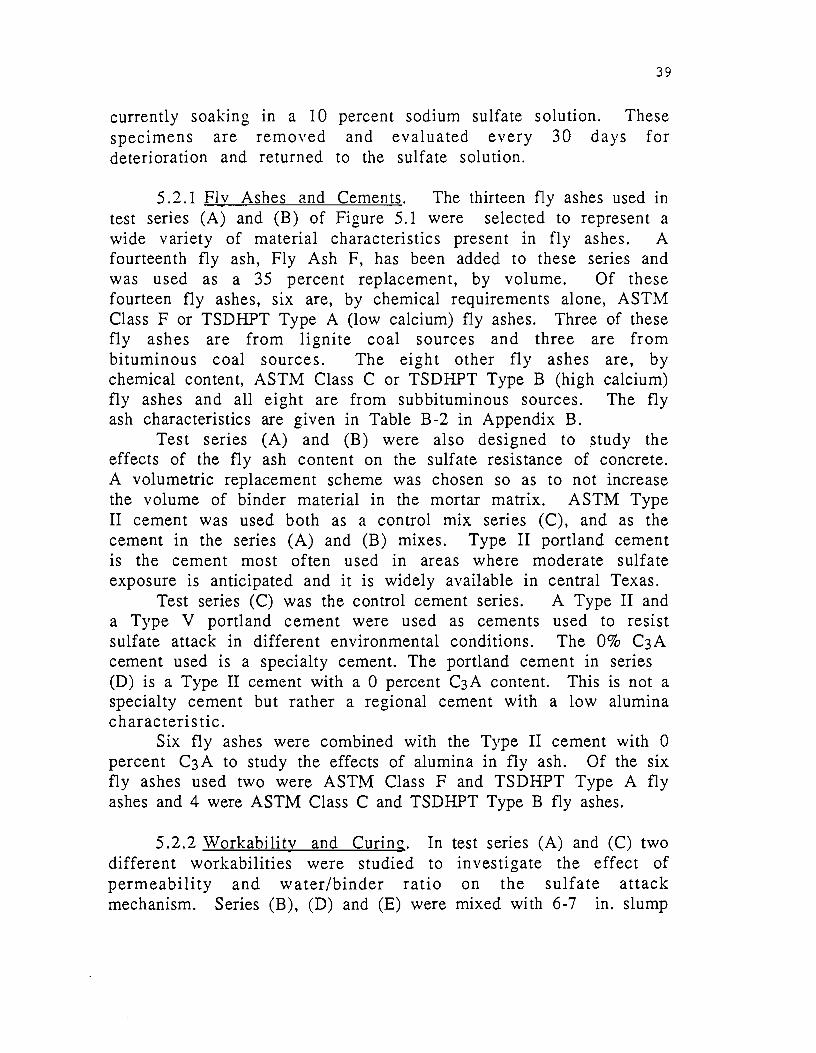
39
currently soaking in a 10 percent sodium sulfate solution. These specimens are removed and evaluated every 30 days for deterioration and returned to the sulfate solution.
5 .2.1 Fly Ashes and Cements. The thirteen fly ashes used in test series (A) and (B) of Figure 5.1 were selected to represent a wide variety of material characteristics present in fly ashes. A fourteenth fly ash, Fly Ash F, has been added to these series and was used as a 35 percent replacement, by volume. Of these fourteen fly ashes, six are, by chemical requirements alone, ASTM Class F or TSDHPT Type A (low calcium) fly ashes. Three of these fly ashes are from lignite coal sources and three are from bituminous coal sources. The eight other fly ashes are, by chemical content, ASTM Class C or TSDHPT Type B (high calcium) fly ashes and all eight are from subbituminous sources. The fly ash characteristics are given in Table B-2 in Appendix B.
Test series (A) and (B) were also designed to study the effects of the fly ash content on the sulfate resistance of concrete. A volumetric replacement scheme was chosen so as to not increase the volume of binder material in the mortar matrix. ASTM Type II cement was used both as a control mix series (C), and as the cement in the series (A) and (B) mixes. Type II portland cement is the cement most often used in areas where moderate sulfate exposure is anticipated and it is widely available in central Texas.
Test series (C) was the control cement series. A Type II and a Type V portland cement were used as cements used to resist sulfate attack in different environmental conditions. The 0% C3A cement used is a specialty cement. The portland cement in series (D) is a Type II cement with a 0 percent C3A content. This is not a specialty cement but rather a regional cement with a low alumina characteristic.
Six fly ashes were combined with the Type II cement with 0 percent C3A to study the effects of alumina in fly ash. Of the six fly ashes used two were ASTM Class F and TSDHPT Type A fly ashes and 4 were ASTM Class C and TSDHPT Type B fly ashes.
5.2.2 Workability and Curing. In different workabilities were studied to permeability and water/binder ratio mechanism. Series (B), (D) and (E) were
test series (A) and (C) two investigate the effect of on the sulfate attack
mixed with 6-7 in. slump
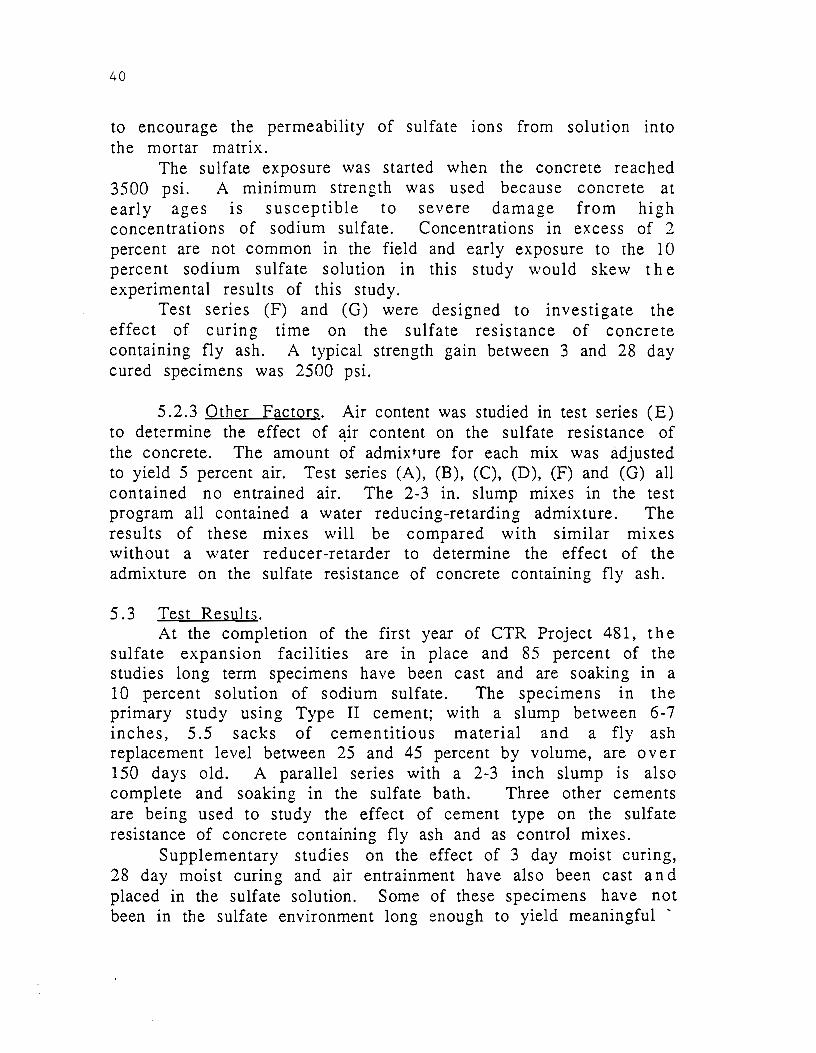
40
to encourage the permeability of sulfate ions from solution into the mortar matrix.
The sulfate exposure was started when the concrete reached 3500 psi. A minimum strength was used because concrete at early ages is susceptible to severe damage from high concentrations of sodium sulfate. Concentrations in excess of 2 percent are not common in the field and early exposure to the 10 percent sodium sulfate solution in this study would skew the experimental results of this study.
Test series (F) and (G) were designed to investigate the effect of curing time on the sulfate resistance of concrete containing fly ash. A typical strength gain between 3 and 28 day cured specimens was 2500 psi.
5 .2.3 Other Factors. Air content was studied in test series (E) to determine the effect of 3;ir content on the sulfate resistance of the concrete. The amount of admixture for each mix was adjusted to yield 5 percent air. Test series (A), (B), (C), (D), (F) and (G) all contained no entrained air. The 2-3 in. slump mixes in the test program all contained a water reducing-retarding admixture. The results of these mixes will be compared with similar mixes without a water reducer-retarder to determine the effect of the admixture on the sulfate resistance of concrete containing fly ash.
5.3 Test Results. At the completion of the first year of CTR Project 481, the
sulfate expansion facilities are in place and 85 percent of the studies long term specimens have been cast and are soaking in a 10 percent solution of sodium sulfate. The specimens in the primary study using Type II cement; with a slump between 6-7 inches, 5.5 sacks of cementitious material and a fly ash replacement level between 25 and 45 percent by volume, are over 150 days old. A parallel series with a 2-3 inch slump is also complete and soaking in the sulfate bath. Three other cements are being used to study the effect of cement type on the sulfate resistance of concrete containing fly ash and as control mixes.
Supplementary studies on the effect of 3 day moist curing, 28 day moist curing and air entrainment have also been cast and placed in the sulfate solution. Some of these specimens have not been in the sulfate environment long enough to yield meaningful '
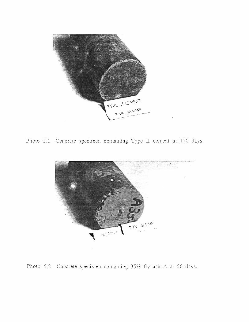
Photo 5.1 Concrete specimen containing Type II cement at 170 days.
Photo 5.2 Concrete specimen containing 35% fly ash A at 56 days.

Photo 5.3 Concrete spec1men containing 45% fly ash B Gt 137 days.
Photo 5 .4 Concre te spec1men containing 45 S"c fl y ash C at 137 days.
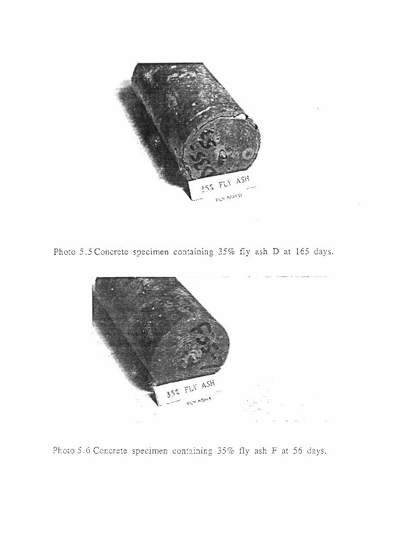
Photo 5.5 Concrete speetmen containing 35 % fly ash D at 165 days.
Ph oto 5 . 6 Concre te specimen cont aining 35 % fly ash F at 56 days .

Photo 5. 7 Concrete specimen containing 35% fly ash H at 169 days.
Ph oto 5. 8 Concrete speCimen containing 35 % fly ash !\1 at 151 days.
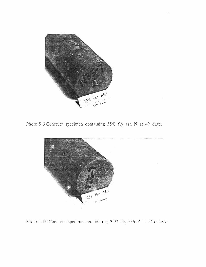
Photo 5. 9 Concrete specimen containing 35% fly ash N at 42 days.
Photo 5. 10 Concrete specimen containing 35% fl y ash P at 165 days.
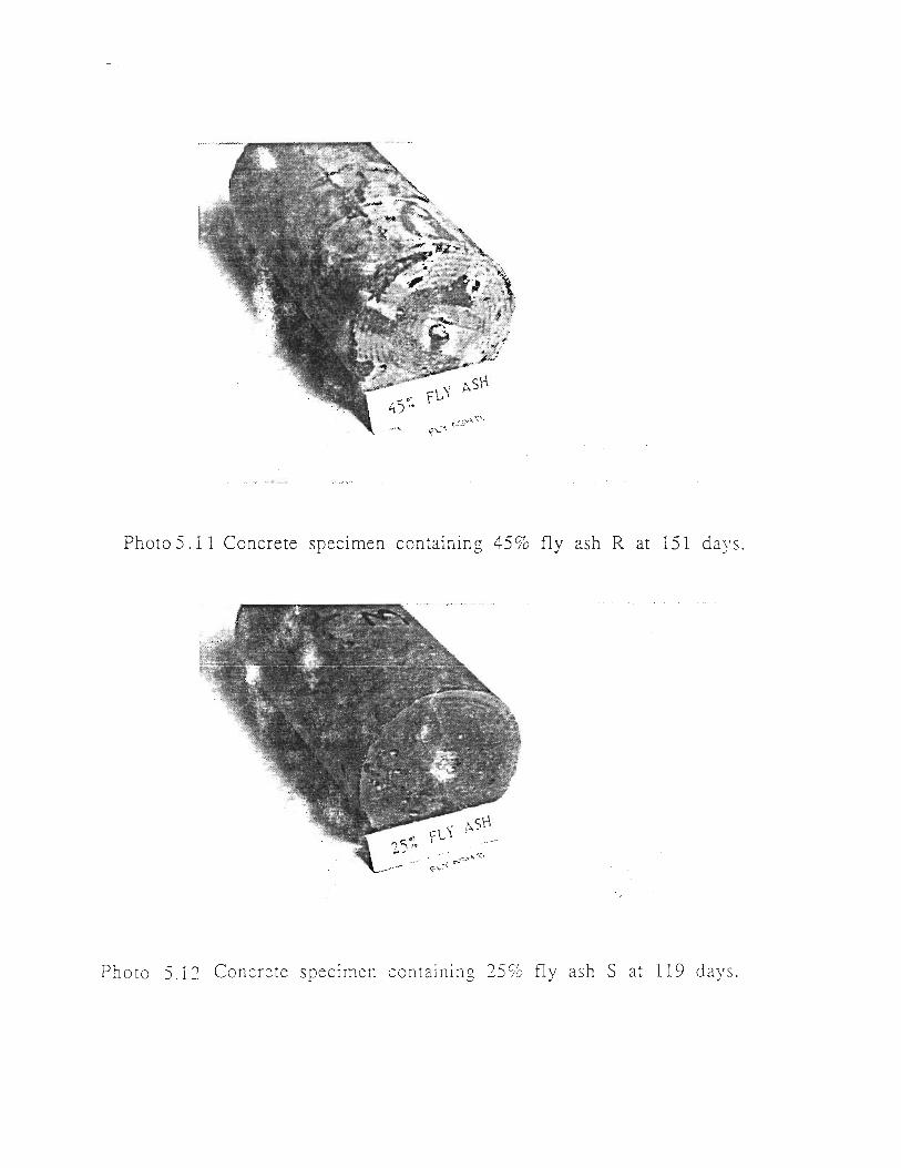
.... - ~ ...
Photo 5.11 Concrete spee1men containin g 45 % fly ash R at 151 d ays.
Photo 5.1:2 Concre te specimen containing 25 % fly ash S at 119 days .
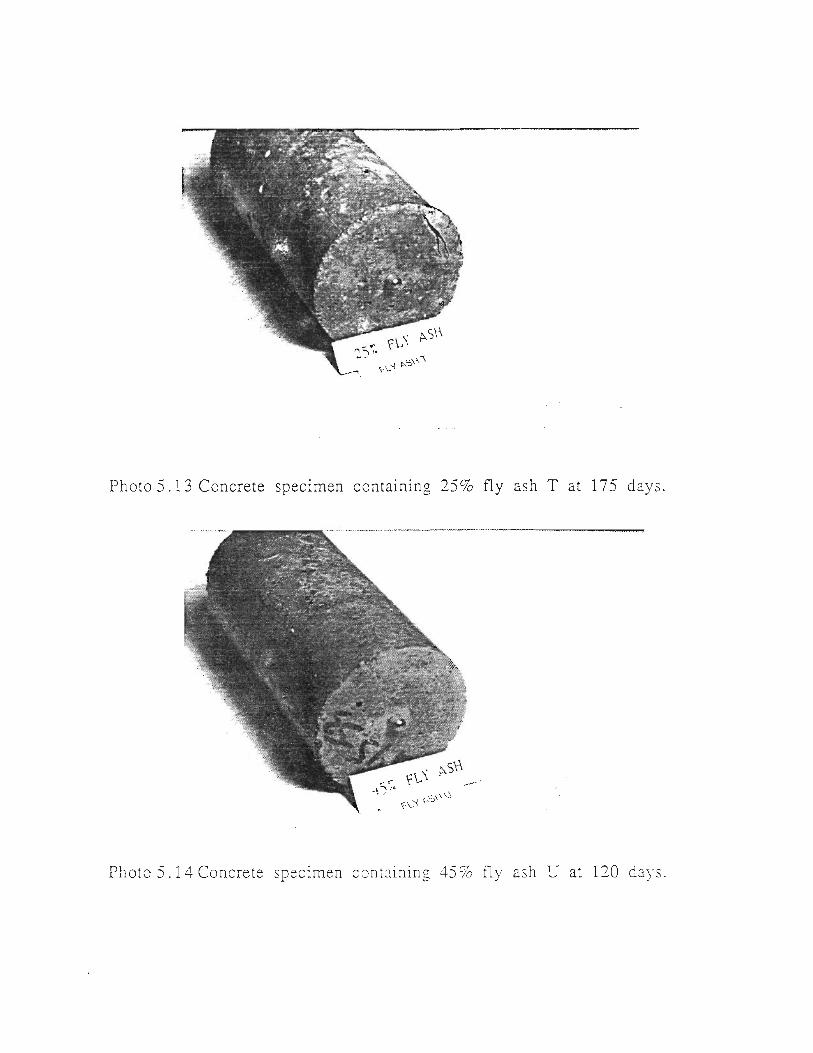
Photo 5.13 Concrete speCimen containing 25% fly ash T at 175 days.
Photo 5.14 Concrete specrmen cont:::ining 45% fl y ash U at 120 days.
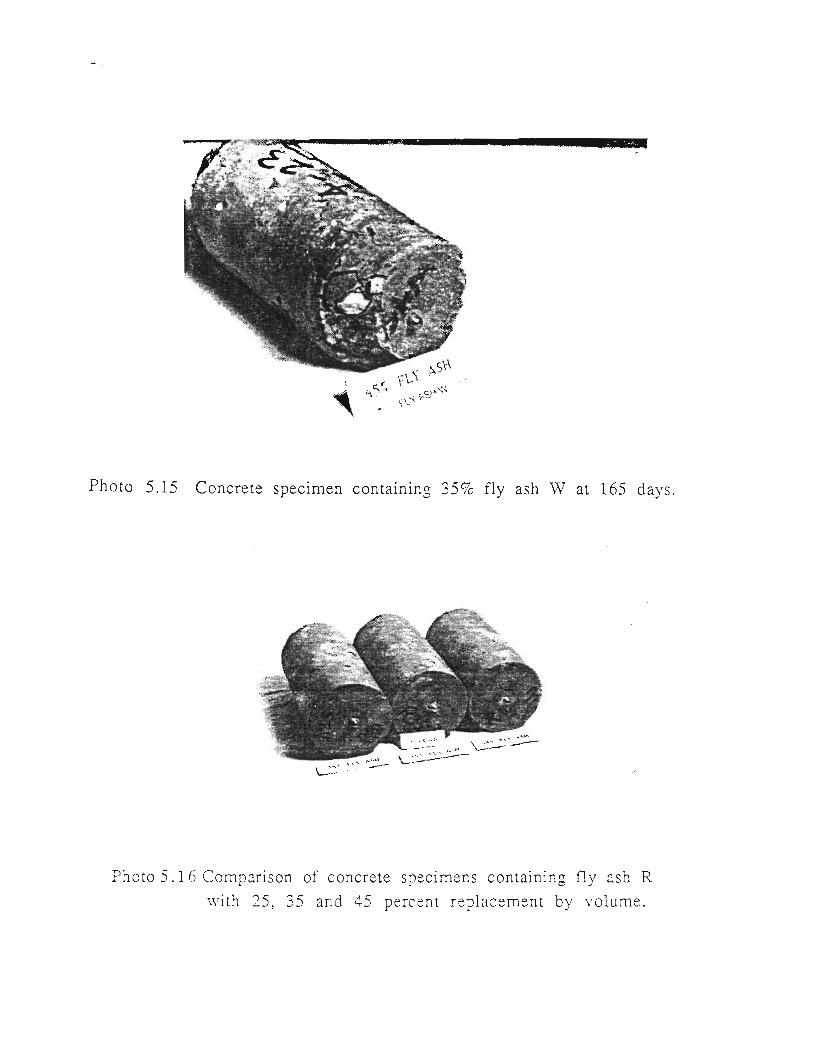
Photo 5.15 Concrete spec1men containing 35% fly ash \V at 165 days.
Photo 5. 1 6 Comparison of concrete specimens containing fly ash R
with 25, 35 and 45 perc ent replacement by volume.

Photo 5.1 7 Comparison of concrete specimens containing fly ash D
with 25, 35 and 45 percent replacement by volume.
Photo 5.1 8 Four phases of sulfate attack on concrete.
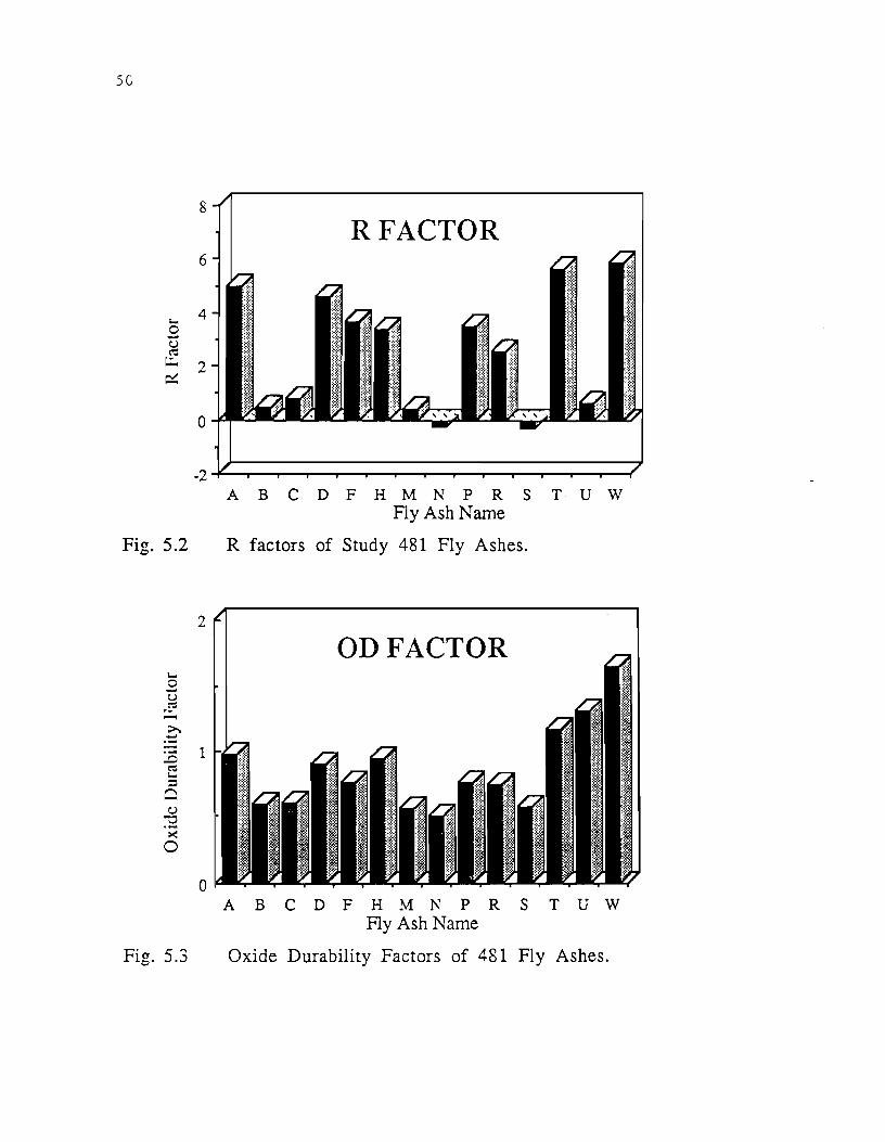
SG
8
6
1-o 4
0 ~
u c-= ~
~ 2
0
-2
Fig. 5.2
2
0
Fig. 5.3
RFACTOR
A B c D F H M N p R s T u w Fly Ash Name
R factors of Study 481 Fly Ashes.
ODFACTOR
A B C D F H M N P R S T U W Fly Ash Name
Oxide Durability Factors of 481 Fly Ashes.

60
50 (I)
~ 40 u .5 - 30 § 0
20 .§ ;a
10 c:a Q. >(
t.:.l 0
-10
Expansion of Concrete Containing Fly Ash A Slump: 6-7 in.: Type II Cement; 5.5 sks/cu.yd.
35% Fly Ash
' 0 .60 Time, days 1 2 0 180
Fly Ash A
Sub bituminous Coal
R factor: 5.00 TSDHPT Type B Fly Ash
Chemical Composition Mineralogical Composition
CaO% 29.86 CaSO 4% X
Si02 % 32.23 C3A% X
A1203% 22.18 Hem% X
Fe fJ 3D 4.97 CaO% X
so3 % 2.48 Mag%
MgO% 5.63 Mel% X
LOI% 0.03 Mul%
MgO% X
Si02
% X
Sp% X
Fig. 5.4 The effect of fly ash A on sulfate resistance.
51

52
til :d u .5
§ 0
0 ·o; r:: ~ Q. ><
t.:.J
Expansion of Concrete Containing Fly Ash B Slump: 6-7 in.; Type II Cement; 5.5 sks/cu.yd.
60
50
40 Fly Ash Content
30 0%
20 25%
10
0
-10 0 50 Time, days 1 o o
Fly Ash B
Texas Lignite Coal
R factor: 0.51 TSDHPT Type A Fly Ash
150
Chemical Composition Mineralogical Composition
CaO% 9.55 CaS04%
SiD.z% 52.90 ~A%
A120fo 17.89 Hem o/o X
Fe 2~% 8.98 CaO%
so3 % 0.90 Mag% X
MgO% 1.66 Mel%
LOI% 0.19 Mul% X
MgO% X
Si02
% X
Sp %
Fig. 5.5 The effect of fly ash B on sulfate resistance.
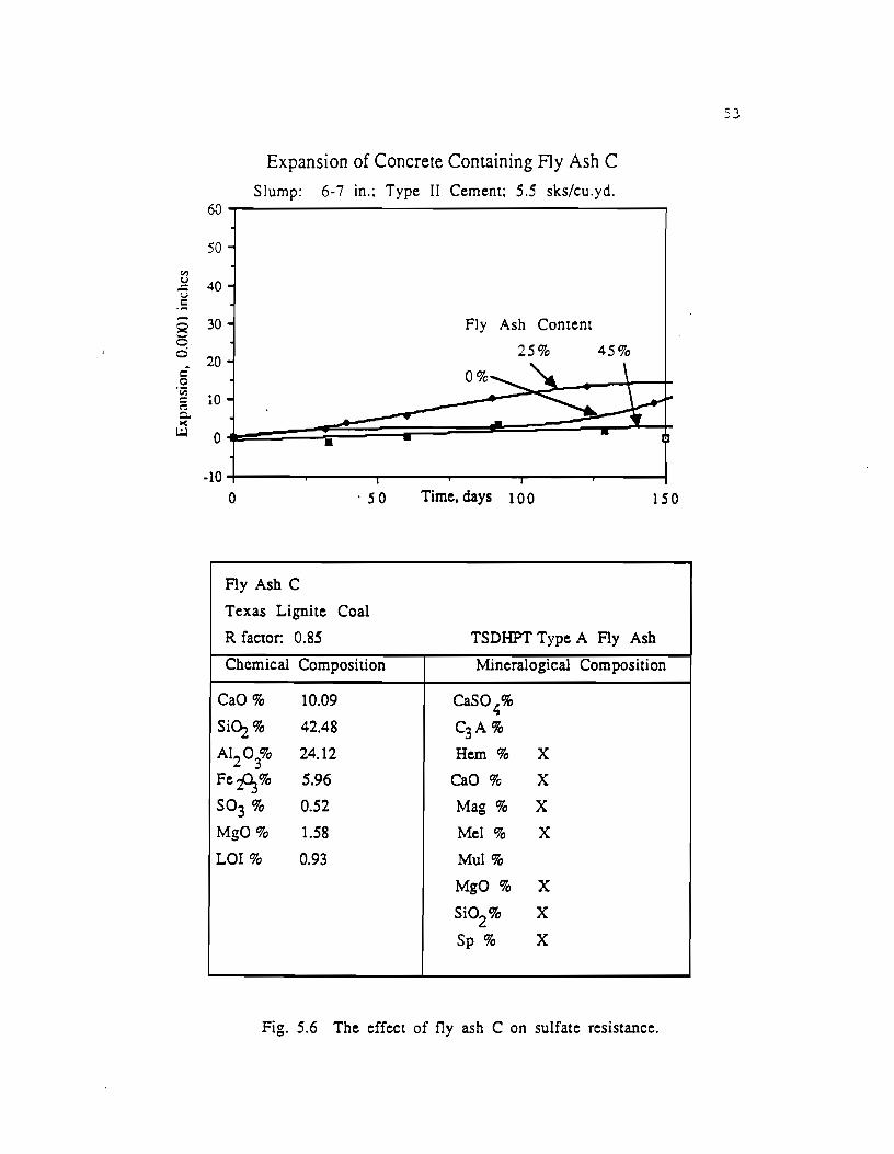
"' ;:: u c
§ 0 c 0 ~~
~ ><
!..:.l
Expansion of Concrete Containing Fly Ash C Slump: 6-7 in.; Type II Cement; 5.5 sks/cu.yd.
60
50
40
30 Fly Ash Content
20 25% 45%
10
0 • -10
0 . 50 Time, days 1 o o 150
Fly Ash C
Texas Lignite Coal
R factor: 0.85 TSDHPT Type A Fly Ash
Chemical Composition Mineralogical Composition
CaO% 10.09 CaS04%
SiC\.2% 42.48 C3A%
AI203% 24.12 Hem% X
FeiJ.3% 5.96 CaO% X
so3 % 0.52 Mag% X
MgO% 1.58 Mel% X
LOI% 0.93 Mul%
MgO% X
Si02
% X
Sp % X
Fig. 5.6 The effect of fly ash C on sulfate resistance.
53
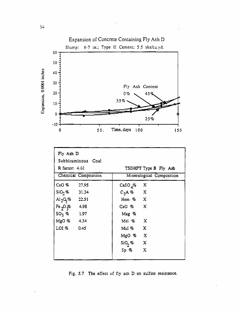
Fly Ash D
Sub bituminous Coal
R factor: 4.61 TSDHPT Type B Fly Ash
Chemical Composition Mineralogical Composition
CaO% 21.95 CaS0 4% X
SiO:z% 31.34 c3A% X
AI 2~% 22.51 Hem% X
Fe 2o;o 4.98 CaO% X
so3 % 1.97 Mag%
MgO% 4.34 Mel % X
LOI% 0.45 Mul% X
MgO % X
Si02
% X
Sp % X
Fig. 5. 7 The effect of fly ash D on sulfate resistance.
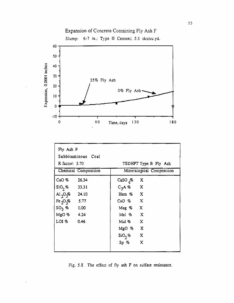
til
~ u .5
§ ci . r: 0 ·v; r: ~ c. ><
L.:J
60
50
40
30
20
10
0
·10
Expansion of Concrete Containing Fly Ash F
Slump: 6· 7 in.; Type II Cement; 5.5 sks/cu.yd.
35% Fly Ash
0 60 Time, days 1 2 o
Fly Ash F
Subbituminous Coal
180
R factor: 3. 70 TSDHPT Type B Fly Ash
Chemical Composition Mineralogical Composition
CaO% 26.34 CaSO 4% X
Si02 % 33.31 C3A% X
A1203% 24.10 Hem% X
Fe£?3% 5.77 CaO% X
so3 % 0.00 Mag% X
MgO% 4.24 Mel% X
LOI% 0.46 Mul% X
MgO % X
Si02
% X
Sp % X
Fig. 5.8 The effect of fly ash F on sulfate resistance.
55
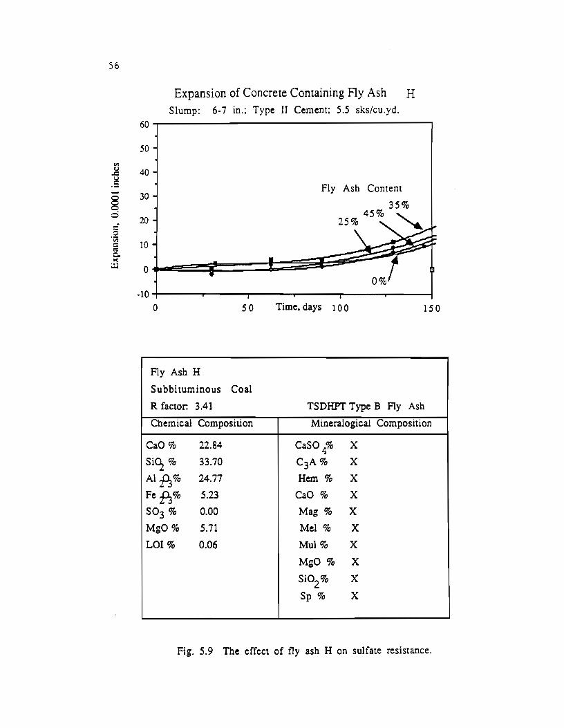
56
Expansion of Concrete Containing Fly Ash H Slump: 6-7 in.; Type IT Cement; 5.5 sks/cu.yd.
60
50
Vl C..l 40 ~
.5 - 30 § 0
20 -3 ·~ 10 a c. I<
r.:J 0
-10
0 50 Time, days 100 15 0
Fly Ash H
Subbituminous Coal
R factor: 3.41 TSDHPT Type B Fly Ash
Chemical Composition Mineralogical Composition
CaO% 22.84 CaSO 4% X
Si<l.z% 33.70 C3A% X
A1fl3% 24.77 Hem% X
Fefl_;% 5.23 CaO% X
so3 % 0.00 Mag% X
MgO% 5.71 Mel% X
LOI% 0.06 Mul% X
MgO % X
Si02
% X
Sp % X
Fig. 5.9 The effect of fly ash H on sulfate resistance.
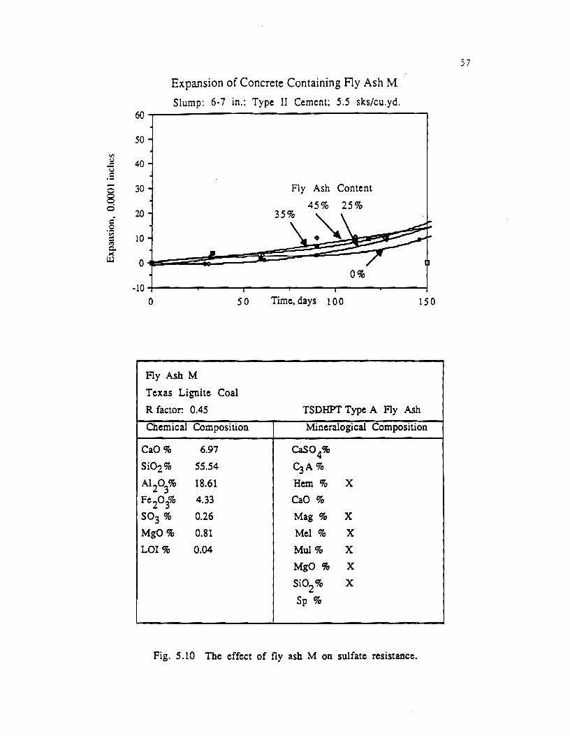
Expansion of Concrete Containing Fly Ash M
Slump: 6-7 in.; Type II Cement; 5.5 sks/cu.yd.
Fly Ash M
Texas Lignite Coal
R factor. 0.45 TSDHPT Type A Fly Ash
Chemical Composition Mineralogical Composition
CaO% 6.97 CaS04%
Si02% 55.54 ~Ao/o
AI 203% 18.61 Hem% X
Fe2o3% 4.33 CaO%
so3 o/o 0.26 Mag% X
MgO% 0.81 Mel% X
LOI% 0.04 Mul% X
MgO% X
Si02 % X
Sp %
Fig. 5.10 The effect of fly ash M on sulfate resistance.
57

58
en ~ u ·= § 0 c 0 ·v; ~ c. :.(
1.::.:1
60
Expansion of Concrete Containing Fly Ash N Slump: 6-7 in.; Type II Cement; 5.5 sks/cu.yd.
50
40
30 35% Fly Ash
20
10 I 0% Fly Ash
~ 0
-10 0 '60 Time, days 1 2 0 180
Fly Ash N
B~tuminous Coal
R factor: -0.21 TSDHPT Type A Fly Ash
ChemiC<l! Composition Mineralogical Composition
CaO% 1.57 CaS0 4%
Si02% 43.04 C3A%
Al 2~% 27.44 Hem% X
Fe2o;o 16.06 CaO% X
so3 % 1.24 Mag% X
MgO% 0.00 Mel%
LOI% 0.90 Mul% X
MgO% X
Si02 % X
Sp % X
Fig. 5.11 The effect of fly ash N on sulfate resistance.
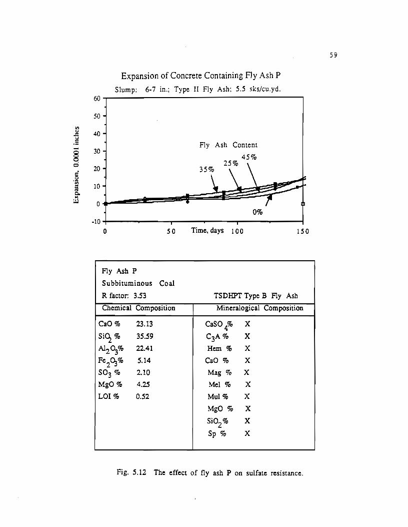
<II t.)
.c u .5 -§ 0 c 0 'iii i Q. II(
~
Expansion of Concrete Containing FJy Ash P Slump: 6-7 in.; Type II Fly Ash: 5.5 sks/cu.yd.
60
50
40
30
20
10
0
-10 0 50
Fly Ash p
Subbituminous Coal
R factor: 3.53
Chemical Composition
CaO% 23.13
siq% 35.59
Al203% 22.41
Fe2C.,% 5.14
so3 % 2.10
MgO% 4.25
LOI% 0.52
Fly Ash Content
45% 25%
0%
Time, days 1 o o 15 0
TSDHPT Type B Fly Ash
Mineralogical Composition
CaSO {/o X
C3A% X
Hem% X
CaO% X
Mag% X
Mel% X
Mul% X
MgO % X
Si02
% X
Sp % X
Fig. 5.12 The effect of fly ash P on sulfate resistance.
59
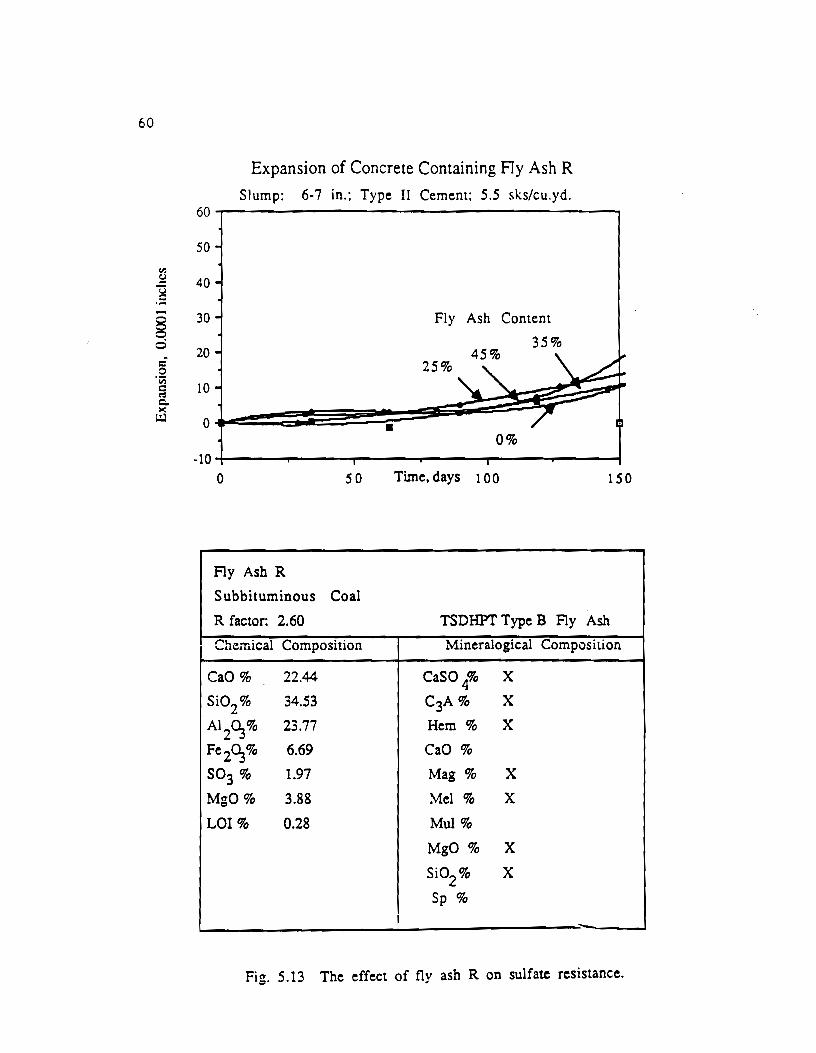
60
Ill
~
.S -§ 0 c 0
'Vi = 1':1 c.. l(
t.:J
Expansion of Concrete Containing Fly Ash R
Slump: 6· 7 in.: Type II Cement; 5.5 sks/cu.yd. 60
50
40
30
20
10
0
·10 0 so
Fly Ash R
Sub bituminous Coal
R factor: 2.60
Chemical Composition
CaO% 22.44
Si02
% 34.53
AI 2G_,% 23.77
Fe 2G_,% 6.69
so3 % 1.97
MgO% 3.88
LOI% 0.28
•
Fly Ash Content
35%
25%
0%
Time, days 1 o o lSO
TSDHPT Type B Fly Ash
Mineralogical Composition
CaSO 4'fo X
C3A% X
Hem% X
CaO%
Mag% X
Mel% X
Mul%
MgO% X
Si02 % X
Sp%
Fig. 5.13 The effect of fly ash R on sulfate resistance.
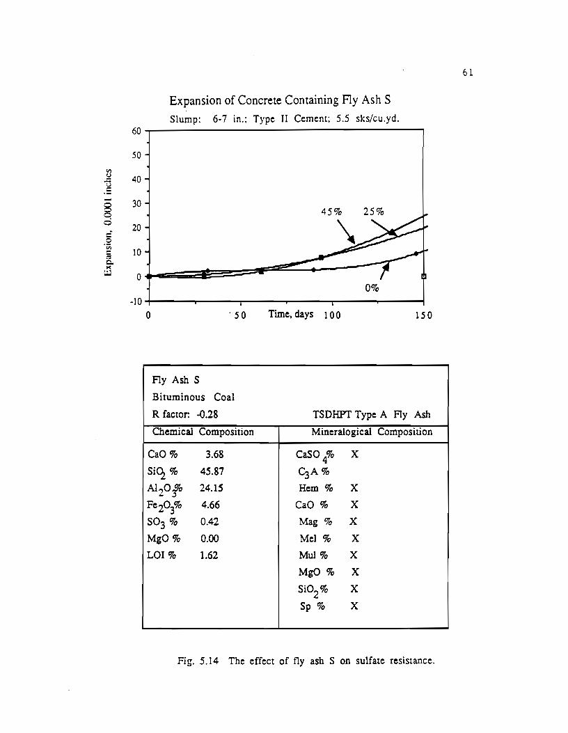
Expansion of Concrete Containing F1y Ash S Slump: 6-7 in.: Type II Cement; 5.5 sks/cu.yd.
60~--------------------------------------,
50
40
30
0% -10 -r----.,..-------,-----........ ---....,...----........ --------1
0 ·so Time, days 1 0 0 15 0
Fly Ash S
Bituminous Coal
R factor: -0.28 TSDHPT Type A Fly Ash
Chemical Composition Mineralogical Composition
CaO% 3.68 CaSO 4% X
Si<1% 45.87 C3A%
A1 20fo 24.15 Hem% X
Fe2o3% 4.66 CaO% X
so3 % 0.42 Mag% X
MgO% 0.00 Mel% X
LOI% 1.62 Mul% X
MgO % X
Si02
% X
Sp % X
Fig. 5.14 The effect of fly ash S on sulfate resistance.
61

62
60
50 <ll !::!
40 ]
§ 30 0 c 20 c ·cr. c 10 1':: c. ><
t.:J 0
-10
Expansion of Concrete Containing Fly Ash T
Slump: 6· 7 in.: Type II Cement: 5.5 sks/cu.yd.
45%
25%
• 0 50 Time, days 1 0 0
Fly Ash T
Subbituminous Coal
R factor: 5.65 TSDHPT Type B Fly
150
Ash
Ch~mical Composition Mineralogical Con1posilion
CaO% 31.34 CaSO 4% X
SiO.z% 30.80 C3A% X
Al2C:;% 21.94 Hem% X
Fe2o3% 4.66 CaO% X
so3 % 2.28 Mag% X
MgO% - 6,14 Mel% X
LOI% 0.17 Mul%
MgO% X
Si02
% X
Sp% X
Fig. 5.15 The effect of fly ash T on sulfate resistance.
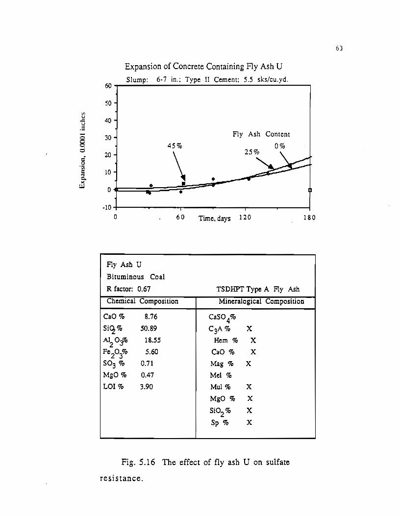
"' ~ ]
§ 0 . 8 ~u;
::: co: 0. >(
UJ
60
Expansion of Concrete Containing Fly Ash U
Slump: 6-7 in.; Type II Cement; 5.5 sks/cu.yd.
50
40
30
20
10
0
-10
0
Fly Ash U
Bituminous Coal
R factor: 0.67
45%
\ • •
60
•
Fly Ash Content
0%
Time, days 1 2 0
TSDHPT Type A Fly Ash
180
Chemical Composition Mineralogical Composition
CaO% 8.76 CaS04%
SiC2% 50.89 C3A% X
A12 Offo 18.55 Hem% X
Fe2
03% 5.60 CaO% X
so3 % 0.71 Mag% X
MgO% 0.47 Mel%
LOI% 3.90 Mul% X
MgO% X
Si02% X
Sp % X
Fig. 5.16 The effect of fly ash U on sulfate
resistance.
63
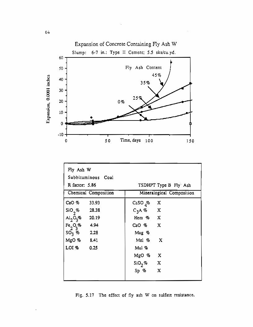
64
60
50
tt.l S:l 40 "!:)
~= - 30 8 0 0
20 c 0
"Iii 10 iij
Q. >(
:.:.l 0
·10
Expansion of Concrete Containing Fly Ash \V
Slump: 6-7 in.: Type II Cement; 5.5 sks/cu.yd.
Fly Ash Content
0%
•
0 50 Time, days 1 0 0 150
Fly Ash w Subbituminous Coal
R factor: 5.86 TSDHPT Type B Fly Ash
Chemical Composition Mineralogical Composition
CaO% 33.93 CaSO 4% X
Si02
% 28.38 C3A% X
AI203% 20.19 Hem% X
Fe2
03% 4.94 CaO% X
so3 % 2.28 Mag%
MgO% 8.41 Mel% X
LOI% 0.25 Mul%
MgO % X
Si02
% X
Sp % X
Fig. 5.17 The effect of fly ash W on sulfate resistance.

65
Expansion of Concrete Containing Fly Ash Slump: 6-7 in.; Type II Cement; 45% Replacement (Vol.)
40
til 30 ::: u .5
§ 20
0 Type II
= 10 0 ·;;;; c • co: c. x 0 ~
Fly Ash C -10
0 s.o Time, days 1 0 0 150
Fig. 5.18 Expansion of three different fly ashes.
Expansion of Concrete Containing Fly Ash Slump: 6-7 in.; Type II Cement; 25% Replacement (Vol.)
40
tl) 30 ::: u .5
Fly Ash W
0 20 8 0 - 10 0 ·;;;; c C': c. x 0 ~
Fly Ash H -10
0 50 Time, days 1 0 0 150
Table 5.19 Expansion of three different fly ashes.
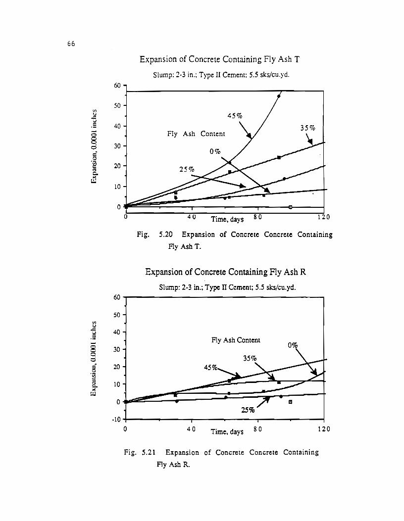
66
60
50 til
~ u 1: 40 -§
30 0 c 0 ·~ 20
<":1 c. ><
I.:.l 10
0
60
50 Vl ~
~ 40
-x 30 0 ci
5 20 ·~ ::: 10 c. l<
I.:.l
0
-10
0
0
Expansion of Concrete Containing Fly Ash T
Slump: 2·3 in.; Type II Cement; 5.5 sks/cu.yd.
Fly Ash Content
40 Time, days 80 120
Fig. 5.20 Expansion of Concrete Concrete Containing
Ay Ash T.
Expansion of Concrete Containing Fly Ash R
Slwnp: 2-3 in.; Type II Cement; 5.5 sks/cu.yd.
Ay Ash Content 0%
40 Time, days 80 120
Fig. 5.21 Expansion of Concrete Concrete Containing
Ay Ash R.
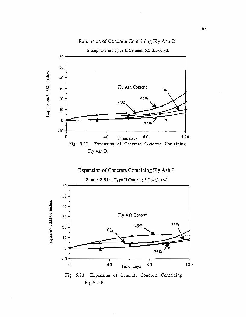
c.l)
S::!
Expansion of Concrete Containing Fly Ash D
Slump: 2-3 in.; Type II Cement; 5.5 sks/cu.yd. 60~--------------------------------------~
50
u 40 .5 -8 0
c.l)
S::!
] -~ -: 0 c 0
'f);
a c. II(
t.:J
30 Fly Ash Content 0%
-10~----~------~----~~----~------~----~
0 4 0 Time, days 8 0 1 2 0 Fig. 5.22 Expansion of Concrete Concrete Containing
60
so
40
30
20
10
0
-10 0
Fig.
Ay Ash D.
Expansion of Concrete Containing Fly Ash P
Slump: 2-3 in.; Type IT Cement; 5.5 sks/cu.yd.
Ay Ash Content
45% 35%
40 Time, days 80
5.23 Expansion of Concrete Concrete Containing
Fly Ash P.
120
67
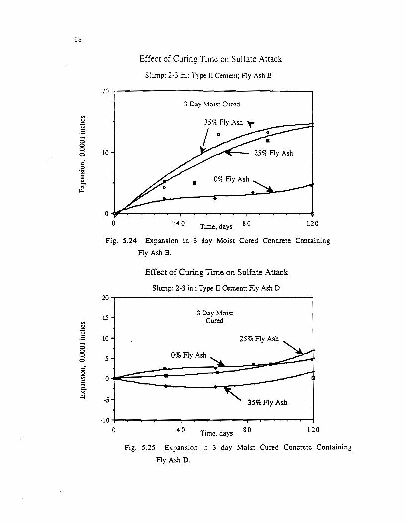
6&
til !:::! u = -0
8 c) . § -~ ?. c:. lo(
L;.l
til !:::!
'"Q
-0 0 0 c)
-0 -~
8.. lo(
L::J
Effect of Curing Time on Sulfate Attack
Slwnp: 2-3 in.; Type II Cement: f1y Ash B
20~--------------------------------------~ 3 Day Moist Cured
10 25% Fly Ash
• 0% Fly Ash
0 0 Time, days 80 1.20
Fig. 5.24 Expansion in 3 day Moist Cured Concrete Containing
Fly Ash B.
Effect of Curing Time on Sulfate Attack
Slump: 2-3 in.; Type IT Cement; Fly Ash D
~~------------------------------------~
15
10
s
0
-5
-10 0
3 Day Moist Cured
0% Fly Ash
40 Time, days
25% Fly Ash
3S% Fly Ash
80 120
Fig. 5.25 Expansion in 3 day Moist Cured Concrete Containing
Fly Ash D.
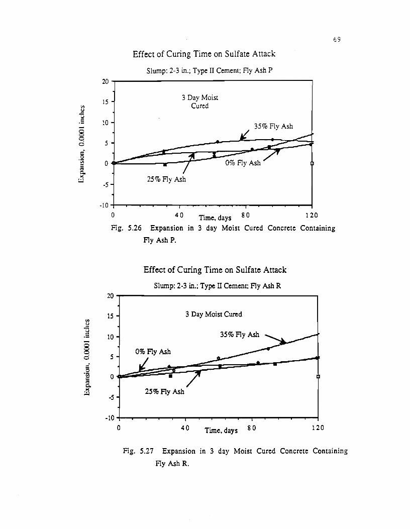
V'l
~ u c::
0 0 0 ci c:: 0 ·~ E Q. ><
t.:.l
<:~)
~
] -8 C! 0
§ ·c;; c:: <':! Q,. ><
t.:.l
20
15
10
5
0
-5
-10
0
Effect of Curing Time on Sulfate Attack
Slump: 2-3 in.; Type II Cement: Fly Ash P
3 Day Moist Cured
35% Fly Ash
4 0 Time, days 8 0 1 2 0
69
Fig. 5.26 Expansion in 3 day Moist Cured Concrete Containing
Fly Ash P.
20
15
10
5
0
-5
-10 0
Effect of Curing Time on Sulfate Attack
Slump: 2-3 in.; Type II Cement; Fly Ash R
3 Day Moist Cured
35%Fly Ash
2S%Fly Ash
40 Time, days 80 120
Fig. 5.27 Expansion in 3 day Moist Cured Concrete Containing
Fly Ash R.

70
Expansion of Control Concrete
Slump: 6-7 in.; 5.5 sks/cu.yd.; 3500 psi 20
15 "' !:!
"'(j .5 10 0
0% C3A Cement Type II Cement
8 5 0
§ ·sa 0 rs c. I<
t.:.l -5 Type V Cement
-10 0 40 Time, Days 8 0 120
Fig. 5.28 Expansion of Control Concrete Mixes.
20 Expansion of 0% C3A Cement Concrete
Slump: 6· 7 in.; 5.5 sks/cu.yd.; 35% Fly Ash
15 "'
Fly Ash W !:! ] 10
• Fly AshP
s 5 0 -0 -~ 0 a. I< ~
Fly Ash B -5
-10
0 30 Time, Days 6 0 90
Fig. 5.29 Expansion of Concrete Containing Blue Circle Cement.

20
15 Cll
!:I 'TI .5 10 -0
8 0 5 c: 0
"iii 0 ~ c... ><
t.:J -5
-10
20
15 ~ ]
10 -§ 0 5
§ ·~ a
0 Q., ><
t.:J -5
-10
0
Fig.
0
Effect of Curing Time on Sulfate Attack
Slump: 2-3 in.: Type II Cement: Fly Ash D
3 Day Moist Cured
• • 28 Day Moist Cured
4 0 Time, days 8 0 1 2 0
5.30 Effect of Different Curing Times on Expansion.
Effect of Curing Time on Sulfate Attack
Slump: 2-3 in.; Type IT Cement; Fly Ash R
28 Day Moist Cured
3 Day Moist Cured
40 Time, days 80 120
Fig. 5.31 Effect of Different Curing Times on Expansion.
71
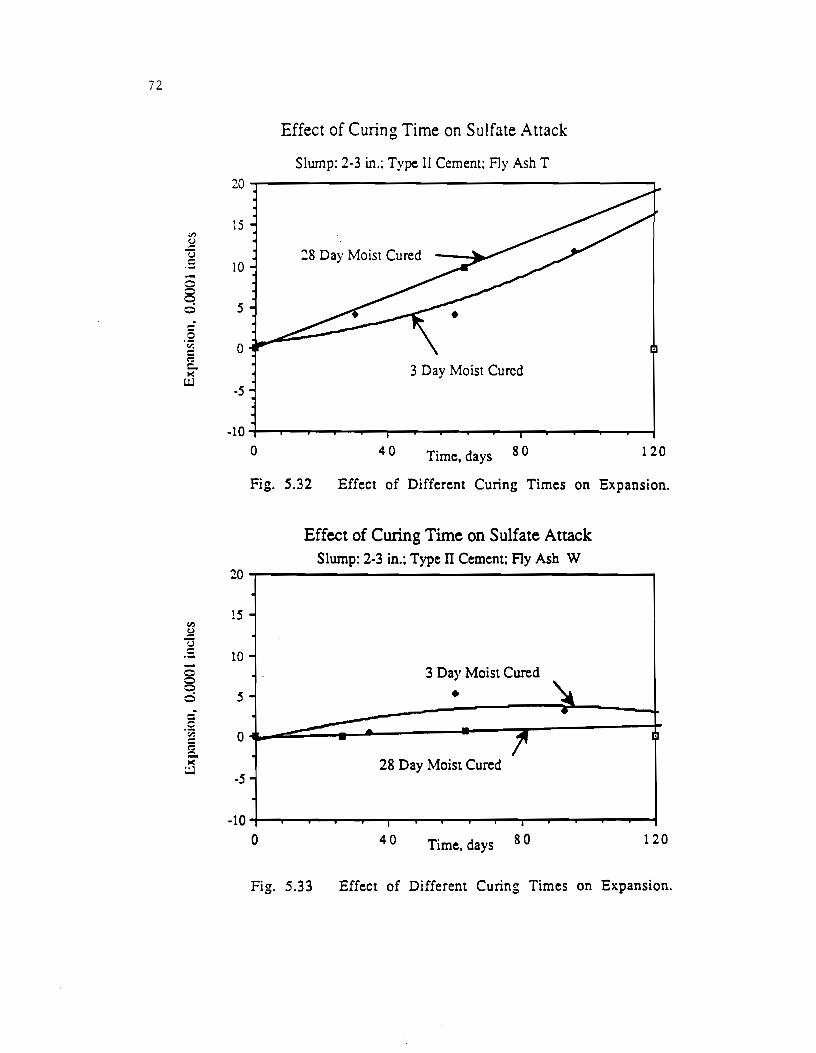
72
-§
Effect of Curing Time on Sulfate Attack
Slwnp: 2-3 in.: Type II Cement: Fly Ash T
20~----------------------------------------~
15
10 :!8 Day Moist Cured
ci 5
II)
~ u
0
3 Day Moist Cured -5
-10~~--~~--~~~~~~--.--r--~~~--~~
0 40 Time, days 80 120
Fig. 5.32 Effect of Different Curing Times on Expansion.
Effect of Curing Time on Sulfate Attack Slump: 2-3 in.; Type II Cement; Fly Ash W
20~----------------------------------------~
15 -
.s 10--§ ci 5
3 Day Moist Cured
• 0~~~~=;~-------.-~,~------~
28 Day Moist Cured -5
-10~~--~~--~~.~~~--~~--r-1~--~~~~
0 40 Time, days 80 120
Fig. 5.33 Effect of Different Curing Times on Expansion.

13
results. However, radial cracking is present m some of these specimens and expansions are being monitored.
Photos 5.1 through 5.15 show the physical condition of specimens containing each type of fly ash after soaking in the sodium sulfate solution. Photos 5.16 and 5.17 display the effect of fly ash content on the degradation of concrete. Photo 5.18 shows the four phases of degradation from sulfate attack through a cross sectional view of the specimens. The specimen on the bottom right is undamaged, while the one on the bottom left shows· small radial cracks around the outside rim of the specimen. The top left specimen displays spalling and large radial cracking. The specimen shown in the top right has failed and falls apart at the touch.
Figures 5.2 and 5.3 show the the R factors and OD factors, respectively, of the fly ashes used in this study. The MinChem R factor will be investigated more thoroughly in the next stage of the study.
The expansion behavior of the 6· 7 inch slump series is reported in Figures 5.4 through 5.17. These figures also summarize the chemical and crystalline phase characteristics of the fly ash. Figures 5.18 and 5.19 compare the expansions of three different fly ashes, but the same cement replacement level of fly ash. The expansion of concrete with 2·3 in. s 1 u m p containing fly ashes T, R, D, and P are shown in Figures 5.20 through 5.23, respectively. Figures 5.24 through 5.27 show the effect of curing time on the sulfate expansion of concrete containing fly ash. Figure 5.28 is a plot of the expansions of the control specimens. Figure 5.29 shows the expansions of the concrete proportioned with Type II cement with 0 percent C3A and fly ash. The effect of curing time is shown in Figures 5.30 through 5.33.
The mass change of concrete subjected to the 10 percent sulfate solution is shown in Figures 5.34 and 5.35. In addition to the results presented in this section, the strength and curing information is presented in Table B·5 of Appendix B.
5.4 Discussion of Test Results. The test results from the first year are largely inconclusive.
The expansion tests require more time to develop a decisive trend
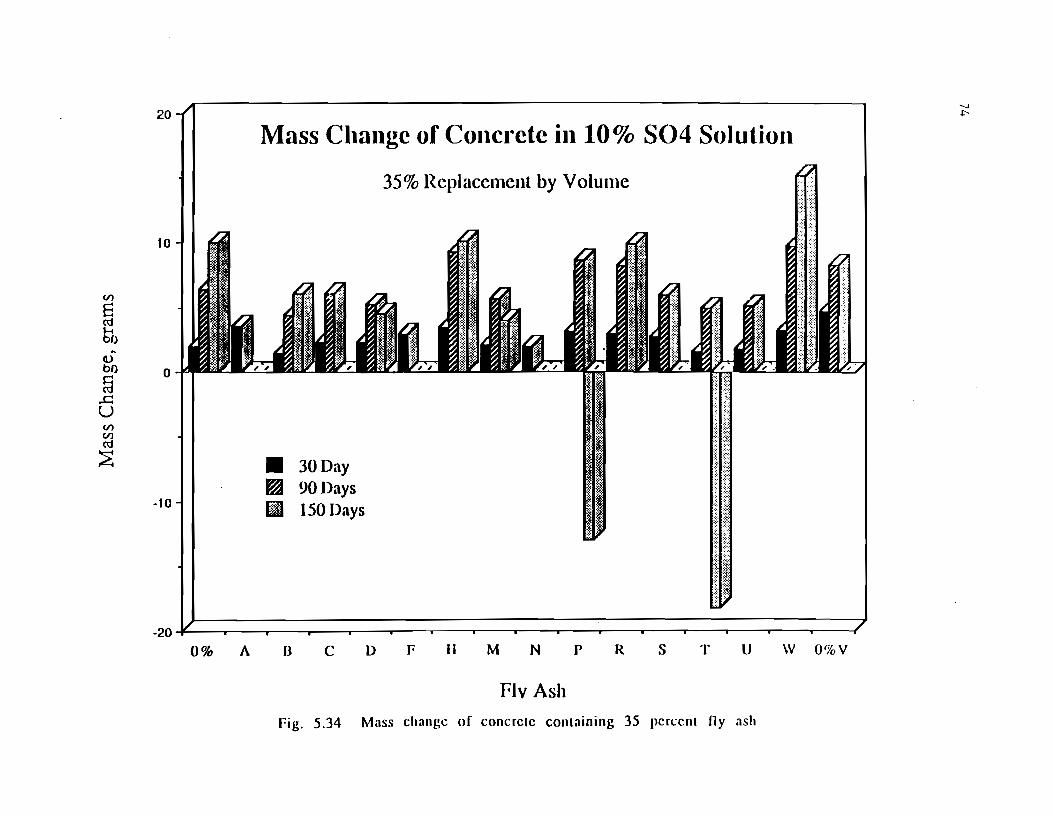
Cl)
El cd 61) .. Cl) bl)
§ ..c:: u Cl) Cl)
cd
~
20
Mass Change of Concrete in 10% S04 Solution
35% Rcplaccmcnl by Volmnc
10
0
;t::: ,_.,,,,
I I • 30Day FA~ 90Days
-10 -t I JiJ 150 Days
-20~--~--~--~~--r---~--~--~---r---,----r---~--~---r--~--~~--~
0% A B C D F II M N p R s T U W 0%V
Flv Ash Fig. 5.34 Mass change of concrete containing 35 percent ny ash
"-.J -I"
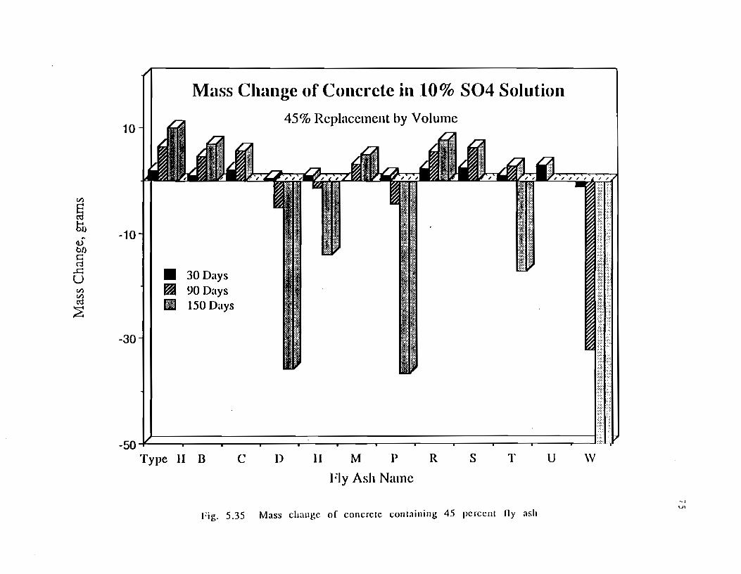
V)
~ So ~
d)
bO s:: c"j
...c:: u V) V) ro ~
10
-10
j -30
Mass Change of Concrete in 10% S04 Solution
45% Replacement by Volume
• 30Days ~ 90Days 111 150 Days
-50~~~~~~~~~~~~===;==~==~~==~==~==~~ Type II B .,,~.~ c 11 R s \V u T M jl D
FJy Ash Name
fig. 5.35 Mass change of concrete containing 45 percent lly ash
,, Ul
76
m the data. However some concrete has deterioration and excessive expansions during exposure testing. In addition, several comparisons factors are possible based on test results to date.
shown physical the 180 days of to the OD and R
The low calcium fly ashes from lignite and bituminous coal sources, B, C, M, N, S, and U, have performed well in the sulfate environment. Specimens cast with these fly ashes, regardless of the percent replacement or workability, show no signs of cracking, loss of mass or expansive damage. These fly ashes had the lowest R and OD factors and are characterized by low calcium contents, and low free lime contents, with the exception of fly ash U. Fly ash U had a free lime content over 2.0 percent according to the ASTM C114 Sr(N03)2 Method and the second highest OD factor. This is the highest free lime content of all of the fly ashes in this study. The crystalline phases of these six fly ashes were characterized by little or no anhydrite, melilite or tricalcium aluminate and the presence of mullite, quartz and magnetite. The significance of these compounds will be more thoroughly investigated in the second year of the study.
The results of the concrete containing high calcium fly ashes from subbituminous coal sources in less clear. The eight high calcium fly ashes used in this study showed a range of physical deterioration from no damage to complete failure. Failure was judged by both exceeding 0.1 percent expansion and by the inability to measure the specimen for mass loss or expansions due to deterioration. Typically, the specimens cracked radially in the first stage of deterioration and failed by a horizontal through crack in the middle section of the cylinder. The specimens made with fly ash W showed very poor resistance to sulfate attack, with those specimens containing a higher percentage of fly ash deteriorating at a higher rate than those with less fly ash, as shown in Figure 5.17. Fly ash T also performed poorly when proportioned with a 2-3 in. slump, as shown in Figure 5 .20. Why the 6-7 in. slump concrete proportioned with fly ash T did not deteriorate at the same or faster rate is being studied more closely. Fly ash W and T were characterized as having a highest calcium oxide contents of the fly ashes in this study and the highest free lime contents of the fly ashes from subbituminous coal sources. The crystalline phases of these two fly ashes indicate a strong presence of tricalcium aluminate, hematite and periclase

77
and a diminished presence of magnetite. Fly ash A shows these same characteristics, but the specimens are too young to draw any conclusions. In addition to the composition characterization already stated, fly ash \V contains a strong presence of anhydrite, melilites, mullite and quartz; whereas fly ash T and A had less intense peaks of anhydrite, melilites and quartz and a diminished presence of mullite. The R and OD factors would both indicate poor performance of these fly ashes m sulfate environments.
Three of the remaining five high calcium fly ashes, D, H, and P, have shown signs of physical degradation when used at higher volume replacement levels. Radial cracking and minor spalling is evident in these specimens, but expansions have not approached failure. This is evident from the changes in mass shown in Figures 5.34 and 5.35. These three high calcium fly ashes are characterized as having calcium oxide and free lime contents in the mid-range of the subbituminous based fly ashes, i.e. 23 to 28 percent and 0.10 to 0.60, respectively. The crystalline phase identification of these fly ashes reveal the presence of tricalcium aluminate, melilites, anhydrite, hematite, periclase, mullite and quartz; except in fly ash H which had strong peaks of quartz and anhydrite. Both the R and OD factors would predict marginal to poor performance of these fly ashes in sulfate environment. It is too soon to evaluate the results of concrete cast with fly ash F, but this fly ash has much the same chemical and crystalline characterization as fly ashes D, H, and P with the exception that shows a diminished presence of quartz and free lime. The R and OD factors would predict a marginal performance for fly ash F in sulfate environments.
Fly ash R has shown good performance in the first part of this study. There are small radial cracks in the specimens containing 45 percent fly ash, but no mass loss or physical deterioration is noted on any of the other specimens containing fly ash R. The R and OD factors would predict marginal performance. The calcium oxide and the free lime contents of both fly ashes are at the lower end of the range for subbituminous coal fly ashes. The crystalline phase analysis shows a diminished presence of hematite, mullite and quartz and the presence of tricalcium aluminate, anhydrite, magnetite, melilites and periclase.

The meamng of the first years results are still unclear because of the long term nature of the sulfate attack mechanism. A more thorough discussion will be possible when the next stage of this experimental program is complete. However, there is enough conclusive evidence based on the observed deterioration of the specimens to implement restrictions stated in the next section.
CHAPTER 6
SUMMARY
6.1 Summarv of First Year Results. Work during the first year of this study concentrated on
setting up and starting the implementation of the sulfate expansion experiment. Over 200 of the 600 long term specimens have been soaking in the 10 percent solution of Na2S 04 solution for over 150 days. Of these specimens only one set of specimens have reached the 0.1 percent expansion limit. Four specimens have been rendered unmeasurable because of the physical damage, however many specimens are showing physical distress.
At 150 days, the control Type II portland cement along with a Type V and two 0 percent C3A cements have shown no excessive expansions or cracking from the sulfate environment. The TSDHPT Type A fly ashes which include fly ashes from bituminous and lignite sources have performed very well, even when used at replacement levels as high as 45 percent by volume of Type II portland cement. The TSDHPT Type B fly ashes have shown varied amounts of expansion. The tendency is to have more physical damage when A Type B fly ash is used at higher replacement levels.
The Type B fly ashes with a strong presence of crystalline C 3A have been the most severely damaged by expansions. An analysis of the validity of the R and OD factors show that they generally indicate the trends of expansive concrete containing fly ash, however they are oversimplified by not considering the supersulfating mechanism, or inert crystalline compounds in fly ash. The MinChem R factor, in its present form, has not accurately predicted the expansive damage in concrete containing fly ash. However, this factor is still being developed and may be more applicable with modifications.
The second year will be dedicated to performing quantitative analysis on the concrete containing fly ash in the sulfate environment. Ion permeability of the concrete, XRD on the hydration products, petrographic analysis are among the tests to be performed. In addition, several more fly ashes will be brought
79
80
into the study and further development of a prediction method will be pursued.
The advisory panel for this study has provided valuable technical and material assistance. In the second year we hope to draw on information from other studies to better understand the problem of sulfate attack on concrete containing fly ash.
6.2 Implementation. This report summarizes the findings of the first year· of a
three year study on the effects of fly ash on the sulfate resistance of concrete containing fly ash. The preliminary findings show that there is a relationship between fly ash composition and sulfate resistance.
This interim report is an overview of the complete experimental project on the sulfate resistance of concrete containing fly ash. The first year's results indicate that the use of high calcium fly ash increase the potential for sulfate attack of concrete. Some lignitic fly ashes add to the sulfate resistance of concrete. On the basis of results to date, recommendations have been made to TSDHPT officials and these recommendations have been incorporated into job concrete specifications to allow only TSDHPT Type A fly ash for the use of concrete exposed to sulfate environments. Until further research produces a means of ensuring adequate sulfate resistance of concrete containing TSDHPT type B fly ash, their use should be restricted to concrete not subjected to sulfate attack.

1) Harboe, Edward M., "Longtime Studies and Field Experience with Sulfate Attack," Geor~e Verbeck Svmposi u m on S u !fate Resistance of Concrete, American Concrete Institute Special Publication, SP-77 -1, pp 1-20, 1980.
2) Dunstan, Edwin R., Jr., "A Possible Method for Identifying Fly Ashes That Will Improve the Sulfate Resistance of Concretes," Cement, Concrete and Aggregates, CCAGDP, Vol. 2, No. 1, Summer 1980, pp 20-30.
3) Reading, Thomas J., "Physical Aspects of Sodium Sulfate Attack on Concrete," George Verbeck Symposium on Sulfate Resistance of Concrete, American Concrete Institute Special Publication, SP-77-5, pp 75-82, 1980.
4) American Society of Testing and Materials, 1987 Annual Book of ASTM Standards, Section 4, Construction, Vol. 4.02 Concrete and Aggregates, ASTM 1987.
5) Reynolds, Micheline, "Chemical Durability of Concrete," Contemporary European Concrete Research, Stockholm, June 1981.
6) Manz, Oscar E., McCarthy, Greg J., el. al., "Resistance of Lignite and Subbituminous Fly Ash Concrete: Test Results and Proposal for an Improved R-Factor," Presented at the Bryant and Katherine Mather International Conference on Concrete Durability, unpublished, Atlanta, GA, 1987.
7) Mehta, P. K., "Effect of Fly Ash Composition on Sulfate Resistance of Cement,~' American Concrete Institute Journal/ NovDec 1986, pp.994-1000.
8) Hartmann, Carl and Mangotich, Edward, "A Method of Predicting Sulfate Durability of Concrete," Concrete Durabilitv. Brvant and Katherine Mather International Conference, American Concrete Institute Special Publication, SP-100-110, 1987.
81
/32
9) Watt, J.D. and Thorne, D.J., "Composition and Pozzolanic Properties of Pulverized Fuel Ashes, I. Composition of Fly Ashes from Some British Power Stations and Properties of Their Component Particles," Journal of Applied Chemistry, Vol. 15, pp 585-594, 1965.
1 0) Lea, F. M., "The Chemistry of Cement and Concrete," Chemical Publishing Co., New York, 1971.
11) Kalousek, G. L., Benton, E. J., "Mechanisms of Sea Water Attack on Cement Paste," Proceedings of American Concrete Institute, Vol. 76, No. 2, 1970.
12) Helmuth, Richard, F1y Ash in Cement and Concrete, Portland Cement Association, 1987.
13) Dunstan, Edwin R., Jr., "Fly Ash and Fly Ash Concrete," United States Bureau of Reclamation Engineering and Research Center, Repon REC-ERC-82-1, May 1984.
14) Mather, Katherine, "Factors Affecting Sulfate Resistance of Mortars," United States Army Waterways Experimental Station, Structures Laboratory, Miscellaneous Paper SL-80-17, October, 1980.
15) McCarthy, G.J., Swanson, K.D. Keller, L.P., Blatter, W.C., "Mineralogy of Western Fly Ash," Cement and Concrete Research, Vol. 14, pp. 471.;478, 1984.
16)Dunstan, Edwin R., "A Spec Odyssey-Sulfate Resistant Concrete for the 80's," Georae Verbeck Svmposium on Sulfate Resistance of Concrete, American Concrete Institute Special Publication, SP-77-3, pp 41-62, 1980.

APPENDIX A
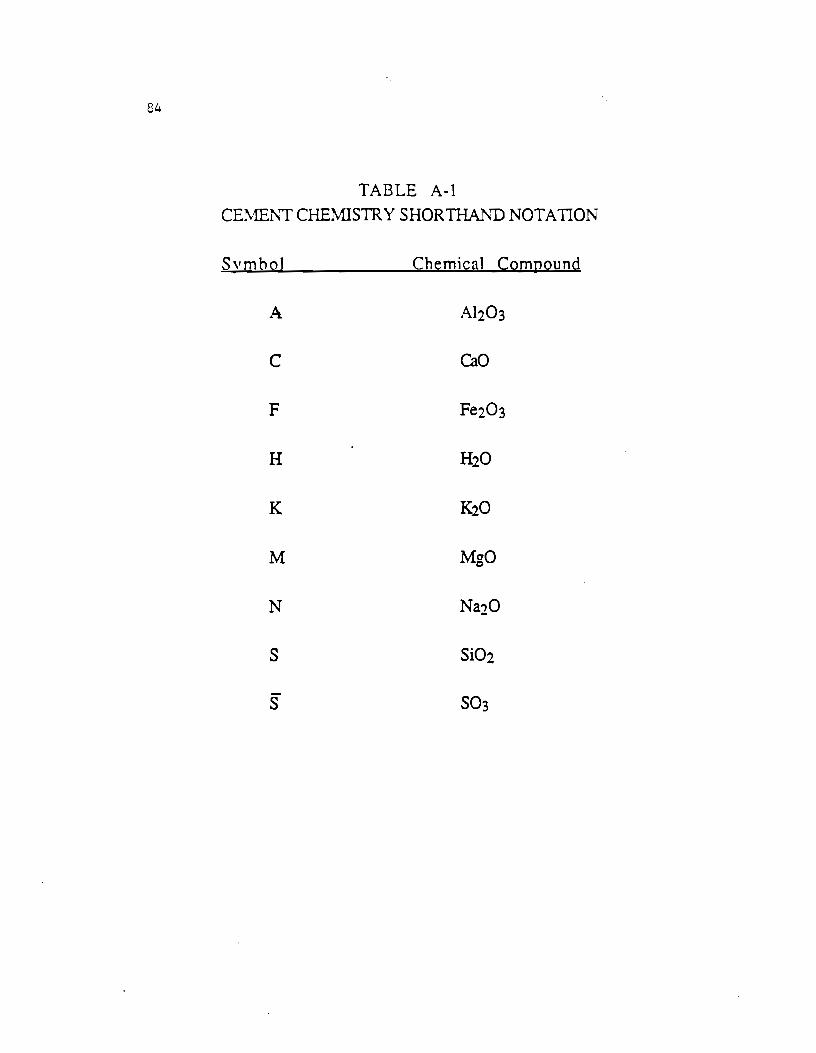
84
TABLE A-1 CEME:L\'T CHEM1STR Y SHORTHAJ'..'D NOTATION
Svmbol Chemical Compound
A Al203
c CaO
F Fe203
H H20
K K20
M MgO
N Na20
s Si02
s S03
. APPENDIX B
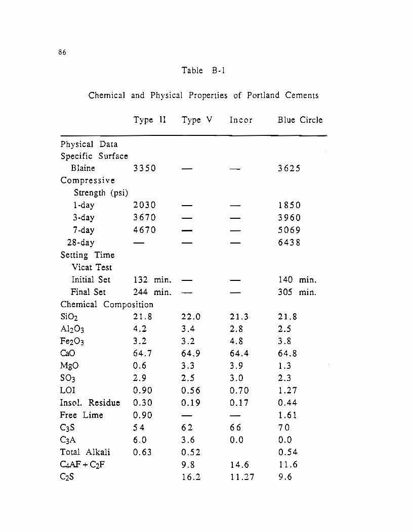
86
Table B·l
Chemical and Physical Properties of Portland Cements
Type II Type V Inc or Blue Circle
Physical Data Specific Surface
Blaine 3350 3625 Compressive
Strength (psi) 1-day 2030 1850 3-day 3670 3960 7-day 4670 5069
28-day 6438 Setting Time
Vicat Test Initial Set 132 min. 140 min. Final Set 244 min. 305 mm.
Chemical Composition Si02 21.8 22.0 21.3 21.8 Ah03 4.2 3.4 2.8 2.5 Fe203 3.2 3.2 4.8 3.8 CaO 64.7 64.9 64.4 64.8 MgO 0.6 3.3 3.9 1.3 so3 2.9 2.5 3.0 2.3 LOI 0.90 0.56 0.70 1.27 In sol. Residue 0.30 0.19 0.17 0.44 Free Lime 0.90 1.61 C3S 54 62 66 70 C3A 6.0 3.6 0.0 0.0 Total Alkali 0.63 0.52 0.54 C4Af+C2F 9.8 14.6 11.6 C2S 16.2 11.27 9.6
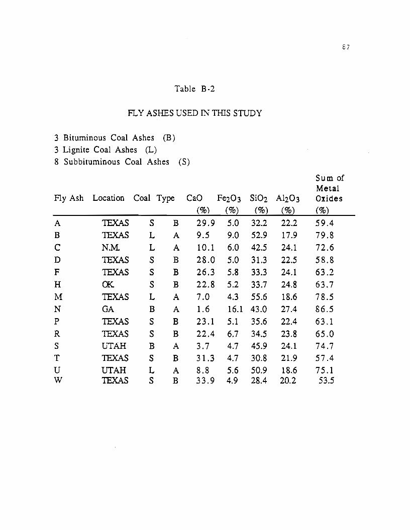
87
Table B-2
FLY ASHES USED IN THIS STUDY
3 Bituminous Coal Ashes (B)
3 Lignite Coal Ashes (L)
8 Subbituminous Coal Ashes (S)
Sum of Metal
Fly Ash Location Coal Type CaO Fe203 Si02 Al203 Oxides (%) (%) (%) (%) (%)
A 1EXAS s B 29.9 5.0 32.2 22.2 59.4
B 1EXAS L A 9.5 9.0 52.9 17.9 79.8
c N.M L A 10.1 6.0 42.5 24.1 72.6
D 1EXAS s B 28.0 5.0 31.3 22.5 58.8
F 1EXAS s B 26.3 5.8 33.3 24.1 63.2
H a<:. s B 22.8 5.2 33.7 24.8 63.7
M TEXAS L A 7.0 4.3 55.6 18.6 78.5
N GA B A 1.6 16.1 43.0 27.4 86.5 p 1EXAS s B 23.1 5.1 35.6 22.4 63.1
R 1EXAS s B 22.4 6.7 34.5 23.8 65.0 s UTAH B A 3.7 4.7 45.9 24.1 74.7 T 1EXAS s B 31.3 4.7 30.8 21.9 57.4
u UTAH L A 8.8 5.6 50.9 18.6 75.1 w TEXAS s B 33.9 4.9 28.4 20.2 53.5
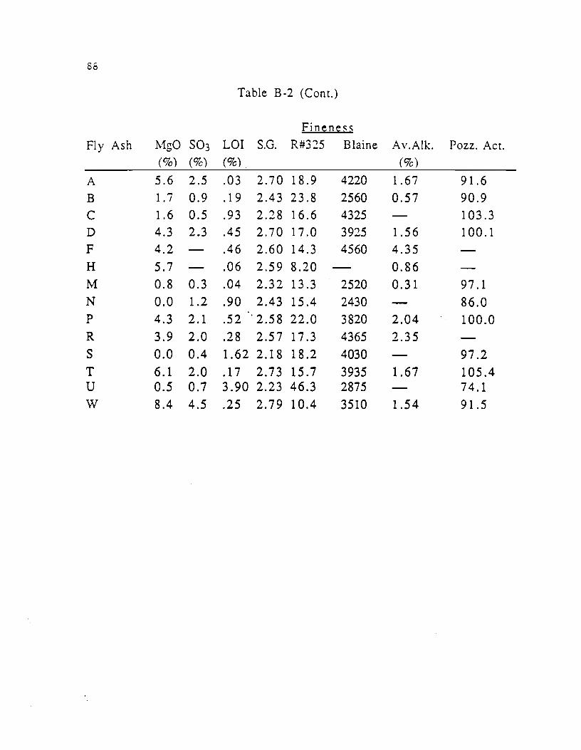
86
Table B -2 (Cont.)
Fineness
Fly Ash 11g0 S03 LOI S.G. R#325 Blaine Av.Alk. Pozz. Act. (%) (%) (%) (%)
A 5.6 2.5 .03 2.70 18.9 4220 1.67 91.6
B 1.7 0.9 .19 2.43 23.8 2560 0.57 90.9 c 1.6 0.5 .93 2.28 16.6 4325 103.3 D 4.3 2.3 .45 2.70 17.0 3925 1.56 100.1 F 4.2 .46 2.60 14.3 4560 4.35 H 5.7 .06 2.59 8.20 0.86 M 0.8 0.3 .04 2.32 13.3 2520 0.31 97.1 N 0.0 1.2 .90 2.43 15.4 2430 86.0 p 4.3 2.1 .52 '2.58 22.0 3820 2.04 100.0 R 3.9 2.0 .28 2.57 17.3 4365 2.35 s 0.0 0.4 1.62 2.18 18.2 4030 97.2 T 6.1 2.0 .17 2.73 15.7 3935 1.67 105.4 u 0.5 0.7 3.90 2.23 46.3 2875 74.1 w 8.4 4.5 .25 2.79 10.4 3510 1.54 91.5
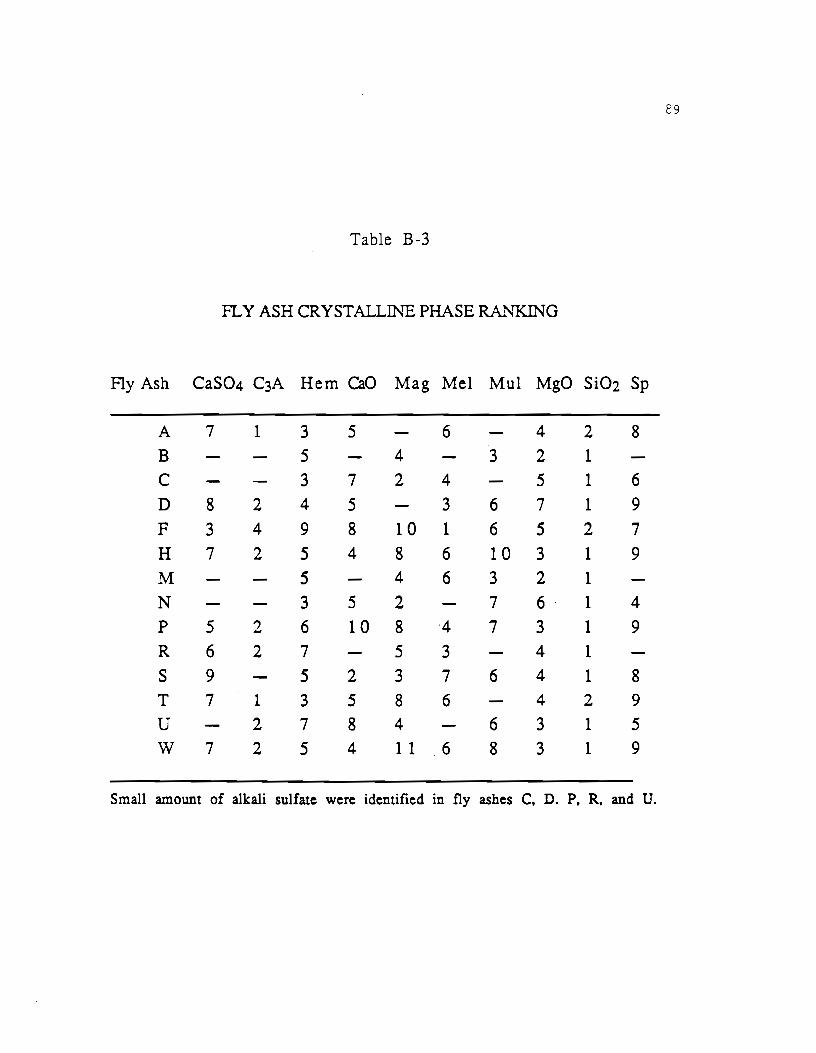
29
Table B-3
F1.. Y ASH CRYSTALLil\TE PHASE RANKING
Fly Ash CaS04 C3A Hem CaO Mag Mel Mul MgO Si02 Sp
A 7 1 3 5 6 4 2 8 B 5 4 3 2 1 c 3 7 2 4 5 1 6 D 8 2 4 5 3 6 7 1 9
F 3 4 9 8 10 1 6 5 2 7 H 7 2 5 4 8 6 10 3 1 9
M 5 4 6 3 2 1 N 3 5 2 7 6 1 4 p 5 ., 6 10 8 ·4 7 3 1 9 -R 6 2 7 5 3 4 1 s 9 5 2 3 7 6 4 1 8 T 7 1 3 5 8 6 4 2 9
u 2 7 8 4 6 3 1 5 w 7 2 5 4 1 1 6 8 3 1 9
Small amount of alkali sulfate were identified in fly ashes C. D. P. R. and U.

s-o
Table B-4
CONCRETE ~1IX PROPORTIONS (per cubic yard at SSD)
~1ix No. Cement Fly Ash Stone Sand Water Admixture
CNTL45 565.4 0.0 1613.7 1499.7 246.8 none CNTL55 580.5 0.0 1657.0 1387.5 267.0 none CNTL 45-2 558.7 0.0 1591.2 1534.9 248.8 none CNTL 55-2 568.2 0.0 1607.9 1357.9 301.9 none CNTL53 516.2 0.0 1565.7 1519.1 274.5 none CNTL47 508.9 0.0 1543.6 1586.0 260.0 none CNTL49 519.8 0.0 1662.9 1662.9 242.8 none CNTL46 505.8 0.0 1590.1 1590.1 263.7 none TYPEV 7 522.1 0.0 1536.6 1536.6 258.8 none TYPEV 3 511.1 0.0 1550.1 1605.7 249.6 none ZER07 507.3 0.0 1530.5 1492.6 301.5 none ZER03 516.2 0.0 1565.7 1621.9 235.5 none T25-7 390.6 114.6 1579.5 1532.5 262.4 none T35-7 335.5 159.0 1585.5 1519.1 274.6 none T45-7 284.9 205.2 1570.9 1524.4 269.8 none W25-7 387.2 116.1 1565.9 1519.8 274.1 none W35-7 337.6 163.6 1575.1 1528.8 266.0 none W45-7 286.7 211.3 1575.3 1534.0 263.4 none H25-7 369.9 111.0 1576.7 1529.9 264.8 none H35-7 341.1 157.0 1591.1 1543.8 252.2 none H45-7 296.1 201.0 1582.3 1535.8 256.0 none ?25-i 3S8.8 107.8 1572.6 1525.9 268.5 none P35-7 337.5 151.3 1574.5 1527.8 266.7 none P45-7 287.3 195.7 1584.7 1537.7 257.8 none B25-7 391.6 102.3 1583.6 1536.7 258.8 none B35-7 347.3 146.5 1619.9 1516.6 248.0 none B45-7 283.9 182.0 1585.6 1519.0 274.6 none M25-7 391.7 97.7 1584.1 1537.2 258.3 none M35-7 342.1 137.9 1595.7 1548.4 248.1 none M45-7 288.5 176.7 1591.0 1543.8 252.3 none 025-7 389.1 113.0 1573.7 1525.9 267.5 none 035-7 338.1 158.6 1577.2 1530.4 264.3 none 045-7 289.1 205.9 1594.2 1545.9 249.5 none R25-7 394.9 109.2 1596.8 1549.4 247.3 none R35-7 335.7 149.9 1558.1 1519.5 277.2 none R45-7 285.0 193.3 1563.9 1525.1 272.3 none S25-7 380.1 89.2 1537.3 1491.6 299.3 none $45-7 289.4 166.5 1595.9 1548.5 248.0 none C25-7 387.1 94.9 1565.6 1519.1 274.6 none C45-7 283.8 170.9 1565.5 1519.0 274.6 none U25-7 389.3 93.25 1574.4 1527.6 256.9 none U45-7 286.0 168.4 1577.5 1530.6 264.1 none
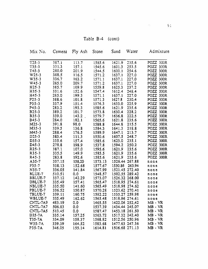
s l
Table B-4 (cont)
Mix .Ko. Cement Fly Ash Stone Sand \Vater Admixture
T25-3 3 87.1 113.7 1585.6 1621.9 235.6 POZZ 300R T35-3 331.3 157.1 1545.6 1601.3 253.5 POZZ 300R T45-3 280.0 201.9 1544.5 1600.1 254.6 POZZ 300R W25-3 388.5 116.5 1571.2 1637.1 227.0 POZZ 300R W35·3 336.7 163.2 1571.1 1637.1 227.0 POZZ 300R W45-3 285.0 209.7 1571.2 1637.1 227.0 POZZ 300R H25-3 385.7 109.9 1559.8 1625.3 237.2 POZZ 300R H35-3 331.6 152.6 1547.4 1612.4 248.4 POZZ 300R H45-3 285.0 199.3 1571.1 1637.1 227.0 POZZ 300R P25-3 388.6 101.8 1571.3 1627.8 230.4 POZZ 300R P35-3 337.9 151.4 1576.3 1633.0 225.9 POZZ 300R P45-3 283.2 193.3 1585.6 1621.9 235.6 POZZ 300R B25·3 389.2 101.7 1573.8 1630.4 228.2 POZZ 300R B35-3 339.0 143.2 . 1579.7 1636.8 222.5 POZZ 300R B45-3 284.0 182.1 1565.6 1621.8 235.6 POZZ 300R M25·3 391.8 98.0 1588.8 1644.8 215.5 POZZ 300R M35-3 339.5 136.8 1584.3 1641.3 218.8 POZZ 300R M45-3 288.4 176.5 1589.9 1647.1 213.7 POZZ 300R D25-3 383.4 111.3 1550.6 1607.5 248.7 POZZ 300R D35-3 335.6 157.4 1585.6 1623.0 235.1 POZZ 300R D45-3 278.8 198.9 1537.8 1594.2 250.2 POZZ 300R R25-3 387.1 107.0 1595.6 1621.9 235.6 POZZ 300R R35-3 335.5 149.9 1585.5 1621.9 235.6 POZZ 300R R45-3 283.8 192.6 1585.6 1621.9 235.6 POZZ 300R A35-7 337.15 158,20 1573.13 1526.44 267.88 none F35-7 338.13 152.68 1577.67 1530.86 263.94 none N35-7 336.05 141.84 1567.99 1521.45 272.40 none BLUE-7 510.51 0.0 1548.57 1502,55 289.42 none BBLUE-7 337.12 142.29 1573.07 1526.32 268.00 none DBLUE-7 335.49 157.41 1565.47 1518.95 274.61 none NBLUE-7 335.50 141.60 1565.49 1518.98 274.62 none PBLUE-7 336.52 150.87 1570.28 1523.62 270.41 none TBLUE-7 339.11 160.75 1582.22 1535.27 259.98 none WBLUE-7 335.49 162.62 1565.48 1518.96 274.61 none Cl\'TL-7A9 483.19 0.0 1465.55 1422.06 252,42 MB- VR Cl\'TL-7A7 506.83 0.0 1537.39 1434.44 245.07 MB- VR CNTL-7A5 513.45 0.0 1587.47 1453.18 261.50 MB- VR D35-7A 335.14 157.25 1563.72 1517.32 242.40 MB- VR T35-7A 334.09 158.37 1568.82 1512.56 250.96 MB- VR W35-7A 339.39 164.52 1583.68 1477.63 247.36 MB- VR P35-7A 346.05 155.14 1614.81 1506.68 271.13 MB -VR
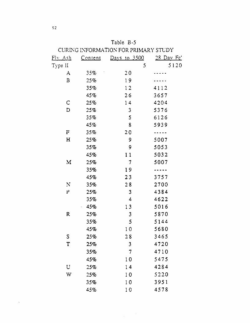
92
Table B-5 ClJRii\G II\ 'FORMATION FOR PRIMARY STUDY
Fl" ;-\ s h Content Days to ~500 2R Dav Fe' Type II 5 5120
A 35% 20 B 25% 1 9
35% 12 4112 45% 26 3657
c 25% 1 4 4204 D 25% 3 5376
35% 5 6126 45% 8 5939
F 35% 20 H 25% 9 5007
35% 9 5053 45% 1 1 5032
M 25% 7 5007 35% 1 9 45% 23 3757
N 35% 28 2700 p 25% 3 4384
35% 4 4622 45% 13 5016
R 25% 3 5870 35% 5 5144 45% 1 0 5680
s 25% 28 3465 T 25% 3 4720
35% 7 4710 45% 1 0 5475
u 25% 14 4284 w 25% 10 5220
35% 10 3951 45% 10 4578