Embed Size (px)
Citation preview
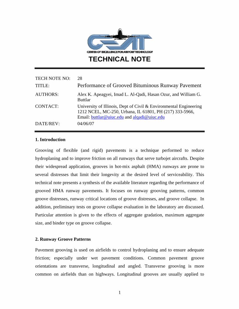
TECHNICAL NOTE
TECH NOTE NO: 28 TITLE: Performance of Grooved Bituminous Runway Pavement AUTHORS: Alex K. Apeagyei, Imad L. Al-Qadi, Hasan Ozur, and William G.
Buttlar CONTACT: University of Illinois, Dept of Civil & Environmental Engineering
1212 NCEL, MC-250, Urbana, IL 61801, PH (217) 333-5966, Email: [email protected] and [email protected]
DATE/REV: 04/06/07
1. Introduction
Grooving of flexible (and rigid) pavements is a technique performed to reduce
hydroplaning and to improve friction on all runways that serve turbojet aircrafts. Despite
their widespread application, grooves in hot-mix asphalt (HMA) runways are prone to
several distresses that limit their longevity at the desired level of serviceability. This
technical note presents a synthesis of the available literature regarding the performance of
grooved HMA runway pavements. It focuses on runway grooving patterns, common
groove distresses, runway critical locations of groove distresses, and groove collapse. In
addition, preliminary tests on groove collapse evaluation in the laboratory are discussed.
Particular attention is given to the effects of aggregate gradation, maximum aggregate
size, and binder type on groove collapse.
2. Runway Groove Patterns
Pavement grooving is used on airfields to control hydroplaning and to ensure adequate
friction; especially under wet pavement conditions. Common pavement groove
orientations are transverse, longitudinal and angled. Transverse grooving is more
common on airfields than on highways. Longitudinal grooves are usually applied to
1
reduce noise and to improve directional control of vehicles. Various groove profiles have
been used including rectangular, trapezoidal and rounded. Guidelines and standards for
construction and maintenance of runway grooves are available through FAA (1). These
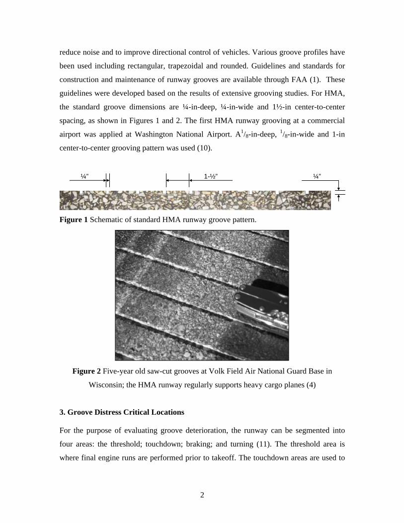
guidelines were developed based on the results of extensive grooving studies. For HMA,
the standard groove dimensions are ¼-in-deep, ¼-in-wide and 1½-in center-to-center
spacing, as shown in Figures 1 and 2. The first HMA runway grooving at a commercial
airport was applied at Washington National Airport. A1/8-in-deep, 1/8-in-wide and 1-in
center-to-center grooving pattern was used (10).
¼” 1-½” ¼”
Figure 1 Schematic of standard HMA runway groove pattern.
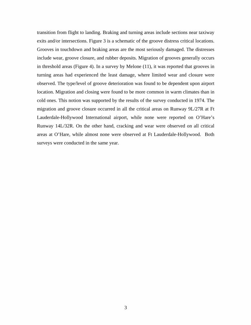
Figure 2 Five-year old saw-cut grooves at Volk Field Air National Guard Base in
Wisconsin; the HMA runway regularly supports heavy cargo planes (4)
3. Groove Distress Critical Locations
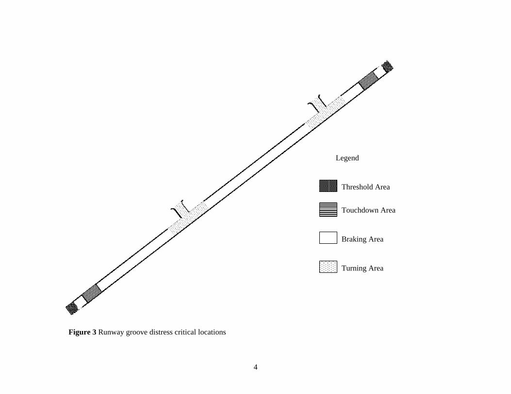
For the purpose of evaluating groove deterioration, the runway can be segmented into
four areas: the threshold; touchdown; braking; and turning (11). The threshold area is
where final engine runs are performed prior to takeoff. The touchdown areas are used to
2
3
transition from flight to landing. Braking and turning areas include sections near taxiway
exits and/or intersections. Figure 3 is a schematic of the groove distress critical locations.
Grooves in touchdown and braking areas are the most seriously damaged. The distresses
include wear, groove closure, and rubber deposits. Migration of grooves generally occurs
in threshold areas (Figure 4). In a survey by Melone (11), it was reported that grooves in
turning areas had experienced the least damage, where limited wear and closure were
observed. The type/level of groove deterioration was found to be dependent upon airport
location. Migration and closing were found to be more common in warm climates than in
cold ones. This notion was supported by the results of the survey conducted in 1974. The
migration and groove closure occurred in all the critical areas on Runway 9L/27R at Ft
Lauderdale-Hollywood International airport, while none were reported on O’Hare’s
Runway 14L/32R. On the other hand, cracking and wear were observed on all critical
areas at O’Hare, while almost none were observed at Ft Lauderdale-Hollywood. Both
surveys were conducted in the same year.
Touchdown Area
Threshold Area
Braking Area
Turning Area
Legend
4
Figure 3 Runway groove distress critical locations
4. Common Groove Distresses
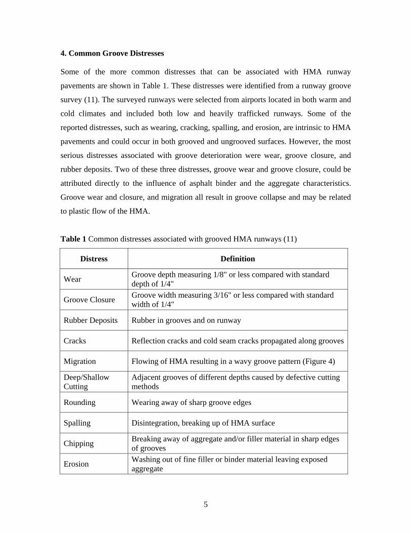
Some of the more common distresses that can be associated with HMA runway
pavements are shown in Table 1. These distresses were identified from a runway groove
survey (11). The surveyed runways were selected from airports located in both warm and
cold climates and included both low and heavily trafficked runways. Some of the
reported distresses, such as wearing, cracking, spalling, and erosion, are intrinsic to HMA
pavements and could occur in both grooved and ungrooved surfaces. However, the most
serious distresses associated with groove deterioration were wear, groove closure, and
rubber deposits. Two of these three distresses, groove wear and groove closure, could be
attributed directly to the influence of asphalt binder and the aggregate characteristics.
Groove wear and closure, and migration all result in groove collapse and may be related
to plastic flow of the HMA.
Table 1 Common distresses associated with grooved HMA runways (11)
Distress Definition
Wear Groove depth measuring 1/8" or less compared with standard depth of 1/4"
Groove Closure Groove width measuring 3/16" or less compared with standard width of 1/4"
Rubber Deposits Rubber in grooves and on runway
Cracks Reflection cracks and cold seam cracks propagated along grooves
Migration Flowing of HMA resulting in a wavy groove pattern (Figure 4)
Deep/Shallow Cutting
Adjacent grooves of different depths caused by defective cutting methods
Rounding Wearing away of sharp groove edges
Spalling Disintegration, breaking up of HMA surface
Chipping Breaking away of aggregate and/or filler material in sharp edges of grooves
Erosion Washing out of fine filler or binder material leaving exposed aggregate
5
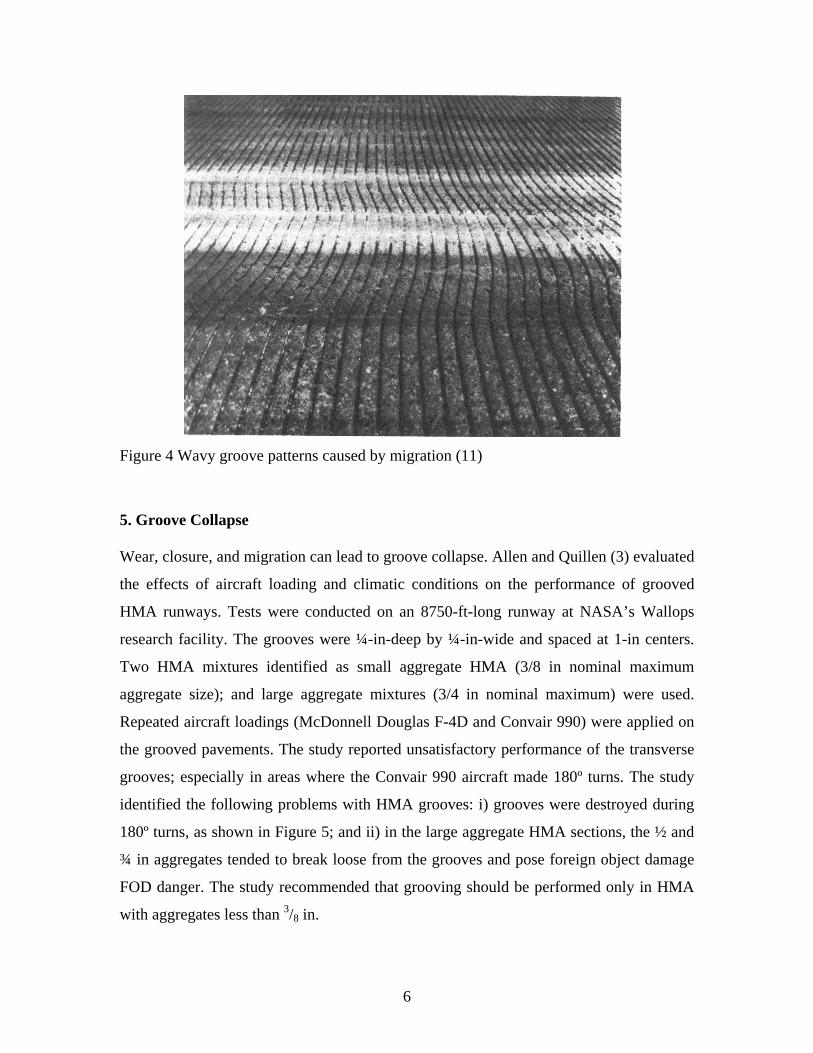
Figure 4 Wavy groove patterns caused by migration (11)
5. Groove Collapse
Wear, closure, and migration can lead to groove collapse. Allen and Quillen (3) evaluated
the effects of aircraft loading and climatic conditions on the performance of grooved
HMA runways. Tests were conducted on an 8750-ft-long runway at NASA’s Wallops
research facility. The grooves were ¼-in-deep by ¼-in-wide and spaced at 1-in centers.
Two HMA mixtures identified as small aggregate HMA (3/8 in nominal maximum
aggregate size); and large aggregate mixtures (3/4 in nominal maximum) were used.
Repeated aircraft loadings (McDonnell Douglas F-4D and Convair 990) were applied on
the grooved pavements. The study reported unsatisfactory performance of the transverse
grooves; especially in areas where the Convair 990 aircraft made 180º turns. The study
identified the following problems with HMA grooves: i) grooves were destroyed during
180º turns, as shown in Figure 5; and ii) in the large aggregate HMA sections, the ½ and
¾ in aggregates tended to break loose from the grooves and pose foreign object damage
FOD danger. The study recommended that grooving should be performed only in HMA
with aggregates less than 3/8 in.
6
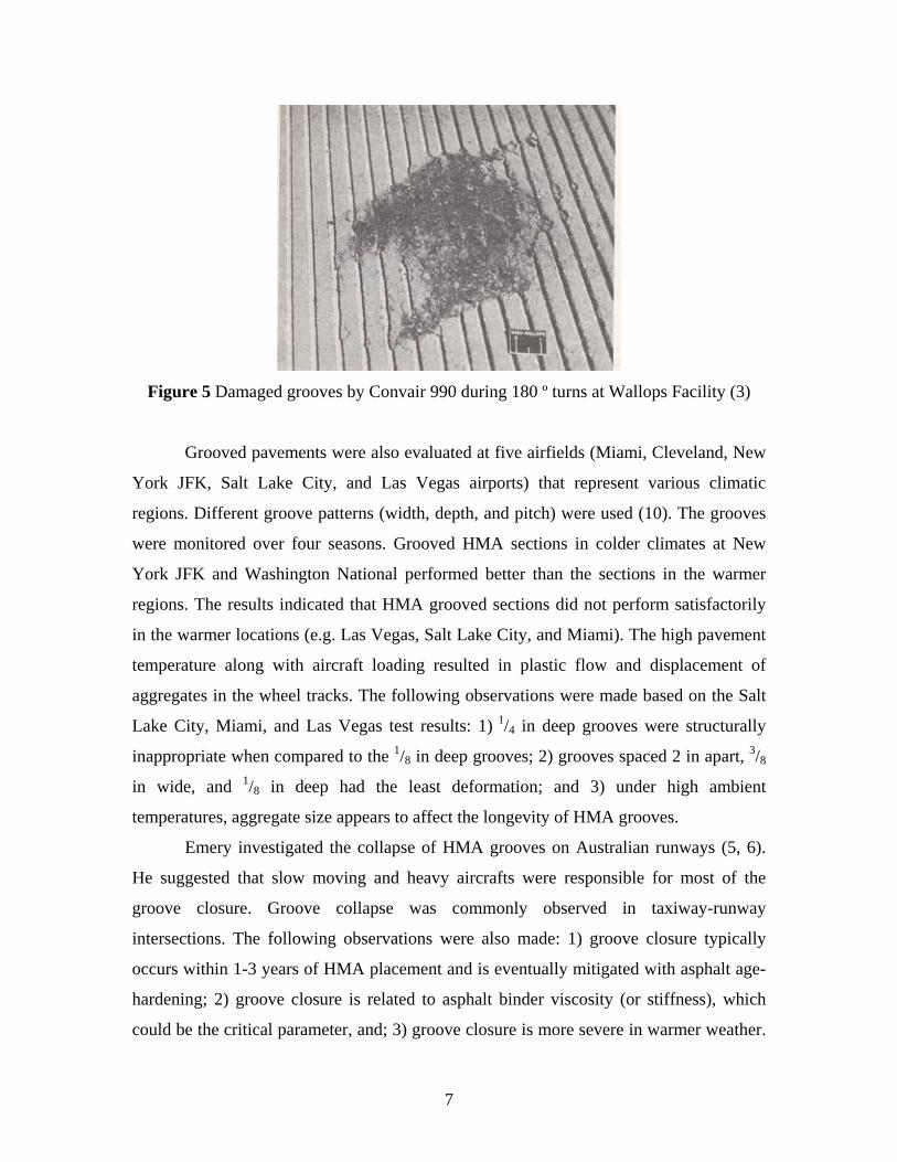
Figure 5 Damaged grooves by Convair 990 during 180 º turns at Wallops Facility (3)
Grooved pavements were also evaluated at five airfields (Miami, Cleveland, New
York JFK, Salt Lake City, and Las Vegas airports) that represent various climatic
regions. Different groove patterns (width, depth, and pitch) were used (10). The grooves
were monitored over four seasons. Grooved HMA sections in colder climates at New
York JFK and Washington National performed better than the sections in the warmer
regions. The results indicated that HMA grooved sections did not perform satisfactorily
in the warmer locations (e.g. Las Vegas, Salt Lake City, and Miami). The high pavement
temperature along with aircraft loading resulted in plastic flow and displacement of
aggregates in the wheel tracks. The following observations were made based on the Salt
Lake City, Miami, and Las Vegas test results: 1) 1/4 in deep grooves were structurally
inappropriate when compared to the 1/8 in deep grooves; 2) grooves spaced 2 in apart, 3/8
in wide, and 1/8 in deep had the least deformation; and 3) under high ambient
temperatures, aggregate size appears to affect the longevity of HMA grooves.
Emery investigated the collapse of HMA grooves on Australian runways (5, 6).
He suggested that slow moving and heavy aircrafts were responsible for most of the
groove closure. Groove collapse was commonly observed in taxiway-runway
intersections. The following observations were also made: 1) groove closure typically
occurs within 1-3 years of HMA placement and is eventually mitigated with asphalt age-
hardening; 2) groove closure is related to asphalt binder viscosity (or stiffness), which
could be the critical parameter, and; 3) groove closure is more severe in warmer weather.
7
The importance of asphalt binder characteristics on groove collapse was also reported by
Mosher (12). This finding was based on measurements of seven sections in five climatic
regions.
6. Mechanism of Groove Collapse
One mechanism of groove collapse involves plastic flow, which is similar to the
mechanism of rutting in ungrooved HMA surfaces. Emery (5, 6) suggested that the
mechanism of groove closure involved viscous flow. Microscopic analysis of HMA that
had flowed into grooves indicated that the binder still covered the aggregates. This
suggested a cohesive (or stiffness) deficiency rather than an adhesive failure. Based on
this mechanism of failure, it was suggested that groove closure should be related to
binder characteristics, which are function of temperature and time loading as well as age.
Another type of grove collapse involves groove edge breakage (5, 6). Groove
edge breakage is thought to be caused by horizontal stresses induced by aircraft tires. It
was reported that horizontal stresses up to 72 psi and up to 40 kPa could be induced in the
transverse and longitudinal directions, respectively, by a B747 aircraft. Repeated
application of this stress level on the unsupported groove edges could lead to edge
failure. Examination of broken groove edges indicated that the aggregates were still
covered with binder, suggesting a cohesive failure. Hence, groove edge breakage is
dependent on asphalt binder viscosity/stiffness. However, the mechanism of groove edge
breakage may be more critical under cold weather conditions than under warm weather
conditions. When subject to cold temperatures, the fracture resistance of asphalt binder is
decreased (mixture becomes more brittle).
In addition, other field conditions are believed to contribute to edge breakage:
age-hardening, freeze-thaw cycling, moisture effects, de-icing chemicals, and snow plow
damage.
Laboratory Tests for HMA Groove Collapse Evaluation
Since groove collapsing in HMA pavement is, in part, similar to rutting, laboratory test
methods used to evaluate rutting development in HMA could be considered to investigate
8
groove collapse. The standard FAA specifications for evaluating groove collapse are
based on the Marshall method (15). With FAA’s adoption of SuperPaveTM, new
mechanistic-based tests methods become readily available for rutting (and possibly
groove collapse) evaluation (7). Of the suggested evaluation methods the following two
are the most promising: The number of gyrations to maximum shear stress during the
gyratory compaction, parameter N-SRmax (3); the rut-depth versus number of loading
cycles from the Asphalt Pavement Analyzer (APA) (9, 13). In addition, full scale
accelerated testing can be used to evaluate the performance of grooves (14).
REFERENCES
1. AC 150/5320-12C (1997). “Measurement, Construction, and Maintenance of Skid-resistant Airport Pavement Surfaces.” Federal Aviation Administration.
2. Allen, C. R.; and Quillen, J. W. (1969). “Problem Areas Associated with the
Construction and Operation of the Landing Research Runway at NASA Wallops Station.” Pavement Grooving and Traction Studies, NASA SP-5073, Paper No. 8.
3. Anderson, M.; (2002). “Relationship of SPERPAVE Gyratory Compaction
Properties to HMA Rutting Behavior.” NCHRP # 478. 4. Duval, J.; and Buncher, M. (2004). “Superpave for Airfields.” Presented for
the 2004 FAA Worldwide Airport Technology Transfer Conference, Atlantic City, NJ.
5. Emery, S. J. (2005). “Bituminous Surfacing for Pavements on Australian
Airports.” 24th Australia Airports Association Convention, Hobart
6. Emery, S. J. (2005). “Asphalt on Australian Airports.” Australia Asphalt Paving Association Pavement Industry Conference, Surfers Paradise, Queensland.
7. Engineering Brief No. 59A (2006). Item P-401 Plant Mix Bituminous
Pavements (Superpave).
8. FAA (1969). “Environmental Effects on Airport Pavement Groove Patterns.” Engineering Center. Report - Federal Aviation Administration, Report No. FAA-RD-69-37.
9. Kandhal, P.; and Cooley, Jr. (2003). “Accelerated Laboratory Rutting Tets:
Evaluation of the Pavement Analyzer.” NCHRP # 508.
9
10. McGuire, R.C.; (1969). “Report on Grooved Runway Experience at
Washington National Airport.” Pavement Grooving and Traction Studies, NASA SP-5073, Paper No. 19.
11. Melone, R. (1979). “Surveys of grooves in 19 bituminous runways.” final
report /, Naval Air Engineering Center. Report - Federal Aviation Administration, Systems Research and Development Service ; FAA-RD-79-28
12. Mosher, L.G. (1969). “Results from studies of Highway Grooving and
Texturing of State Highway by several state Highway Departments. Pavement Grooving and Traction Studies, NASA SP-5073, Paper No. 27.
13. Pelland, J.R.; Gould, S.J.; and Mallick, B.R. (2003). “Selecting a Rut
Resistant Hot Mix Asphalt for Boston-Logan International Airport.” Airfield Pavements: Challenges and New Technologies, Airfield Pavement Specialty Conference, Las Vegas, Nevada.
14. Shilling, B.; (1969). “R.A.E. Aircraft Tests on Grooved, Open Graded and
Asphalt Runways in Great Britain.” Pavement Grooving and Traction Studies, NASA SP-5073, Paper No. 4.
15. “Standard Test Method for Resistance to Plastic Flow of Bituminous Mixtures
using the Marshall Apparatus.
10