Embed Size (px)
Citation preview
•• ••• •• • •. h:. ~7 ·')·3·A• •• Copy 60 0 C6Nt.1 bE~-rlt~~· ::. ~ f· N~~~ ~~ X-519 ~
Classification Changed t o [If, - l a s sified Effect '\'e In April 1963 h~ l , . ":. / Nf .),'\ CCN-3 By J,J.Car 11
TECHNICAL MEMORANDUM X-519
EFFECT OF VERTICAL-TAIL MODIFICATIONS ON THE STATIC
STABILITY CHARACTERISTICS AT A MACH NUMBER
OF 2.2 OF A SUPERSONIC VTOL AIRPLANE
MODEL HAVING A BROAD FUSELAGE
AND SMALL DELTA WINGS
By Ross B. Robinson and M. Leroy Spearman
Langley Research Center ~--------------, Langley Field, Va.
x $
CROFILM $
Ttus m2 t e:,la.l ; ",ntains ~.:fJrmallon a.!f • .:ct!:1q the nati·nal df':'!1.'llse if th~ Unit~d Stah!~ wlth:n tl1e mraning [the <p InaJ'~ ',',1,1' $. Title 13 , U.S . C ., &~s. 7J~ and nl.l, the transmission or r ..:-vdaU'1nv!',l,Thlch ina.'1.Y
n ~"11l' r t) ill 'H\&"uth .. r: ~~d pers:;n ,5 p r Jhlblled by law.
NA TIONAl AERONAUTICS AND SPACE ADMINISTRATION
WASHINGTON April 1961
CONFIDENTIAL
https://ntrs.nasa.gov/search.jsp?R=19630007289 2018-05-15T21:32:07+00:00Z
L
CONFIDENTIAL
NATIONAL AERONAUTICS AND SPACE A_INISTRATION
TECHNICAL MEMORANDUM X-519
EFFECT OF VERTICAL-TAIL MODIFICATIONS ON THE STATIC
STABILITY CHARACTERISTICS AT A MACH NUMBER
OF 2.2 OF A SUPERSONIC VTOL AIRPLANE
MODEL HAVING A BROAD FUSELAGE
AND SMALL DELTA WINCS*
By Ross B. Robinson and M. Leroy Spearman
J
An investigation has been conducted in the Langley 4- by 4-foot
supersonic pressure tunnel at a _ch number of 2.2 to determine the
effects of various tail modifications on the stability characteristics
of a model representative of a supersonic VTOL airplane. The original
model had a broad fuselage, small delta wings_ and twin vertical tails.
The tail modifications included a center-line vertical tail having the
same area as the original twin tails and the addition of twin ventral
fins.
The results for the configuration with the original tail indicated
an initially low value of directional stability Cn_ that decreased
rapidly with increasing angle of attack until directional instability
occurred above an angle of _.5 °. Changing to a single tail or adding
ventral fins resulted in an increase in directional stability at low
angles of attack. However, with increasing angle of attack, the con-
tribution of the single tail to Cn_ decreased more rapidly than that
for the original twin tails whereas the contribution of the ventral
fins remained essentially constant. As a result, the most effective
means of increasing the angle-of-attack range for positive Cn_ was
through the addition of ventral fins to the configuration with the
original vertical tail.
*Title, Unclassified.
CONFIDENTIAL _-
°
...... v
2 CONFI DENTIAL
INTRODUCTION
Among the types of manned aircraft currently being proposed are
those that combine the features of supersonic operation with the ability
to take off and land vertically (VTOL). Some of the configurations
being considered make use of lifting-fans in order to achieve the VTOL
characteristics. If these fans are installed in the body, the result
may be a rather broad, flat fuselage that might be expected to have a
pronounced effect on the aerodynamic characteristics of the vehicle.
Accordingly, an investigation has been undertaken in the Langley 4- by
4-foot supersonic pressure tunnel to determine the aerodynamic char-
acteristics of a model representative of a supersonic VTOL aircraft
having a broad fuselage, small delta wings, and twin vertical tails.
Results of the investigation at a Mach number of 2.01 (ref. i) indi-
cated that the original configuration had low directional stability.
An extension of the investigation has been made at a Mach number of 2.2
for which, in addition to the original configuration, tests were made
with a single vertical tail and with ventral fins. The results of this
investigation, with a limited analysis, are presented herein.
SYMBOLS
All data presented herein are referred to the body system of axes
except the lift and drag data which are referred to the stability sys-
tem of axes. The moment reference point is at a longitudinal station
corresponding to 65.35 percent of the body length.
CL llft coefficient, Lift/qS
C D
Cm
Cn
C Z
Cy
L/D
q
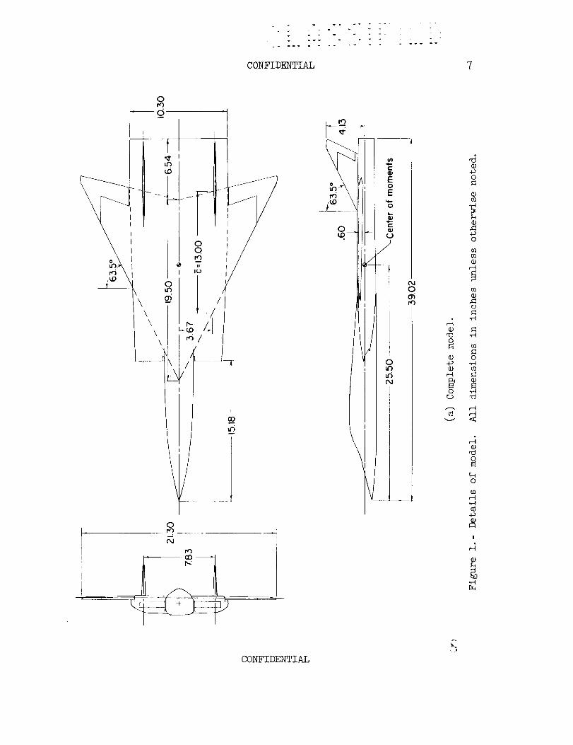
(See fig. l(a).)
drag coefficient, Drag/qS
pitching-moment coefficient,
yawing-moment coefficient,
rolling-moment coefficient,
side-force coefficient,
llft-drag ratio
Pitching moment/qS_
Yawing moment/qSb
Rolling moment/qSb
Side force/qS
free- stream dynamic pressure
O
CONFIDENTIAL
CONFIDENTIAL
S
b
c_
Cn_
CZ_3
Cyf?
wing area, 1.488 sq ft
wing mean aerodynamic chord, 1.08 ft
wing span, 1.77 ft
angle of attack, deg
angle of sideslip, deg
directional stability parameter
effective dihedral parameter
side-force parameter
MODEL AND APPARATUS
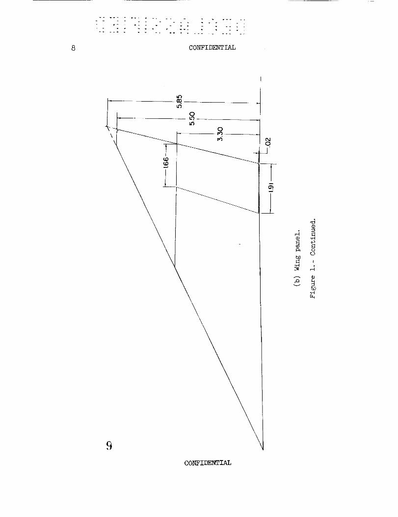
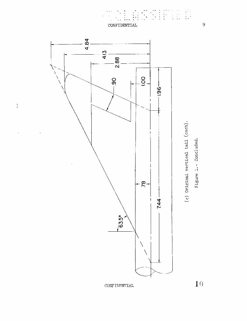
Details of the original model with twin vertical tails are shown
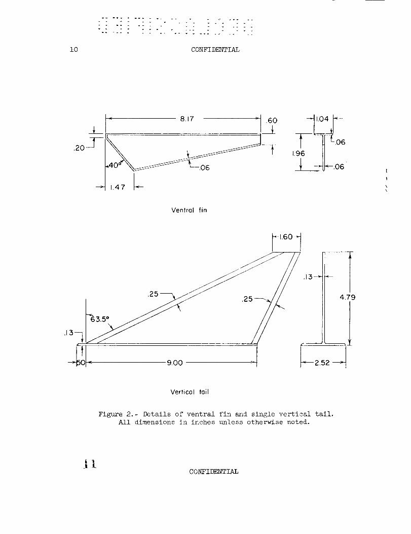
in figure i_ details of the ventral fins and of the sin_le vertical
tail are shown in figure 2. Geometric characteristics are given in
table I. The ventral fins were located at the same spanwise station
as the twin vertical tails. The body was designed to provide for an
internal flow system composed of twin horizontal-ramp inlets on the
sides of the body that were ducted to six simulated jet exits side by
side at the base of the body. All tests were made with 0.10-inch-wide
transition strips of No. 80 carborundum grains affixed 2 inches behind
the fuselage nose and at the 10-percent-chord stations of the wing and
tail surfaces. All control surfaces were set at zero deflection.
The model was mounted in the tunnel on a remote-controlled rotary
sting. Six-component force and moment measurements were made through
the use of an internal strain-gage balance.
TESTS, CORRECTIONS, AND ACCURACY
The tests were made in the Langley 4- by 4-foot supersonic pres-
sure tunnel with the following test conditions:
Mach number ........................... 2.2
Stagnation temperature, OF ................... i00
Stagnation pressure, ib/s_ in .................. i0
Reynolds number, based on _ .............. 2.44 × 10⁶
CONFIDENTIAL _-_j
4 CONFIDENTIAL
The stagnation dewpoint was maintained sufficiently low (-25 ° F
or less) so that no condensation effects were encountered in the test
section.
Tests were made for an angle-of-attack range of about -8° to 16°
at _o = 0° and for an angle-of-sideslip range of about -12 ° to i0° at_ and of about -8 ° to i° at _ = 4.6 ° , 9.1 °, and 13.6 ° .
The angles of attack and sideslip were corrected for deflection
of the balance and sting under load. The drag data have been corrected
for the effects of internal flow, base pressure, and balance chamber
pressure.
The estimated accuracy of the individual measured quantities is
as follows:
CL .............................. ±0.0004
CD .............................. ±0.0007
Cm .............................. ±0.0004
Cn .............................. ±0.0001
C_ .............................. ±0.0003
Cy .............................. ±0.0007
_, deg ............................ ±0.2
_, deg ............................ ±0.2
SUMMARY OF RESULTS
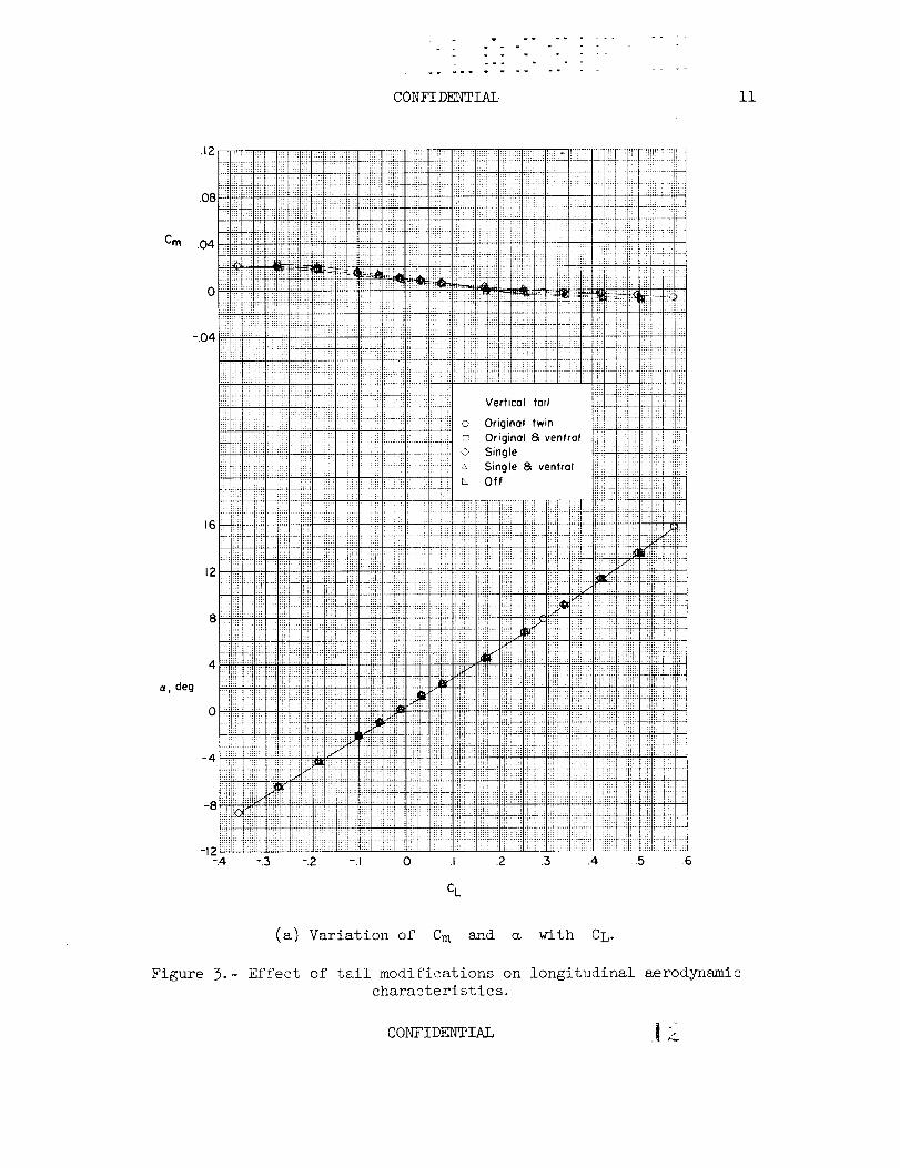
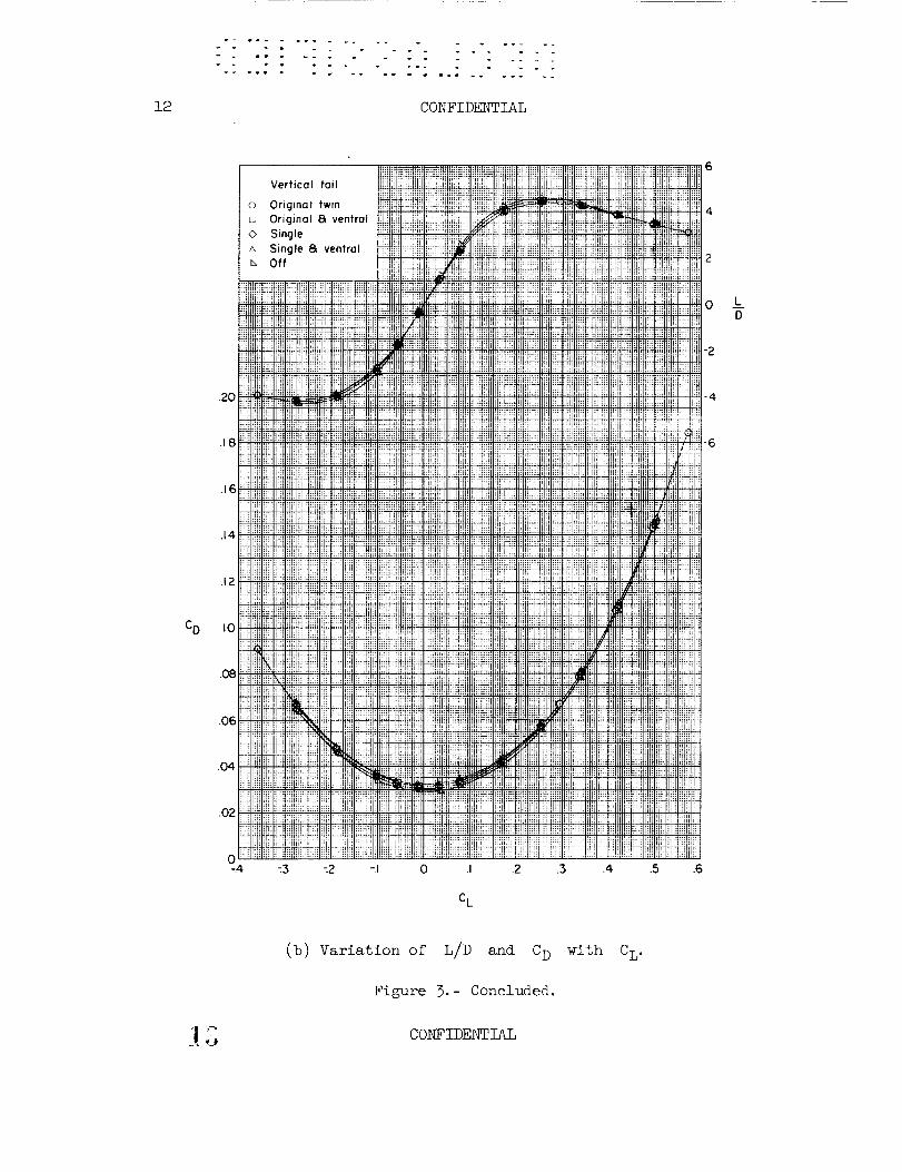
Modifying the vertical tail or adding ventral fins had little
effect on the longitudinal characteristics shown in figure 3 other than
to increase slightly the drag and reduce the lift-drag ratio.
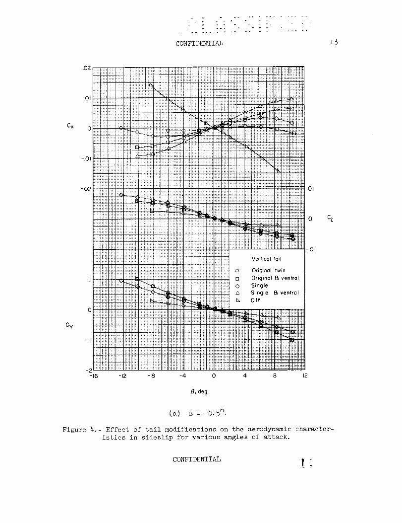
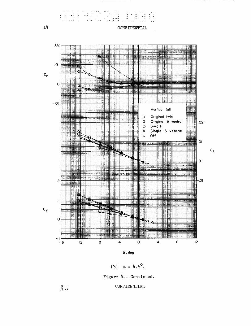
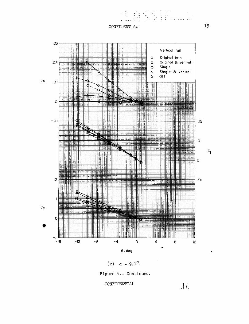
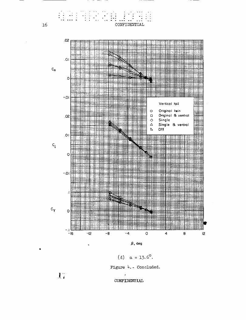
The aerodynamic characteristics in sideslip for various angles of
attack are shown in figure 4; the sideslip derivatives are shown in
figure 5. The configuration with the original twin tails indicates a
low value of directional stability Cn_ at _ = 0° that decreases
rapidly with increasing angle of attack until directional instability
occurs at _ = 4.5 ° (fig. 5)- Changing to a single tail or adding
ventral fins resulted in an increase in directional stability Cn_ at
low angles of attack. With increasing angle of attack, however, the
contribution of the single tail to Cn_ decreased more rapidly than
that of the original twin tails_ whereas the contribution of the ven-
tral fins remained essentially constant throughout the angle-of-attack
range. As a result, the most effective means of increasing the angle-
of-attack range within which positive directional stability could be
CONFIDENTIAL
ov--W w
CONFI DENTIAL 5
maintained was through the addition of the ventral fins to the configu-
ration with the original twin tails. As pointed out in reference i,
the rapid decrease in vertical-tail effectiveness with increasing angle
of attack is probably caused by a disturbance created by the inlet lips.
The existence of such an adverse flow field is indicated by the results
for the single tail wherein the effect of increasing the span of the
tail within the adverse flow field causes the tail effectiveness to
decrease even more rapidly as the angle of attack is increased so that
at the higher angles of attack the single tail is less effective than
the original twin tails.
Langley Research Center;
National Aeronautics and Space Administration,
Langley Field, Va., January 26, 1961.
REFERENCE
i. Driver, Cornelius, and Spearman, M. Leroy: Stability and Control
Characteristics at a Mach Number of 2.01 of a Supersonic VTOL
Airplane Model Having a Broad Fuselage and Small Delta Wings.
NASA TM X-441, 1961.
CONFIDENTIAL _,_
6 CONFIDENTIAL
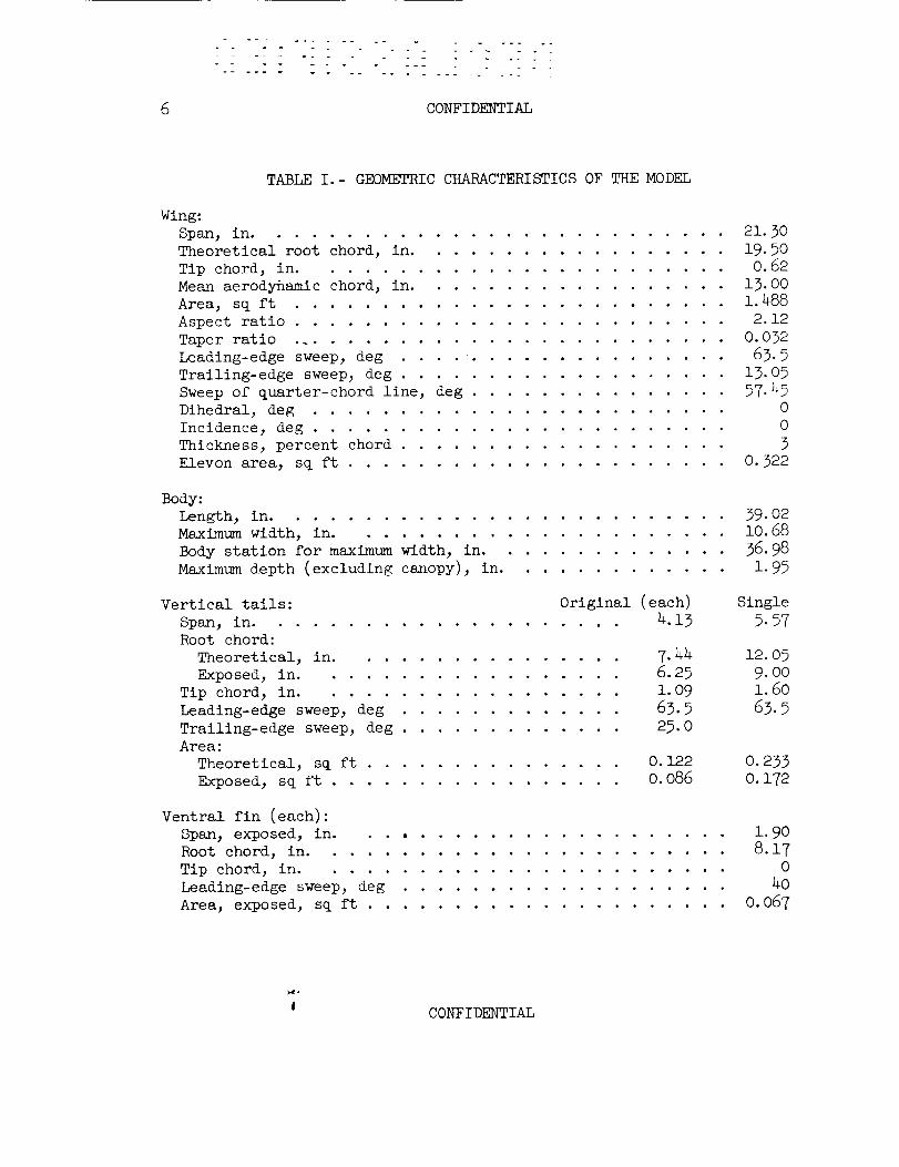
TABLEI.- GEOMETRICCHARACTERISTICSOFTHEMODEL
Wing:Span, in ............................ 21.30Theoretical root chord, in .................. 19.50Tip chord, in ........................ 0.62Meanaerodynamic chord, in .................. 13.00Area, sq ft ......................... 1.488Aspect ratio ......................... 2.12Taper ratio .......................... 0.032Leading-edge sweep, deg ................... 63.5Trailing-edge sweep, deg ................... 13.05Sweepof quarter-chord line, deg ............... 57.45Dihedral, deg ........................ 0Incidence, deg ........................ 0Thickness, percent chord ................... 3Elevon area, sq ft ..................... 0.322
Body:Length, in .......................... 39.02Maximumwidth, in ...................... 10.68Body station for maximumwidth, in .............. 36.98Maximumdepth (excluding canopy), in ............. 1.95
Original (each) Single4.13 5.57
Vertical tails:
Span, in .....................
Root chord:
Theoretical, in ................ 7.44 12.05
Exposed, in .................. 6.25 9.00
Tip chord, in .................. 1.09 1.60
Leading-edge sweep, deg ............. 63.5 63.5
Trailing-edge sweep, deg ............. 25.0
Area:
Theoretical, sq ft ............... 0.122 0.233
Exposed, sq ft ................. 0.086 0.172
Ventral fin (each):
Span, exposed, in. . ........ .......... 1.90
Root chord, in ........................ 8.17
Tip chord, in ........................ 0
Leading-edge sweep, deg ................... 40
Area, exposed, sq ft ..................... 0.067
CONFIDENTIAL
CONFIDENTIAL
O
I\
t
oO.
I I<._
ou_
0_
\\\
I
\ I/i_
I!I
IGO
oro
_J
00_
o
i
J
c
o
Po
©
o
%
-oo
ffl
G),--t
,_1 .,---I
_) o
o •
_ ,---t
o
o
ffl,---t
!
.,-4
CONFIDENTIAL
CONFIDENTIAL
9
o_D
h0
CONFIDENTIAL
CONFIDENTIAL
\\\\
CO
O
O
\\\
_DO_
r
CD
v
+_
O
0
_ ,©
,--t 0
bD .r--I
%
0
CONFIDENTIAL ]. !_,'i,
i0 CONFIDENTIAL
"_ 8.17 -_t 60 1.04tl
1.96
--'-U_-.06
Ventral fin
1.60 1
.I 3--_
900
4.79
_--2.52 --_
Vertical toil
Figure 2.- Details of ventral fin and single vertical tall.All dimensions in inches unless otherwise noted.
|CONFIDENTIAL
v ........
CONFIDENTIAL ii
.12,:......
!b! ililiii
.oeiii!iiiifill
cm04_u ........
!i!!_i!i!!!ii!ili!ii_
o iiii........
i!ii ili! iF!
!!ii i!i! ii!i-.04 ........ !i!!
_i ilii_i!iiN! :ii Niiiiii i!i! ii_:
_ill iili £!i
NU TUTN!!
i;i
1i ii ii_
_iR !iil ii
'_ ii!iiiiiiii!K ii! !;i;
8 NI_ Nil !iii
_-i!ii T
!N i! i_
o %!P '"_i:i_!: ,ii
iilii! i
Hi
H!I !:! }i:i
H_ ..........
-cr-
iHh2
i
ii2112L.i!I!!!i
UI ....
v T:
:_.i_..2:: :: :2 X
!i
b
!i:i i
i: ;i
] _N H
i i
MN:]i:1
i _11:Ni
o
c L
T _T_ TT'"i T• !i !!i ili
!i!_ii!i!i!!ii!:ii!_i_
Vertical tail
Original twin
.... !!i.... i_iiT -TYUT : N!
OrJginal B ventral _- ! -T_
Single
Single 8 ventral i!-T i H!
Off :, :: !i!ii<!iil ii! !N
iN Ui N TT _I--
:T-TTTUNI!'T U'! " "T! TT :TTT'U XUUTT i 11TT TT
!i1i ii_iiiEii! i i ili ii ii!i _E_!I !!i
221i_!_ i_ i2i.i 21!2 221;2;} _IIINI!_ilLII!!II! ii ili i_!il !ii iiii !ii
i '.; ! : i: _ ._ 11 : i_ !! H_i : i Lii ::i
! :i :i _ ii] ! EEi ] i£ : i[ _11
_ <i !!_i!!T!!i! Cii! _Ti!TI!I!!T:!!_!!i!i
i:i ii',!i!i ii!!i ', TI_, i!!!ii i!11!i _:_,!!ii
iii iiii..........i ::iiii .....i:,iili if: i: " ii ii!
i_ 1111P£ i/ 2 ? :I .... UI i! i_ !!
LiLEi_ iE21_ 2 _ £ 2i2122k £i iili2. LLi2112] ] h i : i ! i H i :!
XN 21£ :[: 2',i £i :: :i P, : ' I: : N
!! ii!ii:_;i}i _! !i:i!!__ [!;i';i
iliiiii,i!:: iii ....... Ii :::i]T!I]Ti]!=.T'_IT ; IIT:IT!]ii TIIT;iTT
.2 ,3 .4 .5
(a) Variation of Cm and _ with CL.
Figure 3.- Effect of tail modifications on longitudinal aerodynamic
characteristics.
CONFIDENTIAL ] 2
12 CONFIDE_YflAL
.20i
.14
CD .10
.5
4
o El.D
12
-4
-6
.6
CL
(b) Variation of L/D and CD with CL.
Figure 3.- Concluded.
o CONFIDENTIAL
. °
CONFIDENTIAL 13
On
Cy
,02 !!!i i::!
Tii ?:_it:iT _tt
'ill Z'I!!i! !i![
iF iii!
o ZI ;ill1::: :1!:
i[:i/11
t_t_t-.o_ !;?i!ti!
;.;2 i.,:
i:]: IX:
-,02 Z_! 11:::H_I i!i!
i!!:
:::: :11:
:!i! :!!:
iiil :_::
Hi: "!+T
lit: !''/
:H;i ;:;I
PV
?!;U !::;
!!il}i_:!.I :i_!! :m
_ii?i!xl
;_::: L:;[
01. : i::I
_ ...... L
7;: i:i;
-.i iiiii;ii;
Iii?
!!i!!H!
it i; I;H=2-16
:x:_::::: '!!!:':iii] iiliii i]iifl ::::I......................... • ,,.+
:.x :,i[':i Fii i............... : ...........................::: :::: ........ ".... x_ L_-+._ bd'i
_:_:!:ii :_i:i:ii i!:! iiii :_iii:i :i_!_ ili!! _ _N::;: i!i! ::: .... :::: ....
._m_,. _117 7q'7 _ 7:Tt- ........ . ........
:...................... : .......... _ i!ii !, ..... i!Ziii :x:lii_i! Z:'1[:: [:! :i[i_-_:+i :!tF L::!: ![]i i['!
........ :" ....... ..... :ii ....... i:ii!i ..... iiii ..... itli:ii }::i i::i iFi }i }i}! Fi} i}i} i i! ilii :iiii_ ZL Z._ .' _z" J _LZL _i_..L;g£ ........ ]'T : "1 ...... :1 :'I tti!ttt"
!!i i::'. i:ii :::: iiii:::::::; ili ilii i i[:iiii ii?iiiil ::::liFi' ]!i :": ;::i £XI i:,[:. :::: ]Z: .... i] .... gTZ::!ZZ'....:7:47r!2................................. ............ : ;: :::; :::;::::; L:;;I:H:iii} :_ 7-i_, [::i _2:" ,:' i:; "!'r z_'_; ,:._t.z "I trilt'i
.........ill'" :ll: :r nr [:!] [i:1 :[:: [':[ ::F11"i .... ::t: ::- :2!; 'rqt'"'
.... !! ! i ili ................ !l!i ii!_ .... :,,:: ::::!;:! ....if*..tl- !:'_ -,t. _-it
:1:_ :i;t :if: :::: :',; :::;
• _,* 4+, - .... u ........ _ ..... , ..............
:': "": :': ii_ ilii iFj iill i!i :;ii _-, =,-. ..i!i! :_-,_"m.. .... :!i! iii :ili izil :!i! :!]!
;::_ :;:; :m :_:: :::; _'-_,.., _i:-1:it lt't !1"t :1 .... it
11:t :_:::1;: :iU i:i! i:i'*_:i i;i. :_: _ :,r:'+:: }Ei_
ii:i ii!i !ii?ilii i!il ii5 ::i!:: i:!i !_ iFi :;_ 51_t_:1:: ,,-, ..... _" ti _t:t lIT :_h
_ LF! :!ii :lk !:i] :..i .... if? :iii ............. L'!;'.;i i_:;:i:_ :!_ i:_iti_ !:;_!:: :Ft l:;t !; !!;! fi?i:'_:=!_!i
i} ill .... "=*+l:}i 1:;_ _,._ mr -. FU :¢!i ¢:t¢ .. dt m_,
im _:l :!::I :; ...... :::* ,:: :h: '.2_ iii "'_'__i:_.:........!:;i _:'.t i;:i !{}_ ;i_: i:!I I;'-_ ii: :FI _::: ',i:* _i......... i!!i
................................ ii!::;il_!i_i>r :ii:i_:i :r-,u _:__, :,iit ,;,iil i!fi-12 -8 -4 0
/_, deg
2Z:L "
t":
7(]: :i_
..... :7! "t
IZ ._,, i!ii
_, :,: iili W:
!ii ii!! !iii:!i_i !ii! <r _::_! :4;_:_i i_iliLi":::,_ii _ii!_<_iii:-:,:....:il t'11 'i ,111! ...... 11 ...... tt _ 't+r
-}!:, :-rx _-_x_x
ili ,i _]tTt -t*ff
_i_ii}! ":",ii::iiiii"* ......+::
r!:_t:!,,
Vertical toil
O Original twin
[] Original E_ ventral
O SingleA Single _ ventral
Ix Off
+;:i t_t:;_ ii_ _'_
4
.01
8 12
0 Cl
-.01
Figure 4.-
(a) _ = -0.5 °.
Effect of tail modifications on the aerodynamic character-
istics in sideslip for various angles of attack.
CONFIDENTIAL I t
14
_°
CONFIDENTIAL
C n
Cy
0
0
-12 8 -4 0 4 8 12
_, deg
0
(b) _ = 4.6°.
Figure 4.- Continued.
CONFIDENTIAL
CONFIDENTIAL 15
Cn
Cy
9
.O3
.02
.01
-.01
.Z
NZt it:; ::_:; ._+-. _.r_
tl
!iii :i:ii:::: ::i: :u_::=::=_.
#!_[HCH !+it °!ft
_ L'at !
:L+:
:f.; ::li:kffii:'d:i::f H:i ii:i :r:_ :::;::::: :_z::-: .... r'*_ _
........ t'it , _+t! tPf _+ L*_I .... I t_'L**'LL21
Vertical tail
0 Original twin
[] Original _ ventral,0 Single
A Single _ ventral!i o,,
"÷-z ii
-16 -12
t :iH _:e_+H ..
... i. ii. ....................................... , ,, q,,
:_ :!:L L_ L :_: _: :d, _ I: r+_
,_,,T.,,-._-_ _ ii Ii _;i, i i i [, i ;t_!il iJ i ;j[ij _,tt!!!, ,t !! !,1!!:[ i;i [i i,i
Ht t¢ _'*+t _ ............
_',
-8
- ,-t -'-_ :_ ' ll':i[':H':llllli',l',ll[: [',[l]
]i'!!!!!!Hi[ii]JJ [[iil]i[ii[!!}!]}}!!i!![[!!iii.... i l N 11i i [':', [ '.; ; ;i ; [',:[ ; iil! I I ! tt !
r _ ]}[:=:illl_l l,_[]l[llgllll III_,IIIIII_111 1
-4 0 4 8
m
B, deg
.O2
.01
0
-.01
12
C_
(c) _ = 9.1 °.
Figure 4.- Continued.
CONFIDENTIAL
3_6
..... = ....... _ ....
CONFIDENTIAL
Cn
C_
Cy
0
-.01
.02
.01
0
-.01
.I
0
Verlicol loll
Original twin
Original _ ventral
Single
Single 8, venlrol
Off
-12 -8 -4 0 4 8 12
B, deg
(d) o_ = 13.6 °.
Figure 4.- Concluded.
CONFIDENTIAL

__ " ..... _'_, ..... --
CONFIDENTIAL 17
,002
.001
0
Vertical toil
-- Original twin
Original 8E ventral
Single
Single a ventralOff
-.001
-.002
-.001
CzB
-002
=003
0
Cy/_ -.01
-.02-8 -4 0 4 8 12 16 20
a, deg
Figure 5.- Effect of tail modifications on the static sideslip
derivatives.
NASA- Langley Field, Va. L-1459 CONFIDENTIAL -_ 2)
..... om m v vl _ m_m
•• • • • • • • ••
••• • • • ••• •• • • • • • ••• • ••••
• •• • • • •• • ••• • • • ••
• •• ••• • • • • • •• • • • •• • •
• ••• • • • •• • • • •••
•• • • • • • • ••
•• • • • • • • ••
••• • •• • •••
• •••••• • •• • • ••• • • ••• • • • •• t:ON FEOEml:}\L • ••• • • • •• •• • • ••••• ••• • •
CON FI DENTIAL