Embed Size (px)
Citation preview

PROMECAM
HYDRAULIC PRESS BRAKES
I.T.S
TECHNICAL MANUEL
63, Rue de Strasbourg 93206 Saint Denis Cedex 1 - FRANCE Tel: 161 4821 60 06 TELEX: 232717 Telec. : 161 48 22 61 57

...
.J
,.~
, ....... , ._".....-.

PROMECAM
CONTENTS
1 • GENERAL INTRODUCTION .............................................................. 1 I 2
2. ~AI=E:T" •••••••••••••••••••••••••••••••••••••••••••••••••••••••••••••••••••••••••••••••••••••• 1 16 2 - 1 CONFORMITY ................................................................................. 1 1 6 2 - 2 SAFETY INSTRUCTIONS FOR PRESS BRAKES ...................................... 1 1 6 2 - 3 RULES FOR SAFE OPERATION .......................................................... 2 / 6
3 - IN~TALLATION REQUIREMENT~ •••••••••••••••••••••••••••••••••••••••••••••••••••••• 1 I 4
3 - 1 ELECTRICAL CONNECTION ................................................................ 1 /4 3 - 2 PNEUMATIC SYSTEM ......... '" ............................................................ 4 1 4
4 '. ~rTE AND ENVIRONMENTAL PREPARATION ....................................... 1 / 2
5 - IN~TALLATION AND TAKING DELIVERY ••••••••••••••••••••••••••••• ,.. ............. 1 I 4
5 - 1 INSTRUCTIONS BEFORE HANDLING AND INSTALLING ............................ 1 / 4 5 - 2 HANOLING ..................................................................................... 2/4
6 • LEVELING 01= THE MACHINE ••••••••••••• " ............................................. 1 I 2
7 • PUTTING MACHINE INTO ~ERVICE •••••••• u ......................................... 1 I 2
8 • OPERATING AND ~TORAGE CONDITIONS ••••• " ••••••••. ' ••••••••••••••••••••• an""~ 1 1 2
9 - TECHNICAL DESCRIPTION ••••••••••••••••••••••••••••••••••••••••••••••••••••••••••••• 1 I 4
9 - 1 MECHANICAL STRUCTURE .................................................................. 1 / 4
9 - 2 MECHANICAL CONNECTIONS ............................................................... 2 I 4 9 - 3 Y AXIS MECHANISM ........................................................................... 3/4 9 - 4 SPEED SEQUENCE ............................................................................ 4 / 4
10 - REAR GAUGE BLOCKS •••••••••••••••••••••••••••••••••••••••••••••••••••••••••••••••• 1 I 4
1 0 - 1 DESCRiPTION ................................................................................ 1 1 4 10 - 2 REAR GAUGE ASSEMBLY MECHANISM ON MODEL 412 ......................... 2/4 10 - 3 REAR GAUGE ASSEMBLY MECHANISM ON MODEL 600 ......................... 3/4
11 - LOCAT~ON OF CONTROL DEVICES.n •••••••••••••••••••••••••••••••••••••••••••••• 1 112
11 - 1 ON THE ELECTRICAL CABINET .......................................................... 1 / 12 11 - 2 START-UP ..................................................................................... 2/ 12 11 - 3 DESCRIPTION OF CYCLES ................................................................ 2 / 12 11 - 4 ON NC CONTROL PANEL (OPTION) ................................................... 4/12 11 - 5 USE OF THE LIGHT GUARD .............................................................. 5 112

PAOMECAM
12 - MB NUMERICAL CONTROL (OPTION) ••••••••••••••••••••••••••••••••••••••••••••• 1 / 6
12 - 1 DESCRIPTION· ............................................................................... 1 / 6 12 - 2 GENERAL CHARACTERISTICS OF THE MB NUMERICAL CONTROl. ......... 1 / 6 12 - 3 MANAGEMENT OF AXES .. " .............................................................. 2/6 12 - 4 OPERATING DIAGRAM ..................................................................... 3 / 6 12 - 5 CHARACTERISTICS OF COMMAND AND CONTROL PANEL BOARDS ......... 4 / 6
13 - BENDING AND PUNCHING TECHNIQUES .......................................... 1 / 8
13 - 1 AIR BENDING ................................................................................. 1 /8 13 - 2 COINNING ..................................................................................... 2/8 13 - 3 PUNCHING TECHNIQUE ................................................................... 3 / 8 13 - 4 MOUNTING TOOLS .......................................................................... 4,/8
14 - USE WITHOUT NUMERICAL CONTROL •••••••••••••••••••••••••••••••••••••••••••• 1 I 4
14 - 1 PRELIMINARY OPERATIONS .............................................................. 1 / 4 14 - 2 IMPORTANT RECOMMENDATIONS ....................................................... 1 /4 14 - 3 TURNING ON AND OFF ....................................................... , ............. 1 /4 14 - 4 MUTE-LEVEL SETTING ..................................................................... 1 / 4 14 - 5 PRESSURE REGULATOR SETTING ...................................................... 2 /4 14 - 6 HYDRAULIC GAUGE BLOCK CONTROL SETTING ................................... 3 / 4
15 - USE OF NUMERICAL CONTROL (TYPE MB) •••••••••••••••••••••••••••••••••••••• 1 / 14
15 - 1 PRELIMINARY OPERATIONS .............................................................. 1 / 14 15 - 2 OPERATION ................................................................................... 2 / 14 15 - 3 USE IN TEACHING MODE ................................................................. 8/ 14 15 - 4 SELF-DIAGNOSTiC .......................................................................... 9 / 14 15 - 5 ERROR MESSAGES ....................................................................... 11 / 14 15 - 6 TROUBLE-SHOOTING ..................................................................... 12/ 14
16 - NUMERICAL CONTROL CUSTO,MIZATION ........................................ 1 I 2
1 6 - 1 METHOD OF ACCESS ...................................................................... 1 / 2 16 - 2 KEY VALUES .................................................................................. 1 / 2 16 - 3 METHOD OF 'CHECKING ................................................................... 2 / 2 16 - 4 METHOD OF WRITING ..................................................................... 2 / 2
17 - PROGRAMMING •••••••••••••••••••••••••••••••••••••••••••••••••••••••••••••••••••••••••• 1 /18
17 - 1 PROGRAMMING OF A PART .............................................................. 1 / 18 17 - 2 PROGRAMMING OF BENDS ............................................................... 3 / 18 17 - 3 FINDING PINCH DIMENSION .............................................................. 5 118 17 - 4 FINDING BENDING DEPTH VALUE ....................................................... 9 / 18 17 - 5 PRODUCTION ............................................................................... 17 / 18
18 - MAINTENANCE ••••••••••••••••••••• 11 ••••••••••••••••••••••••••••••••••••••••••••••••••••• 1 I 6
18 - 1 MACHINE MAINTENANCE .................................................................. 1 / 6 18 - 2 REAR GAUGE ASSEMBLY MAINTENANCE ............................................. 3 / 6 18 - 3 ADJUSTABLE INTERMEDIATE SETS ..................................................... 5 /6 ~

PAOMIiCAM
1 - GENERAL INTRODUCTION
This document is designed to facilitate the handling, placing operations and connection t9 the electricity and compressed air supply networks of your ITS or ITPS hydraulic press brake (Figure 1.1).
This publication covers the following models:
ITS 50/12 ITS 50/20 ITS 80/25 ITS 103 ITS 125/30
List of available versions:
On ITS 50112 Type 412 rear thrust block with:
X axis or X axis + R1, R2
ITS/ITPS - GENERAL INTRODUCTION
On ITS 50/20, 80/25, 103, 125/30 Type 600 rear thrust block with:
- axis X or - axis X + R1 ; R2 au X axis + R1, R2 + 21,22
1 -112

.MADA PROMECAM
TABLE OF MACHINE CHARACTERISTICS DESIGNATION UNITES 50/12 50/20 80/25 103 125/3
NOMINAL POWER KN 500 500 800 1000 1250 DISJUNCTION KN 10 8 20 18 18 MAX BENDING LENGTH mm 1250 2000 2500 3000 3100 TABLE LENGTH mm 1200 2000 2500 3000 3100 TABLE WIDTH mm 60 60 60 90 90 WORKING TOP HEIGHT mm 960 960 960 960 960 INTAKE mm 370 370 370 370 370 STROKE mm 100 100 100 ~OO 100 GOOSE NECK mm 400 400 400 400 400 SIDEPLATE ENTRY mm 1020 1690 2160 2600 2600 MAXI PRESSURE M.Pa 31,S 31,5 25,2 51,5 26,3 NB. OF CYLINDERS 1 1 2 2 3 OIL CAPACITY Liters 45 45 70 85 110 50 160 Hz INST. POWER Kw 6,5 6,5 9,5 11 13 INST. POWER Kw 4,5 4,5 7,5 9- 11 50 Hz APPROX. SPEED mm/s 85 85 85 85 85 60 Hz APPROX. SPEED mm/s 82 82 82 82 82 50/60 Hz WORKING SPEED mm/s 10 10 10 10 10 50/60 Hz RETURN SPEED mm/s 80 80 80 80 80 No. OF CYCLES 4 4 4 4 4 OVERALL HEIGHT mm 2030 2180 2200 2325 2400 OVERALL LENGTH mm 1700 2500 2860 3300 3300 OVERALL WIDTH mm 1745 1745 1880 1930 1940
WEIGHT Kg 2600 3300 4600 6000 7200 WEIGHT GAUGE Kg 175 330 410 430 430 No.OF ADJUST. INTERS 6 10 13 15 15 ADJUSTABLE INTERS mm 120 120 120 120 120
TOOLS Width: 835 1 2 3 4 4 Width: 415 1 1
AS AMADA PROMECAM'S POLICY IS ONE OF CONTINUOUS DEVELOPMENT, ALL SPECIFICATIONS ARE SUBJECT TO CHANGE WITHOUT NOTICE
,
1- 2/2 INSTALLATION MANUEL - ad: 03/90
I-,J

PROMECAM
2 - SAFETY
2 .. 1 - CONFORMITY
Press brakes are shipped from the factory with basic safety equipment including:
A double foot pedal (close/open).
A switch-operated mode selector.
Lateral protection
Back protection
SeH-supervising electrical and hydraulic circuits
Optional: equipment for a second operator.
2.2 - SAFETY INSTRUCTIONS FOR PRESS BRAKES
Do not use, adjust or undertake any action on the machine without first having read the instructions.
Observe all safety instructions when using this press.
Do not place hands between tools.
Do not place hands between tools to adjust the back gauge.
Do not operate press if side or rear safety panels are not in place.
Do not remain between the protective pieces and the danger area.
Before any operation make sure that :
- all protective devices are in place - the operating cycle is correct for the work to be done - nothing is interfering in-between the tools - there is open access to the various parts of the machine - the floor around the machine is free of grease, oil or water.
Make sure that gloves are worn during operation
'TS/ITPS - SAFETY 2-1/4

PROMECAM
2.3 - RULES FOR SAFE OPERATIC)N
Use pliers or any other tooling to help bend small dimension or small width parts. Never place your fingers near the punches.
Remove your hands form the part to be bent after the latter has been pinched between the tools. Otherwise this might result in serious injuries.
Make sure that the operator removes the punches and the tooling in compliance with the procedure described in this manual. Make sure that the motor is stopped at that moment.
2-2/4 INSTALLATION MANUEL- 00:03/90

PROMECAM
Never place your hand between the part and the rear gate while operating your machine.
Never place any part of your body between the die and the punch during a bending operation.
Never try to support the end of the workpiece by supporting it on both sides of the beam.
ITS/ITPS • SAFETY 2·3/4

PROMECAM
Take care of sudden rising of the beam. Make sure that the part is bent slowly if it is large.
,
Make sure that the tools are used within the prescribed safety_pressures The tools might break into pieces and be scattered if the safety pressure is exceeded.
If two operators are to work on the machine, make sure that use of the pedal is limited to the main operator and that the pedals are actuated only after receiving a sign from the other operator; the same caution should be taken for dual control operation.
2-4/4 INSTALLATION MANUEL- ed:03/90

PROMECAM
3 - INSTALLATION REQUIREMENTS
3.1 - ELECTRICAL CONNECTION
The proper operation of an electrical system depends on the quality of the power supply, it should be
stable and free of disturbances.
Installation should be planned and carried out so as to meet currently applicable regulations.
3.1.1 - GENERAL MAINS CHARACTERISTICS
Power supply
Peaks
Harmonics
Frequency
Electrical power supply
Three-phase current (depending on mains) -10% to +10% in stable rating -20% to +20% transient rating (20 ms)
50% of nominal value during maximum of 5 ms
50/0 maximum
50160 Hz (depending on mains)
Specialized line to be exclusively reserved for the system from the general LOW VOLTAGE board. The whole system is powered by a single 3-phase cable with earth (possibly also with neutraQ
3.1 .2 - EARTH
In pursuance with applicable standards any equipment which is not provided with double installation requires an earthing connector. This is also required at operational level and for floor earth drainage of electrical noise interferences.
- The cross section of the earthing conductor must be sufficient. For maximum security earthing distribution should be made in a STAR CONFIGURATION beginning from the power board terminal. As in any other electrical installation the quality of the ground connection should be verified periodically by an approved organization.
- The earthing resistance measured at the bar closest to the earth terminal should be less than 6 ohms.
- The earthing conductor (green and yellow), is reserved exclusively for the system. It is connected directly to the earthing bar.
ITS/ITPS - INSTALLATION REQUIREMENTS 3 ·114

laMADA PAOMECAM
3.1.3 - INTERFERENCES RELATED TO MAINS AND ENVIRONMENT
IMPORTANT
DO NOT UNDER ANY CIRCUMSTANCES WELD A PIECE TO THE MACHINE. YOU COULD DAMAGE THE MECHANICAL, ELECTRICAL AND ELECTRONIC COMPONENTS.
The distribution network introduces some interferences (micro-powercuts, frequency drifts, harmonics, interferences etc ... ). These might be detrimental to the correct operation of the system. So, some electonic components might therefore be submitted to abnormal or excessive voltages and currents causing their damage beyond repair. It may be necessary to provide for some adapter elements without galvanic connection to mains (voltage stablizer, rectifier, converter, transformer, insulation transformer etc ... ). If required the quality of this electrical power supply should be checked by an approved organization and analysis of the results should determine the required equipment type. The following interference must be considered as disturbing for any electronic system:
Electrostatic discharges
These are very critical in an environment with relatively low ambient humidity : people or moving assemblies often create a discharge of several thousand volts by touching a door handle or a metal upright or, even worse, the chassis. Therefore, it is necessary to provide for an antistatic environment (anti-static carpet for example).
Transient on mains power supply
Transient are electrical noise pulses propagated along the mains leads which may affect system operation. Their origin may be internal: motor, lift, refrigerator, air conditioning unit, fluorescent tube or any other machine generating mains noise : or external : stormy weather, neighbouring plant ... Transient specifications accepted by the system are 50% of the nominal voltage for a maximum du ration of 5 ms.
Stormy weather
The charges accumulated in stormy conditions result in transient on the mains or on the connecting cables.
Magnetic fields
A variable magnetic field induces a voltage into a closed circuit creating considerable interference. Cathode ray tubes are sensitive to magnetic fields. Their sensitivity is materialized by faulty chromatics of the image or of its geometry. Tl1ese are therefore fitted with a protective shielding.
Medlum- or high-frequency electro-magne!tic radiation
This interference type may be the origin of a large number of problems in the systems (operational amplifiers, DP memory). Generally, the ma~Jnitude of such disturbances depends of the radiation duration and intensity. They may be due to RADAR installations (near airports for instance) or to radio frequency transmitters (military, civil, Police, Stations, FM .. ) or even to defective or badly filtered discharge tubes. Walkie-talkies can pll'Oduce the same effect when used near input channels. The reference value to be taken into consideration corresponds to an 0.2 to 0.5 VIM field in a frequency range of 10KHz to 1 GHZ.
3-2/4 INSTALLATION MANUEL -ed:03/90
-,'
PROMECAM
3.1.4 - CHARACTERISTICS OF THE MACHINE POWER SUPPLY CABLE
MODELS POWER CABLE (in tons) (section in mm2 for a line ~ 20 meters)
50 2.5
80/100 4
125 6
We recommend the installation of a circuit protector or breaker at the head of the line.
Cable may be led in from the floor (fig 3.2) or on an aerial line (fig 3. 1).
The power cable should, in no event, pass through the control box or channel located on its front.
The main switch located in the electrical cabinet is designed to receive up to three safety padlocks. We advise that you immediately install a lock so as to prevent untimely power-up.
Aerial line Fig 3.1 Floor line Fig 3.2
3.1.5 - CHECKING THE POWER SUPPLY VOLTAGE
Check your mains voltage. This value should be specified to the AMADA agent who will connect and start your machine.
ITS/ITPS· INSTALLATION REQUIREMENTS 3-3/4

PROMECAM
3.2 - PNEUMATIC SYSTEM
Pneumatic installation is required if your machine is fitted with the "all or nothing" traverse motion.
- Network pressure: 6 bars + 1 - Maximum rate - Flow: 5 liters/minute under 6 bars
COMPRESSED AIR SUPPLY DIAGRAM
TAPPING
_~ ____ --TO MACHINE
Fig 3.3
For reference:
Your machine is fitted with a "filter - pressure~ valve - lubricator" conditionning assembly (if the "all or nothing" traverse motion system ;s installed)..
Periodic control
You should check the levels in the filter and lubricator elements regularly.
Top up when unpressurized using one of the following lubricants:
TYPE OF OIL VISCOSITY RANGE
BP ENERGOL HLP1 0 Class ISO VG 10 ESSO Spinesso 10 1803448 SHELL TELLUS C1 0
3-4/4 INSTALLATION MANUEL - ed : 03190

PROMECAM
4 - SITE AND ENVIRONMENTAL PREPARATION
Press brakes installation requires a stable, rigid ground surface.
Flooring in the work area should be a 50 mm thick concrete slab, with a plane surface (maximum tolerance 2 mm per metet'). For the installation conditions please consu It our technical department.
Access to the press shou Id be provided on all four sides :
- At the back leave a space of approximately 1 meter for maintenance operations and adjustments.
- On at least one of the sides provide for a space slightly above the maximum bending length, so that lateral withdrawal removal of some parts is allowed on the whole press brake lengh (dimension A, Figure1).
H
0 0 0 .,-
l'
I"'"
A +200
-- +100 ~ - .
[!!J ~ ~B~ A ~ .. --
Please see chapter on characteristics for other specifications.
MACHINE A 8
50/12 1250 990 50/20 2000 925 80/25 2500 910 103 3000 890
125/30 3100 850
ITS/ITPS - SITE AND ENVIRONMENTAL PREPARATION 4 -112

PROMECAM
4-2/2 INSTALLATION MANUEL - ed: 03190
PROMECAM
5 - INSTALLATION
5.1 -INSTRUCTIONS PRIOR TO HANDLING AND INSTALLATION
5.1.1 - PREPARATION OF THE INSTALLATION FLOOR
Once the location is prepared, carefully sweep the area to be occupied by the press.
5.1.2 - FORBIDDEN OPERATIONS
In no case should handling accessories (slings, hooks, straps, etc.) be attached to the following components:
- Upper beam - Lower beam - Electrical cabinet - NC Cabinet - Bending Depth control (ITS) - Pressure limiter (ITS) - Mechanical protectors on: - Goose neck - back of machine - Hooding - Back gauge
Please see section 5.3.2 to identify the areas recommended for floor support.
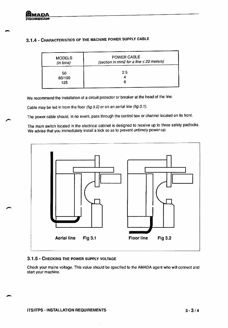
IMPORTANT
CERTAIN PARTS OF THE MACHINE (ESPECIALLY ITS NUMERICAL CONTROL IF FITTED) ARE NOT DESIGNED TO WITHSTAND THE WEIGHT OF A MAN WITHOUT DEFORMATION. THEY ARE INDICATED BY A TAG AS ILLUSTRADED ON FIG. 5.1
Figure 5.1
ITS/ITPS -INSTALLATION 5-1/4

PROMECAM
5.2 - HANDLING
5.2.1 - BASIC PRINCIPLES
The lifting efforts should only be applied at the slinging points provided for this purpose (Fig. 5.2).
LOAD DISTRIBUTION RELATED TO SLING ANGLE
6 Example A : (450 angle) 50% of load weight on each sling arm.
b Example B : (90 0 angle) 75% of load weight on each sling arm.
DO NOT EXCEED AN ANGLE OF 90°.
TYPE CENTRE OIF GRAVITY E WEIGHT IN KG
X V Z
50/12 810 670 525 30 2600 50/20 915 670 710 30 3300 80/25 1005 670 700 40 4600 103 1120 670 770 40 6000 125/30 1140 670 770 45 7200
Add approximately 500 Kg if your machine is fitted with a numerically controlled back gauge.
5-2/4 INSTALLATION MANUEL - ad :03/90

PROMECAM
5.2c2. - HANDLING ACCESSORIES
The handling operations are to be performed as follows:
a) Use lifting means such as travelling bridges or cranes. .' Use the slinging point (40 mm diameter holes on each upright). These holes can directly receive the shackles where the lifting slings will be secured.
b) If no appropriate lifting equipment is available the press may be moved on small tractors (Fig 5.3).
In this case carefully campi y with the allowed bearing points:
'%%2] forbidden areas Allowed areas
IMPORTANT
Fig 5.3
Fig 5.4
ANY HANDLING OR SELECTION OF BEARING/ANCHORING POINT OTHER THAN THOSE SHOWN ON THE ABOVE DIAGRAMS ARE FORBIDDEN. ANY INCIDENT RESULTING FROM NON-COMPLIANCE WITH SUCH INSTRUCTIONS MAY RESULT IN SUSPENSION OF THE GUARANTEE.
ITS/ITPS - INSTALLATION AND TAKING DELIVERY 5-3/4

PROMECAM
5-4/4 INSTALLATION MANUEL- ad: 03/90

PROMECAM
6 - LEVELLING OF THE MACHINE
carefully follow the procedure given below to level your machine correctly.
Provide two 150 X 150 X 5 mild steel shims.
1
Fig 6.1
According to the date on which the machines are manufactured, screws refs. 1 can be located either inside or outside the frame.
With the machine laid directly on the floor, test its horizontality with a spirit level placed successively in N1 and N2.
A 2 mm per metre level fault (in N1 and N2) is acceptable.
IMPORTANT
THE MACHINE SHOULD NEVER REST ON OTHER SUPPORTS THAN C1, C2, C3. SCREWS REF 1 SHOULD NEVER BE USED TO CORRECT THE LEVEL. THEIR ONLY TASK IS TO ENSURE THE TRANSVERSE STABILITY OF THE MACHINE. FOR SPECIAL INSTALLATION CONDITIONS REFER TO OUR TECHNICAL DEPARTMENT.
ITS/ITPS - LEVELLING OF THE MACHINE 6 -112

PROMECAM
6-2/2 INSTALLATION MANUEL - ad: 03/90

PROMECAM
7 - MACHINE COMMISSIONING
Commissioning of the machine is ensured by our Technical Department.
For commissioning, prepare some sheet metal plates for testing : 200 mm wide strips, length depending on your machine capacity.
Select sheet metal nature and thicknesses generally used for your production requirements.
IMPORTANT
AS WE ENSURE INITIAL START UP OF THE MACHINE, ANY USE OF THE MACHINE BEFORE ARRIVAL OF OUR TECHNICIANS WILL RESULT IN THE SUSPENSION OF OUR WARRANTY. THIS SUSPENSION WOULD BE LIFTED ONLY ONCE THE MACHINE HAS BEEN TESTED AND, IF NEED BE, REPAIRED AT THE CUSTOMER'S EXPENSE.
ITS/ITPS - MACHINE COMMISSIONING 7-1/2

PROMECAM
7-2/2 INSTALLATION MANUEL - ad: 03/90

PROMECAM
8 - OPERATING AND STORAGE CONDITIONS
So as to ensure long life for the electronic and hydraulic components l the minimum and maximum temperatures to be observed are as follOWS:
Mini Maxi
Ambient temp ................................................................ -1 O°C .............. +50°C Cabinet use ambient temp .............................................. +5°C .............. +50°C Oil temp .......................................................................... +5°C .............. +SO°C Relative humidity ............................................................. 20%
................. 75%
,I"'" For temperatures below SoC the electronic cabinet must be left ON so that components and circuit can remain at a normal temperature.
ITS/ITPS • OPERATING AND STORAGE CONDITIONS 8 -1/2

PAOMECAM
8-2/2 INSTALLATION MANUEL - ad: 03190

PROMECAM
9 - TECHNICAL DESCRIPTION
9 - 1 MECHANICAL STRUCTURE
made of:
1) A welded frame including
- 2 uprights items 1, 1', - 1 sale item 2, - 1 table item 3, - 1 front plate item 4.
2) Movable mechanical elements:
- 1 upper beam item 5, - 1 lower beam item 6, - 1 front support item 7.
l'
7
I.T.S - TECHNICAL DESCRIPTION 9 -1/4

CilMADA PROMECAM
9 - 2 MECHANICAL CONNECTIONS
9 - 2 - 1 UPPER BEAM
The upper beam is supported by ball and socket joints resting on each of the uprights. Transverse adjustment is made using eight push-pull Mechanisms that also serve to adjust table linearity.
9 - 2 - 2 FRONT SUPPORT
The front support rests on the uprights via ball and socket joints for 80/25, 103 and 125/30 machines, and via jacks for 50112 and 50/20 machines.
9 - 2 - 3 JACKS
The number of jackscrews is:
- 1 on 50/12 and 50/20 machines - 2 on 80/25 and 103 machines - 3 on 125/30 machines.
Their functions are to:
- transmit the force needed for bending to the lower beam - separate the front plate and the front support - provide lateral guidance for the lower portion of the lower beam.
The jack(s) rest on the front plate and frontsupport via ball and socket joints.
9 - 2 - 4 UPPER GUIDE
The upper guide is designed:
- to separate the front plate and the front support. - to provide lateral guidance to the upper portion of the lower table. - to provide the lowermost endstop for the lower table.
9 - 2 - 5 LATERAL GUIDANCE
- it ensures strict parallelism of the lower beam stroke - to provide a reaction to offset loads.
Lateral guidance is provided:
- by 8 bearings on 50/20 machines, - by 8 sectors on 80/25, 103 and 125/30.
9 - 2 - 6 TRANSVERSE GUIDANCE
It provides:
- correspondence between the functional axes of the punches and dies along the lower beam stroke.
9-2/4 TECHNICAL MANUAL - Issue: 4/90

tiMADA PROMECAM
9 • 3 Y AXIS MECHANISM
The end-of-bending level is obtained by actuating the hydraulic valve (hydraulic back gauge) which discharges the pump system when bending is completed.
9 - 3 - 1 MANUAL CONTROL
Manual control is done by means of a crank with a graduated vernier on which each division represents a 0.02 mm penetration of tools.
9 - 3 - 2 MOTOR-ACTUATED CONTROL
Control of this valve can be motor-driven. The motorization consists of a compact assembly attached to the left upright, instead of the manual control.
The D.C. motor (item 1) transmits the rotational motion from the pinions (items 2 and 3) to the screw (item 4). The spacer (item 5) locks the nut (item 6) in place so that it will not turn. The control rod (item 7) is pushed by the nut.
Movement of the valve control rod is controlled by the encoder (item 8), which is coupled to the motor.
The knob (item 9) is used to manually adjust the end-of-bending level.
I.T.S - TECHNICAL DESCRIPTION 9-3/4

PROMECAM
9 ~. 4 . SPEED SEQUENCE
Your press brake is factory-fitted with a speed change device· which changes speeds during closing. This device consists of a safety element and must be adjusted as a function of the height of the die and the thickness of the worksheet to be bent. There must be a maximum clearance of 6 mm between the tip of the punch and the worksheet.
An adjusting cam fitted with a locking knob can be accessed through the door located on the lower right cover of your machine. This door iis key-locking. Raising of the cam determines a lower sequence level and vice-versa.
-It The approach and working speeds are listed in the table of general characteristics. The adjustment must be made in relation to the height of the tools used and the thickness of the worksheet.
9-4/4 TECHNICAL MANUAL - Issue: 4/90

tiMADA PROMECAM
10 - REAR GAUGE ASSEMBLIES
10 - 1 DESCRIPTION
Mechanical part of the back gauge assembly.
The mechanical part of the back gauge unit is made up of a compact assembly attached to the lower beam on the press. A DC motor (item 4) is attached to the rear of the compact assembly, and transmits movement via notched belts (item 5) to one (model 412) or two (model 600) ball screws.
The rotation of the ball screws moves the mobile crosspiece.
A group of casings (item 9) protect the mechanisms in the rear gauge assembly unit and provide operator safety.
Two proximity detectors (items 6 and 7) front and rear stop the movement at the end of the strokes.
Positioning of the sheet is regulated by the two slide runners (item 10) that are adjustable over the entire length of the slide guide plate (item 1). Each slide runner is fitted with stop finger articulated upward.
An encoder (item 8) coupled to the motor (item 4) generates counting and resetting signals.
Motor driver on stop fingers:
The mobile fingers are motor driven to provide programmed and automatic vertical movement for the stay following a predetermined sequence over the entire length of the stroke (150 mrn).
Via a belt, a DC motor transmits movement to a threaded bolt (master bolt) which moves the stop finger. The end of the lower stroke is controlled by a proximity detector used to realign the assembly.
I.T.S • REAR GAUGE ASSEMBLIES 10-1/4

PROMECAM
10 - 2 REAR GAUGE ASSEMBLY MECHANISM ON MODEL 412
__ -8
6
9
1 - Slide guide plates 6 - Inductive sensors
2 - Guide spindles 7 - Detector
3 - Ball screw 8 - Encoder
4 - Motor 9 - Casing
5 - Transmission system 10 - Slide
--,'
10 - 2/4 TECHNICAL MANUAL - Issue: 4/90

PROMECAM
10 - 3 REAR GAUGE ASSEMBLY MECHANISM ON MODEL 600
2
:I
1 - Slide guideplate
2 - Guide spindles
3 - Ball screw
4 - Motor
5 - Transmission sytem
TYPE MACHINES EQUIPEES
50/20 80/25 103
620 • 625 0
620 .
i.T.S - REAR GAUGE ASSEMBLIES
,
6 - Inductive limit switches
7 -Adjustment sensor (ITPS only)
8 - Encoder
9 - Casing
10 - Slides
x
~R dJ
125/30 -L-~-=1 f-------j-------I
0
10-3/4
ilMADA PROMECAM
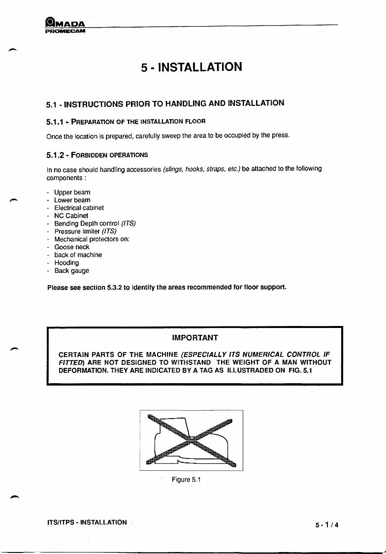
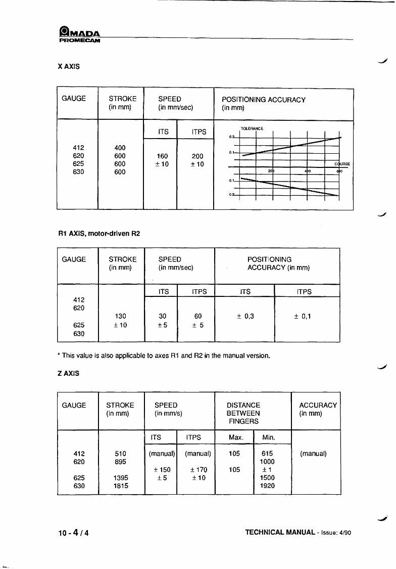
X AXIS
GAUGE STROKE SPEED POSITIONING ACCURACY (in mm) (in mmJsec) (in mm)
ITS ITPS TOLERANCE
o.!)- -----412 400 ----.---0.1 620 600 160 200 ---625 600 ±10 ±10 C(~RSE
630 600 20 40 6 0
0.1 1--. -r---_ -r---0." ~
R1 AXIS, motor-driven R2
GAUGE STROKE SPEED POSITIONING (in mm) (in mm/sec) ACCURACY (in mm)
ITS ITPS ITS ITPS 412 620
130 30 60 ± 0,3 ± 0,1 625 ±10 ±5 ± 5 630
*' This value is also applicable to axes R1 and R2 in the manual version.
ZAXIS
GAUGE STROKE SPEED DISTANCE ACCURACY (in mm) (in mm/s) BETWEEN (in mm)
FINGERS
ITS ITPS Max. Min.
412 510 (manual) (manual) 105 615 (manual) 620 895 1000
± 150 ± 170 105 ±1 625 1395 ±5 ±10 1500 630 1815 1920
10 - 4/4 TECHNICAL MANUAL - Issue: 4/90

PROMECAM
11 - LOCATION OF CONTROL DEVICES
11 - 1 ON THE ELECTRICAL CABINET
A E
o
H
J --t--
K --+-~
1-1--- B
(f) I-W---f.-- G
D'-----+-- F 1--___ -1-----_0
I--t--- L 1----1---- M
1----+--- N
1----+ __ C
I: Plotting stop control A: Machine identification tag B: Bending chart J: Coining selection (Hydraulic back gauge C: Approval plate D: Master switch E: ON indicator light F: Motor start-up control G: Green motor start-up indicator light H: Cycle selection
I.T.S· LOCATION OF CONTROL DEVICES
time delay deletion) K : Control with or without numerical control l: Automatic pressure holding control M : Hour meter N: Fan o : Radius bending selection
11 -1/12
--------------------------------------------------------------------------------------------------------~

PROMECAM
11 - 2 START-UP
- Turn master switch (D); the white indicator light (E) lights up. - Turn motor starting key (F); the green indicator light (G) lights up.
If the machine has numerical control:
- Put switch (K) on numerical control position. - The numerical control lights up and makes a sound modulation. - The numerical control is then ready to bH reset.
11 - 3 DESCRIPTION OF CYCLES
THE OPENING PEDAL OVERRIDES IN ALL CASES.
Above the mute level, the opening pedal must be held down in order to open.
Below the mute level, the opening pedal must be released. In this case, the press is open to B.D.C. as set. J'
CYCLE 1 : adjustment
- Means of control: pedal - Cycle selector (H) on position 1 - On all travel: working (operating) speed - Stoppage at mute level if the selection was made on selector (I)
~"'4 2.c~
3
.--STOP <,,""" CYCLE 2:
- Means of control: pedal - Cycle selector (H) on position 2
BREAKDOWN OF CYCLE
- Closure at approach speed up to mute level. - Mayor may not stop at sequence level (selection made by switch (I)). - Closure at working speed. - Automatic pressure holding or pressure holding by pedal, according to selection made on
selector (L). - Automatic decompression.' - Opening at high-speed down B.D.C. as set.
RELEASE OF THE PEDAL DURING THE CLOSURE PHASE CAUSES THE BEAM TO STOP IN WHATEVER POSITION IT IS FOUND.
11-2/12 TECHNICAL MANUAL - Issue: 4/90

lIMADA PROMECAM
CYCLE 3:
- Means of control two-hand control + pedal. - Cycle selector (H) on position 3.
BREAKDOWN OF CYCLE
- Closure at approach speed up to mute level, by means of two-hand control panel Mandatory stoppage at sequence level
- Release of two-hand control - Closure at working speed above mute level, by means of pedal - Automatic pressure holding or pressure holding by means of pedal, according to selection made
on (L) - Automatic decompression - Opening at high-speed up to B.D.C. as set.
RELEASE OF THE CONTROL MEANS DURING THE CLOSING PHASE CAUSES THE BEAM TO STOP IN WHATEVER POSITION IT IS FOUND.
CYCLE 4 :
- Me"ans of control: two-hand control panel - Cycle selector (H) on position 4.
BREAKDOWN OF CYCLE
- This cycle is exactly like cycle 2; the only difference is in the selection of the means of control.
I.T.S - LOCATION OF CONTROL DEVICES 11-3/12

tlMADA PROMECAM
11 - 4 ON NC CONTROL PANEL (OPTION)
Function keys:
- KEY:
- KEY:
- KEY:
- KEY:
- KEY:
- KEY:
- KEY:
- KEY:
- KEY:
- KEY:
- KEY:
-KEY:
11-4/12
-~
___ I AUX I
Programming of axes, items 1, 2 and 3 (white)
REAR GAUGE BLOCK, item 1 (white)
c:J --- TOOL PENETRATION (2) (white)
AUXILIARY AXIS, item 3 (white)
G --- REAR GAUGE BLOCK WITHDRAWAL TIME DE~AY (4)(white)
---~ ------ AUXILIARY FUNCTION PROGRAMMING ~ (5) (blue)
EJ --- FAST MOVEMENT OF AXES IN MANUAL MODE (6) (blue)
---8 D FORWARD, REVERSE, UP, DOWN CONTROL IN LOW-SPEED MANUAL MODE (7 and 8) (blue)
-0 PROGRAM CALL (9) (yellow)
----- 0 ---- PROGRAM STEP CALL (10) (yellow)
-rn ----- ACCESS TO AXIS SETTING AND CALIBRATION VALUE PLUS EMERGENCY STOPPAGE (11) (red)
DIRECT STORAGE OF CURRENT ,----- POSITION OF AXES IN MEMORY
(setting) (12) (yellow)
D. ACCESS TO INCH OR MM CONVER----- ----- SION (this operation lights up the corres-
ponding LED) (27 and 13) (yellow)
TECHNICAL MANUAL - Issue: 4/90

PAOMECAM
- KEY:
- KEY:
- KEY:
- KEY:
- KEY:
- KEY:
- KEY:
- KEY:
NUMBER FOR RECALLING A PROGRAM STORED IN EXTERNAL MEMORY (14) (yellow)
TRANSFER FROM NUMERICAL CONTROL MEMORY TO EXTERNAL MEMORY (16) (yellow)
TRANSFER FROM EXTERNAL MEMORY TO NUMERICAL CONTROL MEMORY (yellow)
DATA CANCELLATION (25)
CORRECTION OF DATA ON X AND Y AXES (26)
CORRECTION OF DATA ON X AND Y AXES (26)
WRITE OF DIMENSIONS, WITH DECIMALS, ON X AND Y AXES (comma decimal function) (26)
STARTS ACTIVITY EXECUTION (resetting, program start) (31)
- KEY: ~-- OPERATION IN AUTOMATIC MODE (28)
- KEY:
- KEY:
NOTE:
r:-l If t:..:....r -'
20
L[!l 21
~ _eo':X
9 10 11 12 13 14 IS 16
DATA READ AND PROGRAMMING and program recall (29) (WRITE MODE)
MANUAL CONTROL OF MOVEMENT AXES (30)
24
I AUTbMAI
25
~00~ 8G~~ 0000 EJ I 0 I I I
T 26
27 {g L n rnm
Use of certain keys is associated with the intervention of a sound warning which indicates that a cycle is being executed, that an operation has been completed, or that an operation is being carried out under abnormal conditions.
I.T.S - LOCATION OF CONTROL DEVICES 11-5/12

'-IMADA PROMECAM
11-6/12 TECHNICAL MANUAL - Issue: 4/90
-----

PROMECAM
11.5 - USE OF THE LIGHT GUARD
UK safety standards
- Guard only - Single break - Double break
ELEMENT FOR SELECTION OF THE CYCLE AND CONTROL MODE
- GUARD CONDITION INDICATOR LIGHTS
- GUARD CONTROL BOX
- CYCLE SELECTOR
single
break
u
Guar only
I Guard reset I
(Locate on numerical contraiL panel - ITPS)
1. Manual (slow speed) 2. Normal 3. Single/double break 4. 2 hand operation (not used in the UK)
ITS· LOCATION OF CONTROL DEVICES
Double
break
___ -- Pushbutton with
indicator light, item
~i 1
_4~2~ti 3
...... STOPo'l
11·7/12

PROMECAM
11.5.1 GUARD MODE ONLY
The guard has a safety function only
The control box selector is set to "guard only'"
The cycle selector is set to "1" or "2"
1st example
I
-"S,'-/ I "
G
GUARD
A R
CONTROL BOX CYCLE SELECTOR
~t 1
[Guard reset I _'~2~tt 3
___ STOP "..'t
EVERYTHING OK - The bending cycle can start
2nd example
GUARD CONTROL BOX CYCLE SELECTOR
0 ~j 1'6- 2 1
-.~~t1 -'~-
L.9uard reset I S S -~&- 3
/ I "
~STOP~ / I '
G A R
OR
REQUIRES RESET
The cycle can only start after guard reset
G A R
11 - 8/12 TECHNICAL MANUAL - ad: 04/90

PROMECAM
RESET PROCEDURE
- Press pushbutton "GUARD RESET"
- Interrupt the guard once or twice.
a) "Guard Reset" remains on:
- The beam has not reached the bottom dead point
Fully press the "opening" pedal to teach the bottom dead point.
- Press GUARD RESET - The indicator light comes off. The green indicator light of the guard is on
The bending cycle can start.
CYCLE SEQUENCING
Press the "closing" pedal
2 situations may occur:
a) There is no interruption of guard during the approach phase:
The press brake closes down to the mute level. Once this level is reached, the amber indicator light
of the guard comes on, and the green indicator goes off.
From that moment the light guard is inoperative, (since the press brake is in the safety area), and the
"GUARD OFF" warning light will come on.
The bending sequence can then take place. After bending the press brake is brought down to the
bottom dead point.
Once the press brake has reached the bottom dead point, everything is O.K. and the next cycle can
start: Interrupt the guard once, the machine is then reset (green light is on).
b) If the guard is interrupted during the approach stroke: the cycle is stopped, the ram falls away
and a reset of the guard is necessary, (see guard rese~.
I.T.S - LOCATION OF CONTROL DEVICES 11-9/12

PROMECAM
11.5.2. - "SINGLE BREAK" MODE
(The guard has a safety function and a control function)
Switch the control to selector to position: "SINGLE BREAK"
Switch the cycle selector to position: CYCLE 3
1st example
GUARD CONTROL BOX CYCLE SELECTOR
0 ~t 1 2 1
-O~ _'~2~tt I Guard reset I ~
~ 3
.--STOP ",..'"
G A. R
EVERYTHING OK - The bending cycle can start
2nd example
GUARD
._'~/-/ I '
G A R
CONTROL BOX
o 1'6,2 I Guard reset I
-'~-" I '
CYCLE SELECTOR
~i ,
_'~2~tt 3
~STOPc'"
RESET - The cycle can start only after reset
In this case proceed in the same way as described in paragraph "GUARD ONLY" i.e., by positioning the press brake at the bottom dead point.
11-10/12 TECHNICAL MANUAL - ed : 04/90

ilMADA PROMECAM
CYCLE SEQUENCE
Interrupt the guard once. The green indicator light comes on. The press brake closes fast and stops at the mute level.
a) During this phase, if the guard is interrupted, the closing stroke stops and the ram falls away. A reset is necessary, (see reset).
b) If there is no interruption of the guard during the approach stroke, the cycle is completed by pressing the "closing" pedal above the mute point.
Once the press brake has reached the bottom dead pOint, everything is OK and the next cycle can start: interrupt the guard once.
11.5.3. DOUBLE BREAK MODE
(The guard has a safety function and a control function)
- Switch the Control box selector to position 2: "DOUBLE BREAK"
- Switch the Cycle selector to position 3: CYCLE 3
GUARD CONTROL BOX CYCLE SELECTOR
0 ~i 1 2 '0 1
_'~2~it I Guard reset I ~
~ 3
~STOP <"'t G A R
EVERYTHING OK - The bending cycle can start
1st example
GUARD CONTROL BOX CYCLE SELECTOR
o
1'0 2
I Guard reset I -'~/-
/ I '
~i 1
_4~2~ti 3
___ STOP.,.,..'" G A R
RESET - The cycle can start only after reset
2nd example \0 this case proceed as described in paragraph "GUARD ONLY" i.e., by positioning the press brake at the bottom dead point.
I.T.S - LOCATION OF CONTROL DEVICES 11 - 11 112

PROMECAM
CYCLE SEQUENCE
Same operation as in "SINGLE BREAK" mode except that the guard has to be interrupted twice before initiation of the press brake.
WARNING
During the first cycle, one SINGLE guard intE~rruption initiates the machine cyle.
11. 5.4 - IMPORTANT
1) In the "SINGLE BREAK" and "DOUBLE BREAK" cycles, once the cycle is completed if no other operation is performed and after 30 seconds", the "GUARD RESET" push button comes on.
The selector switch must be positioned back to "GUARD ONLY"; press "GUARD RESET", set the selector to the required cycle 1 or 2, and interrupt the guard once.
* The timing relay KA 21 inside the electrical panel is set to 30 seconds, which is assumed to be the -' normal component cycle time. This should be adjusted for greater or lesser cycle times so that if the machine is not initiated within this period, thE! controls will revert back to normal means of initiation.
This is a safety feature and should be adjlUsted by a competent person.
2) The mute position ("GUARD OFF'" should be set at a point just above the material thickness which is being processed. Under no circumstances can it be set at more than 6mm above material thickness.
3) The distance bars fixed to the front of the machine are to prevent any person walking through the light curtain and Auto initiation occurring. They should be maintained in their present condition and should not be removed under any circumstances.
11-12/12 TECHNICAL MANUAL - ad : 04/90

ClMADA PAOMECAM
12 - MB NUMERICAL CONTROL (OPTION)
12 - 1 DESCRIPTION
The M B numerical control is a very simple option, ideal for increasing the productivity of a Promecam AMADA press brake.
The MB numerical control manages 1, 2 or 3 axes (X, V, R or Z). There are 4 different versions.
A self-diagnostic program, linked to the appearance of numbered error messages, facilitates usage and maintenance of the numerical control.
12 - 2 GENERAL CHARACTERISTICS OF THE MB NUMERICAL CONTROL
- The numerical control unit accepts up to 81 program steps. - 380/220 V supply voltage, three-phase, 50160 Hz current. - Power consumed, according to case of usage, either 300 or 500 W. - Display of 1 to 30 program steps. - Alphanumeric display. - Values shown on display. - Memory capacity: 9 programs. The number of bends stored in memory can include up to 81 steps. - Operating mode: manual or automatic. - Programming mode. - Data recording format: X axis: 999.9 mm; Y axis: 99.99 mm; AUX axis: 999.9 mm - Automatic conversion of data stored in inches or millimeters. - Visual and sound signal in case of operating errors. - Automatic recalibration. - Programming of up to 8 machine functions. - Backup of programs in external memory. - Unlimited duration of memories. - Incremental positions sensors.
I. T.S • MB NUMERICAL CONTROL (OPTION) 12-1/6
tlMADA PROMECAM
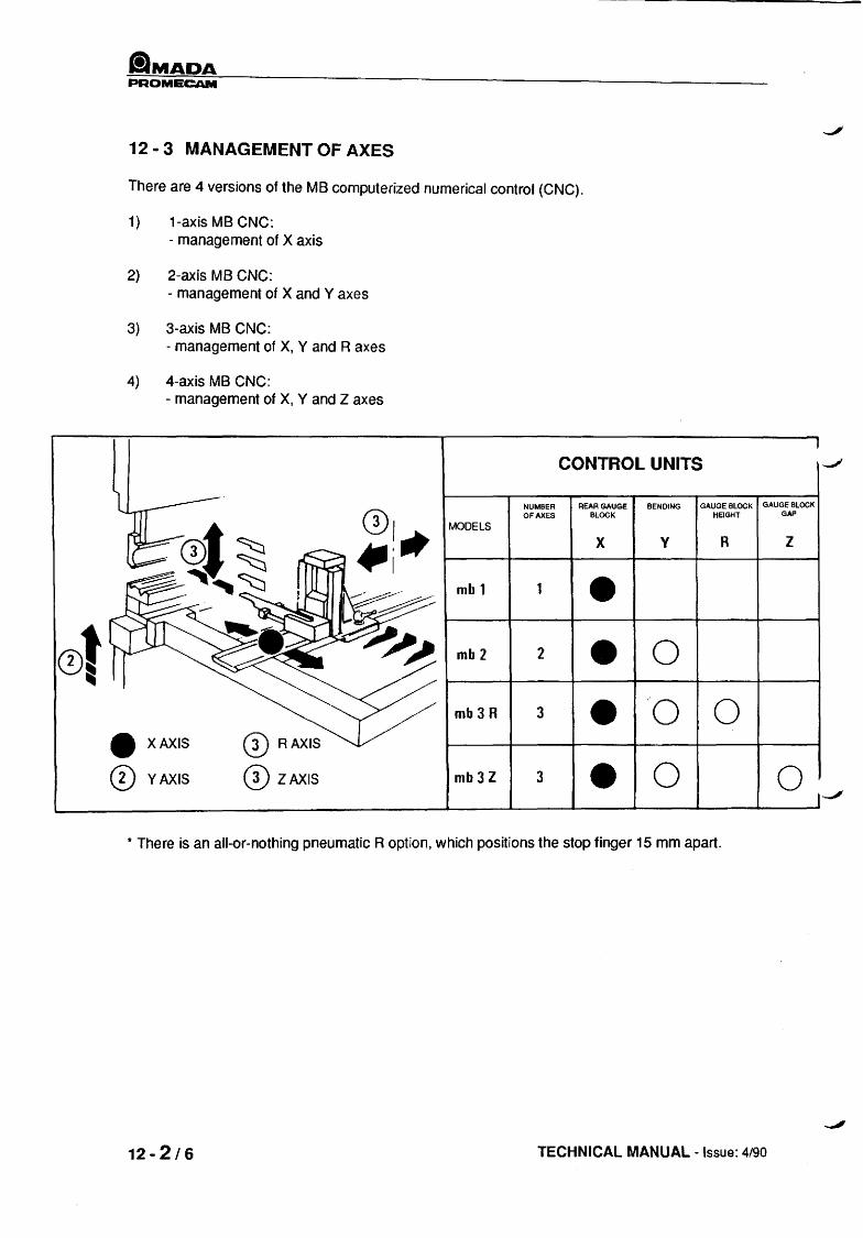
12 - 3 MANAGEMENT OF AXES
There are 4 versions of the MB computerized numerical control (CNC).
1) 1-axis MB CNC: - management of X axis
2) 2-axis MB eNC: - management of X and Y axes
3) 3-axis MB CNC: - management of X, Y and R axes
4) 4-axis MB CNC: - management of X, Y and Z axes
CONTROL UNITS
NUMBER REAR GAUGE BENDING GAUGE BLOCK GAUGE BLOCK
01 OF AXES BLOCK HEIGHT GAP
MODELS
4IIi'" X V R Z
mbl • 0t mb2 2 • 0
IIIi
mb3R 3 • "0 0
• X AXIS CD RAXIS
CD YAXIS CD lAXIS mb3Z 3 • 0 0 --'
* There is an all-or-nothing pneumatic R option, which positions the stop finger 15 mm apart.
12 - 2/6 TECHNICAL MANUAL - Issue: 4/90

PROMECAM
12 - 4 OPERATING DIAGRAM
Control panel
Power control plate
Encoder
Encoder
Start cycle switch on depth control, referred to as "hydraulic gauge block"
380 or 220 V power supply
"'""
/ [: w
PANEL ~ V .-J a.. CONTROL
.-J
/ 0 a: ~
~ z T encoder ---MF::.AV.AR.R. 0 ()
enaJder V~@BF a: w
-fi-@E): ~ . ___ F.C.AV+AR+Rm+RQ 0-F k
-----!\9 ___ F.C-x.JL:J
.. .. -----e)3
I.T.S - MB NUMERICAL CONTROL (OPTION)
... ......
~ ...
START CYCLE CYCLE
220 ou 380 POWER SUPPLY
12-3/6
ilMADA PROMECAM
12 - 5 CHARACTERISTICS OF COMMAND AND CONTROL PANEL BOARDS
The logic unit consists of six boards, the functions of which are listed below.
12 - 5 - 1 E5 POWER SUPPLY BOARD (AL3)
Receives the power supplies coming from the "AU" (emergency stop) power supply board. These power supplies are filtered and stabilized on this board in order to obtain constant voltages for operation of the entire positioning assembly.
Stabilized voltages:
+5V
+ 12V - 12V
- 30V - 12V
- power supply of integrated circuits
- power supply of circuits with special technical characteristics requiring these voltages for their operation
- supply voltages for ER 3400 memories.
12 - 5 - 2 E4 MOTOR BOARDS (MOT)
The E4 motor board has three independent circuits whose function is to control the speed and direction of each motor.
12 - 5 - 3 E3 MICROPROCESSOR BOARD (Mu)
The E3 microprocessor board controls all the functions of the equipment. These functions are microprocessor-controlled by means of a software program stored in the memories of this board. The microprocessor board can interact with a group of logic circuits through the input and output buses.
12 - 5 - 4 E2 INTERMEDIATE BOARD (INT)
A series of integrated circuits are IDeated on the intermediate board; these circuits receive the square wave signals, phase shifted among themselves by 90°, produced by the incremental sensors (X-Y axes), and transformed on output into pulses that are counted by the microprocessor.
In addition, other types of integrated circuits receive instructions from the microprocessor; they are decoded to select the ER 3400 memories, which contain all the data from the work program. A system of integrated circuits decodes signals for machine functions; other logic circuits transmit the motor speed command to the motor board.
12 - 4 /6 TECHNICAL MANUAL - Issue: 4/90

flMADA PROMECAM
12 - 5 - 5 E1 FRONT PANEL BOARD
The front panel of the command and control unit consists of:
- a keyboard numbered from 0 to 9 for entering data. - operating push-buttons for selecting the type of machine operation. - a group of function keys to store data and other special instructions. - digital and alpha-numeric displays used to display the data entered and to execute other
operations. - a locking socket, onto which is mounted the removable memory for transfer of data. - a sound signal.
12 - 5 - 6 E6 BASIC BOARD
All the boards above are attached by means of connectors to the basic board, which connects them to each other.
CONTROL BOARD CHARACTERISTICS (power cabinet)
The boards listed below are control boards.
12 - 5 - 7 E8 SETTING BOARD (CMT)
The E8 setting board includes control circuits with double-thyrister triggers (SCR) and an analog stabilization circuit for the current loop.
12 - 5 - 8 E10 CONSTANT-CURRENT REGULATOR BOARD
The E10 constant-current regulator board has a control circuit with thyristors (SC) and a current loop detector.
12 - 5 - 9 E9 REGULATOR BOARD (APP3)
12 - 5 - 1 0 E7 POWER SUPPLY BOARD (AU)
The E7 power supply board has a hexa-phase Graetz bridge, a +9 V stabilized circuit and integrated circuits for stabilization at + 12 V.
I.T.S - MB NUMERICAL CONTROL (OPTION) 12-5/6

PROMECAM
12 - 6/6 TECHNICAL MANUAL - Issue: 4/90

t!lMADA PROMECAM
13 - BENDING TECHNIQUES
There are two basic bending techniques:
- Air bending
Usually used because it requires relatively low forces.
- Coining: Requires forces equal to 4 or 5 times that of air bending; nevertheless makes it possible to obtain a remarkable angular accuracy by die stamping the inside radius, which cancels the elasticity of the metal.
13·1 AIR BENDING
During bending, the worksheet maintains part of its elasticity. It is therefore necessary to execute a more closed angle than the angle required, in order to compensate for the opening due to this phenomenon. The computer integrates all the parameters required for air bending. Our standard air bending tools are designed in light of this. The bending chart on the electric cabinet of the press shows the forces required and the inside radii obtained as a function of the other characteristics (thickness and quality of worksheet, die opening, etc.).
a) Partial air bending: The deformation of the worksheet is interrupted before the worksheet is brought to the penetration limit in the die. The worksheet is in contact with the tools at three points, A, Band C, as shown in the figure below. The practical result of this special feature is that it maintains the quality of the bending: Die = 8 to 10 times th (for angles ~ 135°, it is preferable to use die = 10 to 12 times th).
V=12x( V=6-12xr
NOTE:
If a special angle is required,tools can be made at the bending angle, which brIngs us to the technique referred to as "air bending in die bottom".
b) Air bending In die bottom: to make 90° bends. In this case, the worksheet goes down to the bottom of the die and rests against its sides. This leads to an increase in the force required.
NOTE:
This type of bending generally applies to worksheets greater than 2 mm thick.
I.T.S· BENDING TECHNIQUES 13 ·1/8

~MADA PROMECAM
13 - 2 COINING
This type of bending is comparable to stamping. The punch tip, when at the bottom of the die, breaks the elasticity of the worksheet, which then takes on the exact form of the punch.
In practice:
- NOTE:
for 90° bends width of die: 5 to 6 times thickness angle die: 90° angle punch: 90°
Very strong forces must be used. These may go as high as 4 to 5 times the forces shown on the air bending chart. This type of bending generally applies to worksheets up to 2 mm thick.
punch blade
V=5-6xt -J
EXAMPLE OF TOOLING SELECTION
a} For $ 90° bending
thin metal sheet (400 N/mm2) 1.5 mm thick 12160° die 60° punch, 0.8 mm radius
b) For ~ 90° bending
13 - 2/8
150°, for example thin metal sheet (400 N/mm2) 1 mm thick 12160° die 60° punch, 0.8 mm radius
TECHNICAL MANUAL - Issue: 4/90

liMADA PROMECAM
13 - 3 PUNCHING TECHNIQUE
The gooseneck or special assemblies on the machine can be used to carry out punching, notching, etc. operations. Nevertheless, certain rules should be observed in order to avoid accidents involving the press and so that operations can be carried out correctly.
The force used for punching must be limited to the values listed in the chart below.
We recommend that you symmetrically step punches on the axis of the press. By placing the units at several different levels, the punching capacity will be multiplied by the number of levels. The instantaneous force should in no case exceed the values listed in the chart.
Insofar as possible, punch grinding should be progressive.
FOR ALL PROBLEMS CONCERNING PUNCHING AND BENDING, WE RECOMMEND THAT YOU CALL THE TECHNICIANS IN OUR SALES ENGINEERING DEPARTMENT.
The values in the chart are understood to be for punches symmetrically distributed in relation to the axis of the beams.
0/0 FORCE
'" 50
40
30 / ./ /'
/ " 20
10
..... ~ w
1 ORKSHEET
2 3 4 5 6
I.T.S - BENDING TECHNIQUES 13 - 3/8
6

tiMADA PROMECAM
13 - 4 MOUNTING TOOLS
We strongly recommend that the order of assembly be kept to, for reasons of facility and safety.
1) Die or vee (V) 2) Punch or counter-vee (CV)
13 - 4 - 1 MOUNTING DIES
The dies are slid on the resting plane of the lower beam and locked home in place by the front plates. The rear plates are the vertical reference surface and must never be unlocked.
flat reference bracket
13 - 4 J 8
lightening bracket
For dies with two vees, loosen their lock screws before making the punches.
(115)
26
34 (115) 75
55
13 - 4 - 2 ASSEMBLY OF FLLER BLOCK
(101)
Caution: When assembling a feeder bush, make sure that the flat brackets (slick brackets section) are at the back of the resting plane of the lower beam. These brackets must in no case be unlocked.
TECHNICAL MANUAL - Issue: 4/90
~'

flMADA PROMECAM
13 - 4 - 3 ASSEMBLY OF PUNCHES (PUNCHES WITHOUT SAFETY GROOVES)
- Set cycle selector on position 1. - Press closing pedal. - Hold down closing pedal to adjust stoppage level of lower beam (sequence or mute) using the
hydraulic gauge control (vernier wheel or knob, depending on machine type. See section 9.3). - The stoppage level must correspond to the height dimension of the punch-die assembly.
- Keeping the closing pedal pushed down, unlock the low gauge assembly by half a turn, then tighten IT back. .
~~ __ "~E \.!LOCKING
- Release closing pedal. - Press down opening pedal. This action makes the lower beam go down by a few millimeters.
The clearance thus obtained makes it possible to slide in the punches, which then lie in die bottom.
- Slightly screw in the force limiter control (pressure regulator) until the moving beam rises. - Completely disengage bending depth control (clockwise direction), to tool contact. - Turn two more times. - Tighten force limiter control (clockwise direction) until required force is obtained on pressure
gauge (black scale).
CAUTION
The maximum permissible force depends on the type of tool used; refer to the tool list.
I.T.S - BENDING TECHNIQUES 13-5/8

PROMECAM
13 - 4 - 5 DISMOUNTING TOOLS
Tools must be assembled in the following order:
a) Dismounting of punches b) Dismounting of dies
- Set cycle selector to position 1.
- Press down closing pedal. Without relElasing pedal, use the hydraulic gauge assembly control to adjust level of lower beam, so that punch and dies are in contact, then loosen and tighten the low gauge block control.
- Press down opening pedal. The clearance obtained between the tools makes it possible to slide in the punches through one of the ends of the beam.
1< STORAGE OF TOOLS:
- To protect the working edges of your tools, we advise that you store them in a special box near J the press and set them on wooden slats or soft materials.
- In case of dismounting adjustable intermediate sets for special reasons, replace these parts in order and in their respective locations.
- Dismount dies.
13 - 4 - 6 TOOL ADJUSTMENT
~l
13 - 6/8
After turning on your press:
- Set press on cycle 1 (H switch)
- Set plot stoppage (I) switch to 1.
- Press down closing pedal. The lower beam rises to the sequence level initially set.
Cht~ck distance between punch tip and worksheet.
Actuate opening pedal to bring down beam.
Set adjusting cam so that there is a maximum of 6 mm between the punch and the worksheet (Fig. 1).
Bringing the cam back up brings about a higher sequence level.
TECHNICAL MANUAL - Issue: 4190
-,'

.MADA PAOMECAM
13 - 4 - 7 LIST OF STANDARD PROMECAM AMADA TOOLS a
DIES
V aO R H L 2vees
6 90 0.4 26 6 X 10 90 0.6 10
8 90 0.5 26 8 X 12 90 0.8 10
8 60 0.8 26 8 X 12 60 1.2 10
12 88 2.75 26 10 X 20 88 3 15
16 60 1.6 26 12 X 20 60 2 15
16 88 2.75 26 12 X 25 88 3 16.5
6* 35 1 -90- 10 32 85 4 60 30 40 85 4 60 30
50 85 4 60 30 63 85 6 75 40
80 85 6 80 47.5
100 80 7 95 57.5
125 80 15 103 77
1 vee
X X X X X X
X X
The height of the die-punch assembly can be corrected in relation to the filler block selected. See section 7.3.1 for the various assemblies.
*Crushing tools.
I.T.S - BENDING TECHNIQUES 13 - 7 18

tlMADA PROMECAM
PUNCHES
H
CASE H n° R A 1 2
X 66.65 ~u 0.5 0.8 X 89.65 90 0.5 0.8 X 104.65 90 0.5 0.8 X 65.5 88 0.5 2.9 X 88.5 88 0.5 2.9 X 103.5 88 0.5 2.9 X 65.2 45 0.5 1.5
X 67 60 0.8 X 65.8 60 2
X 85 35 0.1 0.8 X 65 60 6
13 - 8/8 TECHNICAL MANUAL - Issue: 4190

PROMECAM
14 - USE WITHOUT NUMERICAL CONTROL
14 - 1 PRELIMINARY OPERATIONS
Before carrying out any bending operations, it is necessary to define:
The bending technique:
- air bending or
- coining (see section 13)
14 - 2 IMPORTANT RECOMMENDATIONS
In order to avoid any accident during bending operations, it is imperative that the instructions below be followed:
a. Never run the pump when there is no oil in the tank.
b. Never use the pressure regulator on the bending depth setting.
C. Do not exceed the maximum permissible force for tools.
d. After usage, completely loosen the pressure regulator and the hydraulic gauge control.
14 - 3 TURNING ON AND OFF
See section 11.2.
14 - 4 MUTE LEVEL SETTING (SEE SECTION 13.4.6)
I.T.S - USE WITHOUT NUMERICAL CONTROL 14 - 1/4

tlMADA PROMECAM
14 - 5 PRESSURE REGULATOR SETTING
The regulator control makes it possible to set the required force.
This operation is carried out by actuating the regulator control.
The force is checked on the pressure gauge.
The pressure gauge has two graduated scales, continuously giving the following information:
The force in tonnes, given by the small side of the needle, on the black scale,
The minimum bending length in order to not damage the tool, given by the large side of the needle, on the red scale.
CAUTION
NEVER USE THIS CONTROL TO SET THE AIR BENDING DEPTH (NO ACCURACY SETTING FOR END-OF-BENDING DIIVIENSION)
Adjusting Force as a Function of Bending Length
This setting consists in limiting the force of the press in relation to the permissible unit load of 1.2 tons per centimetre of bending length.
This setting must be made before carrying out any bending operation (no matter what technique is used), with a view to preventing any deterioration of bending tools or of their supporting forces.
14 - 2/4 INSTALLATION MANUAL - Issue: 4190

ilMADA PROMECAM
- Completely loosen the pressure regulator control; put into contact with tool (die bottom); use pressure gauge to check that the pressure is not rising.
- Tighten regulator control to the force required for bending (clockwise direction).
- Press pedal and turn hydraulic gauge control in clockwise direction until the tools come into contact.
When using vees larger than 40 mm, insert a worksheet between the tools {to protect tool}.
- Tighten pressure regulator control (in clockwise direction) until the length corresponding to the part to be bent is displayed on the red scale of the pressure gauge.
The bending force is therefore limited to the condition of 1.2 tlcm.
NOTE:
- For short bending lengths, the pressure regulator must be set below 20%, of the nominal force of the press brake.
- Likely to make approach and working speeds drop.
- When the setting has been made, the pressure regulator must not be used during bending operations. except to compensate for the spring back of the material when setting the bending angle.
14 - 6 HYDRAULIC GAUGE BLOCK CONTROL SETIING •
This control is used to set the bending depth (or penetration height of the punch into the die), by stopping the moving beam from rising at the selected point of stoppage.
This stoppage point is set by turning the moving vernier.
This is accurate to a few hundredths of a millimeter. even during bending.
To increase the height of the stoppage point, tum the vernier in the clockwise direction.
To decrease this height, turn the vernier in the counter-clockwise direction (see section 9.3).
I.T.S - USE WITHOUT NUMERICAL CONTROL 14 - 3/4

PROMECAM
After making the final setting, tighten the locking screw to lock the assembly in place.
NOTE 1: If too closed of a bend is obtained during settings, release the control pedal and turn the hydraulic gauge block control In the clockwise direction.
NOTE 2: In the case of blow bending, if the bend is too closed, turn the hydraulic gauge assembly control in the clockwise direction. In this case a bend that Is more closed than the angle of the tool Indicates that the force is too low.
NOTE 3: If there are several variations in angles over the entire length of the bend, check that the tools (the die and the punch) are in good condition. Adjust the Intermediate sets.
14 - 4/4 INSTALLATION MANUAL - Issue: 4/90

ilMADA PROMECAM
15 - USE OF NUMERICAL CONTROL (TYPE MB)
15 - 1 PRELIMINARY OPERATIONS
- Start-up: refer to section 11.2.
- The type of numerical control and the date of the software program are displayed for a few seconds (24). This display is followed by another, indicating the number of startups.
- The flashing entry START appears on the alphanumeric display device (item 31).
- One of the indicator lights up (inches or millimeters).
- Various segments appear on the displays (17 and 18).
- After this first operating phase, which takes place in a very brief time, the microprocessor is ready to carry out a first origin setting operation (X, V, R or Z).
- Press the flashing START key I START I (31) to start the origin setting.
- When resetting is completed (beep), go into write mode by pressing the I'~ I key (29).
Display the adjustment values; hold down the [E] key (11) for more than 2 seconds.
- The adjustment values are then displayed and can be modified. Check that they indeed correspond to the values shown on the inspection sheet that comes with your machine.
- Follow the procedure in section 15.4 to change the resetting values.
tT.S - USE OF NUMERICAL CONTROL (TYPE MB) 15 - 1 114

&MADA PROMECAM
15 - 2 OPERATION
15 - 2 - 1 MANUAL MODE
- Press the D key (30) to go into manual mode.
roAI - Select the mm or inch unit by holding down w.J (13) for 2 seconds.
- By pressing the D D a (1, 2 or 3) keys, the alphanumeric display (24)
shows the entry MANUAL X, MANUAL Y or A = nn.n.
a) MANUAL X:
- Pressing the Q key (7) makes the X axis move away from the bending axis.
- Pressing the D key (8) makes the X axis move closer to the bending axis.
b) MANUAL Y:
- Pressing the Q key (7) makes the distance between the punches and dies increase
(pedal up, engaged).
- Pressing the D key (8) makes the distance between the punches and dies decrease
(pedal up, engaged).
A short impulse on (7) or (8) results in a movement of 0.01 mm.
NOTE:
Simultaneous pressing of (7) or (8) and (6) results in high-speed rotation of the motor of the axes In question (X or V).
15-2/14 TECHNICAL MANUAL - Issue: 4/90

.MADA PROMECAM
c) A = nn.n
- Pressing the 8 key (7) makes the rear gauge stop lingers rise or separate (as
per R or Z configuration of gauge assembly).
- Pressing the D key (8) makes the rear gauge stop lingers descend or come
closer to each other.
When the values X, V, R or Z have been reached in accordance with the procedure below, the operator can carry out the bending operation.
I.T.S- USE OF NUMERICAL CONTROL (TYPE MB) 15 - 3/14

ilMADA PROMECAM
15 - 2 - 2 PROGRAMMING
- Go into programming mode by pressing I·€> I (29). All the display windows are empty,
except for 19 (bend number) and 20 (program number set to 1).
- The indicator lights (27) light up in accordance with the last selection made (inches or millimeters) .
- Select the program number (from 1 to 9) then press key c::::J (9).
The amount of available memory is displayed (maximum of 81 steps). The program number selected is displayed on (20). The number of the first non-programmed bend ;s displayed on (19).
1 - ENTERING X-AXIS VALUE
- Enter the dimension on the numeric key-pad (26).
- Press 0 key (1); the value appears on the display (18).
2 - ENTERING V-AXIS VALUE
- Enter the dimension on the numeric key-pad (26).
- Press c=:J key (2); the value appears on the display (17).
- A sound signal indicates and confirms that it has been stored in memory.
3 - ENTERING AUX-AXIS VALUE
- Enter the dimension on the numeric key-pad (26).
- Press 6 key (3); the value appears on the display (24).
4 - RELEASE OF PART
_ Between two successive bends, it may prove necessary to provide a withdrawal on the X axis, or simply a waiting time for this axis, before positioning a new part. -,,'
_ After a bend has been made, the rear gauge assembly is locked for a time that can be
programmed from 0 to 9 seconds.
- Program this time on numeric key-pad (26).
- Press ~ key (4).
- The withdrawal time is then entered in memory. _ Programming of a withdrawal time validates this value on the selected bend(s).
_ To cancel the withdrawal time programming, simultaneously press the
andthe ~ key (4).
o key (25)
15-4/14 TECHNICAL MANUAL - Issue: 4/90

,"'"
aMADA PROMECAM
5 - CHANGING THE REAR GAUGE BLOCK WITHDRAWAL VALUE (IN PROGRAMMING MODE)
- Use the [IJ key (11) to call up the calibration values.
- Hold down (4) for two seconds to read the withdrawal values.
- Enter the selected dimension on the numeric key-pad (26) (0 to 600) and press G (4).
For example:
- Gauge assembly value (X) ;;; 100 - Required withdrawal = 50 - Enter 50 on the key-pad (26) _ The maximum withdrawal value must not exceed the capacity of the gauge assembly, i.e.
600 mm.
- Press the G key (4) to validate,
- The gauge assembly moves back to 150 mm, awaits the program time "t" before positioning itself for the next bend.
6 - MACHINE FUNCTION
- Key ~ (5) is used to confirm an external all or nothing function (for example, a solenoid).
- This function can be associated to making the selected bend, within a given program.
- Type the number of the function on the numeric key-pad (26) (from 1 to 6).
- Then press the ~ key (5).
To cancel a machine function, type 0 on the numeric key-pad (26) and press ~ (5),
7 - PROGRAMMING OF NEXT BEND
- Press the 0 key (10); program the bend according to the same procedure used for
bend number 1 .
I.T.S· USE OF NUMERICAL CONTROL (TYPE MB) 15-5/14

PAOMECAM
15 - 2 - 3 - RUNNING A PROGRAM
- Press the 0 key (29) to go into programming mode_ Type the number of the program
you wish to use on the key-pad (25), then press the ~ key (9).
- Press ~ (10) to display 1 in window 19.
- Press 0 (28) to go into run mode.
- The START indicator light (31) lights up. - Press START. The axes are positioned for bend number 1. - Make the bend (see cycle selection heading in section 11.3). - Each time the press starts to open, the axes are positioned for the next bend.
15 - 2 - 4 CORRECTION OF A BEND WITHIN A PROGRAM
Corrections may be made to the following parameters:
- Back position value (X). - Penetration value (Y). - Gauge assembly withdrawal value. - Gauge assembly withdrawal delay. - Machine function (auxiliary axis).
In all cases, press I'~ I (29) to go into programming mode.
1 - BACK POSITIONING OR PENETRATION VALUE
- Select the correction sign on the key-pad (26): <10 mm on X axis. - Type in the correction value on the key-pad (26): <10 mm on the Y axis.
- Type ~ (1) or ~ (2), according to the axis selected.
2 - GAUGE ASSEMBLY WITHDRAWAL DELAY
The gauge assembly withdrawal delay consists of reprogramming with new value(s), according to the procedure described in 15.2.2. Warning: Only one withdrawal value per part can be selected for n bends.
3 - MACHINE FUNCTIONS (SEE 15.2.6)
4 - DELETING A BEND
- Enter the number of the bend to be deleted on the key-pad.
- Press ~ key (10) and hold down; press the 0 key (25).
- WAIT appears on the alpha-numeric display (24). - Release the keys. - A sound signal indicates cancellation. - The numbering of the bends is automatically changed.
15-6/14 TECHNICAL MANUAL - Issue: 4190

PAOMECAM
15 - 2 - 5 DELETION Of A PROGRAM
- Enter the number of the program to be deleted on the numeric key-pad (26).
- Then press the 0 key (9), then holding it down press the 0 key (25),
- WAIT appears on the alpha-numeric display device (24).
- Release the keys.
A sound signal indicates cancellation of the program.
15 - 2 - 6 TRANSFER OF PROGRAM INTO EXTERNAL MEMORY
External memory capacity = 2 programs with a total of 45 bends. One of the programs can contain up to 30 bends.
- To transfer data from a program into an external memory, insert the external memory into the base (32).
- With the numeric control in 1-<;> 1 mode (29), retrieve the program (type in its number),
Press the 0 (9),
- Assign it a number (which is to be engraved on the housing of the memory, for example 1234).
- Then press ~ key (14),
- Press 1 or 2 on the numeric key-pad (26). according to the memory space available,
then press the 1 0-1 key (16)
- The following message appears on the alpha-numeric display device (24):
Write symbol W EXT 1 program number
- A beep indicates the end of transfer.
transfer into external memory
- Unplug the EPROMs from the memory and store them for future usage.
NOTE:
Caution : Watch out for possible program losses caused by overwriting In the external memory.
I.T.S - USE OF NUMERICAL CONTROL (TYPE MB) 15 - 7/14

PAOMECAM
15 - 2 - 7 TRANSFER OF A PROGRAM FROM EXTERNAL MEMORY INTO INTERNAL MEMORY
- Find an available programme number or make one available for a transfer into external memory, as explained in the preceding section.
- Press the 0 key (9) to make sure that there are enough bends available.
- Type 1 or 2 on key-pad (26), according to area of external memory to be transferred.
- Press the I <7-1 key (15) to make transfer .
. The following message appears on the alpha-numeric display (24):
Write symbol w
NOTE:
s
number of program selected
1234 program name
If there is a programming error (incorn~ct recording of data, entry error, omission,etc.), the word ERROR, followed by a number, appears on the alpha-numeric display device. This number is a means of Identifying the type of error (see section 15.5). COrrect the faulty parameter.
15 - 3 USE IN TEACHING MODE
- Press the key (30).
- Position the axes as described in section 15.2.1.
- When the axes are posijioned, press ~ (29).
- Press the 0 key (10) to confirm the first available bend.
- Press ! B> !(12),thensimuHaneOUSlypress0 (1)OrQJ(2)Or~ (3).
The value of X, Y or AUX will be stored in memory.
LEARNING USING MECHANICAL CONTROL WHEEL ON Y AXIS
- Press the to! key (29). At this time, the Y axis motor is in electrical'1ree wheel" mode.
- Operate handle by hand to obtain depth of bending desired.
- To store the Y axis dimension in memory, simultaneously press! B> !(12) and QJ (2).
15-8/14 TECHNICAL MANUAL - Issue: 4/90

PROMECAM
15 - 4 SELF-DIAGNOSTIC
The self-diagnostic is a software programme that checks the operating status of certain components in the MB numerical control.
15 - 4- 1 INSTRUCTIONS FOR USE
To go into diagnostic mode:
- Press any key on the key-pad (1 to 16) before powering up.
- Turn on by holding down key until end of sound signal.
- The alpha-numeric display device (24) displays the DIAGNOSTIC message.
- After a few moments, the LED TEST message appears on the alpha-numeric display (?4).
- This is the first check.
- To run the test, press the ~ key (2) (YES).
To go to the next test before the preceding one is completed, press the 0 key (10) (NO).
15 - 4 - 2 CHECKING PHASE
The following checks are made:
1 - LED Test:
LED test FM test MEN test EXT test MAN test KEY test
The LED test checks the operation of the displays by lighting up the various segments, and of the LEOs related to the control keys, items 28, 29, 30 and 31.
2 - FM Test:
- The FM test checks the operation of the machine functions on 1 to 9, through sound signals (8 or 9 are software fu netio ns).
3 - MEN Test:
- The MEN test checks the operation of the two ER 3400 memories and initializes them.
- The alpha-numeric display (24) displays the message PASSED 1 and PASSED 2 and INIZ MEM.
I.T.S· USE OF NUMERICAL CONTROL (TYPE MB) ·15:r.- 9/14 _" .:."1

&iMADA PROMECAM
4 - EXT Test:
- The EXT test checks the operation the change of steps, the ends of travel, the encoders and the X, Y and AUX axes.
- This test is carried out by lighting up the various segments on the display (17, 18, 19,20,21 and 22).
5 - MAN Test:
- The MAN test checks the operation of the motors in manual mode.
- SimuHaneously press one of the keys 0 ~ or ~ (1, 2 or 3) and the key
8 or D (7 or 8) (slow-speed).
SimuHaneously press the Bkey (6) and one of the 8 or D keys
(7 or 8) (high-speed); only the keys that define the axis must be held down when checking the -....",JJ
motors. Operation stops when they are released.
- When running the motors, the displays related to the program and to the steps display the increments per turn (19, 20 and 24).
- To continue the self-diagnostic after the end of the test, simply press the 0 key (10).
6 - KEY Test:
- The KEY test checks the operation of tile function control keys and the key-pad keys.
- When one of the keys are pressed down, the alpha-numeric display (24) displays the key required.
7 - Exit from DIAGNOSTIC mode
- At the end of the test, you can go back to the beginning of the diagnostic. It is possible to again
run the MB numeric cijltrOI, tp. dothis, simu Itaneously press 8 (7), 0 (5) and
~ (3). After the beep, t~e numeric control is operational and requests a START.
8 - Return to Beginning of DIAGNOSTIC Mode
- At the end of the KEY test, you can go back to the beginning of the DIAGNOSTIC mode by
simultaneously pressing 0 (1) 0 (5) and 0 (9).
15 -10/14 TECHNICAL MANUAL - Issue: 4190

,."....,
_MADA PROMECAM
15 - 5 ERROR MESSAGES
- ERROR 00
-ERROR10
- ERROR 11
- ERROR 12
-ERROR13
-ERROR14
- ERROR 20
- ERROR 21
- ERROR 22
- ERROR 23
- ERROR 24
- ERROR 25
- ERROR 26
- ERROR 27
- ERROR 28
- ERROR 29
- ERROR 30
- ERROR 40
- ERROR 41
- ERROR 42
_0
- ERROR 43 .-.
- The position resetting has not been made correctly (see 16.1).
- The position resetting program does not contain the data required.
- The program only contains one step, hence impossible to increment step.
- It is not possible to access the next step if the step in progress is not completed.
- It is not possible to enter adjustment data in inches.
- The number of axes is not correct. START to restart the operation along three axes (see 16.1).
- It is not possible to write this data first into a completely empty step.
- Value greater than permissible maximum.
- Value lower than permissible minimum.
- The algebraic sum of successive corrections is greater than the maximum permissible value.
- The data containing the + or - sign is not permissible in this case.
- The data contains a comma, while a whole number value is permissible in this case.
- The required program is not between 1 and 9 inclusive.
- The required step is not between 1 and 30 inclusive.
- It is not possible to request a step in the adjustment program.
- It is not possible to writEkthis val~e into the adjustment program.
- There is no machine function greater than 8.
- The external memory is not correctly placed in its housing.
- The external memory does contain any data. The external memory is deleted.
- It is not possible to read or write the adjustment program into or from the external memory.
- The data written on th~~~a-numeric display is .. not correct.
'.j*'
I.T.S· USE OF NUMERICAL CONTROL (TYPE MB) 15 -1 t1 14 ~f~ -~~:;

flMADA PROMECAM
- ERROR 44
- ERROR 45
- ERROR 46
- ERROR 47
- ERROR 50
- ERROR 51
- ERROR 52
- ERROR 53
- ERROR 60
- ERROR 78
- ERROR 80
- ERROR 81
- ERROR 82
- ERROR 91
- ERROR 92
- ERROR 93
- ERROR 95
- ERROR 96
15-12/14
- It is not possible to transfer an empty program into the external memory.
- The external memory does not have enough space to continue the program that you wish to transfer.
- The internal memory does not have enough space to hold the program that you wish to read from the external memory.
- It is not possible to transfer a program with a bend which is not completely defined into the external memory.
- It is not possible to run the adjustment program in automatic mode.
- The last program is not completely written.
- Program not runnable because it is completely empty.
- Withdrawal impossible because greater than maximum dimension for X.
- Dimension of data displayed greater than maximum permissible value.
- Impossible to delete a step that does not exist.
- Memory needs to be initialized. Control code missing (see 16.1 and run MEM test (see 15.4.3)).
- Internal memory 1 not operating correctly, sampled in selfdiagnostic mode (see 16.1).
- Internal memory 2 not operating correctly, sampled in selfdiagnostic mode (see 16.1).
- Faulty op'3ration of X axis motor in automatic mode. Positioning control not executed.
- Faulty operation of Y axis motor in automatic mode. Positioning
control not executed.
- Faulty operation of AUX axis motor in automatic mode. Positioning control not executed.
- The X axis has a dimension lower than 0 (see 15.1).
- The position resetting has not been made. It is impossible to going to manual or automatic mode (see 16.1).
TeCHNICAL MANUAL - Issue: 4/90

iiMADA PROMECAM
15 - 6 TROUBLE - SHOOTING
FAILURES
Total blockage of one or several motors
Incorrect operation of one or several motors.
POSSIBLE CAUSES AND CORRECTIVE ACTIONS
- For X and Y axes D.C. motors: possible fault on CMT board, or deterioration of transformer secondary supply fuses
- For motors: possible fault on APP 3, RCC or MOT boards.
- For D.C. motors: faulty connection of armatures.
- Probable fault on intermediate boards (speed control, direction of running)
- See trouble shooting table.
F au Its that show up as - Check entry of position resetting. incorrect counting in axes movement. The values - Probable fault on microprocessor board. indicated do not correspond to the actual values. - Probable fault on encoder of axis concerned.
Incorrect counting on one of - Probable fault on intermediate board. axes (see diagnostic mode).
Faults involving storage in memory of data and involving external memory*.
Memory storage general
- No supply voltages for memories (-30 V* and -12 V*) being looked for an emergency stop (power) and AL3 (numerical control unit) boards.
failure: the data is not stored - Probable fault on intermediate board. in memory,' neither in internal nor external memory.
Error n°
91 92
93
91 92
80
• It is possible to use the external memory along with a voltmeter to check the -30 V and -12 V voltages.
I.T.S - USE OF NUMERICAL CONTROL (TYPE MB) 15-13/14

PROMECAM
FAILURES POSSIBLE CAUSES Error AND CORRECTIVE ACTIONS n°
Failure involving external - A particu lar external memory is not working 40 memory. correctly (memory damaged or deteriorated). 41
- No external memory is operating correctly. 44 45
- On the external memory base: between the foot of the base, there may be dust or grease, for example, which isolates the contact, or the contacts on the base are not correctly clamped onto the memory pins.
Failures due to incorrect - Probably a faulty component (alpha-numeric or
operation of particular display numeric display) O.
or keys. - Probable fault on display decoding circuit on front panel board.
A particular display or segment is not attained.
One or several keys do not - Faulty key~ KEY test. respond to commands. - Probable fault at decoding level (see trouble-
shooting table when an operating error has been made).
General blockage of equipment.
General blockage with total - No +5 V power supply available on AL3 or AU
extinction of displays and (emergency stop) boards.
LEDs.
General blockage with steady - Temporary unavailability of supply voltage: in
light-up of displays and no this case, it is advisable to turn off and turn
reaction to key commands: the equipment back on. - Much disturbance on electric line, affecting
equipment. - The microprocessor is probably damaged.
Fault involving one or several - Probable failure on interface circuit on
machines. intermediate board. IMPORTANT: Fit the machine function relay with
diodes set in parallel on the coil.
15-14/14 TECHNICAL MANUAL - Issue: 4/90

-,
.MADA PROMECAM
16 - NUMERICAL CONTROL CUSTOMIZATION
The" numerical control customization operation configures the numerical control in relation to the number of axes used.
In case of the ERROR 00 or ERROR 80 message, it is advisable to check that this configuration is correct.
16 -1 METHOD OF ACCESS
~ Press the Lb:!J (28) and (30) keys, and hold them down while you turn on
the numerical control.
Do not release the keys before hearing two successive sound signals.
No display is visible on the screen.
16 - 2 KEY VALUES
Along X axis: number of axes installed: 1:::;X 2=X+Y 3 = X + Y + R or Z 4 = X + R or Z
Along Yaxis: 1 2
the Y count decreases when the press is closed reverse counting (not used). "
Along AUX axis: 1 2
Along--> t: Multiplication factor
Along M: End-of-travel value =
adjustment on FC- (R axis) adjustment on FC+(Z axis)
1 on R axis 2 on Z axis
200 on R axis 60 on Z axis
Along: Number of parts between two position resets of AUX axis. It is recommended that this value be set to zero.
I.T.S - NUMERICAL CONTROL CUSTOMIZATION 16 .. 1/2

PAOMECAM
16 - 3 METHOD OF CHECKING
After carrying out procedure 16.1, press 0 (1),then ~ (2), then ~3) then G (4), then 0 (5), then I M/\ I (6). The respective values can
be read on the alpha-numeric display (24).
Watch out for the squared zeros, which are a sign that the memory is polluted.
16 - 4 METHOD OF WRITING
If a checked value is not in compliance with your machine, as shown in table 16.2:
Enter the correct value on the numeric key-pad, then press the 0 (1) or
~ (2) or 6 (3), etc. key.
16 - 2/2 TECHNICAL MANUAL - Issue: 4/90
'--~-- ----- -

------~--
flMADA PROMECAM
17 - PROGRAMMING
17 -1 PROGRAMMING OF A PART
40,5
[ START I waits for the beep
1- <s> I Wrne mode
8 to 0 selection of a program 1 to 9
~ the selected program is not blank
r---b-a-c-k--Up-':=-"
8 to 0 n° of program to be
I stored in memory (4 for example)
assign it a number, to be engraved ~ on memory housing
! G
J according to memory 8 or 0 space aVailable
r/SI a beep indicates the end ~ of the transfer; unplug the memory
and store it for future usage.
I.T.S - PROGRAMMING
deretion
n° of program to be deleted (4 for example)
WAIT appears on the alphanumeric display device. Release the keys. The beep indicates cancellation of the program.
17-1/18

tilMADA PROMECAM
17-2/18
[Y9 20LD _H .~,.,
18 21 ,-----'J-1 yr-----'II __ _IJIIfX
17 22 Ir---1 -----'f-J Y'-------'..II
M~~~~[5"6
24
IPREbET I
25
~00[!J 8G~~ 0800 8l 0 I I J
11
9 10 11 12 13 14 15 16 I 26
Fig. 1
r:-l 1j 20
~ LG _N . Pro'
24
0 _---. 18 21 .....---..,
11 77 . 5 ~ Y 0 0 .0 I ~ _err.
2S
~G0[!J EJG0~ 0800 ~I 0 J I I
9 10 11 12 13 14 15 1€; I 26
Fig. 2
Q-1 _N
18 21
-I -.-~ LC~ --======-- ---====~ Got' Jt
.-_--. 17 22
I . f-J y.------,~ J M~~~~[S6
24
@ 25
~00[!J 8~0~ DE] 00
27 ~ L n
mm
.1
EJf 0 J I J
9 10 11 12 13 14 15 16 I 26
Fig. 3
TECHNICAL MANUAL - lssue:4/90

.".....
PROMECAM
17 - 2 PROGRAMMING OF BENDS
8 8~ 00 dimension of edge of first bend
o window (18) indicates 40,5 X
~ ~ penetration value, with 80 being a safety dimension allowing ~ ~ enough passage between P and M for insertion of the worksheet.
80.00 ~ window (17) indicates ---v
In the case of a 3-axis MB3 numerical control, program the dimension of the R axis or the Z axis,
using the ~ key.
o ~rogramming of second bend; window (19) indicates
o ! 0 dimension of edge of second bend
o ~ , ~ penetration dimension for second bend, L.:...J + ~ with 80 still being a safety value
~ , o press this key twice to go back to first bend.
+ o window (19) indicates QJ + -N
o goes into automatic mode
~ I START I 't" f POSI lonlng 0 axes
I.T.S - PROGRAMMING
o __ N
17-3/18

ClMADA PAOMECAM
18 21
I~ -----'}-J y"--O ---'.0 I ~ --==-- oar •
.....-_---, 17 22 .----.
18 0 . 0 0 ~ y. 0 0)
M~~GJ8~6 9 10 11 12 13 14 15 16
EJ-1 20 LG 2.
-" 18 21
1 3S . 0 }-J yo 0.01 __ x
17 22
I 8 0 . 0 0 ~ y 0 0 .0]
OO~~~8~6 9 10 11 12 13 14 15 16
G}-J _N
24] -Pnr
.....-_---, 17 22 .----.
I 80.00 ~ Y 0.0 I oo~~GJ8~6
24
IPREkET I
2S
~G~[!J E:JG ~~ D~00 Ell 0 J I I
I 26
Fig. 4
24
6 25
~G~[!] 8G~~ D~00 [!]I 0 I I I
I 26
Fig. 5
25
~GGJ[!] c:JG ~0 D~'00 [!]I 0 J l J
9 10 11 12 13 14 lS 16 I 26
Fig. 6
17-4/18
27 ~ L n
mm
It
I ....., 'll
~:m L tf .. • • ~ 0 • ~
10 EO]..J
2 7
~:m L tf at
• • ~ 0 ~ • EO]..J
TECHNICAL MANUAL - Issue: 4/90

PROMECAM
17 ·3 FINDING PINCH DIMENSION
17 - 3 - 1 IN MANUAL MODE
Position of switches on electrical control compartment
'1 (I)
3 tl /., ___ STOP<'~
resetting, green indicator light is on
Manual mode
Identification of axis; window (24) indicates
press pedal
EJandD I I
t [±]
the beam rises to the safety dimension
simultaneously press two keys until the worksheet is pinched
Programming mode
IMANUAL YI
* ~a;dl ,V I
storage in memory; the pinching value appears for example
162.37 I
--V
o goes to bend n° 2; window (19) indicates []
~ t ~WindOw (17) indicates ~and~
I I
proceed in the same manner if the program has other bends.
I.T.S - PROGRAMMING
-N
17-5/18

.MADA PROMECAM
Q-1 20 LO 24
I MAN~ALY I 27
~:m -~ L
~ 18 21
I 40,5 f-J Y 0·0 I 25 - _001'_
~G00 II
17 22
~OO.~ ~~I • •
~D ~Q~~GJ8~6 c:JG 0G • Or2J El0 ~ GJ r 0 1 mJ-.f T I
9 10 11 12 13 14 15 16 I 26
Fig. 7
...,.,I
E}-J9 20 24
1. LG D 27
~:m -~ L 9 18 21
1 40 . 5 f-J YO 0.01 25 - _ ..... ~G00
11 17 22 • I 6 2 . 3 7 ~ Y 0 0 .0 I •
~D M ~~ GJ 8 [5""6 c:JG0G D~EJ0 ~ ~ r 0 1 mJ~ I I
9 10 11 12 13 14 15 16 I 26
Fig. 8
J
G-1 20
24 Ll:) I 27
~:m _N L 9 18 21
38,0 ~ Y 0.0 I 25
-=- ~~r)(
~G0[!] at
17 22 • I 62,37 ~ Y 0.0 } •
~·D M~~GJ~~6 GJG0~ D~00 ~
~ NR ~ ~ 10
GJ I 0 I mJ--1 I T
9 10 11 12 13 14 1S 16 I 26
Fig. 9
17-6/18 TECHNICAL MANUAL - Issue: 4/90
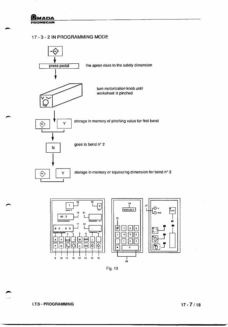
PROMECAM
17 - 3 - 2 IN PROGRAMMING MODE
press pedal the apron rises to the safety dimension
turn motorization knob until worksheet is pinched
storage in memory of pinching value for first bend
goes to bend n° 2
storage in memory or squeezing dimension for bend n° 2
20
L~ 18 21
1 40 . 5 ~ Y . I __ ",r'
18o . oo J-] Y_· J cb~~~~~~~
9 10 11 12 13 14 15 16
I.T.S - PROGRAMMING
24
I MAN~ALV I 25
~00[!J 8G~~ D0EJ0 [:] I 0 I I I
I 26
Fig. 13
7
L ~:m y It
• • ~I I
0 • ~ • I ffiJ---1
17-7/18

PAOMECAM
17-8/18
[Q--1 20
~ _N
18 21 I 40.5 }-1 LCJ _100')(
17 22
180.0 0 ~ y. ]
~~~~8i5"~ n NA ~ 1<7-
9 10 11 12 13 14 15 16
Fig. 10
r:-LJ 20
~ L~ ...-------. 18 21
I 4 0 . 5}-1 Y 0 0 .0 I __ coot
24
IMAN~ALY I 25
~G00 c:JG~~ O[2J ~0 [!]I 0 J
-1.
l J I
26
24
o 25
~G00 c:JG00 D~[]0 ~I 0 I
L I 9 10 11 12 13 14 15 16 I
Fig. 11
G--J9 _N
...-------. 18 21
I 38,0 }-J ~J ~ _~Of"
26
24 o 25
~G00 8~0~ D~~0 EJ I 0 1 I J
9 10 11 12 13 14 15 16 I 26
Fig. 12
27
L lf6:m 9 at
• •
~D • ~ IDJ-.f
27 ~ L n
mm
27 K6 L I't
mm
TECHNICAL MANUAL - Issue: 4/90

PROMECAM
17 - 4 FINDING BENDING DEPTH VALUE
~t 1
- -2,..,'4'
3 ____ STOP ,..,'4'
Position of switches on electrical control compartment
LT.S· PROGRAMMING
resetting, green indicator light is on
[!] -N
Return to bend n° 1
Automatic mode
The axes are positioned on bend n° 1 (wait for beep)
17-9/18

alMADA PROMECAM
17 .. 10/18
20 LG . ·Pn
[Q-J _N
_---. 18 21 r------.
140
.5 ~ Y 0.0 I
--==- ~ QltrX
25
24
IMAN~ALY I
~G00 8~0~ D~00 tJ I 0 I I J
9 10 11 12 13 14 15 16 I
r.-l 1i 20 ~ LG _N .p,.
__ 18 21 ...-----.
140.5~ Yo .. ol ~I!or"
26
Fig. 14
24
D 25
~G~0 8~~~ 0000 tJ l 0 J I J
9 10 11 12 13 14 15 16 I 26
Fig. 15
[Q-1 20 24
~ IAUT~MAI _N 18 21 I 40,5 ~ Y 0.0 I 25
-===- _x
~G~0 17 22
I 43 , 58 yf--J Y 0.0 ..,I
~~6~8~~ 8G0~ 0~~0 [;]1 0 1 I I
9 10 11 12 13 14 15 16 I 26
Fig. 16
27 ~ L n
mm
11 .
27 ~ L n mm
11
27
~:m L
~ II
~D ~
TECHNICAL MANUAL - Issue: 4/90

CiMADA PROMECAM
1 7 - 4 - 1 IN MANUAL MODe
Manual mode
identification of axis; window (24) indicates IMANUAl Y
press pedal the apron rises until the worksheet is squeezed
simultaneously press these two keys to obtain the angle of the first bend a -900
Programming mode
release pedal
I.T.S - PROGRAMMING
storage in memory of first bend a -900
window (17) indicates 143.58 1 for example
-y
goes to bend n° 2 ~ Y
Automatic mode
17-11/18
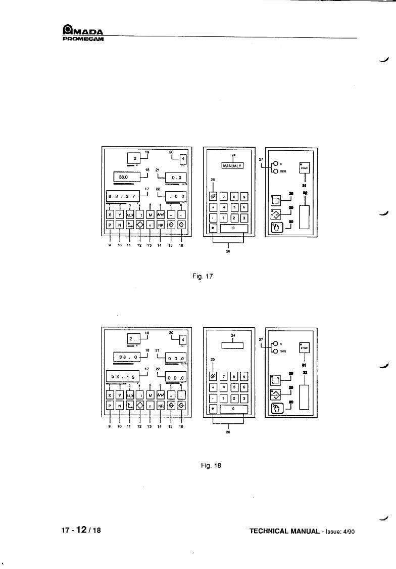
_MADA PROMECAM
[3-1 20 24 L[;,] IMAN~AlY I
27
~:m _N L 9 18 21
I 38.0 ~ Y 0.0 I 25 - ~oc.x
~G~~ at
17 22 • 16 2 • 3 7 ~ y. 0 oj • ~ 0 ~~~~~[5"6 8G0~ •
[]~~0 ~ NR ~ <$] 10
n GJ I 0 I ffiJ-1 I J
9 10 11 12 13 14 15 16 I 26
Fig. 17
EJ-1 20
24 2. LG 6 27
~:m -~ L 9 18 21
I 38. 0 ~ ~J 25 -- --==- ocr.
~G~~ 11
17 22 • 152.15y~ ~J ~
0 ~~6~~lJ~ 8G0~ ~ []~00 NR ~ ~J • n 81 0 I ffiJ-1
I I 9 10 11 12 13 14 15 16 I
26
Fig. 18
17-12/18 TECHNICAL MANUAL - Issue: 4/90
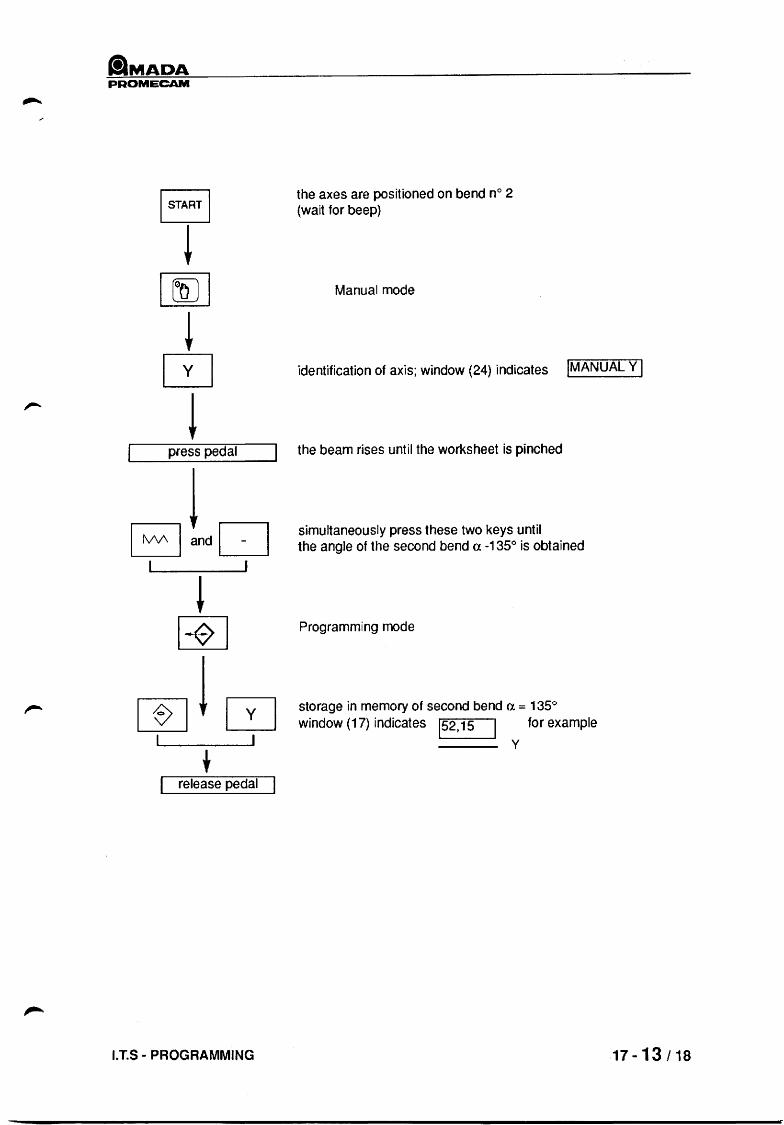
CilMADA PROMECAM
press pedal
E]tdD ~
[±]
rn!~ +
release pedal
I.T.S - PROGRAMMING
the axes are positioned on bend n° 2 (wait for beep)
Manual mode
identification of axis; window (24) indicates IMANUAL y I
the beam rises until the worksheet is pinched
simultaneously press these two keys until the angle of the second bend a -135° is obtained
Programming mode
storage in memory of second bend a = 1350
window (17) indicates 152,15 for example
y
.17-13/18
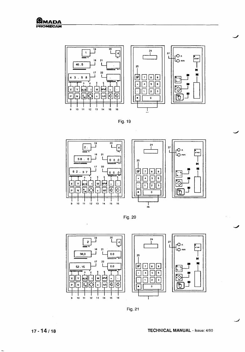
IlMADA PROMECAM
17-14/18
[Q--1 -"
24
6 25
~000 [:JG ~G 0800 EJl 0 J
l J 9 10 11 12 13 14 15 16 I
Fig. 19
r:--l 1r 20
~ L_(!1 .-------. 18 21
138. O~ ~~ __ eaX
24
6 25
~00~ c:JG~~ D8E10 tJl 0 J I J
9 10 11 12 13 14 15 16 I :;If;
Fig. 20
B-1 _N
24
6 .------. 18 21 . .-------.
38,0 ~ Y 0.0 I ~=- ""K
25
~00~ [JG~~ D8~0 tJl 0 J I J
9 10 11 12 13 14 15 16 I
Fig. 21
27 ~ L n mm
27 ~ L n mm
2 7
L ~:m y If .. •
~ 0 II
F01 I
mJjD
TECHNICAL MANUAL - Issue: 4/90
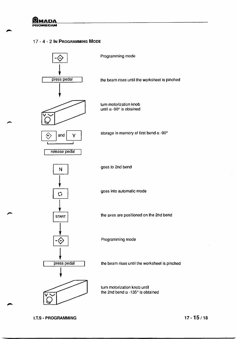
tiMADA PROMECAM
1 7 - 4 - 2 IN PROGRAMMING MODE
press pedal
~and~ , release pedal
press pedal
I.T.S - PROGRAMMING
Programming mode
the beam rises until the worksheet is pinched
turn motorization knob until (l -900 is obtained
storage in memory of first bend (l -900
goes to 2nd bend
goes into automatic mode
the axes are positioned on the 2nd bend
Programming mode
the beam rises until the worksheet is pinched
turn motorization knob until the 2nd bend a-135° is obtained
17-15/18

liMADA PROMECAM
17-16/18
20 LG .""
,...--------, 18 21 ....------.
1 40 . 5 ~ Y . I ~corX
17 22
"--14 -3 -. 5-8--'~ y"--,---']
[@J~~~~~6
24
D 25
~[!]0[!] c:JG0~ DDEJ0 c:J I 0 I I I
27 ~ L n
mm
9 10 11 12 13 14 15 16 I 26
Fig. 22
[Q-1 20 24
L~ D 27
~:m -~ L
~ 18 21 I 40.5 !-J Y . I 25 - _o~.
~[!]0[!] 11
17 22 • 143.
58 ~ LLJ •
~D [5[5" ~ ~ cfu ~ ~6 8G~G DDEJ0 ~
n NR ~ ~J c:J1 0 I m)..J I ,
9 10 11 12 13 14 15 16 I 26
Fig,23
TECHNICAL MANUAL -Issue: 4/90

laMADA PROMECAM
17 - 5 PRODUCTION
Position of switches on electrical control cabinet
3 ,-,STOPc~
I; (I)
tl /1'
resetting, green indicator light is on
Programming mode
return to bend n° 1 IT] -N
goes into automatic mode
the axes are positioned on bend n° 1 wait for end of positioning (beep)
You can now make the first bend.
After making the first bend, the numerical control is automatically placed on next bend. Always wait for the end-of-positioning beep before pressing the pedal again.
I. T.S - PROGRAMMING 17-17i18

PROMECAM
17-18/18 TECHNICAL MANUAL - Issue: 4/90

ttMADA PROMECAM
18 - ROUTINE MAINTENANCE OPERATIONS
18 -1 MACHINE MAINTENANCE:
Your press requires a minimum amount of maintenance; maintenance is chiefly limited to draining the hydraulic system.
A) HYDRAULIC SYSTEM - DRAINAGE
The hydraulic system in your press has distributor valves.
- The reliability of these valves depends above all on how clean the oil is.
We would like to remind you of a few basic rules:
- All hydraulic systems are contaminated, even before the system is assembled. - When operating the system, wear by abrasion generates further contamination. - The same applies when the system is topped up with new hydraulic fluid assumed to be clean.
For this reason, it is advisable not to stop up at short intervals, and not to drain the system too often.
- Well-filtered oil deteriorates quite slowly_ - Non-filtered oil increases the amount of pollution and clogs the filters more quickly.
TAKE EXTRA CARE WHEN FILLING. ONLY USE OIL THAT HAS BEEN FILTERED. THIS IS WHAT DETERMINES THE LIFE OF YOUR PRESS BRAKE
DRAINAGE
First drainage: : after 500 hours Next drainages: : every 1,500 hours
- Make sure that the lower beam is in the bottom position. - Remove the high-pressure filter element. - Remove the filling filter element. - Remove the drain plug and insert a hose in its place. - Drain tank completely.
FILLING
- Reassemble high-pressure filter (if necessary, change the element). - Insert drain plug. - Fill tank with Mobil DTE 25 oil (or any other oil with the exact same characteristics). Refer to the
table of machine characteristics to find out how much oil is needed. - When filling, filter the oil through a filter element of 5 absolute microns. - Check level, which should be between the minimum and maximum marks on the dipstick. - Insert filler plug
WARNING
THE PUMP MUST NEVER BE RUN WITHOUT ANY OIL IN IT.
I.T.S - ROUTINE MAINTENANCE OPERATIONS 18 - 1 16

ilMADA PROMECAM
B) TIGHTENING OF PIPES (IF NECESSARY)
The tightening torque applied to the pipe and hose fittings in the factory is sufficient to avoid any risk of them coming loose. Nevertheless, if a leak is detected, we advise you to contact our AfterSales Service before carrying out any operations on your own.
C) PERIOD OIL CHECK
Regu!arly check the level of the oil (approximately every 200 hours).
NOTE:
Technical characteristics of Mobil DTE 25 oil:
- Viscosity 44 Centistokes at 400 C - Viscosity 4° Engler at 50° C - Viscosity Index 102 - Pour point -180 C
18 - 2/6 TECHNICAL MANUAL - Issue: 4/90
J
--'

PROMIiCAM
18 - 2 REAR GAUGE ASSEMBLY MAINTENANCE
- Lubrication:
After dust removal, it is advisable to oil the slides on the rear gauge assembly once a week; to do this, use an oil with a viscosity of 3 to 5 E 50 0 C, 30/40 Cts. For the ball screw(s), we recommend using Tellus M oil, from Shell.
NOTE:
When working under special conditions, such as dusty, harmful or III-adapted environments, it is best to remove all impurities and deposits and to carefully clean the parts before lubricating.
Remember that all maintenance operations must be carried out with the machine turned OFF.
7 2
6
4
3
I.T.S - ROUTINE MAINTENANCE OPERATIONS 18 - 3/6

IlMADA PROMECAM
18 - 3 ADJUSTABLE INTERMEDIATE SETS
A· Function:
To allow fine setting of the tool line in order to obtain given conditions for minimum angle of phase differences over the length of the bend.
B - Purpose of adjustment:
The adjustment is made to compensate for the differences in penetration between the punch and the die. It is symbolised by the curve of the intermediate sets.
4J4-J4J W -2 -1 0
-3
The various adjustment curves for a given machine have the same general appearance. The values vary in amplitude, according to:
.. the type of material, its mechanical characteristics, expressed by its resistance to breaking under traction.
- the length and thickness of the worksheet to be bent (the design of adjustable intermediate sets can be used with all tools in the Amada range).
- the type of work being performed.
OBERVATION :
The intermediate curve on Amada machines is adjusted in relation to mean values, verified by the Amada technician when commissioning is done for the customer.
18 - 4/6 TECHNICAL MANUAL - Issue: 4/90

&MADA PROMECAM
C - Adjustment:
Preparation: on all the intermediate sets making up the tool line (Fig. 18.1):
- Loosen screw (item 6) (6 mm Allen wrench) to free the adjusting corner. - Slide the corner (item 9) as far down as it will go into the hole, to the right. - Slightly tighten screw (item 6) I then fully tighten tool spacer by means of the two screws (item
8).(key for six socket screw, 8). Flattening Intermediates:
Use either two identical die + punch lengths, or two special parts to produce the sketch below. These parts will be simultaneously and systematically moved to flatten each pair of intermediates.
XC48
~ L
~
150 :2
Adjust the press to a force of 20 tons.
Ra 1.6 v---
Ra 1.6 ....,,--
~ ... . 60 :0.2
~
(\J 0 d .. 0
" ...
"
j
~ ~
"
- Simultaneously flatten the two end intermediate sets, then the next two, and so on. If only one remains in the middle of the press, flatten it with a force of 10 tons.
I.T.S - ROUTINE MAINTENANCE OPERATIONS 18 - 5/6

PROMECAM
Adjustment of Dimension E on Dial Gauge
- Select the lowest intermediate, i.e. the one have the shortest E distance.
- Block its tightening corner (item 1), by means of screws. 2.
- Place travel dial indicator on lower beam. putting it in the middle of the intermediate set. and set needle on zero.
Adjust the following intermediates:
- by observing the values indicated in the curves below, which are mean adjusting values.
- or by customizing the adjustments in relation to the conditions of use and the results aimed at.
ITS 5011 2
ITS. 5 Q 12 0
ITS, 10/25
ITS 103
ns 125130
, 2 3 .- 5 I I·., , .. , r· ., , .. , r··, , .. , ·2 ·1 0 0 ·1 ·2
1 2 3 " 5 6 7 e ; 10 1 .. 1 I··, '··1 , •• , '·-1 1--' , •• , '··1 1·-1 1-·1 0000 0 0 0 00 0
1 2 3 .. 5 ,_., I··' I·.' I··' r··, ·2 ·1 ·1 0 0
1 2 3 .. 5 S 7 1··1 '··1 '··1 , •. , '··1 , •. , 1··1 ·2 ·2 ·1 ·1 ·1 ·1 0
I , .. , o
8
7 I· ·1 o
, .. , o
• , .. , o
.. 10 , .. , , .. , o -1
11 12
I··' , .. , ·1 ·2
Q 10 11 12 13 14 15 1·-1 , •. , 1--1 , .. , I··' 1 .. 1 1-·' o ·1 .. 1 ·1 ., -2 ·2
18 - 6 / 6 TECHNICAL MANUAL - Issue: 4190