Embed Size (px)
Citation preview

TM 10-3930-242-12
TECHNICAL MANUAL
OPERATOR AND ORGANIZATIONALMAINTENANCE MANUAL
FOR
TRUCK, LIFT, FORK, DIESEL ENGINE,PNEUMATIC TIRED WHEELS,
ROUGH TERRAIN 6,000 LB. CAPACITY,24 INCH LOAD CENTER
(ANTHONY MODEL MLT-6,ARMY MODEL MHE-200)
NSN 3930-00-903-0900,(CHRYSLER MODEL MLT-6CH,
ARMY MODEL MHE-202)NSN 3930-00-937-0220,
(ATHEY MODEL ARTFT-6,ARMY MODEL MHE-222)
NSN 3930-00-419-5744This copy is a reprint which includes current
pages from Changes 1 through 3.
HEADQUARTERS, DEPARTMENT OF THE ARMYJULY 1980

TM 10-3930-242-12
W A R N I N G
Death or severe injury may result if forklift truck engine is operated in an enclosed area withoutproviding adequate ventilation. Exhaust fumes contain carbon monoxide, a colorless, odorless,poisonous gas.
W A R N I N G
Do not smoke or use open flame in vicinity where batteries are being charged. The charging processgenerates hydrogen, a highly explosive gas.
W A R N I N G
Do not remove radiator cap unless engine has stopped and cooled to reduce pressure.
W A R N I N G
Always be alert for personnel in the area during operation of the forklift truck.
W A R N I N G
Always bleed off the pressure before operating any part of the hydraulic brake system by operatingthe brake pedal several times with the engine not running. Failure to observe this warning mayresult in severe injury to personnel.
W A R N I N G
Operation of this equipment presents a noise hazard to personnel in the area. The noise level ex-ceeds the allowable limits for unprotected personnel. Wear ear muffs or ear plugs.
W A R N I N G
Drycleaning solvent, P-D-680, used to clean parts, is potentially dangerous to personnel andproperty. Do not use near an open flame or excessive heat. The flash point of solvent is 138°F.
W A R N I N G
Compressed air used for cleaning purposes will not exceed 30 psi. Use only with effective chipguarding and personal protective equipment (goggles/shield, gloves, etc.)

CHANGE
No. 3
TM1O-393O-242-12C3
HEADQUARTERSDEPARTMENT OF THE ARMYWashington D. C., 26 July 1991
OPERATOR AND ORGANIZATIONALMAINTENANCE MANUAL
(NSN 3930-00-327-1575)
TRUCK, LlFT, FORK; DIESEL ENGINE, PNEUMATIC TIRED WHEELS,
ROUGH TERRAIN, 6,000 LB CAPACITY, 24 INCH LOAD CENTER
ANTHONY MODEL MLT 6-2 ARMY MODEL MHE-230
Current as of
TM 10-3930-242-12, 30 January 1987 is changed as follows:
1. Inside Front Cover. Add the following warning:
WARNING
If NBC exposure is suspected, all air filter media should be handled by personnel wearingprotective equipment. Consult your unit NBC Officer or NBC NCO for appropriate handIing or disposal instructions.
2. Remove old pages and insert new pages.
3. New or changed material is indicated by a vertical bar in the margin of the page.
Remove Pages Insert Pages
Pages 2-13 Pages 2-13
Pages 3-7 Page 3-7
Pages 3-7.0 thru 3-7.3. Add pages 3-8 thru 3-8.3
Page 3-9 thru 3-10 Page 3-9 thru 3-10
Page 4-4 Page 4-4
Page 4-9 thru 4-14 Page 4-9 thru 4-14
4. File this change sheet in front of the publication for reference purposes.


By Order of the Secretary of the Army:
GORDON R. SULLIVANGeneral, United States Army
Chief of Staff
Official:
PATRICIA P. HICKERSONBrigadier General, United States Army
The Ajutant General
Distribution:To be distributed IAW DA Form 12-25-E (Block No. 2227) Operator and Unit maintenance
requirements for TM 5-2410-223-24.


Changes In force: C 1 and C 2
CHANGE
No. 2
TM 10-3930-242-12C 2
HEADQUARTERSDEPARTMENT OF THE ARMY
Washington, D.C., 18 July 1989
OPERATOR AND ORGANIZATIONAL MAINTENANCE MANUAL
FOR
TRUCK, LIFT, FORK, DIESEL ENGINE, PNEUMATIC TIRED WHEELS,ROUGH TERRAIN; 6,000 LB CAPACITY, 24 INCH LOAD CENTER
(ANTHONY MODEL MLT-6, ARMY MODEL MHE-200)(NSN 3930-00-903-0900),
(CHRYSLER MODEL MLT-6CH, ARMY MODEL MHE-202)(NSN 3930-00-937-0220),
(ATHEY MODEL ARTFT-6, ARMY MODEL MHE-222)(NSN 3930-00-419-5744)
TM 10-3930-242-12, 31 July 1980, is changed as follows:
1. Remove old pages and insert new pages as indicated below.
2. New or changed material is indicated by a vertical bar in the margin of the page and by a vertical baradjacent to the illustration identification number.
Remove Pages Insert Pages
i and ii1-1 and 1-2
2-5 through 2-103-5 through 3-8
3-114-1 through 4-44-41 and 4-42
A-1C-1
D-9 and D-10
i and ii1-1 and 1-2
2-5 through 2-103-5 through 3-8
3-11/(3-12 blank)4-1 through 4-44-41 and 4-42
A-1/(A-2 blank)C-1/(C-2 blank)
D-9 and D-10
3. File this change sheet in front of the publication for reference purposes.
1

By Order of the Secretary of the Army:
Official:
CARL E. VUONOGeneral, United States Army
Chief of Staff
WILLIAM J. MEEHAN IIBrigadier General, United States Army
The Adjutant General
Distribution:
To be distributed in accordance with DA Form 12-25F, Operator and Unitmaintenance requirements for Fork Lift, 6000 LB Capacity, Rough Terrain,Pneumatic Tire, Diesel (Model MHE-200, 202, 222) Cumulative.
2

Change in force: C1 TM10-3930-242-12C1
CHANGE HEADQUARTERSDEPARTMENT OF THE ARMY
NO. 1 Washington, D. C., 30 January 1987
TECHNICAL MANUALOPERATOR AND ORGANIZATIONAL MAINTENANCE MANUAL
FORTRUCK, LIFT, FORK, DIESEL ENGINE, PNEUMATIC TIRED WHEELS,
ROUGH TERRAIN 6,000 LB CAPACITY, 24 INCH LOAD CENTER(ANTHONY MODEL MLT-6, ARMY MODEL MHE-200)
NSN 3930-00-903-0900,(ANTHONY MODEL MLT-6 WITH ROPS)
NSN 3930-01-054-3831,(CHRYSLER MODEL MLT-6CH, ARMY MODEL MHE-202)
NSN 3930-00-937-0220,(CHRYSLER MODEL MLT-6CH WITH ROPS
NSN 3930-01-053-4823,(ATHEY MODEL ARTFT-6, ARMY MODEL MHE-222)
NSN 3930-00419-5744,(ATHEY MODEL ARTFT-6 WITH ROPS)
NSN 3930-01-054-3830
TM 10-3930-242-12, July 1980 is changed as follows:
1. Remove old pages and insert new pages as indicated below.
Remove pages Insert Pages
Pages D-1 through D-7, APPENDIX D Pages D-1 through D-14, APPENDIX D
2. File this change sheet in front of the publication for reference purposes.
By Order of the Secretary of the Army:
JOHN A. WICKHAM, JR.General, United States Army
Chief of Staff
Official:
R.L. DILWORTHBrigadier General, United States Army
The Adjutant General
D i s t r i b u t i o n :
T O be distr ibuted in accordance wi th DA Form 12-25 , Operator and Organizat ionalM a i n t e n a n c e r e q u i r e m e n t s f o r T r u c k , L i f t , F o r k , D i e s e l E n g i n e , R o u g h T e r r a i n ,6,000 lb. capaci ty, Model MHE-200, 202, 222.


*TM 10-3930-242-12
TECHNICAL MANUAL HEADQUARTERSDEPARTMENT OF THE ARMY
NO.10-3930-242-12 WASHINGTON, DC, 31 July 1980
OPERATOR AND ORGANIZATIONAL MAINTENANCE MANUALFOR
TRUCK, LIFT, FORK, DIESEL ENGINE,
PNEUMATIC TIRED WHEELS, ROUGH TERRAIN
6,000 LB CAPACITY, 24 INCH LOAD CENTER
(ANTHONY MODEL MLT-6, ARMY MODEL MHE-200)
NSN 3930-00-903-0900
(CHRYSLER MODEL MLT-6CH, ARMY MODEL MHE-202)
NSN 3930-00-937-0220
(ATHEY MODEL ARTFT-6, ARMY MODEL MHE-222)
NSN 3930-00-419-5744
REPORTING ERRORS AND RECOMMENDING IMPROVEMENTS
You can help improve this manual. If you find any mistakes or if you know of a way toimprove the procedures, please let us know. Mail your letter, DA Form 2028(Recommended Changes to Publications and Blank Forms), or DA Form 2028-2,located in the back of this manual, direct to: Commander, U.S. ArmyTank-Automotive Command, ATTN: AMSTA-MB, Warren, Ml 48397-5000. A replywill be furnished to you.
ParagraphCHAPTER 1. INTRODUCTION
Section I. General . . . . . . . . . . . . . . . . . . . . . . . . . . . . . . . . . . . . . . . . . . . . . . . . . . . . .II. Description and data . . . . . . . . . . . . . . . . . . . . . . . . . . . . . . . . . . . . . . . .
CHAPTER 2. OPERATING INSTRUCTIONSSection I. Operating procedures, . . . . . . . . . . . . . . . . . . . . . . . . . . . . . . . . . . . . . . . . . . .
II. Operation under unusual conditions . . . . . . . . . . . . . . . . . . . . . . . . . . . . . . . . .
CHAPTER 3. OPERATOR/CREW MAINTENANCE INSTRUCTIONSSection I. Lubrication instructions ........ . . . . . . . . . . . . . . . . . . . . . . . . . . . . . . . . . . . .
II. Preventive maintenance checks and services . . . . . . . . . . . . . . . . . . . . . . . . . . .III. Troubleshooting ............. . . . . . . . . . . . . . . . . . . . . . . . . . . . . . . . . . .IV. Maintenance procedures....... . . . . . . . . . . . . . . . . . . . . . . . . . . . . . . . . . . . .
CHAPTER 4. ORGANIZATIONAL MAINTENANCE INSTRUCTIONSSection I. Service upon receipt of material.. . . . . . . . . . . . . . . . . . . . . . . . . . . . . . . . . . . . .
II. Movement toa new worksite . . . . . . . . . . . . . . . . . . . . . . . . . . . . . . . . . . . . . . . .III. Repair parts, special tools and equipment . . . . . . . . . . . . . . . . . . . . . . . . . . . . .IV. Preventive maintenance checks and services . . . . . . . . . . . . . . . . . . . . . . . . . . .V. Troubleshooting . . . . . . . . . . . . . . . . . . . . . . . . . . . . . . . . . . . . . . . . . . . . . . . . . .
1-1-1-5-1-6-1-8
2-1-2-52-6–2-13
3-1,3-23-3,3-4
3-53-6–3-13
4-1, 4-24-3, 4-44-5,4-64-7,4-8
4-9,4-10
l Tbis manual supersedes TM 10-3930-242-12, 24 December 1973, including all changes.
Change 2
Page
1-11-1
2-12-12
3-13-63-8
3-10
4-14-14-24-24-4
i

TM 10-3930-242-12
VI.VII.
VIII.IX.X.
XI.XII.
XIII.XIV.XV.
XVI.XVII.
XVIII.
APPENDIX A.B.C.D.E.F.
INDEX
Maintenance of lubrication system. . . . . . . . . . . . . . . . . . . . .Maintenance of Exhaust system. . . . . . . . . . . . . . . . . . . . . . . . . . . . .Maintenance of fuel system . . . . . . . . . . . . . . . . . . . . . . . . . . . . . .Maintenance of cooling system . . . . . . . . . . . . . . . . . . . . . . . . . . . . .Maintenance of electrical system... . . . . . . . . . . . . . . . . . . . . .Maintenance of controls and instruments. . . . . . . . . . . . .Maintenance of transmission. . . . . . . . . . . . . . . . . . . . . . . . . . . . .Maintenance of propeller shaft . . . . . . . . . . . . . . . . . . . . . . . . . . .Maintenance of brakes . . . . . . . . . . . . . . . . . . . . . . . . . . . . . . . . . . . . .Maintenance of wheels . . . . . . . . . . . . . . . . . . . . . . . . . .. . . . . . . . . . . . .Maintenance of steering system. . . . . . . . . . . . . . . . . . . .. . . . . . . . .Maintenance of hood and body... . . . . . . . . . . . . . . . . . . . .. . . . . . . . . . .Maintenance of hydraulic lift, pump, and tubing . . . . . . . . . . . . .
References . . . . . . . . . . . . . . . . . . . . . . . . . . . . . . . . . . . . . . . . . . . . . . . . . . . .Components of end items list. . . .. . . . . . . . . .. (None Authorized)Additional authorization list... . . . . . . . . . . . . . . . . . . . . . . . . .Maintenance allocation chart. . .. . . . . . . . . . . . . . . . . . . . . . . . . . . . .Repair parts and special tools list . . . . . . . . . . . . . . . . (None Authorized)Expendable supplies and materials list . . . . .. . . . . . . . . . . . . . . . . . . . .
. . . . . . . . . . . . . . . . . . . . . . . . . . . . . . . . . . . . . . . . . . . . . . . . . . . . . . . . . . . . . . . .
Paragraph4-11–4-154-16,4-17
4-18–4-224-23–4-314-32–4-424-43–4-524-53–4-56
4-574-58–4-62
4-634-64–4-674-68–4-704-71–4-77
A-1B-1C-1D-1E-1F-1
Page4-54-84-9
4-144-214-314-354-374-384-414-424-434-48
A-1B-1C-1D-1E-1F-1
I-1
ii Change 2

TM 10-3930-242-12
CHAPTER 1
INTRODUCTION
Section I.
1-1. Scope
This manual is for your use in operating andmaintaining rough terrain forklift trucks, Armymodels MHE-200, MHE-202, and MHE-222.
1-2. Maintenance Forms and Records
Equipment maintenance forms, and procedures fortheir use are contained in DA Pam 738-750.
1-3. Administrative Storage
a. Store equipment to provide maximumprotection from the elements and to provide accessfor inspection, maintenance, and exercising. An-ticipate removal or deployment problems and takesuitable precautions.
b. Take into account environmental conditionssuch as extreme heat or cold, high humidity,blowing sand, dust, loose debris, soft ground, mud,heavy snows, and take adequate precautions.
G E N E R A L
C. Establish a fire plan and provide for adequatefire fighting equipment and personnel.
d. Additional information can be found in TM740-90-1.
1-4. Destruction of Army Materiel to PreventEnemy Use
Procedures for the destruction of Army materiel toprevent enemy use are explained in TM 750-244-6.
1-5. Reporting Equipment Improvement Recom-mendations (EIR)
If your Rough Terrain Fork Lift Truck needs im-provement, let us know. Send us an EIR. You, theuser, are the only one who can tell us what you don’tlike about your equipment. Let us know why youdon’t like the design or performance. Put it on an SF368 (Quality Deficiency Report). Mail it to us at:Commander, U.S. Army Tank-Automotive Com-mand, ATTN: AMSTA-QRD, Warren, MI48397-5000. We’ll send you a reply.
Section II. DESCRIPTION AND DATA
1-6. Description
The rough terrain forklift truck (fig. 1-1 and 1-2) iscapable of operating over all types of terrain. It hasfront and rear axle steering which enables it to movesideways at 20° angles and gives the forklift ashorter turning radius. The forklift can be operatedin two-wheel or four-wheel drive, enabling it totravel through mud, snow, sand, and up steepgrades with equal mobility. The forklift has fordingcapability up to five foot waves. The body and forksfor the forklift may be tilted right or left in relationto the front axle. The forks are extended byhydraulically operated telescoping arms whichreach out, up, or down to handle loads. A hydrauliccylinder moves the forks right or left from center tolift off-center loads. The forklift has expanding tubetype hydraulic brakes, hydraulically operated powersteering, and a torque converter. The maintenanceparagraphs of this manual contain detaileddescriptions of its components.
1-7. Tabluated Data
a. Identification. The forklift has an identificationplate mounted on the left side of the hull which
specifies the nomenclature, shipping dimensions,model number, and engine manufacturer. The datafor this plate is listed under tabulated data (bbelow).
b. Tabulated Datu(1) Corps of Engineers “A” Plate.
Nomenclature. . . . . . . . . . . . . . . . .. . Truck, forklift, diesel. pneu-matic tired, 6,000 lb capacityat 24 inch load center
Engine manufacturer. . . . Detroit DieselModel . . . . . . . . . . . . . . . . . . . . .4-53-N
(2) Dimensions and WeightsCube . . . . . . . . . . . . . . . .1,763cu ftLength . . . . . . . . . . . . . . . . 228 in.Width . . . . . . . . . . . . . . . . . . . . 102 in.Height . . . . . . . . . . . . . . . . . . . 131 in.Weight:
Anthony and AtheyEmpty . . . . 23,000 lbMaximum 29,000 lb
ChryslerEmpty . . . 24,759 lbMaximum . 30,759 lb
Front wheel weights:Empty . . . . . . . . . . . . . . . . 8,645 lbLoaded . . . . . . . . . . . . . . . .l6,952 lb
Change 2 1-1

TM 10-3930-242-12
Rear wheel weights:Empty . . . . . . . . . . . . . . .15,915 lbLoaded . . . . . . . . . . . . . . .13,608 lb(3) Capacities.
Fuel tank . . . . . . . . . . . . . . . . 80 galHydraulic tank . . .. . . . . . . . 200 qtTransmission . . . . . . . . . . . . 24 qtCrankcase w/filter . . . . . . . . 16 qtRadiator . . . . . . . . . . . . . . . . 25 qtPlanetary drive . . . . .. . . . 4 qt eaDifferential . . . . . . . . . . . . . . 10 qt ea
(4) Wirng diagram. See figure 1-3.
1-8. Differences Among ModelsThis manual covers the Anthony Model MLT-6(MHE-200), the Chrysler Model MLT-6CH(MHE-202), and the Athey Model ARTFT-6(MHE-222). The differences among models exist inthe hydraulic cylinders and the common hardwarerelative to size, length, and type. Cylinder assemblyinternal parts are not interchangeable on Anthonyand Chrysler models, but are interchangeable onAnthony and Athey models. All hydraulic cylindersare interchangeable between models.
Figure 1-1. Rough terrain forklift truck, right front three-quarter view with shipping dimensions.
1-2 Change 2

TM 10-3930-242-12
Figure 1-2. Rough terrain forklift truck, left rear, three-quarter view.
1-3

figure 1-3
TM
10-3930-242-12
1-4

TM 10-3930-242-12
C H A P T E R 2
O P E R A T I N G I N S T R U C T I O N S
S e c t i o n I . O P E R A T I N G P R O C E D U R E S
WARNINGOperation of this equipment presents anoise hazard to personnel in the area. Thenoise level exceeds the allowable limitsfor unprotected personnel. Wear earmuffs or ear plus.
2-1. General
a. The instructions in this section are for theinformation and guidance, of personnel responsiblefor the operation of the rough terrain forklift truck.
WARNINGWhen climbing into the driver’s seat, becareful not bump head on roll overprotective structure (ROPS).
b. The operator must know how to perform everyoperation of which the forklift truck is capable. This
section gives instructions on starting, stopping,operating, and coordinating the basic motions toperform the specific tasks for which the forklift isdesigned. Since nearly every job presents a differentproblem, the operator may have to vary givenprocedures to fit the individual job.
c. The outside steering radius of the forklift truckis 32 feet in CRAMP steering mode and 43 feet inthe TWO WHEEL steering mode. If steering dif-ficulty is experienced in the CRAMP or CRABmodes of steering, it may be best to continueoperation in the TWO WHEEL steering mode.
2-2. Controls and Instrument.
The controls and instruments and their normalreadings are illustrated in figure 2-1.
2-1

TM 10-3930-242-12
2-2 Figure 2-1. Controls and instruments.

2-3. Starting
a Preparation for Starting.operation services in table 3-1.
NOTEStarting circuit is operative only whenFWD NEUT REV control lever is in
TM 10-3930-242-12
b. Starting. Refer to figure 2-2 and start the
Perform the before forklift.CAUTION
Continue operation only if there is not an
NEUT.
STEP 1:STEP 2:STEP 3:STEP 4:STEP 5:STEP 6:STEP 7:
STEP 8:
apparent loss of hydraulic oil or nounusual noise from the hydraulic pump toprevent damage to the forklift.
PLACE FWD-NEUT-REV LEVER IN NEUT POSITION.ENGAGE PARKING BRAKE.CHECK RADIATOR FAN CONTROL LEVER FOR PROPER POSITION.PLACE IGNITION SWITCH IN ON POSITION.PRESS ACCELERATOR PEDAL DOWN ONE THIRD DISTANCE.PRESS STARTER BUTTON.WARM ENGINE FOR THREE TO FIVE MINUTES AND OBSERVE INSTRUMENTS FORNORMAL READING (FIG. 2-1).REMOVE FOOT FROM ACCELERATOR PEDAL.
T A 0 7 2 3 0 7
Figure 2-2. Engine starting instructions.2-3

TM10-3930-242-12
2-4. Operation of EquipmentWARNING
Do not attempt to cross a side slope of30° or more with forklift in FOURWHEEL steering mode because theforklift may turn over.
a. General. The rough terrain forklift truck iscapable of operating over all types of terrain such as
snow, sand, and steep grades with equal mobility.b. Driving on Improved Surfaces. Refer to figure
2-3 for driving instructions while operating onimproved surfaces. After you put the drive selectorlever in TWO WHEEL DR, place the CRAB,CRAMP, and TWO WHEEL steering control leverin the TWO WHEEL steeering position and engagethe TWO WHEEL steering lock.
2-4

TM10-3930-242-12
STEP 1:STEP 2:
STEP 3:
STEP 4:STEP 5:
STEP 6:STEP 7:
START ENGINE (REF. PARA. 2-3).PULL FORK LIFT CONTROL LEVER TO RAISE FORKS 12 TO 18 INCHES OFF OPERATINGSURFACE.PLACE DRIVE SELECTOR LEVER (LOCATED TO REAR OF PARKING BRAKE) IN TWO-WHEEL DRIVE POSITION.DISENGAGE PARKING BRAKE AND APPLY SERVICE BRAKES.PLACE TRANSMISSION RANGE CONTROL LEVER IN DESIRED POSITION, DEPENDING ONWEIGHT OF LOAD. PLACT FWD-NEUT-REV CONTROL LEVER IN DESIRED POSITION.RELEASE SERVICE BRAKES.PRESS ACCELERATOR PEDAL AND PROCEED.
TA501572
Figure 2-.3 Driving on improued surfaces.
c.. Driving on Unimproved Surfaces. Refer to figure 2-5 for instructions for driving in snow or
figure 2-4 for driving instructions in surf. Refer to sand.
Change 2 2-5

TM 10-3930-242-12
NOTE:
STEP 1:
NOTE:
STEP 2:
STEP 3:STEP 4:
STEP 5:
STEP 6:NOTE:
CAUTION:
STEP 7:
CAUTION:N O T E :
NOTE:NOTE:
MAKE SURE FLYWHEEL HOUSING DRAIN PLUG IS IN PLACE, AND START ENGINE (FIG. 2.2).
PULL-FORK LIFT CONTROL LEVER TO RAISE FORKS JUST HIGH ENOUGH TOCLEAR THE SURF.IF TRANSPORTING A LOAD, PULL FORK EXTENSION CONTROL LEVER BACK TO RETRACTLOAD AS CLOSE TO CENTER OF TRUCK AS POSSIBLE TO BALANCE LOAD.PLACE DRIVE SELECTOR LEVER (LOCATED TO REAR OF PARKING BRAKE) IN FOUR-WHEEL DRIVE POSITION.RELEASE PARKING BRAKE AND APPLY SERVICE BRAKES.PLACE TRANSMISSION RANGE CONTROL LEVER IN DESIRED POSITION. NORMALLY A LOW-SPEED POSITION IS REQUIRED FOR SURF OPERATION.PLACE FWO-NEUT-REV CONTROL LEVER IN POSITION FOR DESIRED DIRECTION OFTRAVEL.RELEASE SERVICE BRAKE, PRESS ACCELERATOR PEDAL AND PROCEED.JUST BEFORE ENTERING SURF, PLACE RADIATOR FAN CONTROL LEVER IN OFF POSITION.WHEN LEAVING SURF, PLACE RADIATOR FAN CONTROL LEVER IN ON POSITION.DO NOT ALLOW WATER TO EXCEED 5-FOOT LEVEL MARK, MEASURED FROM CREST OFWAVES. PROCEED SLOWLY THROUGH SURF, KEEPING CONSTANTLY ALERT FOR HOLESAND OCEAN BOTTOM SOFTNESS. WHEN TIDE IS OUT, BOTTOM IS ESPECIALLY SOFT. IFTRUCK BEGINS TO MIRE, DO NOT STOP: MANEUVER UNTIL FREE. DIFFERENTIAL LOCK MAYBE USED WHEN NECESSARY TO GAIN ADDITIONAL TRACTION.OBSERVE RAMP OF LANDING CRAFT BEFORE ENTERING. ENTER FROM CENTER OF RAMPON WAVE RATHER THAN BETWEEN WAVES TO COMPENSATE FOR SHIFTING. KEEP SIGHTON TOP OF LEFT FORK. USE FORK TILT CONTROL LEVER TO BALANCE LOAD WHENGOING UP OR DOWN RAMP.BRAKES ARE LESS EFFECTIVE IMMEDIATELY AFTER LEAVING SURF.IF CONDITIONS WARRANT THE USE OF FOUR-WHEEL STEERING, ALINE FRONT WHEELS,PLACE FMD-NEUT-REV CONTROL LEVER IN FORWARD POSITION AND PLACE CRAB ANDCRAMP CONTROL LEVER IN DESIRED POSITION:CRAMPING IS NOT RECCMMENDED FOR SOFT TERRAIN.AFTER OPERATION IN SURF, SEE LO 10-3930-242-12-1, NOTE 6 AND NOTE 7.
2-6
Figure 2-4. Driving in surf
Change 2

TM 10-3930-242-12
NOTE: START ENGINE (FIG. 2-2).STEP 1: PULL FORK LIFT CONTROL LEVER TO RAISE FORKS 12 TO 18 INCHES ABOVE OPERATING
SURFACE.STEP 2: PIACE DRIVE SELECTOR LEVER (LOCATED TO REAR OF PARKING BRAKE) IN 4-WHEEL
DRIVE .STEP 3: RELEASE PARKING BRAKE AND APPLY SERVICE BRAKE .STEP 4: PLACE TRANSMISSION RANGE CONTROL LEVER IN POSITION FOR DESIRED SPEED,
DEPENDING ON WEIGHT OF LOAD AND TERRAIN CONDITIONS.STEP 5: PLACE FWD-NEUT-REV CONTROL LEVER IN POSITION FOR DESIRED DIRECTION OF
TRAVEL.STEP 6: RELEASE SERVICE BRAKE, PRESS ACCELERATOR PEDAL AND PROCEED.NOTE: DRIVE IN TRACKS ALREADY MADE IF POSSIBLE.STEP 7: IF FEASIBLE, APPROACH SAND DUNES DIRECTLY (AT RIGHT ANGLES). ATTEMPTS TO
SCALE AN INCLINE SIDEWAYS AND UPWARD USUALLY RESULT IN DOWNWARD SLIPPAGE.IF A DIRECT APPROACH CANNOT BE MADE, USE THE OSCILLATION CONTROL LEVER TOBALANCE LOAD DURING THE ASCENT.
WARNING: DO NOT ATTEMPT TO CROSS A SLOPE OF 30° OR MORE BECAUSE THE TRUCK MAYOVERTURN.
NOTE: DIFFERENTIAL LOCK MAY BE USED WHEN NECESSARY TO GAIN ADDITIONAL TRACTION INSAND OR SNOW.
TA501736
Figure 2-.5. Driving in sand or snow.
Change 2 2-7
TM 10-3930-242-12
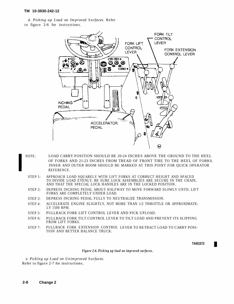
d. Picking up Load on Improved Surfaces. Referto figure 2-6 for instructions.
NOTE:
STEP 1:
STEP 2:
STEP 3:STEP 4:
STEP 5:STEP 6:
STEP 7:
LOAD CARRY POSITION SHOULD BE 20-24 INCHES ABOVE THE GROUND TO THE HEELOF FORKS AND 21-23 INCHES FROM TREAD OF FRONT TIRE TO THE HEEL OF FORKS.INNER AND OUTER BOOM SHOULD BE MARKED AT THIS POINT FOR QUICK OPERATORREFERENCE.
APPROACH LOAD SQUARELY WITH LIFT FORKS AT CORRECT HEIGHT AND SPACEDTO DIVIDE LOAD EVENLY. BE SURE LOCK ASSEMBLIES ARE SECURE IN THE CHAIN,AND THAT THE SPECIAL LOCK HANDLES ARE IN THE LOCKED POSITION.DEPRESS INCHING PEDAL ABOUT HALFWAY TO MOVE FORWARD SLOWLY UNTIL LIFTFORKS ARE COMPLETELY UNDER LOAD.DEPRESS INCHING PEDAL FULLY TO NEUTRALIZE TRANSMISSION.ACCELERATE ENGINE SLIGHTLY, NOT MORE THAN 1/2 THROTTLE OR APPROXIMATE-LY 1500 RPM.PULLBACK FORK LIFT CONTROL LEVER AND PICK UPLOAD.PULLBACK FORK TILT CONTROL LEVER TO TILT LOAD AND PREVENT ITS SLIPPINGFROM LIFT FORKS.PULLBACK FORK EXTENSION CONTROLTION AND BETTER BALANCE TRUCK.
LEVER TO RETRACT LOAD TO CARRY POSI-
Figure 2-6. Picking up load on improved surfaces.
e. Picking up Load on Unimproved Surfaces.Refer to figure 2-7 for instructions.
TA501573
2-8 Change 2

TM 10-3930-242-12
NOTE :
STEP 1:
STEP 2:
STEP 3:
STEP 4:
STEP 5:
STEP 6:
STEP 7:STEP 8:
STEP 9:
LOAD CARRY POSITION SHOULD BE 20-24 INCHES ABOVE THE GROUND TO THE HEELOF FORKS AND 21-23 INCHES FROM TREAD OF FRONT TIRE TO THE HEEL OF FORKS.INNER AND OUTER BOOM SHOULD BE MARKED AT THIS POINT FOR QUICK OPERATORREFERENCE.
APPROACH LOAD SQUARELY AND STOP TRUCK (FIG. 2-9), LEAVING AMPLE ROOM TOMAKE FORK ADJUSTMENTS.PUSH FORK EXTENSION CONTROL LEVER FORWARD TO EXTEND FORKS LONGITUDIN-ALLY.PUSH FORK TILT CONTROL LEVER FORWARD TO TILT FORK CARRIAGE TO VERTICALPOSITION.PUSH FORK LIFT CONTROL LEVER FORWARD AND LOWER FORKS TO CORRECT HEIGHT.SEE THAT FORKS ARE SPACED TO DIVIDE LOAD EVENLY, IF NECESSARY, USE FORKSIDE SHIFT CONTROL LEVER TO PROPERLY POSITION FORKS FROM SIDE TO SIDE.DEPRESS INCHING PEDAL ABOUT HALFWAY TO DRIVE TRUCK FORWARD SLOWLY UNTILFORKS ARE COMPLETELY UNDER LOAD.DEPRESS INCHING PEDAL FULLY TO NEUTRALIZE THE TRANSMISSION AND ACCELERATETHE ENGINE NOT MORE THAN 1/2 THROTTLE OR APPROXlMATELY 1500 RPM.PULLBACK FORK LIFT CONTROL LEVER AND PICK UPLOAD.PULLBACK FORK TILT CONTROL LEVER TO TILT LOAD AND PREVENT ITS SLIPPINGFROM FORKS.PULLBACK FORK EXTENSION CONTROL LEVER TO RETRACT LOAD TO CARRY POSITIONAND BETTER BALANCE TRUCK.
TA501574
Figure 2-7. Picking upload on unimproved surfaces.
f. Depositing Load. Refer to figure 2-8 for in-structions.
Change 2 2-9

TM 10-3930-242-12
STEP 1:STEP 2:STEP 3:
STEP 4:STEP 5:
STEP 6:
STEP 7:
STEP 8:STEP 9:
STEP 10:
CAREFULLY DRIVE UP TO POSITIO WHERE LOAD IS TO BE DEPOSITED.DEPRESS INCHING PEDAL.PUSH FORK EXTENSION CONTROL LEVER FORWARD TO EXTEND FORKSLONGITUDINALLY.PUSH FORK TILT CONTROL LEVER FORWARD TO TILT CARRIAGE TO VERTICAL POSITION.IF LOAD IS TO BE DEPOSITED ON GROUND LEVEL, PUSH FORK LIFT CONTROL LEVERFORWARD AND ALLOW LOAD TO LOWER SLOWLY TO RESTING PLACE. CONTINUE TOLOWER FORKS UNTIL THEY CAN BE EASILY WITHDRAWN FROM PALLET. THEN PROCEEDWITH STEP 10.IF LOAD IS TO BE DEPOSITED ON A TIERED STACK, PULL FORK LIFT CONTROL LEVERBACK UNTIL LOAD REACHES DESIRED HEIGHT ABOVE TIER, THEN PROCEED WITH STEPS7 THROUGH 10.RELEASE INCHING PEDAL ABOUT HALFWAY AND INCH TRUCK FORWARD UNTIL LOAD ISABOVE ITS RESTING PLACE.DEPRESS ’INCHING PEDAL.PUSH FORK LIFT CONTROL LEVER FORWARD AND LOWER LOAD CAREFULLY TO ITSRESTING PLACE. CONTINUE TO LOWER FORKS UNTIL THEY CAN BE EASILY WITHDRAWNFROM PALLET.PLACE FWD-NEUT-REV CONTROL LEVER IN REV AND RELEASE INCHING PEDAL.
TA072391Figure 2-8. Depositing load.
2-10

TM 10-3930-242-12
2-5. Stopping
a. Normal Stopping.stopping instructions.
Refer to figure 2-9 for
STEP 1:STEP 2:STEP 3:STEP 4:
STEP 5:
REMOVE FOOT FROM ACCELERATOR.DEPRESS BRAKE PEDAL SLOWLY AND BRING TRUCK TO GRADUAL STOP.PLACE FWD-NEUT-REV CONTROL LEVER IN NEUT POSITION.IF TRUCK IS TO BE PARKED, APPLY PARKING BRAKE, ALLOW ENGINE TO IDLE3-5 MINUTES THEN PULL UP ON NORMAL ENGINE SHUTOFF HANDLE.TURN OFF IGNITION SWITCH.
TA072392
Figure 2-9. Forklifts topping instructions.
b. Emergency Stopping . Pull up on theEMERGENCY STOP CONTROL to stop theengine in enemergency.
2-11

TM 10-3930-242-12
NOTETo restart the engine a f ter theEMERGENCY STOP CONTROL hasbeen used, push the EMERGENCY
Section II. OPERATION
2-6. Operation in Extreme Cold (below 0°F.(–18° C))
S T O P C O N T R O L d o w n . T h eEMERGENCY STOP CONTROL resetlever, located on left side of engine mustbe pushed toward the cylinder block.
UNDER UNUSUAL CONDITIONS
foreign materials. If fuel filters requir servicing,report to organizational maintenance.
a. Check coolant level and add coolant as f. Lubricate in accordance with current
specified in table 2-1. Have organizational main- lubrication chart (fig. 3-1).
tenance perform specific gravity test to make sureg. Pull up on either primer button, engage starter,
that antifreeze solution is correct for lowest tem- and with the engine turning, press the ether button
perature expected. down. If combustion does not occur, repeat the
b. Inspect cooling system. Correct or report any priming process with the starter engaged.
leaks. h. In extremely cold weather it is advisable to
c. Keep batteries fully charged. After adding give the engine one priming charge before engaging
distilled water to the batteries, run the engine for at the starter. Then proceed as in g above.
least 15 minutes. i. Allow the engine to reach normal operating
d. Keep fuel tank full when not in operation. temperature before applying load.
e. Drain secondary fuel filters of water and
Table 2-1. Freezing Points, Composition, and Specific Gravities of Military Antifreeze Material
Lowestexpectedambient
tempºF.
+20
+100
–10– 20– 30– 40– 50– 60–75
Pints ofinhibitedglycol pergallon ofcoolant1
Compound, antifreeze2
11/2 Issued full strength and ready mixed for 0 to –65º F temperatures 1.022for both installation and losses.
22¾3¼3½44 ½Arctic
antifreezepreferred
1.0361.0471.0551.0621.0671.073
Ethylene g lyco lcoo lant so lut ionspec i f i c gravi ty
at 68º F.³
1 Maximum protection is obtained at 60 percent by volume (4.8 pints of ethylene glycol per gallon of solution).2 Military Specification M IL-C-11755 Arctic type, non-volatile antifreeze compound is intended for use in the cooling system of
liquid cooled internal combustion engines. It is used for protection against freezing primarily in Arctic regions where the ambienttemperature remains for extended periods of time close to – 40º F., or below, to as low as – 90° F.
‘ Use an accurate hydrometer. To test hydrometer, use 1 part ethylene glycol type antifreeze to 2 parts water. This should produce ahydrometer reading of 0° F.
2-7. Starting Aid (2) perform normal starting procedures (paraa. General The starting aid is a pressurized 2-3).
system used to inject a highly volatile fluid into teh (3) If engine fails to start, refer toengine air intake system. This is to facilitate troubleshooting table (table 3-2).starting when ambient temperatures are below 2-8. Operation in Extreme Heat40° F. The replaceable pressurized cylinder contains WARNINGsufficient fluid for 75-150 starts.
b. Operating the Starting Aid.Be extremely careful when removing the
(1) Operate starting aid control for about 2radiator filler cap of a hot engine. Releaseof pressure may cause violet boiling and
seconds. Wait 3 seconds before cranking engine. serious injury to personnel.
2-12

TM10-3930-242-12
a. Insure that radiator filler cap seals properly.The boiling point of the coolant is raised as thesystem pressure is increased.
b. Check coolant level frequently and add coolantas necessary. Use standard ethylene glycol mixtureas specified in table 2-1.
c. Remove all obstructions and foreign materialcollected on radiator fins and air passages.
d. Do not overfill fuel tank. Make sure fuel filtersare clean.
WARNING
If NBC exposure is suspected, all air filtermedia should be handled by personnelwearing protective equipment. Consultyour unit NBC Officer or NBC NCO forappropriate handling or disposal procedures.
e. Have air cleaner cleaned and serviced.
2-9. operation in Dusty or Sandy Area
a. Clean all grease fittings after operation.b. Lubricate in accordance with figure 3-1.c. Check oil filter and engine oil frequently.d. Have air cleaner serviced often.e. Have fuel filters cleaned and serviced.
2-10. Operation in Salt Water Areaa. Keep all lubrication points clean and well
lubricated.
b. Keep all wiring and ignition terminals free ofcorrosion.
c. Keep forklift as clean as possible.
d. After operation is complete, wash with freshwater. Lubricate in accordance with figure3-1. Check all gear cases for water contamination.If contamination is found, (evidenced by a milkycolor of lubricant) drain, flush, and refill.
2-11. Operation Under Rainy or Humid Conditions
a. Keep fuel tank full at all times.b. Wash forklift truck after operation.
2-12. Operation at High Altitudea. Check coolant level frequently and add coolant
as necessary.NOTE
The engine will operate less efficiently athigh altitudes.
b. Observe engine instruments while operatingfor any indication of trouble.
2-13. Operation in Snow
a. Keep fuel tank full at all times. Keep snowaway from filler where servicing fuel tank.
b. Clean all snow from operating controls andfrom steps.
Change 3 2-13


TM10-3930-242-12
C H A P T E R 3
O P E R A T O R / C R E W M A I N T E N A N C E I N S T R U C T I O N S
S e c t i o n I . L U B R I C A T I O N I N S T R U C T I O N S
WARNINGDrycleaning solvent, P-D-680, used toclean parts is potentially dangerous topersonnel and property. Do not use nearopen flame or excessive heat. The flashpoint of solvent is 138° F.
3-1. General Lubrication Information
This section contains information on lubricationinstructions not covered in the current lubricationorder. Refer to the current lubrication order for allother instructions.
3-2. Detailed Lubrication Information
a. Care of Lubricants. Keep all lubricants inclosed containers and store in a clean, dry place,away from heat. Keep container cover clean and ingood condition. Keep dust, dirt, and all other foreignmaterial out of the lubricant. Keep all lubrication
equipment clean and ready for use.b. Cleaning. Keep all external parts, that do not
require lubrication, free of lubricants. Wipe alllubrication points clean before lubricating theforklift truck. Clean all lubrication points of ex-cessive lubricant after servicing to prevent a build-up or accumulation of foreign matter.
CAUTIONExcess ive lubr icat ion may causeequipment failure or damage to movableparts.
c. Points of Lubrication. Service the forklift truckat the intervals given in figure 3-1.
d. Intervals of Lubrication. The intervals oflubrication specified in the lubrication order chart(fig. 3-1) are based on operation under normalconditions. Modifications of these recommendedintervals may be required under unusual operatingconditions.
3-1
TM10-3930-242-12
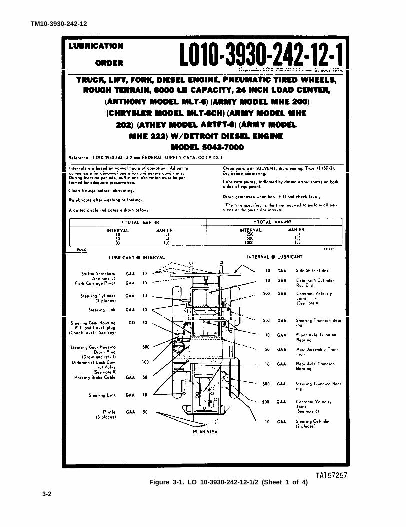
Figure 3-1. LO 10-3930-242-12-1/2 (Sheet 1 of 4)
3-2

TM10-3930-242-12
Figure 3-1. LO 10-3930-242-12-1/-2 (Sheet 2 of 4)3 - 3

TM 10-3930-242-12
Figure 3-1. LO 10-3930-242-12-1/-2 (Sheet 3 of 4)3-4

TM 10-3930-242-12
Figure 3-1. LO 10-3930-242-12-1/-2 (Sheet 4 of 4)3-5

TM10-3930-242-12
3-3. Maintenance Forms and Records
SECTION II. OPERATOR/CREW PREVENTIVE MAINTENANCECHECKS AND SERVICES (PMCS)
Every mission begins and ends with the paperwork.There isn’t much of it, but you have to keep it up.The forms and records you fill out have several uses.They are a permanent record of the services, repairs,and modifications made on your equipment. Theyare reports to organizational maintenance and toyour commander. They are also a checklist for youwhen you want to know what is wrong with the equip-ment after its last use, and whether those faults havebeen fixed. For the information you need on formsand records, see DA Pam 738-750.
3-4. General
Your Preventive Maintenance Checks and ServicesTable lists the inspections and care of your equip-ment required to keep it in good operating condition.
3-4.1. Operator/Crew Preventive MaintenanceChecks and Services
a. The number column of your PMCS is thesource for the number used on the TM Number Col-umn on DA Form 2404.
b. The interval column of your PMCS Table tellsyou when to do a certain check or service.
(1) Before you operate. Perform your before(B) PMCS. Always keep in mind the WARNINGSand CAUTIONS.
(2) While you operate. Perform your during(D) PMCS Always keep in mind the WARNINGSand CAUTIONS.
(3) After you operate. Be sure to perform yourafter (A) PMCS. Always keep in mind theWARNINGS and CAUTIONs.
(4) Once a week. Perform your weekly (W)PMCS. Always keep in mind the WARNINGS andCAUTIONS.
c. The procedure column of your PMCS Tabletells you how to do the required checks and services.Carefully follow these instructions. If you do not havethe tools, or if the procedure tells you to, have organ-izational maintenance do the work.
d. If your equipment does not perform as re-quired, refer to the troubleshooting section in thismanual for possible problems. Report any malfunc-tions or failures on the proper DA Form 2404 orrefer to DA Pam 783-750.
NOTE
The terms ready/available and mission capa-ble refer to the same status: Equipment is onhand and is able to perform its combat mis-sions (see DA Pam 738-750).
e. Equipment is not ready/available if: column.This column tells you when and why your equipmentcannot be used.
f. Always do your PMCS in the same order so itgets to be a habit. Once you’ve had some practice,you will spot anything wrong in a hurry.
g. When you do your PMCS, take along a rag ortwo.
h. While performing PMCS, observce allWARNINGs and CAUTIONs preceding those opera-tions which could endanger your safety or result indamage to the equipment.
WARNING
Dry cleaning solvent, P-D-680, is toxic andflammable. Wear protective goggles andgloves and use only in a well-ventilated area.Avoid allowing solvent to contact skin, eyes,and clothes, and don’t breathe vapors. Donot use near open flame or excessive heat. Ifyou become dizzy while using cleaning sol-vent, get fresh air immediately and getmedical aid. If solvent comes in contact withskin or clothing, wash with water. If solventgets in your eyes, flush eyes with water andget medical aid immediately. Flash point ofsolvent is 100º-138ºF (38º-59ºC).
(1) Keep it clean. Dirt, grease, oil and debrisonly get in the way and may cover up a serious prob-lem. Clean as you work and as needed. Use drycleaning solvent (P-D-680) to clean metal surfaces.Use soap and water when you clean rubber or plasticmaterial.
(2) Bolts, nuts, and screws. Check that theyare not loose, missing, bent, or broken. You can’t trythem all with a tool, of course, but look for chippedpaint, bare metal, or rust around bolt heads. Tightenany bolt, nut, or screw that you find loose.
(3) Welds. Look for loose or chipped paint,rust or gaps where parts are welded together. If youfind a bad weld, report it to organizational mainte-nance.
(4) Electric wires and connectors. Look forcracked or broken insulation, bare wires, and loose
3-6 Change 2

or broken connectors. Report damaged or loose wir-ing to organizational maintenance.
(5) Hoses and fluid lines. Look for wear, dam-age, and leaks. Make sure clamps and fittings aretight. Wet spots show leaks, but a stain around a fit-ting or connector can also mean a leak. If leakagecomes from a loose fitting or connector, tighten thefitting or connector. If something is broken or wornout, report it to organizational maintenance.
(6) Fluid level. Vehicle must be on levelground in order to get correct fluid level measure-ment.
i. It is necessary for you to know how fluid leaksaffect the status of your equipment. The followingare definitions of the types/classes of leakage youneed to know to be able to determine the status ofyour equipment. Learn and be familiar with them,and REMEMBER —when in douubt, notify your su-pervisor.
TM10-3930-242-12
Leakage Definitions for Opera tor/Crew PMCSClass I Seepage of fluid (as indicated by wetness or
discoloration) not great enough to formdrops.
Class II Leakage of fluid great enough to form drops,but not enough to cause drops to drip from theitem being checked/inspected.
Class III Leakage of fluId great enough to form dropsthat fall from the item being checked/in-spected.
CAUTION
Equipment operation is allowable with minorleakages (Class I or II). Of course, consid-eration must be given to the fluid capacity inthe item/system being checked/inspected.When operating with Class I or II leaks, con-tinue to check fluid levels as required onyour PMCS. Class III leaks should be re-ported to your supervisor or to organizationalmaintenance.
ItemNo.
1
2
Table 3-1. Operator/Crew Preventive Maintenance Checks and Services
NOTE: Within designated Interval, these checks are to be
B— Before
performed in the order listed.
D – D u r i n g A–After W–Weekly
Interval
D A W
Item To Be InspectedProcedure: Check for and have repaired, filled, or
adjusted as needed.
IMPORTANT - PERFORM WEEKLY (W) ASWELL AS BEFORE (B) OPERATIONS PMCS IF:a. You are the assigned operator and have not op-
erated the vehicle since the last weekly PMCS.b. You are operating the vehicle for the first time.
EXTERIOR OF VEHICLE
a. Check for fuel, engine oil, coolant and hy-draulic leaks or appearance of leakage.
b. Visually check Roll Over Protective Structure(ROPS) for damage, bends, or cracks in weldment.
c. Visually check forks, carriages, and side shif-ter frame for cracked, bent, or broken componentsor frame members.
d. Visually check wiring harness and connec-tions for frayed, broken, or burned wires.
TIRES AND WHEELS
a. Check tires for excessive wear, cuts, or abra-sions, embedded foreign objects, and obviously lowor flat condition. (Ref TM 9-2610-200-24)
Equipment is not Ready/Available If:
Class III leaks are evident.
Damage, bends, or cracksin weldment.
Forks, carriage, or sideshifter frame cracked,bent, or broken.
Wiring is frayed, broken,or burned.
Tires have cuts or abra-sions which would result intire failure. Tires are low,flat, or missing.
Change 2 3-7

TM 10-3930-242-12
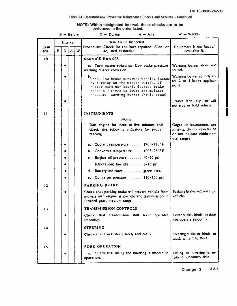
Table 3-1. Operator/Crew Prventive Maintenance Checks and Services - Continued
NOTE: Within designated interval, these checks are to beperformed in the order listed.
3-8 Change 3
TM 10-3930-242-12
Tabel 3-1. Operator/Crew Preventive Maintenance Checks and Services - Continued
NOTE: Within designated interval, these checks are to beperformed in the order listed.
Change 3 3-8.1

TM 10-3930-242-12
Table 3-1. Operator/Crew Preventive Maintenance Checks and Services - Continued
NOTE: Within designated interval, these checks are to beperformed in the order listed.
3-8.2

TM10-3930-242-12
Table 3-I. Operator/Crcw preventive Maintenance Checks and Semites–Conthwed
NOTE: Within designated Interval, these checks are to beperformed in the order listed.
B - B e f o r e D - D u r i n g A - A f t e r W - W e e k l y
Interval Item To Be InspectedItem Procedure: Check for and have repaired, filled, or Equipment is not ReadyNo. B D A W adjusted as needed. Available If:
21 RADIATOR
WARNINGPressurized cooling system. Remove capslowly and only when engine is cool or pain-fud burns could result.
Visually check coolant level and ensure that coolant Radiator obviously low oris 1-1/2 to 2 inches below neck. empty. Refer to instrument
checks.
22 FUEL SYSTEM
CAUTIONIn freezing weather, drain water from pri-mary falter after operation or damage toequipment could result.
Drain water and contaminants from primary falter.Frozen water in fuel system could cause damage toequipment.
Section III. TROUBLESHOOTING
3-5. General actions. If a malfunction is not listed or is not
a. This section contains troubleshootinginformation for locating and correcting most of theoperating troubles which may develop in the roughterrain forklift truck. Each malfunction for anindividual component, unit, or system is followed bya list of tests or inspections which will help you todetermine corrective actions to take. You shouldperform the tests or inspections and correctiveactions in the order listed.
b. This manual cannot list all malfunctions thatmay occur, nor all tests or inspections and corrective
corrected by listed corrective actions, notify yoursupervisor.
c. Table 3-2 lists the common malfunctions whichyou may find during the operation or maintenance ofthe rough terrain forklift truck or its components.You should perform the tests or inspections and thecorrective actions in the order listed.
NOTE
Before you use this table, be sure you haveperformed all applicable operating checks.
3-8.3


TM 10-3930-242-12
Table 3-2. Operator/Crew Troubleshooting
MalfunctionTest or inspection
Corrective action
1. ENGINE FAILS TO STARTStep 1. Check for hose, corroded or damaged battery cables and connection. Clean corroded cables. Tighten loose connections
Step
Step
Step
and report damaged cables to organizational maintenance.2. Check to be sure that engine shut-off is pushed down and that lever at the governor housing is in the start position.Adjust cable as necessary.3. Check to be sure the emergency stop is in operating position at the engine blower.Reset if required.
If NBC exposure is suspected, all air filter media should be handledby personnel wearing protective equipment. Consult your unit NBCOfficer or NBC NCO for appropriate handling or disposal procedures.
4. Check for air cleaner intake restrictions.Correct as necessary.5. Check for empty fuel tank.Fill as required.
Step
2. ENGINE OPERATES ERRATICALLYStep 1. Check for clogged air cleaner.
Have air cleaner serviced.Step 2. Check for condensation and fuel contamination.
Drain condensation from fuel filters before engine. Report evidence of fuel contamination to organizational main-tenance.
Step 3. Notify supervisor and organiazational/direct support maintenance to check governor gap.3. ENGINE LACKS POWER
Step 1. Check for clogged air cleaner.Have air cleaner serviced.
Step 2. Check fuel fiiters for contamination.Drain condensation from fuel filters before starting engine. Report evidence of fuel contamination to organizational main-tenance.
Step 3. Notify supervisor and organizational/direct support maintenance to check fuel rack and govenor operation.4. ENGINE OVERHEATS
Step 1. Check radiator for low level of coolant.Allow engine to cool and fill with coolant.
Step 2. Check fan belt for looseness.Report a hose or damaged fan belt to organizational maintenance.
Step 3. Check radiator for free airflow.Clean radiator fins if required.
5. ENGINE EXHAUST SMOKE EXCESSIVEStep 1. Check for clogged air cleaner.
Have air cleaner serviced.6. ENGINE OIL CONSUMPTION EXCESSIVE
Step 1. Inspect engine compartment for oil leaks.Do not continue operation if oil leak is likely to reduce engine off below a safe operating level. Report leaks to organisationalmaintenance.
7. STEERING ERRATICStep 1. Check for rear steering cross-shaft binding in tube.
Do not continue operation if the erratic stearing constitutes a threat to personnel or may result in equipment damage. Reportto organizational maintenance.
Step 2. Check for low level of hydraulic fluid.Report low hydraulic fluid level to organizational maintenance.
8. BATTERY FAILS TO MAINTAIN CHARGEStep 1. Check for low level of electrolyte.
Fill battery with distilled water.Step 2. Visually inspect battery for damage such as loose terminal posts or warped internal plates.
Report unserviceable batteries to organizational maintenance.
Change 3 3-9

TM10-3930-242-12
Section IV. OPERATOR/CREW MAINTENANCE PROCEDURES
3-6. Engine Air Cleaner Inspection
WARNINGIf NBC exposure is suspected, all air filter me-dia should be handled by personnel wearingprotective equipment. Consult your unit NBCOfficer or NBC NCO for appropriate handlingor disposal procedures.
Loosen the clamp and remove the cup. Remove theelement and inspect it for excessive accumulation ofdirt. Remove the cup dust trap and inspect for
excessive accumulation of dust. Report toorganizational maintenance for Servicing.
3-7. Ether Primer
Refer to figure 3-2 and service the ether primer.
Figure 3-2. Ether primer servicing,3-8. Battery
Visually inspect batteries for damage, such as loose above the plates. Replace vent cap. Inspect cableselectrolyte. The electrolyte should be one-half inch
terminal posts or warped internal plates. Remove and battery holddown hardware for corrosion.battery cell vent caps (fig. 3-3) and check the level of
3-10 Change 3

TM 10-3930-242-12
Figure 3-4 Exhaust manifold and flange.
Figure 3-3. Battery.
3-9. Fuel Tank
a. Inspection. Inspect the fuel tank for dents andleaks.
b. Service. Fill fuel tank with diesel fuel ac-cording to table 3–3.
Table 3-3. Fuel Use According to Temperture
Temperature range Fuel
+20º F. and warmer VVF-800 Type DF2– 25° F. and warmer VVF-800 Type DF1– 25° F. and colder VVF-800 Type DFA
3-11. Exhaust Manifold and Flange
Inspect exhaust manifold and flange for cracks,nicks, and damaged parts. Refer to figure 3-4.
3-12. Muffler and Exhaust Pipe
Inspect muffler and exhaust pipe for cracks, dents,and rust.
3-13. Lightsa. Inspection. Visually inspect headlights,
blackout lights, stop/taillights, and marker lightsfor operation.
b. Adjustment. Headlights and blackout lightsmay be adjusted to meet lighting requirements, asthese requirements change with various jobs.
3-10. Coolant Hoses and FittingsInspect hoses and fittings for cracks and damage.Inspect hoses for deterioration and cuts.
Change 2 3-11/(3-12 blank)


TM 10-3930-242-12
C H A P T E R 4
O R G A N I Z A T I O N A L M A I N T E N A N C E I N S T R U C T I O N S
S e c t i o n I . S E R V I C E U P O N R E C E I P T O F M A T E R I A L
4-1. Inspecting New Equipment
a. Assure that the required tools, repair parts,and other items troop installed or authorized areincluded with the equipment.
b. Inspect the diesel engine and mounted com-ponents for damaged or missing items.
c. Inspect wiring, fuel and oil lines, radiatorhoses, fuel and hydraulic oil tanks, hydraulic systempiping, gages, instruments, and lights for missing,loose, broken, or damaged parts.
d. Inspect drain plugs, breathers, filter caps, anddrain cocks for improper installation and damage.
e. Inspect air and hydraulic hoses and lines andelectrical leads for cuts, breaks, or signs ofdeterioration.
f. Correct deficiencies falling within the limits oforganizational maintenance.
4-2. Servicing Equipment
a. Perform daily preventive maintenance as in-dicated in table 3-1.
WARNINGAvoid contact with electrolyte. If elec-trolyte comes in contact with eyes, flushthoroughly and immediately with coldwater. Do not rub eyes. All parts of the
S e c t i o n I I . M O V E M E N T
CAUTIONHeight of equipment should be con-sidered when shipping. The installation ofthe roll over protective structure (ROPS)adds to the height which maybe damagedby low overpasses, bridges, and otherstructures.
4-3. Preparation For Movement
a. Local Movement. The forklift truck does notrequire special treatment for local relocation as it iscapable of moving short distances under its ownpower.
b. Shipment.(1) Disassembly. Remove side shift roller chain,
cylinder, and forks. Refer to paragraph 4-75.(2) Roll Over Protective Structure (ROPS).
body touched by electrolyte should bewashed with cold water immediately. Forcontact with fabrics, neutralize elec-trolyte using baking soda or householdammonia in addition to washing with coldwater.
b. Remove vent fill caps on the batteries and filleach cell with distilled water to a level one half inchabove the tops of the plate separators.
c. Replace vent caps.d. Apply a light coating of nonmetallic grease or
petroleum jelly to the battery posts. Install batterycables. Tighten and cable terminals securely.
e. Wipe the tops of the batteries and batteryholddown hardware with a cloth moistened withbaking soda or ammonia solution to remove anyspilled acid. Wipe dry with a clean cloth.
f. Insure that, all drain valves on the engine andradiator are closed. Fill the radiator with cleanwater to a level 1 ½ inches below the neck of theradiator.
NOTEWhen operating in temperatures belowfreezing, use antifreeze in quantitiesindicated in table 2-1.
g. Install and secure radiator cap.
T O A N E W W O R K S I T E
(a) Depending on the mode of shipment,height requirements, route, etc., it maybe nece ssaryto remove ROPS prior to shipping.
(b) Refer to paragraph 4-68 and removeROPS.
(3) Mode of Shipment. Either railroad flat car orlow-boy trailer can be used to transport the forklifttruck over long distances. Secure the forklift truckto the traiIer or flat car and cover as required.
4-4. Assembly After Movementa. Refer to paragraph 4-74 and install side shift
roller chain, cylinder, and forks.b. If ROPS was removed prior to shipping, refer
to paragraph 4-68 and install ROPS aftermovement.
4-1

TM 10-3930-242-12
Section III. REPAIR PARTS, SPECIAL TOOLS AND EQUIPMENT
4-5. Tools and Equipment
There are no special tools and equipment authorizedfor maintenance of this equipment.
Section IV. ORGANIZATIONAL
4-6 Maintenance Repair Parts.
Repair parts and equipment are listed and illustratedin TM 10-3930-242-20P.
PREVENTIVE MAINTENANCE
C H E C K S A N D S E R V I C E S ( P M C S )
4-7. General
To make sure that your vehicle is ready for operationat all times, inspect it systematically so you can dis-cover any defects and have them corrected beforethey result in serious damage or failure. The table onthe next few pages contains your organizationalPMCS. The item numbers indicate the sequence ofminimum inspection requirements. If you’re operat-ing the vehicle and notice something wrong whichcould damage the equipment if you continue opera-tion, stop operation immediately.
Record all deficiencies and shortcomings, along withthe corrective action taken, on DA Form 2404. TheItem Number Column is the source for the numbersused on the TM Number Column on DA Form2404.
4-8. Organizational Preventive MaintenanceChecks and Services
a. The item numbers of the table indicate the se-quence of the PMCS. Perform at the intervals shownbelow.
(1) Do your (Q) PREVENTIVE MAINTE-NANCE quarterly (every three months).
(2) Do your (A) PREVENTIVE MAINTE-NANCE annually (once every year).
b. If something doesn’t work, troubleshoot it ac-cording to the instructions in this manual or notifyyour supervisor.
c. Always do your preventive maintenance in thesame order so it gets to be a habit. Once you’ve hadsome practice, you will spot anything wrong in ahurry.
d. If anything looks wrong and you can’t fix it,write it down on your DA Form 2404. If you findsomething seriously wrong, report it to direct supportas soon as possible.
Dry cleaning solvent, P-D-680, is toxic andflammable. Wear protective goggles andgloves, and use only in a well-ventilated area.Avoid allowing solvent to contact skin, eyes,and clothes, and don’t breathe vapors. Donot use near open flame or excessive heat. Ifyou become dizzy while using cleaning sol-vent, get fresh air immediately and getmedical aid. If solvent comes in contact withskin or clothing, wash with water. If solventgets in your eyes, flush eyes with water andget medical aid immediately. Flash point ofsolvent is 100º-138ºF (38°-59°C).
(1) Keep it clean. Dirt, grease, oil, and debrisonly get in the way and may cover up a serious prob-lem. Clean as you work and as needed. Use drycleaning solvent (P-D-680) to clean metal surfaces,Use soap and water when you clean rubber or plasticmaterial.
(2) Bolts, nuts, and screws. Check that theyare not loose, missing, bent, or broken. You can’t trythem all with a tool, of course, but look for chippedpaint, bare metal, or rust around bolt heads. Tightenany bolt, nut, or screw that you find loose.
(3) Welds. Look for loose or chipped paint,rust, or gaps where parts are welded together. If youfind a bad weld, report it to direct support.
(4) Electric wires and connectors. Look forcracked or broken insulation, bare wires, and looseor broken connectors. Tighten loose connections andmake sure the wires are in good condition.
(5) Hoses and fluid lines. Look for wear, dam-age, and leaks. Make sure clamps and fittings aretight. Wet spots show leaks, but a stain around a fit-ting or connector can also mean a leak. If leakagecomes from a loose fitting or connector, tighten thefitting or connector. If something is broken or wornout, either correct it or report it to direct support.
4-2 Change 2

TM10-3930-242-12
e. It is necessarv for vou to know how fluid leaks Leakage Definitions for Operator/Crew PMCSaffect the status of your equipment. The following Class I Seepage of fluid (as indicated by wetness or
discoloration) not great enough to formare definitions of the types/classes of leakage you drops.need to know to be able to determine the status of Class II Leakage of fluid great enough to form drops,your equipment. Learn and be familiar with them, but not enough to cause drops to drip from the
and REMEMBER —item being checked/inspected.
when in doubt, notify your su- Class III Leakage of fluid great enough to form dropspervisor. that fall from the item being checked/in-
spected.
Table 4-1. Organizational Preventive Maintenance Checks and Services
Q – Quarterly A-Annually
ItemNo.
1
2
3
Interval
Q AItem To Be Inspected
Procedure: Check for and have repaired, filled, or adjusted as needed.
NOTE
Perform operator/crew PMCS before or in conjunction with organizationalPMCS if:
a. There is a delay between the daily operation of the equipment and theorganizational PMCS.
b. Regular operator is not assisting/participating.
BATTERIES
a.
b.
WARNING
Do not smoke or allow any flame or spark in the vicinity while checking orfilling battery. The battery generates hydrogen, a highly explosive gas.
CAUTIONIn cold weather operations, charge battery immediately after adding water tocombine the water with battery electrolyte to prevent freezing. Be careful notto overfill when servicing batteries.
Test battery to determine cell condition. (Ref TM 9-6140-200-14)
Clean battery top and terminals. Ensure that all connections are tight. (RefTM 9-6140-200-14)
TIRES AND WHEELS
a.
b.
c.
WARNINGEnsure that lockring is properly seated before inflating tire. Serious injury ordeath to personnel may result should lockring snap out of seat.
Check tire air pressure (45 psi front, 35 psi rear).
Check tires for cuts, wear, and deterioration. (Ref TM 9-2610-200-24)
Check locking rim, wheel flanges, wheel, and nuts for cracks, breaks, and dents.Replace all defective parts.
BELTS
Check for excessive wear, damage, and proper tension (1/2 inch to 3/4 inch deflec-tion with about 10 lbs applied force midway between the pulleys) (para 4-28).
Change 2 4-3

TM 10-3930-242-12
Table 4-1. Organizational Preventive Maintenance Checks and Services-Continued
Q – Quarterly A-Annually
IntervalItem Item To Be InspectedNo. Q A Procedure: Check for and have repaired, filled, or adjusted as needed.
4 AIR CLEANER
WARNINGLow pressure air used for cleaning purposes will not exceed 30 psi. Effec-tive chip guarding and personnel protective equipment (goggles/shield,gloves, etc.) will be used.
If NBC exposure is suspected, all air filter media will be handled by per-sonnel wearing full NBC protective equipment.
Clean air cleaner filter with low pressure air by blowing from the inside out(para 4-20). Reset contamination indicator.
5 FUEL SYSTEM
a. Clean primary fuel filter (para 4-22).
b. Replace secondary fuel filter (para 4-22).
6 CRANKCASE BREATHER
Clean crankcase breather (para 4-13).
7 SERVICE BRAKES
Check for lining wear (para 4-59).
8 HOSES, LINES, AND FITTINGS
Inspect all hoses, lines, and fittings for damage or leaks (para 4-77).
9 PARKING BRAKE
Check parking brake for proper adjustment (para 4-60 and 4-61).
10 FRAME AND CARRIAGE
Check frame, forks, and carriages for damage, cracks, or bends.
11 RADIATOR
WARNING
Pressurized cooling system. Remove cap slowly and only when radiator iscool or serious burns could result.
Check coolant condition in accordance with TB 750-651 and inspect cooling systemfor excessive rust or corrosion. Drain, clean, and refill the cooling system if required(para 4-25 and 4-26).
4-3.0/(4-3.1 blank) Change 2


TM10-3930-242-12
Section V. TROUBLESHOOTING4-9. General actions to be taken. Perform the tests/inspections
This section contains troubleshooting information and corrective actions in the order listed.
for locating and correcting most of the malfunctions 4-10. Limitationwhich may occur in the 6,000 pound rough terrainforklift truck, Army Models MHE 200, MHE 202, This manual cannot list all malfunctions that may
and MHE 222. Each malfunction for an individual occur, nor all tests or inspections and corrective
component, unit, or system is followed by a list of actions. Notify your supervisor when malfunctions
tests or inspections. The tests and inspections will occur that are not covered in troubleshooting table
help to determine probable causes and corrective 4-2.
Table 4-2. Organizational Troubleshooting
MalfunctionTest or inspection
Corrective action
1. ENGINE WILL NOT CRANKStep 1. Inspect battery connections for poor contact. Clean contact surfaces of battery connections and reinstall serviceable
cables. Replace cables that are damaged beyond repair,Step 2. Using a hydrometer, test the specific gravity of the electrolyte. A reading of 1.220 or lower indicates that the battery
is less than half charged. If electrolyte is too low to test, add distilled water and charge batteries for one hour beforechecking hydrometer readings.
If battery does not accept charge, replace (para 4-34).Step 3. Inspect starter for defective wiring.
Replace starter (para 4-37).WARNING
If NBC exposure is suspected, all air filter media should be handledby personnel wearing protective equipment. Consult your unit NBCofficer or NBC NCO) for appropriate handling or disposal procedures.
2. ENGINE CRANKS, BUT FAILS TO STARTStep 1. heck to be sure engine strut off is pushed down and that cable is actuating the governor control.Step 2. Check to be sure emergency shut-off is in start position.Step 3. Check the fuel tank for fuel and fuel filters for contamination.
Refuel and/or replace filters as necessary (para 4-22).Step 4. Inspect air cleaner for obstruction.
Clean if required (para 4-20).3. ENGINE OPERATES ERRATICALLY
Step 1. Check to be sure fuel filters are not obstructing flow.Clean if required (para 4-22).
Step 2. Check air cleaner for restriction.Clean if required (para 4-201.
Step 3. Notify supervisor and direct support to check governor and fuel rack.4. ENGINE LACKS POWER
Step 1. Inspect throttle linkage for damage, excessive wear, and limited movement.Adjust serviceable linkage. Replace damaged or excessively worn linkage.
Step 2. Inspect air cleaner for damage or obstruction.Replace damaged air cleaner or faulty air cleaner hoses (para 4-20).
Step 3. Notify supervisor and direct support maintenance to check governor and fuel rack.5. ENGINE OVERHEATS
Step 1. Check radiator fins for free air flow.Clean if required.
Step 2. Inspect for loose, damaged, or broken fan belts.Adjust loose fan belts. Replace unserviceable belts (para 4-28).
Step 3. Inspect for poor coolant circulation.Replace faulty hoses, clamps (para 4-26) and thermostats (para 4-24).Check water pump and replace if faulty (para 4-25).
6. EXCESSIVE LUBRICATING OIL CONSUMPTIONStep 1. Inspect engine compartment for evidence of oil leakage.
Replace defective or worn hoses, tubing, fittings, and gaskets.7. TRANSMISSION AN TORQUE CONVERTER OVERHEATS
Step 1. Inspect for low transmission oil level.Service transmission IAW LO 10-3930-242-12-1.
Step 2. Check for loss of oil due to defective hose assemblies.Replace hose assemblies (para 4-77).
4-4 Change 3

TM10-3930-242-12
Table 4-2. Organizational Troubleshooting-Continued
MalfunctionTest or inspection
Corrective action
Step 3. Inspect for clogged or damaged filter.Clean or replace filter as necessary (para 4-54).
Step 4. Check gear range being used by operator.May have to use lower gear range for specific operating condition.
8. CONVERTER STALL SPEED LOWStep 1. Inspect throttle linkage for proper adjustment.
Adjust linkage for full governor travel.Step 2. Notify supervisor and direct support to check governor and fuel rack.
9. STEERING ERRATICStep 1. Inspect steering cross-shaft for binding in the tube. Lubricate cross-shaft and all steering linkage IAW LO
10-3930-242-12-2.10. BATTERIES FAIL TO MAINTAIN CHARGE
Step 1. Inspt battery for shorted plates or loose terminal posts.Replace shorted or unserviceable batteries (para 4-34).
11. BRAKES WILL NOT APPLYStep 1. Inspect for hydraulic leaks in the brake system.
Replace defective hoses, lines, fittings, and seal (para 4-77).Step 2. Inspect for air in hydraulic system.
Bleed hydraulic brake system (para 4-59b).12. BRAKES DRAG, RUN HOT, OR DO NOT RELEASE PROPERLY
Step 1. Inspect for air in hydraulic actuating system.Bleed service brakes (para 4-59b).
Step 2. Inspect for clogged or restricted hydraulic tank filter (para 4-76). Replace clogged or damaged filter IAW LO10-3930-242-12-2.
13. LOW HYDRAULIC SYSTEM PRESSUREStep 1. Check for clogged hydraulic filter (para 4-76).
Replace if required IAW LO 10-3930-242-12-2.Step 2. Inspect for leaks at cylinder gland packing.
Tighten packing nuts. If leakage continues, report to direct support maintenance.
Section VI . MAINTENANCE OF LUBRICATION SYSTEM
WARNINGDrycleaning solvent, P-D-680, used toclean parts is potentially dangerous topersonnel and property. Do not use nearopen flame or excessive heat. Flash pointof solvent is 138° F.
4-11. General
This section contains information for organizationalmaintenance of the lubrication system. Main-tenance includes oil filter, crankcase breather, anddipstick.
4-12. Oil Filtera. Removal. Refer to figure 4-1 and remove the oil
filter.
b. Cleaning and Inspection.(1) Refer to figure 4-2 and service the oil filter.
Remove center stud and disassemble filter asshown.
(2) Make sure the gasket surfaces are clean.Clean with drycleaning solvent (item 1, App F) anddry thoroughly.
(3) Inspect flange and block for nicks andcracks. Remove small nicks with emery cloth.
c. Installation. Use a new gasket. Refer to figure4-1 and install oil filter.
CAUTIONCheck for oil leaks while engine is run-ning. Oil leaks could cause seriousdamage to the engine.
4-5

TM10-3930-242-12
Figure 4-1. Oil filter, removal and installation.
Figure 4-2. Oil filter service.
4-6

4-13. Crankcase Breather
a. Removal. Refer to figure 4-3 and remove thecrankcase breather.
b. Cleaning and Inspection.WARNING
Compressed air used for cleaning pur-poses will not exceed 30 psi. Use onlywith effective chip guarding and personalprotective equipment (goggles/shield,gloves, etc.)
(1) Wash the inside of the crankcase breatherwith drycleaning solvent (item 1, App F). Dry withcompressed air.
(2) Inspect the crankcase breather for cracksand bends.
c. lnstallation. Refer to figure 4-3 and install thecrankcase breather.
TM10-3930-242-12
4-14. Oil Level Dipstick
a. Refer to figure 4-4 for removal and installation,of the oil level dispstick.
b. Check, clean, and repair as required.
4-15. Oil Filler Pipe and Cap
a. Removal. Refer to figure 4-4 and remove thefiller cap.
b. Cleaning and Inspection.(1) Clean the oil filler pipe and cap with
drycleaning solvent (item 1, App F) and d r ythoroughly.
(2) Inspect the cap seal for deterioration.Replace a defective or damaged seal. Inspect thefiller pipe and cap for cracks and damage. Replace adefective pipe or cap.
c. Installation. Refer to figure 4-4 and install theoil filler cap.
Figure 4-3. Crankcase breather, removal and installation.
4-7

TM10-3930-242-12
Figure 4-4. Oil level dipstick and oil filler pipe and cap, removal and installation.
Section VII. MAINTENANCE OF EXHAUST SYSTEM
WARNINGDrycleaning solvent, P-D-680, used toclean parts is potentially dangerous topersonnel and property. Do not use nearopen flame or excessive heat. Flash pointof solvent is 138° F.
4-16. General
This section contains information for organizationalmaintenance of components of the exhaust system.
This includes the muffler and exhaust pipe.
4-17. Muffler and Exhaust Pipe
a. Removal. Refer to figure 4-5 and remove themuffler and exhaust pipe.
b. Inspection. Check muffler and exhaust pipe forleaks, cracks, dents, and holes. Replace a defectivemuffler.
c. Installation. Refer to figure 4-5 and install themuffler and exhaust pipe.
4-8

TM10-3930-242-12
Figure 4-5. Muffler and exhaust pipe, removal and installation.
Section VIII. MAINTENANCE OF FUEL SYSTEM
WARNINGDrycleaning solvent, P-D-680 USed toclean parts is potentially dangerous topersonnel and property. Do not use nearopen flame or excessive heat. Flash pointof solvent is 138° F.
4-18. General
This section contains information for organizationalmaintenance of the fuel system. This includes thefuel pump, air cleaner and hose, and fuel filter.
4-19. Fuel Pump
a. Removal Refer to figure 4-6 and remove thefuel pump.
b. Cleaning and Inspection.(1) Clean the fuel pump with drycleaning
solvent (item 1, App F), and dry thoroughly.(2) Inspect the fuel pump for cracks, breaks, or
other damage. Replace if defective.
c. Installation.(1) Affix a new gasket to the body of the pump
and locate the pump drive coupling over the squareend of the fuel pump drive shaft.
(2) Refer to figure 4-6 and install the fuelpump.
Figure 4-6. Fuel pump, removal and installation.
Change 3 4-9

TM10-3930-242-12
4-20. Engine Air Cleaner
WARNING
If NBC exposure is suspected, all airafter media should be handled bypersonnel wearing protective equip-ment. Consult your unit NBC orNBC NCO for appropriate handlingor disposal procedures.
a. Service. Refer to figure 4-7 for servicingthe air cleaner.
b. General. Service the primary filter whenthe air cleaner restriction indicator is red.
(2) Cleaning(a) The primary filter element can be
cleaned by reverse flushing, compressed air, orwashing in water. Compressed air is recom-mended when the element is to be reused imme-diately. An element that has been washed inwater should be dried thoroughly before reuse.Water is the best cleaning agent and should beused when soot or oil has plugged the element.The filter element should be replaced after sixcleanings or annually. The safety filter elementmust be replaced at every third primary elementservice.
WARNING
Compressed air used for cleaningpurpose will not exceed 30 psi. Useonly with effective guarding and
personal protective equipment gog-gles/shield, gloves, etc).
NOTE
The safety filter element should not becleaned and reused.
(b) When using compressed air, direct theair from inside the element to the outside, beingcareful not to rupture the element. Insure O-ringis properly seated and no leaks exist, Insure thatthe filter restriction indicator indicates in thegreen while engine is running.
(c) When using water to clean the element,soak the element for at least 15 minutes in a de-tergent and water solution. Rinse with a hose un-til water runs clean. The maximum allowablewater pressure is 40 psi.
(d) Allow the element to dry thoroughly be-fore using. Do not use compressed air or lightbulbs to dry a wet element.
(3) Inspection.(a) Inspect the filter element by placing a
bright light inside and rotating the elementslowly. If any rupture or holes are discovered, re-place element.
(b) inspect the air cleaner body, inlet stack,and rain cap for damage. Replace defective parts.
(4) Installation.(a) Refer to paragraph 4-7 and install the air
cleaner elements.(b) Reset the restriction indicator to green.
4-10 Change 3

TM10-3930-242-1
Figure 4-7. Air cleaner servicing.
NOTE: AFTER SERVICE, REINSTALL FILTER ELEMENTS,REINSTALL CUP AND HOOK LATCH
4-21. Air Cleaner Assembly
a Removal. Refer to figure 4-8 and remove theair cleaner assembly.b. Cleaning and Inspection
(1) Flush the air cleaner body with water orcompressed.
(2) Clean all tubes and make sure they are open.
use a fiber brush to clean tubes.
(3) Empty the dust cap and clean the air cleanerstack.
(4) Inspect hoses for damage and defectiveconnections.
(5) Replace all defective or worn parts.c. Assembly and Installation. Refer to figure 4-8
and assemble and install the air cleaner assembly.
Change 3 4-11

CAUTIONBe sure hose and hose connections areleak-proof. Insure that the air cleanercover is properly secured. Unfiltered aircan cause serious damage to the engine.
TM10-3930-242-1
Figure 4-8 Air cleaner assembly, removal and installation.TA072396
4-22. Fuel Filters (1) Refer to figure 4-10 and service the fuela. General. Change the secondary filter every 250 filters.
hours of operation and service the primary filter (2) Inspect hoses for deterioration and cuts.every 50 hours. Inspect the body and head for cracks and breaks.
b. Removal. Refer to figure 4-9 and remove the Replace defective parts.
primary and secondary fuel filters. d. Installation. Refer to figure 4-9 and install the
c. Cleaning and Inspection primary and secondary fuel filters. Use new gasketsand be sure the mounting surfaces are clean.
4-12

TM10-3930-242-12
Figure 4-9. Fuel filters, removal and installation.
Change 3 4-13

TM10-3930-242-12
TA031848Figure 4-10. Fuel filter service.
S e c t i o n I X . M A I N T E N A N C E O F C O O L I N G S Y S T E M
WARNING is drawn from the bottom of the radiator by theDrycleaning solvent, P-D-680, used to water pump. During the warm-up period, whenclean parts is potentially dangerous to coolant temperature is below normal, the coolant ispersonnel and property. Do not use near restricted by the thermostat. A bypass tube con-open flame or excessive heat. Flash point netted between the thermostat housing and theof solvent is 138°F. water pump provides circulation within the engine.
As the coolant temperature rises above 160° to 170°4-23. General
F., the thermostat valve opens, restricting theThe diesel engine is cooled by circulating the engine bypass system, and coolant is circulated throughcoolant through the radiator, transmission heat the radiator. This section contains information forexchanger, engine block, and cylinder head. Coolant
4-14

TM10-3930-242-12
organizational maintenance of the cooling systemcomponents.
4-24. Thermostat Housing and Thermostata. Removal.
(1) Drain the cooling system to a level below thethermostat housing by opening the drain valve atthe bottom of the radiator.
(2) Refer to figure 4-11 and remove the ther-mostat housing and thermostat.
b. Cleaning and Inspection(1) Clean the thermostat housing seat and
gasket surface.(2) Inspect the thermostat for accumulation of
rust and corrosion.c. Testing. Check operation of thermostat. If the
thermostat remains closed, overheating of theengine will result. If the thermostat remains open,the engine may not reach normal operating tem-perature, resulting in incomplete fuel combustionand carbon buildup. To check the operation of thethermostat, suspend it and a thermometer in acontainer of water. Do not let the thermometer ofthermostat touch the bottom or sides of the con-tainer. Heat and agitate the water to maintain aneven temperature. As the water is heated, thethermostat should begin to open at 160° to 170° F.and be fully open at approximately 190° F.
d. Installation(1) Affix a new gasket to the thermostat
housing and seat the thermostat in its housing sothat the spring (or bellows) is down or toward thehot water side when the unit is bolted to the cylinderhead.
(2) Refer to figure 4-11 and install thermostathousing and thermostat.
Figure 4-11. Thermostat housing and thermostat, removala n d i n s t a l l a t i o n .
4-25. Water Pump and Pulley
a. Inspection.(1) Check water pump for leaks, excessive end
play, and noise. Check drive belt tension.
4-15

TM10-3930-242-12
(2) Check pulley and hub for cracks, breaks,loose or missing parts, or other damage.
b. Removal.(1) Drain the cooling system. Refer to
paragraph 4-28 and remove the generator and thewater pump drive belts.
(2) Refer to figure 4-12 and remove the waterpump and pulley.
c. Cleaning and Inspection.(a) Clean the water pump housing with
drycleaning solvent (item 1, App F) and drythoroughly. Clean the water pump gasket surface,making sure the surface is clean.
(2) Inspect the water pump housing and pulleyfor cracks and damage. Make sure the water pumpturns freely. Replace a defective pump.
d. Installation.(1) Affix anew gasket to the pump body.(2) Refer to figure 4-12 and install the water
pump and pulley.(3) Fill the cooling system.(4) For repair of the pump, report to direct
support maintenance.(5) Refer to paragraph 4-28 and install the
drive belts.
Figure 4-12. Waterpump and pulley, removal and installation.
4-16

TM 10-3930-242-12
4-26. Coolant Hoses and Fittings
a. Removal. Drain the cooling system. Refer tofigure 4-13 and remove coolant hoses and fittings.
b. Clean and Inspection.(1) Clean hose fittings and gasket surfaces.(2) Inspect fittings and surfaces for cracks and
damage. Inspect hoses for deterioration and cuts.Replace defective parts and hoses.
c. Installation. Refer to figure 4-13 and installcoolant hoses and fittings. Refill cooling system.
Figure 4-13. Coolant hoses and fittings, removal and installation.
4-27. Fan Guarda. Removal. Refe to figure 4-14 and remove fan
guard.b. Inspection. Inspect the fan guard for cracks
and breaks. Replace a defective fan guard.c. Installation. Refer to figure 4-14 and install
fan guard.
Figure 4-14. Fan guard, removal and installation.
4-17

TM10-3930-242-12
4-28. Drive Belts
a. Adjustment. Inspect the drive belt tension.Belt deflection of one-half inch midway between
pulleys is evidence of correct belt tension. Refer tofigure 4-15 to adjust belts.
TA031837Figure 4-15. Drive belts adjustment.b. Removal. Refer to figure 4-16 and remove the d. Installation. Refer to figure 4-16 and install
generator and fan drive belts. the generator and fan drive belts. Adjust in ac-C . Inspection. Inspect the belts for cuts and
deterioration. Replace defective belts.cordance with figure 4-15.
4-18

TM10-3930-242-12
NOTE: LOOSEN SCREW AND MOVEGENERATOR TOWARD ENGINEUNTIL BELTS CAN BE REMOVED
NOTE: LOOSEN BOLT (3) AND SLIPBELT (2) OVER FAN BLADE.
A. GENERATOR DRIVE BELT B. FAN DRIVE BELT.
Figure 4-16. Drive belts, removal and installation.
TA031853
4-19

TM10-3930-242-12
4-29. Fan Blade
a. Removal.(1) Refer to figure 4-14 and remove fan guard.(2) Refer to figure 4-17 and remove the fan
blade.b. Inspection. Inspect the fan blade for nicks,
cracks, and breaks. Replace a defective fan blade.c. Installation.
(1) Refer to figure 4-17 and install the fanblade.
(2) Refer to figure 4-14 and install the fanguard.
Figure 4-17. Fan blade, removal and installation.
4-30. Pulley and Hub
a. Removal.(1) Refer to figure 4-17 and remove the fan
blade.(2) Refer to figure 4-18 and remove the pulley
and hub.b. Cleaning and Inspection.
(1) Clean the pulley and hub with drycleaning
4-20
solvent (item 1, App F), and dry thoroughly.(2) Inspect the pulley and hub for cracks and
breaks. Replace a defective pulley and hub.c. Installation.
(1) Refer to figure 4-18 and install the pulleyand hub.
(2) Refer to figure 4-17 and install the fanblade.
TA072397
Figure 4-18. Ppulley and hub, removal and installation.
4-31. Fan Belt Tension Control, Spring, andPulley Bracket
a. Removal.(1) Move the radiator fan control lever down to
the ON position. In this position the spring isshortened and will permit the spring loop to bepulled from the bracket eye easily.
(2) Refer to figure 4-19 and remove the fan belttension control, spring, and bracket pulley.
b. Cleaning and Inspection.(1) Clean all parts with drycleaning solvent
(item 1, App F) and dry thoroughly.(2) Inspect for cracks, rust, and breaks. Replace
defective parts.c. Installation.
(1) Refer to figure 4-19 and install the fan belttension control, and bracket pulley. Install the fanguard.
(2) Move the radiator fan control lever down tothe ON position to facilitate installation of thespring. Install spring. Move fan control lever to theOFF position.

TM10-3930-242-12
Figure 4-19. Fan belt tension control spring, and bracket pulley, removal and installation.
S e c t i o n X . M A I N T E N A N C E O F E L E C T R I C A L S Y S T E M
WARNINGDrycleaning solvent, P-D-680, used toclean parts is potentially dangerous topersonnel and property. Do not use nearopen flame or excessive heat. Flash pointof solvent is 138°F.
4-32. General
This section contains information for organizationalmaintenance of the electrical system.
WARNINGBefore disconnecting any electricalcomponents, make sure battery cables aredisconnected at batteries to prevent aserious bum or shock to personnel ordamage to equipment. Disconnect bat-tery ground cable first. When recon-necting batteries, starter, or any bare,unprotected wires, coat with siliconerubber adhesive.
4-33. Engine Generator
a On-Equipment Testing of Generator andVoltage Regulator.
(1) Refer to figure 4-20 and install adapter P/N7052-103 in the generator receptacle. (Adapter, P/N
7052-103 is a part of adapter set NSN4910-00-348-7600).
(2) When a high-charging rate with fullycharged batteries is indicated, operate the unit athalf throttle and disconnect the field jumper. If theoutput remains high, the fault is in the generator. Ifthe output drops to zero, the fault is in theregulator. Replace a defective regulator and/orgenerator.
(3) When a low or no-charging rate with par-tially or fully discharged batteries, inspect for looseconnections or damaged wiring. If none are found,stop the engine and disconnect the field jumper.Momentarily connect a jumper wire between thefield terminal and the positive terminal of thebatteries to polarize the generator. Reconnect thefield jumper and start the engine. If the chargingrate does not increase as the engine speed is in-creased, slow the engine and connect a jumper wirebetween the armature and field terminals. If thecharging rate does not increase as the engine speedis increased, the generator is faulty. Replace adefective generator and/or regulator.
b. Removal.. Refer to figure 4-21 and remove theengine generator.
c. Cleaning and Inspection.
4-21

TM10-3930-242-12
(1) Clean generator housing and bracket with cracks, breaks, and loose or worn bearings. Checkdrycleaning solvent (item 1, App F) and dry wiring for cuts and deterioration.thoroughly. d. Installation. Refer to figure 4-21 and install
(2) Inspect the generator and bracket for the engine generator.
Figure 4-20. Engine generator and voltage regulator, one-equipment testing.
4-22

TM10-3930-242-12
c. Painting. Paint the battery areas as necessarywith an acid resistant paint to prevent corrosion.
d. Installation.(1) Install the two batteries in the case.
TA031858
Figure 4-21. Engine generator, removal and installation.
4-34. Battery Holddown Cover, Batteries, andCables
WARNINGAlways disconnect battery ground cablefirst to prevent serious burn or shock topersonnel.
a. Removal.(1) Disconnect battery ground cable. Refer to
figure 4-22 and remove the positive, negative, andjumper cables as shown.
(2) Remove four wingnuts and lift out thebattery holddown cover.
(3) Lift out the two batteries.b. Cleaning and Inspection.
(1) Clean the battery holddown cover, batteries,and cables.
(2) Inspect the cover for cracks and breaks.Check batteries for corrosion and proper electrolytelevel. Inspect cables for security and corrosion.Replace defective parts. Refer to TM9-6140-200-14 for maintenance of batteries.
(2) Install the battery holddown cover andsecure with the four wingnuts.
CAUTIONThis is a negative ground system.Reversing polarity will damage thevoltage regulator. Be sure all batteryconnections are clean and secure.
(3) Refer to figure 4-22 and connect thepositive, negative, and jumper cables as shown.Connect battery ground cable.
Figure 4-22. Battery holddown cover, batteries, and cables,removal and installation.
4-35. Receptacle Slave Connector
a. Removal. Refer to figure 4-23 and remove thereceptacle slave connector.
b. Inspection. Inspect for corrosion and broken orfrayed wires. Replace defective parts.
CAUTIONWhen cables are replaced, insure that thepositive (+) cable is attached to the large
4-23

TM10-3930-242-12
battery post connector and that thenegative (-) cable is grounded to theengine. When installing the receptacle,place the positive (+) connector up inrelation to its mounted position. Failureto do so will result in damage to theforklift.
c. Installation. Refer to figure 4-23 and installthe receptacle slave connector.
NOTE: TAG AND DISCONNECT ELECTRICALLEADS AS NECESSARY.
TA031860
Figure 4-23. Receptacle slave connector, removal and installation.
4-36. Voltage Regulator and Bracket
a. On-Equipment Testing. Refer to paragraph4-33a and test voltage regulator and enginegenerator.
b. Removal. Tag electrical leads. Refer to figure4-24 and remove the voltage regulator and bracket.
c. Cleaning and Inspection.(1) Clean the voltage regulator and bracket
with drycleaning solvent (item 1, App F) and drythoroughly.
(2) Inspect bracket for cracks or breaks. In-spect voltage regulator for loose hardware,corrosion, and damaged connectors. Replace alldefective parts.
d. Installation. Refer to figure 4-24 and installvoltage regulator and bracket.
NOTE: REMOVE NUT (4) AND SCREW (8)THAT SECURE VOLTAGE REGULATORAND BRACKET TO CYLINDER BLOCK,
TA031861
Figure 4-24. Voltage regulator and bracket, removaland installation.
4-37. Starter and Solenoid
a. Removal. Refer to figure 4-25 and remove thestarter and solenoid.
b. Cleaning and Inspection.(1) Clean the starter and solenoid with
drycleaning solvent (item 1, App F) and drythoroughly.
(2) Inspect the starter mounting hardware andhousing for cracks and breaks. Inspect wiring forcuts and deterioration. Inspect for corrosion.
c. Installation. Refer to figure 4-25 and installthe starter and solenoid.
NOTEWhen replacing starter with new starterP/N 1114717, the engine oil dipstick mustbe moved or otherwise altered or clear thenew starter.
4-24

TM10-3930-242-12
Figure 4-25. Starter and solenoid, removal and installation.
4-38. Neutral Start Switch
a. Removal. For access to the neutral startswitch, raise the forks to the fully raised position.The switch is located on the right front side of thetransmission. Refer to figure 4-26 and remove theneutral start switch.
b. Cleaning and Inspection.(1) Clean the neutral start switch and direc-
tional control linkage with dry-cleaning solvent(item 1, App F) and dry thoroughly.
(2) Inspect the switch for corrosion. Checkwiring for breaks and deterioration. Inspect linkagefor loose hardware and damage. Replace defectiveparts.
c. Installation. Refer to figure 4–26C and installthe neutral start switch.
d. Adjustments.(1) Place FWD-NEUT-REV directional
control lever (fig. 2-1) in the NEUT position.(2) Loosen stop nut on linkage yoke (fig.
4-26B).(3) Turn yoke until camshaft moves the cam,
strikes the roller, and the switch is activated,allowing starter to engage.
(4) Make sure top and bottom directionallinkage yokes are parallel when the directionalcontrol lever (fig. 2-1) is in NEUT and the highpoint of the cam is striking the rollers.
4-25

TM10-3930-242-12
Figure 4-26. Neutral starts witch, removal, installation, and adjustment.
4-26

TM10-3930-242-12
4-39. Brake Pressure Switch.
a. General. The pressure switch is located on therearward structure member of the battery carrier,adjacent to the hydraulic oil tank. For access,remove the left engine side panel. From this accesspoint, the device is located high and to the left. Analternate access is through the battery carrier,adjacent to the hydraulic oil tank. The switch isactivated when the accumulator hydraulic pressuredrops below 300 psi and a buzzer warning indicatesthat it is unsafe to operate the forklift truck.
b. Testing.(1) Disconnect one of the two wire leads that go
to the brake pressure switch.(2) Start and operate the engine for at least
one minute to build up the hydraulic oil pressure inthe accumulator.
(3) Using a multimeter, and with one wire leaddisconnected, test for continuity across the two wirelead terminals. There should be no continuity in-dicated.
(4) Stop the engine and operate the brake pedalseveral times until you are sure that all hydraulicpressure in the accumulator is exhausted.
{5) Again, test across the terminals. This timethere should be continuity indicated.
(6) Replace a defective brake pressure switch.c.. Removal
WARNINGAlways bleed off the pressure beforeopening any part of the hydraulic brakesystem by operating the brake pedalseveral times while the engine is notrunning. Failure to observe this warningmay result in severe injury to personnel.
(1) Bleed off hydraulic pressure by operatingthe brake pedal until all pressure has been depleted.
(2) Refer to figure 4-27 and remove the brakepressure switch.
d. Cleaning and Inspection.(1) Clean the brake pressure switch with a cloth
that has been dampened in drycleaning solvent(item 1, App F). Do not immerse the switch insolvent or allow it to be saturated by solvent.
(2) Inspect the switch for corrosion, cracks,damaged , and other damage . Replace adefective switch.
e. Installation. Refer to figure 4-27 and installthe brake pressure switch.
Figure 4-27. Brake pressure switch, removal and installation.
4-40. Starter Pressure Switch and Magnetic Switch
a Magnetic Switch.(1) Inspection. Inspect switch for corrosion and
loose connections. Check wiring for breaks anddeterioration. Replace defective parts.
(2) Removal. Tag and remove the four electricalwires. Refer to figure 4-28 and remove mountingscrews and nuts.
(3) Installation. Refer to figure 4-28 and installthe magnetic switch.
b. Starter Pressure Switch.(1) Inspection. Inspect switch for corrosion and
loose connections. Check wiring for breaks anddeterioration. Replace defective parts.
(2) Removal. Tag and remove electrical wire.Refer to figure 4-28 and unscrew switch from itsmounting hole.
(3) Installation. Refer to figure 4-28 and installthe starter pressure switch.
4-27
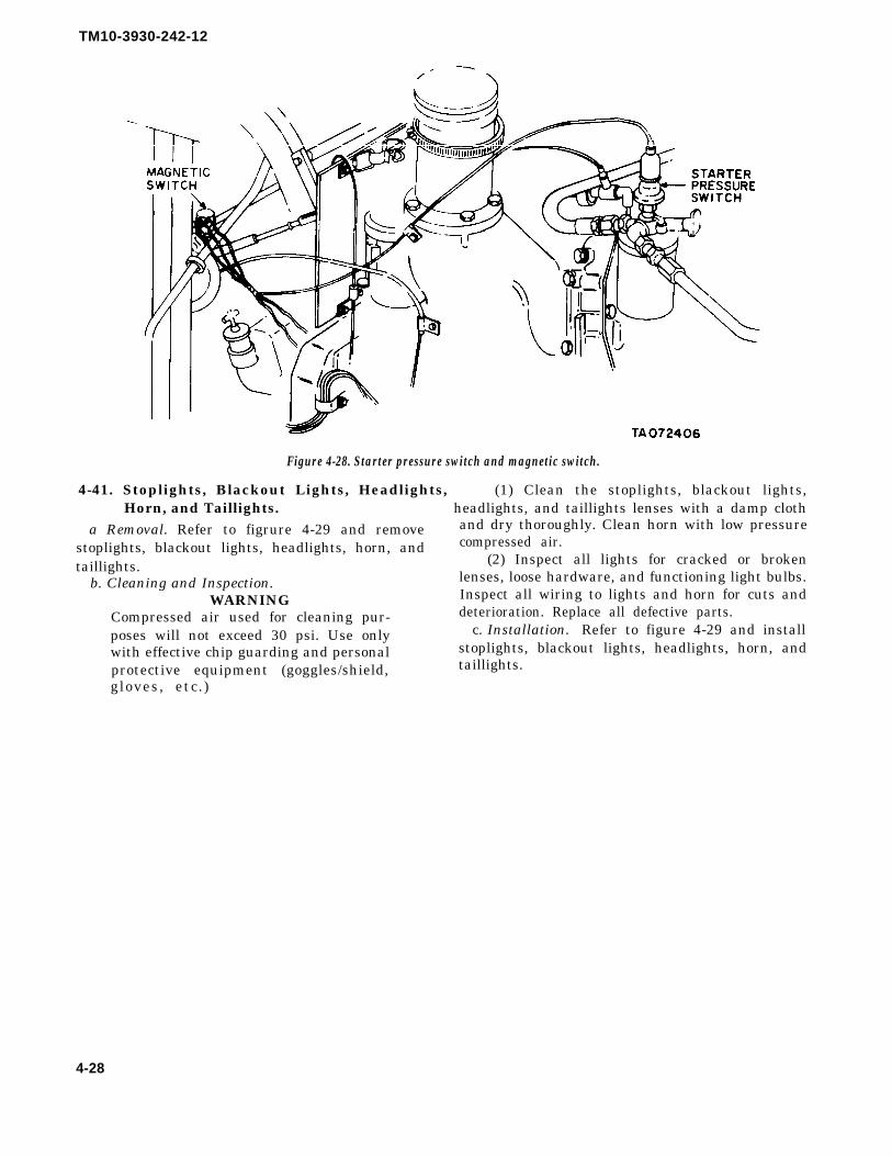
TM10-3930-242-12
Figure 4-28. Starter pressure switch and magnetic switch.
4-41. Stoplights, Blackout Lights, Headlights, (1) Clean the stoplights, blackout lights,Horn, and Taillights. headlights, and taillights lenses with a damp cloth
a Removal. Refer to figrure 4-29 and remove and dry thoroughly. Clean horn with low pressure
stoplights, blackout lights, headlights, horn, andtaillights.
b. Cleaning and Inspection.WARNING
Compressed air used for cleaning pur-poses will not exceed 30 psi. Use onlywith effective chip guarding and personalprotective equipment (goggles/shield,gloves, etc.)
compressed air.(2) Inspect all lights for cracked or broken
lenses, loose hardware, and functioning light bulbs.Inspect all wiring to lights and horn for cuts anddeterioration. Replace all defective parts.
c. Installation. Refer to figure 4-29 and installstoplights, blackout lights, headlights, horn, andtaillights.
4-28

TM10-3930-242-12
Figure 4-29. Stoplights, blackout lights, headlights, horn and taillights, removal and installation.
4-29
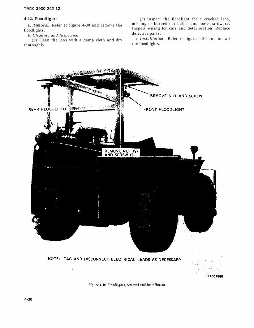
TM10-3930-242-12
4-42. Floodlights (2) Inspect the floodlight for a cracked lens,
a. RemovaL Refer to figure 4-30 and remove the missing or burned out bulbs, and loose hardware.
floodlights. Inspect wiring for cuts and deterioration. Replace
b. Cleaning and Inspection. defective parts.
(1) Clean the lens with a damp cloth and dry c. Installlation. Refer to figure 4-30 and install
thoroughly. the floodlights.
Figure 4-30. Floodlights, removal and installution.
4-30

TM 10-3930-242-12
Section XI. MAINTENANCE OF CONTROLS AND INSTRUMENTS
WARNINGDrycleaning solvent, P-D-680, used toclean parts is potentially dangerous topersonnel and property. Do not use nearopen flame or excessive heat. Flash pointof solvent is 138°F.
4-43. General
This section contains information for organizationalmaintenance of the controls and instruments of theforklift truck.
WARNINGDisconnect battery (+) cable from bat-tery before disconnecting any wiringunder dash.
4-44. Engine Hourmeter
a Removal. Refer to figure 4-31 for location ofhourmeter. Tag and disconnect electrical lead.Remove six nuts, six screws, and three lockwashersattaching hour-meter to instrument panel andremove hourmeter.
b. Inspection and Testing.(1) Inspect the hourmeter for broken glass.
Inspect the electrical wiring for cuts, breaks, anddeterioration.
(2) Connect hourmeter to a 24 volt power sourceand check for proper operation by checking in-dicator above odometer wheels. Indicator shouldrevolve once per minute.
(3) Replace a defective hourmeter.c. Installation. Install hourmeter in instrument
panel using six screws, three lockwashers, and sixnuts. Connect electrical lead.
4-45. Battery and Generator Indicator
a. Removal. Refer to figure 4-31 for location ofbattery and generator indicator. Tag and disconnectelectrical connections. Remove three nuts andIockwashers and remove indicator from instrumentpanel.
b. Testing Test the battery and generator in-dicator by connecting it to an external 24-volt powersource along with another voltmeter of knownaccuracy. Compare the readings of both meters to
d. Installation. Install three mounting nuts andlockwashers to install battery and generator in-dicator in instrument panel.
4-46. Toggle Switches
a. General. The two toggle switches control thefront and rear floodlights. Before removing swit-ches, check operation in ON and OFF positions byobserving operation of the floodlights. Before at-tributing a malfunction to a defective switch, makesure that lamps are not burned out and that elec-trical connections are correct.
b. Removal.(1) Refer to figure 4-31 for location of the front
and rear floodlight toggle switches.(2) Tag and disconnect electrical connections.(3) Remove two locknuts and remove switch
from instrument panel.c. Cleaning and Inspection.
WARNINGCompressed air used for cleaning pur-poses will not exceed 30 psi. Use onlywith effective chip guarding and personalprotective equipment (goggles/shield,gloves, etc.)
(1) Clean toggle switches with an approvedcleaning solvent and dry thoroughly, or use lowpressure compressed air.
(2) Inspect switches for loose connections orbroken hardware. Replace a defective switch.d. Installation. Mount toggle switch on in-strument panel using two locknuts. Reconnectelectrical connections.
4-47. Panel Lights
a. Removal. Refer to figure 4–31 for location ofpanel lights. Disconnect electrical connector andremove two mounting screws to remove panel lightsfrom instrument panel.
b. Inspection. Inspect the panel lights for looseconnections, defective wiring, and missing orburned out light bulbs. Replace defective lights.
c. Installation. Use two screws to mount panellight on instrument panel. Connect electrical con-nector.
determine the accuracy of the indicator. The in-dicator readings should correspond as follows: red
4-48. Starter and Horn Push Button Switches
(lb), 18-22V; yellow, 22-26V; green, 26-30V; and a. Testing. Test for a defective switch by
red(rh), 30-34V. disconnecting leads from switch to horn or starter,
c. Inspection. Inspect the battery and generator and connecting a test light between the switchindicator for broken cover glass and loose electrical terminals. Push the button. If the test light does not
connections. Replace a defective indicator. light, the switch is defective.
4-31

TM10-3930-242-12
b. Removal.(1) Refer to figure 4-31 for location of starter
and horn push button switches.(2) Tag and disconnect electrical connections.(3) Unscrew boot covering push button and
remove switch.c. Inspection. Inspect switches for corrosion,
loose connections, and defective wiring. Replace adefect ive switch .
d. Installation.(1) Screw boot and push button switch into
instrument panel. Refer to figure 4-31 for properlocation.
(2) Connect electrical connections.
4-49. Light Switch
a. General. The light switch controls the panellights, headlights, taillights, marker lights, andblackout head lights and taillights. Operate switchand observe lights for proper operation. Check forburned out light bulbs and correct wiring beforeattributing failure to a defective switch.
b. Removal. Refer to figure 4-31 for location oflight switch. Tag and disconnect electrical con-nections. Remove four screws that mount lightswitch to instrument panel and remove light switch.
c. Inspection. Inspect the light switch for cracks,breaks, loose connections, and defective or missinghardware. Replace a defective switch.
d. Installation. Use four screws to mount lightswitch to instrument panel. Connect electricalconnections.
4-50. Hydraulic Control Levers.
a.Removal. Refer to figure 4-31 and remove thehydraulic control levers.
b. Cleaning and Inspection.(1) Clean the control levers with drycleaning
solvent (item 1, App F) and dry thoroughly.(2) Inspect the hydraulic control levers for
cracks, breaks, and loose hardware. Replace if founddefective.
c. Installation. Refer to figure 4-31 and installthe hydraulic control levers.
4-32

TM10-3930-242-12
NOTE: TAG AND DISCONNECT ELECTRICAL LEADS AND REMOVE MOUNTINGHARDWARE AS NECESSARY.
TA072399
Figure 4-31. Controls and instruments, removal and installation.
4-51. Differential Lockout Control
a. General. The differential lockout control islocated on the firewall of the driver’s compartment.When the lockout pedal is pressed, oil (OE 10) orbrake fluid HBA (MIL-H-13910) is forced to thelockout mechanism, mounted on each differential.This action insures that each pair of driving wheelsturn together.
NOTEBrake fluid HBA (MIL-H-13910) is used
on Athey Model ARTFT-6, S/N RangeF1468 thru F1596 and G1597 thru G1755(NSN 3930-00-419-5744). It is also usedon a limited number of Anthony ModelsMLTG-2, S/N 1098 thru 1159 and 1305thru 1307 (NSN 3930-00-327-1475).
b. Removal. Refer to figure 4-32 and remove thelockout control.
c. Inspection and Service.(1) Inspect the rubber boot and hoses for cuts
4-33
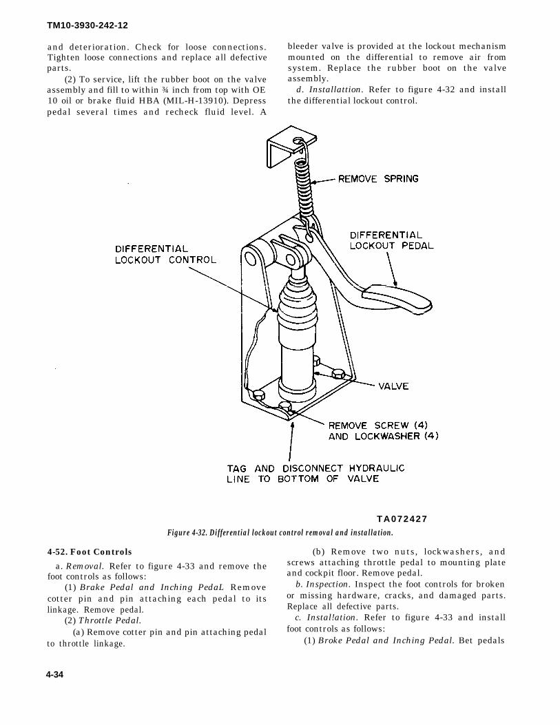
TM10-3930-242-12
and deterioration. Check for loose connections. bleeder valve is provided at the lockout mechanismTighten loose connections and replace all defective mounted on the differential to remove air fromparts. system. Replace the rubber boot on the valve
(2) To service, lift the rubber boot on the valve assembly.assembly and fill to within ¾ inch from top with OE d. Installattion. Refer to figure 4-32 and install10 oil or brake fluid HBA (MIL-H-13910). Depress the differential lockout control.pedal several times and recheck fluid level. A
TA072427Figure 4-32. Differential lockout control removal and installation.
4-52. Foot Controls (b) Remove two nuts, lockwashers, and
a. Removal. Refer to figure 4-33 and remove the screws attaching throttle pedal to mounting plate
foot controls as follows: and cockpit floor. Remove pedal.
(1) Brake Pedal and Inching PedaL Remove b. Inspection. Inspect the foot controls for broken
cotter pin and pin attaching each pedal to its or missing hardware, cracks, and damaged parts.
linkage. Remove pedal. Replace all defective parts.
(2) Throttle Pedal. c. Instal!ation. Refer to figure 4-33 and install
(a) Remove cotter pin and pin attaching pedal foot controls as follows:
to throttle linkage. (1) Broke Pedal and Inching Pedal. Bet pedals
4-34

TM10-3930-242-12
in place and use cotter pin and pinto reconnect themto the correct control linkage.
(2) Throttle Pedal.(a) Use two screws, nuts, and lockwashers to
attach pedal to mounting plate and cockpit floor.(b) Use cotter pin and pin to connect throttle
pedal to the control linkage.
Figure 4-33. Foot Controls, removal and installation.
Section XII . MAINTENANCE OF TRANSMISSION
4-53. General b. Cleaning and Inspection.
This section contains information for organizational (1) Clean the filter head with an approved
maintenance of the transmission. cleaning solvent and dry thoroughly. Make sure oldgasket material is removed, and install a new filter
4-54. Transmission External Filter element and gasket.
a Removal. (2) Inspect the new filter for cracks, breaks, and(1) Remove the forward panel under the right loose connections. Check the oil for contamination.
rear fender. c. Installation.(2) Refer to figure 4-34 and remove the trans- (1) Refer to figure 4-34 and install the trans-
mission external filter. mission external filter.NOTE (2) Service transmission in accordance with
Change filter element at every trans- current lubrication order.mission oil change. The filter element is athrow away type paper element.
4-35
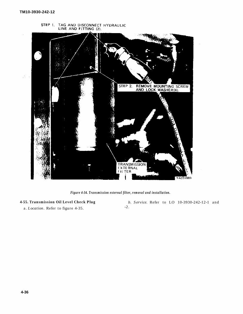
TM10-3930-242-12
Figure 4-34. Transmission external filter, removal and installation.
4-55. Transmission Oil Level Check Plug b. Service. Refer to LO 10-3930-242-12-1 and
a. Location. Refer to figure 4-35. -2.
4-36

TM10-3930-242-12
Figure 4-35. Transmission oil level check plug.
NOTE (1) Range Selector Linkage (low, med, high).Refer to current lubrication order formaintenance instructions for internal oilfilter screen.
4-56. Transmission Linkage
a. Inspect. Check all linkage between operator’scontrols and transmission frequently. Removeconsole panel cover (fig. 4-31) and inspect thelinkage for proper lubrication, cleanliness, wear, anddamage.
Make sure operator’s controls (fig. 2-1) arepositioned to correspond exactly with the detentpositions of range selector valve.
(2) Forward and Reverse Linkage. Make sureoperator’s controls (fig. 2-1) correspond exactlywith valve selector detents.
b. Repair. If (1) or (2) above are out of adjustmentor need repair, report to direct support maintenance.
Section XIII . MAINTENANCE OF PROPELLER SHAFT
WARNING 4-57. Propeller Shaft Yoke FlangeDrycleaning solvent, P-D-680, used to a. Inspection. Inspect propeller shafts and yokeclean parts is potentially dangerous to flange for cracks, breaks, broken welds, or otherpersonnel and property. Do not use near damage.open flame or excessive heat. Flash point b. Service. Service propeller shafts and yokeof solvent is 138°F. flanges in accordance with current lubrication order.
4-37

TM10-3930-242-12
Section XIV. MAINTENANCE OF BRAKES
WARNINGDrycleaning solvent, P-D-680, used toclean parts is potentially dangerous topersonnel and property. Do not use nearopen flame or excessive heat. Flash pointof solvent is 138°F.
4-58. General
This section contains information for organizationalmaintenance of the brakes.
4-59. Service Brakes
a. General. The service brakes are expander tubetype, hydraulically operated. Pressure is suppliedby an engine driven hydraulic pump and applicationis controlled by an applicator valve located underthe operator’s floor plate. The brake adjustment isaccomplished automatically by slack adjusters (fig.4-37) located in the hydraulic lines between theapplicator valve and the wheel brake assemblies.There is no manual adjustment. If a malfunctionoccurs which cannot be corrected by the bleedingprocess, report to direct support maintenance. Donot attempt to repair a slack adjuster, replace it.Lining wear can be detected by observing the arc ofthe brake lining retract springs. Retract springs arevisible on the inboard side of the brake assembly,just below the outer circumference of the backingplate. Flattened springs (with the brakes off) in-dicate need for lining replacement. When the liningis in good condition, the springs will form a shallowarc. Check brake fluid for air after the first shift ofoperation.
b. Straight Hydraulic Brake System BleedingProcedure.
(1) Fill the reservoir with hydraulic oil (OE 10).NOTE
Reservoir must be free of dirt. A screenshould be provided in the reservoir tokeep out foreign particles.
(2) While engine is idling, open each bleedervalve (located on top of automatic slack adj uster fig.4-37) and depress brake pedal until oil flows free ofair. Close the bleed valves.
(3) Apply brakes and hold pedal down for atleast 10 seconds. Repeat this three times, allowing30 seconds between applications.
(4) Release the brakes and open all four bleedervalves. Bleed fluid from the brakes until flow stopsand then close the bleeder valve.
(5) Repeat (3) and (4) above until no air can bedetected escaping from the fluid.
(6) Repeat the entire bleeding procedure if thebrakes show any evidence of dragging oroverheating during the first few hours of operation.
NOTEBrake lines should be checked for air afterthe first shift of operation. If brakes donot release properly after application,replace hydraulic tank filter. A clogged orrestricted filter will prevent the oil fromreturning to the tank and therefore willnot allow the brakes to release.
4-60. Emergency Brake Cable and Lever
a. Removal. Refer to figure 4-36 and remove theemergency brake cable and lever.
b. Cleaning and Inspection.(1) Clean the emergency brake cable and lever
with drycleaning solvent (item 1, App F), and drythoroughly.
(2) Inspect the cable for broken wires and kinks.Inspect emergency brake lever and mountingbrackets for cracks, breaks, and damaged parts.Replace all defective parts.
c. Installation. Refer to figure 4-36 and installemergency brake cable and lever.
d. Adjustment.(1) Release emergency brake.(2) Refer to figure 4-36 and remove yoke pin
and cotter pin.(3) Turn yoke clockwise to tighten brake and
counterclockwise to loosen brake.(4) Replace yoke pin and cotter pin.(5) Minor adjustment is accomplished by
turning the knurled adjusting knob which is locatedat the top of the brake lever. Turn clockwise totighten; counterclockwise to loosen.
4-38

TM10-3930-242-12
4-61. Slack Adjusters and Llnes
a. Removal Refer to figure 4-37 for location ofslack adjusters and remove as follows:
(1) Tag and disconnect two hydraulic lines toeach slack adjuster.
(2) Cap all lines when disconnected to preventforeign material from entering the brake system.
(3) Remove two screws, nuts, and lockwashersattaching each slack adjuster to the main frame.Remove the four slack adjusters.
b. Cleaning and Inspection(1) Clean slack adjuster with an approved
cleaning solvent and dry thoroughly.(2) Inspect for corrosion, cracks, and loose con-
nections. Check hoses for cuts and deterioration.c. Installation. Refer to figure 4-37 and install
the slack adjusters as follows:(1) Use two screws, nuts, and lockwashers to
mount each of the four slack adjusters to the mainframe.
(2) Reconnect two hydraulic lines to each of theslack adjusters.
d. Bleeding. After installation of slack adjustersrefer to paragraph 4-59b and bleed the hydraulicbrake system.
TA072400Figure 4-36. Emergency brake cable and lever, removal
and installation.
4-39

TM10-3930-242-12
Figure 4-37. Slack adjusters and lines, removal and installation.
4-62. Brake Accumulator (figure 4-38) is charged with dry nitrogen at approximately 275a. General. The accumulator is provided to store psi. For access to the accumulator cylinder, remove
energy for a limited number of brake applications. the forward panels under the rear fenders.The accumulator system provides pressure for the b. Inspection. Inspect the accumulator for loosebrake system even when the engine is not operating. or corroded fittings or other damage.The accumulator is provided with a free piston and
4-40

TM10-3930-242-12
Figure 4-38. Brake accumulator.
Section XV. MAINTENANCE OF WHEELS
WARNINGDrycleaning solvent, P-D-680, used toclean parts is potentially dangerous topersonnel and property. Do not use nearopen flame or excessive heat. Flash pointof solvent is 138°F.
4-63. Wheel Flanges, Wheels, and TiresWARNING
Do not remove more than one tire at atime, Serious injury to personnel mayresult if vehicle falls.
a Removal. Refer to figure 4-39 and remove thewheel flanges, wheels, and tires.
b. Cleaning and Inspection.(1) Clean the wheels and flanges with
drycleaning solvent (item 1, App F) and drythoroughly.
(2) Inspect the tires for cuts and deterioration.Check lockring, rim, wheel flanges, wheel, and nutsfor cracks, breaks, and dents. Replace all defectiveparts.
WARNINGInsure lockring is properly seated beforeinflating tire. Serious injury to personnelmay result should lockring snap out ofseat.
c. Installation. Refer to figure 4-39 and installthe wheel flanges, wheels and tires.
Figure 4-39. Tire and wheel assembly.
Change 2 4-41

TM10-3930-242-12
Section XVI. MAINTENANCE OF STEERING SYSTEM
WARNINGDrycleaning solvent, P-D-680, used toclean parts is potentially dangerous topersonnel and property. Do not use nearopen flame or excessive heat. Flash pointof solvent is 138°F.
4-64. General
The steering system is hydraulic. Pressure is sup-plied by two hydraulic pumps mounted on the frontand rear of torque converter housing. Normaloperating pressure is 2,000 psi. Source of oil is themain hydraulic oil supply tank. The four wheelsteering capability is controlled by a system of linkslocated under the driver’s compartment. The modesof steering are controlled by a three positionhydraulic cylinder anchored on the pitman and ac-ting upon the intermediate link. A valve, located inthe link anchored on the rear cross shaft bellcrankand wheel forward end of the intermediate link, con-trols action of the rear wheel steering by hydraulicpressure.
CAUTIONDo not operate forklift truck with cockpitcompartment doors open to prevent in-jury to personnel.
4-65. Tie Rods and Tie Rod Ends
a. Clean the tie rods and tire rod ends (fig. 4-40)with drycleaning solvent (item 1, App F) and Drythoroughly.
b. Inspect the tie rods and tie rod ends for cracks,bends, and breaks. Inspect the pins for proper fit.Inspect nuts for stripped threads and proper fit.Report defective parts to your supervisor im-mediately.
4-66. Hydraulic Steering CylindersNOTE
After removing hydraulic lines, be sureand cap lines and use plug caps on cylin-ders to keep out foreign objects.
a Cleaning. Clean the steering cylinders withdrycleaning solvent (item 1, App F) and drythoroughly.
b. Inspection. Inspect the steering cylinder pinsfor conrrect fit. Check mounting and cylinder forcracks and damage. Check hydraulic lines for bendsand nicks. Check line fittings for leaks and crackednuts. Replace defective parts.
4-67. Drag Link Inspection
Inspect the drag link (fig. 4-41) for binding, breaks,or bends. Check mounting hardware for security.Replace a defective drag link.
TA031876Figure 4-41. Drag link.
Figure 4-40. Tie rods and tie rod ends.
4-42

TM10-3930-242-12
Section XVII . MAINTENANCE OF HOOD AND BODY
4-68. Roll Over Protective Structure (ROPS) b. Inspection. Inspect the ROPS for cracks,breaks, orother damage. Inspect mounting har-a. Removal
(1) Remove floodlight (pare 4-42). dware for wear, cracks, or breaks. Replace defective
(2) Refer to figure 4-42 and remove nine screws parts.
(1) and clips (2) to remove floodlight wire (3) from thec. Installation.
ROPS. (1) Use a suitable hoisitng device to lift the
(3) Remove two screws (4) and lockwashers (5) ROPS (9) into place.
holding bottom of the ROPS to attachment structue (2) Install two lockwashers (5) and screws (4) to
(figure 4-42). pull the ROPS into position in attachment struc-
(4) Attach a hoisting device to lift ROPS. ture.
Remove two nuts (6), bolts (7), and washers (8)(3) Install nine screws (1) and clips (2) and at-
holding the ROPS to vehicle frame. Lift the ROPS tach floodlight wire (3) to the ROPS.
(9) clear of vehicle and remove. (4) Install floodlight (para 4-41).
4-43

TM10-3930-242-12
I
Figure 4-42. Roll overprotective structure (ROPS), removal and installation.
4-44

4-69. Seata Removal.
(1) Refer to figure 4-43 for removal and in-stallation of the seat for Army Models MHE 200and MHE 202 forklift trucks.
(2) Refer to figure 4-44 for removal and in-stallation of the seat for Army Model MHE 222forklift truck.
WARNINGDrycleaning solvent, P-D-680, used toclean parts is potentially dangerous topersonnel and property. Do not use nearopen flame or excessive heat. Flash pointof solvent is 138ºF.
b. Cleaning and Inspection.(1) Clean controls and mounting hardware with
drycleaning solvent (item 1, App F) and drythoroughly.
(2) Inspect mounting hardware for damage.
TM10-3930-242-12
Replace all defective parts.(c) Adjustment for Army Models MHE 200 and
202.(1) Turn handle clockwise to raise the seat and
counterclockwise to lower.(2) To release all pressure on shock absorbers,
push down on release lever. Release lever willautomatically reset.
(3) Turn tension handle clockwise to increasefirmness of ride and counterclockwise to decrease.
(4) To move seat forward or back pull forwardon handle at bottom of seat.
d. Adjustment for Army Model MHE 222.(1) Move the seat adjustment handle inward to
release the lock and move the seat.(2) Move seat to desired position,(3) Release the handle. This will
reposition the locking mechanism.automatically
4-45

TM10-3930-242-12
Figure 4-43. Seat removal adjustment, and installation. (Army models MHE 200 and MHE 202).
4-46

TM10-3930-242-12
Figure 4-44. Seat removal, adjustment, and installation. (Army model MHE 222).
4-70. Counterweight and Pintle Hook. mounting hardware for corrosion, cracks, and
a. Removal. Refer to figure 4-45 and remove thebreaks. Replace defective parts.
counterweight and pintle.c. Installation. Refer to figure 4-45 and install
b. Inspection. Inspect the pintle hook for properthe counterweight and pintle hook.
locking operation, breaks, and cracks. Check all
4-47

TM10-3930-242-12
Figure 4-45. Counterweight and pintle hook, removal and installation.
S e c t i o n X V I I I . M A I N T E N A N C E O F H Y D R A U L I C L I F T , P U M P , A N D T U B I N G
CAUTIONWhen removing any hydraulic hoses andlines, cap all openings to prevent foreignmaterial from entering system, causingserious damage to the system.
NOTELate model rough terrain forklift trucksare equipped with a filter contaminatorindicator. This indicator is mounted onthe top of the reservoir. Its purpose is tosignal when the main hydraulic oil filter isin “by-pass” and is no longer serviceable.
4-71. Hydraulic Oscillator Cylinder
a. Cleaning. Clean the cylinder with drycleaningsolvent (item 1, App F).
b. Inspection. Inspect for cracks, breaks, ex-cessive wear, or loose or missing hardware. Inspectthe hoses for deterioration and cuts. Replace alldefective parts.
1-72. Tilt CylinderInspect the cylinder piston end for wear. Inspectcylinder for cracks or leaks. If defective, report todirect support maintenance.
4-73. Fork Carriage
a. Removal. Refer to figure 4-46 and remove thefork carriage.
b. Cleaning and Inspection.(1) Clean the carriage with drycleaning solvent
(item 1, App F).(2) Inspect the fork carriage for breaks or
cracks in the welding. Inspect pins for wear. Replaceall defective mounting hardware.
c. Installation. Refer to figure 4–46 and installthe fork carriage.
4-48

TM10-3930-242-12
Figure 4-46. Fork carnage, removal and installation.
4-74. Side Shift Roller Chain, Cylinder, b. Cleaning and Inspection.
and Forks (1) Clean the roller chain, cylinder, and forks
a. Removal.with drycleaning solvent (item 1, App F).
(1) Block the cariage on 2 by 4 inch blocks so(2) Inspect the chain for kinks, and broken or
forks can be shifted manually. Loosen hoses slowly,cracked links. Inspect cylinder for leaks. Replace all
allowing pressure to decrease.defective parts.
(2) Refer to figure 4-47 and remove the sidec. Installation. Refer to figure 4-47 and install
shift roller chain, cylinder, and forks.the side shift roller chain, cylinder, and forks.
4-49
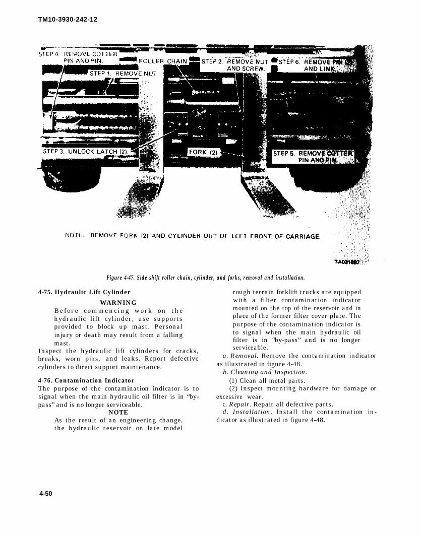
TM10-3930-242-12
Figure 4-47. Side shift roller chain, cylinder, and forks, removal and installation.
4-75. Hydraulic Lift Cylinder
WARNINGBefore commencing work on thehydraulic lift cylinder, use supportsprovided to block up mast. Personalinjury or death may result from a fallingmast.
Inspect the hydraulic lift cylinders for cracks,breaks, worn pins, and leaks. Report defectivecylinders to direct support maintenance.
4-76. Contamination IndicatorThe purpose of the contamination indicator is tosignal when the main hydraulic oil filter is in “by-pass” and is no longer serviceable.
NOTEAs the result of an engineering change,the hydraulic reservoir on late model
rough terrain forklift trucks are equippedwith a filter contamination indicatormounted on the top of the reservoir and inplace of the former filter cover plate. Thepurpose of the contamination indicator isto signal when the main hydraulic oilfilter is in “by-pass” and is no longerserviceable.
a. Removal. Remove the contamination indicatoras illustrated in figure 4-48.
b. Cleaning and Inspection.(1) Clean all metal parts.(2) Inspect mounting hardware for damage or
excessive wear.c. Repair. Repair all defective parts.d. Installation. Install the contamination in-
dicator as illustrated in figure 4-48.
4-50

TM10-3930-242-12
4-77. Hydraulic Hoses
a. General. Hydraulic
Figure 4-48. Contamination indicator.
an inch, such as a -12, indicates 12/16 or 3/4 inch.refer to figure 4-49 for installation of hoses and
truck are equipped with reusable fittings. The hose fittings.is available in bulk and may be cut to length as b. Positioning of Hoses. Make sure that the hoses
required. Higher pressure hose is constructed with a on the hydraulic cylinders, such as the tilt cylinder,
2-wire braid. Hose size is determined by a dash extension cylinder, and lift cylinder, are positioned
number on the hose or fittings. For example, a -12, in such a manner that the hose will not chafe or be
on the hose or fitting indicates size in sixteenths of cut during operation of the unit.
4-51

TM10-3930-242-12
Figure 4-49. Installing high pressure hose fittings.
4-52

TM10-3930-242-12
APPENDIX A
REFERENCES
A-1. Fire Protection and Safety
TB 5-4200-200-100
A-2. Lubrication
LO 10-3930-242-12
A-3. Cleaning
TM 9-247
SB 725-7930-1
A-4. Maintenance
FM 29-2TB 750-651
TM 9-2610-200-24
TM 9-6140-200-14
TM 10-3930-242-20P
DA Pam 738-750
A-5. Shipment and Storage
TM 740-90-1
A-6. Demolition
TM 750-244-3
A-7. Operation
TM 5-331B
Hand Portable Fire Extinguishers Approved for Army Users.
Truck, Lift, Fork, Diesel Engine, Pneumatic Tired Wheels, RoughTerrain; 6,000 lb Capacity, 24 Inch Load Center (Anthony ModelMLT-6), (Army Model MHE 200), (Chrysler Model MLT-6CH),(Army Model MHE 202), (Athey Model ARTFT-6), (ArmyModel MHE 222).
Materials Used for Cleaning, Preserving, Abrading, and CementingOrdnance Materiel and Related Materials Including Chemicals.
Issue of Supplies and Equipment, Engineering Practices of CONUSand Overseas Installation Requirements for Hard and Soft WaterCleaning Compounds.
Organizational Maintenance Operations.Use of Antifreeze Solutions and Cleaning Compounds in Engine
Cooling Systems.Organizational, Direct Support and General Care, Maintenance and
Repair of Pneumatic Tires and Inner Tubes.operator’s, OrganizationaI, Direct Support, and General Support
Maintenance Manual for Lead-Acid Storage Batteries 4HN,24 Volt (6140-059-3528) MS75047-1, 2HN, 12 Volt (6140-00-057-2553) MS35000-1, 6TN, 12 Volt (6140-00-057-2554)MS35000-3.
Organizational Maintenance Repair Parts and Special Tools List:Truck, Lift, Fork, Diesel Engine, Pneumatic Tired Wheels, RoughTerrain; 6,000 lb Capacity, 24 Inch Load Center (Athey ModelARTFT-6, Army Model MHE-222 (FSN 3930-419-5744).
The Army Maintenance Management System (TAMMS).
Administrative Storage of Equipment.
Procedures for Destruction of Equipment to Prevent Enemy Use.
Utilization of Engineer Construction Equipment: Volume B-Lifting,Loading, and Hauling Equipment.
Change 2 A-1/(A-2 blank)


TM 10-3930-242-12
A P P E N D I X B
C O M P O N E N T S O F E N D I T E M L I S T
There are none authorized.
B - 1


TM10-3930-242-12
APPENDIX C
ADDITIONAL AUTHORIZATION LIST
SECTION I. INTRODUCTION
C-1. Scope authorized to you by CTA, MTOE, TDA, or JTA.This appendix lists additional items you are author-ized for the support of the rough terrain fork lift C-3. Explanation of Listing
truck. National stock numbers, descriptions, and quantities
C-2. Generalare provided to help you identify and request the ad-ditional items you require to support this equipment.
This list identifies items that do not have to accom- The items are listed in alphabetical sequence by itempany the rough terrain fork lift truck and that do not name under the type document (i.e., CTA, MTOE,have to be turned in with it. These items are all TDA, or JTA) which authorizes the item to you.
Section II. ADDITIONAL AUTHORIZATION LIST
(1) (2) (3) (4)
National Description QtyStock Number FSCM & Part Number U/M Auth
MTOE AUTHORIZED ITEMS
4910-00-138-1819 Constrictor. bead expander EA 1(31989) TC28
4910-00-204-2644 Gage, tire pressure EA 1(83148) GGG91
Change 2 C-1/(C-2 blank)


TM 10-3930-242-12
APPENDIX D
MAINTENANCE ALLOCATION CHART
Section I. INTRODUCTION
D-1. General
a. This section provides a general explanation ofall maintenance and repair functions authorized atvarious maintenance categories.
b. The Maintenance Allocation Chart (MAC) insection II designates overall authority and responsi-bility for the performance of maintenance func-tions on the identified end item or component.The application of the maintenance functions tothe end item or component will be consistent withthe capacities and capabilities of the designatedmaintenance categories.
c. Section III lists the tools and test equipment(both special tools and common tool sets) requiredfor each maintenance function as referenced fromsection II.
d. Section IV contains supplemental instructionsand explanatory notes for a particular maintenancefunction.D-2. Maintenance Functions. Maintenance func-tions will be limited to and defined as follows:
a. Inspect. To determine the serviceability of anitem by comparing its physical, mechanical, and/orelectrical characteristics with established standardsthrough examination (e.g., by sight, sound, or feel).
b. Test. To verify serviceability by measuringthe mechanical, pneumatic, hydraulic, or electricalcharacteristics of an item and comparing thosecharacteristics with prescribed standards.
c. Service. Operations required periodically tokeep an item in proper operating condition, i.e., toclean (including decontaminate, when required), topreserve, to drain, to paint, or to replenish fuel,lubricants, chemical fluids, or gases.
d. Adjust. To maintain or regulate, within pre+scribed limits, by bringing into proper or exactposition, or by setting the operating characteristicsto specified parameters.
e. Aline. To adjust specified variable elementsof an item to bring about optimum or desiredperformance.
f. Calibrate. To determine and cause correctionsto be made or to be adjusted on instruments ortest, measuring, and diagnostic equipments used inprecision measurement. Consists of comparisonsof two instruments, one of which is a certifiedstandard of known accuracy, to detect and adjustany discrepancy in the accuracy of the instrumentbeing compared.
g. Remove/Install. To remove and install thesame item when required to perform service orother maintenance functions. Install may be theact of emplacing, seating, or fixing into position aspace, repair part, or module (component or as-sembly) in a manner to allow the proper function-ing of an equipment or system.
h. Replace. To remove an unserviceable itemand install a serviceable counterpart in its place.“Replace” is authorized by the MAC and is shownas the third position of the SMR code.
i. Repair. The application of maintenanceservice1, including fault location/troubleshooting2,removal/installation, disassemble/assembly3 proce-dures, and maintenance actions 4 to identifytroubles and restore serviceability to an item bycorrecting specific damage, fault, malfunction, orfailure in a part, subassembly, module (componentor assembly), end item, or system.
j. 0verhaul. That maintenance effort (service/action) prescribed to restore an item to a completelyserviceable/operational condition as required bymaintenance standards in appropriate technicalpublication (i.e., DMWR), Overhaul is normallythe highest degree of maintenance performed bythe Army. Overhaul does not normally return anitem to like-new condition.
1Service-inspect, test, service, adjust, aline, calibrate, and/or replace.2Fault locating/troubleshooting – The process of investigating and detecting the cause of equipment
malfunctioning; the act of isolating a fault within a system or unit under test (UUT).3Diaassembly/assembly – encompasses the step-by-step taking apart (or breakdown) of a spare/func-
tional group coded item to the level of its least componency identified as maintenance significant (i.e.,assigned an SMR code) for the category of maintenance under consideration.
Action –welding, grinding, reiveting, straightening, facing, remachining, and/or resurfacing.
Change 1 D-1

TM10-3930-242-12
k. Rebuild. Consists of those services/actionsnecessary for the restoration of unserviceableequipment to a like-new condition in accordancewith original manufacturing standards. Rebuild isthe highest degree of materiel maintenance appliedto Army equipment. The rebuild operation in-cludes the act of returning to zero those age meas-urements (hours/miles, etc.) considered in classify-ing Army equipment/components.
D-3. Explanation of Columns in the MAC,Section II
a. Column 1, Group Number. Column 1 listsfunctional group code numbers, the purpose ofwhich is to identify maintenance significant com-ponents, assemblies, subassemblies, and moduleswith the next higher assembly, End item groupnumber shall be “00”.
b. Column 2, Component/Assembly. Column 2contains the names of components, assemblies,subassemblies, and modules for which maintenanceis authorized.
c. Column 3, Maintenance Function. Column 3lists the function to be performed on the itemlisted in Column 2. (For detailed explanation ofthese functions, see paragraph D-2).
d. Column 4, Maintenance Category. Column 4specifies, by the listing of a worktime figure in theappropriate subcolumns, the category of mainte-nance authorized to perform the function listed incolumn 3. This figure represents the active timerequired to perform that maintenance function atthe indicated category of maintenance. If thenumber or complexity of the task within the listedmaintenance function vary at different mainte-nance categories, appropriate worktime figures willbe shown for each category. The worktime figurerepresents the average time required to restore anitem (assembly, subassembly, component, module,end item, or system) to a serviceable conditionunder typical field operating conditions. This timeincludes preparation time (including any necessarydisassemble y/assembly time), troubleshooting/faultlocation time, and quality assurance/quality con-trol time in addition to the time required to per-form specific tasks identified for the maintenancefunctions authorized in the maintenance allocation
chart. The symbol designations for the variousmaintenance categories are as follows:
C – Operator or CrewO – organizational MaintenanceF – Direct Support MaintenanceH — General Support MaintenanceD – Depot Maintenance
e. Column 5, Tools and Equipment. Column 5specifies by code, those common tool sets (notindividual tools) and special tools, TMDE, andsupport equipment required to perform the desig-nated function.
f. Column 6, Remarks. This column shall, whenapplicable, contain a letter code, in alphabeticalorder, which shall be keyed to the remarks con-tained in Section IV.
D-4. Explanation of Columns in Tool and TestEquipment Requirements, Section III
a. Column 1, Reference Code. The tool and testequipment reference code correlates with a codeused in the MAC, Section II, Column 5.
b. Column 2, Maintenance Category. The lowestcategory of maintenance authorized to use the toolor test equipment.
c. Column 3, Nomenclature. Name or identifi-cation of the tool or test equipment.
d. Column 4, National Stock Number. The Na-tional stock number of the tool or test equipment.
e. Column 5, Tool Numher. The manufacturer’spart number.
D-5. Explanation of Columns in Remarks,Section IV
a. Column 1, Reference Code. The code record-ed in column 6, Section II.
b. Column 2, Remarks. This column lists infor-mation pertinent to the maintenance function be-ing performed as indicated in the MAC, Section II.
D-2 Change 1

TM 10-3930-242-12
(1)
Groupnumber
01
0100
0101
0102
0103
0101
0105
0106
Section II. MAINTENANCE ALLOCATION CHART
(2)
Component/Assembly
ENGINE
Engine Assembly
Mounts, Engine
Crankcase, Block, CylinderHead
Head Assembly
Crankshaft
Flywheel AssemblyFlywheel
Flywheel Housing
Pistons, Connecting RodsConnecting Rods
Pistons
VaIves, Camshafts, and TimingSystems
Camshaft and Gear Train
Rocker Arm and RelatedParts
Engine Lubrication SystemPump, Oil and Related
PartsElement, Oil Filter
Cooler, Oil
Breather, Crankcase Dipstick, and Filler Pipe
(3)
Maintenancefunction
InspectServiceAdjustReplace
Repair
Overhaul
InspectReplace
InspectReplaceRepairOverhaul
InspectReplaceRepair
InspectReplaceRepairInspectReplace
InspectReplaceRepairReplace
InspectReplaceInspectReplaceRepair
ReplaceRepairServiceReplaceInspectTestReplaceServiceReplace
(4)Maintenance category
C
0.10.5
O
0.21.50.4
0.2
0.2
0.50.5
0.10.1
F
8.0
0.12.0
0.11.52.4
8.02.0
8.0
0.2
0.21.01,0
0.11.00.5
H
2.0
14.5
0.320.0
0,24,04.04,0
20.0
4.03.0
D
0.0
8.0
(5)Toolsandeqpt
1,2,31,2,31,2,35 thru 8
10,125 thru 8
10,125 thru 810,12
3,73,7
3,73,73,5,73,5,7
3,73,.5,73,5,7
2,33,5,7,93,5,7,9
2,3
3,73,5,7,93,5,7,92,3,8
3,73,5,7,93,73,.5,7,93,5,7,9
3,7,93,7,92,32,33,73,73,72,32,3
(6)
Remarks
Change 1 D-3
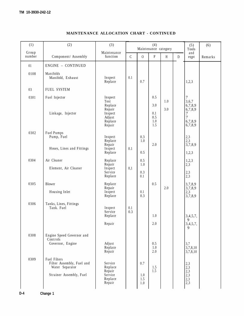
TM 10-3930-242-12
(1)
Groupnumber
01
0108
03
0301
0302
0304
0305
0306
0308
0309
MAINTENANCE ALLOCATION CHART - CONTINUED
(2)
Component/ Assembly
ENGINE – CONTINUED
ManifoldsManifold, Exhaust
FUEL SYSTEM
Fuel Injector
Linkage, Injector
Fuel PumpsPump, Fuel
Hoses, Lines and Fittings
Air Cleaner
Element, Air Cleaner
Blower
Housing Inlet
Tanks, Lines, FittingsTank. Fuel
Engine Speed Governor andControls
Governor, Engine
Fuel FiltersFilter Assembly, Fuel and
Water Separator
Strainer Assembly, Fuel
(3)
Maintenancefunction
InspectReplace
InspectTestReplaceRepairInspectAdjustReplaceRepair
InspectReplaceRepairInspectReplace
ReplaceRepairInspectServiceReplace
ReplaceRepairInspectReplace
InspectServiceReplace
Repair
AdjustReplaceRepair
ServiceReplaceRepairServiceReplaceRepair
(4)Maintenance category
C
0.1
0.1
0,1
0.10.3
O
0.7
0.31.0
0.5
0.51.0
0.30.1
0.10.3
0.7
1.01.51.0
F
0.5
3.0
0.10.51.01.5
2.0
0.5
1.0
2.0
0.51.02.0
1.51.5
H
1.0
3.0
2.0
D
(5)Toolsandeqpt
1,2,3
73,6,76,7,8,96,7,8,9776,7,8,96,7,8,9
2,32,33,7,8,9
1,2,3
1,2,32,3
2,32,3
3,7,8,93,7,8,92,33,7,8,9
3,4,5,7,9
3,4,5,7,9
3,73,7,8,103,7,8,10
2,32,32,32,32,32,3
(6)
Remarks
D-4 Change 1

TM 10-3930-242-12
MAINTENANCE ALLOCATION CHART – CONTINUED
(1)
Groupnumber
03
0309
0311
0312
04
0401
05
0501
0502
0503
0504
0505
(2)
Component/Assembly
FUEL SYSTEM –CONTINUED
Fuel Filters – ContinuedFilter Element, Strainer
Assembly
Engine Starting AidsStarting Aid Assembly
Accelerator, Throttle or ChokeControls
Control, Throttle
EXHAUST SYSTEM
Muffler and Pipes
COOLING SYSTEM
Radiator
Shrouds
Water Manifold, Headers,Thermostats and HousingGasket
Thermostat and Housing
Hoses, Clamps and Fittings
water Pump
Fan AssemblyGuard, FanFan
Pulley Assembly
(3)
Maintenancefunction
Replace
ServiceReplaceRepair
InspectAdjustReplaceRepair
InspectReplace
InspectTestServiceReplace
Repair
Replace
InspectReplaceInspectReplace
InspectReplaceRepair
ReplaceInspectReplaceInspectReplaceRepair
(4)Maintenance category
C
0.1
0.1
0.1
0.2
0.1
O
0.5
0.21.00.5
0.50.50.5
1.0
0.5
0.5
0.10,5
0.3
0.11.0
1.00.10.50.10.51.0
F
1.5
2.0
1.5
H D
(5)Toolsandeqpt
2,3
2,31,2,31,2,3
1,2,31,2,31,2,3
1,2,3
2,3
3,4,5,7,93,4,5,7,9
2,3
33
3
337,10
2,332,3
2,32,3
Change 1
(6)
Remarks
D-5

TM 10-3930-242-12
(1)
Groupnumber
05
0505
06
0601
0602
0603
0607
0608
MAINTENANCE ALLOCATION CHART – CONTINUED
(2)
Component/Assembly
COOLING SYSTEM –CONTINUED
Fan Assembly — ContinuedBelt, Fan Drive andTightener
Linkage, Fan DisconnectControl
ELECTRICAL SYSTEM
Gencrator
Generator Drive Belt andTightener
Generator Regulator
Starting MotorStarter
Relay (MHE-200 w/o ROPS,MHE-202 w/o ROPS,MHE-200 w/ROPS, MHE-202 w/ROPS)
Relay (MHE-222 w/o ROPS,MHE-222 w/ROPS)
Instrumcnt or Ehgine ControlPanel
Panel, Control
Gages, Switches andIndicator Lights
Switch, Rotary
Miscellaneous ItemsSwitches
(3)
Maintenancefunction
InspectAdjustRcplaceInspectAdjustReplaceRepair
InspectTestReplaceRcpairInspectAdjustReplace
InspectTestReplace
InspectTestReplaceRepairReplace
Replace
InspectTestReplaceRepairInspectTestReplaceInspectTestReplaceRepair
Replace
(4)Maintenance category
C
0.1
0.1
0.1
0.1
0.1
O
0.10.50.10.10.50.5
0.10.50.5
0.10.5
0.10.50.5
0.10.50.5
0.5
0.10.50.5
0.10.5
0.10.50.5
0.5
F
2.0
2.00.5
H D
(5)Toolsandeqpt
2,32,332,32,32,3
32,32,33,7,8
2,32,3
32,32,3
32,32,33,7,82,3
2,3
2,31,2,31,2,3
2,31,2,3
2,31,2,31,2,3
1,2,3
(6)
Remarks
D-6 Change 1

TM 10-3930-242-12
MAINTENANCE ALLOCATION CHART – CONTINUED
(1)
Groupnumber
Maintenance category
06
0609
0610
0611
0612
0613
07
0705
0708
0710
0713
(2)
Component/Assembly
ELECTRICAL SYSTEM –CONTINUED
Lights
Sending Units and WarningSwitches
Warning Switches
Horn
Batteries, StorageBatteries, Box, Holddown
and Cables
Connector, Slave Receptacle
Chassis Wiring Harness
Lead, Electrical (MHE-200W/ROPS, MHE-202 w/ROPS, MHE-222 w/ROPS)
TRANSMISSION
Gear Shift ControlsControls, Transmission
Linkage
Torquc Connverter
Hoses, Lines and Fittings
Transmi.ssion Assembly(Hydraulic)
Intermediate Clutch
(3)
Maintenancefunction
InspectTestReplaceRepair
InspectTestReplace
TestReplace
InspectTestServiceReplaceInspectTeatReplaceRepair
InspectTestReplaceRepairReplace
InspectAdjustReplace
TestServiceReplaceOverhaulInspectReplace
TestServiceReplaceRepairOverhaul
TestReplace
(4)
C
0.10.1
0.1
0.1
0.1
0.3
01
0.2
0.1
0.1
O
0.50.5
1.01.0
0.5
0.3
1.0
0.10.50.5
1.0
1.5
0.1
0.5
1.0
0.5
F
1.01.0
0.2
0.2
0.2
8.0
H
1.0
8.0
5.0
D
8.08.0
40.0
(5)Tools
andeqpt
2,32,3
23,7,10
2,3
2,3
2,3
2,32,32,3
2,33,7,103,7,103,7,10
3,7,93,7,9
3,72,33,7,9,12
1,2,3
3,72,33,5,7,935,7,9
2,33,7,9
(6)
Remarks
Change 1 D-7
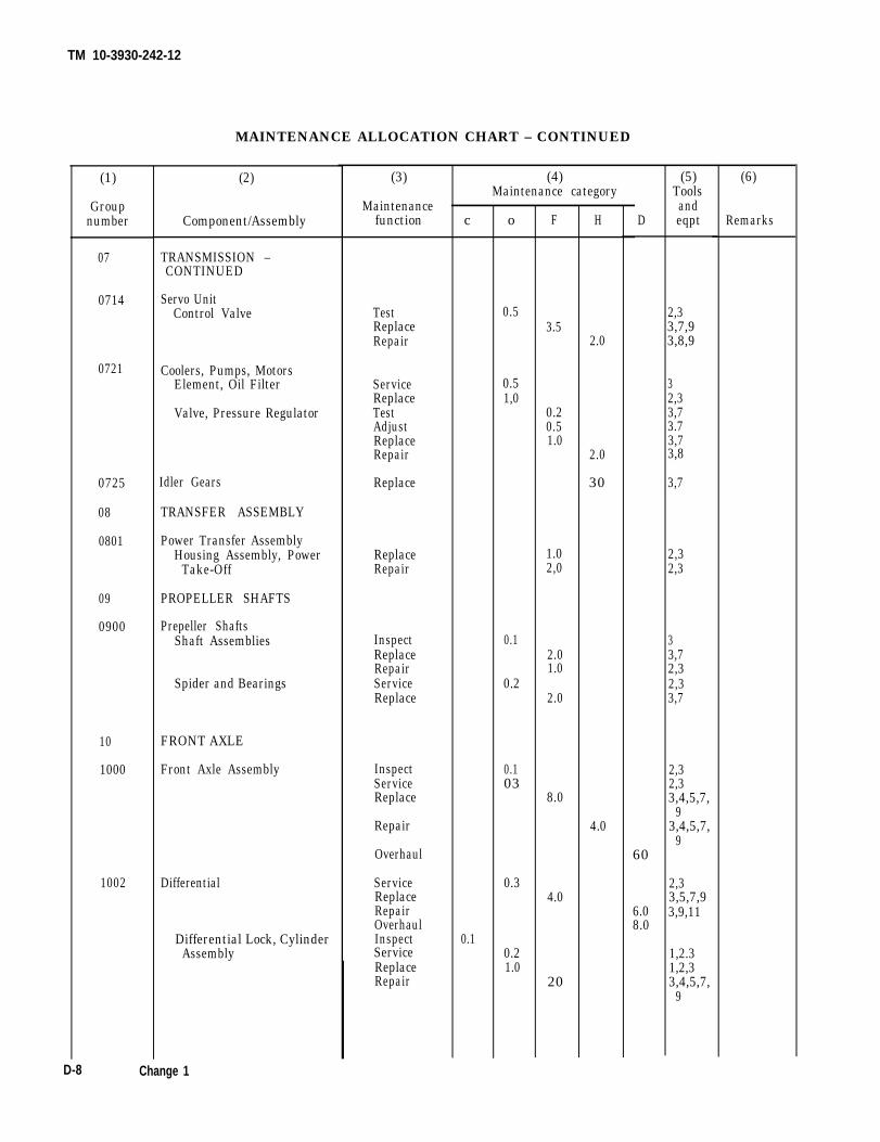
TM 10-3930-242-12
MAINTENANCE ALLOCATION CHART – CONTINUED
(1)
Groupnumber
07
0714
0721
0725
08
0801
09
0900
10
1000
1002
(2)
Component/Assembly
TRANSMISSION –CONTINUED
Servo UnitControl Valve
Coolers, Pumps, MotorsElement, Oil Filter
Valve, Pressure Regulator
TRANSFER ASSEMBLY
Power Transfer AssemblyHousing Assembly, Power
Take-Off
PROPELLER SHAFTS
Prepeller ShaftsShaft Assemblies
Spider and Bearings
FRONT AXLE
Front Axle Assembly
Differential
Differential Lock, CylinderAssembly
D-8 Change 1
(3)
Maintenancefunction
TestReplaceRepair
ServiceReplaceTestAdjustReplaceRepair
Replace
ReplaceRepair
InspectReplaceRepairServiceReplace
InspectServiceReplace
Repair
Overhaul
ServiceReplaceRepairOverhaulInspectServiceReplaceRepair
c
0.1
(4)Maintenance category
o
0.5
0.51,0
0.1
0.2
0.103
0.3
0.21.0
F
3.5
0.20.51.0
1.02,0
2.01.0
2.0
8.0
4.0
20
H
2.0
2.0
30
4.0
(5)Toolsand
D eqpt
2,33,7,93,8,9
32,33,73.73,73,8
3,7
2,32,3
33,72,32,33,7
2,32,33,4,5,7,
93,4,5,7,
960
2,33,5,7,9
6.0 3,9,118.0
1,2.31,2,33,4,5,7,
9
(6)
Remarks
Idler Gears

TM 10-3930-242-12
MAINTENANCE ALLOCATION CHART – CONTINUED
Change 1 D-9

TM10-3930-242-12
MAINTENANCE ALLOCATION CHART - CONTINUED
(1)
Groupnumber
12
1201
1202
1204
1206
13
1311
1313
14
1401
(2)
Component/Assembly
BRAKES
Hand BrakesParking Brake
Hand Brake Lever, Assembly
Hand Brake Link Assembly
Service Brake
Brake Adjusters
Hydraulic Brake SystemValve, Disconnect
Valve, Brake
Accumulator, Brake
Mechanical Brake SystemPedal and Linkage
WHEELS
Wheel AssemblyHub and Drum Assembly
Wheel Assembly
Tires
STEERING
Mechanical Steering GearAssembly
Steering Wheel
Tie Rods and SystemAdjustment
(3)
Maintenancefunction
ReplaceRepairReplaceRepairReplaceRepair
InspectReplaceRepairInspectReplaceRepair
InspectTestReplace
ReplaceRepairInspectServiceReplaceRepair
ReplaceRepair
Replace
InspectServiceReplaceRepair
Inspect
ReplaceRepair
InspectReplaceInspectAdjustReplaceRepair
(4) (5)Maintenance category Tools
C
0.1
0.10.3
0.1
O
0.51.01.01.0
0.1
0.11.0
0.1
0.1
0.11.01.0
1.01.0
0.3
1.01.0
0.1
F
1.52.0
16.0
2.0
0.21.0
1.01.0
1.5
1.01.0
1.01.0
0.5
2.03.00.5
H
1.0
endD eqpt
3,7,93,7,93,7,93,7,93,7,93,7,9
2,33,7,9
3,7,9
33,73,72,33,7,93,7,9
3,1,133,13,1,13
2,32,3
2,32,3
2,33,7,93,7,9
3,7,93,7,9
3,4,62,33,73,7,93,7,9
(6)
Remarks
D-10 Change 1

TM 10-3930-242-12
MAINTENANCE ALLOCATION CHART - CONTINUED
(1)
Groupnumber C
14
1401
1410
1411
1412
1414
15
1501
1502
1503
18
1801
(2)
Component/Assembly
STEERING – CONTINUED
Mechanical Steering GearAssembly – Continued
Steering Gear Assembly
Link, Drag
Hydraulic PumpPump, Rear Steering
Hcsses, Lines, Fittings
Hydraulic CylinderCylinder, Steering
Steering System ValvesValve, Steering
FRAME, TOWING ATTACH-MENTS AND DRAWBARS
Frame Assembly
Roll Over ProtectiveStructure
Counterweights
Pintles and TowingAttachments
Pintle
BODY, CAB, AND HOOD
Body, Cab and Hood AssembliesBody Covers and Panels
Cockpit
(3)
Maintenancefunction
ReplaceRepairInspectReplaceRepair
TestReplace
Repair
InspectReplaceRepair
InspectReplaceRepair
AdjustReplaceRepair
InspectReplaceInspectReplaceRepair
Replace
InspectReplace
InspectReplaceInspectReplaceRepair
(4)Maintenance category
0.1
0.1
0.1
O
0.1
0.50.5
0.2
1.5
0.22.0
0.10.1.0.1
F
1.01.0
0.61.0
0.52.0
2.0
1.01.0
0.52.03.0
3.0
16.04.0
H
2.01.0
D
(5)Toolsandeqpt
2,32,32,33,7,92,3
7,123,7,10,
123,7,10,
12
2,32,3
3,7,103,7,10
3,73,5,7,103,5,7,10
32,3,9
1,5,7,93,5,7,9
2,3
32,3
31,2,331,2,33,4,5,7,9,11
(6)
Remarks
Change 1 D-11

TM 10-3930-242-12
(1)
Groupnumber
18
1801
1802
1805
1806
1808
22
2210
24
2401
2402
2403
MAINTENANCE ALLOCATION CHART - CONTINUED
(2)
Component/Assembly
BODY, CAB, AND HOOD –CONTINUED
Body, Cab and Hood Assem-blies – Continued
Frame Console
Fenders
Floors, Subfloors, and RelatedComponents
Floors
Seals
Stowage Racks, BoxesTool Box
BODY ACCESSORY ITEMS
Data Plates
HYDRAULIC AND FUELSYSTEMS
Pump
Manifold and Control ValvesPump, Engine Driven
Valves, 2 and 3 Spool
Valve, Replenishing
Hydraulic and Manual ControlsControl, Levers and Linkage
D-12 Change 1
(3)
Maintenancefunction
InspectReplaceRepair
Replace
Replace
InspectAdjustReplaceRepair
Replace
Replace
InspectReplace
Repair
TestReplace
Repair
ReplaceRepairReplaceRepair
InspectAdjustReplaceRepair
(4)Maintenance category
C
0.10.1
0.1
O
0.11.01.0
0.5
1.0
0.50.5
0.5
0.5
0.20.50.5
F
0.52.0
2.0
0.52.0
2.0
1.51.51.01.0
H D
(5)Tools
andeqpt
1,2,33,4,5,7,9,11
1,2,3
1,2,3
1,2,31,2,3
2,3
2,3
3,73,7,10,123,7,10,12
7,123,7,10,123,7,10,127,10,127,10,127,10,127,10,12
1,2,31,2,3
(6)
Remarks

TM 10-3930-242-12
MAINTENANCE ALLOCATION CHART – CONTINUED
(1)
Groupnumber
24
2404
2405
2406
2407
2408
(2)
Component/Assembly
HYDRAULIC AND FUELSYSTEMS – CONTINUED
Tilt CylindersCylinder, Hydraulic Tilt
(MHE-200 w/o ROPS,MHE-222 w/o ROPSMHE-200 w/ROPS, MHE-222 w/ROPS)
Cylinder Assembly, Tilt(MHE-202 w/o ROPS,MHE-202 w/ROPS)
Mast ColumnForks, Lifting
Boom AssemblyCarriage Assembly
Cylinder, Hydraulic Lift
Strainers, Filters, Lines andFittings
Hoses, Lines and Fittings
Hydraulic CylindersCylinder, Hydraulic Oscilla-
tion, Side Shift andExtension
Cylinder Assembly, Slave(MHE-200 W/O ROPS,MHE-222 w/o ROPS,MHE-200 w/ROPS, MHE-222 w/ROPS)
Cylinder Assembly, Slave(MHE-202 w/o ROPS,MHE-202 w/ROPS)
Liquid Tanks Or ReservoirsTank, Hydraulic
Filter, Hydraulic
(3)
Maintenancefunction
InspectReplace
Repair
InspectReplace
Repair
InspectAdjustReplaceReplaceInspectReplaceRepairInspectReplaceRepair
InspectReplaceRepair
InspectReplaceRepairInspectReplaceRepair
InspectReplaceRepair
InspectServiceReplaceRepairInspectServiceReplace
(4)Maintenance category
C
0.1
0.1
0.1
0.1
0.1
0.1
0.1
0.1
0.1
O
1.5
0.10.5
0.10.41.5
0.50.5
1.0
0.22.02.00.10.50.5
F
1.5
1.5
1.5
2.0
1.51.5
1.01.5
1.5
1.01.5
H D
(5)Tools
andeqpt
3,5,7,10,12
3,5,7,10,12
3,5,7,10,12
3,5,7,10,12
1,2,31,2,33,4,5,72,31,2,33,5,8,1
3,5,8,13,5,8,1
1,2,31,2,3
3,5,8,13,5,8,1
3,5,7,13,5,7,1
3,5,7,13,5,7,1
2,33,5,73,5,71,2,31,2,31,2,3
(6)
Remarks
Change 1 D-13

TM 10-3930-242-12
Section III. TOOL AND TEST EQUIPMENT REQUIREMENTS
5
(1) (2) (3) (4) (5)Tool or teatequipment Maintenance National Tool
ref code category Nomenclature stock number number
1 0 Shop Equip. Auto Maint: 4910-00-754-0650 SC4910-95CLA72Org Maint. CommonNo. 2SC 4910-95-CL-A72
2 0 Shop Equip. Auto Maint: 4910-00-754-0654 SC4910-95CLA74Org Maint. CommonNo. 1SC 4910-95-CL-A74
3 0 Tool Kit, General Mech- 5180-00-177-7033 SC5180-90-CL-N26anics: AutoSC 5180-90-CL-N26
4 F Shop Equip. Welding: 3470-00-357-7268 SC3470-95CLA08Field MaintSC 3470-95-C1 -A08
F Shop Equip. Machine 3470-00-754-0708 SC3470-95CLA02Shop: Field Maint BasicSC 3470-95-CL-A02
6 F Test Set, Diesel Injector 4910-00-317-8265 5910359
7 F Shop Equip, Auto Maint: 4910-00-754-0705 SC4910-95CLA31Field Maint, BasicSC 4910-95-CL-A31
8 F Shop Equip. Fuel and 4910-00-754-0714 SC4910-95CLAO1Elec. Sys. Engine:Field Maint. BasicSC 4910-95-CL-A01
9 F TooI Kit, Light Machine 5180-00-596-1540 SC5180-90CL-N27RepairSC 5180-90-CL-N26
10 F Tool Kit, Master 5180-00-699-5273 SC5180-90-CL-N05MechanicsSC 5180-90-CL-N05
11 F Tool Kit, Body and 5180-00-754-0643 SC5180-90CLN34Fender RepairSC 5180-90-CL-N34
12 F Gauge, Hydraulic pressure H0278M0 – 3000 PSI
l3 Regulating Kit, Charging 4933-00-856-5593 P/N 8427780 (19205)
Section IV. REMARKS
(1) (2)Reference
code Remarks
Not Applicable
D-14 Change 1

TM10-3930-242-12
A P P E N D I X E
REPAIR PARTS AND SPECIAL TOOLS LIST
There are non authorized.
E-1


TM10-3930-242-12
A P P E N D I X F
EXPENDABLE SUPPLIERS AND MATERIALS LIST
Section I . INTRODUCTION
F-1. Scope
This appendix lists expendable supplies andmaterials you will need to operate and maintain therough terrain forklift truck. These items areauthorized to you by CTA 50-970, ExpendableItems (Except Medical, Class V, Repair Parts, andHeraldic Items).
F-2. Explanation of Columns
a. Column 1—Item number. This number isassigned to the entry in the listing and is referencedin the narrative instructions to identify the material(e.g., “Use drycleaning solvent item 1, App F").
b. Column 2–Level. This column identifies thelowest level of maintenance that requires the listeditem.
C–Operator/CrewO–Organizational Maintenance
c. Column 3—National Stock Number. This is theNational stock number assigned to the item, use itto request or requisition the item.
d. Column 4–Description Indicates the Federalitem name and, if required, a description to identifythe item. The last line for each item indicates thepart number followed by the Federal Supply Codefor Manuafcturer (FSCM) in parentheses, if ap-plicable.
e. Column 5— Unit of Measure (U/M.). Indicatesthe measure used in performing the actual main-tenance function. This measure is expressed by atwo-character alphabetical abbreviation (e.g., ea, in.pr). If the unit of measure differs from the unit ofissue, requestion the lowest unit of issue that willsatisfy your requirements.
S e c t i o n I I . E X P E N D A B L E S U P P L I E S A N D M A T E R I A L S L I S T
(1)Item
Number
123456789
1011121314151617
(2)
Level
C
C
CC
C
(3)National
Stock Number
6850-00-110-44986850-00-274-54216850-00-281-19856850-00-664-56856850-00-285-80116850-00-637-61359150-00-186-66689150-00-191-27729150-00-402-23729150-00-402-44789150-00-491-71979150-00-186-66689150-00-191-27729150-00-065-00299150-00-190-09009150-00-190-09059150-00-190-0907
(4)
Description
Solvent, drycleaning, type II (SD-2) Fed Spec P-D-680
Engine oil, OE/HDO-10Engine oil, OE/HDO-10Engine oil (Arctic)Engine oil (Arctic)Engine oil (Arctic)Gear oilGear oilGreaee, auto and artilleryGreaee, auto and artillery (8143 g)Grease, auto and artillery (8134 g)Greaee, auto and artillery
(5)
U/M
1 pt5 gal6 gal24 qt55 galbulk5 gal55 gal5 gal1 qt55 gal5 gal55 gal2.25 oz4 oz5 lb can35 lb
F-1


TM 10-3930-242-12
Paragraph
AAdministrative storage . . . . . . . . . . . . . . . . . . . .1-3Air cleaner assembly . . . . . . . . . . . . . . . . . . . . . . 4-21Assembly after movement . . . . . . . . . . . . . . . . . 4-4
BBattery . . . . . . . . . . . . . . . . . . . . . . . . . . . . . . . . 3-8Battery and generator indicator . . . . . . . . . . . 4-45Battery holddown cover . . . . . . . . . . . . . . . . . . . . 4-34Brake accumulator . . . . . . . . . . . . . . . . . . . . . . . . 4-62Brake pressure switch . . . . . . . . . . . . . . . . . . . . . 4-39
CContamination indicator . . . . . . . . . . . . . . . . . . . 4-76Controls and instrument, operator
and crew . . . . . . . . . . . . . . . . . . . . . . . . . . . . . . 2-2Controls and instrument, organiza-
tional . . . . . . . . . . . . . . . . . . . . . . . . . . . . . . . . . 4-43Coolant hoses and fittings, oper-
ator and crew . . . . . . . . . . . . . . . . . . . . . . . . . . .3-10Coolant hoses and fittings, organ-
izational . . . . . . . . . . . . . . . . . . . . . . . . . . . . . . .4-26Counterweight and pintle . . . . . . . . . . . . . . . . . . 4-70Crankcase breather . . . . . . . . . . . . . . . . . . . . . . . 4-13
DDescription . . . . . . . . . . . . . . . . . . . . . . . . . . . . . .1-6Destruction of Army materiel to
prevent enemy use . . . . . . . . . . . . . . . . . . . . . .1-4Detailed lubrication information. . . . . . . . . . . . .3-2Differences among models . . . . . . . . . . . . . . . . . .1-8Differential lockout control . . . . . . . . . . . . . . . . . 4-51Dismantling for movement . . . . . . . . . . . . . . . . 4-3Dragline . . . . . . . . . . . . . . . . . . . . . . . . . . . . . . . . 4-67Drive belts . . . . . . . . . . . . . . . . . . . . . . . . . . . . . . 4-28
EEmergency brake cable and lever. . . . . . . . . . . . 4-60Engine air cleaner inspection . . . . . . . . . . . . . . . 3-6Engine air cleaner . . . . . . . . . . . . . . . . . . . . . . . . . 4-20Engine generator . . . . . . . . . . . . . . . . . . . . . . . . . 4-33Engine oil filler pipe and ca p... . . . . . . . . . . . . . 4-15Ether primer . . . . . . . . . . . . . . . . . . . . . . . . . . . . .3-7Exhaust manifold inspection.. . . . . . . . . . . . . . .3-11Exhaust manifold and flange.. . . . . . . . . . . . . . . 4-17Exhaust pipe inspection . . . . . . . . . . . . . . . . . . . 3-12Exhaust pipe and muffler . . . . . . . . . . . . . . . . . . 4-17
FFan belt tension control . . . . . . . . . . . . . . . . . . . . 4-31Fan blade . . . . . . . . . . . . . . . . . . . . . . . . . . . . . . . 4-29Vanguard . . . . . . . . . . . . . . . . . . . . . . . . . . . . . . . 4-27Fan pulley inspection . . . . . . . . . . . . . . . . . . . . . . 4-30Floodlight . . . . . . . . . . . . . . . . . . . . . . . . . . . . . . 4-42Foot controls . . . . . . . . . . . . . . . . . . . . . . . . . . . . 4-52Fork carriage . . . . . . . . . . . . . . . . . . . . . . . . . . . . 4-73Fuel filters . . . . . . . . . . . . . . . . . . . . . . . . . . . . . . . 4-22Fuel pump . . . . . . . . . . . . . . . . . . . . . . . . . . . . . . . 4-19Fuel tank . . . . . . . . . . . . . . . . . . . . . . . . . . . . . . . .3-9
GGeneral
Auxiliary equipment operation . . . . . . . . . . . 2-6Brake . . . . . . . . . . . . . . . . . . . . . . . . . . . . . . . . 4-58Controls and instruments . . . . . . . . . . . . . . . . . 4-43Cooling system . . . . . . . . . . . . . . . . . . . . . . . . . 4-23Electrical system . . . . . . . . . . . . . . . . . . . . . . . 4-32Exhaust system . . . . . . . . . . . . . . . . . . . . . . . . 4-16Fuel system . . . . . . . . . . . . . . . . . . . . . . . . . . . . 4-18
I N D E X
Page
1-14-114-1
3-104-314-234-404-27
4-50
2-1
4-31
3-11
4-174-47
4-7
1-1
1-13-11-2
4-334-1
4-424-18
4-383-104-9
4-214-7
3-103-114-8
3-114-8
4-204-204-174-204-304-344-484-124-9
3-11
2-124-384-314-144-214-94-9
Paragraph
Lubrication information . . . . . . . . . . . . . . . . . . 3-1Lubrication system . . . . . . . . . . . . . . . . . . . . . . 4-11Operation . . . . . . . . . . . . . . . . . . . . . . . . . . . . . . 2-1Operator and crew preventive
maintenance checks and ser-vices (PMCS) . . . . . . . . . . . . . . . . . . . . . . . . .3-3
Organizational preventive main-tenance checks and services (PMCS). . . . . 4-7
Steering system . . . . . . . . . . . . . . . . . . . . . . . . 4-64Transmission . . . . . . . . . . . . . . . . . . . . . . . . . . . 4-53Troubleshooting, operator and crew . . . . . . . .3-5Troubleshooting, organizational . . . . . . . . . . . . 4-9
Generator indicator . . . . . . . . . . . . . . . . . . . . . . . 4-45H
Horn and lights . . . . . . . . . . . . . . . . . . . . . . . . . . . 4-41Horn pushbutton . . . . . . . . . . . . . . . . . . . . . . . . . 4-48Hourmeter, engine . . . . . . . . . . . . . . . . . . . . . . . . 4-44Hydraulic control levers . . . . . . . . . . . . . . . . . . . 4-50Hydraulic hoses . . . . . . . . . . . . . . . . . . . . . . . . . . 4-77
IInspecting new equipment . . . . . . . . . . . . . . . . . .4-1
LLift cylinder, hydraulic . . . . . . . . . . . . . . . . . . . . 4-75Lights . . . . . . . . . . . . . . . . . . . . . . . . . . . . . . . . . . 3-13Light switch . . . . . . . . . . . . . . . . . . . . . . . . . . . . . 4-49Lights and horn . . . . . . . . . . . . . . . . . . . . . . . . . . 4-41Limitations, organizational,
troubleshooting . . . . . . . . . . . . . . . . . . . . . . . . . . 4-10M
Maintenance forms and records . . . . . . . . . . . . .1-2Muffler and exhaust pipe . . . . . . . . . . . . . . . . . . . 4-17Muffler inspection . . . . . . . . . . . . . . . . . . . . . . . . 3-12
NNeutral start switch . . . . . . . . . . . . . . . . . . . . . . . 4-38New euipment inepection . . . . . . . . . . . . . . . . . . .4-1
OOil fiier pipeand cap . . . . . . . . . . . . . . . . . . . . . . 4-15Oil level dipstick . . . . . . . . . . . . . . . . . . . . . . . . . . 4-14Oil filter . . . . . . . . . . . . . . . . . . . . . . . . . . . . . . . . . 4-12Operation of the forklift truck. . . . . . . . . . . . . . .2-4Operation:
In extreme cold . . . . . . . . . . . . . . . . . . . . . . . . .2-6At high altitudes . . . . . . . . . . . . . . . . . . . . . . . . 2-12In extreme heat . . . . . . . . . . . . . . . . . . . . . . . . .2-8In dusty or sandy area . . . . . . . . . . . . . . . . . . . . 2-9In salt water area . . . . . . . . . . . . . . . . . . . . . . . 2-10In snow . . . . . . . . . . . . . . . . . . . . . . . . . . . . . . . 2-13Under rainy or humid condi-
tions . . . . . . . . . . . . . . . . . . . . . . . . . . . . . . . 2-11Organizational preventive mainten-
ance checks and services table. . . . . . . . . . . . .4-8Oscillator cylinder, hydraulic . . . . . . . . . . . . . . . 4-71
PPanel lights . . . . . . . . . . . . . . . . . . . . . . . . . . . . . . 4-47Pintle hook . . . . . . . . . . . . . . . . . . . . . . . . . . . . . . 4-70Preparation for movement . . . . . . . . . . . . . . . . . 4-3Preventive maintenance checks and
services operator/crew . . . . . . . . . . . . . . . . . . .3-4Preventive maintenance checks and
services organizational . . . . . . . . . . . . . . . . . . 4-8Propeller shaft . . . . . . . . . . . . . . . . . . . . . . . . . . . 4-57Propeller shaft yoke flange. . . . . . . . . . . . . . . . . 4-57Pulley and hub . . . . . . . . . . . . . . . . . . . . . . . . . . . 4-30
Page
3-14-52-1
3-6
4-24-424-353-84-4
4-31
4-284-314-314-324-51
4-1
4-503-114-324-28
4-4
1-14-8
3-11
4-254-1
4-74-74-52-4
2-122-132-122-132-132-13
2-13
4-24-48
4-314-47
4-1
3-6
4-24-374-374-20
I-1

TM 10-3930-242-12
Paragraph
RReceptacle slave connector . . . . . . . . . . . . . . . . . 4-35Repair parts . . . . . . . . . . . . . . . . . . . . . . . . . . . . . 4-6Reporting equipment improvement
recommendations (EAR) . . . . . . . . . . . . . . . . . . 1-5Roll over protective structure
(RAPS) . . . . . . . . . . . . . . . . . . . . . . . . . . . . . . . . 4-68S
Scope. . . . . . . . . . . . . . . . . . . . . . . . . . . . . . . . . . . 1-1Seat . . . . . . . . . . . . . . . . . . . . . . . . . . . . . . . . . . . . 4-69Servicing equipment . . . . . . . . . . . . . . . . . . . . . . 4-2Service brakes . . . . . . . . . . . . . . . . . . . . . . . . . . . 4-69Side shift roller chain, cylinder,
and forks . . . . . . . . . . . . . . . . . . . . . . . . . . . . . 4-74Slack adjusters and lines . . . . . . . . . . . . . . . . . . . 4-61Slave connector, receptacle . . . . . . . . . . . . . . . . . 4-36Starter pressure switch and mag-
netic switch . . . . . . . . . . . . . . . . . . . . . . . . . . . 4-40Starter . . . . . . . . . . . . . . . . . . . . . . . . . . . . . . . . . . 4-37Starter and horn pushbutton
switched . . . . . . . . . . . . . . . . . . . . . . . . . . . . . . . 4-48
Page
4-234-2
1-1
4-43
1-14-454-1
4-38
4-494-394-23
4-274-24
4-31
Paragraph
Starting. . . . . . . . . . . . . . . . . . . . . . . . . . . . . . . .2-3Starting aid . . . . . . . . . . . . . . . . . . . . . . . . . . . . . .2-7Steering cylinder, hydraulic . . . . . . . . . . . . . . . . 4-66flopping . . . . . . . . . . . . . . . . . . . . . . . . . . . . . . . . 2-5
TTabulated data . . . . . . . . . . . . . . . . . . . . . . . . . . . 1-7Termostat housing and thermostat . . . . . . . . . . 4-24Tie rods and tie rod ends . . . . . . . . . . . . . . . . . . . 4-65Tilt cylinder . . . . . . . . . . . . . . . . . . . . . . . . . . . . . . 4-72Tools and equipment . . . . . . . . . . . . . . . . . . . . . 4-5Toggle switches . . . . . . . . . . . . . . . . . . . . . . . . . . 4-46Transmission ex ternal filter . . . . . . . . . . . . . . . . 4-54Transmission linkage . . . . . . . . . . . . . . . . . . . . . . 4-56Tranmission oil level check plug.. . . . . . . . . . . . 4-55Troubleshooting . . . . . . . . . . . . . . . . . . . . . . . . . 4-9
VVoltage regulator . . . . . . . . . . . . . . . . . . . . . . . . . 4-36
WWater pump . . . . . . . . . . . . . . . . . . . . . . . . . . . . . 4-25Water pump and pulley . . . . . . . . . . . . . . . . . . . 4-25Wheel flanges, wheels, and tires . . . . . . . . . . . . . 4-63
Page
2-32-12 4-422-11
1-14-154-42 4-484-2
4-314-354-374-364-4
4-24
4-15 4-154-41
1-2

By Order of the Secretary of the Army:
Official:J. C. PENNINGTON
Major General United states ArmyThe Adjutant General
TM 10-3930-242-12
E. C. MEYERGeneral, United States Army
Chief of Staff
* U.S. GOVERNMENT PRINTING OFFICE: 1995-391-862/30147


PIN: 027713-000

This fine document...
Was brought to you by me:
Liberated Manuals -- free army and government manuals
Why do I do it? I am tired of sleazy CD-ROM sellers, who take publicly available information, slap “watermarks” and other junk on it, and sell it. Those masters of search engine manipulation make sure that their sites that sell free information, come up first in search engines. They did not create it... They did not even scan it... Why should they get your money? Why are not letting you give those free manuals to your friends?
I am setting this document FREE. This document was made by the US Government and is NOT protected by Copyright. Feel free to share, republish, sell and so on.
I am not asking you for donations, fees or handouts. If you can, please provide a link to liberatedmanuals.com, so that free manuals come up first in search engines:
<A HREF=http://www.liberatedmanuals.com/>Free Military and Government Manuals</A>
– SincerelyIgor Chudovhttp://igor.chudov.com/
– Chicago Machinery Movers