Embed Size (px)
Citation preview
TM 10-3930-618-10TECHNICAL MANUAL
OPERATOR’S MANUALTRUCK, LIFT, FORK;
GASOLINE ENGINE DRIVEN;PNEUMATIC TIRED WHEELS;
6000-LB CAPACITY;168-INCH LIFT;
ALLIS-CHALMERSMODEL FP60-24PS;
ARMY MODEL MHE-213,FSN 3930-935-7919
HEADQUARTERS. DEPARTMENT OF THE ARMYNOVEMBER 1971
This copy is a reprint which includes currentpages from Changes 3 and 4.
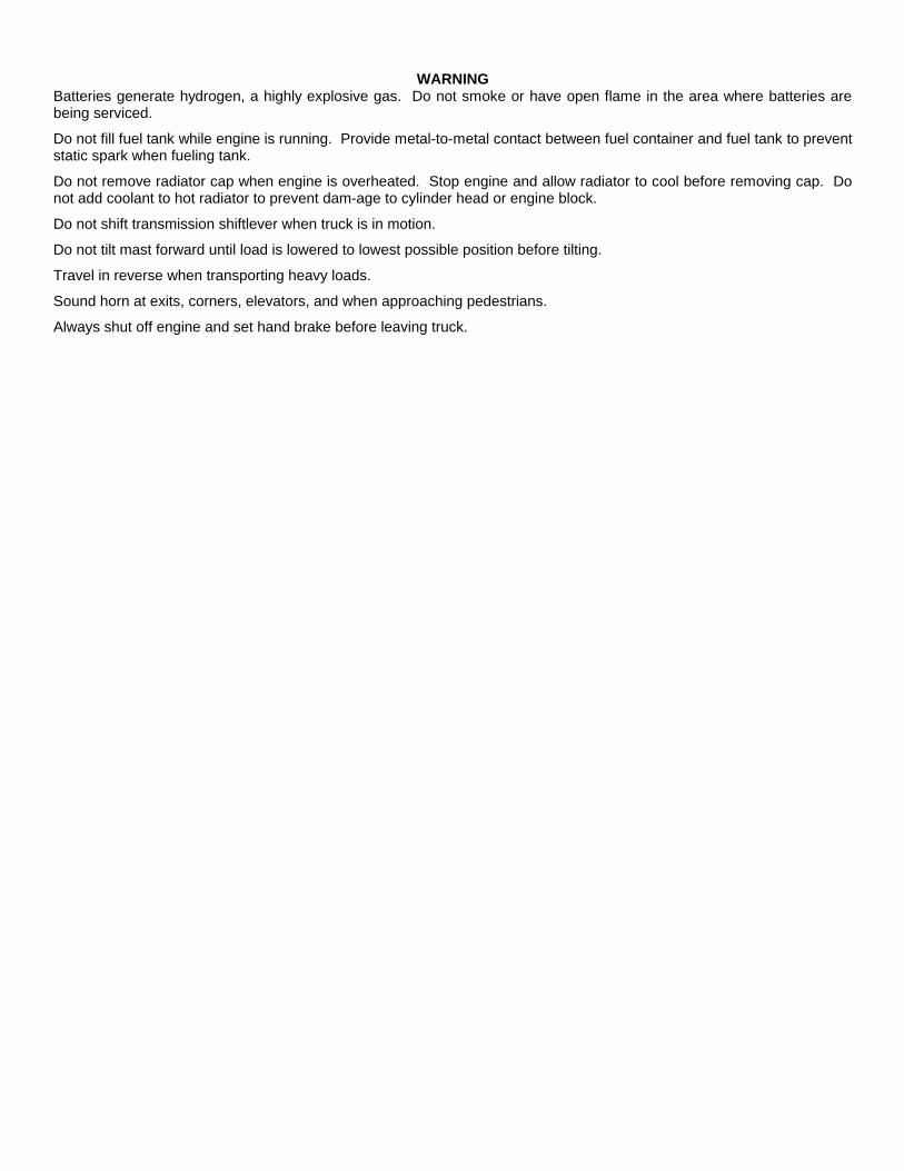
WARNINGBatteries generate hydrogen, a highly explosive gas. Do not smoke or have open flame in the area where batteries arebeing serviced.
Do not fill fuel tank while engine is running. Provide metal-to-metal contact between fuel container and fuel tank to preventstatic spark when fueling tank.
Do not remove radiator cap when engine is overheated. Stop engine and allow radiator to cool before removing cap. Donot add coolant to hot radiator to prevent dam-age to cylinder head or engine block.
Do not shift transmission shiftlever when truck is in motion.
Do not tilt mast forward until load is lowered to lowest possible position before tilting.
Travel in reverse when transporting heavy loads.
Sound horn at exits, corners, elevators, and when approaching pedestrians.
Always shut off engine and set hand brake before leaving truck.
Change In force: C3 and C4TM 10-3930-618-10
C4
CHANGE HEADQUARTERSDEPARTMENT OF THE ARMY
NO. 4 Washington D.C., 30 September 1991
OPERATOR’S MANUALTRUCK, LIFT, FORK: GASOLINE ENGINEDRIVEN; PNEUMATIC TIRED WHEELS;6000-LB. CAPACITY; 168-INCH LIFT;
ALLIS-CHALMERS MODELFP60-24PS; ARMY MODEL MHE-213,
NSN 3930-00-935-7979
TM 10-3930-618-10, 22 November 1971, is changed as follows:page 1-1, the following paragraph is added after Section II. "DESCRIPTION AND DATA:"
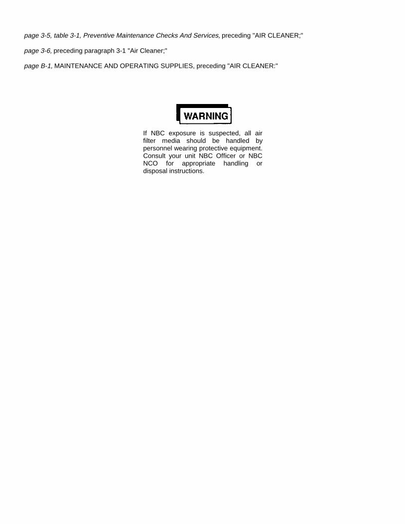
page 3-5, table 3-1, Preventive Maintenance Checks And Services, preceding "AIR CLEANER;"
page 3-6, preceding paragraph 3-1 "Air Cleaner;"
page B-1, MAINTENANCE AND OPERATING SUPPLIES, preceding "AIR CLEANER:"
If NBC exposure is suspected, all airfilter media should be handled bypersonnel wearing protective equipment.Consult your unit NBC Officer or NBCNCO for appropriate handling ordisposal instructions.
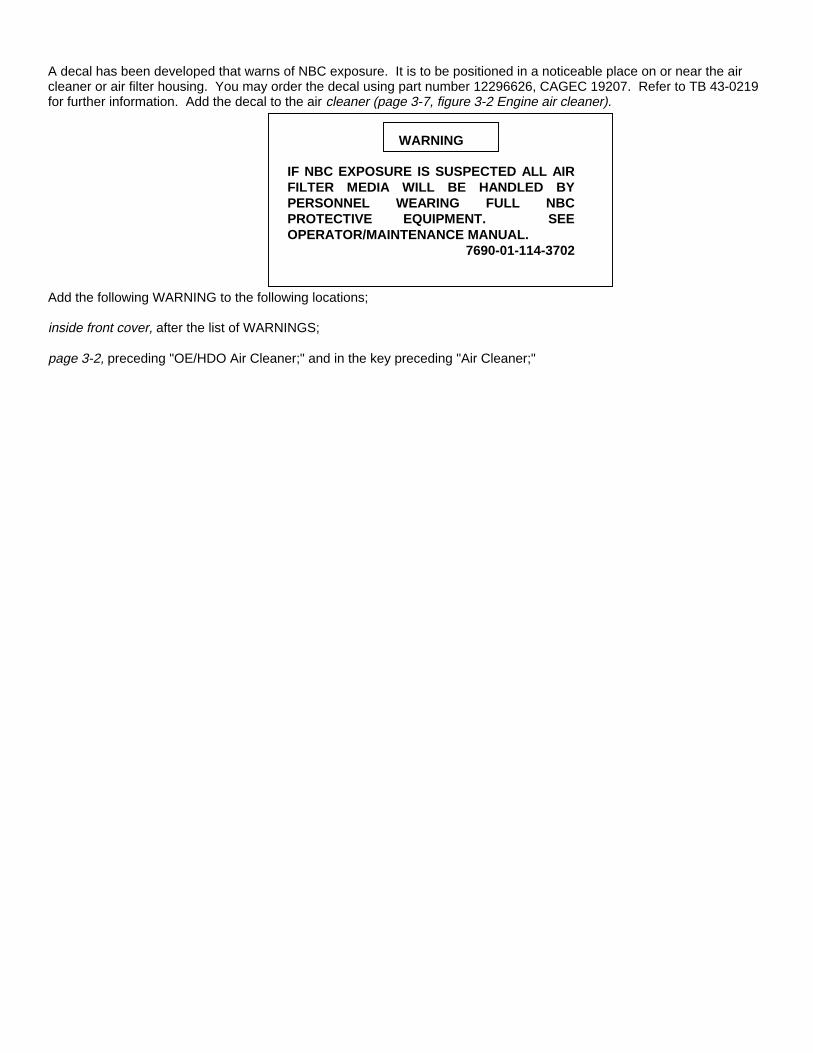
A decal has been developed that warns of NBC exposure. It is to be positioned in a noticeable place on or near the aircleaner or air filter housing. You may order the decal using part number 12296626, CAGEC 19207. Refer to TB 43-0219for further information. Add the decal to the air cleaner (page 3-7, figure 3-2 Engine air cleaner).
WARNING
IF NBC EXPOSURE IS SUSPECTED ALL AIRFILTER MEDIA WILL BE HANDLED BYPERSONNEL WEARING FULL NBCPROTECTIVE EQUIPMENT. SEEOPERATOR/MAINTENANCE MANUAL.
7690-01-114-3702
Add the following WARNING to the following locations;
inside front cover, after the list of WARNINGS;
page 3-2, preceding "OE/HDO Air Cleaner;" and in the key preceding "Air Cleaner;"
By Order of the Secretary of the Army:
GORDON R. SULLIVANGeneral, United States Army
Chief of StaffOfficial:
PATRICIA P. HICKERSONBrigadier General, United States Army
The Adjutant General
Distribution:To be distributed in accordance with DA Form 25-E, block 2212 Operator maintenance requirements for TM 10-3930418-10.
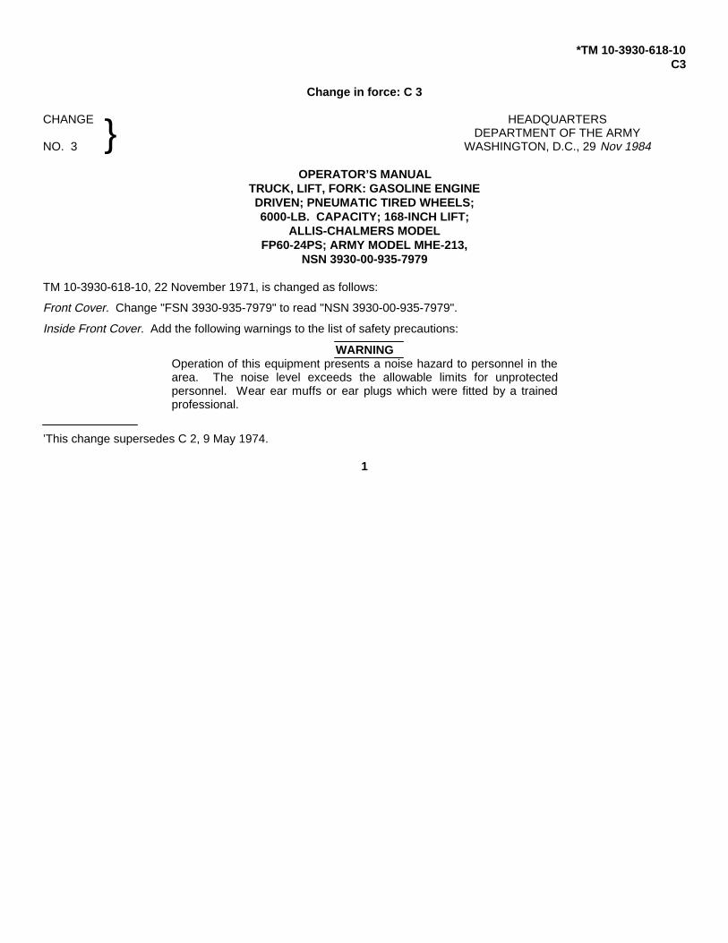
*TM 10-3930-618-10C3
Change in force: C 3
CHANGE HEADQUARTERSDEPARTMENT OF THE ARMY
NO. 3 WASHINGTON, D.C., 29 Nov 1984
OPERATOR’S MANUALTRUCK, LIFT, FORK: GASOLINE ENGINEDRIVEN; PNEUMATIC TIRED WHEELS;6000-LB. CAPACITY; 168-INCH LIFT;
ALLIS-CHALMERS MODELFP60-24PS; ARMY MODEL MHE-213,
NSN 3930-00-935-7979
TM 10-3930-618-10, 22 November 1971, is changed as follows:
Front Cover. Change "FSN 3930-935-7979" to read "NSN 3930-00-935-7979".
Inside Front Cover. Add the following warnings to the list of safety precautions:
WARNINGOperation of this equipment presents a noise hazard to personnel in thearea. The noise level exceeds the allowable limits for unprotectedpersonnel. Wear ear muffs or ear plugs which were fitted by a trainedprofessional.
’This change supersedes C 2, 9 May 1974.
1
}
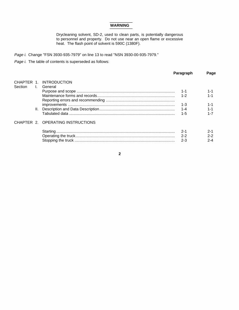
WARNING
Drycleaning solvent, SD-2, used to clean parts, is potentially dangerousto personnel and property. Do not use near an open flame or excessiveheat. The flash point of solvent is 590C (1380F).
Page i. Change "FSN 3930-935-7979" on line 13 to read "NSN 3930-00-935-7979."
Page i. The table of contents is superseded as follows:
Paragraph Page
CHAPTER 1. INTRODUCTIONSection I. General
Purpose and scope ........................................................................................... 1-1 1-1Maintenance forms and records........................................................................ 1-2 1-1Reporting errors and recommending ................................................................improvements ................................................................................................... 1-3 1-1
II. Description and Data Description...................................................................... 1-4 1-1Tabulated data .................................................................................................. 1-5 1-7
CHAPTER 2. OPERATING INSTRUCTIONS
Starting .............................................................................................................. 2-1 2-1Operating the truck............................................................................................ 2-2 2-2Stopping the truck ............................................................................................. 2-3 2-4
2
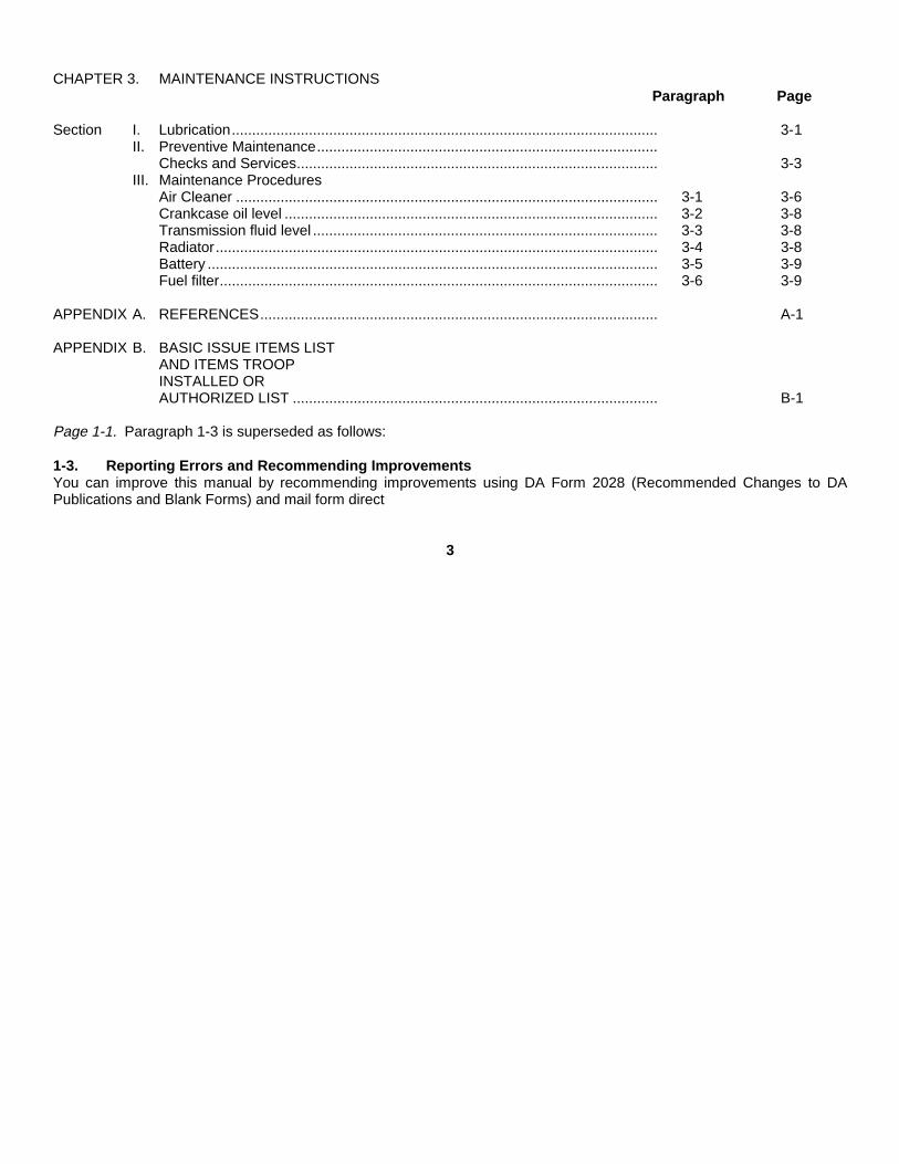
CHAPTER 3. MAINTENANCE INSTRUCTIONSParagraph Page
Section I. Lubrication......................................................................................................... 3-1II. Preventive Maintenance....................................................................................
Checks and Services......................................................................................... 3-3III. Maintenance Procedures
Air Cleaner ........................................................................................................ 3-1 3-6Crankcase oil level ............................................................................................ 3-2 3-8Transmission fluid level ..................................................................................... 3-3 3-8Radiator............................................................................................................. 3-4 3-8Battery ............................................................................................................... 3-5 3-9Fuel filter............................................................................................................ 3-6 3-9
APPENDIX A. REFERENCES.................................................................................................. A-1
APPENDIX B. BASIC ISSUE ITEMS LISTAND ITEMS TROOPINSTALLED ORAUTHORIZED LIST .......................................................................................... B-1
Page 1-1. Paragraph 1-3 is superseded as follows:
1-3. Reporting Errors and Recommending ImprovementsYou can improve this manual by recommending improvements using DA Form 2028 (Recommended Changes to DAPublications and Blank Forms) and mail form direct
3
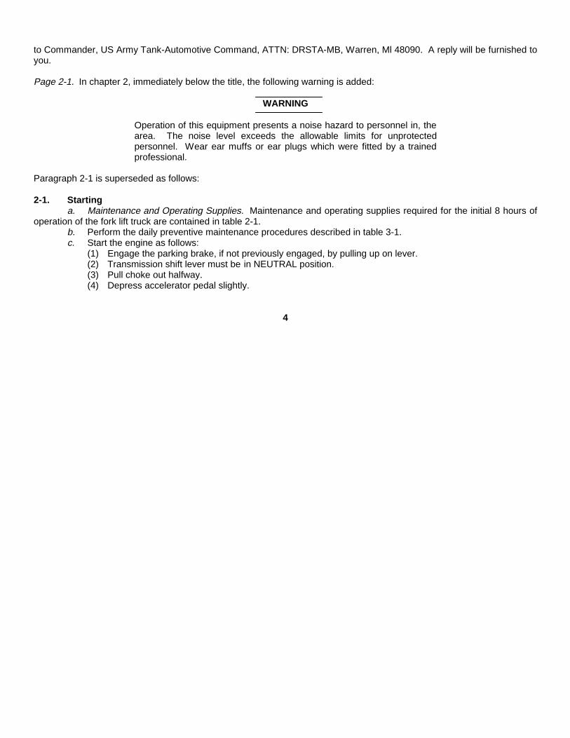
to Commander, US Army Tank-Automotive Command, ATTN: DRSTA-MB, Warren, Ml 48090. A reply will be furnished toyou.
Page 2-1. In chapter 2, immediately below the title, the following warning is added:
WARNING
Operation of this equipment presents a noise hazard to personnel in, thearea. The noise level exceeds the allowable limits for unprotectedpersonnel. Wear ear muffs or ear plugs which were fitted by a trainedprofessional.
Paragraph 2-1 is superseded as follows:
2-1. Startinga. Maintenance and Operating Supplies. Maintenance and operating supplies required for the initial 8 hours of
operation of the fork lift truck are contained in table 2-1.b. Perform the daily preventive maintenance procedures described in table 3-1.c. Start the engine as follows:
(1) Engage the parking brake, if not previously engaged, by pulling up on lever.(2) Transmission shift lever must be in NEUTRAL position.(3) Pull choke out halfway.(4) Depress accelerator pedal slightly.
4
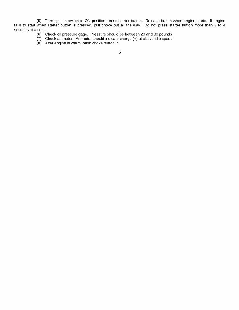
(5) Turn ignition switch to ON position; press starter button. Release button when engine starts. If enginefails to start when starter button is pressed, pull choke out all the way. Do not press starter button more than 3 to 4seconds at a time.
(6) Check oil pressure gage. Pressure should be between 20 and 30 pounds(7) Check ammeter. Ammeter should indicate charge (+) at above idle speed.(8) After engine is warm, push choke button in.
5
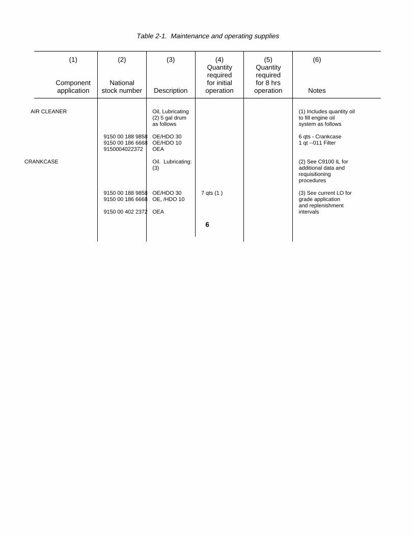
Table 2-1. Maintenance and operating supplies
(1) (2) (3) (4) (5) (6)Quantity Quantityrequired required
Component National for initial for 8 hrsapplication stock number Description operation operation Notes
AIR CLEANER Oil, Lubricating (1) Includes quantity oil(2) 5 gal drum to fill engine oilas follows system as follows
9150 00 188 9858 OE/HDO 30 6 qts - Crankcase9150 00 186 6668 OE/HDO 10 1 qt --011 Filter9150004022372 OEA
CRANKCASE Oil. Lubricating: (2) See C9100 IL for(3) additional data and
requisitioningprocedures
9150 00 188 9858 OE/HDO 30 7 qts (1 ) (3) See current LO for9150 00 186 6668 OE, /HDO 10 grade application
and replenishment9150 00 402 2372 OEA intervals
6
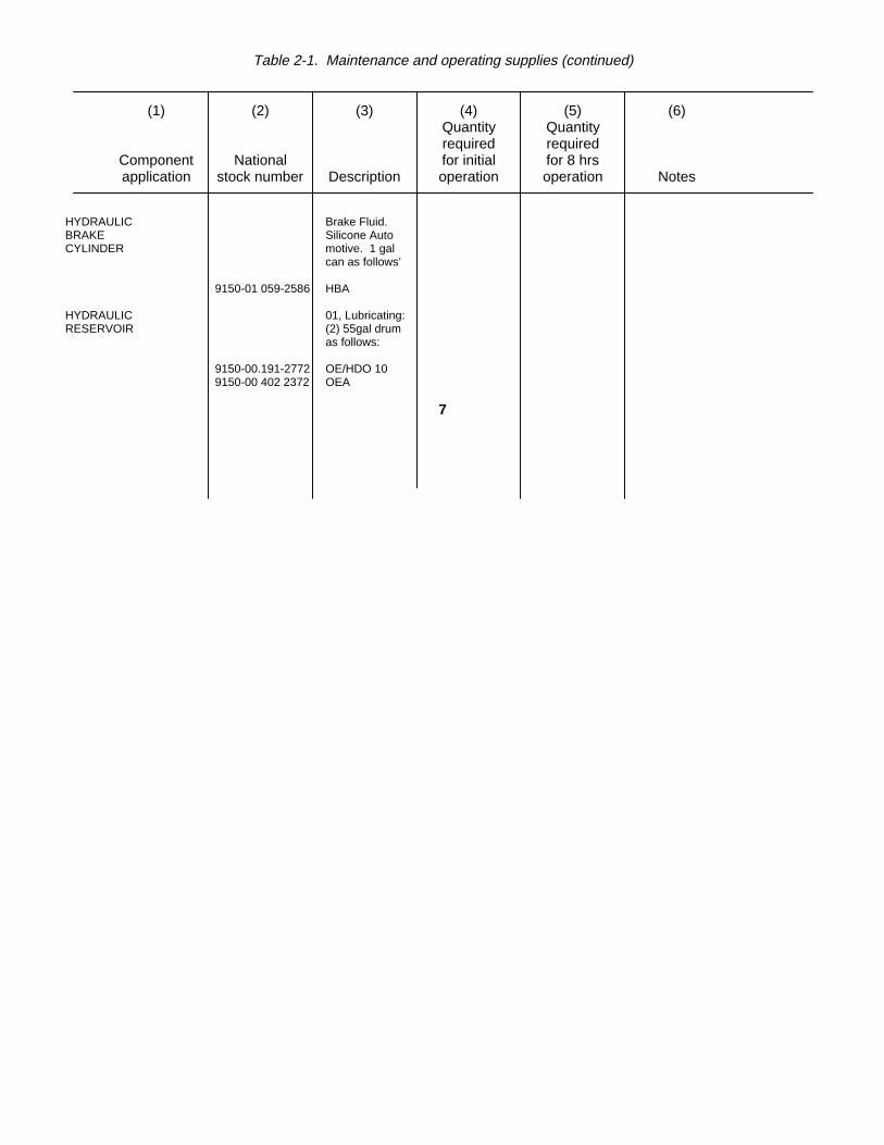
Table 2-1. Maintenance and operating supplies (continued)
(1) (2) (3) (4) (5) (6)Quantity Quantityrequired required
Component National for initial for 8 hrsapplication stock number Description operation operation Notes
HYDRAULIC Brake Fluid.BRAKE Silicone AutoCYLINDER motive. 1 gal
can as follows’
9150-01 059-2586 HBA
HYDRAULIC 01, Lubricating:RESERVOIR (2) 55gal drum
as follows:
9150-00.191-2772 OE/HDO 109150-00 402 2372 OEA
7
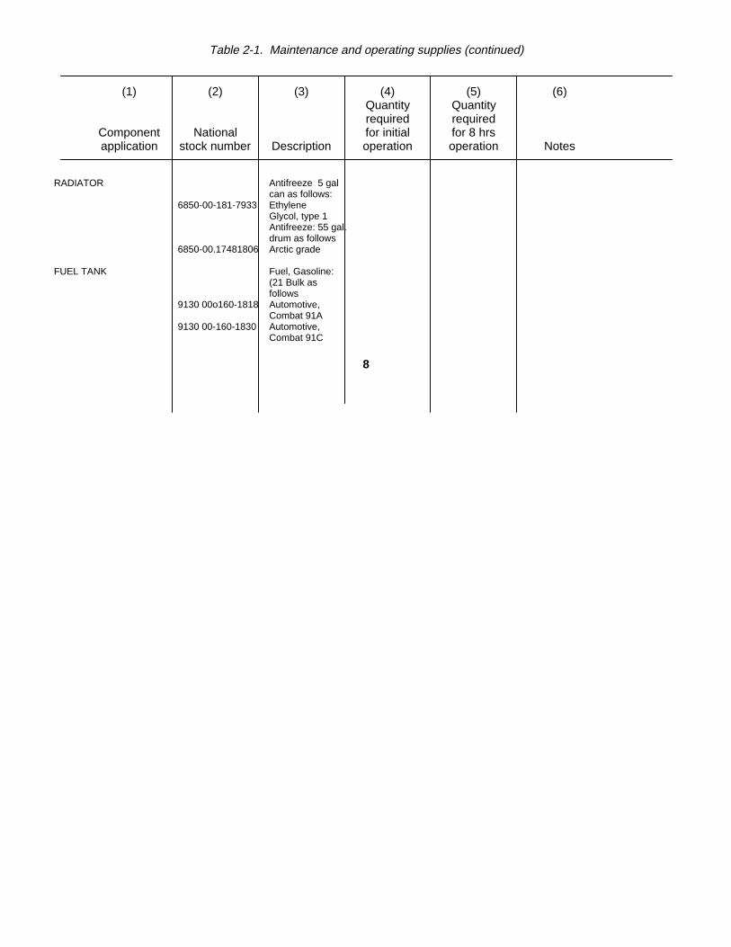
Table 2-1. Maintenance and operating supplies (continued)
(1) (2) (3) (4) (5) (6)Quantity Quantityrequired required
Component National for initial for 8 hrsapplication stock number Description operation operation Notes
RADIATOR Antifreeze 5 galcan as follows:
6850-00-181-7933 EthyleneGlycol, type 1Antifreeze: 55 gal.drum as follows
6850-00.17481806 Arctic grade
FUEL TANK Fuel, Gasoline:(21 Bulk asfollows
9130 00o160-1818 Automotive,Combat 91A
9130 00-160-1830 Automotive,Combat 91C
8

Table 2-1. Maintenance and operating supplies (continued)
(1) (2) (3) (4) (5) (6)Quantity Quantityrequired required
Component National for initial for 8 hrsapplication stock number Description operation operation Notes
TORQUE Oil. LubricatingCONVERTER. (2) 55 gal drumTRANSMIS- as follows:SION, ANDDIFFEREN 9150-00-191-2772 OE/HDO 10TIAL 9150-00-402 2372 OEA
GREASE Grease. Auto.POINTS motive and
Artillery. 5 lb.can as follows:
9150-00-190-0905 GAA
9
Section II, page 3-3, is superseded as follows:
Section II. OPERATOR/CREW PREVENTIVEMAINTENANCE CHECKS AND SERVICES
3-0. IntroductionTo insure that the truck is ready for operation at all times, it must be inspected systematically so that defects may bediscovered and corrected before they result in serious damage or failure. The preventive maintenance services to beperformed are listed in table 3-1. Defects discovered during operation of the truck will be noted for future correction. Stopoperation immediately if a deficiency is noted which would damage the equipment if operation were continued. Alldeficiencies will be recorded with corrective action taken on DA Form 2404 (Equipment Inspection and MaintenanceWorksheet) at the earliest possible opportunity.
a. Do your before (B) PREVENTIVE MAINTENANCE just before you operate the vehicle. Pay attention to theCAUTIONS and WARNINGS.
b. Do your (D) PREVENTIVE MAINTENANCE during operation. (During operation means to monitor the forkliftand its components/systems while they are actually being operated.)
c. Do your after (A) PREVENTIVE MAINTENANCE right after operating the vehicle. Pay attention to theCAUTIONS and WARNINGS.
d. Do your weekly (W) PREVENTIVE MAINTENANCE weekly.
10
e. Do your monthly (M) PREVENTIVE MAINTE-NANCE once a month.f. If something doesn’t work, troubleshoot it with the instructions in your TM 10-3930-618-10, or notify your
supervisor.g. Always do your PREVENTIVE MAINTENANCE in the same order so it gets to be a habit. Once you’ve had
some practice, you’ll spot anything wrong in a hurry,h. If anything looks wrong and you can’t fix it, write it on your DA Form 2404. If you find something seriously
wrong, report it to Organizational Maintenance RIGHT NOW.i. When you do your PREVENTIVE MAINTENANCE, take along the tools you will need to make all the checks.
Take along a rag; you’ll always need at least one.
WARNING
Dry cleaning solvent SD-2 is toxic and flammable. Wear protectivegoggles and gloves and use only in a well ventilated area. Avoid contactwith skin, eyes and clothes and don’t breathe vapors. Do not use nearopen flame or excessive heat. If you become dizzy while using cleaningsolvent, get fresh air immediately and get medical aid. If contact withskin or clothing is made, flush with water. If contact with eyes is made,wash your eyes with water and get medical aid immediately.
(1) Keep it clean: Dirt, grease, oil and debris only get in the way and may cover up a serious problem.Clean as you work and as needed. Use dry cleaning solvent (SD-2) on all metal surfaces. Use soap and water when youclean rubber or plastic material.
11

(2) Bolts, nuts and screws: Check them all for obvious looseness, missing, bent or broken condition. Youcan’t try them all with a tool, of course, but look for chipped paint, bare metal, or rust around bolt heads. If you find oneyou think is loose, tighten it, or report it to Organizational Maintenance if you cannot tighten it.
(3) Welds: Look for loose or chipped paint, rust or gaps where parts are welded together. If you find a badweld, report it to Organizational Maintenance.
(4) Electric wires and connectors: Look for cracked or broken insulation, bare wires, and loose or brokenconnectors. Tighten loose connectors and make sure the wires are in good shape.
(5) Hoses and fluid lines: Look for wear, damage and leaks and make sure clamps and fittings are tight.Wet spots show leaks, of course, but a stain around a fitting or connector can mean a leak. If a leak comes from a loosefitting or connector, tighten it. If something is broken or worn out, report it to Organizational Maintenance. Z. It isnecessary for you to know how fluid leakage affects the status of your vehicle. The following are definitions of thetypes/classes of leakage you need to know to be able to determine the status of your vehicle. Learn, then be familiar withthem and REMEMBER - WHEN IN DOUBT, NOTIFY YOUR SUPERVISOR!
Leakage Definitions for Organizational PMCS
Class I Seepage of fluid (as indicated by wetness or discoloration) not great enough to form drops.Class II Leakage of fluid great enough to form drops but not enough to cause drops to drip from item beingchecked/inspected.
12
Class III Leakage of fluid great enough to form drops that fall from the item being checked/inspected
CAUTIONEquipment operation is allowable with minor leakages (Class I or II). Ofcourse, consideration must be given to the fluid capacity in the item/system being checked/inspected. When in doubt, notify your supervisor.Exceptions are fuel and brake system, where no leakage is allowable.
CAUTIONWhen operating with Class I or II leaks, continue to check fluid levels asrequired in your PMCS.
Class III or fuel and brake system leaks should be reported to yoursupervisor or Organizational Maintenance.
k. Asterisks (*) will be used to identify Make, Model, and Characteristic of the engine on the Forklift Model No.F60-24PS.
(*) Make: Allis-Chalmers, Model: 6MB-230, Characteristic: Oil base air cleaner.(**) Make: Teledyne Continental, Model: F245-8518, Characteristic: Air cleaner element (Engine Replacement
Kit).
13
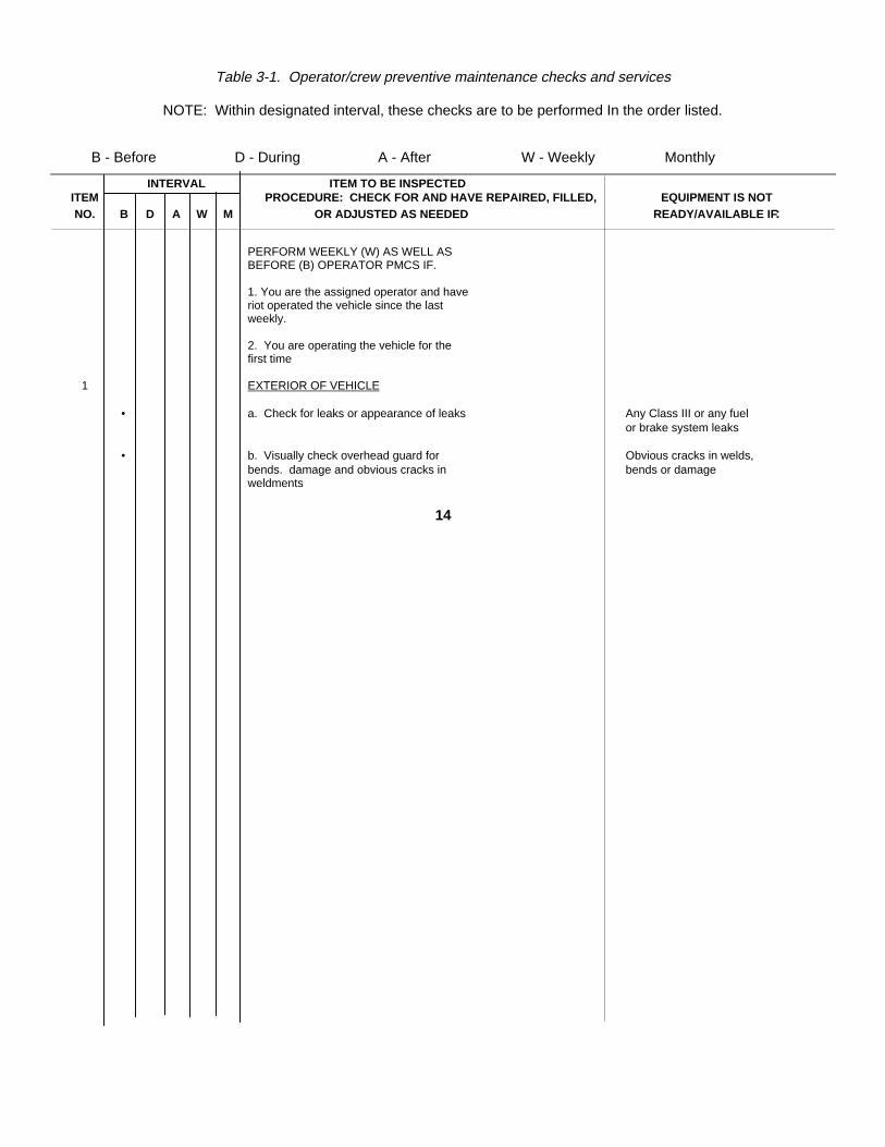
Table 3-1. Operator/crew preventive maintenance checks and services
NOTE: Within designated interval, these checks are to be performed In the order listed.
B - Before D - During A - After W - Weekly Monthly
INTERVAL ITEM TO BE INSPECTEDITEM PROCEDURE: CHECK FOR AND HAVE REPAIRED, FILLED, EQUIPMENT IS NOTNO. B D A W M OR ADJUSTED AS NEEDED READY/AVAILABLE IF:
PERFORM WEEKLY (W) AS WELL ASBEFORE (B) OPERATOR PMCS IF.
1. You are the assigned operator and haveriot operated the vehicle since the lastweekly.
2. You are operating the vehicle for thefirst time
1 EXTERIOR OF VEHICLE
• a. Check for leaks or appearance of leaks Any Class III or any fuelor brake system leaks
• b. Visually check overhead guard for Obvious cracks in welds,bends. damage and obvious cracks in bends or damageweldments
14
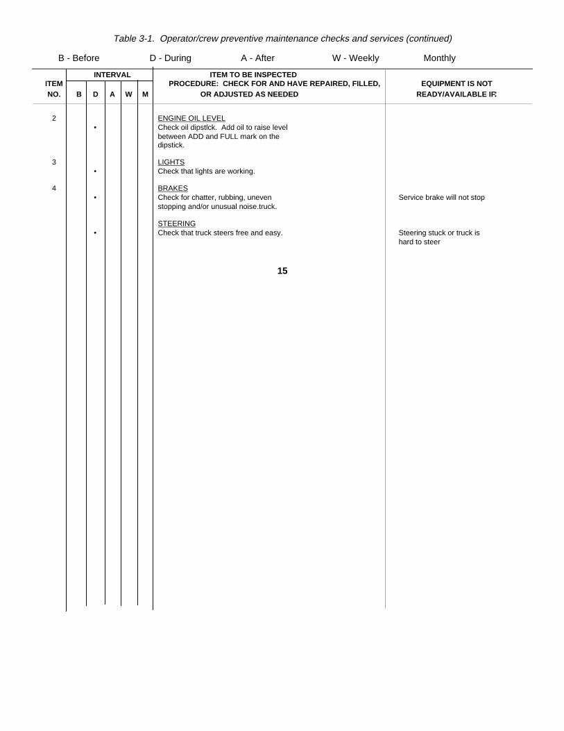
Table 3-1. Operator/crew preventive maintenance checks and services (continued)
B - Before D - During A - After W - Weekly Monthly
INTERVAL ITEM TO BE INSPECTEDITEM PROCEDURE: CHECK FOR AND HAVE REPAIRED, FILLED, EQUIPMENT IS NOTNO. B D A W M OR ADJUSTED AS NEEDED READY/AVAILABLE IF:
2 ENGINE OIL LEVEL• Check oil dipstlck. Add oil to raise level
between ADD and FULL mark on thedipstick.
3 LIGHTS• Check that lights are working.
4 BRAKES• Check for chatter, rubbing, uneven Service brake will not stop
stopping and/or unusual noise.truck.
STEERING• Check that truck steers free and easy. Steering stuck or truck is
hard to steer
15
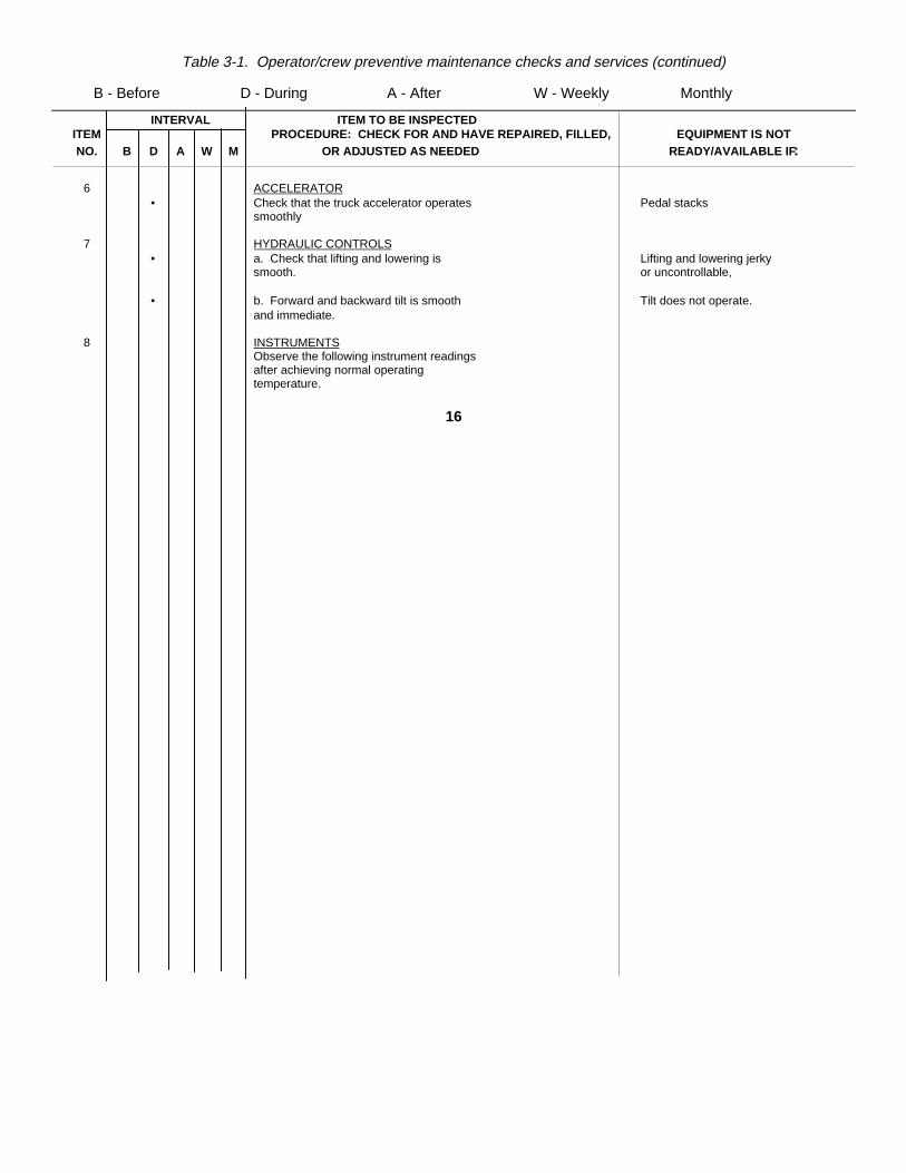
Table 3-1. Operator/crew preventive maintenance checks and services (continued)
B - Before D - During A - After W - Weekly Monthly
INTERVAL ITEM TO BE INSPECTEDITEM PROCEDURE: CHECK FOR AND HAVE REPAIRED, FILLED, EQUIPMENT IS NOTNO. B D A W M OR ADJUSTED AS NEEDED READY/AVAILABLE IF:
6 ACCELERATOR• Check that the truck accelerator operates Pedal stacks
smoothly
7 HYDRAULIC CONTROLS• a. Check that lifting and lowering is Lifting and lowering jerky
smooth. or uncontrollable,
• b. Forward and backward tilt is smooth Tilt does not operate.and immediate.
8 INSTRUMENTSObserve the following instrument readingsafter achieving normal operatingtemperature.
16
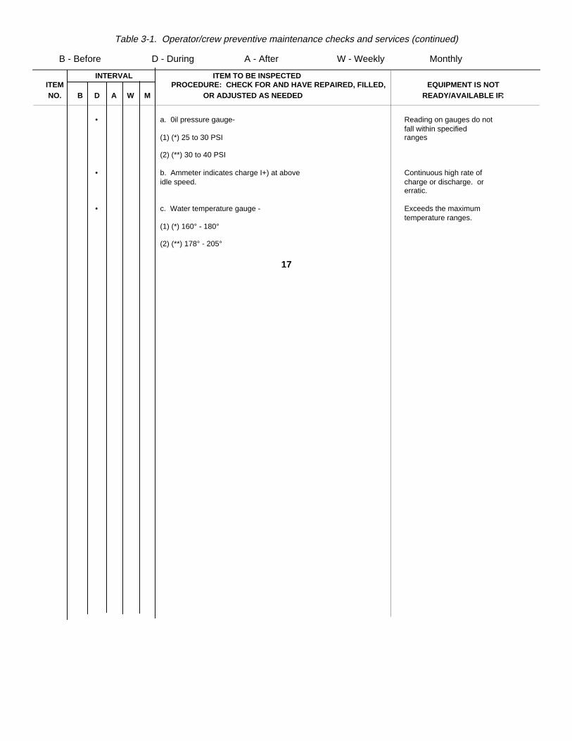
Table 3-1. Operator/crew preventive maintenance checks and services (continued)
B - Before D - During A - After W - Weekly Monthly
INTERVAL ITEM TO BE INSPECTEDITEM PROCEDURE: CHECK FOR AND HAVE REPAIRED, FILLED, EQUIPMENT IS NOTNO. B D A W M OR ADJUSTED AS NEEDED READY/AVAILABLE IF:
• a. 0il pressure gauge- Reading on gauges do notfall within specified
(1) (*) 25 to 30 PSI ranges
(2) (**) 30 to 40 PSI
• b. Ammeter indicates charge I+) at above Continuous high rate ofidle speed. charge or discharge. or
erratic.
• c. Water temperature gauge - Exceeds the maximumtemperature ranges.
(1) (*) 160° - 180°
(2) (**) 178° - 205°
17
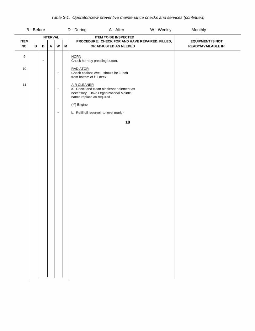
Table 3-1. Operator/crew preventive maintenance checks and services (continued)
B - Before D - During A - After W - Weekly Monthly
INTERVAL ITEM TO BE INSPECTEDITEM PROCEDURE: CHECK FOR AND HAVE REPAIRED, FILLED, EQUIPMENT IS NOTNO. B D A W M OR ADJUSTED AS NEEDED READY/AVAILABLE IF:
9 HORN• Check horn by pressing button,
10 RADIATOR• Check coolant level - should be 1 inch
from bottom of f1ll neck
11 AIR CLEANER• a. Check and clean air cleaner element as
necessary. Have Organizational Maintenance replace as required -
(**) Engine
• b. Refill oil reservoir to level mark -
18
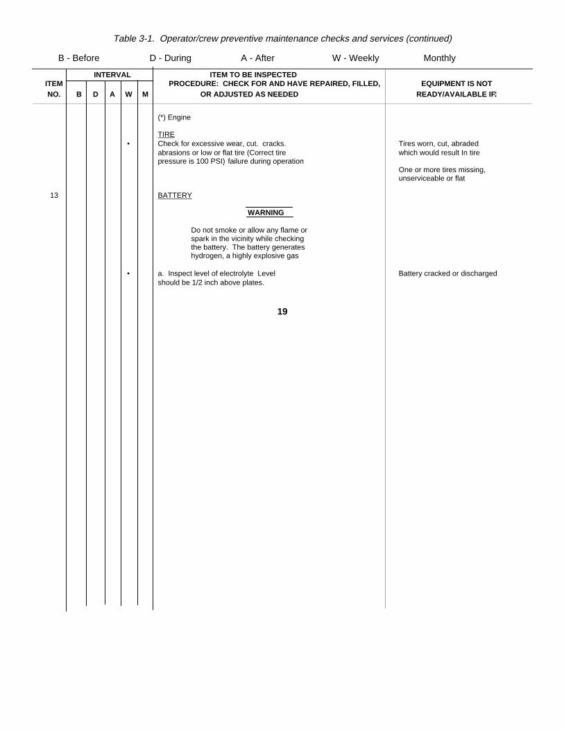
Table 3-1. Operator/crew preventive maintenance checks and services (continued)
B - Before D - During A - After W - Weekly Monthly
INTERVAL ITEM TO BE INSPECTEDITEM PROCEDURE: CHECK FOR AND HAVE REPAIRED, FILLED, EQUIPMENT IS NOTNO. B D A W M OR ADJUSTED AS NEEDED READY/AVAILABLE IF:
(*) Engine
TIRE• Check for excessive wear, cut. cracks. Tires worn, cut, abraded
abrasions or low or flat tire (Correct tire which would result In tirepressure is 100 PSI) failure during operation
One or more tires missing,unserviceable or flat
13 BATTERY
WARNING
Do not smoke or allow any flame orspark in the vicinity while checkingthe battery. The battery generateshydrogen, a highly explosive gas
• a. Inspect level of electrolyte Level Battery cracked or dischargedshould be 1/2 inch above plates.
19
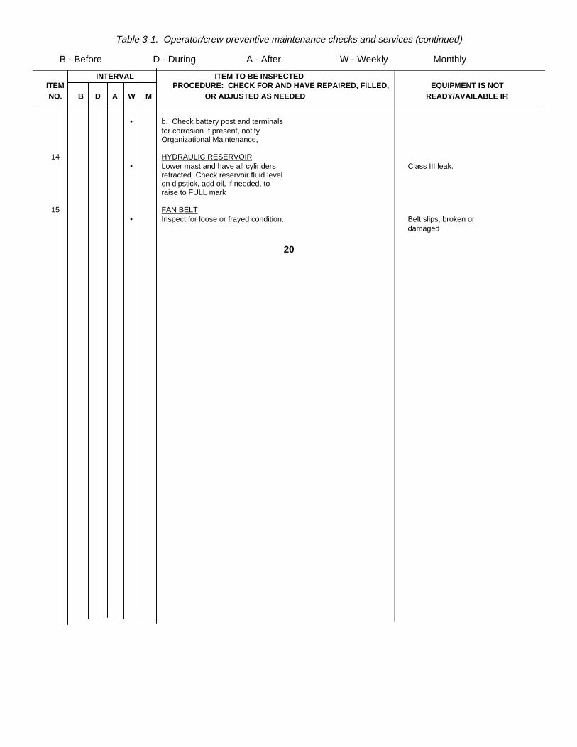
Table 3-1. Operator/crew preventive maintenance checks and services (continued)
B - Before D - During A - After W - Weekly Monthly
INTERVAL ITEM TO BE INSPECTEDITEM PROCEDURE: CHECK FOR AND HAVE REPAIRED, FILLED, EQUIPMENT IS NOTNO. B D A W M OR ADJUSTED AS NEEDED READY/AVAILABLE IF:
• b. Check battery post and terminalsfor corrosion If present, notifyOrganizational Maintenance,
14 HYDRAULIC RESERVOIR• Lower mast and have all cylinders Class III leak.
retracted Check reservoir fluid levelon dipstick, add oil, if needed, toraise to FULL mark
15 FAN BELT• Inspect for loose or frayed condition. Belt slips, broken or
damaged
20
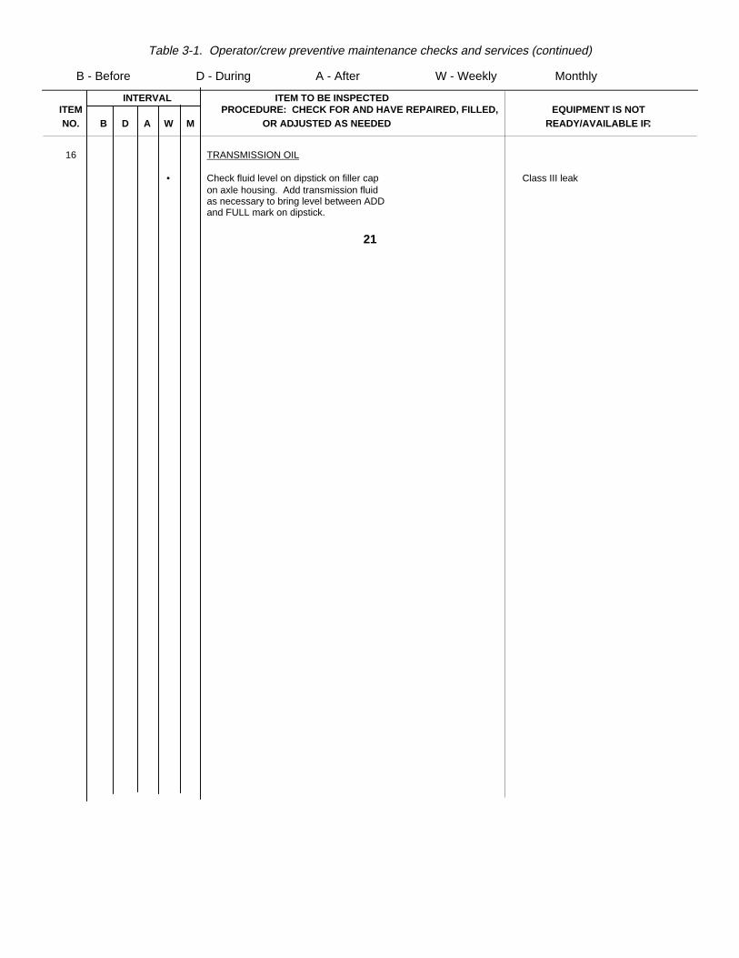
Table 3-1. Operator/crew preventive maintenance checks and services (continued)
B - Before D - During A - After W - Weekly Monthly
INTERVAL ITEM TO BE INSPECTEDITEM PROCEDURE: CHECK FOR AND HAVE REPAIRED, FILLED, EQUIPMENT IS NOTNO. B D A W M OR ADJUSTED AS NEEDED READY/AVAILABLE IF:
16 TRANSMISSION OIL
• Check fluid level on dipstick on filler cap Class III leakon axle housing. Add transmission fluidas necessary to bring level between ADDand FULL mark on dipstick.
21
Page A-1. Appendix A, change "TM 9-6140-200-15" to read "TM 9-6140-200-14". After section A-3, Maintenance, add thefollowing:
A-3. MaintenanceChange "TM 38-750" to read "DA PAM 735-750". After section A-3, Maintenance, add the following:
A-4. Environmental HealthTB MED 501Occupational and Environmental Health Hearing Conservation
Page B-1. Appendix B is superseded as follows:
APPENDIX BBASIC ISSUE ITEMS LIST AND ITEMS
TROOP INSTALLED OR AUTHORIZED LISTSection I. INTRODUCTION
B-1. Scope. This appendix lists items required by the operator for operation of the fork lift truck.B-2. General. This list is divided into the following sections:
a. Basic Issue Items List - Section III. Not applicable.b. Items Troop Installed or Authorized List- Section Il/.
A list of items in alphabetical sequence, which at the discretion of the unit commander, may accompany the fork lift truck.These items are not subject to turn-in with the truck when it is evacuated.
22
B-3. Explanation of Columns. The following provides an explanation of columns in the tabular list of items troopinstalled or authorized, section III.
a. Source, Maintenance, and Recoverability Code(s) (SMR).(1) Source code indicates the source for the listed item. Source codes are:
Code ExplanationP Repair parts, special tools and test equipment supplied from GSA/DSA or Army supply system and
authorized for use at indicated maintenance levels.
Code ExplanationP 2Repair parts, special tools, and test equipment which are procured and stocked for insurance purposes -
s because the combat or military essentiality ot the end item dictates that a minimum quantity be availablein the supply system.
(2) Maintenance code, indicates the lowest level of maintenance authorized to install the listed item. Themaintenance level code is:
Code ExplanationC Crew/Operator
23
(3) Recoverability code indicates whether unserviceable items should be returned for recovery or salvage.Items not coded are unrecoverable. Recoverability codes are:
Code ExplanationR Applied to repair parts (assemblies and components), special tools, and test equipment which are
considered economically repairable at direct support and general support maintenance levels.S Repair parts, special tools, test equipment, and assemblies which are economically repairable at DSU and
GSU activities and which normally are furnished by supply on an exchange basis.
b. National Stock Number. This column indicates the National stock number assigned to the item which will beused for requisitioning purposes.
c. Description. This column indicates the National item name and any additional description of the itemrequired.
d. Unit of Measure (U/Mi. A 2-character alphabetic abbreviation indicating the amount or quantity of the itemupon which the allowances are based; e.g., ft, ea, pr; etc.
e. Quantity Authorized. This column indicates the quantity of the item authorized to be used with the equipment.
24
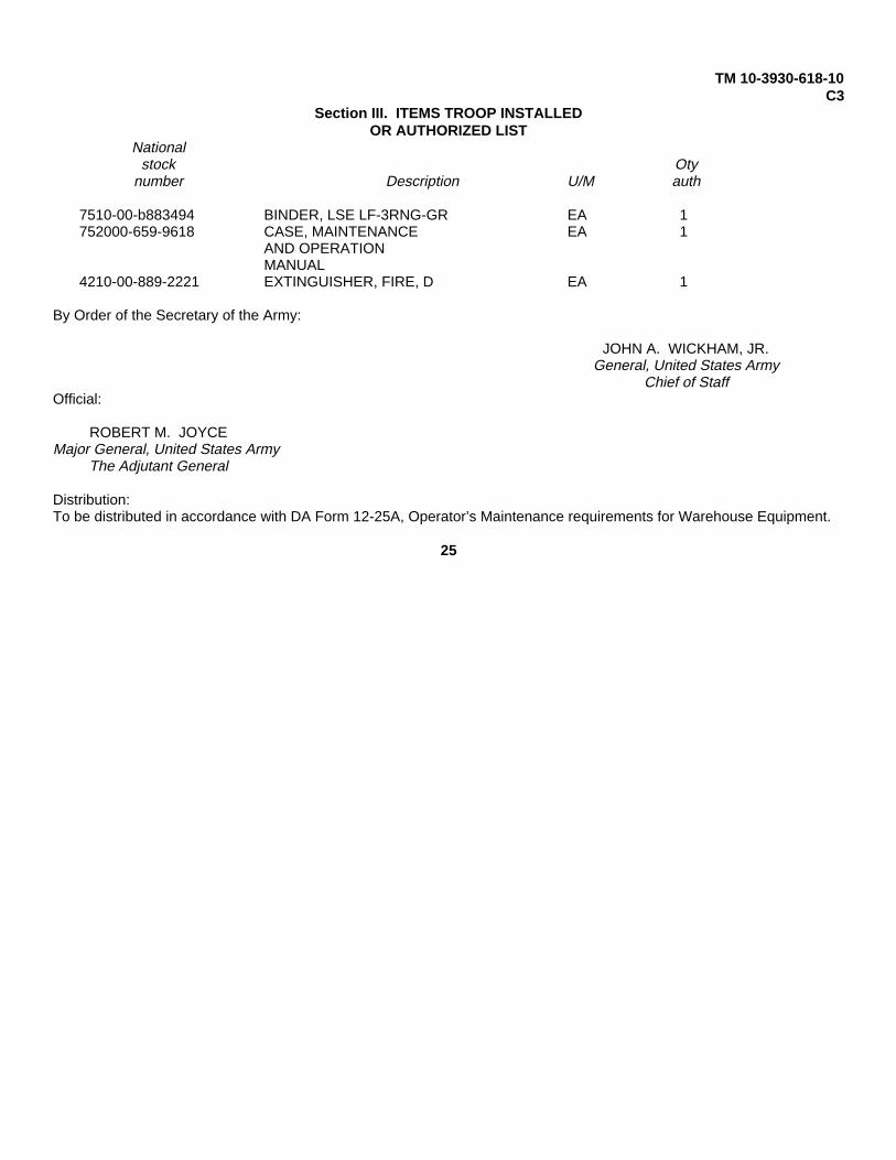
TM 10-3930-618-10C3
Section III. ITEMS TROOP INSTALLEDOR AUTHORIZED LIST
Nationalstock Oty
number Description U/M auth
7510-00-b883494 BINDER, LSE LF-3RNG-GR EA 1752000-659-9618 CASE, MAINTENANCE EA 1
AND OPERATIONMANUAL
4210-00-889-2221 EXTINGUISHER, FIRE, D EA 1
By Order of the Secretary of the Army:
JOHN A. WICKHAM, JR.General, United States Army
Chief of StaffOfficial:
ROBERT M. JOYCEMajor General, United States Army
The Adjutant General
Distribution:To be distributed in accordance with DA Form 12-25A, Operator’s Maintenance requirements for Warehouse Equipment.
25
*TM 10-3930-618-10Technical Manual Headquarters
Department or the ArmyNo 10-3930-61S8-10 Washington, D. C, 22 November 1971
OPERATOR’S MANUAL
TRUCK, LIFT, FORK; GASOLINEENGINE DRIVEN; PNEUMATIC TIRED
WHEELS; 6000-LB CAPACITY; 168-INCHLIFT; ALLIS-CHALMERS MODEL
FP60-24PS; ARMY MODEL MHE-213,FSN 3930-935-7979
Paragraph PageChapter 1. INTRODUCTlONSection I. General. ............................................................................................................. 1-1 - 1-3 1-1
II. Description and data............................................................................................ 1-4, 1-5 1-1Chapter 2. OPERATING INSTRUCTIONSChapter 3. MAINTENANCE INSTRUCTIONSSection I. Lubrication ........................................................................................................... 3-1
II. Preventive maintenance checks andservices ............................................................................................................... 3-3
III. Maintenance procedures ..................................................................................... 3-1 - 3-6 3-7Appendix A REFERENCES. ................................................................................................. A-1Appendix B MAINTENANCE AND OPERATING ................................................................... A-1
SUPPLIES. ........................................................................................................ B-1
*This manual supersedes TM 10-3930-618-10, 2 February, 1971
i
}
CHAPTER 1INTRODUCTION
Section I. GENERAL
1-1. Purpose and ScopeThis manual is for your use in operating the Allis-Chalmers 6, 000-lb. forklift truck, Army Model MHE-213.
1-2. Maintenance Forms and RecordsMaintenance forms and records you are required to use are explained in TM 38-750.
1-3. Recommending ImprovementsYou can improve this manual by recommending improvements, using DA Form 2028 (Recommended Changes toPublications) or a letter and mail direct to Commanding General, U. S. Army Mobility Equipment Command, ATTN.AMSME-MPP, 4300 Goodfellow Boulevard, St. Louis, Mo. 63120 A reply will be furnished direct to youSection II. DESCRIPTION AND DATA
1-4. DescriptionThe forklift truck is powered by a 6-cylinder gasoline engine; it has a lifting capacity of 6, 000 pounds; and a
1-1

lifting height of 168 inches. The truck is designed primarily for use in a warehouse or on a hard surface pavement. Apower-steering booster cylinder provides maximum steering control of the truck. A single lever shift control mounted onthe steering column is used to control the direction of travel. Lift and tilt cylinder controls are located to the right of theoperator. If you need a detailed description of any component of the truck, refer to TM 10-3930-618-20 which is availableat organizational maintenance
1-2
Figure 1-1. Left-front view of truck.
Figure 1-2. Right-rear view of truck
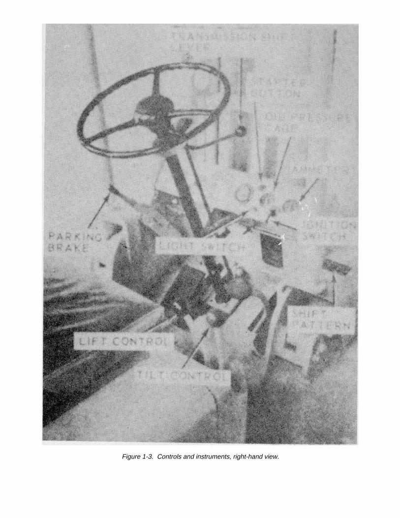
Figure 1-3. Controls and instruments, right-hand view.
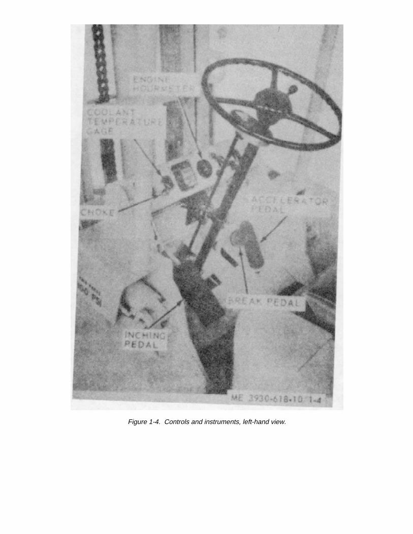
Figure 1-4. Controls and instruments, left-hand view.
1-5. Tabulated Dataa. Component Capacities (approx)
Radiator ........................................................................................................................................................... 16 qts.Transmission. ................................................................................................................................................ 10 qtsDrive axle......................................................................................................................................................... 5 ptsHydraulic tank.................................................................................................................................................. 7 2 galFuel tank.......................................................................................................................................................... 14 5 gal
b. Truck Characteristics.Length including forks ..................................................................................................................................... 12 ft 4 inForward speed................................................................................................................................................. 12 mphReverse speed ................................................................................................................................................ 12 mphLift height . .................................................................................................................................................... 168 inForward mast tilt .............................................................................................................................................. 3°Reverse mast tilt.............................................................................................................................................. 10°Turning radius ................................................................................................................................................. 8 ft 2 inUnder clearance or mast ................................................................................................................................. 6 in
1-7
CHAPTER 2OPERATING INSTRUCTIONS
NOTEThe operator must possess a valid SF-46 (U. S. Government VehicleOperators Identification Card) be-fore operating this truck.
2-1. Startinga. Perform the daily preventive maintenance procedures described in table 3-1.b. Start the engine as follows:
(1) Engage the parking brake, if not previously engaged, by pulling up on lever.(2) Transmission shift lever must be in NEUTRAL position.(3) Pull choke out half-way.(4) Depress accelerator pedal slightly.(5) Turn ignition switch to ON position; press starter button. Release button when engine starts. If engine
fails to start when starter button is pressed, pull choke out all the way. Do not press starter button more than 3-to-4-seconds at a time.
(6) Check oil pressure gage. Pressure should be between 20- and 30-pounds(7) Check ammeter. Ammeter should indicate charge (+) at above idle speed.(8) After engine is warm, push choke button in.
2-1
2-2. Operating the Trucka. Lift and Tilt Controls.
(1) To raise the forks, pull the lift control lever back. Push the lift control lever forward to lower the forks.When the lift control level is released, it will re-turn automatically to hold position and lifting or lower-ing operation will stop.
(2) To tilt the mast forward, push the tilt control lever forward. Pull the tilt control lever back to tilt the forksback. When the tilt control lever is released, it will return automatically to hold position and tilting operation will stop.
(3) Raise the forks high enough from the surface to prevent dragging when moving before putting truck inmotion.
b. Truck Operating Controls.(1) Move transmission shift lever UP for forward motion and DOWN for reverse motion.(2) Release parking brake by pushing forward on lever. Hold truck in place with foot brake pedal.(3) Depress accelerator to increase engine speed and move truck in direction selected.(4) Depress brake pedal to stop truck.
CAUTIONCome to a complete stop before changing direction.
(5) The inching control pedal permits smooth maneuvering of the truck when high engine speeds are
2-2
necessary to perform lifting or tilting operations. When depressed, the inching pedal can be used to reduce travelingspeed to a stop if required.
c. Lifting the Load.(1) Move truck slowly and carefully into position and engage load properly. Truck should be square with
load; forks spaced evenly between pallet stringers, and apart as far as possible.(2) Move forward until load touches carriage.(3) Tilt mast back; then lift load smoothly. Lifting speed is controlled by engine speed.(4) When lifting drums or round objects, tilt mast forward and slide fork tips along floor to get under drum.
Tilt mast backward until drum is cradled before lifting. Drums with large ribs may be lifted in upright position if forks can bespaced accurately enough for good safe grip under ribs.
d. Traveling with Load.(1) Tilt mast back to cradle load. Lift load only as high as required to maintain clearance from floor.(2) Operate forward on up grades and in reverse on down grades. For better vision, operate in reverse
when carrying bulky loads(3) When turning sharp corners, keep close to in-side corner and begin turn when inside drive wheel meets
corner. When turning in narrow aisles keep as far from stockpiles as possible when turning into aisle.(4) Always enter railway cars at an angle; never
2-3
go straight in.e. Unloading.
(1) Move truck into unloading position, tilt mast forward only when directly over unloading area.(2) Deposit load; then back away carefully to dis-
engage forks.
2-3. Stopping the Trucka. Park truck only in authorized areas.b. Place transmission shift lever in NEUTRAL position.c. Engage parking brake.d. Lower forks to floor.e. Turn ignition switch to OFF position to stop the engine.f. Chock the wheels when parking on an incline.
2-4

CHAPTER 3MAINTENANCE INSTRUCTIONS
Section I. LUBRICATION
Lubrication of the truck is the responsibility of organizational maintenance. The operator will perform those lubricationservices necessary to keep the truck in operation. Figure 3-1 locates the check points and types of lubricants to be used.
3-1
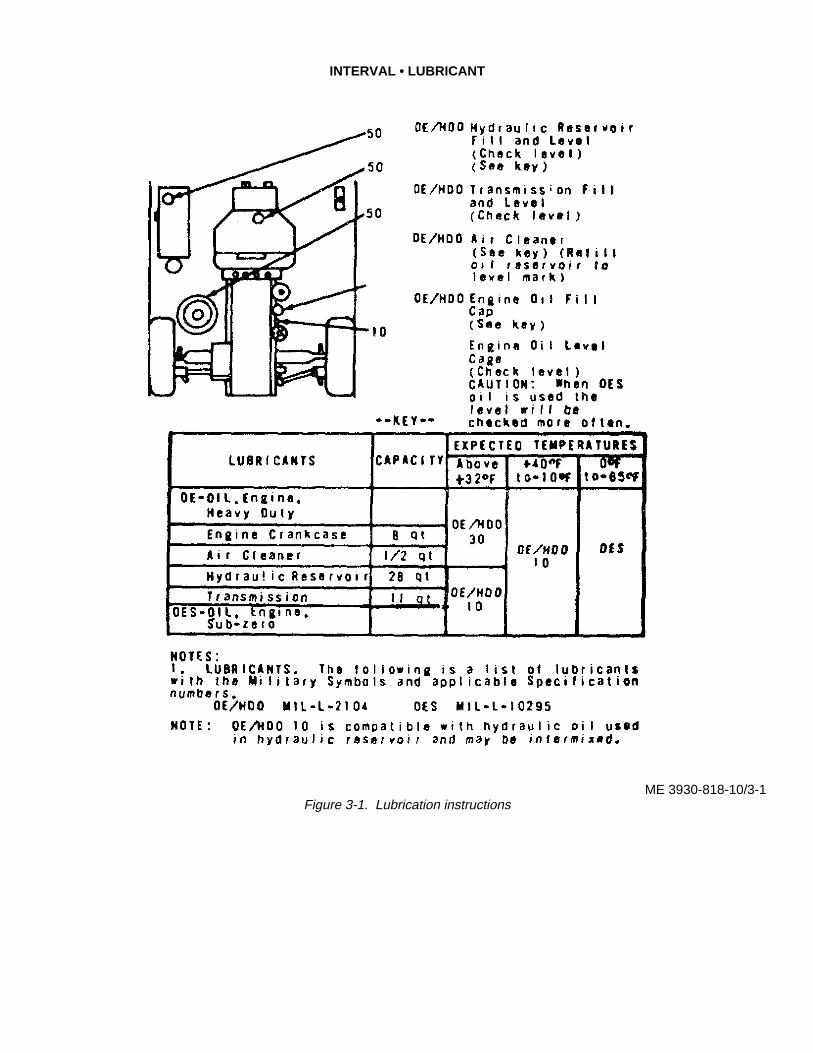
INTERVAL • LUBRICANT
ME 3930-818-10/3-1Figure 3-1. Lubrication instructions

Section II. PREVENTIVE MAINTENANCECHECKS AND SERVICES
To insure that the truck is ready for operation at all times, it must be inspected systematically so that defects may bediscovered and corrected before they result in serious damage or failure. The preventive mainte-nance services to beperformed are listed in table 3-1. Defects discovered during operation of the truck will be noted for future correction. Stopoperation immediately if a deficiency is noted which would damage the equip-ment if operation were continued. Alldeficiencies will be recorded with corrective action taken on DA Form 2404 (Equipment Inspection and Maintenance Work-sheet) at the earliest possible opportunity.
3-3
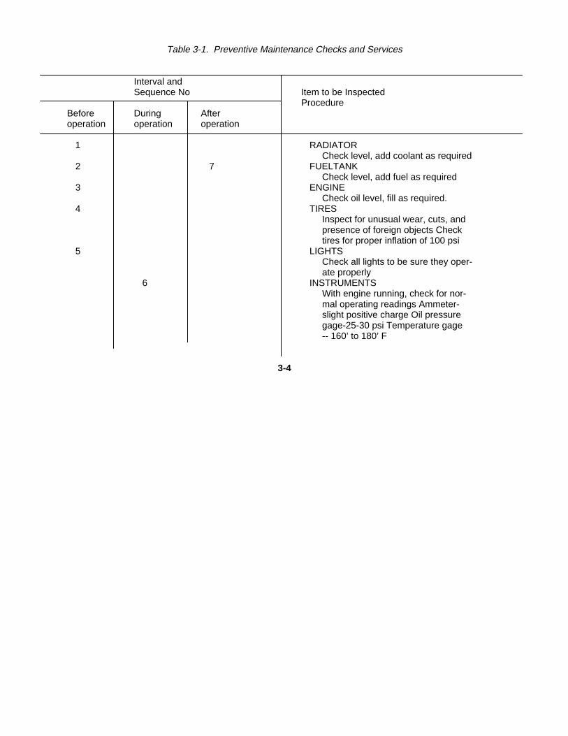
Table 3-1. Preventive Maintenance Checks and Services
Interval andSequence No Item to be Inspected
ProcedureBefore During Afteroperation operation operation
1 RADIATORCheck level, add coolant as required
2 7 FUELTANKCheck level, add fuel as required
3 ENGINECheck oil level, fill as required.
4 TIRESInspect for unusual wear, cuts, andpresence of foreign objects Checktires for proper inflation of 100 psi
5 LIGHTSCheck all lights to be sure they oper-ate properly
6 INSTRUMENTSWith engine running, check for nor-mal operating readings Ammeter-slight positive charge Oil pressuregage-25-30 psi Temperature gage-- 160’ to 180’ F
3-4
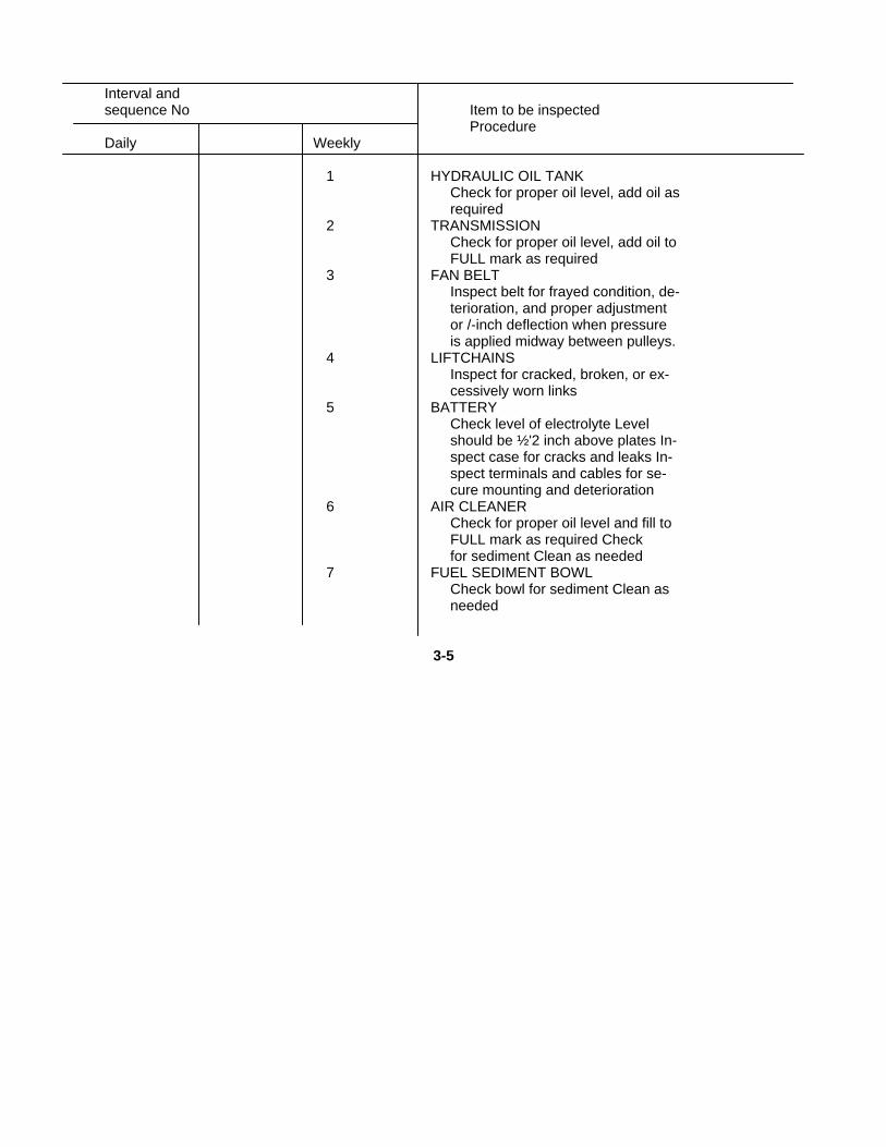
Interval andsequence No Item to be inspected
ProcedureDaily Weekly
1 HYDRAULIC OIL TANKCheck for proper oil level, add oil asrequired
2 TRANSMISSIONCheck for proper oil level, add oil toFULL mark as required
3 FAN BELTInspect belt for frayed condition, de-terioration, and proper adjustmentor /-inch deflection when pressureis applied midway between pulleys.
4 LIFTCHAINSInspect for cracked, broken, or ex-cessively worn links
5 BATTERYCheck level of electrolyte Levelshould be ½'2 inch above plates In-spect case for cracks and leaks In-spect terminals and cables for se-cure mounting and deterioration
6 AIR CLEANERCheck for proper oil level and fill toFULL mark as required Checkfor sediment Clean as needed
7 FUEL SEDIMENT BOWLCheck bowl for sediment Clean asneeded
3-5

Section III. MAINTENANCE PROCEDURES
3-1. Air Cleaner(fig. 3-2)
The oil bath type air cleaner is mounted on the left side hood support angle. To service the air cleaner proceed as follows:a. Loosen and remove the wingnut and washer that secures the air cleaner to the bottom of the angle.b. Lift air cleaner baffle and air cleaner top from lower body.c. Empty oil from lower body and clean body with solvent-saturated cloth. Dry thoroughly.d. Fill lower body to indicated level with clean engine oil of the type used in the engine crankcase.e. Position air cleaner and baffle in place and secure with washer and wingnut.
3-6
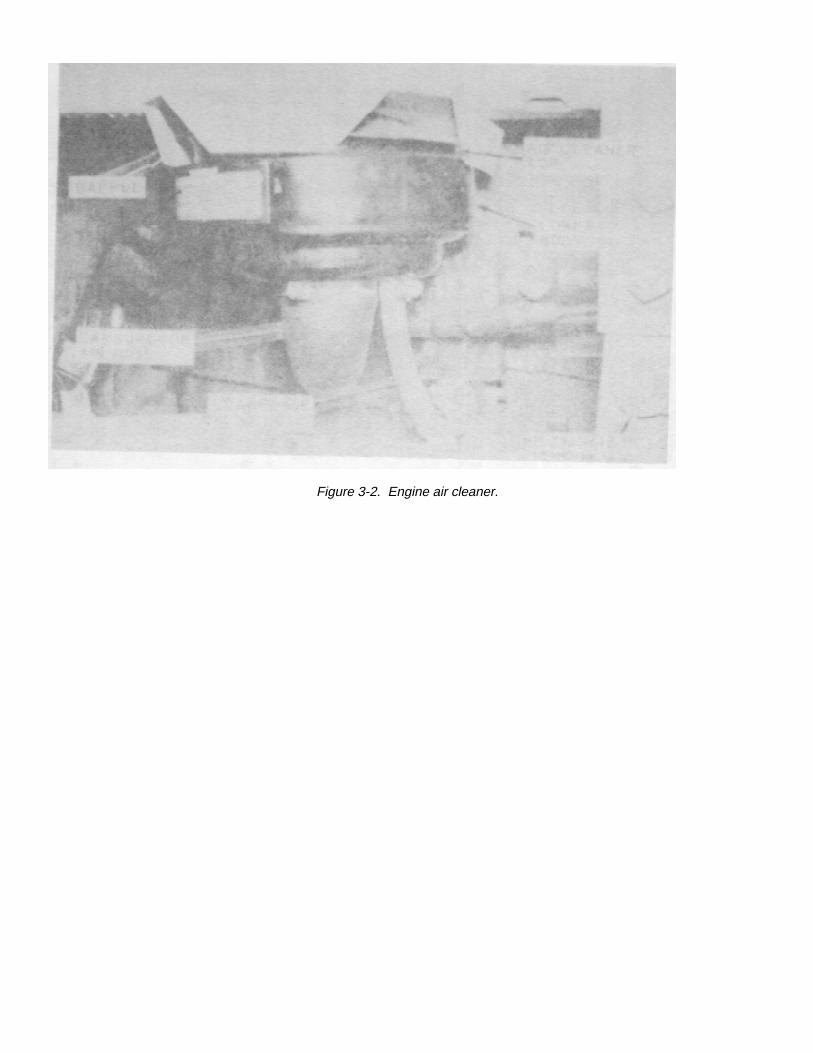
Figure 3-2. Engine air cleaner.
3-2. Crankcase Oil LevelIn order to obtain an accurate measurement of the level of oil in the crankcase, the engine must be stopped and the truckparked on level ground. Allow at least 5 minutes for the oil to drain back into the oil pan. With-draw the dipstick which islocated on the right side of the engine and wipe clean. Reinsert all the way and then remove for a true reading. Add oil asnecessary to bring oil level up to FULL mark on stick. In cold weather sludge formation will increase and oil changes maybe required more frequently to eliminate contamination.
3-3. Transmission Fluid LevelThe transmission fluid dipstick is reached through the opening in the grill at the rear of the operator’s right foot. With theengine running and the fluid hot, with-draw the dipstick and check the fluid level. Add fluid through the dipstick opening toraise the level to the FULL mark on the dipstick. Refer to the lubrication order for the correct transmission fluid to use.
3-4. RadiatorCheck the coolant level in the radiator. Level should be 1-inch from bottom of fill neck. Use equal parts water and glycolbase antifreeze when replenishing coolant. Check the area of the water pump for evidence
3-8
of leaking coolant. Refer to organizational maintenance for corrective action.
3-5. Battery
WARNINGDo not smoke or allow open flames near charging batteries. Severe injury from ex-plosion or acid may result. Avoid contact with electrolyte or clothing or flesh.
Check the electrolyte level weekly. Add distilled water if necessary. Keep the top of the battery clean.
3-6. Fuel Filter(fig. 3-3).a. Loosen thumbnut on filter bail, swing bail to one side, and remove filter bowl and screen.b. Clean bowl and screen with SD, P-D680. Be sure no sediment or lint remains in bowl or on screen.c. Reinstall gasket, screen, and bowl. Swing bail into place and tighten nut.
3-9
Figure 3-3. Fuel filer.
APPENDIX AREFERENCES
A-1. Fire ProtectionTB 5-4200-200-10 Hand Portable Fire Ex-
tinguishers Approvedfor Army Users
A-2. LubricationC9100IL Fuels, Lubricants, Oils,
and Waxes
A-3. MaintenanceTB750-651 Use of Antifreeze Solu-
tions and CleaningCompounds in EngineCooling Systems
TM 9-6140-200-15 Operation and Organiza-tional, Field and DepotMaintenance; StorageBatteries, Lead-AcidType
TM38-750 The Army MaintenanceManagement System(TAMMS)
A-1
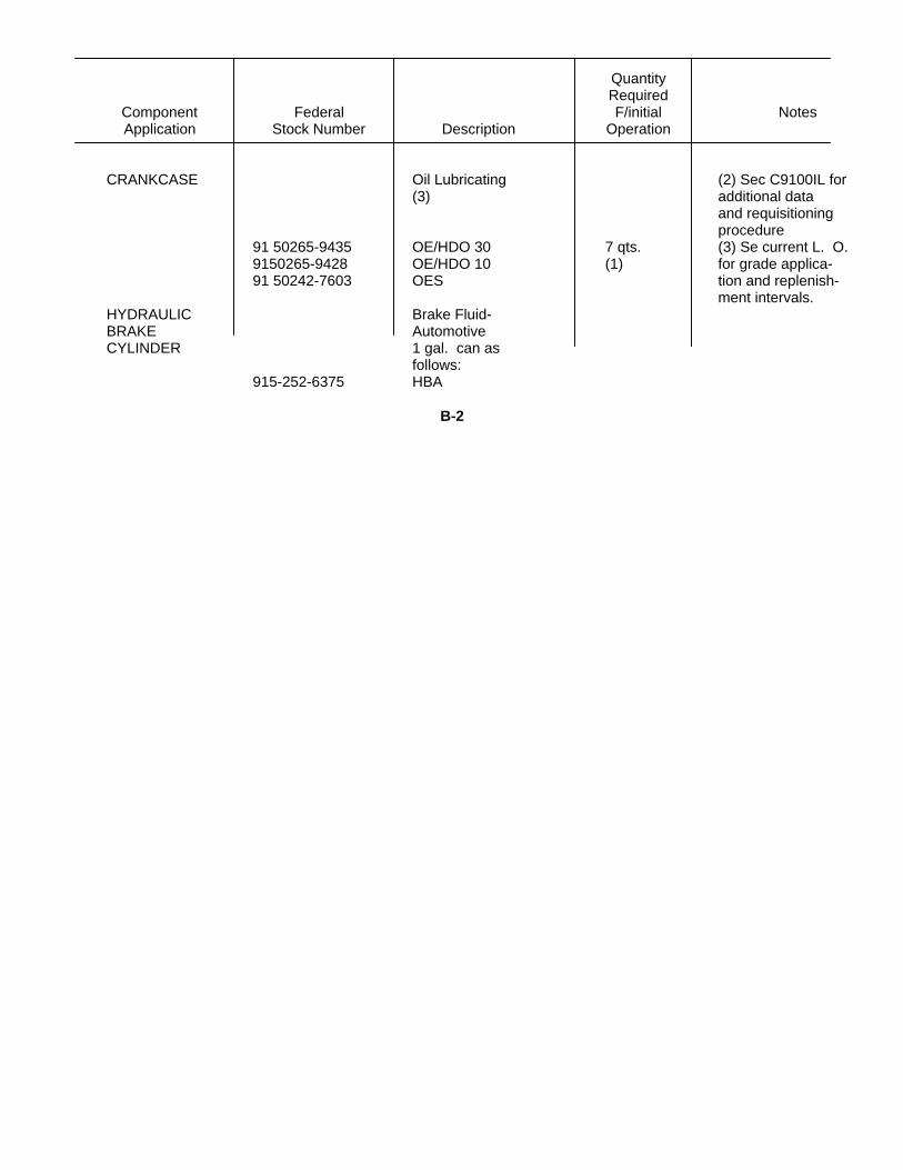
APPENDIX BMAINTENANCE AND OPERATING SUPPLIES
QuantityRequired
Component Federal F/initial NotesApplication Stock Number Description Operation
AIR CLEANER Oil Lubricating: (1) Include quantity(2) of oil to fill engine5 gal. drum as oil system afollows. follows.
9150-265-9435 OE/HDO 6qts. -30
9150-265-9428 OE/HDO Crankcase10
9150-242-7603 OES 1 qt. - OilFilter
B-1
QuantityRequired
Component Federal F/initial NotesApplication Stock Number Description Operation
CRANKCASE Oil Lubricating (2) Sec C9100IL for(3) additional data
and requisitioningprocedure
91 50265-9435 OE/HDO 30 7 qts. (3) Se current L. O.9150265-9428 OE/HDO 10 (1) for grade applica-91 50242-7603 OES tion and replenish-
ment intervals.HYDRAULIC Brake Fluid-BRAKE AutomotiveCYLINDER 1 gal. can as
follows:915-252-6375 HBA
B-2
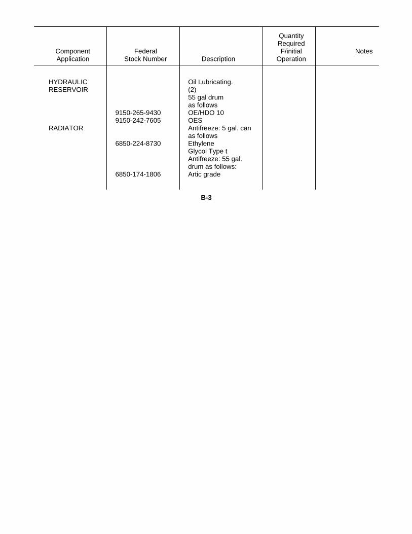
QuantityRequired
Component Federal F/initial NotesApplication Stock Number Description Operation
HYDRAULIC Oil Lubricating.RESERVOIR (2)
55 gal drumas follows
9150-265-9430 OE/HDO 109150-242-7605 OES
RADIATOR Antifreeze: 5 gal. canas follows
6850-224-8730 EthyleneGlycol Type tAntifreeze: 55 gal.drum as follows:
6850-174-1806 Artic grade
B-3
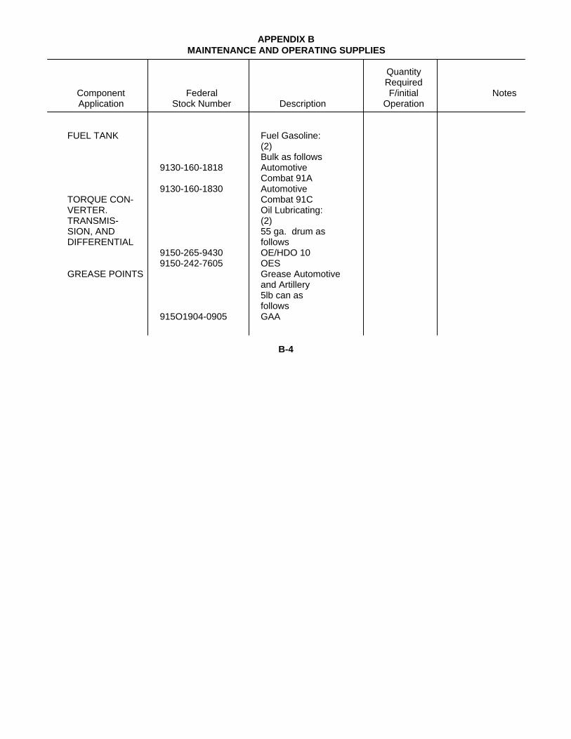
APPENDIX BMAINTENANCE AND OPERATING SUPPLIES
QuantityRequired
Component Federal F/initial NotesApplication Stock Number Description Operation
FUEL TANK Fuel Gasoline:(2)Bulk as follows
9130-160-1818 AutomotiveCombat 91A
9130-160-1830 AutomotiveTORQUE CON- Combat 91CVERTER. Oil Lubricating:TRANSMIS- (2)SION, AND 55 ga. drum asDIFFERENTIAL follows
9150-265-9430 OE/HDO 109150-242-7605 OES
GREASE POINTS Grease Automotiveand Artillery5lb can asfollows
915O1904-0905 GAA
B-4
By Order of the Secretary of the Army-
W. C. WESTMORELAND,General, United States Army,
Official Chief of Staff
VERN L. BOWERSMajor General, United States Army,
The Adjutant General
Distribution:To be distributed In accordance with DA Form 12-25, Sec (qty rqr BIock #193).Operator requirements for Truck, Fork Lift, Gasoline
* U. S. GOVERNMENT PRINTING OFFICE : 1993 0 - 342-421 (80733)

PIN: 028300-000
This fine document...
Was brought to you by me:
Liberated Manuals -- free army and government manuals
Why do I do it? I am tired of sleazy CD-ROM sellers, who take publicly available information, slap “watermarks” and other junk on it, and sell it. Those masters of search engine manipulation make sure that their sites that sell free information, come up first in search engines. They did not create it... They did not even scan it... Why should they get your money? Why are not letting you give those free manuals to your friends?
I am setting this document FREE. This document was made by the US Government and is NOT protected by Copyright. Feel free to share, republish, sell and so on.
I am not asking you for donations, fees or handouts. If you can, please provide a link to liberatedmanuals.com, so that free manuals come up first in search engines:
<A HREF=http://www.liberatedmanuals.com/>Free Military and Government Manuals</A>
– SincerelyIgor Chudovhttp://igor.chudov.com/
– Chicago Machinery Movers