Embed Size (px)
Citation preview

TM 10-3930-660-10TECHNICAL MANUAL
OPERATOR’S MANUAL
FOR
TRUCK, FORKLIFT; 6,000 LBVARIABLE REACH, ROUGH TERRAIN
NSN 3930-01-158-0849
SUPERSEDURE NOTICE - This manual supersedes TM 10-3930-660-10, dated 30 March 1993.
DISTRIBUTION STATEMENT A - Approved for public release; distribution is unlimited.
HEADQUARTERS, DEPARTMENT OF THE ARMY
MAY 2006

This page Intentionally Left Blank.
This page is blank.
TM 10-3930-660-10
a
WARNING SUMMARYThis warning summary contains general safety warnings and hazardous materials warnings that must be understood and
applied during operation and maintenance of this equipment. Failure to observe these precautions could result in serious injuryor death to personnel. Also included are explanations of safety and hazardous materials icons used within the technical man-ual.
BIOLOGICAL - abstract symbol bug shows that a material may contain bacteria or viruses thatpresent a danger to life or health.
CHEMICAL - drops of liquid on hand shows that the material will cause burns or irritation tohuman skin or tissue.
EAR PROTECTION - Headphones over ears show that noise level will harm ears.
ELECTRICAL - electrical wire to arm with electricity symbol running through human body showsthat shock hazard is present.
EYE PROTECTION - person with goggles shows that the material will injure the eyes.
FIRE - flame shows that a material may ignite and cause burns.
FLYING PARTICLES - arrows bouncing off face with face shield shows that particles flyingthrough the air will harm face.
TM 10-3930-660-10
b
HEAVY PARTS - heavy object on human figure shows that heavy parts present a danger to life orlimb.
HOT AREA - hand over object radiating heat shows that part is hot and can burn.
HYDRAULIC FLUID PRESSURE - hydraulic fluid spraying human figure shows that fluid escap-ing under great pressure can cause injury or death.
RADIOACTIVE - identifies a material that emits radioactive energy and can injure human tissue ororgans.
VAPOR - human figure in a cloud shows that material vapors present a danger to life or health.
TM 10-3930-660-10
c
FOR INFORMATION ON FIRST AID, REFER TO FM 4-25.11.
WARNING
CARBON MONOXIDE (EXHAUST GASES) CAN KILL!• Carbon monoxide is a colorless, odorless, deadly poison which, when breathed, deprives the body of oxygen
and causes suffocation. Exposure to air containing carbon monoxide produces symptoms of headache, dizzi-ness, loss of muscular control, apparent drowsiness, and coma. Permanent brain damage or death can resultfrom severe exposure.
• Carbon monoxide occurs in exhaust fumes of internal combustion engines. Carbon monoxide can become dan-gerously concentrated under conditions of inadequate ventilation. The following precautions must be observedto ensure safety of personnel when engine of vehicle is operated.
1. DO NOT operate vehicle engine in enclosed areas without adequate ventilation.2. DO NOT idle vehicle engine without adequate ventilation.3. DO NOT drive vehicle with inspection plates or cover plates removed.4. BE ALERT for exhaust poisoning symptoms. They are:
• Headache• Dizziness• Sleepiness• Loss of muscular control
5. If you see another person with exhaust poisoning symptoms:• Remove person from area.• Expose to fresh air.• Keep person warm.• Do not permit physical exercise.• Administer cardiopulmonary resuscitation (CPR), if necessary.• Notify a medic.
6. BE AWARE. The field protective mask for nuclear-biological-chemical (NBC) protection will not protect you from car-bon monoxide poisoning.
The Best Defense Against Carbon Monoxide Poisoning Is Good Ventilation!
TM 10-3930-660-10
d
WARNING
AUTOMATIC FORK LEVEL
• Do not travel with the fork auto leveler switch in the ON position. It is possible to drop a load which may resultin load damage, injury or death.
• The vehicle is less stable when traveling with the load in a raised position. If you must move the vehicle withthe load raised above the carry position (bottom of load at 24 in. (610 mm) above the ground).
• Avoid sharp turns and sudden starts/stops.
• Operate all controls smoothly.
• Move very slowly.
• Keep the vehicle level.
• Ensure that the counterweight is in place. An unbalanced vehicle could tip over and may cause severe personalinjury or death.
WARNING
BACK-UP ALARM
The back-up alarm does not operate in the blackout lighting mode. Use extreme caution when backing in theblackout mode. Do not disconnect this feature at any time. Failure to follow this warning may result insevere personnel injury or death.
WARNING
BATTERIES
• To avoid injury, eye protection and acid-resistant gloves must be worn when working around batteries. Do notsmoke, use open flame, make sparks or create other ignition sources around batteries. If a battery is giving offgases, it can explode and cause injury to personnel. Remove all jewelry such as rings, ID tags, watches, andbracelets. If jewelry or a tool contacts a battery terminal, a direct short will result in instant heating or electricshock, damage to equipment, and injury to personnel.
• Sulfuric acid contained in batteries can cause serious burns. If battery corrosion or electrolyte makes contactwith skin, eyes or clothing, take immediate action to stop the corrosive burning effects. Failure to follow theseprocedures may result in injury or death.
a. Eyes. Flush with cold water for no less than 15 minutes and seek medical attention immediately.
b. Skin. Flush with large amounts of cold water until all acid is removed. Seek medical attention as required.
c. Internal. If corrosion or electrolyte is ingested, drink large amounts of water or milk. Follow with milk of magnesia,beaten egg or vegetable oil. Seek medical attention immediately.
d. Clothing/Equipment. Wash area with large amounts of cold water. Neutralize acid with baking soda or householdammonia.
TM 10-3930-660-10
e
WARNING
BOOM• Do not raise or extend the boom until the frame is level. Failure to do so could cause the load to drop or vehicle
to tip.
• Extreme care must be taken to ensure that the boom does not come near overhead wires or structures. Death orinjury may result from contacting power lines. Never operate this vehicle close to electric power, or other,lines. If lines are near to your operating area, notify your supervisor of the lines prior to starting work.
• Make sure the frame is level before raising or extending the boom with a load. Failure to do so could cause theload to drop, or vehicle to tip.
• Always lift the load from its resting spot before extending or retracting the boom. Always extend or retract theboom before lowering the load to its resting spot. Failure to do so could cause vehicle damage and result insevere personal injury or death.
• Always retract the boom before lowering or transporting a load. Failure to do so could cause vehicle instabilityand result in severe personal injury or death.
• When engine power is lost with the boom extended or raised, the boom must be fully retracted before it is low-ered to prevent severe personal injury and vehicle damage.
WARNING
COMPRESSED AIRParticles blown by compressed air are hazardous. DO NOT exceed 15 psi (103 kPa) nozzle pressure whendrying parts with compressed air. Use a maximum of 30 psi (207 kPa) when cleaning components. DO NOTdirect compressed air against human skin. Failure to follow this warning may result in injury or death. Makesure air stream is directed away from user and other personnel in the area. To prevent injury, user must wearprotective goggles or face shield.
WARNING
DRY CLEANING SOLVENTCleaning compound, solvent MIL-PRF-680 Type III is an environmentally compliant and low toxicmaterial. However, it may be irritating to the eyes and skin. The use of protective gloves and goggles issuggested. Use in well-ventilated areas. Keep away from open flames and other sources of ignition.
WARNING
ETHER COLD START SYSTEMEther fuel is extremely flammable and toxic. DO NOT smoke and make sure you are in a well-ventilatedarea away from heat, open flames or sparks. Wear eye protection. Avoid contact with skin and eyes andavoid breathing ether fumes. If fluid enters or fumes irritate the eyes, wash immediately with large quantitiesof clean water for 15 minutes. Seek medical attention immediately if ether is inhaled or causes eye irritation.Failure to follow this warning may cause injury or death.
TM 10-3930-660-10
f
WARNING
FIRE EXTINGUISHERDischarging large quantities of dry chemical fire extinguisher inside an enclosed winterized cab may resultin temporary breathing difficulty during and immediately after the discharge event. Discharge fire extin-guisher from outside the cab. Ventilate cab thoroughly prior to reentry.
WARNING
FUEL HANDLING• DO NOT smoke or permit any open flame in area of vehicle while you are servicing diesel fuel system. Be
sure hose nozzle is grounded against filler tube during refueling to prevent static electricity. Failure to followthis warning may result in injury to personnel or equipment damage.
• DO NOT perform fuel system checks, inspections or maintenance while smoking or near fire, flames or sparks.Fuel may ignite, causing damage to vehicle and injury or death.
• Wear fuel-resistant gloves when handling fuels and promptly wash exposed skin and change fuel-soaked cloth-ing.
WARNING
HAZARDOUS WASTE DISPOSALWhen servicing this vehicle, performing maintenance or disposing of materials such as engine coolant,transmission fluid, lubricants, battery acids or batteries, consult your unit/local hazardous waste disposalcenter or safety office for local regulatory guidance. If further information is needed, please contact TheArmy Environmental Hotline at 1-800-872-3845.
WARNING
HEARING PROTECTIONYour hearing can be PERMANENTLY DAMAGED if you are exposed to constant high noise levels of 85DB or greater. Hearing protection is required when operating vehicle or when working on vehicle whileit is operating. Failure to wear hearing protection may result in hearing loss.
TM 10-3930-660-10
g
WARNING
HYDRAULIC SYSTEM PRESSUREDo NOT remove hydraulic tank filler cap or disconnect or remove any hydraulic system line or fitting unlesshydraulic system pressure has been relieved. Hydraulic system pressure can be over 2,500 psi (17,237 kPa),even with engine and pump OFF. To relieve pressure, lower all hydraulic attachments to the ground and shutdown engine. Move control levers through all operating positions, then SLOWLY loosen hydraulic tankfiller cap. After maintenance, tighten all connections before applying pressure. Escaping hydraulic fluidunder pressure can penetrate the skin, causing serious injury or death.
WARNING
LOW BRAKE PRESSUREShut the vehicle down immediately whenever the low brake pressure warning light is illuminated. Failure todo so may result in injury or death.
WARNING
MAINTENANCE PROCEDURESUnless otherwise specified, perform all maintenance procedures with all equipment lowered to the ground,transmission in Neutral, parking brake applied and the engine stopped. Failure to perform these tasks maycause personal injury or death.
WARNING
NBC EXPOSURE• If NBC exposure is suspected, personnel wearing protective equipment must handle all air cleaner media. Con-
sult your NBC Officer or NBC NCO for appropriate handling or disposal procedures.
• NBC contaminated filters must be handled using adequate precautions as described in FM 3-11.4, MultiserviceTactics, Techniques, and Procedures for Nuclear, Biological, and Chemical (NBC) Protection, and must be dis-posed of by trained personnel.
To order this NBC decal use:National Stock Number (NSN) - 7690-01-114-3702Part Number (PN) - 12296626Commercial and Government Entity Code (CAGEC) - 19207
WARNINGIF NBC EXPOSURE IS SUSPECTED ALL AIRFILTER MEDIA WILL BE HANDLED BY PER-SONNEL WEARING FULL NBC PROTEC-TIVE EQUIPMENT. SEE OPERATOR/MAINTENANCE MANUAL.
7690-01-114-3702
TM 10-3930-660-10
h
WARNINGPRESSURIZED COOLING SYSTEM
• DO NOT service cooling system unless engine has cooled. This is a pressurized cooling system and escapingsteam or hot coolant will cause serious burns.
• DO NOT remove cooling system radiator cap when engine is hot. Allow engine to cool down. Loosen cap tofirst stop and let any pressure out of cooling system, then remove cap. Failure to follow this warning may causeserious burns.
• Wear effective eye, glove, and skin protection when handling coolants. Failure to do so may cause injury.
WARNING
SLAVE STARTING• When slave starting vehicle, use NATO slave cable that DOES NOT have loose or missing insulation.• DO NOT proceed if suitable cable is not available.• DO NOT use civilian-type jumper cables.
WARNING
TOWING• Carefully move the towing vehicle into position. Always use a ground guide and any device necessary to lift
the tow bar into position without standing directly between the vehicles. Failure to follow this precaution couldresult in personal injury or vehicle damage.
• When the propeller shafts are disconnected and the parking brake disengaged, the vehicle may roll and couldresult in severe personal injury. Always chock the wheels properly.
TM 10-3930-660-10
i/(j Blank)
WARNING
TRAVEL OF 6K FORKLIFT• Travel on inclines, slopes, ramps and grades only as follows:
• Loaded Forklift: with forks (and load) pointing uphill.
• Empty Forklift: with forks pointing downhill. Do NOT stop quickly. Failure to follow this warning maycause injury or death.
• Do not exceed 45% grade (25 degrees) longitudinally. Vehicle becomes unstable and fluid levels are shifted.Internal components may not be properly lubricated causing vehicle damage. Tires may slip (loss of traction)or vehicle may tip causing possible operator injury or death.
• Do not exceed 30% grade (17 degrees) laterally. Vehicle becomes unstable and fluid levels are shifted. Internalcomponents may not be properly lubricated causing vehicle damage. Tires may slip (loss of traction) or vehiclemay tip causing possible operator injury or death.
• Do NOT stop quickly. The load may drop off the forks causing damage or personal injury.
• Do not downshift at high speeds. Vehicle will slow suddenly and drop the load or possible cause operatorinjury.
• Do not turn fast as this may cause the vehicle to tip and possibly lose the load. This is particularly true in the 4wheel steering mode. Turn the vehicle in a lower gear or a slower speed.
• Use care when handling and transporting the ammunition pallets. Failure to do so could result in severe per-sonal injury or death.
• Do not operate the vehicle with the emergency steer switch in the OFF position. If engine power is lost therewill be a loss of emergency steering capabilities. Failure to follow this precaution could result in severe per-sonal injury.
WARNING
VEHICLE OPERATION• Use caution and maintain three-point contact at all times when mounting or dismounting vehicle, to avoid
injury or death.
• BE ALERT for personnel in the area while operating vehicle. Always check to ensure area is clear of personneland obstructions before moving. Failure to follow this warning may result in injury or death.
• Use of seat belt while operating vechicle is mandatory. Fasten belt BEFORE driving. Trying to fasten beltwhile driving creates a hazardous condition. Failure to follow this warning may result in injury or death.
• DO NOT allow riders on vehicle. Failure to follow this warning may result in injury or death.
• Make sure frame is level before raising or extending boom with load. Failure to do so could cause load to dropor vehicle to tip.
• Never move any part of vehicle or load near a power line or power lines. Failure to follow this warning couldresult in immediate severe injury or death.
• Ensure that counterweight is in place. An unbalanced forklift could tip over and could cause severe personalinjury or death.

TM 10-3930-660-10
A/(B Blank)
LIST OF EFFECTIVE PAGES/WORK PACKAGES
Date of issue for original manual is:
Original 1 May 2006
TOTAL NUMBER OF PAGES FOR FRONT AND REAR MATTER IS 36 AND TOTAL NUMBER OF WORK PACKAGES IS 26 CONSISTING OF THE FOLLOWING:
Page/WP *ChangeNo. No.
Cover/(Back Blank) 0
a to i/(j Blank) 0
A/(B Blank) 0
i to iv 0
WP 0001 00 to 0026 00 0
Index-1 to Index-4 0
* Zero in this column indicates an original page or work package.

TM 10-3930-660-10
i
TECHNICAL MANUAL HEADQUARTERSTM 10-3930-660-10 DEPARTMENT OF THE ARMY
Washington, D.C., 1 May 2006
OPERATOR’S MANUAL
FOR
TRUCK, FORKLIFT; 6,000 LBVARIABLE REACH, ROUGH TERRAIN
(NSN 3930-01-158-0849)
SUPERSEDURE NOTICE - This manual supersedes TM 10-3930-660-10, dated 30 March 1993.
DISTRIBUTION STATEMENT A - Approved for public release; distribution is unlimited.
Table of ContentsPage
Number
Warning Summary. . . . . . . . . . . . . . . . . . . . . . . . . . . . . . . . . . . . . . . . . . . . . . . . . . . . . . . aHow To Use This Manual . . . . . . . . . . . . . . . . . . . . . . . . . . . . . . . . . . . . . . . . . . . . . . . . iii
CHAPTER 1 INTRODUCTORY INFORMATION WITHTHEORY OF OPERATION
WP 0001 00 General Information . . . . . . . . . . . . . . . . . . . . . . . . . . . . . . . . . . . . . . . . . . . . . 0001 00-1WP 0002 00 Equipment Description and Data. . . . . . . . . . . . . . . . . . . . . . . . . . . . . . . . . . . . 0002 00-1WP 0003 00 Theory of Operation . . . . . . . . . . . . . . . . . . . . . . . . . . . . . . . . . . . . . . . . . . . . . 0003 00-1
CHAPTER 2 OPERATING INSTRUCTIONS
WP 0004 00 Description and Use of Operator Controls and Indicators . . . . . . . . . . . . . . . . 0004 00-1WP 0005 00 Operation Under Usual Conditions . . . . . . . . . . . . . . . . . . . . . . . . . . . . . . . . . . 0005 00-1WP 0006 00 Operation Under Unusual Conditions . . . . . . . . . . . . . . . . . . . . . . . . . . . . . . . . 0006 00-1WP 0007 00 Stowage and Decal, Data Plate and Stencil Guide . . . . . . . . . . . . . . . . . . . . . . 0007 00-1
REPORTING ERRORS AND RECOMMENDING IMPROVEMENTSYou can help improve this publication. If you find any mistakes or if you know of a way to improve the procedures,please let us know. Submit your DA Form 2028 (Recommended Changes to Equipment Technical Publications),through the Internet, on the Army Electronic Product Support (AEPS) website. The Internet address is https://aeps.ria.army.mil/. The DA Form 2028 is located under the Public Applications section in the AEPS Public HomePage. Fill out the form and click on SUBMIT. Using this form on the AEPS will enable us to respond quicker to your com-ments and better manage the DA Form 2028 program. You may also mail, fax or e-mail your letter or DA Form 2028 directto: AMSTA-LC-LPIT/TECH PUBS, TACOM-RI, 1 Rock Island Arsenal, Rock Island, IL 61299-7630. The e-mail addressis: [email protected]. The fax number is DSN 793-0726 or Commercial (309) 782-0726.
TM 10-3930-660-10
ii
Table of Contents - ContinuedPage
Number
CHAPTER 3 OPERATOR TROUBLESHOOTING
WP 0008 00 Troubleshooting Introduction . . . . . . . . . . . . . . . . . . . . . . . . . . . . . . . . . . . . . . 0008 00-1WP 0009 00 Troubleshooting Symptom Index . . . . . . . . . . . . . . . . . . . . . . . . . . . . . . . . . . . 0009 00-1WP 0010 00 Troubleshooting Procedures . . . . . . . . . . . . . . . . . . . . . . . . . . . . . . . . . . . . . . . 0010 00-1
CHAPTER 4 OPERATOR MAINTENANCE INSTRUCTIONS
WP 0011 00 Preventive Maintenance Checks and Services (PMCS) Introduction . . . . . . . . 0011 00-1WP 0012 00 Preventive Maintenance Checks and Services (PMCS) . . . . . . . . . . . . . . . . . . 0012 00-1WP 0013 00 General Maintenance Instructions. . . . . . . . . . . . . . . . . . . . . . . . . . . . . . . . . . . 0013 00-1WP 0014 00 Engine Oil Sampling Valve Service . . . . . . . . . . . . . . . . . . . . . . . . . . . . . . . . . 0014 00-1WP 0015 00 Hydraulic Oil Sampling Valve Service . . . . . . . . . . . . . . . . . . . . . . . . . . . . . . . 0015 00-1WP 0016 00 Transmission Oil Sampling Valve Service . . . . . . . . . . . . . . . . . . . . . . . . . . . . 0016 00-1WP 0017 00 Primary and Secondary Air Filter Maintenance . . . . . . . . . . . . . . . . . . . . . . . . 0017 00-1WP 0018 00 Engine Coolant Check and Fill . . . . . . . . . . . . . . . . . . . . . . . . . . . . . . . . . . . . . 0018 00-1WP 0019 00 Fuel/Water Separator Service . . . . . . . . . . . . . . . . . . . . . . . . . . . . . . . . . . . . . . 0019 00-1WP 0020 00 Parking Brake Lever Adjustment . . . . . . . . . . . . . . . . . . . . . . . . . . . . . . . . . . . 0020 00-1WP 0021 00 Draining and Filling Fuel Tank/Hydraulic Oil Reservoir . . . . . . . . . . . . . . . . . 0021 00-1
CHAPTER 5 SUPPORTING INFORMATION
WP 0022 00 References . . . . . . . . . . . . . . . . . . . . . . . . . . . . . . . . . . . . . . . . . . . . . . . . . . . . . 0022 00-1WP 0023 00 Basic Issue Items (BII) List . . . . . . . . . . . . . . . . . . . . . . . . . . . . . . . . . . . . . . . . 0023 00-1WP 0024 00 Additional Authorization List (AAL) . . . . . . . . . . . . . . . . . . . . . . . . . . . . . . . . 0024 00-1WP 0025 00 Expendable and Durable Items List . . . . . . . . . . . . . . . . . . . . . . . . . . . . . . . . . 0025 00-1WP 0026 00 Load Rating Chart . . . . . . . . . . . . . . . . . . . . . . . . . . . . . . . . . . . . . . . . . . . . . . . 0026 00-1
Index . . . . . . . . . . . . . . . . . . . . . . . . . . . . . . . . . . . . . . . . . . . . . . . . . . . . . . . . . . . Index-1
TM 10-3930-660-10
iii
HOW TO USE THIS MANUAL
NOTE
If at any time you are unsure how to use this manual or you cannot locate the information you need, notifysupervisor.
INTRODUCTION
1. This revised manual is designed to help you operate the Truck, Forklift; 6,000 lb. Variable Reach, Rough Terrain and per-form operator troubleshooting and maintenance on the forklift.
2. This manual is written in work package format:
a. Chapters divide the manual into major categories of information (e.g., Introductory Information with Theory ofOperation, Operating Instructions, Operator Troubleshooting, Operator Maintenance Instructions, and Support-ing Information).
b. Each Chapter is divided into work packages, which are identified by a 6-digit number (e.g., 0001 00, 0002 00, etc.)located on the upper right-hand corner of each page. The work package page number (e.g., 0001 00-1, 0001 00-2,etc.) is located centered at the bottom of each page.
c. If a Change Package is issued to this manual, added work packages use the 5th and 6th digits of their number toindicate new material. For instance, work packages inserted between WP 0001 00 and WP 0002 00 are numberedWP 0001 01, WP 0001 02, etc.
3. Scan through this manual to become familiar with its organization and contents before attempting to operate or maintainthe forklift.
CONTENTS OF THIS MANUAL
1. A Warning Summary is located at the beginning of this manual. Become familiar with these warnings before operating orperforming operator troubleshooting or maintenance on the forklift.
2. A Table of Contents, located in the front of the manual, lists all chapters and work packages in the publication.
a. The Table of Contents also provides Reporting Errors and Recommending Improvements information and DAForm 2028 addresses, for the submittal of corrections to this manual.
b. If you cannot find what you are looking for in the Table of Contents, refer to the alphabetical Index at the back ofthe manual.
3. Chapter 1, Introductory Information with Theory of Operation provides general information on the manual and the fork-lift.
4. Chapter 2, Operating Instructions explains and illustrates all operator’s controls and indicators and contains a Stowageand Decal, Data Plate, and Stencil Guide. It also describes how to perform all operating procedures for the forklift: Oper-ation Under Usual Conditions and Operation Under Unusual Conditions.
5. Chapter 3 covers all Operator Troubleshooting. WP 0009 00 contains a Troubleshooting Symptom Index. If the forkliftmalfunctions, this index should always be consulted to locate the appropriate troubleshooting procedure.
6. Chapter 4 deals with Operator Maintenance Instructions. Major areas covered are Preventive Maintenance Checks andServices (PMCS) and operator level maintenance tasks.
7. Chapter 5 includes Supporting Information: References, Components of End Item (COEI) and Basic Issue Items (BII)Lists, Additional Authorization List (AAL), and Expendable and Durable Items List and Load Rating Chart.
TM 10-3930-660-10
iv
FEATURES OF THIS MANUAL
1. WARNINGs, CAUTIONs, NOTEs, subject headings, and other important information are highlighted in BOLD print as avisual aid.
WARNINGA WARNING indicates a hazard which may result in injury or death.
CAUTIONA CAUTION is a reminder of safety practices or directs attention to usage practices that may result in dam-age to equipment.
NOTEA NOTE is a statement containing information that will make the procedures easier to perform.
2. Statements and words of particular interest may be printed in CAPITAL LETTERS to create emphasis.3. Within a procedural step, reference may be made to another work package in this manual or to another manual. These ref-
erences indicate where you should look for more complete information. If you are told: “Start engine (WP 0005 00),” goto WP 0005 00 in this manual for instructions on starting engine.
4. Illustrations are placed after, and close to, the procedural steps to which they apply. Callouts placed on the art may be textor numbers.
5. Numbers located at lower right corner of art (e.g., 409-001; 409-002, etc.) are art control numbers and are used for track-ing purposes only.
6. Technical instructions include metric units as well as standard units. For your reference, a Metric Conversion Chart islocated on the inside back cover of the manual.
TM 10-3930-660-10
CHAPTER 1INTRODUCTORY INFORMATION WITH
THEORY OF OPERATION

TM 10-3930-660-10
0001 00-1
GENERAL INFORMATION 0001 00
SCOPE
1. Type of Manual. This manual is used for operating and performing operator troubleshooting and maintenance on the 6Kforklift.
2. Model Number and Equipment Name. The 6K Forklift, 6000 lb Variable Reach, Rough Terrain Forklift Truck isequipped with a Multiple Launch Rocket System (MLRS) lifting tool.
3. Purpose of Equipment. The 6K forklift is designed for loading and unloading Multiple Launch Rocket System (MLRS)pods and other munitions from transport vehicles and containers. The 6K forklift is also designed for use as a standardrough terrain forklift.
4. Special Limitations on Equipment. The 6K forklift has no special limitations. Normal limitations such as travel speed,lift capacity, etc. are given in WP 0002 00.
MAINTENANCE FORMS AND RECORDS
Department of the Army forms and procedures used for equipment maintenance will be those prescribed by DA PAM738-751, Functional Users Manual for The Army Maintenance Management System, as contained in the Maintenance Man-agement Update.
REPORTING EQUIPMENT IMPROVEMENT RECOMMENDATIONS (EIR’S)
If your 6K forklift needs improvement, let us know. Send us an EIR. You, the user, are the only one who can tell us whatyou don’t like about your equipment. Let us know why you don’t like the design or performance. Put it on a SF 368 (ProductQuality Deficiency Report). Mail it to Commander, U.S. Army Tank-automotive and Armaments Command, Attn: AMSTA-AC-NML, Rock Island, Illinois 61299-7630. We’ll send you a reply.
CORROSION PREVENTION AND CONTROL (CPC)
1. Corrosion Prevention and Control (CPC) of Army materiel is a continuing concern. It is important that any corrosionproblems with this item be reported so that the problem can be corrected and improvements can be made to prevent theproblem in future items.
2. While corrosion is typically associated with rusting of metals, it can also include deterioration of other materials, such asrubber and plastic. Unusual cracking, softening, swelling, or breaking of these materials may be a corrosion problem.
3. If a corrosion problem is identified, it can be reported using SF Form 368 (Product Quality Deficiency Report). Use of keywords such as “corrosion,” “rust,” “deterioration,” or “cracking” will ensure that the information is identified as a CPCproblem. The form should be submitted to the address specified in DA PAM 738-751.
WARRANTY INFORMATION
Refer to the Warranty Technical Bulletin TB 10-3930-660-14.
TM 10-3930-660-10
0001 00-2
GENERAL INFORMATION - CONTINUED 0001 00
LIST OF ABBREVIATIONS
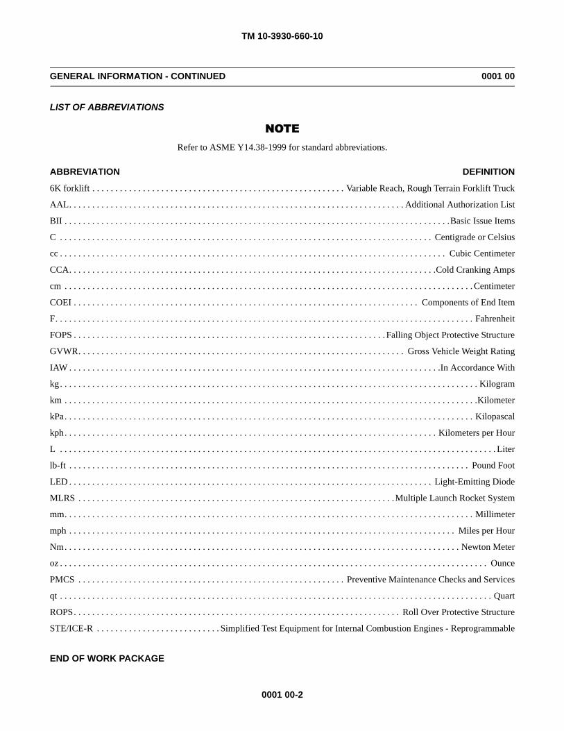
NOTERefer to ASME Y14.38-1999 for standard abbreviations.
ABBREVIATION DEFINITION
6K forklift . . . . . . . . . . . . . . . . . . . . . . . . . . . . . . . . . . . . . . . . . . . . . . . . . . . . . . . Variable Reach, Rough Terrain Forklift Truck
AAL. . . . . . . . . . . . . . . . . . . . . . . . . . . . . . . . . . . . . . . . . . . . . . . . . . . . . . . . . . . . . . . . . . . . . . . . . Additional Authorization List
BII . . . . . . . . . . . . . . . . . . . . . . . . . . . . . . . . . . . . . . . . . . . . . . . . . . . . . . . . . . . . . . . . . . . . . . . . . . . . . . . . . . . .Basic Issue Items
C . . . . . . . . . . . . . . . . . . . . . . . . . . . . . . . . . . . . . . . . . . . . . . . . . . . . . . . . . . . . . . . . . . . . . . . . . . . . . . . . . Centigrade or Celsius
cc . . . . . . . . . . . . . . . . . . . . . . . . . . . . . . . . . . . . . . . . . . . . . . . . . . . . . . . . . . . . . . . . . . . . . . . . . . . . . . . . . . . . Cubic Centimeter
CCA. . . . . . . . . . . . . . . . . . . . . . . . . . . . . . . . . . . . . . . . . . . . . . . . . . . . . . . . . . . . . . . . . . . . . . . . . . . . . . . .Cold Cranking Amps
cm . . . . . . . . . . . . . . . . . . . . . . . . . . . . . . . . . . . . . . . . . . . . . . . . . . . . . . . . . . . . . . . . . . . . . . . . . . . . . . . . . . . . . . . . . Centimeter
COEI . . . . . . . . . . . . . . . . . . . . . . . . . . . . . . . . . . . . . . . . . . . . . . . . . . . . . . . . . . . . . . . . . . . . . . . . . . . Components of End Item
F. . . . . . . . . . . . . . . . . . . . . . . . . . . . . . . . . . . . . . . . . . . . . . . . . . . . . . . . . . . . . . . . . . . . . . . . . . . . . . . . . . . . . . . . . . . Fahrenheit
FOPS . . . . . . . . . . . . . . . . . . . . . . . . . . . . . . . . . . . . . . . . . . . . . . . . . . . . . . . . . . . . . . . . . . . . Falling Object Protective Structure
GVWR. . . . . . . . . . . . . . . . . . . . . . . . . . . . . . . . . . . . . . . . . . . . . . . . . . . . . . . . . . . . . . . . . . . . . . . Gross Vehicle Weight Rating
IAW . . . . . . . . . . . . . . . . . . . . . . . . . . . . . . . . . . . . . . . . . . . . . . . . . . . . . . . . . . . . . . . . . . . . . . . . . . . . . . . . .In Accordance With
kg. . . . . . . . . . . . . . . . . . . . . . . . . . . . . . . . . . . . . . . . . . . . . . . . . . . . . . . . . . . . . . . . . . . . . . . . . . . . . . . . . . . . . . . . . . . Kilogram
km . . . . . . . . . . . . . . . . . . . . . . . . . . . . . . . . . . . . . . . . . . . . . . . . . . . . . . . . . . . . . . . . . . . . . . . . . . . . . . . . . . . . . . . . . .Kilometer
kPa. . . . . . . . . . . . . . . . . . . . . . . . . . . . . . . . . . . . . . . . . . . . . . . . . . . . . . . . . . . . . . . . . . . . . . . . . . . . . . . . . . . . . . . . . Kilopascal
kph. . . . . . . . . . . . . . . . . . . . . . . . . . . . . . . . . . . . . . . . . . . . . . . . . . . . . . . . . . . . . . . . . . . . . . . . . . . . . . . . . Kilometers per Hour
L . . . . . . . . . . . . . . . . . . . . . . . . . . . . . . . . . . . . . . . . . . . . . . . . . . . . . . . . . . . . . . . . . . . . . . . . . . . . . . . . . . . . . . . . . . . . . . . Liter
lb-ft . . . . . . . . . . . . . . . . . . . . . . . . . . . . . . . . . . . . . . . . . . . . . . . . . . . . . . . . . . . . . . . . . . . . . . . . . . . . . . . . . . . . . . . Pound Foot
LED . . . . . . . . . . . . . . . . . . . . . . . . . . . . . . . . . . . . . . . . . . . . . . . . . . . . . . . . . . . . . . . . . . . . . . . . . . . . . . . Light-Emitting Diode
MLRS . . . . . . . . . . . . . . . . . . . . . . . . . . . . . . . . . . . . . . . . . . . . . . . . . . . . . . . . . . . . . . . . . . . . .Multiple Launch Rocket System
mm. . . . . . . . . . . . . . . . . . . . . . . . . . . . . . . . . . . . . . . . . . . . . . . . . . . . . . . . . . . . . . . . . . . . . . . . . . . . . . . . . . . . . . . . . Millimeter
mph . . . . . . . . . . . . . . . . . . . . . . . . . . . . . . . . . . . . . . . . . . . . . . . . . . . . . . . . . . . . . . . . . . . . . . . . . . . . . . . . . . . . Miles per Hour
Nm. . . . . . . . . . . . . . . . . . . . . . . . . . . . . . . . . . . . . . . . . . . . . . . . . . . . . . . . . . . . . . . . . . . . . . . . . . . . . . . . . . . . . . Newton Meter
oz . . . . . . . . . . . . . . . . . . . . . . . . . . . . . . . . . . . . . . . . . . . . . . . . . . . . . . . . . . . . . . . . . . . . . . . . . . . . . . . . . . . . . . . . . . . . . Ounce
PMCS . . . . . . . . . . . . . . . . . . . . . . . . . . . . . . . . . . . . . . . . . . . . . . . . . . . . . . . . . . Preventive Maintenance Checks and Services
qt . . . . . . . . . . . . . . . . . . . . . . . . . . . . . . . . . . . . . . . . . . . . . . . . . . . . . . . . . . . . . . . . . . . . . . . . . . . . . . . . . . . . . . . . . . . . . . Quart
ROPS. . . . . . . . . . . . . . . . . . . . . . . . . . . . . . . . . . . . . . . . . . . . . . . . . . . . . . . . . . . . . . . . . . . . . . . Roll Over Protective Structure
STE/ICE-R . . . . . . . . . . . . . . . . . . . . . . . . . . . Simplified Test Equipment for Internal Combustion Engines - Reprogrammable
END OF WORK PACKAGE
TM 10-3930-660-10
0002 00-1
EQUIPMENT DESCRIPTION AND DATA 0002 00
EQUIPMENT CHARACTERISTICS, CAPABILITIES AND FEATURES
1. Characteristics. All weather operational.
2. Capabilities and Features. a. With the MLRS lifting tool and stop tube on the forks, the vehicle can handle MLRS pods. b. With the MLRS lifting tool and stop tube removed and the backrest installed on carriage, the vehicle can han-
dle boxes and palletized ammunition loads.c. The lifting tool stop tube fits over the forks. It prevents the lifting tool from moving too far back on the forks and
prevents the MLRS pods from contacting the frame or vehicle wheels when in the carry position.d. The vehicle frame can be tilted 9 degrees to left or right which allows vehicle to be level when traversing a
sideslope.e. The MLRS attachment can be raised to a horizontal position for loading and unloading munitions.f. The forks tilt, level, and sideshift to maneuver loads.g. Lifts loads of 6,000 lb (2,722 kg) to a height of 23 ft (7 m) and 4,000 lb (1,814 kg) to a height of 26 ft (8 m).h. Can tow other vehicles weighing 27,100 lb (12,292 kg) or less.i. The operator can select one of three steering modes: two steer, four steer, and crab steer.j. Can ford in up to 30 in. (762 mm) of water.

TM 10-3930-660-10
0002 00-2
EQUIPMENT DESCRIPTION AND DATA - CONTINUED 0002 00
LOCATION AND DESCRIPTION OF MAJOR COMPONENTS
KEY COMPONENT DESCRIPTION
1 Radiator Contains coolant which provides engine cooling.
2 Boom Hoist Cylinder Raises and lowers the boom.
3 Lifting Hook and StopAssembly (shown in storageposition)
The stop tube prevents the lifting hook from moving too far back onthe forks and prevents the MLRS pod from contacting the frame orvehicle wheels when in the carry position.
4 Attachment The attachment can be raised to a horizontal position, creating a lowprofile and extended reach configuration. This configuration isuseful in loading and unloading munitions from transport vehicles andcontainers.
5 Fuel Tank Contains diesel fuel for engine operation.
6 Hydraulic Oil Reservoir Contains hydraulic oil for the hydraulic system.
7 Frame and Counterweight The frame is a heavy-duty design constructed of 1-3/16 in. thick steelplates. The frame is equipped with tie-down lugs meeting air transportspecifications, tow lugs, a pintle hook, and a 3,600 lb counterweight.
8 Load Backrest (shown instorage position)
Used to rest a load during non-MLRS operations. The backrest can beattached to the fork carriage and serves as a backstop or supportmaterials being carried on the forks.
409-001
1 23
4
56
7
8
TM 10-3930-660-10
0002 00-3
EQUIPMENT DESCRIPTION AND DATA - CONTINUED 0002 00
LOCATION AND DESCRIPTION OF MAJOR COMPONENTS - CONTINUED
KEY COMPONENT DESCRIPTION
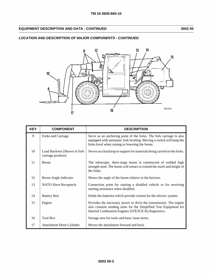
9 Forks and Carriage Serve as an anchoring point of the forks. The fork carriage is alsoequipped with automatic fork leveling. Moving a switch will keep theforks level when raising or lowering the boom.
10 Load Backrest (Shown in forkcarriage position)
Serves as a backstop or support for materials being carried on the forks.
11 Boom The telescopic, three-stage boom is constructed of welded highstrength steel. The boom will retract or extend the reach and height ofthe forks.
12 Boom Angle Indicator Shows the angle of the boom relative to the horizon.
13 NATO Slave Receptacle Connection point for starting a disabled vehicle or for receivingstarting assistance when disabled.
14 Battery Box Holds the batteries which provide current for the electric system.
15 Engine Provides the necessary power to drive the transmission. The enginealso contains sending units for the Simplified Test Equipment forInternal Combustion Engines (STE/ICE-R) diagnostics.
16 Tool Box Storage area for tools and basic issue items.
17 Attachment Hoist Cylinder Moves the attachment forward and back.
409-002
9
10
17
14
16
13121115
TM 10-3930-660-10
0002 00-4
EQUIPMENT DESCRIPTION AND DATA - CONTINUED 0002 00
EQUIPMENT DATA
General:
Type . . . . . . . . . . . . . . . . . . . . . . . . . . . . . . . . . . . . . . . . . . . . . . . Truck, Forklift, 6,000 lb; Variable Reach, Rough Terrain
Vehicle Operational Weight . . . . . . . . . . . . . . . . . . . . . . . . . . . . . . . . . . . . . . . . . . . . . . . . . . . . . . . . . 27,100 lb (12,292 kg)
Boom Assembly Weight . . . . . . . . . . . . . . . . . . . . . . . . . . . . . . . . . . . . . . . . . . . . . . . . . . . . . . . . . . . . . 4,100 lb (1,860 kg)
Inner Boom Weight . . . . . . . . . . . . . . . . . . . . . . . . . . . . . . . . . . . . . . . . . . . . . . . . . . . . . . . . . . . . . . . . . . . . 955 lb (433 kg)
Intermediate Boom Weight . . . . . . . . . . . . . . . . . . . . . . . . . . . . . . . . . . . . . . . . . . . . . . . . . . . . . . . . . . . . . . 830 lb (376 kg)
Outer Boom Weight . . . . . . . . . . . . . . . . . . . . . . . . . . . . . . . . . . . . . . . . . . . . . . . . . . . . . . . . . . . . . . . . . . . 1,580 lb (717 kg)
Boom Extend Cylinder Weight . . . . . . . . . . . . . . . . . . . . . . . . . . . . . . . . . . . . . . . . . . . . . . . . . . . . . . . . . . . 537 lb (244 kg)
Length (Carry Position) Maximum . . . . . . . . . . . . . . . . . . . . . . . . . . . . . . . . . . . . . . . . . . . . . . . . . . . . . 312 in. (7,925 mm)
Width . . . . . . . . . . . . . . . . . . . . . . . . . . . . . . . . . . . . . . . . . . . . . . . . . . . . . . . . . . . . . . . . . . . . . . . . . . . . 102 in. (2,591 mm)
Height (Maximum) . . . . . . . . . . . . . . . . . . . . . . . . . . . . . . . . . . . . . . . . . . . . . . . . . . . . . . . . . . . . . . . . . 101 in. (2,565 mm)
Wheelbase . . . . . . . . . . . . . . . . . . . . . . . . . . . . . . . . . . . . . . . . . . . . . . . . . . . . . . . . . . . . . . . . . . . . . . . . 124 in. (3,150 mm)
Track Width (Tread). . . . . . . . . . . . . . . . . . . . . . . . . . . . . . . . . . . . . . . . . . . . . . . . . . . . . . . . . . . . . . . . .81.3 in. (2,065 mm)
Functional:
Lift (Maximum) . . . . . . . . . . . . . . . . . . . . . . . . . . . . . . . . . . . . . . . . . . . . . . . . . . . . . . . . . . . . . . . . . . . . 6,000 lb (2,722 kg)
Lift Height . . . . . . . . . . . . . . . . . . . . . . . . . . . . . . . . . . . . . . . . . . . . . . . . . . . . . . . . . . . . . . . . . . . . . . . . . . . . . . . 26 ft (8 m)
Boom Lift Angle (Maximum) . . . . . . . . . . . . . . . . . . . . . . . . . . . . . . . . . . . . . . . . . . . . . . . . . . . . . . . . . . . . . . . . 45 degrees
Maximum Reach from Load Center to Front Tires . . . . . . . . . . . . . . . . . . . . . . . . . . . . . . . . . . . . . . . . . . . 24.16 ft (7.36 m)
Maximum Reach Below Grade . . . . . . . . . . . . . . . . . . . . . . . . . . . . . . . . . . . . . . . . . . . . . . . . . . . . . . . . . . 20 in. (508 mm)
Ground Clearance . . . . . . . . . . . . . . . . . . . . . . . . . . . . . . . . . . . . . . . . . . . . . . . . . . . . . . . . . . . . . . . . . . . 14.3 in. (363 mm)
Turning Radius (Curb to Curb) . . . . . . . . . . . . . . . . . . . . . . . . . . . . . . . . . . . . . . . . . . . . . . . . . . . . . . . . . 15 ft 4 in. (4.7 m)
Frame Oscillation. . . . . . . . . . . . . . . . . . . . . . . . . . . . . . . . . . . . . . . . . . . . . . . . . . . . . . . . . . . . 9 degrees to the left or right
Fording Depth (Freshwater). . . . . . . . . . . . . . . . . . . . . . . . . . . . . . . . . . . . . . . . . . . . . . . . . . . . . . . . . . . . . 30 in. (762 mm)
Travel Speed (Maximum) . . . . . . . . . . . . . . . . . . . . . . . . . . . . . . . . . . . . . . . . . . . . . . . . . . . . . . . . . . . . . . 23 mph (37 kph)
Refill Capacities:
Fuel Tank . . . . . . . . . . . . . . . . . . . . . . . . . . . . . . . . . . . . . . . . . . . . . . . . . . . . . . . . . . . . . . . . . . . . . . . . . . . 44 gal. (166.5 L)
Cooling System . . . . . . . . . . . . . . . . . . . . . . . . . . . . . . . . . . . . . . . . . . . . . . . . . . . . . . . . . . . . . . . . . . . . . . . . . .8 gal. (30 L)
Hydraulic Oil Reservoir . . . . . . . . . . . . . . . . . . . . . . . . . . . . . . . . . . . . . . . . . . . . . . . . . . . . . . . . . . . . . . .56.6 gal. (214.2 L)
Engine Crankcase. . . . . . . . . . . . . . . . . . . . . . . . . . . . . . . . . . . . . . . . . . . . . . . . . . . . . . . . . . . . . . . . . . . . . . . . . 15 qt (14 L)
Transmission . . . . . . . . . . . . . . . . . . . . . . . . . . . . . . . . . . . . . . . . . . . . . . . . . . . . . . . . . . . . . . . . . . . . . . . . . . . 5.5 gal. (2 L)
TM 10-3930-660-10
0002 00-5/(-6 Blank)
EQUIPMENT DESCRIPTION AND DATA - CONTINUED 0002 00
EQUIPMENT DATA - CONTINUED
Power Train:
Engine (6K):
Model . . . . . . . . . . . . . . . . . . . . . . . . . . . . . . . . . . . . . . . . . . . . . . . . . . . . . . . . . . . . . . . . . . . . . . . . . . . . . . . . . . . .6BT5.9
Manufacturer . . . . . . . . . . . . . . . . . . . . . . . . . . . . . . . . . . . . . . . . . . . . . . . . . . . . . . . . . . . . . . . . . . . . . . . . . . . . . Cummins
Horsepower (@ 2,500 RPM) . . . . . . . . . . . . . . . . . . . . . . . . . . . . . . . . . . . . . . . . . . . . . . . . . . . . . . . . . . . . . . . . . . 152 hp
Number of Cylinders. . . . . . . . . . . . . . . . . . . . . . . . . . . . . . . . . . . . . . . . . . . . . . . . . . . . . . . . . . . . . . . . . . . . . . . . . . . . . .6
Displacement. . . . . . . . . . . . . . . . . . . . . . . . . . . . . . . . . . . . . . . . . . . . . . . . . . . . . . . . . . . . . . . . . . . . . . . . . . . . . . 359 in.3
Weight . . . . . . . . . . . . . . . . . . . . . . . . . . . . . . . . . . . . . . . . . . . . . . . . . . . . . . . . . . . . . . . . . . . . . . . . . . . . 1,075 lb (401 kg)
Engine Idle RPM. . . . . . . . . . . . . . . . . . . . . . . . . . . . . . . . . . . . . . . . . . . . . . . . . . . . . . . . . . . . . . . . . . . . 850 to 950 RPM
Engine (ATLAS):
Model . . . . . . . . . . . . . . . . . . . . . . . . . . . . . . . . . . . . . . . . . . . . . . . . . . . . . . . . . . . . . . . . . . . . . . . . . . . . . . .6BT5.9-C165
Manufacturer . . . . . . . . . . . . . . . . . . . . . . . . . . . . . . . . . . . . . . . . . . . . . . . . . . . . . . . . . . . . . . . . . . . . . . . . . . . . . Cummins
Horsepower (@ 2,500 RPM) . . . . . . . . . . . . . . . . . . . . . . . . . . . . . . . . . . . . . . . . . . . . . . . . . . . . . . . . . . . . . . . . . . 165 hp
Number of Cylinders. . . . . . . . . . . . . . . . . . . . . . . . . . . . . . . . . . . . . . . . . . . . . . . . . . . . . . . . . . . . . . . . . . . . . . . . . . . . . .6
Displacement. . . . . . . . . . . . . . . . . . . . . . . . . . . . . . . . . . . . . . . . . . . . . . . . . . . . . . . . . . . . . . . . . . . . . . . . . . . . . . 359 in.3
Weight . . . . . . . . . . . . . . . . . . . . . . . . . . . . . . . . . . . . . . . . . . . . . . . . . . . . . . . . . . . . . . . . . . . . . . . . . . . . . 930 lb (422 kg)
Engine Idle RPM. . . . . . . . . . . . . . . . . . . . . . . . . . . . . . . . . . . . . . . . . . . . . . . . . . . . . . . . . . . . . . . . . . . 900 to 1,000 RPM
Transmission:
Model . . . . . . . . . . . . . . . . . . . . . . . . . . . . . . . . . . . . . . . . . . . . . . . . . . . . . . . . . . . . . . . . . . . . . . . . . . . . . . . . . . . . . 1,723
Manufacturer . . . . . . . . . . . . . . . . . . . . . . . . . . . . . . . . . . . . . . . . . . . . . . . . . . . . . . . . . . . . . . . . . . . . Funk Manufacturing
Powershift . . . . . . . . . . . . . . . . . . . . . . . . . . . . . . . . . . . . . . . . . . . . . . . . . . . . . . . . . . . . . . . . 3 speed forward and reverse
Speed Range, First Gear . . . . . . . . . . . . . . . . . . . . . . . . . . . . . . . . . . . . . . . . . . . . . . . . . . 0-4 mph (0-6 kph), level surface
Speed Range, Second Gear . . . . . . . . . . . . . . . . . . . . . . . . . . . . . . . . . . . . . . . . . . . . . . . 0-8 mph (0-13 kph), level surface
Speed Range, Third Gear . . . . . . . . . . . . . . . . . . . . . . . . . . . . . . . . . . . . . . . . . . . . . . . 0-23 mph (0-37 kph), level surface
Weight . . . . . . . . . . . . . . . . . . . . . . . . . . . . . . . . . . . . . . . . . . . . . . . . . . . . . . . . . . . . . . . . . . . . . . . . . . . . . 846 lb (384 kg)
Axles and Brakes:
Model (Front) . . . . . . . . . . . . . . . . . . . . . . . . . . . . . . . . . . . . . . . . . . . . . . . . . . . . . . . . . . . . . . . . . . . . PSOC-205-HOB-205
Model (Rear) . . . . . . . . . . . . . . . . . . . . . . . . . . . . . . . . . . . . . . . . . . . . . . . . . . . . . . . . . . . . . . . . . . . . PSOC-205-HOB-206
Manufacturer . . . . . . . . . . . . . . . . . . . . . . . . . . . . . . . . . . . . . . . . . . . . . . . . . . . . . . . . . . . . . . . . . . . . . . . . . . . . . . Rockwell
Weight - Axle Assembly (Front or Rear) . . . . . . . . . . . . . . . . . . . . . . . . . . . . . . . . . . . . . . . . . . . . . . . . . . . 1,650 lb (748 kg)
END OF WORK PACKAGE

TM 10-3930-660-10
0003 00-1
THEORY OF OPERATION 0003 00
INTRODUCTION
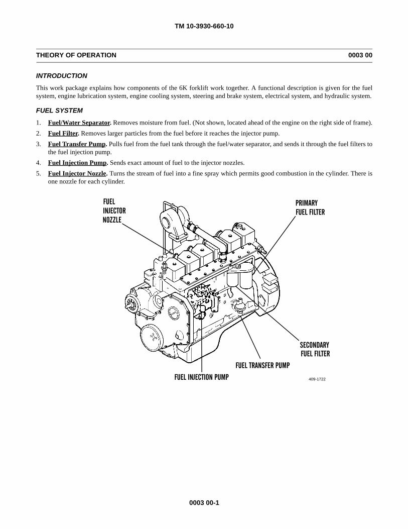
This work package explains how components of the 6K forklift work together. A functional description is given for the fuelsystem, engine lubrication system, engine cooling system, steering and brake system, electrical system, and hydraulic system.
FUEL SYSTEM
1. Fuel/Water Separator. Removes moisture from fuel. (Not shown, located ahead of the engine on the right side of frame).2. Fuel Filter. Removes larger particles from the fuel before it reaches the injector pump.3. Fuel Transfer Pump. Pulls fuel from the fuel tank through the fuel/water separator, and sends it through the fuel filters to
the fuel injection pump.4. Fuel Injection Pump. Sends exact amount of fuel to the injector nozzles.5. Fuel Injector Nozzle. Turns the stream of fuel into a fine spray which permits good combustion in the cylinder. There is
one nozzle for each cylinder.
409-1722
PRIMARY FUEL FILTER
SECONDARYFUEL FILTER
FUEL TRANSFER PUMP
FUEL INJECTION PUMP
FUELINJECTORNOZZLE
TM 10-3930-660-10
0003 00-2
THEORY OF OPERATION - CONTINUED 0003 00
ENGINE LUBRICATION AND COOLING SYSTEMS
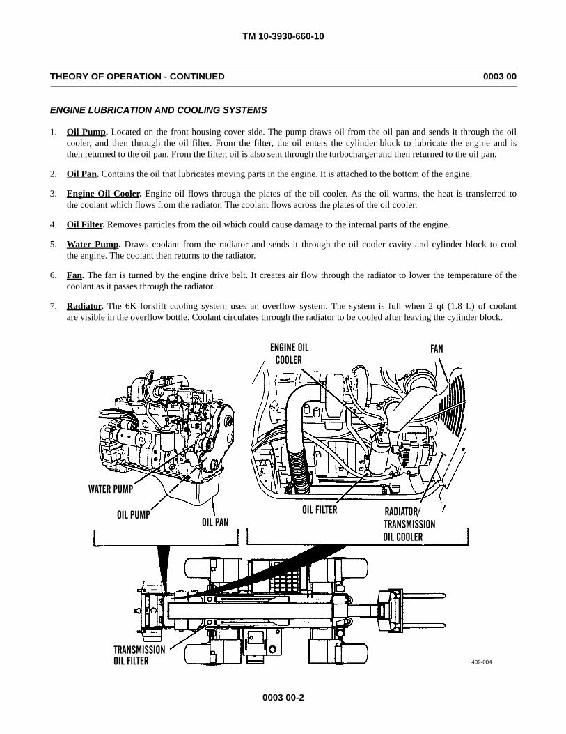
1. Oil Pump. Located on the front housing cover side. The pump draws oil from the oil pan and sends it through the oilcooler, and then through the oil filter. From the filter, the oil enters the cylinder block to lubricate the engine and isthen returned to the oil pan. From the filter, oil is also sent through the turbocharger and then returned to the oil pan.
2. Oil Pan. Contains the oil that lubricates moving parts in the engine. It is attached to the bottom of the engine.
3. Engine Oil Cooler. Engine oil flows through the plates of the oil cooler. As the oil warms, the heat is transferred tothe coolant which flows from the radiator. The coolant flows across the plates of the oil cooler.
4. Oil Filter. Removes particles from the oil which could cause damage to the internal parts of the engine.
5. Water Pump. Draws coolant from the radiator and sends it through the oil cooler cavity and cylinder block to coolthe engine. The coolant then returns to the radiator.
6. Fan. The fan is turned by the engine drive belt. It creates air flow through the radiator to lower the temperature of thecoolant as it passes through the radiator.
7. Radiator. The 6K forklift cooling system uses an overflow system. The system is full when 2 qt (1.8 L) of coolantare visible in the overflow bottle. Coolant circulates through the radiator to be cooled after leaving the cylinder block.
409-004
FAN
RADIATOR/TRANSMISSIONOIL COOLER
OIL FILTER
ENGINE OILCOOLER
OIL PANOIL PUMP
WATER PUMP
TRANSMISSIONOIL FILTER
TM 10-3930-660-10
0003 00-3
THEORY OF OPERATION - CONTINUED 0003 00
TRANSMISSION LUBRICATION AND COOLING SYSTEMS
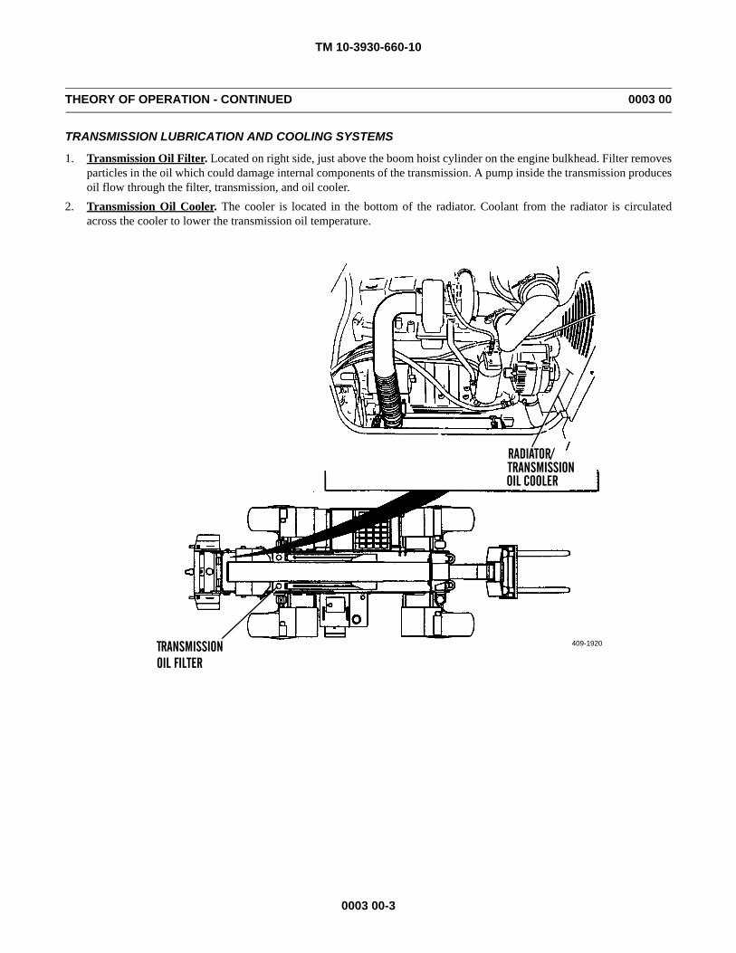
1. Transmission Oil Filter. Located on right side, just above the boom hoist cylinder on the engine bulkhead. Filter removesparticles in the oil which could damage internal components of the transmission. A pump inside the transmission producesoil flow through the filter, transmission, and oil cooler.
2. Transmission Oil Cooler. The cooler is located in the bottom of the radiator. Coolant from the radiator is circulatedacross the cooler to lower the transmission oil temperature.
409-1920
RADIATOR/TRANSMISSIONOIL COOLER
TRANSMISSIONOIL FILTER
TM 10-3930-660-10
0003 00-4
THEORY OF OPERATION - CONTINUED 0003 00
STEERING AND BRAKE SYSTEM
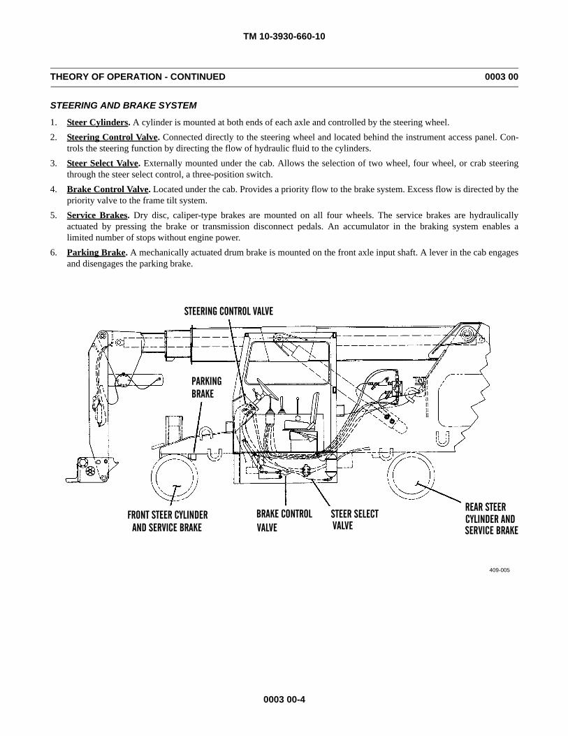
1. Steer Cylinders. A cylinder is mounted at both ends of each axle and controlled by the steering wheel.2. Steering Control Valve. Connected directly to the steering wheel and located behind the instrument access panel. Con-
trols the steering function by directing the flow of hydraulic fluid to the cylinders.3. Steer Select Valve. Externally mounted under the cab. Allows the selection of two wheel, four wheel, or crab steering
through the steer select control, a three-position switch.4. Brake Control Valve. Located under the cab. Provides a priority flow to the brake system. Excess flow is directed by the
priority valve to the frame tilt system.5. Service Brakes. Dry disc, caliper-type brakes are mounted on all four wheels. The service brakes are hydraulically
actuated by pressing the brake or transmission disconnect pedals. An accumulator in the braking system enables alimited number of stops without engine power.
6. Parking Brake. A mechanically actuated drum brake is mounted on the front axle input shaft. A lever in the cab engagesand disengages the parking brake.
409-005
STEERING CONTROL VALVE
FRONT STEER CYLINDERAND SERVICE BRAKE
BRAKE CONTROL VALVE
STEER SELECTVALVE
REAR STEER
SERVICE BRAKE
BRAKEPARKING
CYLINDER AND
TM 10-3930-660-10
0003 00-5
THEORY OF OPERATION - CONTINUED 0003 00
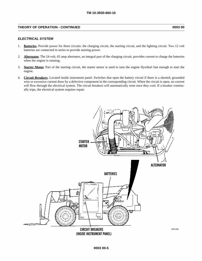
ELECTRICAL SYSTEM
1. Batteries. Provide power for three circuits: the charging circuit, the starting circuit, and the lighting circuit. Two 12 voltbatteries are connected in series to provide starting power.
2. Alternator. The 24 volt, 65 amp alternator, an integral part of the charging circuit, provides current to charge the batterieswhen the engine is running.
3. Starter Motor. Part of the starting circuit, the starter motor is used to turn the engine flywheel fast enough to start theengine.
4. Circuit Breakers. Located inside instrument panel. Switches that open the battery circuit if there is a shorted, groundedwire or excessive current draw by a defective component in the corresponding circuit. When the circuit is open, no currentwill flow through the electrical system. The circuit breakers will automatically reset once they cool. If a breaker continu-ally trips, the electrical system requires repair.
409-006
STARTERMOTOR
ALTERNATOR
BATTERIES
CIRCUIT BREAKERS(INSIDE INSTRUMENT PANEL)
TM 10-3930-660-10
0003 00-6
THEORY OF OPERATION - CONTINUED 0003 00
HYDRAULIC SYSTEM
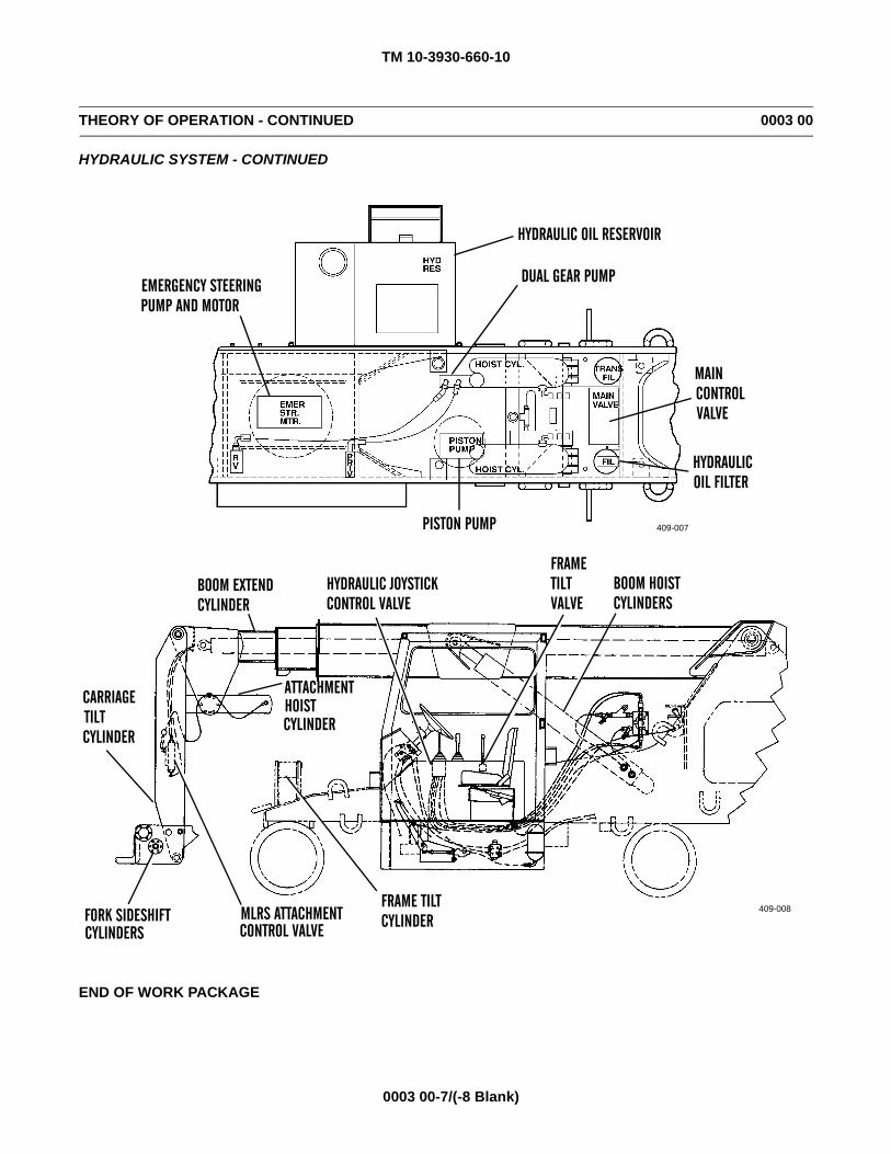
1. Hydraulic Oil Reservoir. Contains oil for the entire hydraulic system.
2. Hydraulic Oil Filter. Removes smaller harmful particles from the oil before the oil returns to the reservoir.
3. Main Control Valve. Located on the engine compartment bulkhead of the main frame (near back of transmission). Oper-ated by the hydraulic joystick control valve to control: boom hoist/lowering and extend/retract.
4. Attachment Control Valve. Mounted on the attachment and controlled by an electrical joystick. Controls the threeattachment functions: hoist/lowering, fork tilt, and fork sideshift.
5. Frame Tilt Valve. Mounted inside the console located to the right of the operator seat. Controls the tilting of the vehicleframe. Operated by frame tilt control lever.
6. Hydraulic Joystick Control Valve. Located on the side console in cab. Controls the following boom functions: raise,lower, extend, and retract.
7. Dual Gear Pump. Mounted to and driven by the transmission to supply hydraulic oil flow. This two section pump sup-plies hydraulic fluid for the following functions: boom hoist, boom extend, steering, brakes and frame tilt.
8. Piston Pump. Mounted to and driven by the transmission. This pump supplies hydraulic fluid for the following functions:attachment hoist, fork tilt and shift control.
9. Emergency Steering Pump and Motor. Located in the vehicle frame forward of the transmission. This pump supplies 5gpm of emergency flow to the steering system whenever the starter-run control switch is on and there is a loss of hydraulicoil pressure. The pump is driven by an electric motor.
10. Fork Sideshift Cylinders. Two cylinders controlled by one joystick control. Both cylinders can by operated at the sametime to sideshift forks left or right, to move forks together or apart. The cylinders can also be operated individually.
11. Carriage Tilt Cylinders. Two cylinders controlled by the electric joystick control. Moving the lever to the right causesthe cylinders to extend and the fork tips to lower. Moving the lever to the left causes the cylinders to retract and the forktips to raise.
12. Attachment Hoist Cylinder. This cylinder is controlled by the attachment hoist control joystick. When the lever ispushed forward, the cylinder will retract. When the lever is pulled back, the cylinder will extend and raise the MLRSattachment.
13. Boom Extend Cylinder. This cylinder is controlled by the boom extend and retract joystick control. Moving the lever tothe right causes the cylinder to extend and increase the reach distance or the height of the forks, depending on the angle ofthe boom. Moving the lever to the left causes the cylinder to retract.
14. Frame Tilt Cylinder. This cylinder is controlled by the frame tilt control joystick. When the lever is moved forward, thecylinder extends and tilts the vehicle to the left. Pulling the lever back causes the cylinder to retract and tilt the frame tothe right.
15. Boom Hoist Cylinders. Two cylinders controlled by the boom hoist control joystick. When the lever is moved forward,the cylinders retract and the boom lowers. Moving the lever backward causes the cylinders to extend and the boom toraise.
TM 10-3930-660-10
0003 00-7/(-8 Blank)
THEORY OF OPERATION - CONTINUED 0003 00
HYDRAULIC SYSTEM - CONTINUED
END OF WORK PACKAGE
409-007
HYDRAULIC OIL RESERVOIR
DUAL GEAR PUMP
PISTON PUMP
EMERGENCY STEERINGPUMP AND MOTOR
MAINCONTROL VALVE
HYDRAULICOIL FILTER
409-008
HYDRAULIC JOYSTICKBOOM EXTENDFRAME
BOOM HOIST
FRAME TILTMLRS ATTACHMENTFORK SIDESHIFT CONTROL VALVECYLINDERS
ATTACHMENTHOISTCYLINDER
CARRIAGETILTCYLINDER
CYLINDERSCONTROL VALVECYLINDERTILTVALVE
CYLINDER

TM 10-3930-660-10
CHAPTER 2OPERATING INSTRUCTIONS

TM 10-3930-660-10
0004 00-1
DESCRIPTION AND USE OF OPERATOR CONTROLS AND INDICATORS 0004 00
GENERAL
This work package describes, locates and illustrates the controls and indicators used on the 6K forklift. Read and becomefamiliar with the location and function of all operator controls and indicators, as described in this work package.
TM 10-3930-660-10
0004 00-2
DESCRIPTION AND USE OF OPERATOR CONTROLS AND INDICATORS - CONTINUED 0004 00
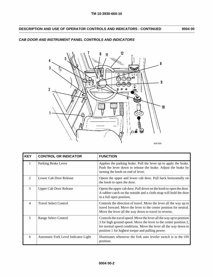
CAB DOOR AND INSTRUMENT PANEL CONTROLS AND INDICATORS
KEY CONTROL OR INDICATOR FUNCTION
1 Parking Brake Lever Applies the parking brake. Pull the lever up to apply the brake.Push the lever down to release the brake. Adjust the brake byturning the knob on end of lever.
2 Lower Cab Door Release Opens the upper and lower cab door. Pull back horizontally onthe knob to open the door.
3 Upper Cab Door Release Opens the upper cab door. Pull down on the knob to open the door.A rubber catch on the outside and a cloth strap will hold the doorin a full open position.
4 Travel Select Control Controls the direction of travel. Move the lever all the way up totravel forward. Move the lever to the center position for neutral.Move the lever all the way down to travel in reverse.
5 Range Select Control Controls the travel speed. Move the lever all the way up to position3 for high ground speed. Move the lever to the center position 2,for normal speed conditions. Move the lever all the way down toposition 1 for highest torque and pulling power.
6 Automatic Fork Level Indicator Light Illuminates whenever the fork auto leveler switch is in the ONposition.
409-009
1
2
3
4 567
8
9
10
11 12
TM 10-3930-660-10
0004 00-3
DESCRIPTION AND USE OF OPERATOR CONTROLS AND INDICATORS - CONTINUED 0004 00
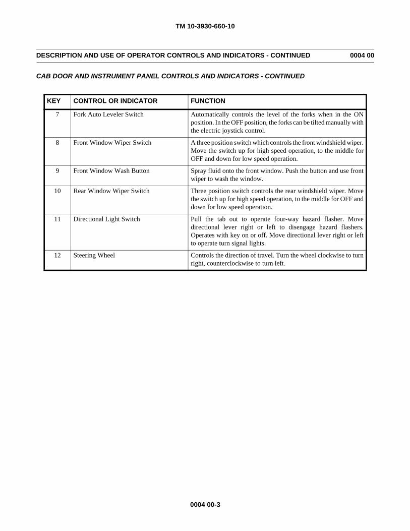
CAB DOOR AND INSTRUMENT PANEL CONTROLS AND INDICATORS - CONTINUED
KEY CONTROL OR INDICATOR FUNCTION
7 Fork Auto Leveler Switch Automatically controls the level of the forks when in the ONposition. In the OFF position, the forks can be tilted manually withthe electric joystick control.
8 Front Window Wiper Switch A three position switch which controls the front windshield wiper.Move the switch up for high speed operation, to the middle forOFF and down for low speed operation.
9 Front Window Wash Button Spray fluid onto the front window. Push the button and use frontwiper to wash the window.
10 Rear Window Wiper Switch Three position switch controls the rear windshield wiper. Movethe switch up for high speed operation, to the middle for OFF anddown for low speed operation.
11 Directional Light Switch Pull the tab out to operate four-way hazard flasher. Movedirectional lever right or left to disengage hazard flashers.Operates with key on or off. Move directional lever right or leftto operate turn signal lights.
12 Steering Wheel Controls the direction of travel. Turn the wheel clockwise to turnright, counterclockwise to turn left.
TM 10-3930-660-10
0004 00-4
DESCRIPTION AND USE OF OPERATOR CONTROLS AND INDICATORS - CONTINUED 0004 00
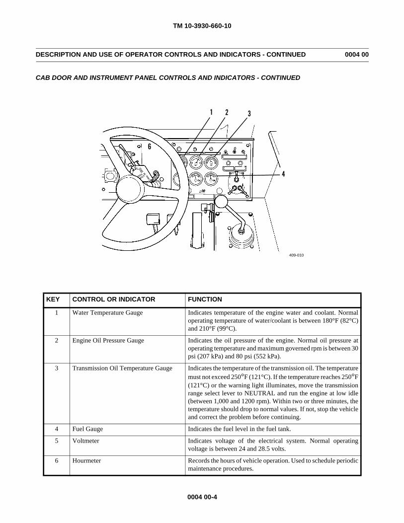
CAB DOOR AND INSTRUMENT PANEL CONTROLS AND INDICATORS - CONTINUED
KEY CONTROL OR INDICATOR FUNCTION
1 Water Temperature Gauge Indicates temperature of the engine water and coolant. Normaloperating temperature of water/coolant is between 180°F (82°C)and 210°F (99°C).
2 Engine Oil Pressure Gauge Indicates the oil pressure of the engine. Normal oil pressure atoperating temperature and maximum governed rpm is between 30psi (207 kPa) and 80 psi (552 kPa).
3 Transmission Oil Temperature Gauge Indicates the temperature of the transmission oil. The temperaturemust not exceed 250°F (121°C). If the temperature reaches 250°F(121°C) or the warning light illuminates, move the transmissionrange select lever to NEUTRAL and run the engine at low idle(between 1,000 and 1200 rpm). Within two or three minutes, thetemperature should drop to normal values. If not, stop the vehicleand correct the problem before continuing.
4 Fuel Gauge Indicates the fuel level in the fuel tank.
5 Voltmeter Indicates voltage of the electrical system. Normal operatingvoltage is between 24 and 28.5 volts.
6 Hourmeter Records the hours of vehicle operation. Used to schedule periodicmaintenance procedures.
1 2 3
4
5
6
409-010
TM 10-3930-660-10
0004 00-5
DESCRIPTION AND USE OF OPERATOR CONTROLS AND INDICATORS - CONTINUED 0004 00
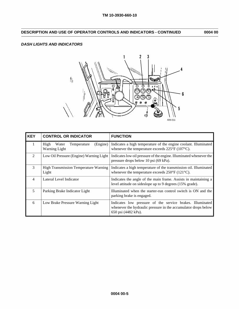
DASH LIGHTS AND INDICATORS
KEY CONTROL OR INDICATOR FUNCTION
1 High Water Temperature (Engine)Warning Light
Indicates a high temperature of the engine coolant. Illuminatedwhenever the temperature exceeds 225°F (107°C).
2 Low Oil Pressure (Engine) Warning Light Indicates low oil pressure of the engine. Illuminated whenever thepressure drops below 10 psi (69 kPa).
3 High Transmission Temperature WarningLight
Indicates a high temperature of the transmission oil. Illuminatedwhenever the temperature exceeds 250°F (121°C).
4 Lateral Level Indicator Indicates the angle of the main frame. Assists in maintaining alevel attitude on sideslope up to 9 degrees (15% grade).
5 Parking Brake Indicator Light Illuminated when the starter-run control switch is ON and theparking brake is engaged.
6 Low Brake Pressure Warning Light Indicates low pressure of the service brakes. Illuminatedwhenever the hydraulic pressure in the accumulator drops below650 psi (4482 kPa).
409-011
1 2 3
4
5
6
TM 10-3930-660-10
0004 00-6
DESCRIPTION AND USE OF OPERATOR CONTROLS AND INDICATORS - CONTINUED 0004 00
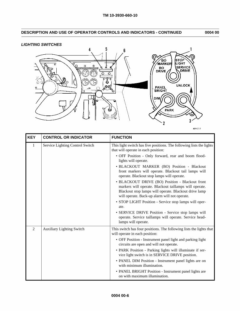
LIGHTING SWITCHES
KEY CONTROL OR INDICATOR FUNCTION
1 Service Lighting Control Switch This light switch has five positions. The following lists the lightsthat will operate in each position:
• OFF Position - Only forward, rear and boom flood-lights will operate.
• BLACKOUT MARKER (BO) Position - Blackoutfront markers will operate. Blackout tail lamps willoperate. Blackout stop lamps will operate.
• BLACKOUT DRIVE (BO) Position - Blackout frontmarkers will operate. Blackout taillamps will operate.Blackout stop lamps will operate. Blackout drive lampwill operate. Back-up alarm will not operate.
• STOP LIGHT Position - Service stop lamps will oper-ate.
• SERVICE DRIVE Position - Service stop lamps willoperate. Service taillamps will operate. Service head-lamps will operate.
2 Auxiliary Lighting Switch This switch has four positions. The following lists the lights thatwill operate in each position:
• OFF Position - Instrument panel light and parking lightcircuits are open and will not operate.
• PARK Position - Parking lights will illuminate if ser-vice light switch is in SERVICE DRIVE position.
• PANEL DIM Position - Instrument panel lights are onwith minimum illumination.
• PANEL BRIGHT Position - Instrument panel lights areon with maximum illumination.
1654
2 3
TM 10-3930-660-10
0004 00-7
DESCRIPTION AND USE OF OPERATOR CONTROLS AND INDICATORS - CONTINUED 0004 00
LIGHTING SWITCHES - CONTINUED
KEY CONTROL OR INDICATOR FUNCTION
3 Switch Lock This lock is used to prevent accidental movement of the mainlighting control switch. Lift lock lever to move service lightingcontrol switch to STOP LIGHT, SERVICE DRIVE and BODRIVE positions.
4 Light Switch (Forward Floods) Controls the forward floodlights.
5 Light Switch (Boom Flood) Controls the boom floodlights.
6 Light Switch (Rear Floods) Controls the rear floodlights.
TM 10-3930-660-10
0004 00-8
DESCRIPTION AND USE OF OPERATOR CONTROLS AND INDICATORS - CONTINUED 0004 00
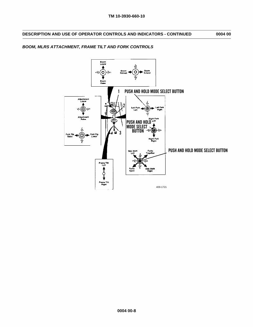
BOOM, MLRS ATTACHMENT, FRAME TILT AND FORK CONTROLS
409-1721
PUSH AND HOLD MODE SELECT BUTTON
PUSH AND HOLD MODE SELECT
BUTTON
1
2
3
PUSH AND HOLD MODE SELECT BUTTON
TM 10-3930-660-10
0004 00-9
DESCRIPTION AND USE OF OPERATOR CONTROLS AND INDICATORS - CONTINUED 0004 00
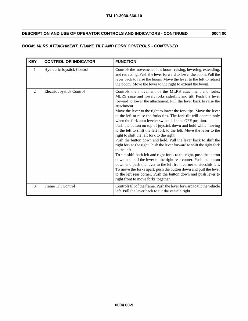
BOOM, MLRS ATTACHMENT, FRAME TILT AND FORK CONTROLS - CONTINUED
KEY CONTROL OR INDICATOR FUNCTION
1 Hydraulic Joystick Control Controls the movement of the boom: raising, lowering, extending,and retracting. Push the lever forward to lower the boom. Pull thelever back to raise the boom. Move the lever to the left to retractthe boom. Move the lever to the right to extend the boom.
2 Electric Joystick Control Controls the movement of the MLRS attachment and forks:MLRS raise and lower, forks sideshift and tilt. Push the leverforward to lower the attachment. Pull the lever back to raise theattachment.Move the lever to the right to lower the fork tips. Move the leverto the left to raise the forks tips. The fork tilt will operate onlywhen the fork auto leveler switch is in the OFF position.Push the button on top of joystick down and hold while movingto the left to shift the left fork to the left. Move the lever to theright to shift the left fork to the right.Push the button down and hold. Pull the lever back to shift theright fork to the right. Push the lever forward to shift the right forkto the left.To sideshift both left and right forks to the right, push the buttondown and pull the lever to the right rear corner. Push the buttondown and push the lever to the left front corner to sideshift left.To move the forks apart, push the button down and pull the leverto the left rear corner. Push the button down and push lever toright front to move forks together.
3 Frame Tilt Control Controls tilt of the frame. Push the lever forward to tilt the vehicleleft. Pull the lever back to tilt the vehicle right.
TM 10-3930-660-10
0004 00-10
DESCRIPTION AND USE OF OPERATOR CONTROLS AND INDICATORS - CONTINUED 0004 00
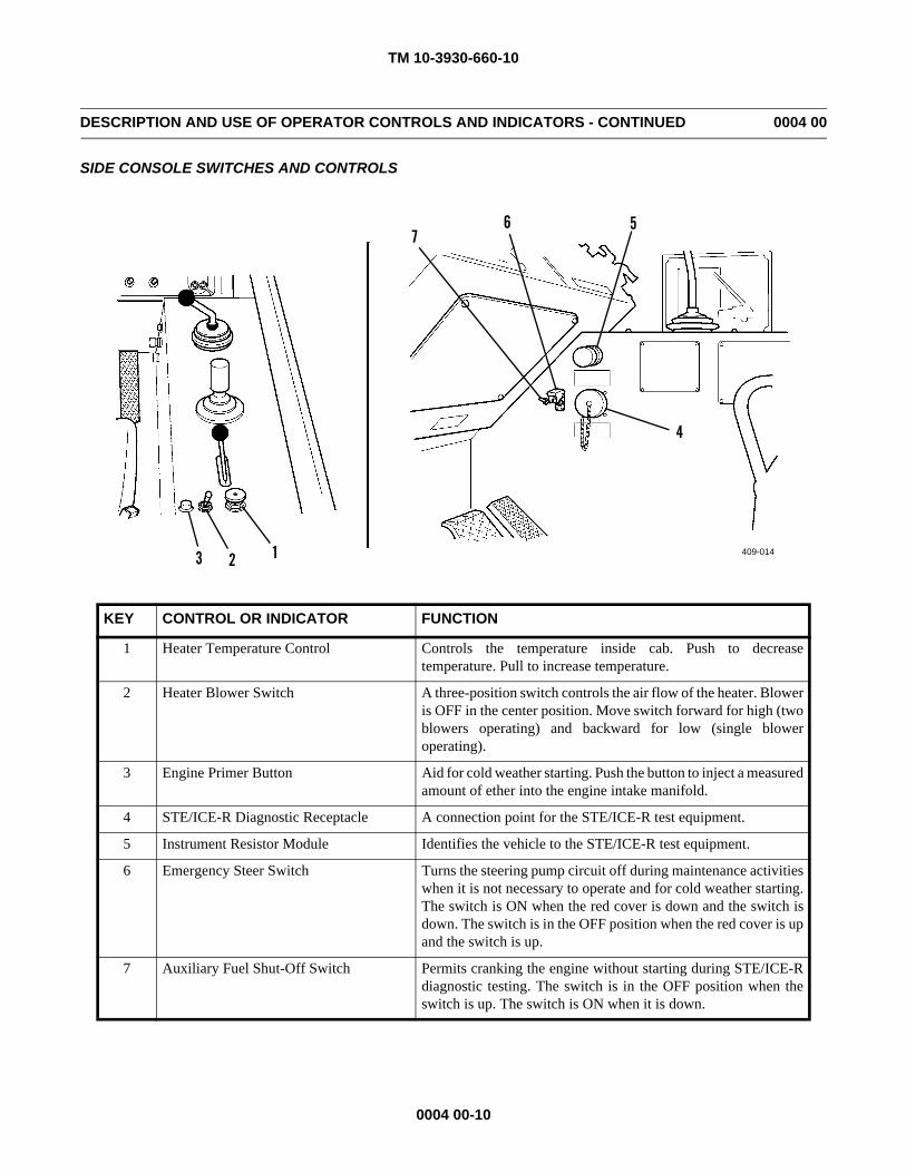
SIDE CONSOLE SWITCHES AND CONTROLS
KEY CONTROL OR INDICATOR FUNCTION
1 Heater Temperature Control Controls the temperature inside cab. Push to decreasetemperature. Pull to increase temperature.
2 Heater Blower Switch A three-position switch controls the air flow of the heater. Bloweris OFF in the center position. Move switch forward for high (twoblowers operating) and backward for low (single bloweroperating).
3 Engine Primer Button Aid for cold weather starting. Push the button to inject a measuredamount of ether into the engine intake manifold.
4 STE/ICE-R Diagnostic Receptacle A connection point for the STE/ICE-R test equipment.
5 Instrument Resistor Module Identifies the vehicle to the STE/ICE-R test equipment.
6 Emergency Steer Switch Turns the steering pump circuit off during maintenance activitieswhen it is not necessary to operate and for cold weather starting.The switch is ON when the red cover is down and the switch isdown. The switch is in the OFF position when the red cover is upand the switch is up.
7 Auxiliary Fuel Shut-Off Switch Permits cranking the engine without starting during STE/ICE-Rdiagnostic testing. The switch is in the OFF position when theswitch is up. The switch is ON when it is down.
409-014123
4
567
TM 10-3930-660-10
0004 00-11
DESCRIPTION AND USE OF OPERATOR CONTROLS AND INDICATORS - CONTINUED 0004 00
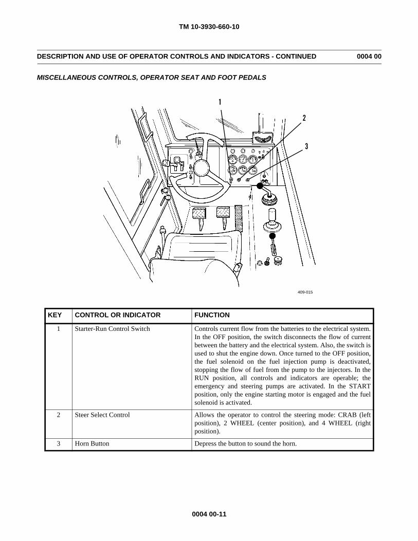
MISCELLANEOUS CONTROLS, OPERATOR SEAT AND FOOT PEDALS
KEY CONTROL OR INDICATOR FUNCTION
1 Starter-Run Control Switch Controls current flow from the batteries to the electrical system.In the OFF position, the switch disconnects the flow of currentbetween the battery and the electrical system. Also, the switch isused to shut the engine down. Once turned to the OFF position,the fuel solenoid on the fuel injection pump is deactivated,stopping the flow of fuel from the pump to the injectors. In theRUN position, all controls and indicators are operable; theemergency and steering pumps are activated. In the STARTposition, only the engine starting motor is engaged and the fuelsolenoid is activated.
2 Steer Select Control Allows the operator to control the steering mode: CRAB (leftposition), 2 WHEEL (center position), and 4 WHEEL (rightposition).
3 Horn Button Depress the button to sound the horn.
409-015
1
2
3
TM 10-3930-660-10
0004 00-12
DESCRIPTION AND USE OF OPERATOR CONTROLS AND INDICATORS - CONTINUED 0004 00
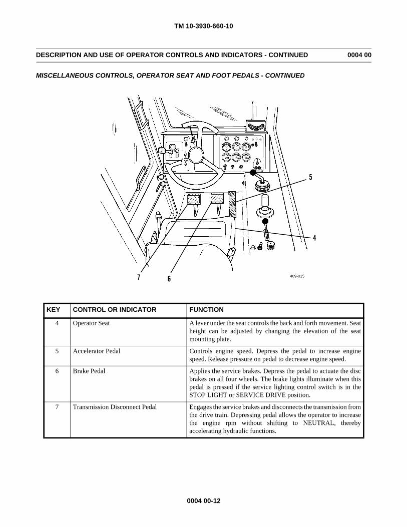
MISCELLANEOUS CONTROLS, OPERATOR SEAT AND FOOT PEDALS - CONTINUED
KEY CONTROL OR INDICATOR FUNCTION
4 Operator Seat A lever under the seat controls the back and forth movement. Seatheight can be adjusted by changing the elevation of the seatmounting plate.
5 Accelerator Pedal Controls engine speed. Depress the pedal to increase enginespeed. Release pressure on pedal to decrease engine speed.
6 Brake Pedal Applies the service brakes. Depress the pedal to actuate the discbrakes on all four wheels. The brake lights illuminate when thispedal is pressed if the service lighting control switch is in theSTOP LIGHT or SERVICE DRIVE position.
7 Transmission Disconnect Pedal Engages the service brakes and disconnects the transmission fromthe drive train. Depressing pedal allows the operator to increasethe engine rpm without shifting to NEUTRAL, therebyaccelerating hydraulic functions.
409-015
4
5
67
TM 10-3930-660-10
0004 00-13
DESCRIPTION AND USE OF OPERATOR CONTROLS AND INDICATORS - CONTINUED 0004 00
MISCELLANEOUS CONTROLS, OPERATOR SEAT AND FOOT PEDALS - CONTINUED
KEY CONTROL OR INDICATOR FUNCTION
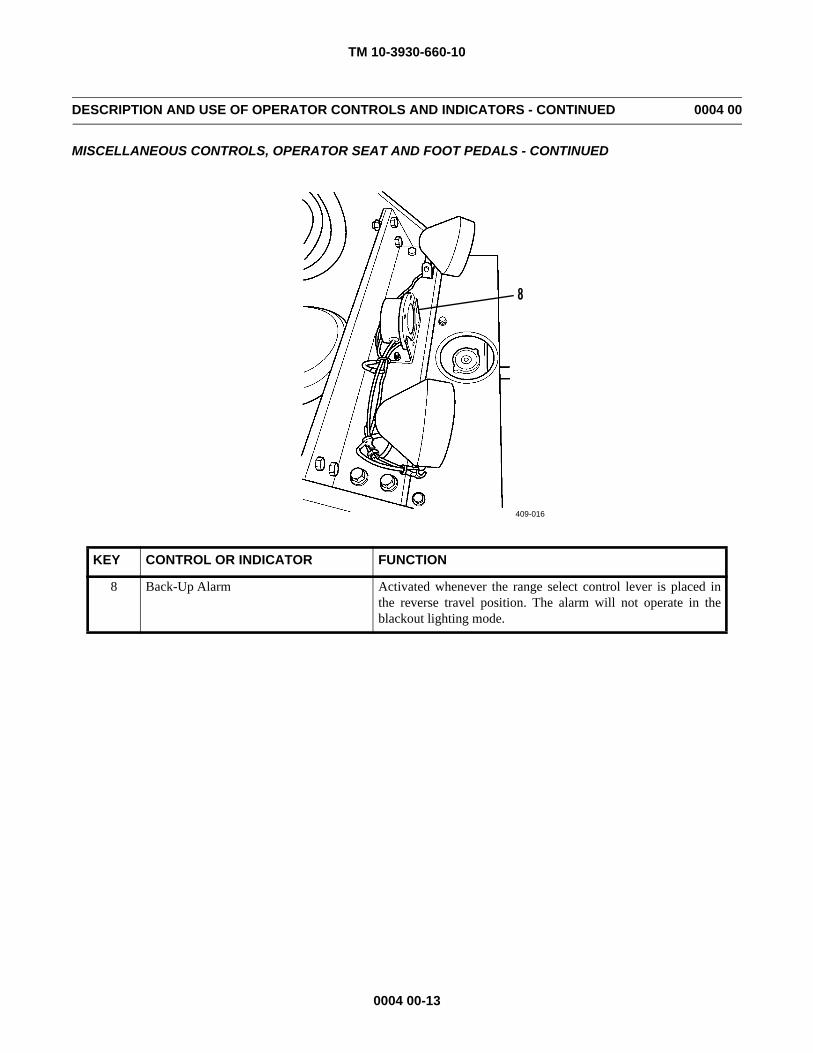
8 Back-Up Alarm Activated whenever the range select control lever is placed inthe reverse travel position. The alarm will not operate in theblackout lighting mode.
409-016
8
TM 10-3930-660-10
0004 00-14
DESCRIPTION AND USE OF OPERATOR CONTROLS AND INDICATORS - CONTINUED 0004 00
MISCELLANEOUS CONTROLS, OPERATOR SEAT AND FOOT PEDALS - CONTINUED
END OF WORK PACKAGE
KEY CONTROL OR INDICATOR FUNCTION
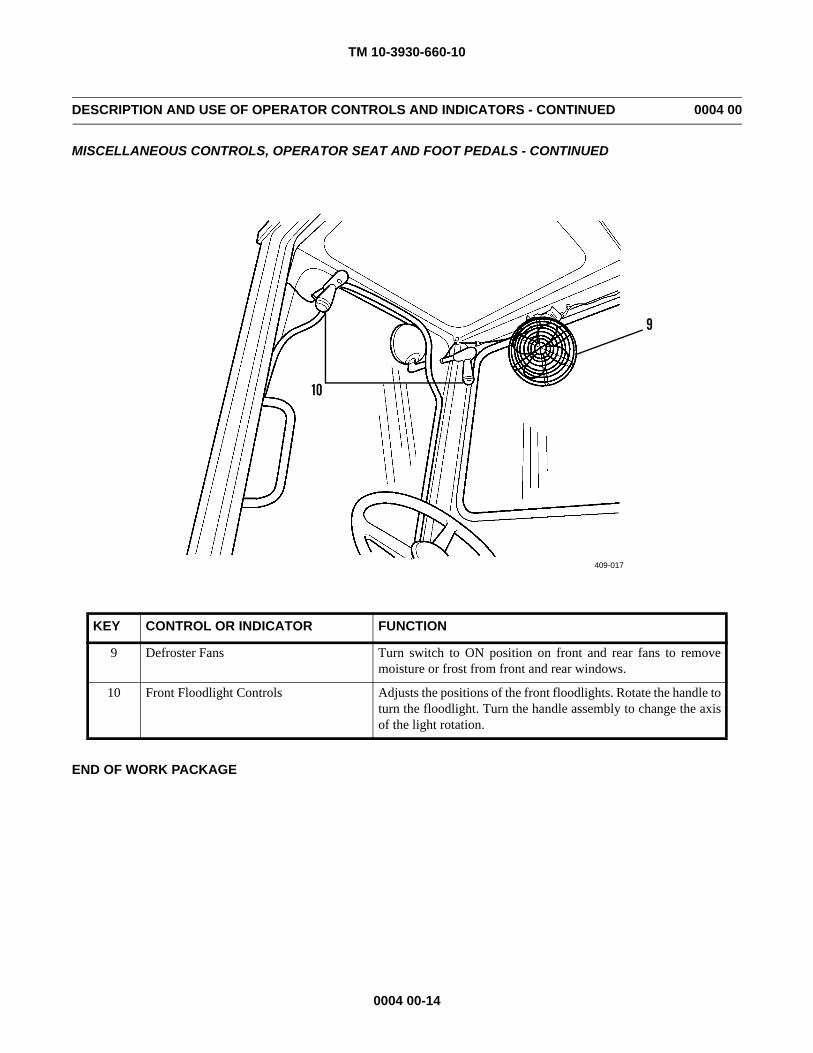
9 Defroster Fans Turn switch to ON position on front and rear fans to removemoisture or frost from front and rear windows.
10 Front Floodlight Controls Adjusts the positions of the front floodlights. Rotate the handle toturn the floodlight. Turn the handle assembly to change the axisof the light rotation.
409-017
9
10
TM 10-3930-660-10
0005 00-1
OPERATION UNDER USUAL CONDITIONS 0005 00
GENERALIt is essential that the operator know how to perform every operation of which the vehicle is capable. This work package
gives instructions on starting and stopping the vehicle, on the basic motions of the vehicle and how to use these instructions toperform specific tasks for which the equipment was designed.
NEW VEHICLE BREAK-IN
Controlled break-in is the ideal fitting of all internal moving metal parts. Using the proper oil and preventive maintenanceprogram during this period will provide long life of the engine.1. Starting the Engine. Warm the engine to operating temperature, 180-190°F (82-88°C), before placing the engine under
load.2. Operation.
a. Avoid constant speeds.b. Use the range select control lever to place the transmission in the appropriate gear to prevent engine lugging.c. Check the gauges to ensure normal operation of the engine.d. Check the coolant level and fill as necessary.e. Check the oil level. Add oil as necessary to keep it at the correct level. Do not overfill the crankcase.f. After the first 20 hours of operation, the transmission oil and filter must be changed. Contact Maintenance to change
and lubricate with correct grade of lubricant. After the first 50 hours of operation, the following items must bechanged: Planetary Gear Oil, Hydraulic Oil Filter, Engine Oil and Filter, Differential Oil. Contact Maintenance.
OPERATE ENGINE
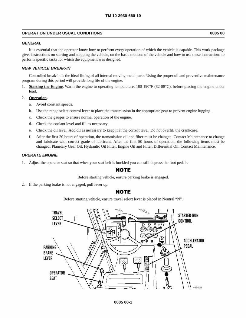
1. Adjust the operator seat so that when your seat belt is buckled you can still depress the foot pedals.
NOTEBefore starting vehicle, ensure parking brake is engaged.
2. If the parking brake is not engaged, pull lever up.
NOTEBefore starting vehicle, ensure travel select lever is placed in Neutral “N”.
409-024
STARTER-RUN
ACCELERATOR
TRAVEL
PARKING
OPERATOR
CONTROLSELECTLEVER
BRAKELEVER
SEAT
PEDAL
TM 10-3930-660-10
0005 00-2
OPERATION UNDER USUAL CONDITIONS - CONTINUED 0005 00
OPERATE ENGINE - CONTINUED
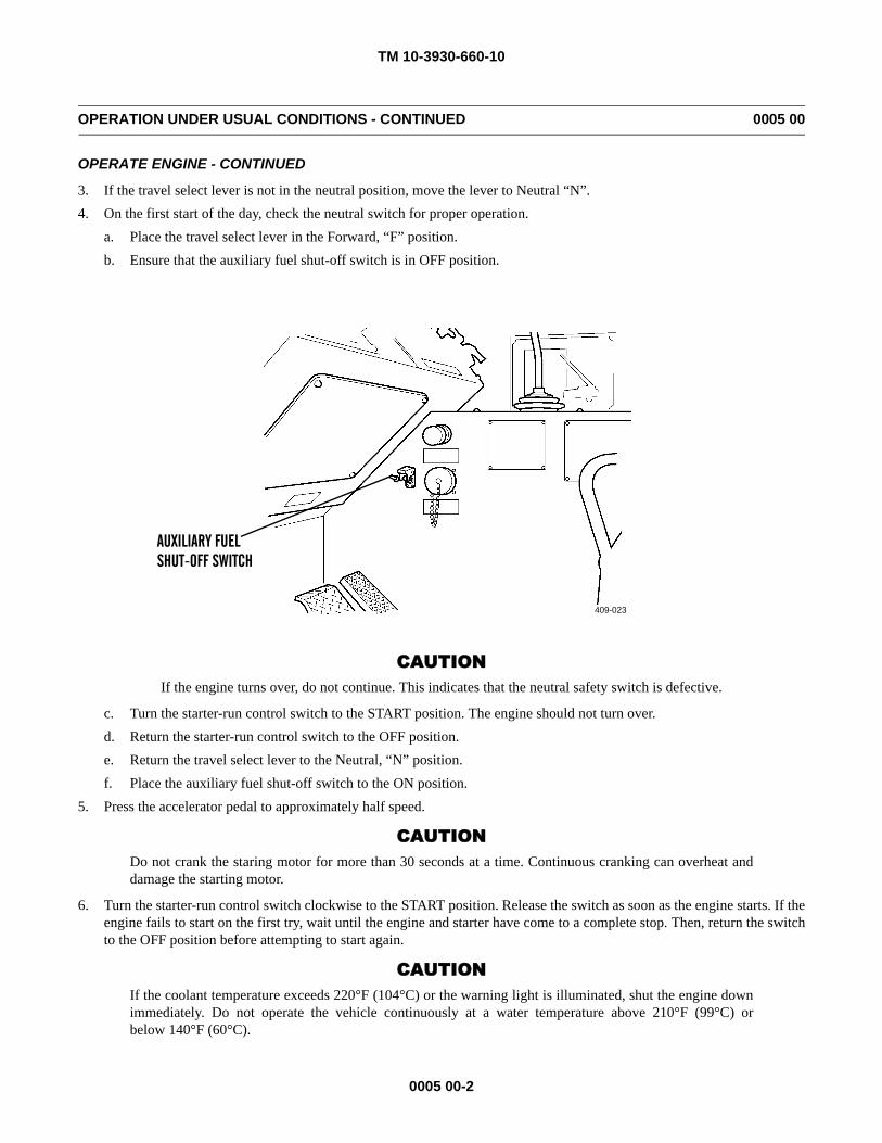
3. If the travel select lever is not in the neutral position, move the lever to Neutral “N”.4. On the first start of the day, check the neutral switch for proper operation.
a. Place the travel select lever in the Forward, “F” position.b. Ensure that the auxiliary fuel shut-off switch is in OFF position.
CAUTIONIf the engine turns over, do not continue. This indicates that the neutral safety switch is defective.
c. Turn the starter-run control switch to the START position. The engine should not turn over.d. Return the starter-run control switch to the OFF position.e. Return the travel select lever to the Neutral, “N” position.f. Place the auxiliary fuel shut-off switch to the ON position.
5. Press the accelerator pedal to approximately half speed.
CAUTIONDo not crank the staring motor for more than 30 seconds at a time. Continuous cranking can overheat anddamage the starting motor.
6. Turn the starter-run control switch clockwise to the START position. Release the switch as soon as the engine starts. If theengine fails to start on the first try, wait until the engine and starter have come to a complete stop. Then, return the switchto the OFF position before attempting to start again.
CAUTIONIf the coolant temperature exceeds 220°F (104°C) or the warning light is illuminated, shut the engine downimmediately. Do not operate the vehicle continuously at a water temperature above 210°F (99°C) orbelow 140°F (60°C).
409-023
AUXILIARY FUELSHUT-OFF SWITCH
TM 10-3930-660-10
0005 00-3
OPERATION UNDER USUAL CONDITIONS - CONTINUED 0005 00
OPERATE ENGINE - CONTINUED
CAUTION• If the oil pressure fluctuates or drops, or if the warning light is illuminated, stop the engine and find the cause.
Do not operate the engine at oil pressure lower than 10 psi (69 kPa).
• If oil pressure does not register within 15 seconds after the engine starts, stop the engine or serious damage mayoccur. Stop the engine by turning the starter-run control switch to the OFF position.
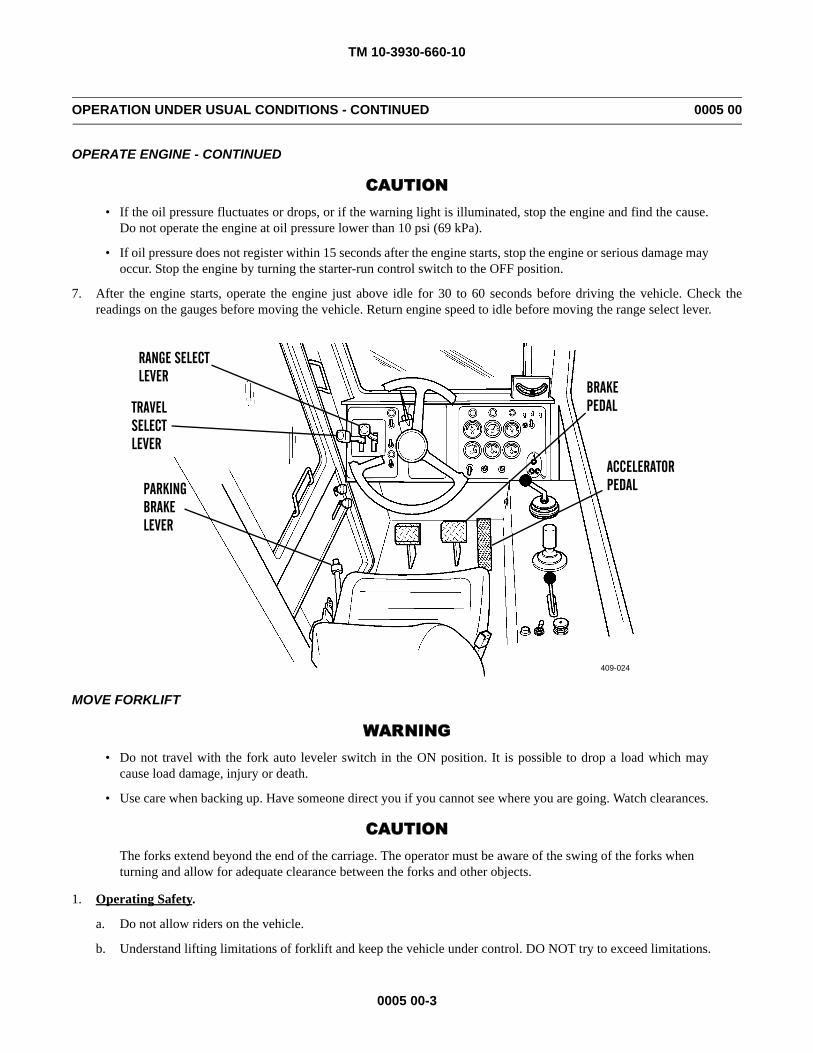
7. After the engine starts, operate the engine just above idle for 30 to 60 seconds before driving the vehicle. Check thereadings on the gauges before moving the vehicle. Return engine speed to idle before moving the range select lever.
MOVE FORKLIFT
WARNING• Do not travel with the fork auto leveler switch in the ON position. It is possible to drop a load which may
cause load damage, injury or death.
• Use care when backing up. Have someone direct you if you cannot see where you are going. Watch clearances.
CAUTIONThe forks extend beyond the end of the carriage. The operator must be aware of the swing of the forks whenturning and allow for adequate clearance between the forks and other objects.
1. Operating Safety.
a. Do not allow riders on the vehicle.
b. Understand lifting limitations of forklift and keep the vehicle under control. DO NOT try to exceed limitations.
409-024
BRAKE
ACCELERATOR
TRAVEL
PARKING
PEDALSELECTLEVER
BRAKELEVER
PEDAL
RANGE SELECTLEVER
TM 10-3930-660-10
0005 00-4
OPERATION UNDER USUAL CONDITIONS - CONTINUED 0005 00
MOVE FORKLIFT - CONTINUED
WARNINGThe 6K forklift is less stable when traveling with the load in a raised position. If you must move thevehicle with the load raised above the carry position (bottom of load 24 in. (610 mm) above the ground):
• Avoid sharp turns and sudden starts/stops.• Operate all controls smoothly.• Move very slowly.• Keep the vehicle level.
c. Always carry the load low (bottom of load 24 in. (610 mm) above the ground) for maximum stability.
CAUTIONMake sure the lower cab door is closed when operating the vehicle. Forklift wheels can contact thelower door if the door is left open.
d. Always operate the forklift with the lower cab door closed.
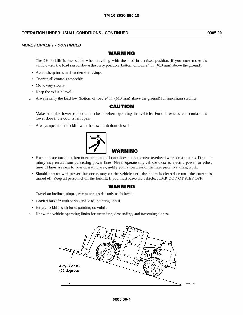
WARNING• Extreme care must be taken to ensure that the boom does not come near overhead wires or structures. Death or
injury may result from contacting power lines. Never operate this vehicle close to electric power, or other,lines. If lines are near to your operating area, notify your supervisor of the lines prior to starting work.
• Should contact with power line occur, stay on the vehicle until the boom is cleared or until the current isturned off. Keep all personnel off the forklift. If you must leave the vehicle, JUMP, DO NOT STEP OFF.
WARNINGTravel on inclines, slopes, ramps and grades only as follows:
• Loaded forklift: with forks (and load) pointing uphill.• Empty forklift: with forks pointing downhill.
e. Know the vehicle operating limits for ascending, descending, and traversing slopes.
409-025
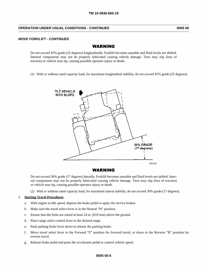
TM 10-3930-660-10
0005 00-5
OPERATION UNDER USUAL CONDITIONS - CONTINUED 0005 00
MOVE FORKLIFT - CONTINUED
WARNINGDo not exceed 45% grade (25 degrees) longitudinally. Forklift becomes unstable and fluid levels are shifted.Internal components may not be properly lubricated causing vehicle damage. Tires may slip (loss oftraction) or vehicle may tip, causing possible operator injury or death.
(1) With or without rated capacity load, for maximum longitudinal stability, do not exceed 45% grade (25 degrees).
WARNINGDo not exceed 30% grade (17 degrees) laterally. Forklift becomes unstable and fluid levels are shifted. Inter-nal components may not be properly lubricated causing vehicle damage. Tires may slip (loss of traction)or vehicle may tip, causing possible operator injury or death.
(2) With or without rated capacity load, for maximum lateral stability, do not exceed 30% grade (17 degrees).
2. Starting Travel Procedures.
a. With engine at idle speed, depress the brake pedal to apply the service brakes.
b. Make sure the travel select lever is in the Neutral “N” position.
c. Ensure that the forks are raised at least 24 in. (610 mm) above the ground.
d. Place range select control lever to the desired range.
e. Push parking brake lever down to release the parking brake.
f. Move travel select lever to the Forward “F” position for forward travel, or down to the Reverse “R” position forreverse travel.
g. Release brake pedal and press the accelerator pedal to control vehicle speed.
409-026
TM 10-3930-660-10
0005 00-6
OPERATION UNDER USUAL CONDITIONS - CONTINUED 0005 00
MOVE FORKLIFT - CONTINUED
3. Changing Direction of Travel.
WARNING
DO NOT STOP QUICKLY. The load may drop off the forks causing damage or personal injury.
a. Depress brake or transmission disconnect pedal to apply the service brakes and bring the forklift to a complete stop.
NOTE
When changing direction of travel, reduce engine speed.
b. Move travel select lever through Neutral, “N” to the desired direction.
4. Changing Gear Selection Range.
WARNING
DO NOT downshift at high speeds. Forklift will slow suddenly and drop the load or possibly cause operatorinjury.
CAUTION
• Operating the vehicle with a heavy load in high gear will cause the torque converter to slip excessively andthe transmission may overheat.
• Upshifting and downshifting should be done in the normal sequence of speeds.
NOTE
The gears should be engaged only after reaching the top speed of the next lower gear. If necessary, the fork-lift should be slowed by means of the service brakes.
a. Shifting to the next higher gear may be accomplished at any engine RPM while the forklift is in motion.
b. When downshifting, DO NOT over-rev the engine. Allow forklift to slow before shifting to the next lower gear.
5. Accelerating Hydraulic Functions.
a. Depress and hold transmission disconnect pedal.
b. Depress accelerator pedal to increase and maintain higher engine speed.
c. Perform desired hydraulic functions.
d. Reduce engine speed to idle after operations are completed.
e. Shift travel select control lever as necessary.
f. Slowly release transmission disconnect pedal.
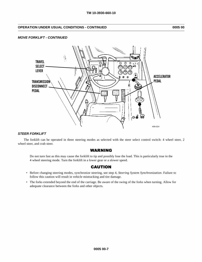
TM 10-3930-660-10
0005 00-7
OPERATION UNDER USUAL CONDITIONS - CONTINUED 0005 00
MOVE FORKLIFT - CONTINUED
STEER FORKLIFT
The forklift can be operated in three steering modes as selected with the steer select control switch: 4 wheel steer, 2wheel steer, and crab steer.
WARNINGDo not turn fast as this may cause the forklift to tip and possibly lose the load. This is particularly true in the4 wheel steering mode. Turn the forklift in a lower gear or a slower speed.
CAUTION• Before changing steering modes, synchronize steering, see step 4, Steering System Synchronization. Failure to
follow this caution will result in vehicle mistracking and tire damage.• The forks extended beyond the end of the carriage. Be aware of the swing of the forks when turning. Allow for
adequate clearance between the forks and other objects.
409-024
ACCELERATOR
TRAVEL
TRANSMISSION
SELECTLEVER
DISCONNECTPEDAL
PEDAL
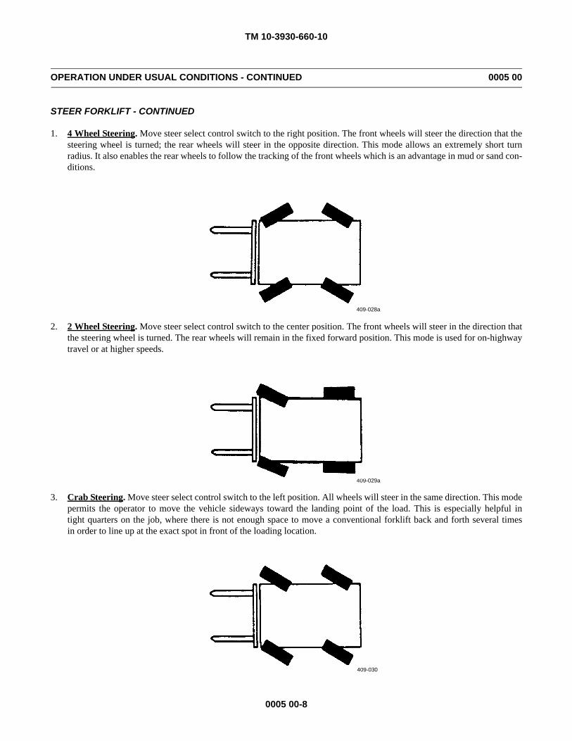
TM 10-3930-660-10
0005 00-8
OPERATION UNDER USUAL CONDITIONS - CONTINUED 0005 00
STEER FORKLIFT - CONTINUED
1. 4 Wheel Steering. Move steer select control switch to the right position. The front wheels will steer the direction that thesteering wheel is turned; the rear wheels will steer in the opposite direction. This mode allows an extremely short turnradius. It also enables the rear wheels to follow the tracking of the front wheels which is an advantage in mud or sand con-ditions.
2. 2 Wheel Steering. Move steer select control switch to the center position. The front wheels will steer in the direction thatthe steering wheel is turned. The rear wheels will remain in the fixed forward position. This mode is used for on-highwaytravel or at higher speeds.
3. Crab Steering. Move steer select control switch to the left position. All wheels will steer in the same direction. This modepermits the operator to move the vehicle sideways toward the landing point of the load. This is especially helpful intight quarters on the job, where there is not enough space to move a conventional forklift back and forth several timesin order to line up at the exact spot in front of the loading location.
409-028a
409-029a
409-030
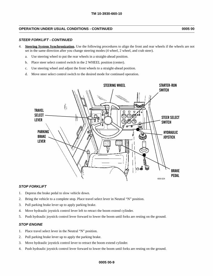
TM 10-3930-660-10
0005 00-9
OPERATION UNDER USUAL CONDITIONS - CONTINUED 0005 00
STEER FORKLIFT - CONTINUED
4. Steering System Synchronization. Use the following procedures to align the front and rear wheels if the wheels are notset in the same direction after you change steering modes (4 wheel, 2 wheel, and crab steer).
a. Use steering wheel to put the rear wheels in a straight-ahead position.
b. Place steer select control switch in the 2 WHEEL position (center).
c. Use steering wheel and adjust the front wheels to a straight-ahead position.
d. Move steer select control switch to the desired mode for continued operation.
STOP FORKLIFT
1. Depress the brake pedal to slow vehicle down.
2. Bring the vehicle to a complete stop. Place travel select lever in Neutral “N” position.
3. Pull parking brake lever up to apply parking brake.
4. Move hydraulic joystick control lever left to retract the boom extend cylinder.
5. Push hydraulic joystick control lever forward to lower the boom until forks are resting on the ground.
STOP ENGINE
1. Place travel select lever in the Neutral “N” position.
2. Pull parking brake lever up to apply the parking brake.
3. Move hydraulic joystick control lever to retract the boom extend cylinder.
4. Push hydraulic joystick control lever forward to lower the boom until forks are resting on the ground.
409-024
BRAKE
TRAVEL
PARKING
PEDAL
SELECTLEVER
BRAKELEVER
HYDRAULIC
STEERING WHEEL
JOYSTICK
STEER SELECTSWITCH
STARTER-RUNSWITCH
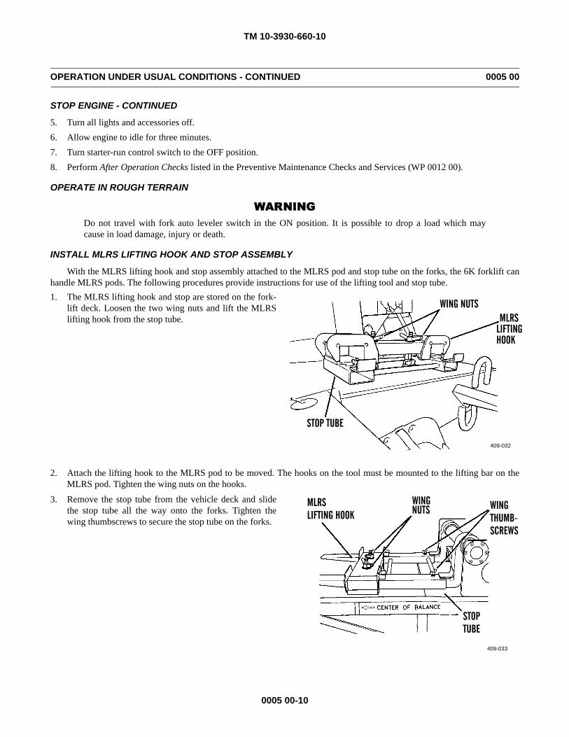
TM 10-3930-660-10
0005 00-10
OPERATION UNDER USUAL CONDITIONS - CONTINUED 0005 00
STOP ENGINE - CONTINUED
5. Turn all lights and accessories off.6. Allow engine to idle for three minutes.7. Turn starter-run control switch to the OFF position.8. Perform After Operation Checks listed in the Preventive Maintenance Checks and Services (WP 0012 00).
OPERATE IN ROUGH TERRAIN
WARNINGDo not travel with fork auto leveler switch in the ON position. It is possible to drop a load which maycause in load damage, injury or death.
INSTALL MLRS LIFTING HOOK AND STOP ASSEMBLY
With the MLRS lifting hook and stop assembly attached to the MLRS pod and stop tube on the forks, the 6K forklift canhandle MLRS pods. The following procedures provide instructions for use of the lifting tool and stop tube.1. The MLRS lifting hook and stop are stored on the fork-
lift deck. Loosen the two wing nuts and lift the MLRSlifting hook from the stop tube.
2. Attach the lifting hook to the MLRS pod to be moved. The hooks on the tool must be mounted to the lifting bar on theMLRS pod. Tighten the wing nuts on the hooks.
3. Remove the stop tube from the vehicle deck and slidethe stop tube all the way onto the forks. Tighten thewing thumbscrews to secure the stop tube on the forks.
409-032
WING NUTS
STOP TUBE
MLRSLIFTINGHOOK
409-033
MLRSLIFTING HOOK
WINGNUTS WING
TUBESTOP
THUMB-SCREWS
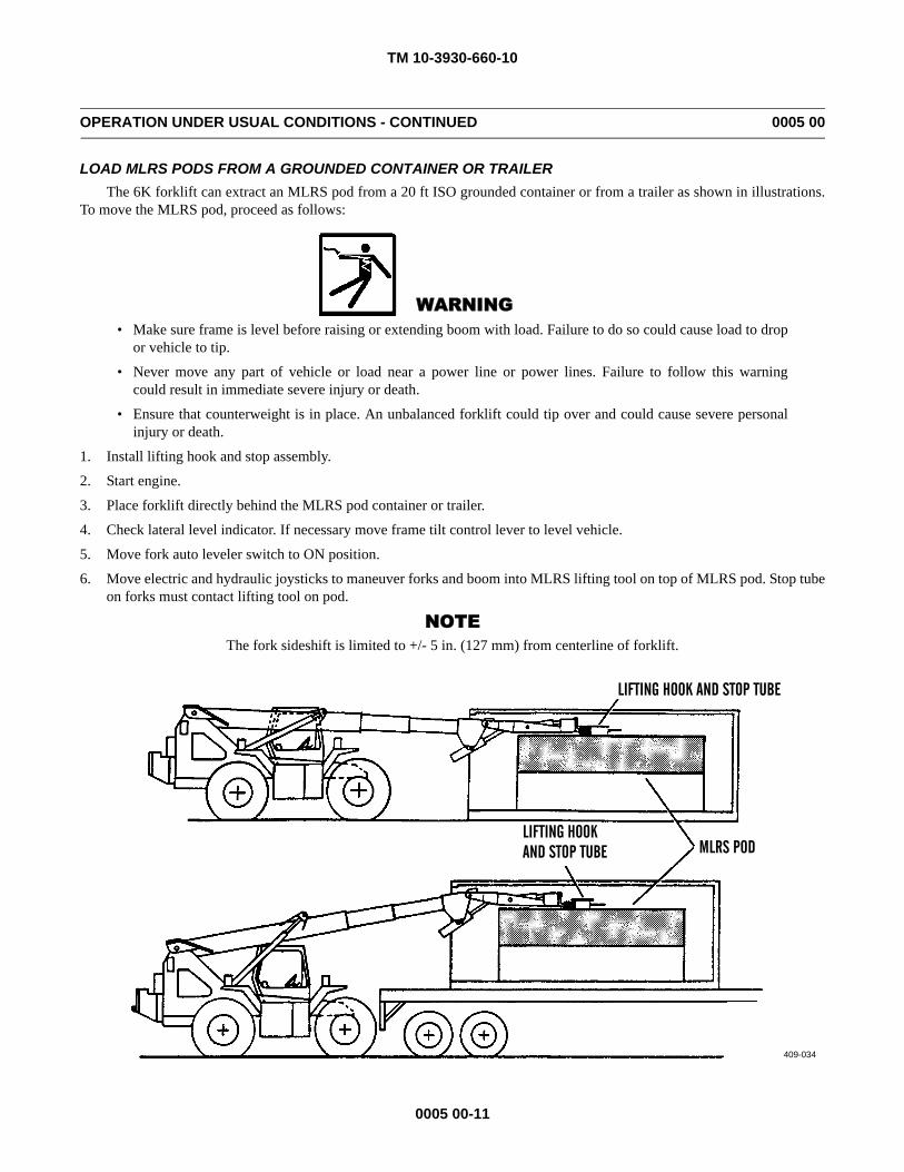
TM 10-3930-660-10
0005 00-11
OPERATION UNDER USUAL CONDITIONS - CONTINUED 0005 00
LOAD MLRS PODS FROM A GROUNDED CONTAINER OR TRAILERThe 6K forklift can extract an MLRS pod from a 20 ft ISO grounded container or from a trailer as shown in illustrations.
To move the MLRS pod, proceed as follows:
WARNING• Make sure frame is level before raising or extending boom with load. Failure to do so could cause load to drop
or vehicle to tip.
• Never move any part of vehicle or load near a power line or power lines. Failure to follow this warningcould result in immediate severe injury or death.
• Ensure that counterweight is in place. An unbalanced forklift could tip over and could cause severe personalinjury or death.
1. Install lifting hook and stop assembly.
2. Start engine.
3. Place forklift directly behind the MLRS pod container or trailer.
4. Check lateral level indicator. If necessary move frame tilt control lever to level vehicle.
5. Move fork auto leveler switch to ON position.
6. Move electric and hydraulic joysticks to maneuver forks and boom into MLRS lifting tool on top of MLRS pod. Stop tubeon forks must contact lifting tool on pod.
NOTEThe fork sideshift is limited to +/- 5 in. (127 mm) from centerline of forklift.
LIFTING HOOK AND STOP TUBE
MLRS PODLIFTING HOOKAND STOP TUBE
409-034
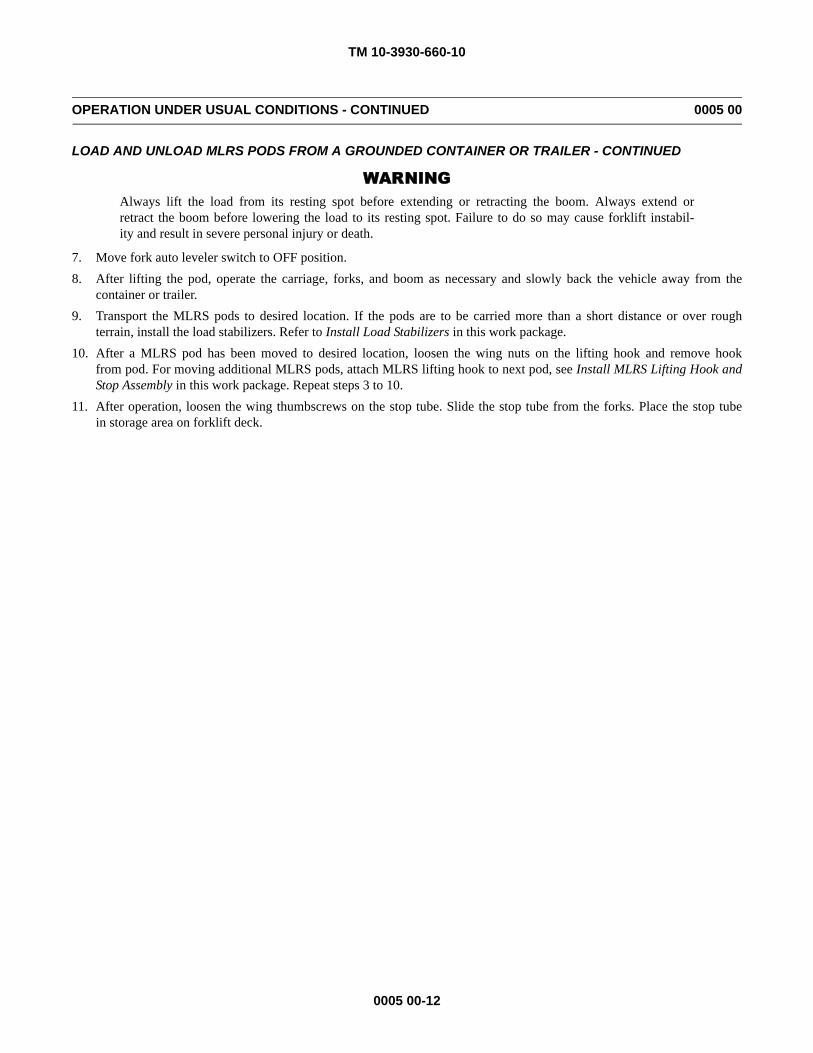
TM 10-3930-660-10
0005 00-12
OPERATION UNDER USUAL CONDITIONS - CONTINUED 0005 00
LOAD AND UNLOAD MLRS PODS FROM A GROUNDED CONTAINER OR TRAILER - CONTINUED
WARNINGAlways lift the load from its resting spot before extending or retracting the boom. Always extend orretract the boom before lowering the load to its resting spot. Failure to do so may cause forklift instabil-ity and result in severe personal injury or death.
7. Move fork auto leveler switch to OFF position.8. After lifting the pod, operate the carriage, forks, and boom as necessary and slowly back the vehicle away from the
container or trailer.9. Transport the MLRS pods to desired location. If the pods are to be carried more than a short distance or over rough
terrain, install the load stabilizers. Refer to Install Load Stabilizers in this work package.10. After a MLRS pod has been moved to desired location, loosen the wing nuts on the lifting hook and remove hook
from pod. For moving additional MLRS pods, attach MLRS lifting hook to next pod, see Install MLRS Lifting Hook andStop Assembly in this work package. Repeat steps 3 to 10.
11. After operation, loosen the wing thumbscrews on the stop tube. Slide the stop tube from the forks. Place the stop tubein storage area on forklift deck.
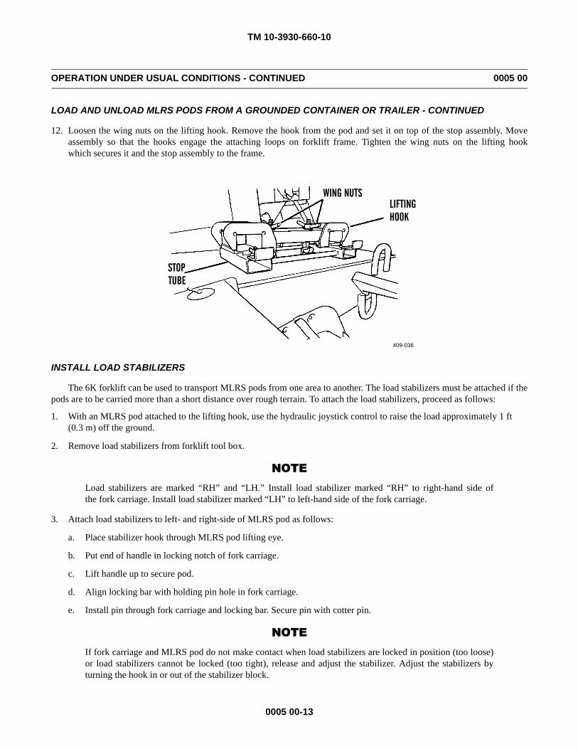
TM 10-3930-660-10
0005 00-13
OPERATION UNDER USUAL CONDITIONS - CONTINUED 0005 00
LOAD AND UNLOAD MLRS PODS FROM A GROUNDED CONTAINER OR TRAILER - CONTINUED
12. Loosen the wing nuts on the lifting hook. Remove the hook from the pod and set it on top of the stop assembly. Moveassembly so that the hooks engage the attaching loops on forklift frame. Tighten the wing nuts on the lifting hookwhich secures it and the stop assembly to the frame.
INSTALL LOAD STABILIZERS
The 6K forklift can be used to transport MLRS pods from one area to another. The load stabilizers must be attached if thepods are to be carried more than a short distance over rough terrain. To attach the load stabilizers, proceed as follows:
1. With an MLRS pod attached to the lifting hook, use the hydraulic joystick control to raise the load approximately 1 ft (0.3 m) off the ground.
2. Remove load stabilizers from forklift tool box.
NOTELoad stabilizers are marked “RH” and “LH.” Install load stabilizer marked “RH” to right-hand side ofthe fork carriage. Install load stabilizer marked “LH” to left-hand side of the fork carriage.
3. Attach load stabilizers to left- and right-side of MLRS pod as follows:
a. Place stabilizer hook through MLRS pod lifting eye.
b. Put end of handle in locking notch of fork carriage.
c. Lift handle up to secure pod.
d. Align locking bar with holding pin hole in fork carriage.
e. Install pin through fork carriage and locking bar. Secure pin with cotter pin.
NOTEIf fork carriage and MLRS pod do not make contact when load stabilizers are locked in position (too loose)or load stabilizers cannot be locked (too tight), release and adjust the stabilizer. Adjust the stabilizers byturning the hook in or out of the stabilizer block.
409-036
WING NUTSLIFTING
STOP TUBE
HOOK
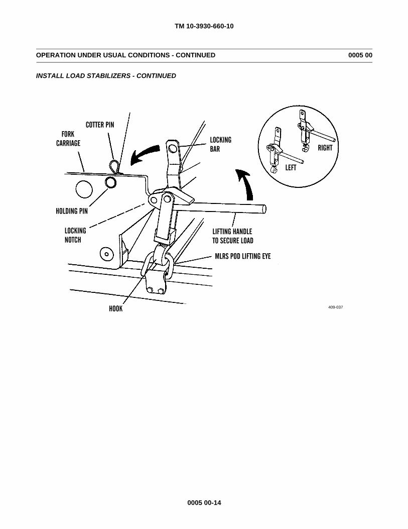
TM 10-3930-660-10
0005 00-14
OPERATION UNDER USUAL CONDITIONS - CONTINUED 0005 00
INSTALL LOAD STABILIZERS - CONTINUED
409-037
LIFTING HANDLETO SECURE LOAD
MLRS POD LIFTING EYE
HOOK
HOLDING PIN
COTTER PINFORK
CARRIAGEBAR
LEFT
RIGHT
NOTCHLOCKING
LOCKING
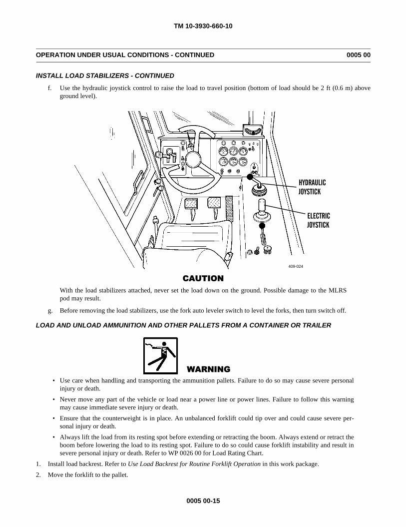
TM 10-3930-660-10
0005 00-15
OPERATION UNDER USUAL CONDITIONS - CONTINUED 0005 00
INSTALL LOAD STABILIZERS - CONTINUED
f. Use the hydraulic joystick control to raise the load to travel position (bottom of load should be 2 ft (0.6 m) aboveground level).
CAUTIONWith the load stabilizers attached, never set the load down on the ground. Possible damage to the MLRSpod may result.
g. Before removing the load stabilizers, use the fork auto leveler switch to level the forks, then turn switch off.
LOAD AND UNLOAD AMMUNITION AND OTHER PALLETS FROM A CONTAINER OR TRAILER
WARNING• Use care when handling and transporting the ammunition pallets. Failure to do so may cause severe personal
injury or death.
• Never move any part of the vehicle or load near a power line or power lines. Failure to follow this warningmay cause immediate severe injury or death.
• Ensure that the counterweight is in place. An unbalanced forklift could tip over and could cause severe per-sonal injury or death.
• Always lift the load from its resting spot before extending or retracting the boom. Always extend or retract theboom before lowering the load to its resting spot. Failure to do so could cause forklift instability and result insevere personal injury or death. Refer to WP 0026 00 for Load Rating Chart.
1. Install load backrest. Refer to Use Load Backrest for Routine Forklift Operation in this work package.2. Move the forklift to the pallet.
409-024
ELECTRICJOYSTICK
HYDRAULICJOYSTICK
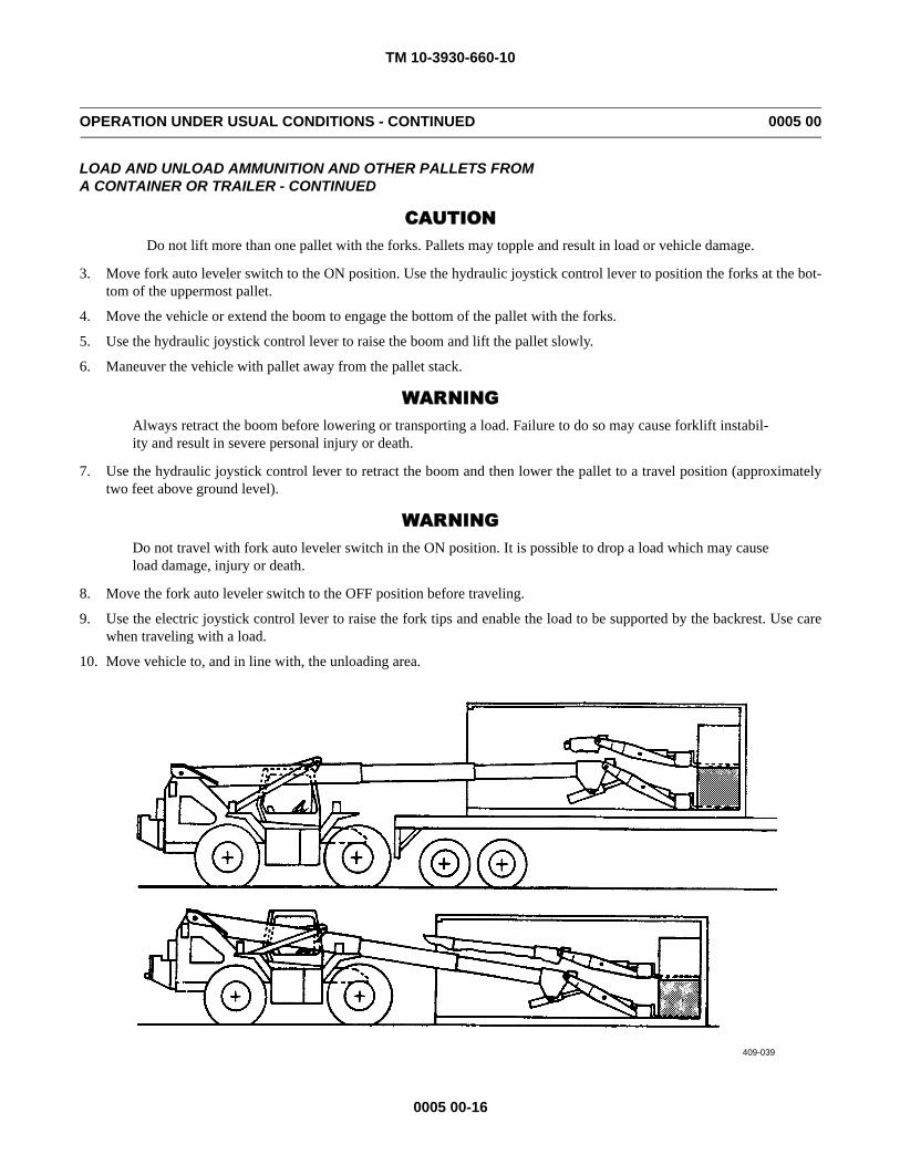
TM 10-3930-660-10
0005 00-16
OPERATION UNDER USUAL CONDITIONS - CONTINUED 0005 00
LOAD AND UNLOAD AMMUNITION AND OTHER PALLETS FROMA CONTAINER OR TRAILER - CONTINUED
CAUTIONDo not lift more than one pallet with the forks. Pallets may topple and result in load or vehicle damage.
3. Move fork auto leveler switch to the ON position. Use the hydraulic joystick control lever to position the forks at the bot-tom of the uppermost pallet.
4. Move the vehicle or extend the boom to engage the bottom of the pallet with the forks.
5. Use the hydraulic joystick control lever to raise the boom and lift the pallet slowly.
6. Maneuver the vehicle with pallet away from the pallet stack.
WARNINGAlways retract the boom before lowering or transporting a load. Failure to do so may cause forklift instabil-ity and result in severe personal injury or death.
7. Use the hydraulic joystick control lever to retract the boom and then lower the pallet to a travel position (approximatelytwo feet above ground level).
WARNINGDo not travel with fork auto leveler switch in the ON position. It is possible to drop a load which may causeload damage, injury or death.
8. Move the fork auto leveler switch to the OFF position before traveling.
9. Use the electric joystick control lever to raise the fork tips and enable the load to be supported by the backrest. Use carewhen traveling with a load.
10. Move vehicle to, and in line with, the unloading area.
409-039
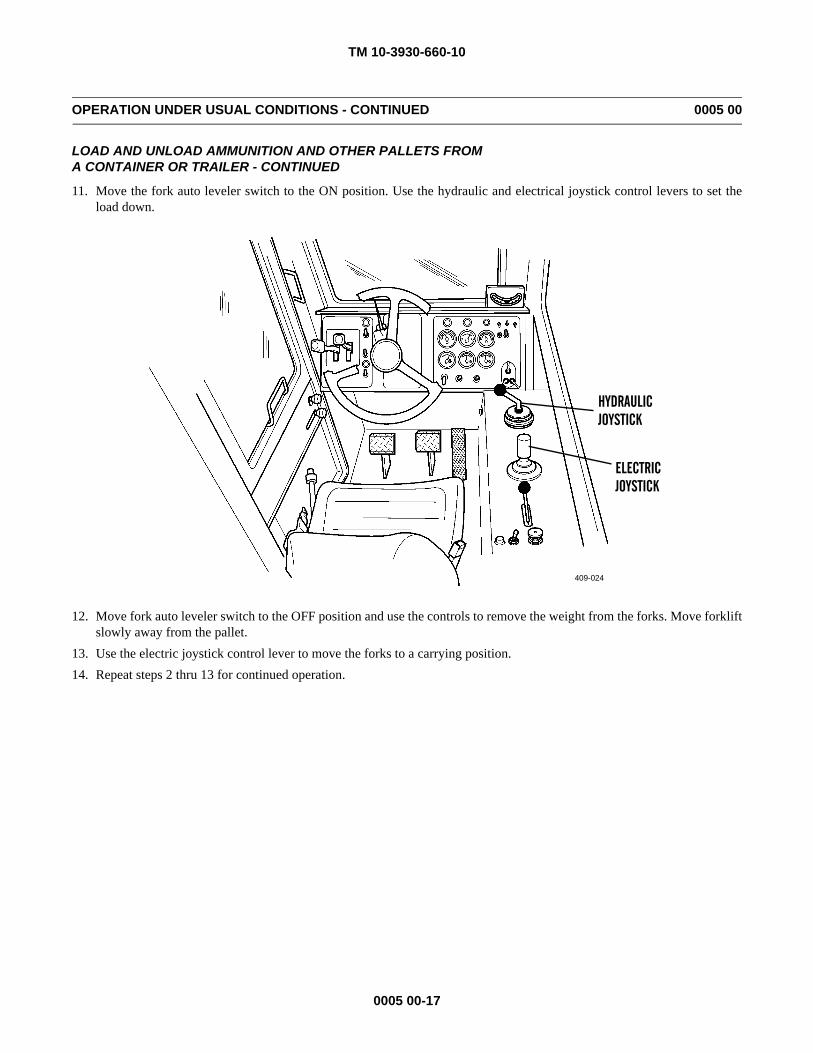
TM 10-3930-660-10
0005 00-17
OPERATION UNDER USUAL CONDITIONS - CONTINUED 0005 00
LOAD AND UNLOAD AMMUNITION AND OTHER PALLETS FROMA CONTAINER OR TRAILER - CONTINUED
11. Move the fork auto leveler switch to the ON position. Use the hydraulic and electrical joystick control levers to set theload down.
12. Move fork auto leveler switch to the OFF position and use the controls to remove the weight from the forks. Move forkliftslowly away from the pallet.
13. Use the electric joystick control lever to move the forks to a carrying position.14. Repeat steps 2 thru 13 for continued operation.
409-024
ELECTRICJOYSTICK
HYDRAULICJOYSTICK
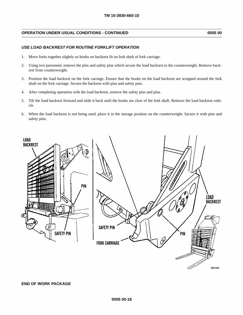
TM 10-3930-660-10
0005 00-18
OPERATION UNDER USUAL CONDITIONS - CONTINUED 0005 00
USE LOAD BACKREST FOR ROUTINE FORKLIFT OPERATION
1. Move forks together slightly so hooks on backrest fit on fork shaft of fork carriage.
2. Using two personnel, remove the pins and safety pins which secure the load backrest to the counterweight. Remove back-rest from counterweight.
3. Position the load backrest on the fork carriage. Ensure that the hooks on the load backrest are wrapped around the forkshaft on the fork carriage. Secure the backrest with pins and safety pins.
4. After completing operation with the load backrest, remove the safety pins and pins.
5. Tilt the load backrest forward and slide it back until the hooks are clear of the fork shaft. Remove the load backrest vehi-cle.
6. When the load backrest is not being used, place it in the storage position on the counterweight. Secure it with pins andsafety pins.
END OF WORK PACKAGE
409-041
LOADBACKREST
PINSAFETY PIN
FORK CARRIAGE
SAFETY PIN
PIN
BACKRESTLOAD
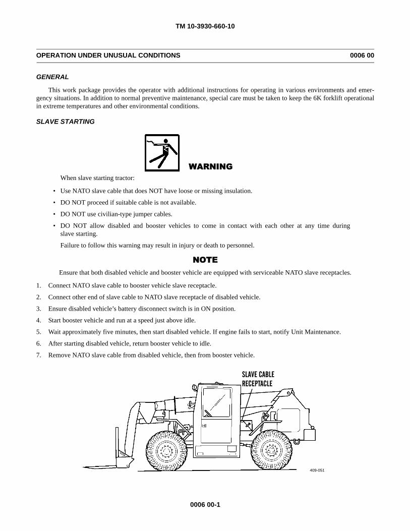
TM 10-3930-660-10
0006 00-1
OPERATION UNDER UNUSUAL CONDITIONS 0006 00
GENERAL
This work package provides the operator with additional instructions for operating in various environments and emer-gency situations. In addition to normal preventive maintenance, special care must be taken to keep the 6K forklift operationalin extreme temperatures and other environmental conditions.
SLAVE STARTING
WARNINGWhen slave starting tractor:
• Use NATO slave cable that does NOT have loose or missing insulation.
• DO NOT proceed if suitable cable is not available.
• DO NOT use civilian-type jumper cables.
• DO NOT allow disabled and booster vehicles to come in contact with each other at any time duringslave starting.
Failure to follow this warning may result in injury or death to personnel.
NOTEEnsure that both disabled vehicle and booster vehicle are equipped with serviceable NATO slave receptacles.
1. Connect NATO slave cable to booster vehicle slave receptacle.
2. Connect other end of slave cable to NATO slave receptacle of disabled vehicle.
3. Ensure disabled vehicle’s battery disconnect switch is in ON position.
4. Start booster vehicle and run at a speed just above idle.
5. Wait approximately five minutes, then start disabled vehicle. If engine fails to start, notify Unit Maintenance.
6. After starting disabled vehicle, return booster vehicle to idle.
7. Remove NATO slave cable from disabled vehicle, then from booster vehicle.
409-051
SLAVE CABLERECEPTACLE
TM 10-3930-660-10
0006 00-2
OPERATION UNDER UNUSUAL CONDITIONS - CONTINUED 0006 00
OPERATE IN EXTREME MOIST HEAT
CAUTION• Operating during periods of extreme heat [ambient temperatures above 100°F (38°C)] can cause engine
and hydraulic systems to overheat. Engine temperatures above 230°F (110°C) and hydraulic oiltemperatures above 250°F (121°C) can cause damage to engine and hydraulic system components.Check engine coolant temperature warning light and hydraulic oil temperature warning light oftenduring periods of extreme heat to prevent damage to engine and hydraulic system.
• Gaskets and seals are more likely to leak when engine and hydraulic system operating temperatures arehigh. Check engine and hydraulic oil levels more often during periods of extreme heat to prevent dam-age to engine and hydraulic system components. Check for leaks around gaskets, seals and fittings moreoften.
1. At Parking or Halt. a. If possible, park the 6K forklift under shelter.b. Dry the seat and wiring to prevent the formation of mildew.c. Keep the fuel tank full at all times to avoid condensation from forming in the tank.d. Contact Maintenance to check all points of lubrication.e. Clean and lubricate 6K forklift with correct grade of lubricants to help prevent deterioration. Have Maintenance
change air, fuel, transmission and hydraulic filter elements at shorter than normal intervals, as designated inMaintenance PMCS.
f. Perform operator PMCS more often than normal (WP 0011 and WP 0012 00).g. Do not over fill fuel tank. Extreme heat causes fuel to expand and overflow.h. Ensure that water is as free as possible of mineral deposits before adding coolant mixture to radiator. Local desert
water sources have high mineral deposits that will clog radiator.i. Ensure that water/antifreeze mixture is 50/50. This mixture raises coolant boiling point to help prevent overheating.j. High temperatures can damage hoses. Check radiator, fuel and lubricant hoses for leaks around fittings. Notify super-
visor if hoses are damaged.
TM 10-3930-660-10
0006 00-3
OPERATION UNDER UNUSUAL CONDITIONS - CONTINUED 0006 00
OPERATE IN EXTREME DRY HEAT (REFER TO FM 90-3, DESERT OPERATIONS)
CAUTION• Operating during periods of extreme heat [ambient temperatures above 100°F (38°C)] can cause engine
and hydraulic systems to overheat. Engine temperatures above 230°F (110°C) and hydraulic oiltemperatures above 250°F (121°C) can cause damage to engine and hydraulic system components.Check engine coolant temperature warning light and hydraulic oil temperature warning light oftenduring periods of extreme heat to prevent damage to engine and hydraulic system.
• Gaskets and seals are more likely to leak when engine and hydraulic system operating temperatures arehigh. Check engine and hydraulic oil levels more often during periods of extreme heat to prevent dam-age to engine and hydraulic system components. Check for leaks around gaskets, seals and fittings moreoften.
2. Preparation. Precautions must be taken to avoid overheating.
a. Contact Maintenance to drain, flush and refill cooling system.
b. Contact Maintenance to lubricate the 6K forklift with correct grade of lubricants.
3. Operation.
WARNING• DO NOT service cooling system unless engine has cooled. This is a pressurized cooling system and escaping
steam or hot coolant will cause serious burns.
• DO NOT remove cooling system radiator cap when engine is hot. Allow engine to cool down. Loosen cap tofirst stop and let any pressure out of cooling system, then remove cap. Failure to follow this warning may causeserious burns.
• Wear effective eye, glove, and skin protection when handling coolants. Failure to do so may cause injury.
a. Check the water temperature gauge at frequent intervals.
b. Check the air cleaner indicator frequently. Have the filter serviced often.
c. Clean and lubricate 6K forklift with correct grade of lubricants to help prevent deterioration. Have Maintenancechange air, fuel, transmission and hydraulic filter elements at shorter than normal intervals, as designated inMaintenance PMCS.
d. Perform operator PMCS more often than normal (WP 0011 and WP 0012 00).
e. Do not fill fuel tank completely. Extreme heat causes fuel to expand and overflow.
f. Ensure that water is as free as possible of mineral deposits before adding coolant mixture to radiator. Local desertwater sources have high mineral deposits that will clog radiator.
g. Ensure that water/antifreeze mixture is 50/50. This mixture raises coolant boiling point to help prevent overheating.
h. High temperatures can damage hoses. Check radiator, fuel and lubricant hoses for leaks around fittings. Notify super-visor if hoses are damaged.
i. Park 6K forklift under cover or in the shade, if possible.
TM 10-3930-660-10
0006 00-4
OPERATION UNDER UNUSUAL CONDITIONS - CONTINUED 0006 00
OPERATE IN EXTREME COLD
1. Introduction. Extreme cold causes many problems:a. Lubricants thicken or congeal.b. Batteries may freeze or lose their electrical efficiency.c. Fuel may not readily atomize for combustion.d. Various materials become hard, brittle, and easily damaged.e. Cooling system requires adequate protection from extreme cold.f. Fuels, lubricants, and antifreeze require special storage, handling, and use.
2. Preparation. Extensive preparation of mechanical equipment is required when extreme cold weather is anticipated. Thefollowing steps will help protect the vehicle against subfreezing temperatures.a. Contact Maintenance to prepare the cooling system by draining and then refilling with antifreeze appropriate for
anticipated temperatures. Refer to WP 0025 00 and TB 750-651, Use of Antifreeze Solutions, Antifreeze Extender,Cleaning Compounds.
b. Contact Maintenance to change the engine lubricating oil to the grade for cold weather operation.3. Starting the Engine.
a. Try starting the engine using the procedure in WP 0005 00.
WARNINGDo not operate the forklift with the emergency steer switch in the OFF position. If engine power is lost therewill be a loss of emergency steering capabilities. Failure to follow this precaution could result in severe per-sonal injury.
CAUTIONUse the engine primer button only while cranking the engine. Use only for starting a cold engine. Failure tofollow this precaution could cause engine damage.
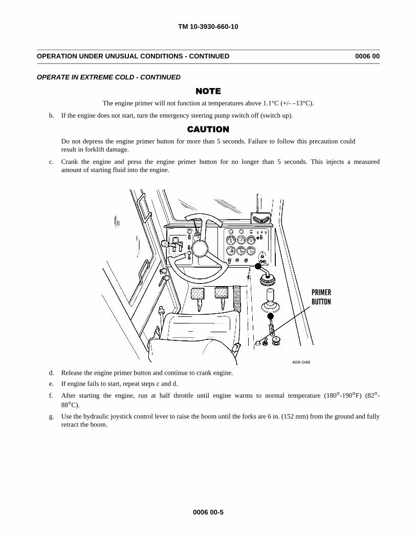
TM 10-3930-660-10
0006 00-5
OPERATION UNDER UNUSUAL CONDITIONS - CONTINUED 0006 00
OPERATE IN EXTREME COLD - CONTINUED
NOTEThe engine primer will not function at temperatures above 1.1°C (+/- –13°C).
b. If the engine does not start, turn the emergency steering pump switch off (switch up).
CAUTIONDo not depress the engine primer button for more than 5 seconds. Failure to follow this precaution couldresult in forklift damage.
c. Crank the engine and press the engine primer button for no longer than 5 seconds. This injects a measuredamount of starting fluid into the engine.
d. Release the engine primer button and continue to crank engine.e. If engine fails to start, repeat steps c and d.
f. After starting the engine, run at half throttle until engine warms to normal temperature (180°-190°F) (82°-88°C).
g. Use the hydraulic joystick control lever to raise the boom until the forks are 6 in. (152 mm) from the ground and fullyretract the boom.
409-048
PRIMERBUTTON
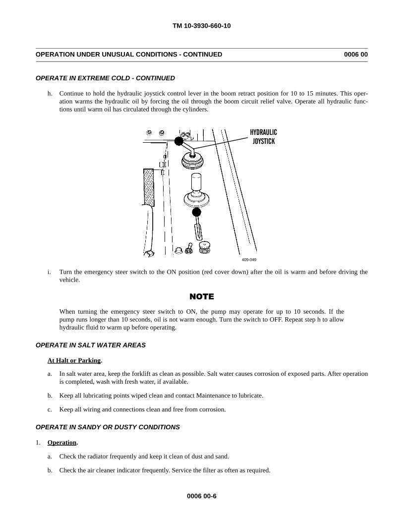
TM 10-3930-660-10
0006 00-6
OPERATION UNDER UNUSUAL CONDITIONS - CONTINUED 0006 00
OPERATE IN EXTREME COLD - CONTINUED
h. Continue to hold the hydraulic joystick control lever in the boom retract position for 10 to 15 minutes. This oper-ation warms the hydraulic oil by forcing the oil through the boom circuit relief valve. Operate all hydraulic func-tions until warm oil has circulated through the cylinders.
i. Turn the emergency steer switch to the ON position (red cover down) after the oil is warm and before driving thevehicle.
NOTE
When turning the emergency steer switch to ON, the pump may operate for up to 10 seconds. If thepump runs longer than 10 seconds, oil is not warm enough. Turn the switch to OFF. Repeat step h to allowhydraulic fluid to warm up before operating.
OPERATE IN SALT WATER AREAS
At Halt or Parking.
a. In salt water area, keep the forklift as clean as possible. Salt water causes corrosion of exposed parts. After operationis completed, wash with fresh water, if available.
b. Keep all lubricating points wiped clean and contact Maintenance to lubricate.
c. Keep all wiring and connections clean and free from corrosion.
OPERATE IN SANDY OR DUSTY CONDITIONS
1. Operation.
a. Check the radiator frequently and keep it clean of dust and sand.
b. Check the air cleaner indicator frequently. Service the filter as often as required.
409-049
HYDRAULICJOYSTICK
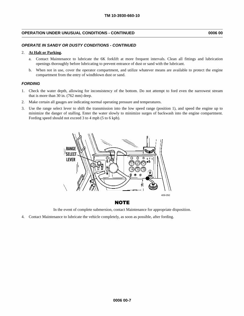
TM 10-3930-660-10
0006 00-7
OPERATION UNDER UNUSUAL CONDITIONS - CONTINUED 0006 00
OPERATE IN SANDY OR DUSTY CONDITIONS - CONTINUED
2. At Halt or Parking. a. Contact Maintenance to lubricate the 6K forklift at more frequent intervals. Clean all fittings and lubrication
openings thoroughly before lubricating to prevent entrance of dust or sand with the lubricant.b. When not in use, cover the operator compartment, and utilize whatever means are available to protect the engine
compartment from the entry of windblown dust or sand.
FORDING
1. Check the water depth, allowing for inconsistency of the bottom. Do not attempt to ford even the narrowest streamthat is more than 30 in. (762 mm) deep.
2. Make certain all gauges are indicating normal operating pressure and temperatures.3. Use the range select lever to shift the transmission into the low speed range (position 1), and speed the engine up to
minimize the danger of stalling. Enter the water slowly to minimize surges of backwash into the engine compartment.Fording speed should not exceed 3 to 4 mph (5 to 6 kph).
NOTEIn the event of complete submersion, contact Maintenance for appropriate disposition.
4. Contact Maintenance to lubricate the vehicle completely, as soon as possible, after fording.
409-050
RANGESELECTLEVER
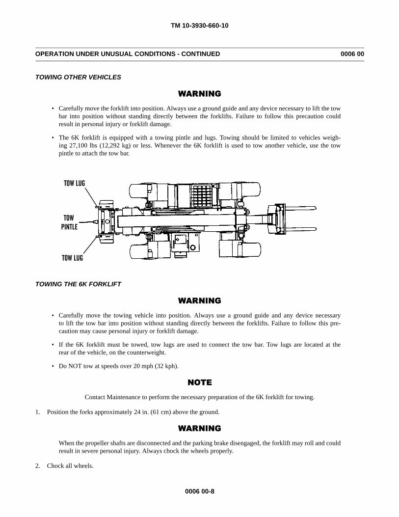
TM 10-3930-660-10
0006 00-8
OPERATION UNDER UNUSUAL CONDITIONS - CONTINUED 0006 00
TOWING OTHER VEHICLES
WARNING
• Carefully move the forklift into position. Always use a ground guide and any device necessary to lift the towbar into position without standing directly between the forklifts. Failure to follow this precaution couldresult in personal injury or forklift damage.
• The 6K forklift is equipped with a towing pintle and lugs. Towing should be limited to vehicles weigh-ing 27,100 lbs (12,292 kg) or less. Whenever the 6K forklift is used to tow another vehicle, use the towpintle to attach the tow bar.
TOWING THE 6K FORKLIFT
WARNING
• Carefully move the towing vehicle into position. Always use a ground guide and any device necessaryto lift the tow bar into position without standing directly between the forklifts. Failure to follow this pre-caution may cause personal injury or forklift damage.
• If the 6K forklift must be towed, tow lugs are used to connect the tow bar. Tow lugs are located at therear of the vehicle, on the counterweight.
• Do NOT tow at speeds over 20 mph (32 kph).
NOTE
Contact Maintenance to perform the necessary preparation of the 6K forklift for towing.
1. Position the forks approximately 24 in. (61 cm) above the ground.
WARNING
When the propeller shafts are disconnected and the parking brake disengaged, the forklift may roll and couldresult in severe personal injury. Always chock the wheels properly.
2. Chock all wheels.
TOWPINTLE
TOW LUG
TOW LUG
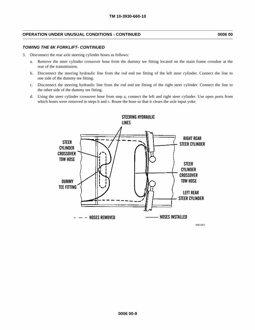
TM 10-3930-660-10
0006 00-9
OPERATION UNDER UNUSUAL CONDITIONS - CONTINUED 0006 00
TOWING THE 6K FORKLIFT- CONTINUED
3. Disconnect the rear axle steering cylinder hoses as follows:a. Remove the steer cylinder crossover hose from the dummy tee fitting located on the main frame crossbar at the
rear of the transmission.b. Disconnect the steering hydraulic line from the rod end tee fitting of the left steer cylinder. Connect the line to
one side of the dummy tee fitting.c. Disconnect the steering hydraulic line from the rod end tee fitting of the right steer cylinder. Connect the line to
the other side of the dummy tee fitting.d. Using the steer cylinder crossover hose from step a, connect the left and right steer cylinder. Use open ports from
which hoses were removed in steps b and c. Route the hose so that it clears the axle input yoke.
409-053
STEERING HYDRAULIC
STEERCYLINDER
CROSSOVERTOW HOSE
DUMMY TEE FITTING
RIGHT REARSTEER CYLINDER
STEERCYLINDER
CROSSOVERTOW HOSE
STEER CYLINDER
HOSES REMOVED HOSES INSTALLED
LEFT REAR
LINES
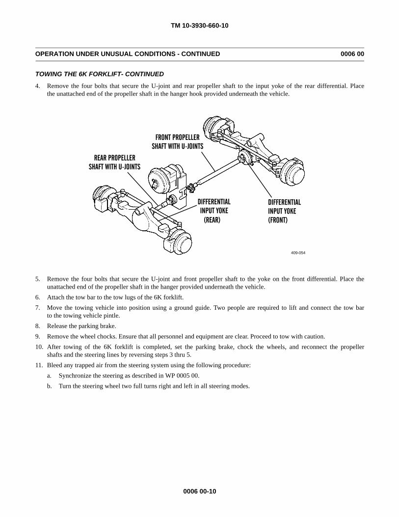
TM 10-3930-660-10
0006 00-10
OPERATION UNDER UNUSUAL CONDITIONS - CONTINUED 0006 00
TOWING THE 6K FORKLIFT- CONTINUED
4. Remove the four bolts that secure the U-joint and rear propeller shaft to the input yoke of the rear differential. Placethe unattached end of the propeller shaft in the hanger hook provided underneath the vehicle.
5. Remove the four bolts that secure the U-joint and front propeller shaft to the yoke on the front differential. Place theunattached end of the propeller shaft in the hanger provided underneath the vehicle.
6. Attach the tow bar to the tow lugs of the 6K forklift.7. Move the towing vehicle into position using a ground guide. Two people are required to lift and connect the tow bar
to the towing vehicle pintle.8. Release the parking brake.9. Remove the wheel chocks. Ensure that all personnel and equipment are clear. Proceed to tow with caution.10. After towing of the 6K forklift is completed, set the parking brake, chock the wheels, and reconnect the propeller
shafts and the steering lines by reversing steps 3 thru 5.11. Bleed any trapped air from the steering system using the following procedure:
a. Synchronize the steering as described in WP 0005 00.b. Turn the steering wheel two full turns right and left in all steering modes.
409-054
FRONT PROPELLERSHAFT WITH U-JOINTS
REAR PROPELLERSHAFT WITH U-JOINTS
DIFFERENTIALINPUT YOKE
(REAR)
DIFFERENTIALINPUT YOKE(FRONT)
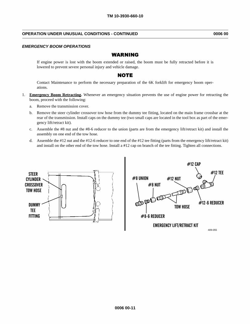
TM 10-3930-660-10
0006 00-11
OPERATION UNDER UNUSUAL CONDITIONS - CONTINUED 0006 00
EMERGENCY BOOM OPERATIONS
WARNINGIf engine power is lost with the boom extended or raised, the boom must be fully retracted before it islowered to prevent severe personal injury and vehicle damage.
NOTEContact Maintenance to perform the necessary preparation of the 6K forklift for emergency boom oper-ations.
1. Emergency Boom Retracting. Whenever an emergency situation prevents the use of engine power for retracting theboom, proceed with the following:a. Remove the transmission cover.b. Remove the steer cylinder crossover tow hose from the dummy tee fitting, located on the main frame crossbar at the
rear of the transmission. Install caps on the dummy tee (two small caps are located in the tool box as part of the emer-gency lift/retract kit).
c. Assemble the #8 nut and the #8-6 reducer to the union (parts are from the emergency lift/retract kit) and install theassembly on one end of the tow hose.
d. Assemble the #12 nut and the #12-6 reducer to one end of the #12 tee fitting (parts from the emergency lift/retract kit)and install on the other end of the tow hose. Install a #12 cap on branch of the tee fitting. Tighten all connections.
409-055
CYLINDERCROSSOVERTOW HOSE
DUMMY TEE
FITTING
#8 UNION#8 NUT
#12 NUT
#12 CAP
#12 TEE
TOW HOSE#12-6 REDUCER
#8-6 REDUCER
STEER
EMERGENCY LIFT/RETRACT KIT
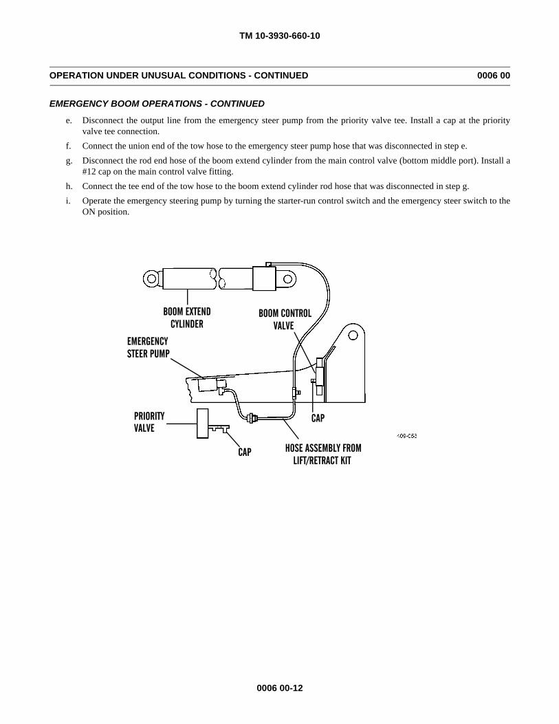
TM 10-3930-660-10
0006 00-12
OPERATION UNDER UNUSUAL CONDITIONS - CONTINUED 0006 00
EMERGENCY BOOM OPERATIONS - CONTINUED
e. Disconnect the output line from the emergency steer pump from the priority valve tee. Install a cap at the priorityvalve tee connection.
f. Connect the union end of the tow hose to the emergency steer pump hose that was disconnected in step e.g. Disconnect the rod end hose of the boom extend cylinder from the main control valve (bottom middle port). Install a
#12 cap on the main control valve fitting.h. Connect the tee end of the tow hose to the boom extend cylinder rod hose that was disconnected in step g.i. Operate the emergency steering pump by turning the starter-run control switch and the emergency steer switch to the
ON position.
BOOM EXTEND BOOM CONTROLVALVECYLINDER
EMERGENCYSTEER PUMP
PRIORITYVALVE
CAP
CAP HOSE ASSEMBLY FROMLIFT/RETRACT KIT
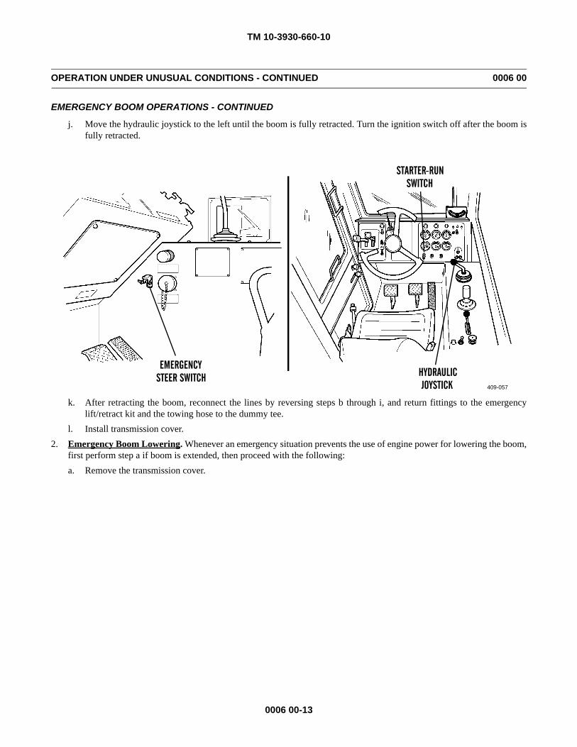
TM 10-3930-660-10
0006 00-13
OPERATION UNDER UNUSUAL CONDITIONS - CONTINUED 0006 00
EMERGENCY BOOM OPERATIONS - CONTINUED
j. Move the hydraulic joystick to the left until the boom is fully retracted. Turn the ignition switch off after the boom isfully retracted.
k. After retracting the boom, reconnect the lines by reversing steps b through i, and return fittings to the emergencylift/retract kit and the towing hose to the dummy tee.
l. Install transmission cover.2. Emergency Boom Lowering. Whenever an emergency situation prevents the use of engine power for lowering the boom,
first perform step a if boom is extended, then proceed with the following:a. Remove the transmission cover.
409-057
EMERGENCYSTEER SWITCH
STARTER-RUNSWITCH
HYDRAULICJOYSTICK
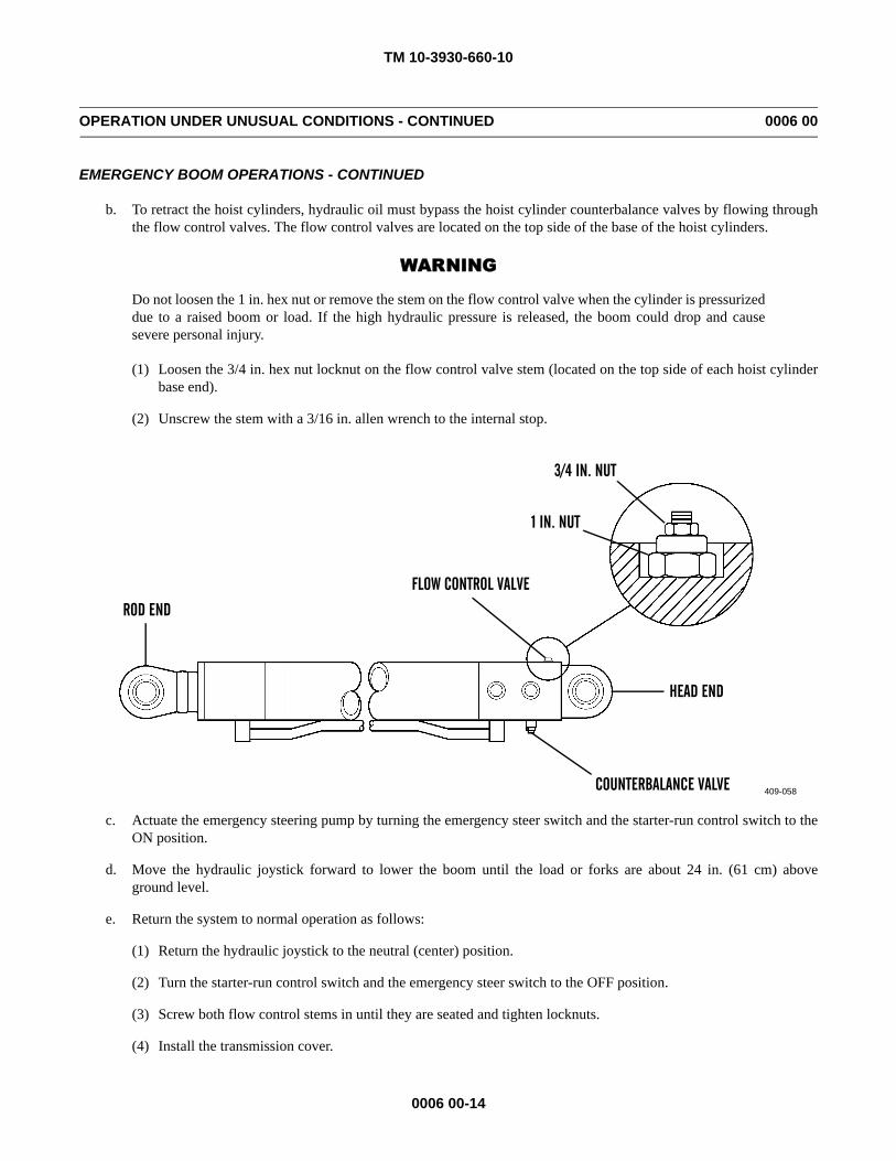
TM 10-3930-660-10
0006 00-14
OPERATION UNDER UNUSUAL CONDITIONS - CONTINUED 0006 00
EMERGENCY BOOM OPERATIONS - CONTINUED
b. To retract the hoist cylinders, hydraulic oil must bypass the hoist cylinder counterbalance valves by flowing throughthe flow control valves. The flow control valves are located on the top side of the base of the hoist cylinders.
WARNING
Do not loosen the 1 in. hex nut or remove the stem on the flow control valve when the cylinder is pressurizeddue to a raised boom or load. If the high hydraulic pressure is released, the boom could drop and causesevere personal injury.
(1) Loosen the 3/4 in. hex nut locknut on the flow control valve stem (located on the top side of each hoist cylinderbase end).
(2) Unscrew the stem with a 3/16 in. allen wrench to the internal stop.
c. Actuate the emergency steering pump by turning the emergency steer switch and the starter-run control switch to theON position.
d. Move the hydraulic joystick forward to lower the boom until the load or forks are about 24 in. (61 cm) aboveground level.
e. Return the system to normal operation as follows:
(1) Return the hydraulic joystick to the neutral (center) position.
(2) Turn the starter-run control switch and the emergency steer switch to the OFF position.
(3) Screw both flow control stems in until they are seated and tighten locknuts.
(4) Install the transmission cover.
409-058
ROD END
FLOW CONTROL VALVE
3/4 IN. NUT
1 IN. NUT
HEAD END
COUNTERBALANCE VALVE
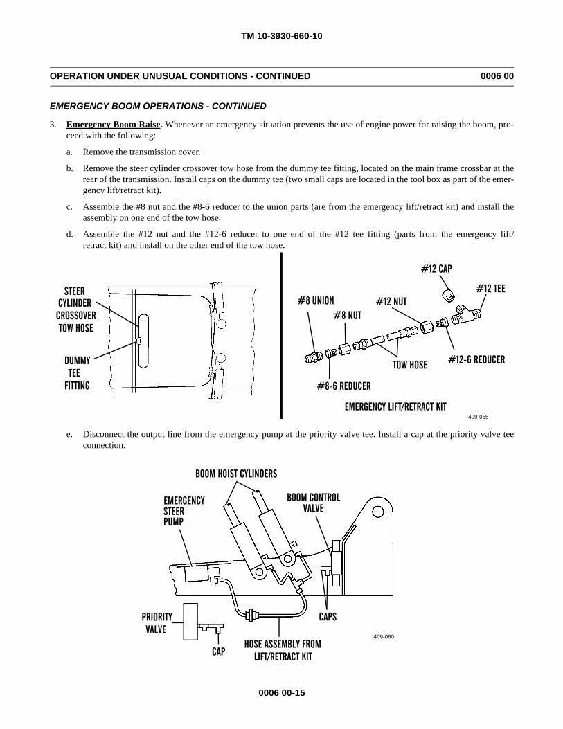
TM 10-3930-660-10
0006 00-15
OPERATION UNDER UNUSUAL CONDITIONS - CONTINUED 0006 00
EMERGENCY BOOM OPERATIONS - CONTINUED
3. Emergency Boom Raise. Whenever an emergency situation prevents the use of engine power for raising the boom, pro-ceed with the following:
a. Remove the transmission cover.
b. Remove the steer cylinder crossover tow hose from the dummy tee fitting, located on the main frame crossbar at therear of the transmission. Install caps on the dummy tee (two small caps are located in the tool box as part of the emer-gency lift/retract kit).
c. Assemble the #8 nut and the #8-6 reducer to the union parts (are from the emergency lift/retract kit) and install theassembly on one end of the tow hose.
d. Assemble the #12 nut and the #12-6 reducer to one end of the #12 tee fitting (parts from the emergency lift/retract kit) and install on the other end of the tow hose.
e. Disconnect the output line from the emergency pump at the priority valve tee. Install a cap at the priority valve teeconnection.
409-055
CYLINDERCROSSOVERTOW HOSE
DUMMY TEE
FITTING
#8 UNION#8 NUT
#12 NUT
#12 CAP
#12 TEE
TOW HOSE #12-6 REDUCER
#8-6 REDUCER
STEER
EMERGENCY LIFT/RETRACT KIT
409-060
BOOM HOIST CYLINDERS
BOOM CONTROLVALVE
CAPS
CAP
PRIORITYVALVE
EMERGENCYSTEER
HOSE ASSEMBLY FROMLIFT/RETRACT KIT
PUMP
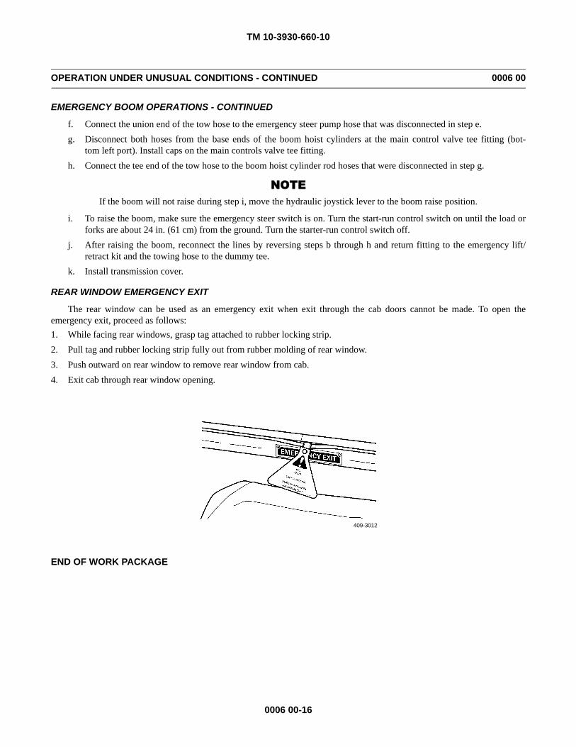
TM 10-3930-660-10
0006 00-16
OPERATION UNDER UNUSUAL CONDITIONS - CONTINUED 0006 00
EMERGENCY BOOM OPERATIONS - CONTINUED
f. Connect the union end of the tow hose to the emergency steer pump hose that was disconnected in step e.g. Disconnect both hoses from the base ends of the boom hoist cylinders at the main control valve tee fitting (bot-
tom left port). Install caps on the main controls valve tee fitting.h. Connect the tee end of the tow hose to the boom hoist cylinder rod hoses that were disconnected in step g.
NOTEIf the boom will not raise during step i, move the hydraulic joystick lever to the boom raise position.
i. To raise the boom, make sure the emergency steer switch is on. Turn the start-run control switch on until the load orforks are about 24 in. (61 cm) from the ground. Turn the starter-run control switch off.
j. After raising the boom, reconnect the lines by reversing steps b through h and return fitting to the emergency lift/retract kit and the towing hose to the dummy tee.
k. Install transmission cover.
REAR WINDOW EMERGENCY EXIT
The rear window can be used as an emergency exit when exit through the cab doors cannot be made. To open theemergency exit, proceed as follows:1. While facing rear windows, grasp tag attached to rubber locking strip.2. Pull tag and rubber locking strip fully out from rubber molding of rear window.3. Push outward on rear window to remove rear window from cab.4. Exit cab through rear window opening.
END OF WORK PACKAGE
409-3012
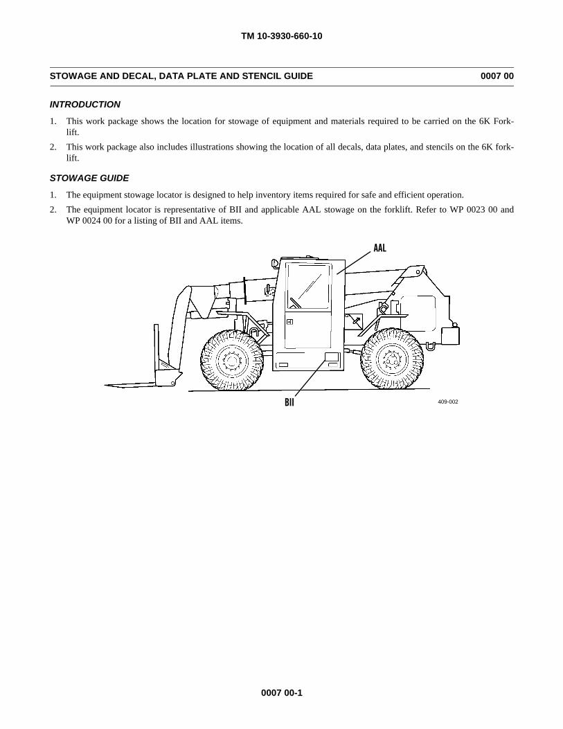
TM 10-3930-660-10
0007 00-1
STOWAGE AND DECAL, DATA PLATE AND STENCIL GUIDE 0007 00
INTRODUCTION
1. This work package shows the location for stowage of equipment and materials required to be carried on the 6K Fork-lift.
2. This work package also includes illustrations showing the location of all decals, data plates, and stencils on the 6K fork-lift.
STOWAGE GUIDE
1. The equipment stowage locator is designed to help inventory items required for safe and efficient operation.2. The equipment locator is representative of BII and applicable AAL stowage on the forklift. Refer to WP 0023 00 and
WP 0024 00 for a listing of BII and AAL items.
409-002BII
AAL
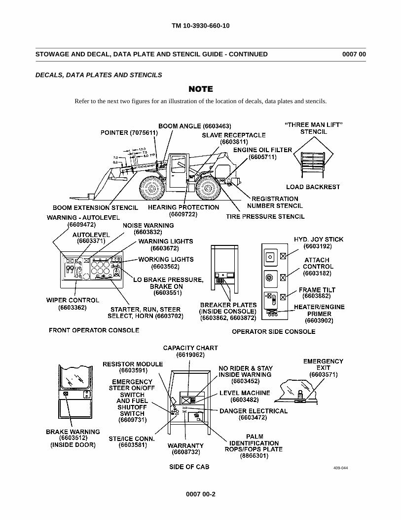
TM 10-3930-660-10
0007 00-2
STOWAGE AND DECAL, DATA PLATE AND STENCIL GUIDE - CONTINUED 0007 00
DECALS, DATA PLATES AND STENCILS
NOTERefer to the next two figures for an illustration of the location of decals, data plates and stencils.
409-044
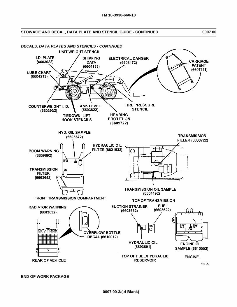
TM 10-3930-660-10
0007 00-3/(-4 Blank)
STOWAGE AND DECAL, DATA PLATE AND STENCIL GUIDE - CONTINUED 0007 00
DECALS, DATA PLATES AND STENCILS - CONTINUED
END OF WORK PACKAGE

TM 10-3930-660-10
CHAPTER 3OPERATOR TROUBLESHOOTING

TM 10-3930-660-10
0008 00-1/(-2 Blank)
TROUBLESHOOTING INTRODUCTION 0008 00
INTRODUCTION
1. This chapter provides information for identifying and correcting malfunctions which may develop while operating the 6KVariable Reach Rough Terrain Forklift Truck.
2. The Troubleshooting Symptom Index in WP 0009 00 lists common malfunctions which may occur and refers you to theproper page in WP 0010 00 for a troubleshooting procedure.
3. If you are unsure of the location of an item mentioned in troubleshooting, refer to WP 0002 00 or WP 0004 00.4. Before performing troubleshooting, read and follow all safety instructions found in the Warning Summary at the front of
this manual.5. The Troubleshooting Symptom Index cannot list all malfunctions that may occur, nor all tests or inspections and correc-
tive actions. If a malfunction is not listed, or is not corrected by the listed corrective actions, notify supervisor.6. When troubleshooting a malfunction:
a. Locate the symptom or symptoms in WP 0009 00 that best describe the malfunction.b. Turn to the page in WP 0010 00 where the troubleshooting procedures for the malfunction in question are described.
Headings at the top of each page show how each troubleshooting procedure is organized: MALFUNCTION, TESTOR INSPECTION (in step number order), and CORRECTIVE ACTION.
c. Perform each step in the order listed until the malfunction is corrected. DO NOT perform any maintenance taskunless the troubleshooting procedure tells you to do so.
EXPLANATION OF COLUMNS
The columns in Table 1 in WP 0010 00 are defined as follows:1. MALFUNCTION. A visual or operational indication that something is wrong with the equipment.2. TEST OR INSPECTION. A procedure to isolate the problem in a system or component.3. CORRECTIVE ACTION. A procedure to correct the problem.
END OF WORK PACKAGE

TM 10-3930-660-10
0009 00-1/(-2 Blank)
TROUBLESHOOTING SYMPTOM INDEX 0009 00
Malfunction/Symptom Troubleshooting Procedure Page
All Hydraulic Functions Operate Slowly. . . . . . . . . . . . . . . . . . . . . . . . . . . . . . . . . . . . . . . . . . . . . . . . . . . . . . . . 0010 00-3Engine Cranks But Will Not Start . . . . . . . . . . . . . . . . . . . . . . . . . . . . . . . . . . . . . . . . . . . . . . . . . . . . . . . . . . . . . 0010 00-1Engine Misfires or Runs Rough. . . . . . . . . . . . . . . . . . . . . . . . . . . . . . . . . . . . . . . . . . . . . . . . . . . . . . . . . . . . . . . 0010 00-1Engine Overheats . . . . . . . . . . . . . . . . . . . . . . . . . . . . . . . . . . . . . . . . . . . . . . . . . . . . . . . . . . . . . . . . . . . . . . . . . . 0010 00-2Engine Primer Button Does Not Work. . . . . . . . . . . . . . . . . . . . . . . . . . . . . . . . . . . . . . . . . . . . . . . . . . . . . . . . . . 0010 00-3Engine Will Not Crank. . . . . . . . . . . . . . . . . . . . . . . . . . . . . . . . . . . . . . . . . . . . . . . . . . . . . . . . . . . . . . . . . . . . . . 0010 00-1Forklift Starts But Will Not Move . . . . . . . . . . . . . . . . . . . . . . . . . . . . . . . . . . . . . . . . . . . . . . . . . . . . . . . . . . . . . 0010 00-2Forks Will Not Automatically Level . . . . . . . . . . . . . . . . . . . . . . . . . . . . . . . . . . . . . . . . . . . . . . . . . . . . . . . . . . . 0010 00-3Front and Rear Wheels Are Not Aligned in the Straight Ahead Position . . . . . . . . . . . . . . . . . . . . . . . . . . . . . . . 0010 00-3Hydraulic Oil is Foaming. . . . . . . . . . . . . . . . . . . . . . . . . . . . . . . . . . . . . . . . . . . . . . . . . . . . . . . . . . . . . . . . . . . . 0010 00-3Low Engine Oil Pressure . . . . . . . . . . . . . . . . . . . . . . . . . . . . . . . . . . . . . . . . . . . . . . . . . . . . . . . . . . . . . . . . . . . . 0010 00-2Low Engine Power. . . . . . . . . . . . . . . . . . . . . . . . . . . . . . . . . . . . . . . . . . . . . . . . . . . . . . . . . . . . . . . . . . . . . . . . . 0010 00-1Only One Heater Fan Operates . . . . . . . . . . . . . . . . . . . . . . . . . . . . . . . . . . . . . . . . . . . . . . . . . . . . . . . . . . . . . . . 0010 00-3Parking Brake Will Not Hold Forklift . . . . . . . . . . . . . . . . . . . . . . . . . . . . . . . . . . . . . . . . . . . . . . . . . . . . . . . . . . 0010 00-4Parking Brake Will Not Release . . . . . . . . . . . . . . . . . . . . . . . . . . . . . . . . . . . . . . . . . . . . . . . . . . . . . . . . . . . . . . 0010 00-4Poor or No Brakes . . . . . . . . . . . . . . . . . . . . . . . . . . . . . . . . . . . . . . . . . . . . . . . . . . . . . . . . . . . . . . . . . . . . . . . . . 0010 00-3
END OF WORK PACKAGE

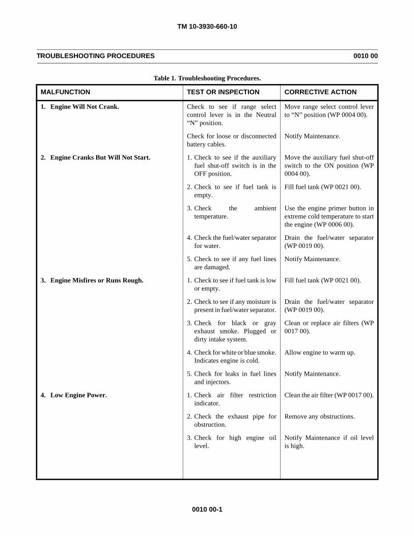
TM 10-3930-660-10
0010 00-1
TROUBLESHOOTING PROCEDURES 0010 00
Table 1. Troubleshooting Procedures.
MALFUNCTION TEST OR INSPECTION CORRECTIVE ACTION
1. Engine Will Not Crank. Check to see if range selectcontrol lever is in the Neutral“N” position.
Move range select control leverto “N” position (WP 0004 00).
Check for loose or disconnectedbattery cables.
Notify Maintenance.
2. Engine Cranks But Will Not Start. 1. Check to see if the auxiliaryfuel shut-off switch is in theOFF position.
Move the auxiliary fuel shut-offswitch to the ON position (WP0004 00).
2. Check to see if fuel tank isempty.
Fill fuel tank (WP 0021 00).
3. Check the ambienttemperature.
Use the engine primer button inextreme cold temperature to startthe engine (WP 0006 00).
4. Check the fuel/water separatorfor water.
Drain the fuel/water separator(WP 0019 00).
5. Check to see if any fuel linesare damaged.
Notify Maintenance.
3. Engine Misfires or Runs Rough. 1. Check to see if fuel tank is lowor empty.
Fill fuel tank (WP 0021 00).
2. Check to see if any moisture ispresent in fuel/water separator.
Drain the fuel/water separator(WP 0019 00).
3. Check for black or grayexhaust smoke. Plugged ordirty intake system.
Clean or replace air filters (WP0017 00).
4. Check for white or blue smoke.Indicates engine is cold.
Allow engine to warm up.
5. Check for leaks in fuel linesand injectors.
Notify Maintenance.
4. Low Engine Power. 1. Check air filter restrictionindicator.
Clean the air filter (WP 0017 00).
2. Check the exhaust pipe forobstruction.
Remove any obstructions.
3. Check for high engine oillevel.
Notify Maintenance if oil levelis high.
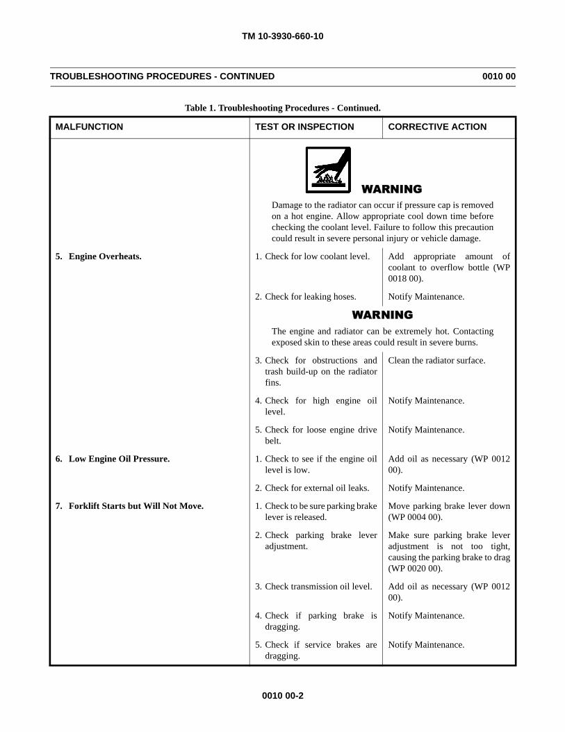
TM 10-3930-660-10
0010 00-2
TROUBLESHOOTING PROCEDURES - CONTINUED 0010 00
Table 1. Troubleshooting Procedures - Continued.
MALFUNCTION TEST OR INSPECTION CORRECTIVE ACTION
WARNINGDamage to the radiator can occur if pressure cap is removedon a hot engine. Allow appropriate cool down time beforechecking the coolant level. Failure to follow this precautioncould result in severe personal injury or vehicle damage.
5. Engine Overheats. 1. Check for low coolant level. Add appropriate amount ofcoolant to overflow bottle (WP0018 00).
2. Check for leaking hoses. Notify Maintenance.
WARNINGThe engine and radiator can be extremely hot. Contactingexposed skin to these areas could result in severe burns.
3. Check for obstructions andtrash build-up on the radiatorfins.
Clean the radiator surface.
4. Check for high engine oillevel.
Notify Maintenance.
5. Check for loose engine drivebelt.
Notify Maintenance.
6. Low Engine Oil Pressure. 1. Check to see if the engine oillevel is low.
Add oil as necessary (WP 001200).
2. Check for external oil leaks. Notify Maintenance.
7. Forklift Starts but Will Not Move. 1. Check to be sure parking brakelever is released.
Move parking brake lever down(WP 0004 00).
2. Check parking brake leveradjustment.
Make sure parking brake leveradjustment is not too tight,causing the parking brake to drag(WP 0020 00).
3. Check transmission oil level. Add oil as necessary (WP 001200).
4. Check if parking brake isdragging.
Notify Maintenance.
5. Check if service brakes aredragging.
Notify Maintenance.
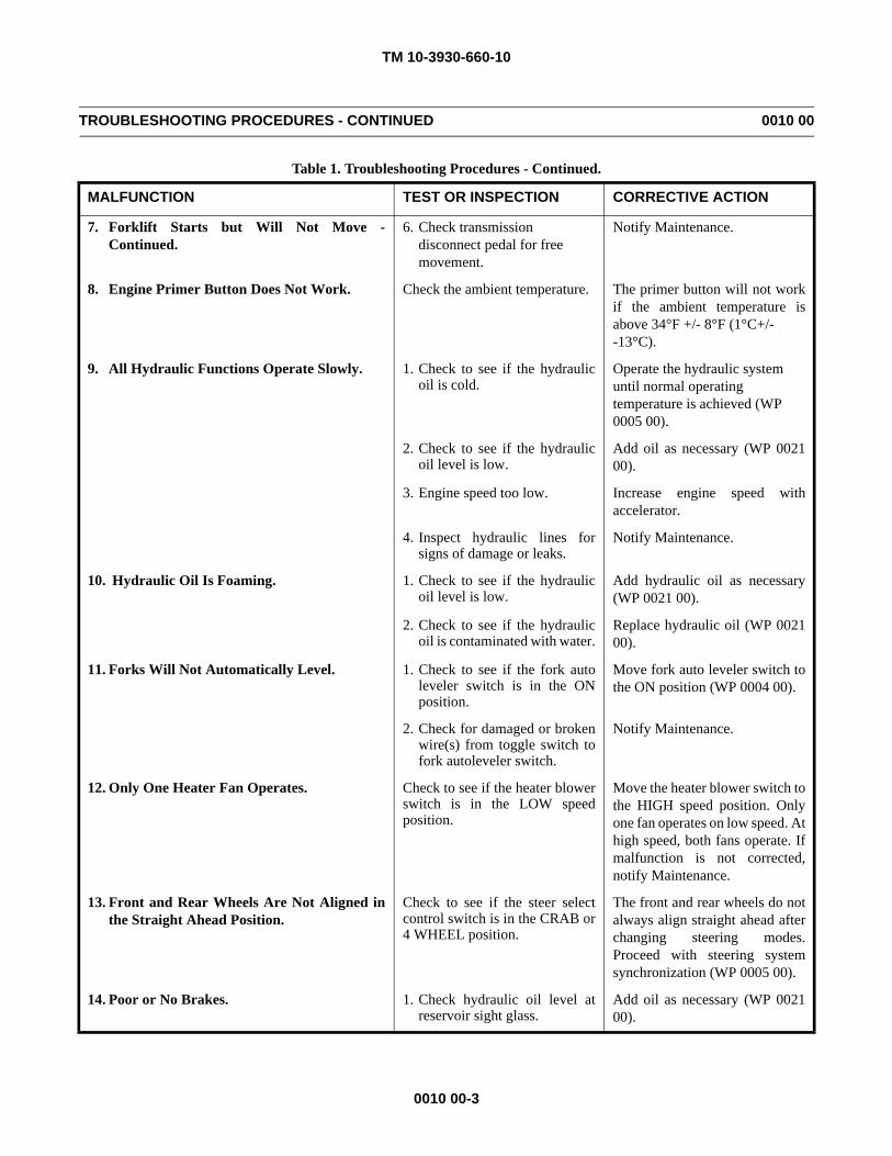
TM 10-3930-660-10
0010 00-3
TROUBLESHOOTING PROCEDURES - CONTINUED 0010 00
Table 1. Troubleshooting Procedures - Continued.
MALFUNCTION TEST OR INSPECTION CORRECTIVE ACTION
7. Forklift Starts but Will Not Move -Continued.
6. Check transmission disconnect pedal for free movement.
Notify Maintenance.
8. Engine Primer Button Does Not Work. Check the ambient temperature. The primer button will not workif the ambient temperature isabove 34°F +/- 8°F (1°C+/- -13°C).
9. All Hydraulic Functions Operate Slowly. 1. Check to see if the hydraulicoil is cold.
Operate the hydraulic system until normal operating temperature is achieved (WP 0005 00).
2. Check to see if the hydraulicoil level is low.
Add oil as necessary (WP 002100).
3. Engine speed too low. Increase engine speed withaccelerator.
4. Inspect hydraulic lines forsigns of damage or leaks.
Notify Maintenance.
10. Hydraulic Oil Is Foaming. 1. Check to see if the hydraulicoil level is low.
Add hydraulic oil as necessary(WP 0021 00).
2. Check to see if the hydraulicoil is contaminated with water.
Replace hydraulic oil (WP 002100).
11. Forks Will Not Automatically Level. 1. Check to see if the fork autoleveler switch is in the ONposition.
Move fork auto leveler switch tothe ON position (WP 0004 00).
2. Check for damaged or brokenwire(s) from toggle switch tofork autoleveler switch.
Notify Maintenance.
12. Only One Heater Fan Operates. Check to see if the heater blowerswitch is in the LOW speedposition.
Move the heater blower switch tothe HIGH speed position. Onlyone fan operates on low speed. Athigh speed, both fans operate. Ifmalfunction is not corrected,notify Maintenance.
13. Front and Rear Wheels Are Not Aligned inthe Straight Ahead Position.
Check to see if the steer selectcontrol switch is in the CRAB or4 WHEEL position.
The front and rear wheels do notalways align straight ahead afterchanging steering modes.Proceed with steering systemsynchronization (WP 0005 00).
14. Poor or No Brakes. 1. Check hydraulic oil level atreservoir sight glass.
Add oil as necessary (WP 002100).
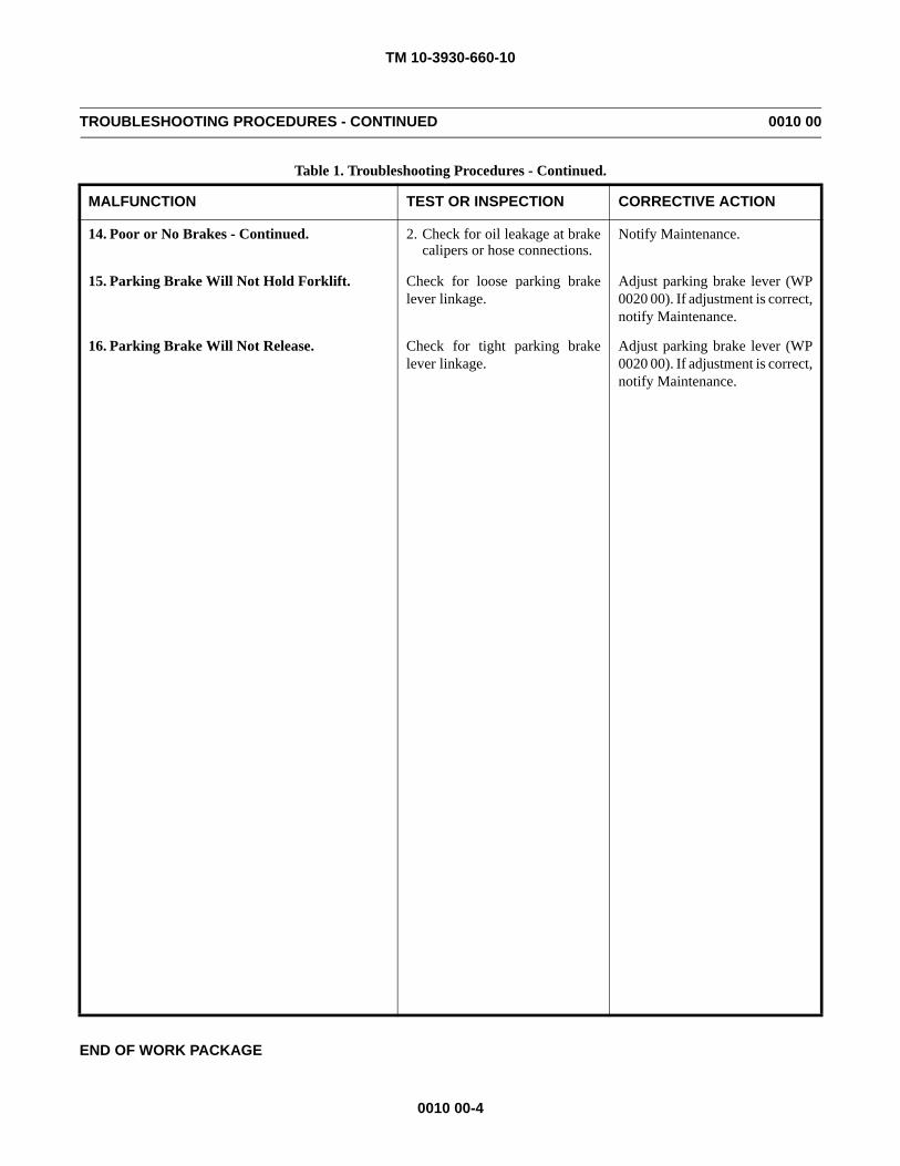
TM 10-3930-660-10
0010 00-4
TROUBLESHOOTING PROCEDURES - CONTINUED 0010 00
Table 1. Troubleshooting Procedures - Continued.
END OF WORK PACKAGE
MALFUNCTION TEST OR INSPECTION CORRECTIVE ACTION
14. Poor or No Brakes - Continued. 2. Check for oil leakage at brakecalipers or hose connections.
Notify Maintenance.
15. Parking Brake Will Not Hold Forklift. Check for loose parking brakelever linkage.
Adjust parking brake lever (WP0020 00). If adjustment is correct,notify Maintenance.
16. Parking Brake Will Not Release. Check for tight parking brakelever linkage.
Adjust parking brake lever (WP0020 00). If adjustment is correct,notify Maintenance.
TM 10-3930-660-10
CHAPTER 4OPERATOR MAINTENANCE INSTRUCTIONS

TM 10-3930-660-10
0011 00-1
PREVENTIVE MAINTENANCE CHECKS AND SERVICES (PMCS) INTRODUCTION 0011 00
GENERAL
1. To ensure that the 6K forklift is ready for operation at all times, it must be inspected on a regular basis so that defects maybe found and corrected before they result in injury or equipment failure or damage.
2. The PMCS Table in WP 0012 00 contains systematic instructions on inspections, lubrications, services, adjustments andcorrections to be performed by the operator to keep the forklift in good operating condition and ready for its primary mis-sion.
EXPLANATION OF TABLE ENTRIES
1. Item Number (Item No.) Column. Numbers in this column are for reference. When completing DA Form 2404 or DAForm 5988-E (Equipment Inspection and Maintenance Worksheet), include the item number for the check/service indicat-ing a fault. Item numbers also appear in the order that you must perform checks and services for the interval listed.
2. Interval Column. This column tells you when you must perform the procedure in the procedure column.
a. Before procedures must be done immediately before you operate the forklift.
b. During procedures must be done while you are operating the forklift.
c. After procedures must be done immediately after you have operated the forklift.
d. Weekly procedures must be done once each week.
e. Monthly procedures must be done once each month.
3. Man-Hours Column. This column indicates man-hours required to complete prescribed lubrication.
4. Location, Item to Check/Service Column. This column provides the location and item to be checked or serviced.
NOTEThe WARNINGs and CAUTIONs appearing in your PMCS table should always be observed. WARNINGsand CAUTIONs appear before applicable procedures. You must observe these WARNINGs to preventinjury to yourself and others, and CAUTIONs to prevent the forklift from being damaged.
5. Procedure Column. This column gives the procedure you must perform to check or service the item listed in the Item toCheck/Service column, to know if the forklift is ready or available for its intended mission. You must perform the proce-dure at the time stated in the interval column.
6. Not Fully Mission Capable If: Column. Information in this column tells you what faults will keep the forklift frombeing capable of performing its primary mission. If you perform check/service procedures that show faults listed in thiscolumn, the equipment is not mission-capable. Follow standard operating procedures for maintaining the equipment orreporting equipment failure.
GENERAL PMCS PROCEDURES
1. Always perform PMCS in the same order so it gets to be a habit. Once you've had some practice, you'll spot anythingwrong in a hurry. If the forklift does not perform as required, refer to the appropriate troubleshooting procedure in Chapter3.
2. If anything looks wrong and you can't fix it, write it on your DA Form 2404 or DA Form 5988-E. If you find somethingseriously wrong, IMMEDIATELY report it to supervisor.
3. Before performing preventive maintenance, read all the checks required for the applicable interval and prepare all that isneeded to make all the checks. You'll always need a rag or two.
TM 10-3930-660-10
0011 00-2
PREVENTIVE MAINTENANCE CHECKS AND SERVICES (PMCS) INTRODUCTION - CONTINUED 0011 00
GENERAL PMCS PROCEDURES - CONTINUED
WARNINGCleaning compound, solvent MIL-PRF-680 Type III is an environmentally compliant and low toxic mate-rial. However, it may be irritating to the eyes and skin. Use protective gloves and goggles. Use in well-ven-tilated areas. Keep away from open flames and other sources of ignition.
a. Keep It Clean. Dirt, grease, oil and debris get in the way and may cover up a serious problem. Clean as you work andas needed. Use cleaning compound, solvent (Item 2, WP 0025 00) on all metal surfaces. Use detergent (Item 3, WP0025 00) and water when you clean rubber, plastic and painted surfaces.
WARNINGWhen servicing forklift, performing maintenance or disposing of materials such as engine coolant, hydraulicfluid, lubricants, battery acids or batteries and CARC paint, consult your Field/local hazardous waste dis-posal center or safety office for local regulatory guidance. If further information is needed, please contactThe Army Environmental Hotline at 1-800-872-3845.
b. Hazardous Waste Disposal. Ensure all spills are cleaned up and disposed of IAW local policy and ordinances.
c. Rust and Corrosion. Check metal parts for rust and corrosion. If any bare metal or corrosion exists, clean and applya light coat of lubricating oil (Item 9, WP 0025 00). Report it to supervisor.
d. Bolts, Nuts and Screws. Check bolts, nuts and screws for obvious looseness, missing, bent or broken condition. Youcan't try them all with a tool, but look for chipped paint, bare metal or rust around bolt heads. If you find one is loose,notify supervisor.
e. Welds. Look for loose or chipped paint, rust or gaps where parts are welded together. If you find a bad weld, report itto supervisor.
f. Electric Wires and Connectors. Look for cracked or broken insulation, bare wires and loose or broken connectors.Reconnect loose connectors. Ensure that wires are in good condition.
g. Hoses and Fluid Lines. Look for wear, damage and signs of leaks. Check for loose clamps and fittings. Wet spotsindicate leaks, but a stain around a fitting or connector can also mean a leak. If a leak comes from a loose fitting orconnector, notify supervisor. If something is broken or worn out, report it to supervisor.
h. Fluid Leakage. It is necessary for you to know how fluid leakage affects the status of the forklift. The following aredefinitions of the types/classes of leakage you need to know to be able to determine the status of the forklift. Learnand be familiar with them, and remember - when in doubt, notify supervisor.
CAUTIONOperation is allowable with Class I and Class II leakage, EXCEPT for fuel, where NO leaks are allowed.WHEN IN DOUBT, NOTIFY SUPERVISOR. When operating with Class I or Class II leaks, check fluidlevels more frequently. Class III leaks must be reported immediately to supervisor. Failure to do this willresult in damage to forklift and/or components.
TM 10-3930-660-10
0011 00-3
PREVENTIVE MAINTENANCE CHECKS AND SERVICES (PMCS) INTRODUCTION - CONTINUED 0011 00
GENERAL PMCS PROCEDURES - CONTINUED
NOTENotify supervisor of any leaks you cannot fix.
Leakage Definitions for PMCS
Class I Leakage indicated by wetness or discoloration, but not great enough to formdrops.
Class II Leakage great enough to form drops, but not enough to cause drops to drip fromthe item being checked/inspected.
Class III Leakage great enough to form drops that fall from the item being checked/inspected.
GENERAL LUBRICATION PROCEDURES
NOTE• Lubrication instructions contained in this PMCS are MANDATORY.
• Overall view of lubrication points is located in the Lubrication Chart at the end of this work package. Localizedviews are located following the Lubrication Chart. Specific lubrication instructions are contained in the PMCSTable in WP 0012 00.
• Refer to FM 9-207 for lubrication in arctic operation.
1. Included in this PMCS are lubrication services to be performed by the operator.
2. Lubrication intervals are based on normal operation. Lubricate more during constant use and less during inactive periods.Use correct grade of lubricant for seasonal temperature expected. Refer to the KEY at the end of this work package.
3. For forklift under manufacturer’s warranty, hardtime intervals shall be followed. Shorten intervals if lubricants are knownto be contaminated or if operation is under adverse conditions (e.g., longer than usual operating hours, extended idlingperiods, extreme dust, etc.).
4. Keep all lubricants in a closed container and store in a clean, dry place away from extreme heat. Keep container coversclean and do not allow dust, dirt or other foreign material to mix with lubricants. Keep lubrication equipment clean andready for use.
WARNINGCleaning compound, solvent MIL-PRF-680 Type III is an environmentally compliant and low toxic mate-rial. However, it may be irritating to the eyes and skin. Use protective gloves and goggles. Use in well-ven-tilated areas. Keep away from open flames and other sources of ignition.
5. Clean area around lubrication points with cleaning compound, solvent (Item 2, WP 0025 00) or equivalent before lubricat-ing equipment. Keep all external parts of equipment not requiring lubrication free of lubricants. After lubrication, wipe offexcess lubricant to prevent accumulation of foreign matter.
6. Maintain a record of lubrication performed and report any problems noted during lubrication. Refer to DA PAM 738-750for forms and procedures to record and report any findings.
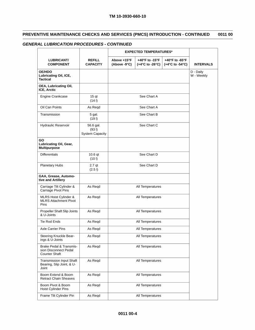
TM 10-3930-660-10
0011 00-4
PREVENTIVE MAINTENANCE CHECKS AND SERVICES (PMCS) INTRODUCTION - CONTINUED 0011 00
GENERAL LUBRICATION PROCEDURES - CONTINUED
LUBRICANT/COMPONENT
REFILLCAPACITY
EXPECTED TEMPERATURES*
INTERVALSAbove +15°F(Above -9°C)
+40°F to -15°F(+4°C to -26°C)
+40°F to -65°F(+4°C to -54°C)
OE/HDOLubricating Oil, ICE,Tactical
D - DailyW - Weekly
OEA, Lubricating Oil, ICE, Arctic
Engine Crankcase 15 qt(14 l)
See Chart A
Oil Can Points As Reqd See Chart A
Transmission 5 gal.(19 l)
See Chart B
Hydraulic Reservoir 56.6 gal.(93 l)
System Capacity
See Chart C
GOLubricating Oil, Gear, Multipurpose
Differentials 10.6 qt(10 l)
See Chart D
Planetary Hubs 2.7 qt(2.5 l)
See Chart D
GAA, Grease, Automo-tive and Artillery
Carriage Tilt Cylinder & Carriage Pivot Pins
As Reqd All Temperatures
MLRS Hoist Cylinder & MLRS Attachment Pivot Pins
As Reqd All Temperatures
Propeller Shaft Slip Joints & U-Joints
As Reqd All Temperatures
Tie Rod Ends As Reqd All Temperatures
Axle Carrier Pins As Reqd All Temperatures
Steering Knuckle Bear-ings & U-Joints
As Reqd All Temperatures
Brake Pedal & Transmis-sion Disconnect Pedal Counter Shaft
As Reqd All Temperatures
Transmission Input Shaft Bearing, Slip Joint, & U-Joint
As Reqd All Temperatures
Boom Extend & Boom Retract Chain Sheaves
As Reqd All Temperatures
Boom Pivot & Boom Hoist Cylinder Pins
As Reqd All Temperatures
Frame Tilt Cylinder Pin As Reqd All Temperatures
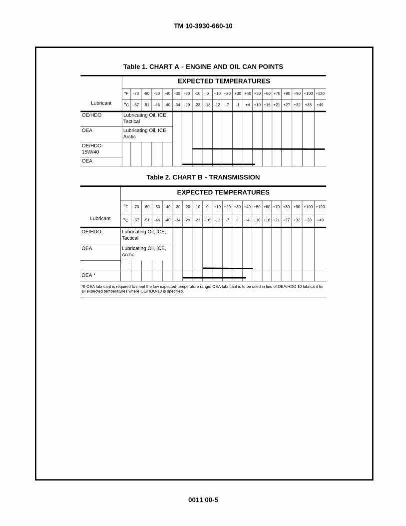
TM 10-3930-660-10
0011 00-5
Table 1. CHART A - ENGINE AND OIL CAN POINTS
EXPECTED TEMPERATURES
°F -70 -60 -50 -40 -30 -20 -10 0 +10 +20 +30 +40 +50 +60 +70 +80 +90 +100 +120
Lubricant °C -57 -51 -46 -40 -34 -29 -23 -18 -12 -7 -1 +4 +10 +16 +21 +27 +32 +38 +49
OE/HDO Lubricating Oil, ICE, Tactical
OEA Lubricating Oil, ICE, Arctic
OE/HDO-15W/40
OEA
Table 2. CHART B - TRANSMISSION
EXPECTED TEMPERATURES
°F -70 -60 -50 -40 -30 -20 -10 0 +10 +20 +30 +40 +50 +60 +70 +80 +90 +100 +120
Lubricant °C -57 -51 -46 -40 -34 -29 -23 -18 -12 -7 -1 +4 +10 +16 +21 +27 +32 +38 +49
OE/HDO Lubricating Oil, ICE, Tactical
OEA Lubricating Oil, ICE, Arctic
OEA *
*If OEA lubricant is required to meet the low expected-temperature range, OEA lubricant is to be used in lieu of OEA/HDO 10 lubricant for all expected temperatures where OE/HDO-10 is specified.
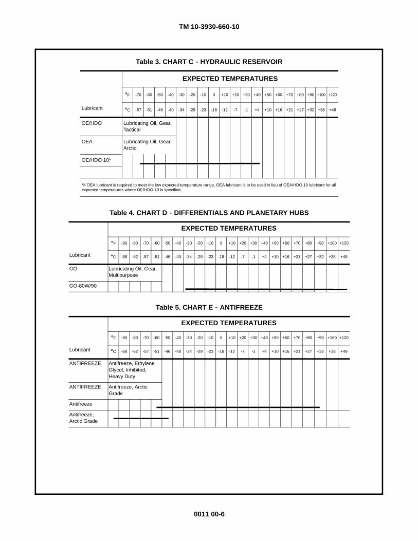
TM 10-3930-660-10
0011 00-6
Table 3. CHART C - HYDRAULIC RESERVOIR
EXPECTED TEMPERATURES
°F -70 -60 -50 -40 -30 -20 -10 0 +10 +20 +30 +40 +50 +60 +70 +80 +90 +100 +120
Lubricant °C -57 -51 -46 -40 -34 -29 -23 -18 -12 -7 -1 +4 +10 +16 +21 +27 +32 +38 +49
OE/HDO Lubricating Oil, Gear, Tactical
OEA Lubricating Oil, Gear, Arctic
OE/HDO 10*
*If OEA lubricant is required to meet the low expected-temperature range, OEA lubricant is to be used in lieu of OEA/HDO 10 lubricant for all expected temperatures where OE/HDO-10 is specified.
Table 4. CHART D - DIFFERENTIALS AND PLANETARY HUBS
EXPECTED TEMPERATURES
°F -90 -80 -70 -60 -50 -40 -30 -20 -10 0 +10 +20 +30 +40 +50 +60 +70 +80 +90 +100 +120
Lubricant °C -68 -62 -57 -51 -46 -40 -34 -29 -23 -18 -12 -7 -1 +4 +10 +16 +21 +27 +32 +38 +49
GO Lubricating Oil, Gear, Multipurpose
GO-80W/90
Table 5. CHART E - ANTIFREEZE
EXPECTED TEMPERATURES
°F -90 -80 -70 -60 -50 -40 -30 -20 -10 0 +10 +20 +30 +40 +50 +60 +70 +80 +90 +100 +120
Lubricant °C -68 -62 -57 -51 -46 -40 -34 -29 -23 -18 -12 -7 -1 +4 +10 +16 +21 +27 +32 +38 +49
ANTIFREEZE Antifreeze, Ethylene Glycol, Inhibited, Heavy Duty
ANTIFREEZE Antifreeze, Arctic Grade
Antifreeze
Antifreeze, Arctic Grade
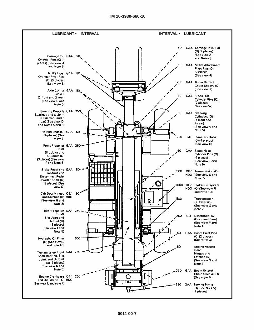
TM 10-3930-660-10
0011 00-7
LUBRICANT • INTERVAL INTERVAL • LUBRICANT
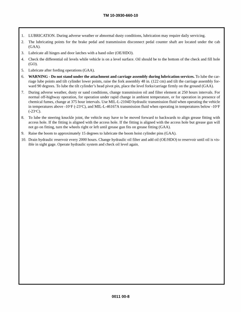
TM 10-3930-660-10
0011 00-8
1. LUBRICATION. During adverse weather or abnormal dusty conditions, lubrication may require daily servicing.2. The lubricating points for the brake pedal and transmission disconnect pedal counter shaft are located under the cab
(GAA).3. Lubricate all hinges and door latches with a hand oiler (OE/HDO).4. Check the differential oil levels while vehicle is on a level surface. Oil should be to the bottom of the check and fill hole
(GO).5. Lubricate after fording operations (GAA).6. WARNING - Do not stand under the attachment and carriage assembly during lubrication services. To lube the car-
riage lube points and tilt cylinder lower points, raise the fork assembly 48 in. (122 cm) and tilt the carriage assembly for-ward 90 degrees. To lube the tilt cylinder’s head pivot pin, place the level forks/carriage firmly on the ground (GAA).
7. During adverse weather, dusty or sand conditions, change transmission oil and filter element at 250 hours intervals. Fornormal off-highway operation, for operation under rapid change in ambient temperature, or for operation in presence ofchemical fumes, change at 375 hour intervals. Use MIL-L-2104D hydraulic transmission fluid when operating the vehiclein temperatures above -10°F (-23°C), and MIL-L-46167A transmission fluid when operating in temperatures below -10°F(-23°C).
8. To lube the steering knuckle joint, the vehicle may have to be moved forward to backwards to align grease fitting withaccess hole. If the fitting is aligned with the access hole. If the fitting is aligned with the access hole but grease gun willnot go on fitting, turn the wheels right or left until grease gun fits on grease fitting (GAA).
9. Raise the boom to approximately 15 degrees to lubricate the boom hoist cylinder pins (GAA).10. Drain hydraulic reservoir every 2000 hours. Change hydraulic oil filter and add oil (OE/HDO) to reservoir until oil is vis-
ible in sight gage. Operate hydraulic system and check oil level again.
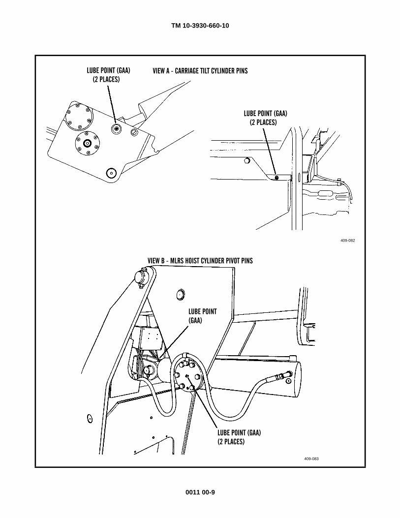
TM 10-3930-660-10
0011 00-9
VIEW A - CARRIAGE TILT CYLINDER PINS
LUBE POINT (GAA)(2 PLACES)
LUBE POINT (GAA)(2 PLACES)
409-082
LUBE POINT(GAA)
LUBE POINT (GAA)(2 PLACES)
409-083
VIEW B - MLRS HOIST CYLINDER PIVOT PINS
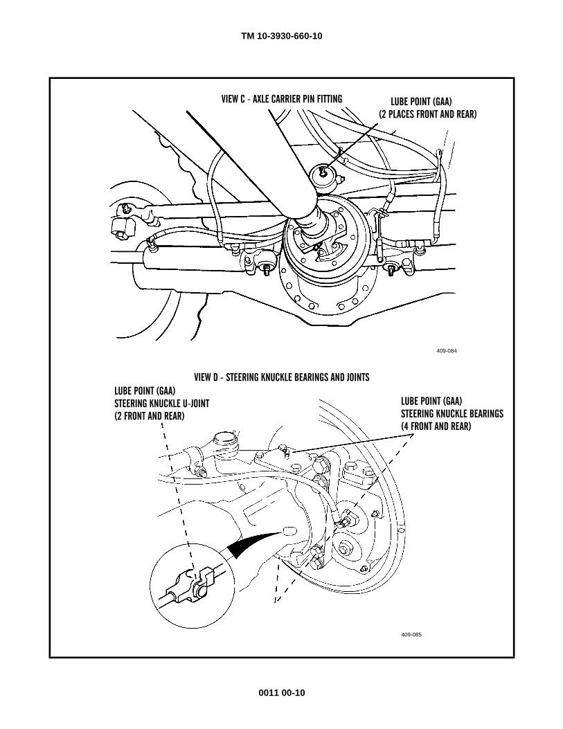
TM 10-3930-660-10
0011 00-10
VIEW C - AXLE CARRIER PIN FITTING LUBE POINT (GAA)(2 PLACES FRONT AND REAR)
409-084
LUBE POINT (GAA)STEERING KNUCKLE BEARINGS
409-085
VIEW D - STEERING KNUCKLE BEARINGS AND JOINTS
(4 FRONT AND REAR)
LUBE POINT (GAA)STEERING KNUCKLE U-JOINT(2 FRONT AND REAR)
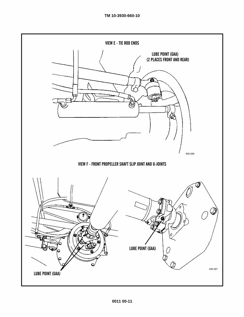
TM 10-3930-660-10
0011 00-11
VIEW E - TIE ROD ENDS
LUBE POINT (GAA)(2 PLACES FRONT AND REAR)
409-086
LUBE POINT (GAA)
409-087
VIEW F - FRONT PROPELLER SHAFT SLIP JOINT AND U-JOINTS
LUBE POINT (GAA)
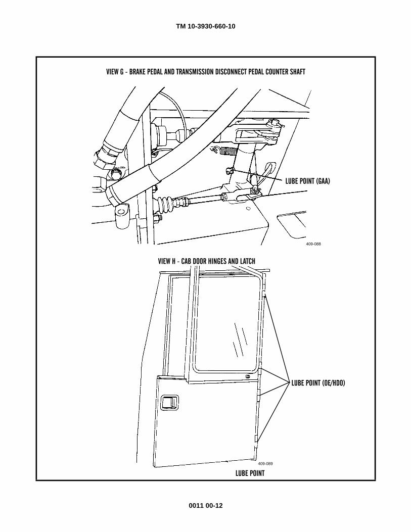
TM 10-3930-660-10
0011 00-12
VIEW G - BRAKE PEDAL AND TRANSMISSION DISCONNECT PEDAL COUNTER SHAFT
LUBE POINT (GAA)
409-088
LUBE POINT (OE/HDO)
409-089
VIEW H - CAB DOOR HINGES AND LATCH
LUBE POINT
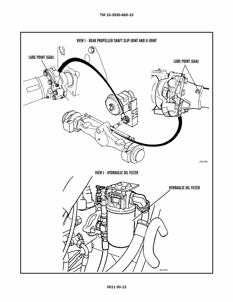
TM 10-3930-660-10
0011 00-13
VIEW I - REAR PROPELLER SHAFT SLIP JOINT AND U-JOINT
LUBE POINT (GAA)
409-090
LUBE POINT (GAA)
HYDRAULIC OIL FILTER
409-091
VIEW J - HYDRAULIC OIL FILTER
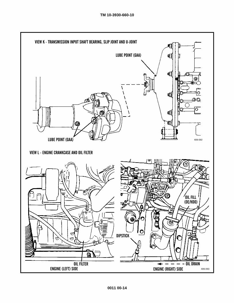
TM 10-3930-660-10
0011 00-14
VIEW K - TRANSMISSION INPUT SHAFT BEARING, SLIP JOINT AND U-JOINT
LUBE POINT (GAA)
409-092LUBE POINT (GAA)
OIL FILL
409-093
VIEW L - ENGINE CRANKCASE AND OIL FILTER
(OE/HDO)
OIL FILTER
DIPSTICK
ENGINE (RIGHT) SIDEENGINE (LEFT) SIDEOIL DRAIN
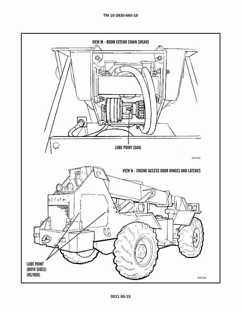
TM 10-3930-660-10
0011 00-15
VIEW M - BOOM EXTEND CHAIN SHEAVE
LUBE POINT (GAA)
409-094
LUBE POINT
409-095
VIEW N - ENGINE ACCESS DOOR HINGES AND LATCHES
(BOTH SIDES)(OE/HDO)
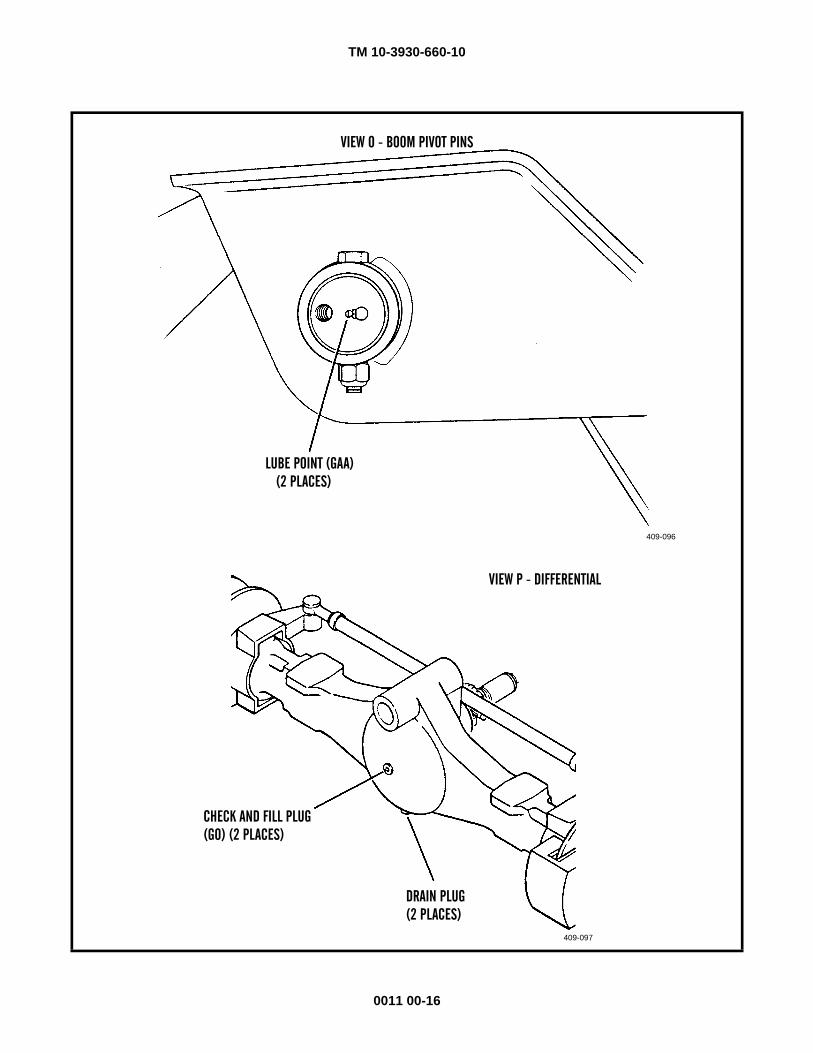
TM 10-3930-660-10
0011 00-16
VIEW O - BOOM PIVOT PINS
LUBE POINT (GAA)
409-096
(2 PLACES)
DRAIN PLUG
409-097
VIEW P - DIFFERENTIAL
CHECK AND FILL PLUG(GO) (2 PLACES)
(2 PLACES)
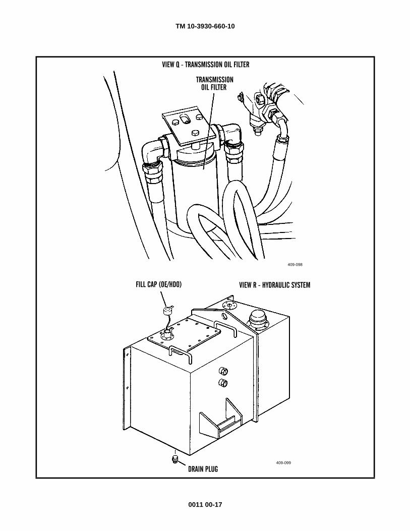
TM 10-3930-660-10
0011 00-17
TRANSMISSION
409-098
OIL FILTER
FILL CAP (OE/HDO)
409-099
VIEW R - HYDRAULIC SYSTEM
DRAIN PLUG
VIEW Q - TRANSMISSION OIL FILTER
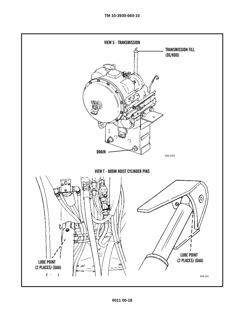
TM 10-3930-660-10
0011 00-18
VIEW S - TRANSMISSION
TRANSMISSION FILL
409-1915
(OE/HDO)
DRAIN
LUBE POINT
409-101
VIEW T - BOOM HOIST CYLINDER PINS
(2 PLACES) (GAA)
LUBE POINT(2 PLACES) (GAA)
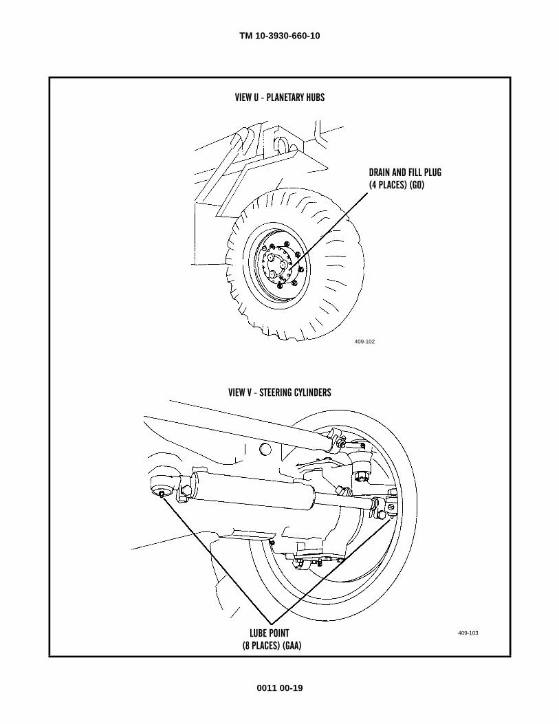
TM 10-3930-660-10
0011 00-19
VIEW U - PLANETARY HUBS
DRAIN AND FILL PLUG
409-102
(4 PLACES) (GO)
LUBE POINT 409-103
VIEW V - STEERING CYLINDERS
(8 PLACES) (GAA)
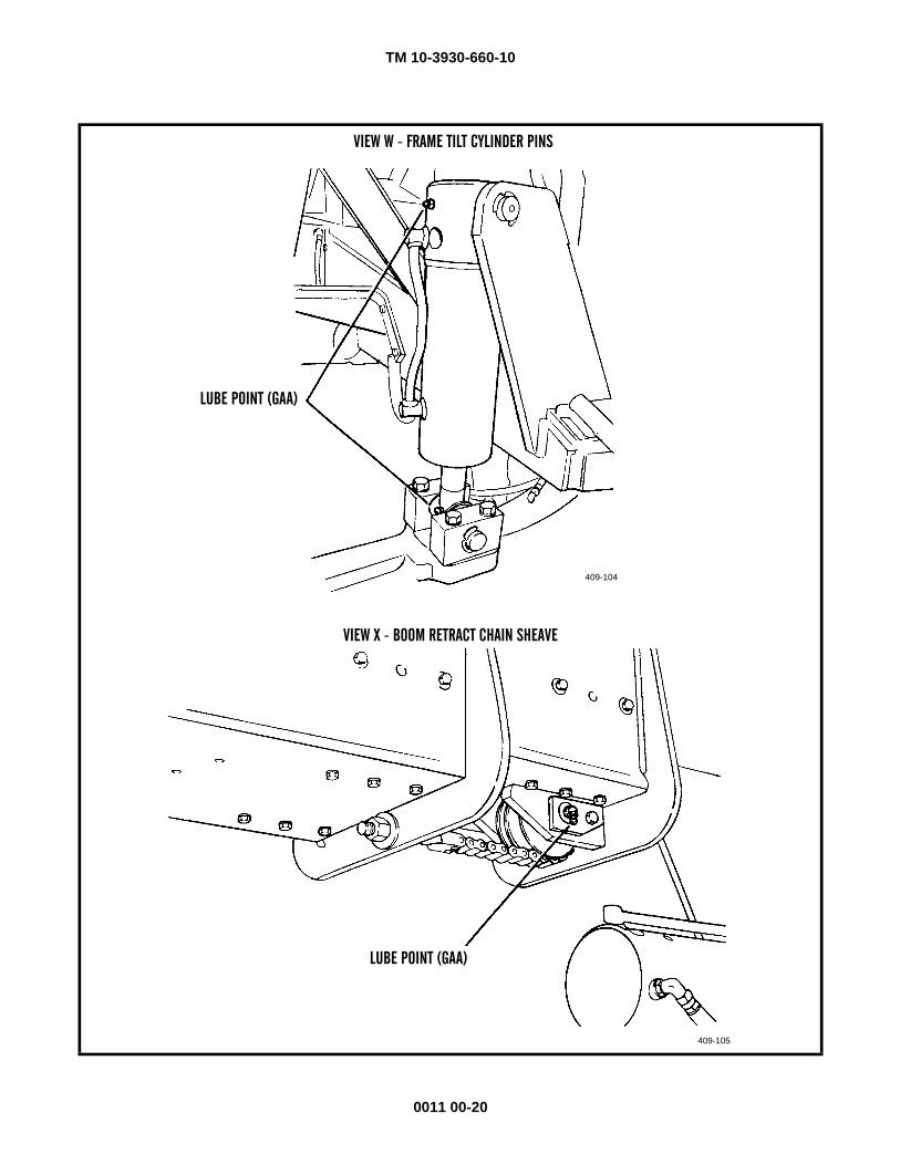
TM 10-3930-660-10
0011 00-20
409-104
LUBE POINT (GAA)
LUBE POINT (GAA)
409-105
VIEW X - BOOM RETRACT CHAIN SHEAVE
VIEW W - FRAME TILT CYLINDER PINS
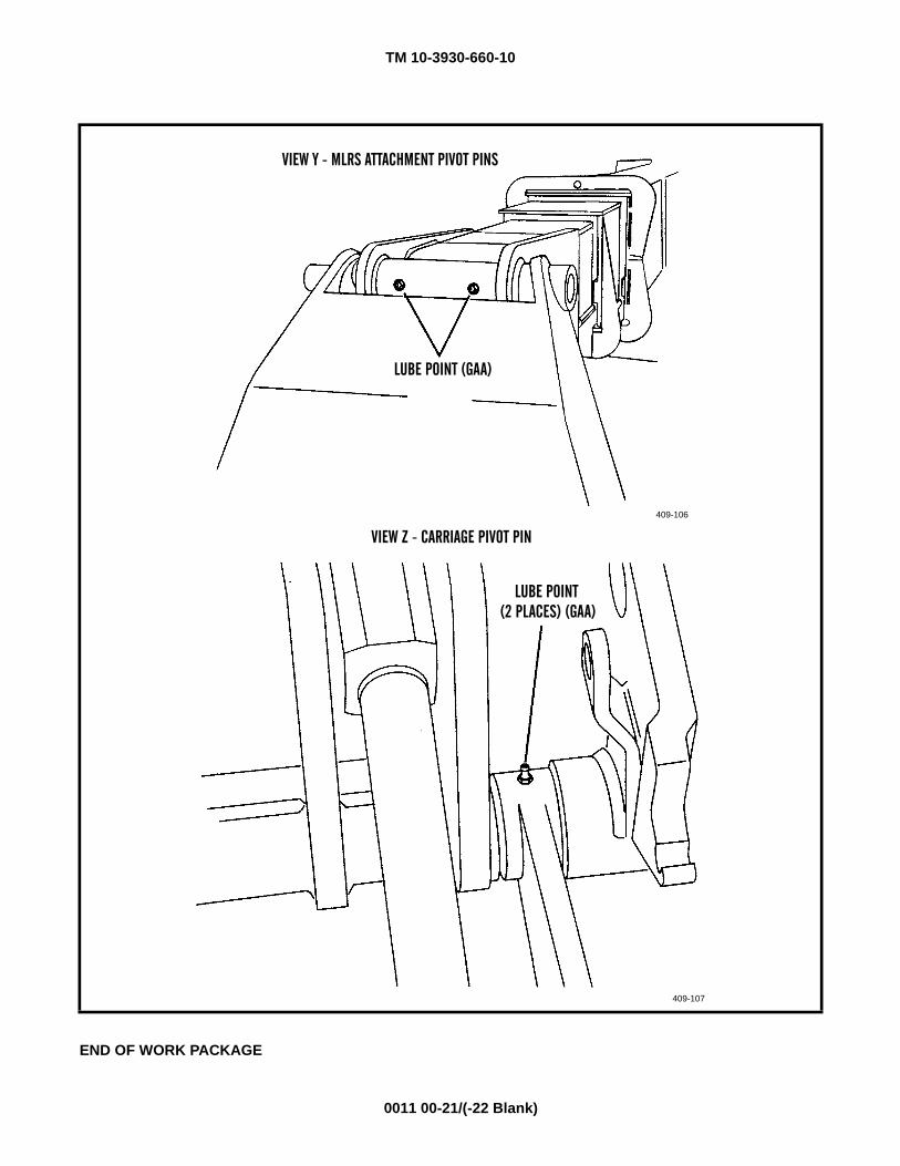
TM 10-3930-660-10
0011 00-21/(-22 Blank)
END OF WORK PACKAGE
VIEW Y - MLRS ATTACHMENT PIVOT PINS
409-106
LUBE POINT (GAA)
409-107
LUBE POINT(2 PLACES) (GAA)
VIEW Z - CARRIAGE PIVOT PIN

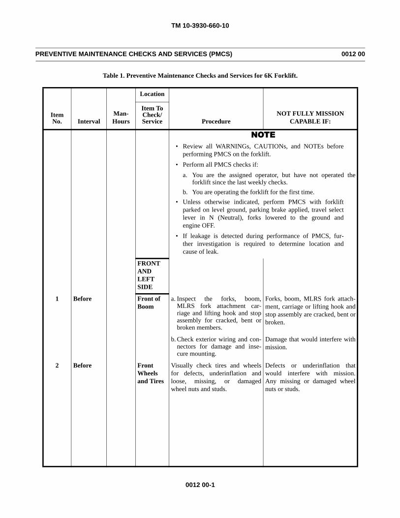
TM 10-3930-660-10
0012 00-1
PREVENTIVE MAINTENANCE CHECKS AND SERVICES (PMCS) 0012 00
Table 1. Preventive Maintenance Checks and Services for 6K Forklift.
Item No. Interval
Man-Hours
Location
ProcedureNOT FULLY MISSION
CAPABLE IF:
Item ToCheck/Service
NOTE• Review all WARNINGs, CAUTIONs, and NOTEs before
performing PMCS on the forklift.• Perform all PMCS checks if:
a. You are the assigned operator, but have not operated theforklift since the last weekly checks.
b. You are operating the forklift for the first time.• Unless otherwise indicated, perform PMCS with forklift
parked on level ground, parking brake applied, travel selectlever in N (Neutral), forks lowered to the ground andengine OFF.
• If leakage is detected during performance of PMCS, fur-ther investigation is required to determine location andcause of leak.
FRONT AND LEFT SIDE
1 Before Front of Boom
a. Inspect the forks, boom,MLRS fork attachment car-riage and lifting hook and stopassembly for cracked, bent orbroken members.
Forks, boom, MLRS fork attach-ment, carriage or lifting hook andstop assembly are cracked, bent orbroken.
b. Check exterior wiring and con-nectors for damage and inse-cure mounting.
Damage that would interfere withmission.
2 Before Front Wheels and Tires
Visually check tires and wheelsfor defects, underinflation andloose, missing, or damagedwheel nuts and studs.
Defects or underinflation thatwould interfere with mission.Any missing or damaged wheelnuts or studs.
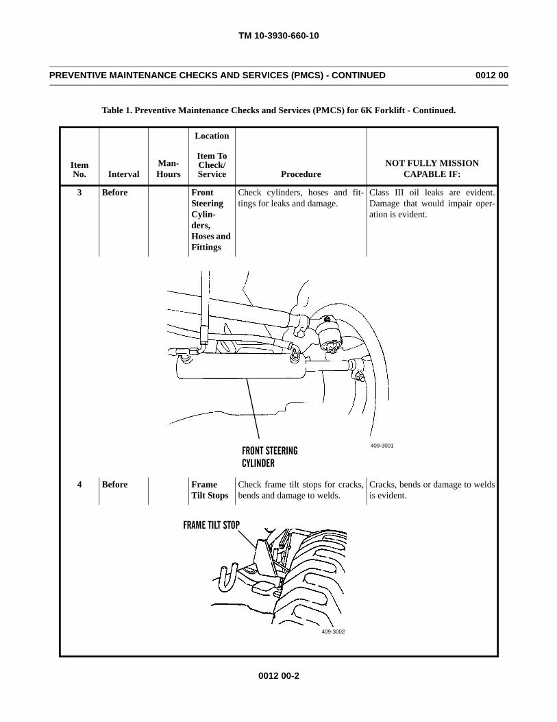
TM 10-3930-660-10
0012 00-2
PREVENTIVE MAINTENANCE CHECKS AND SERVICES (PMCS) - CONTINUED 0012 00
Table 1. Preventive Maintenance Checks and Services (PMCS) for 6K Forklift - Continued.
Item No. Interval
Man-Hours
Location
ProcedureNOT FULLY MISSION
CAPABLE IF:
Item ToCheck/Service
3 Before Front Steering Cylin-ders, Hoses and Fittings
Check cylinders, hoses and fit-tings for leaks and damage.
Class III oil leaks are evident.Damage that would impair oper-ation is evident.
4 Before Frame Tilt Stops
Check frame tilt stops for cracks,bends and damage to welds.
Cracks, bends or damage to weldsis evident.
409-3001FRONT STEERINGCYLINDER
409-3002
FRAME TILT STOP
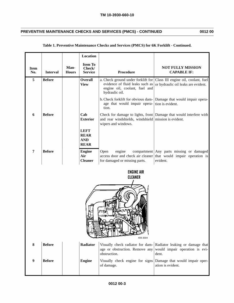
TM 10-3930-660-10
0012 00-3
PREVENTIVE MAINTENANCE CHECKS AND SERVICES (PMCS) - CONTINUED 0012 00
Table 1. Preventive Maintenance Checks and Services (PMCS) for 6K Forklift - Continued.
Item No. Interval
Man-Hours
Location
ProcedureNOT FULLY MISSION
CAPABLE IF:
Item ToCheck/Service
5 Before Overall View
a. Check ground under forklift forevidence of fluid leaks such asengine oil, coolant, fuel andhydraulic oil.
Class III engine oil, coolant, fuelor hydraulic oil leaks are evident.
b. Check forklift for obvious dam-age that would impair opera-tion.
Damage that would impair opera-tion is evident.
6 Before Cab Exterior
Check for damage to lights, frontand rear windshields, windshieldwipers and windows.
Damage that would interfere withmission is evident.
LEFT REAR AND REAR
7 Before EngineAirCleaner
Open engine compartmentaccess door and check air cleanerfor damaged or missing parts.
Any parts missing or damagedthat would impair operation isevident.
8 Before Radiator Visually check radiator for dam-age or obstruction. Remove anyobstruction.
Radiator leaking or damage thatwould impair operation is evi-dent.
9 Before Engine Visually check engine for signsof damage.
Damage that would impair oper-ation is evident.
409-3004
ENGINE AIRCLEANER
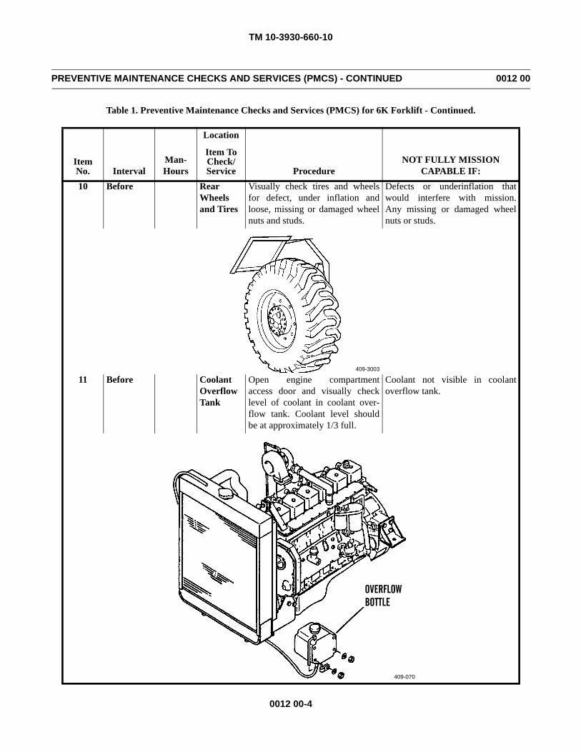
TM 10-3930-660-10
0012 00-4
PREVENTIVE MAINTENANCE CHECKS AND SERVICES (PMCS) - CONTINUED 0012 00
Table 1. Preventive Maintenance Checks and Services (PMCS) for 6K Forklift - Continued.
Item No. Interval
Man-Hours
Location
ProcedureNOT FULLY MISSION
CAPABLE IF:
Item ToCheck/Service
10 Before Rear Wheels and Tires
Visually check tires and wheelsfor defect, under inflation andloose, missing or damaged wheelnuts and studs.
Defects or underinflation thatwould interfere with mission.Any missing or damaged wheelnuts or studs.
11 Before Coolant Overflow Tank
Open engine compartmentaccess door and visually checklevel of coolant in coolant over-flow tank. Coolant level shouldbe at approximately 1/3 full.
Coolant not visible in coolantoverflow tank.
409-3003
409-070
OVERFLOWBOTTLE
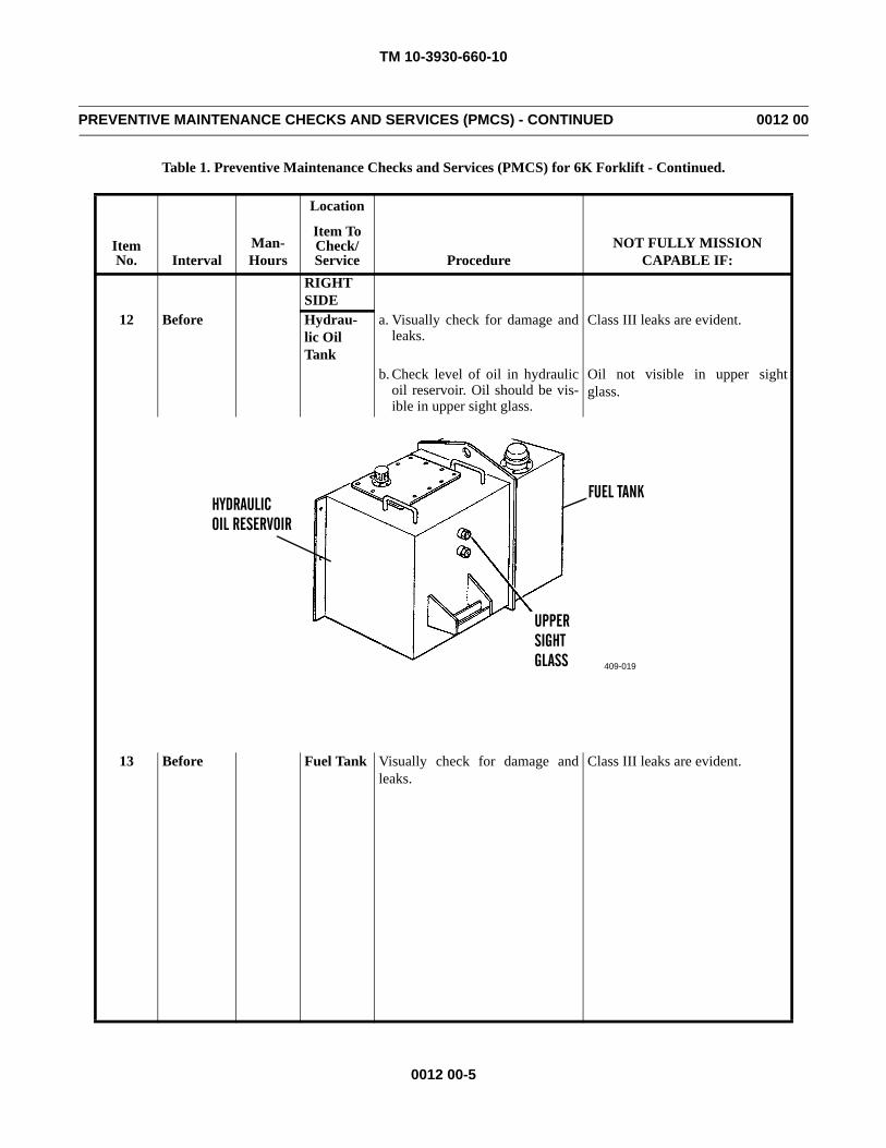
TM 10-3930-660-10
0012 00-5
PREVENTIVE MAINTENANCE CHECKS AND SERVICES (PMCS) - CONTINUED 0012 00
Table 1. Preventive Maintenance Checks and Services (PMCS) for 6K Forklift - Continued.
Item No. Interval
Man-Hours
Location
ProcedureNOT FULLY MISSION
CAPABLE IF:
Item ToCheck/Service
RIGHT SIDE
12 Before Hydrau-lic Oil Tank
a. Visually check for damage andleaks.
Class III leaks are evident.
b. Check level of oil in hydraulicoil reservoir. Oil should be vis-ible in upper sight glass.
Oil not visible in upper sightglass.
13 Before Fuel Tank Visually check for damage andleaks.
Class III leaks are evident.
409-019
UPPERSIGHTGLASS
OIL RESERVOIR
FUEL TANKHYDRAULIC
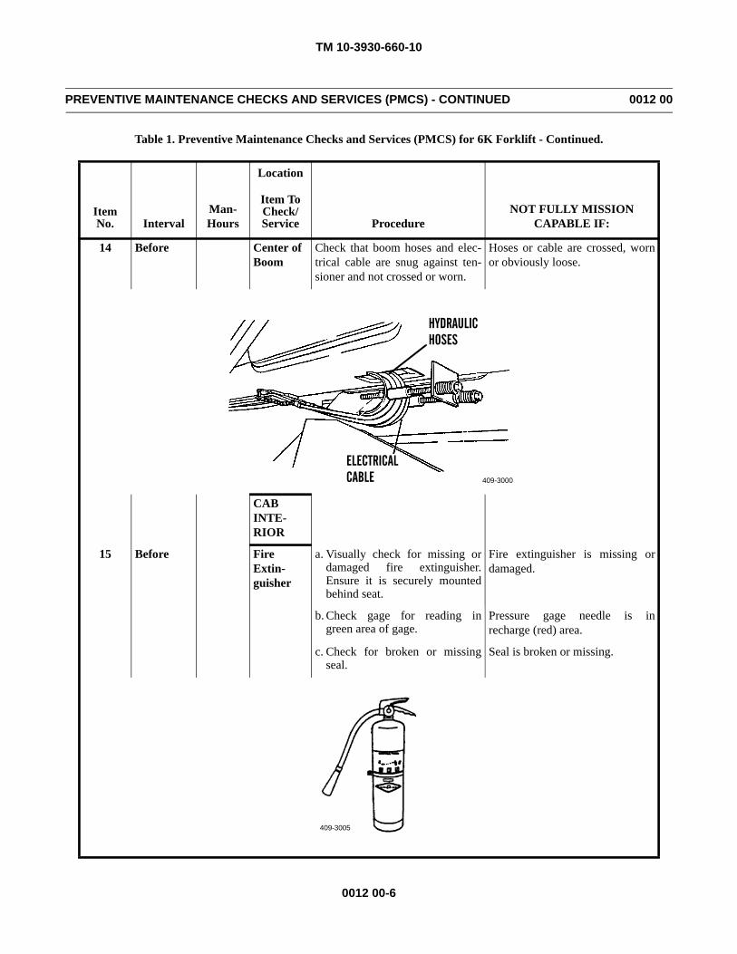
TM 10-3930-660-10
0012 00-6
PREVENTIVE MAINTENANCE CHECKS AND SERVICES (PMCS) - CONTINUED 0012 00
Table 1. Preventive Maintenance Checks and Services (PMCS) for 6K Forklift - Continued.
Item No. Interval
Man-Hours
Location
ProcedureNOT FULLY MISSION
CAPABLE IF:
Item ToCheck/Service
14 Before Center of Boom
Check that boom hoses and elec-trical cable are snug against ten-sioner and not crossed or worn.
Hoses or cable are crossed, wornor obviously loose.
CAB INTE-RIOR
15 Before Fire Extin-guisher
a. Visually check for missing ordamaged fire extinguisher.Ensure it is securely mountedbehind seat.
Fire extinguisher is missing ordamaged.
b. Check gage for reading ingreen area of gage.
Pressure gage needle is inrecharge (red) area.
c. Check for broken or missingseal.
Seal is broken or missing.
409-3000
ELECTRICALCABLE
HYDRAULICHOSES
409-3005
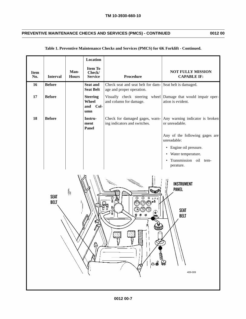
TM 10-3930-660-10
0012 00-7
PREVENTIVE MAINTENANCE CHECKS AND SERVICES (PMCS) - CONTINUED 0012 00
Table 1. Preventive Maintenance Checks and Services (PMCS) for 6K Forklift - Continued.
Item No. Interval
Man-Hours
Location
ProcedureNOT FULLY MISSION
CAPABLE IF:
Item ToCheck/Service
16 Before Seat and Seat Belt
Check seat and seat belt for dam-age and proper operation.
Seat belt is damaged.
17 Before SteeringWheeland Col-umn
Visually check steering wheeland column for damage.
Damage that would impair oper-ation is evident.
18 Before Instru-mentPanel
Check for damaged gages, warn-ing indicators and switches.
Any warning indicator is brokenor unreadable.
Any of the following gages areunreadable:
• Engine oil pressure.• Water temperature.• Transmission oil tem-
perature.
409-3006
SEATBELT
SEATBELT
409-009
INSTRUMENTPANEL
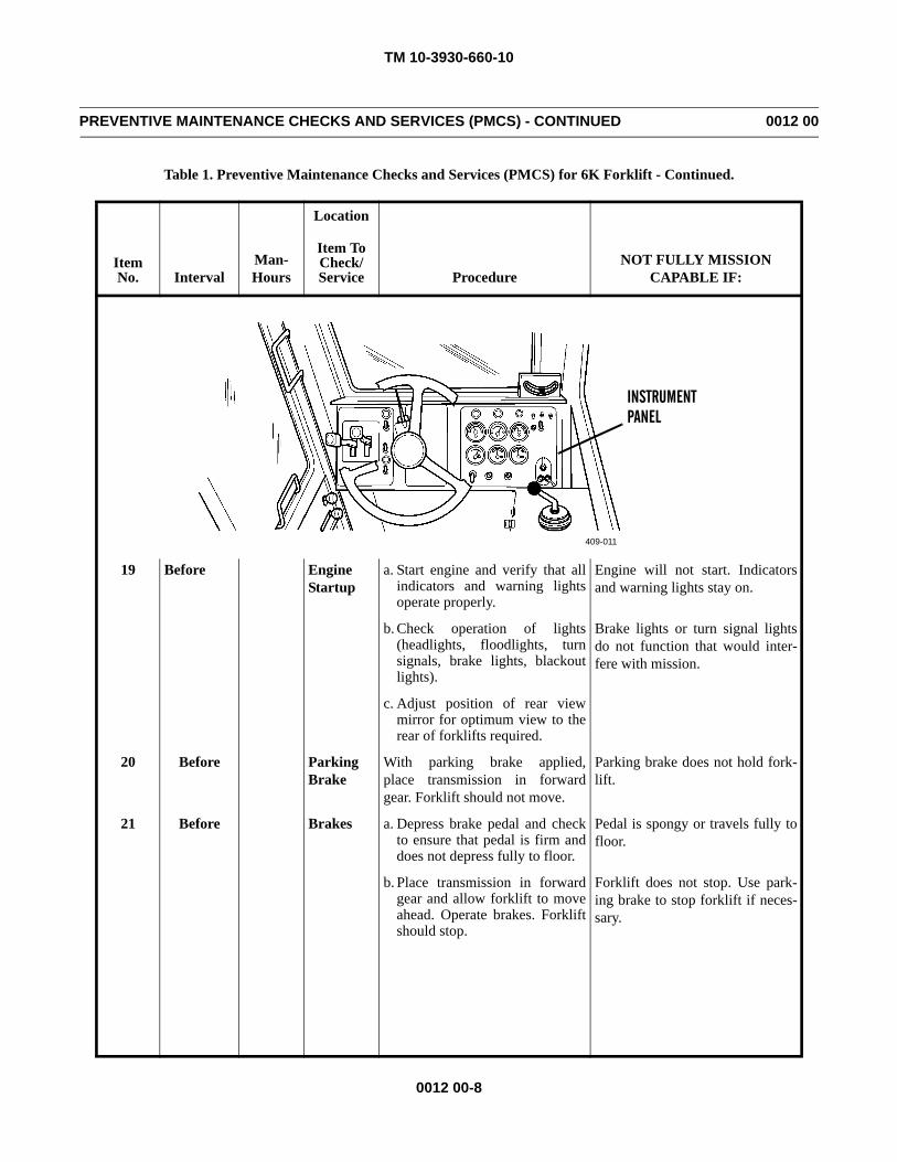
TM 10-3930-660-10
0012 00-8
PREVENTIVE MAINTENANCE CHECKS AND SERVICES (PMCS) - CONTINUED 0012 00
Table 1. Preventive Maintenance Checks and Services (PMCS) for 6K Forklift - Continued.
Item No. Interval
Man-Hours
Location
ProcedureNOT FULLY MISSION
CAPABLE IF:
Item ToCheck/Service
19 Before EngineStartup
a. Start engine and verify that allindicators and warning lightsoperate properly.
Engine will not start. Indicatorsand warning lights stay on.
b. Check operation of lights(headlights, floodlights, turnsignals, brake lights, blackoutlights).
Brake lights or turn signal lightsdo not function that would inter-fere with mission.
c. Adjust position of rear viewmirror for optimum view to therear of forklifts required.
20 Before Parking Brake
With parking brake applied,place transmission in forwardgear. Forklift should not move.
Parking brake does not hold fork-lift.
21 Before Brakes a. Depress brake pedal and checkto ensure that pedal is firm anddoes not depress fully to floor.
Pedal is spongy or travels fully tofloor.
b. Place transmission in forwardgear and allow forklift to moveahead. Operate brakes. Forkliftshould stop.
Forklift does not stop. Use park-ing brake to stop forklift if neces-sary.
409-011
INSTRUMENTPANEL
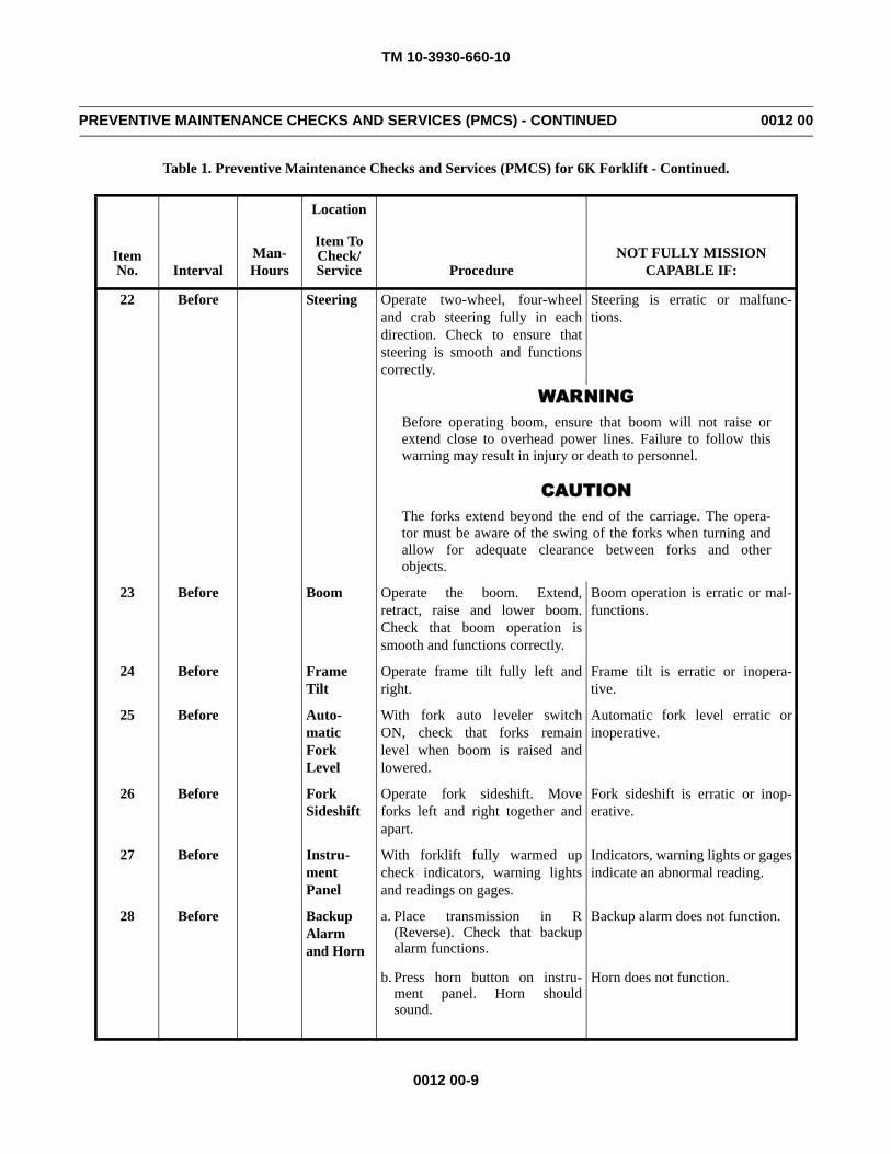
TM 10-3930-660-10
0012 00-9
PREVENTIVE MAINTENANCE CHECKS AND SERVICES (PMCS) - CONTINUED 0012 00
Table 1. Preventive Maintenance Checks and Services (PMCS) for 6K Forklift - Continued.
Item No. Interval
Man-Hours
Location
ProcedureNOT FULLY MISSION
CAPABLE IF:
Item ToCheck/Service
22 Before Steering Operate two-wheel, four-wheeland crab steering fully in eachdirection. Check to ensure thatsteering is smooth and functionscorrectly.
Steering is erratic or malfunc-tions.
WARNINGBefore operating boom, ensure that boom will not raise orextend close to overhead power lines. Failure to follow thiswarning may result in injury or death to personnel.
CAUTIONThe forks extend beyond the end of the carriage. The opera-tor must be aware of the swing of the forks when turning andallow for adequate clearance between forks and otherobjects.
23 Before Boom Operate the boom. Extend,retract, raise and lower boom.Check that boom operation issmooth and functions correctly.
Boom operation is erratic or mal-functions.
24 Before Frame Tilt
Operate frame tilt fully left andright.
Frame tilt is erratic or inopera-tive.
25 Before Auto-matic Fork Level
With fork auto leveler switchON, check that forks remainlevel when boom is raised andlowered.
Automatic fork level erratic orinoperative.
26 Before Fork Sideshift
Operate fork sideshift. Moveforks left and right together andapart.
Fork sideshift is erratic or inop-erative.
27 Before Instru-ment Panel
With forklift fully warmed upcheck indicators, warning lightsand readings on gages.
Indicators, warning lights or gagesindicate an abnormal reading.
28 Before Backup Alarm and Horn
a. Place transmission in R(Reverse). Check that backupalarm functions.
Backup alarm does not function.
b. Press horn button on instru-ment panel. Horn shouldsound.
Horn does not function.
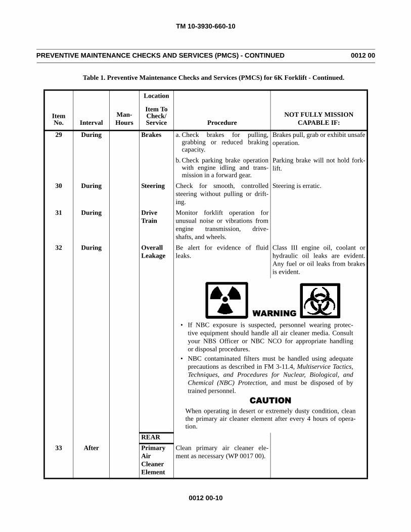
TM 10-3930-660-10
0012 00-10
PREVENTIVE MAINTENANCE CHECKS AND SERVICES (PMCS) - CONTINUED 0012 00
Table 1. Preventive Maintenance Checks and Services (PMCS) for 6K Forklift - Continued.
Item No. Interval
Man-Hours
Location
ProcedureNOT FULLY MISSION
CAPABLE IF:
Item ToCheck/Service
29 During Brakes a. Check brakes for pulling,grabbing or reduced brakingcapacity.
Brakes pull, grab or exhibit unsafeoperation.
b. Check parking brake operationwith engine idling and trans-mission in a forward gear.
Parking brake will not hold fork-lift.
30 During Steering Check for smooth, controlledsteering without pulling or drift-ing.
Steering is erratic.
31 During Drive Train
Monitor forklift operation forunusual noise or vibrations fromengine transmission, drive-shafts, and wheels.
32 During Overall Leakage
Be alert for evidence of fluidleaks.
Class III engine oil, coolant orhydraulic oil leaks are evident.Any fuel or oil leaks from brakesis evident.
WARNING• If NBC exposure is suspected, personnel wearing protec-
tive equipment should handle all air cleaner media. Consultyour NBS Officer or NBC NCO for appropriate handlingor disposal procedures.
• NBC contaminated filters must be handled using adequateprecautions as described in FM 3-11.4, Multiservice Tactics,Techniques, and Procedures for Nuclear, Biological, andChemical (NBC) Protection, and must be disposed of bytrained personnel.
CAUTIONWhen operating in desert or extremely dusty condition, cleanthe primary air cleaner element after every 4 hours of opera-tion.
REAR33 After Primary
Air Cleaner Element
Clean primary air cleaner ele-ment as necessary (WP 0017 00).
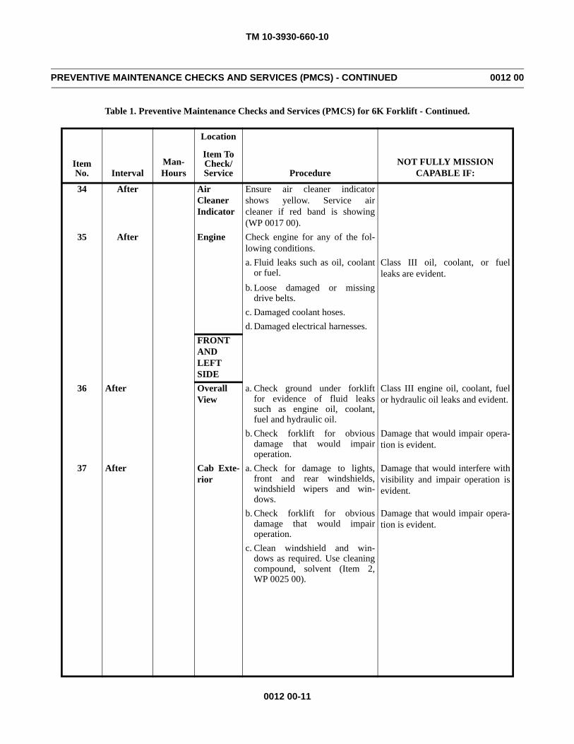
TM 10-3930-660-10
0012 00-11
PREVENTIVE MAINTENANCE CHECKS AND SERVICES (PMCS) - CONTINUED 0012 00
Table 1. Preventive Maintenance Checks and Services (PMCS) for 6K Forklift - Continued.
Item No. Interval
Man-Hours
Location
ProcedureNOT FULLY MISSION
CAPABLE IF:
Item ToCheck/Service
34 After Air Cleaner Indicator
Ensure air cleaner indicatorshows yellow. Service aircleaner if red band is showing(WP 0017 00).
35 After Engine Check engine for any of the fol-lowing conditions.a. Fluid leaks such as oil, coolant
or fuel.Class III oil, coolant, or fuelleaks are evident.
b. Loose damaged or missingdrive belts.
c. Damaged coolant hoses.d. Damaged electrical harnesses.
FRONT AND LEFT SIDE
36 After OverallView
a. Check ground under forkliftfor evidence of fluid leakssuch as engine oil, coolant,fuel and hydraulic oil.
Class III engine oil, coolant, fuelor hydraulic oil leaks and evident.
b. Check forklift for obviousdamage that would impairoperation.
Damage that would impair opera-tion is evident.
37 After Cab Exte-rior
a. Check for damage to lights,front and rear windshields,windshield wipers and win-dows.
Damage that would interfere withvisibility and impair operation isevident.
b. Check forklift for obviousdamage that would impairoperation.
Damage that would impair opera-tion is evident.
c. Clean windshield and win-dows as required. Use cleaningcompound, solvent (Item 2,WP 0025 00).
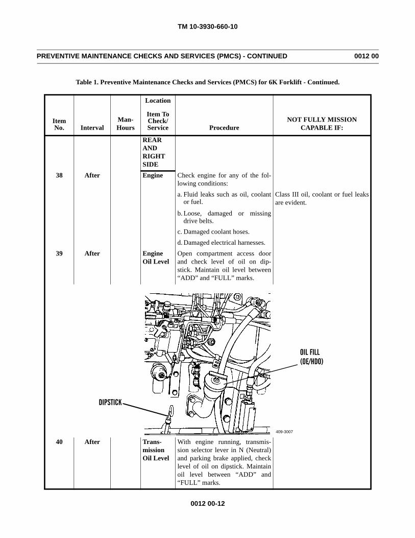
TM 10-3930-660-10
0012 00-12
PREVENTIVE MAINTENANCE CHECKS AND SERVICES (PMCS) - CONTINUED 0012 00
Table 1. Preventive Maintenance Checks and Services (PMCS) for 6K Forklift - Continued.
Item No. Interval
Man-Hours
Location
ProcedureNOT FULLY MISSION
CAPABLE IF:
Item ToCheck/Service
REAR AND RIGHT SIDE
38 After Engine Check engine for any of the fol-lowing conditions:a. Fluid leaks such as oil, coolant
or fuel.Class III oil, coolant or fuel leaksare evident.
b. Loose, damaged or missingdrive belts.
c. Damaged coolant hoses.d. Damaged electrical harnesses.
39 After Engine Oil Level
Open compartment access doorand check level of oil on dip-stick. Maintain oil level between“ADD” and “FULL” marks.
40 After Trans-mission Oil Level
With engine running, transmis-sion selector lever in N (Neutral)and parking brake applied, checklevel of oil on dipstick. Maintainoil level between “ADD” and“FULL” marks.
409-3007
OIL FILL(OE/HDO)
DIPSTICK
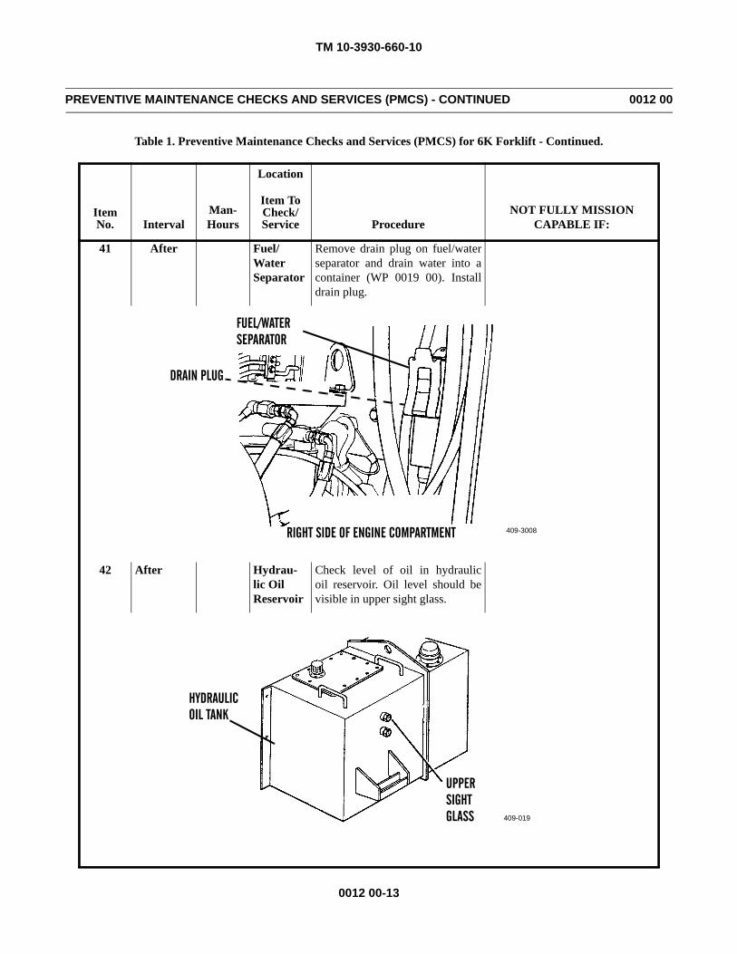
TM 10-3930-660-10
0012 00-13
PREVENTIVE MAINTENANCE CHECKS AND SERVICES (PMCS) - CONTINUED 0012 00
Table 1. Preventive Maintenance Checks and Services (PMCS) for 6K Forklift - Continued.
Item No. Interval
Man-Hours
Location
ProcedureNOT FULLY MISSION
CAPABLE IF:
Item ToCheck/Service
41 After Fuel/ Water Separator
Remove drain plug on fuel/waterseparator and drain water into acontainer (WP 0019 00). Installdrain plug.
42 After Hydrau-lic OilReservoir
Check level of oil in hydraulicoil reservoir. Oil level should bevisible in upper sight glass.
409-3008
DRAIN PLUG
FUEL/WATERSEPARATOR
RIGHT SIDE OF ENGINE COMPARTMENT
409-019
UPPERSIGHTGLASS
HYDRAULICOIL TANK
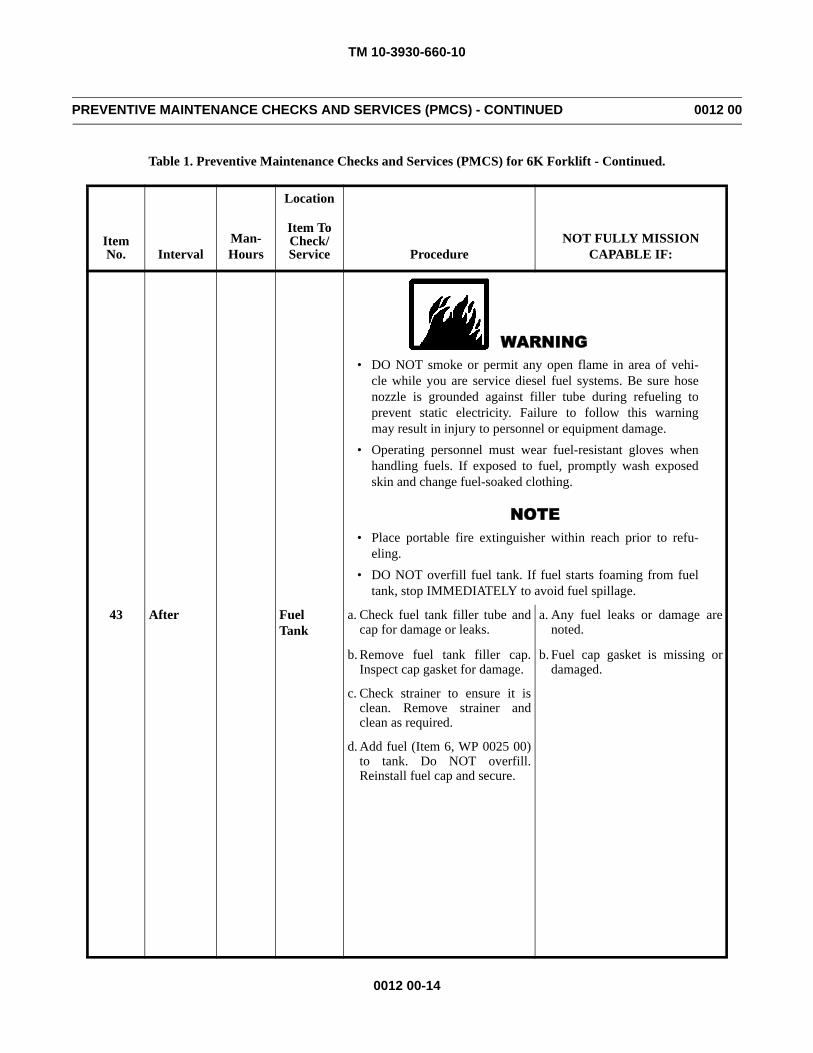
TM 10-3930-660-10
0012 00-14
PREVENTIVE MAINTENANCE CHECKS AND SERVICES (PMCS) - CONTINUED 0012 00
Table 1. Preventive Maintenance Checks and Services (PMCS) for 6K Forklift - Continued.
Item No. Interval
Man-Hours
Location
ProcedureNOT FULLY MISSION
CAPABLE IF:
Item ToCheck/Service
WARNING• DO NOT smoke or permit any open flame in area of vehi-
cle while you are service diesel fuel systems. Be sure hosenozzle is grounded against filler tube during refueling toprevent static electricity. Failure to follow this warningmay result in injury to personnel or equipment damage.
• Operating personnel must wear fuel-resistant gloves whenhandling fuels. If exposed to fuel, promptly wash exposedskin and change fuel-soaked clothing.
NOTE• Place portable fire extinguisher within reach prior to refu-
eling.• DO NOT overfill fuel tank. If fuel starts foaming from fuel
tank, stop IMMEDIATELY to avoid fuel spillage.
43 After FuelTank
a. Check fuel tank filler tube andcap for damage or leaks.
a. Any fuel leaks or damage arenoted.
b. Remove fuel tank filler cap.Inspect cap gasket for damage.
b. Fuel cap gasket is missing ordamaged.
c. Check strainer to ensure it isclean. Remove strainer andclean as required.
d. Add fuel (Item 6, WP 0025 00)to tank. Do NOT overfill.Reinstall fuel cap and secure.
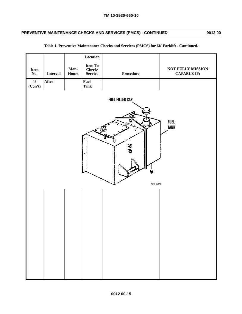
TM 10-3930-660-10
0012 00-15
PREVENTIVE MAINTENANCE CHECKS AND SERVICES (PMCS) - CONTINUED 0012 00
Table 1. Preventive Maintenance Checks and Services (PMCS) for 6K Forklift - Continued.
Item No. Interval
Man-Hours
Location
ProcedureNOT FULLY MISSION
CAPABLE IF:
Item ToCheck/Service
43(Con’t)
After FuelTank
409-3009
FUELTANK
FUEL FILLER CAP
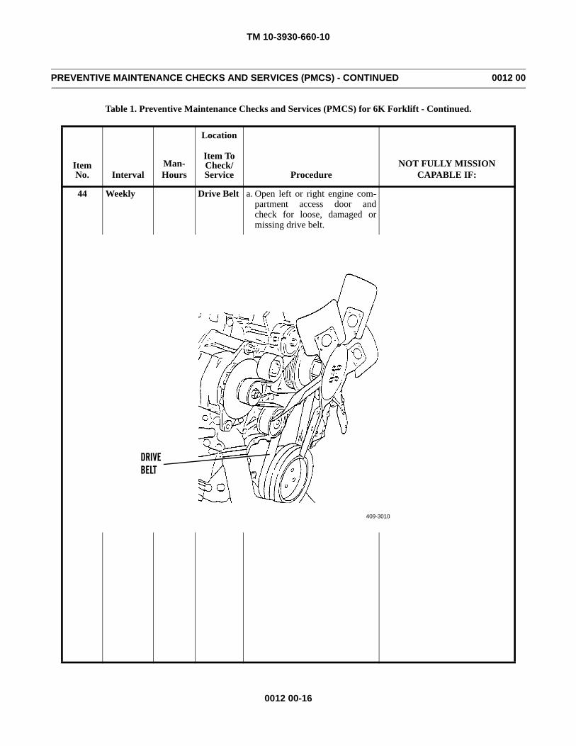
TM 10-3930-660-10
0012 00-16
PREVENTIVE MAINTENANCE CHECKS AND SERVICES (PMCS) - CONTINUED 0012 00
Table 1. Preventive Maintenance Checks and Services (PMCS) for 6K Forklift - Continued.
Item No. Interval
Man-Hours
Location
ProcedureNOT FULLY MISSION
CAPABLE IF:
Item ToCheck/Service
44 Weekly Drive Belt a. Open left or right engine com-partment access door andcheck for loose, damaged ormissing drive belt.
409-3010
DRIVEBELT
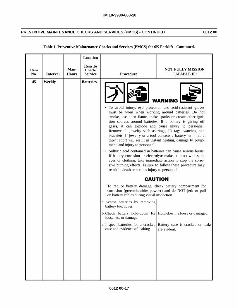
TM 10-3930-660-10
0012 00-17
PREVENTIVE MAINTENANCE CHECKS AND SERVICES (PMCS) - CONTINUED 0012 00
Table 1. Preventive Maintenance Checks and Services (PMCS) for 6K Forklift - Continued.
Item No. Interval
Man-Hours
Location
ProcedureNOT FULLY MISSION
CAPABLE IF:
Item ToCheck/Service
45 Weekly Batteries
WARNING• To avoid injury, eye protection and acid-resistant gloves
must be worn when working around batteries. Do notsmoke, use open flame, make sparks or create other igni-tion sources around batteries, If a battery is giving offgases, it can explode and cause injury to personnel.Remove all jewelry such as rings, ID tags, watches, andbracelets. If jewelry or a tool contacts a battery terminal, adirect short will result in instant heating, damage to equip-ment, and injury to personnel.
• Sulfuric acid contained in batteries can cause serious burns.If battery corrosion or electrolyte makes contact with skin,eyes or clothing, take immediate action to stop the corro-sive burning effects. Failure to follow these procedure mayresult in death or serious injury to personnel.
CAUTIONTo reduce battery damage, check battery compartment forcorrosion (greenish/white powder) and do NOT jerk or pullon battery cables during visual inspection.
a. Access batteries by removingbattery box cover.
b. Check battery hold-down forlooseness or damage.
Hold-down is loose or damaged.
c. Inspect batteries for a crackedcase and evidence of leaking.
Battery case is cracked or leaksare evident.
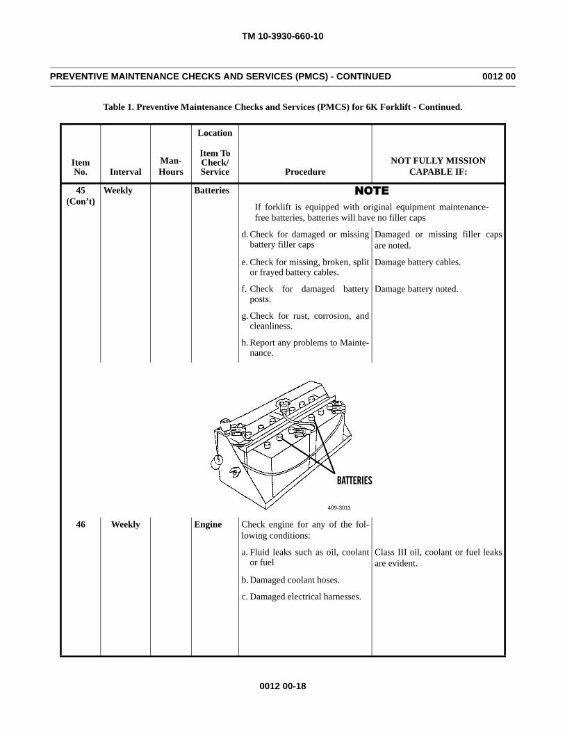
TM 10-3930-660-10
0012 00-18
PREVENTIVE MAINTENANCE CHECKS AND SERVICES (PMCS) - CONTINUED 0012 00
Table 1. Preventive Maintenance Checks and Services (PMCS) for 6K Forklift - Continued.
Item No. Interval
Man-Hours
Location
ProcedureNOT FULLY MISSION
CAPABLE IF:
Item ToCheck/Service
45(Con’t)
Weekly Batteries NOTEIf forklift is equipped with original equipment maintenance-free batteries, batteries will have no filler caps
d. Check for damaged or missingbattery filler caps
Damaged or missing filler capsare noted.
e. Check for missing, broken, splitor frayed battery cables.
Damage battery cables.
f. Check for damaged batteryposts.
Damage battery noted.
g. Check for rust, corrosion, andcleanliness.
h. Report any problems to Mainte-nance.
46 Weekly Engine Check engine for any of the fol-lowing conditions:
a. Fluid leaks such as oil, coolantor fuel
Class III oil, coolant or fuel leaksare evident.
b. Damaged coolant hoses.
c. Damaged electrical harnesses.
409-3011
BATTERIES
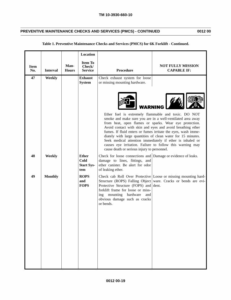
TM 10-3930-660-10
0012 00-19
PREVENTIVE MAINTENANCE CHECKS AND SERVICES (PMCS) - CONTINUED 0012 00
Table 1. Preventive Maintenance Checks and Services (PMCS) for 6K Forklift - Continued.
Item No. Interval
Man-Hours
Location
ProcedureNOT FULLY MISSION
CAPABLE IF:
Item ToCheck/Service
47 Weekly Exhaust System
Check exhaust system for looseor missing mounting hardware.
WARNINGEther fuel is extremely flammable and toxic. DO NOTsmoke and make sure you are in a well-ventilated area awayfrom heat, open flames or sparks. Wear eye protection.Avoid contact with skin and eyes and avoid breathing etherfumes. If fluid enters or fumes irritate the eyes, wash imme-diately with large quantities of clean water for 15 minutes.Seek medical attention immediately if ether is inhaled orcauses eye irritation. Failure to follow this warning maycause death or serious injury to personnel.
48 Weekly Ether Cold Start Sys-tem
Check for loose connections anddamage to lines, fittings, andether canister. Be alert for odorof leaking ether.
Damage or evidence of leaks.
49 Monthly ROPS and FOPS
Check cab Roll Over ProtectiveStructure (ROPS) Falling ObjectProtective Structure (FOPS) andforklift frame for loose or miss-ing mounting hardware andobvious damage such as cracksor bends.
Loose or missing mounting hard-ware. Cracks or bends are evi-dent.
TM 10-3930-660-10
0012 00-20
PREVENTIVE MAINTENANCE CHECKS AND SERVICES (PMCS) - CONTINUED 0012 00
Table 1. Preventive Maintenance Checks and Services (PMCS) for 6K Forklift - Continued.
Item No. Interval
Man-Hours
Location
ProcedureNOT FULLY MISSION
CAPABLE IF:
Item ToCheck/Service
CAUTIONDo NOT exercise vehicle when temperature is below 0°F(-18°C).
NOTEPerform the following exercise procedure after completionof all Before, After, Weekly, and Monthly PMCS.Do NOT exercise forklift if it has been operated within thepast month.
50 Monthly All Sys-tems Exercise
a. Start engine and run at idle forfive minutes.
b. While forklift is warming up,perform a walk around inspec-tion, checking for evidence ofleaks.
Class III oil, coolant or hydraulicleaks are evident. Any brake fluidor fuel leaks are evident.
NOTEIf temperature is below 32°F (0°C), operate controls for 15minutes prior to moving vehicle.
c. After forklift has idled for fiveminutes, begin to operate allcontrols slowly:• Transmission in all
ranges.• Brakes and parking brake
applied and released.• Steering in two-wheel,
four-wheel and crab in F(forward) and in R(reverse).
TM 10-3930-660-10
0012 00-21/(-22 Blank)
PREVENTIVE MAINTENANCE CHECKS AND SERVICES (PMCS) - CONTINUED 0012 00
Table 1. Preventive Maintenance Checks and Services (PMCS) for 6K Forklift - Continued.
END OF WORK PACKAGE
Item No. Interval
Man-Hours
Location
ProcedureNOT FULLY MISSION
CAPABLE IF:
Item ToCheck/Service
50(Con’t)
Monthly All Sys-tems Exercise
WARNINGBefore operating boom, ensure that boom will not raise orextend close to overhead power lines. Failure to follow thiswarning may result in injury or death to personnel.
CAUTIONThe forks extend beyond the end of the carriage. The opera-tor must be aware of the swing of the forks when turning andallow for adequate clearance between forks and otherobjects.
• Boom in extend andretract, raise and lower.
• Frame tilt in fully leftand right.
• Forks in left and right,together and apart.

TM 10-3930-660-10
0013 00-1/(-2 Blank)
GENERAL MAINTENANCE INSTRUCTIONS 0013 00
INSPECTION OF COMPONENTS
1. Clean all parts before inspection. Check for defects such as physical distortion, wear, cracks and pitting.
2. Check all hose surfaces for broken or frayed fabric, breaks caused by sharp kinks or chafing against other parts of theunit. Inspect metal tubing lines for kinks. Inspect fitting threads for damage. Replace any defective parts. Check forleaks after assembly and during initial operation period.
3. Visually inspect all castings and weldments for cracks.
4. Inspect all wiring for chafed or burned insulation. Inspect all terminal connectors for loose connections and brokenparts.
CLEANING PROCEDURES
1. For exterior cleaning of frame and structural components, use detergent (Item 3, WP 0025 00) in a solution as recom-mended on the container. Leave application on surface for approximately 10 minutes before rinsing. Rinse with hot orcold water under pressure. If available, use hot water under 80-120 lb (551-827 kPa) pressure. An ordinary garden hosemay be used if no other equipment is available. If pressurized water supply is not available, wash painted surfaces witha solution of 1/4 cup soap (Item 15, WP 0025 00) to one gallon of water.
WARNINGCleaning compound, solvent MIL-PRF-680 Type III is an environmentally compliant and low toxic mate-rial. However, it may be irritating to the eyes and skin. Use protective gloves and goggles. Use in well-ven-tilated areas. Keep away from open flames and other sources of ignition.
NOTE
Do not use dielectric grease on electrical connectors.
2. Electrical parts such as coils, connectors, switches and insulating wiring shall not be soaked or sprayed with cleaningsolutions. Clean these parts with a clean, dry cloth moistened with cleaning compound, solvent (Item 2, WP 0025 00).
REMOVAL OF COMPONENTS
1. Ensure that adequate clearance is available for removal of component. Disassemble 6K forklift to extent necessary toprovide adequate working clearance.
2. Remove parts only when service is required. Do not disassemble a component further than necessary to accomplish ser-vice.
ASSEMBLY AND INSTALLATION
Ensure that all parts are clean and dry before installation. If you lose or damage a component during servicing,notify supervisor.
END OF WORK PACKAGE

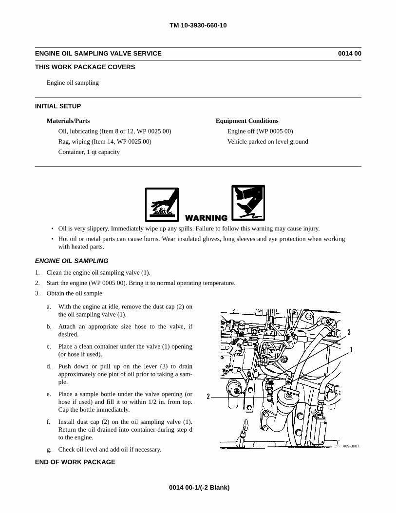
TM 10-3930-660-10
0014 00-1/(-2 Blank)
ENGINE OIL SAMPLING VALVE SERVICE 0014 00
THIS WORK PACKAGE COVERS
Engine oil sampling
INITIAL SETUP
Materials/PartsOil, lubricating (Item 8 or 12, WP 0025 00)Rag, wiping (Item 14, WP 0025 00)Container, 1 qt capacity
Equipment ConditionsEngine off (WP 0005 00)Vehicle parked on level ground
WARNING• Oil is very slippery. Immediately wipe up any spills. Failure to follow this warning may cause injury.• Hot oil or metal parts can cause burns. Wear insulated gloves, long sleeves and eye protection when working
with heated parts.
ENGINE OIL SAMPLING
1. Clean the engine oil sampling valve (1).2. Start the engine (WP 0005 00). Bring it to normal operating temperature.3. Obtain the oil sample.
a. With the engine at idle, remove the dust cap (2) onthe oil sampling valve (1).
b. Attach an appropriate size hose to the valve, ifdesired.
c. Place a clean container under the valve (1) opening(or hose if used).
d. Push down or pull up on the lever (3) to drainapproximately one pint of oil prior to taking a sam-ple.
e. Place a sample bottle under the valve opening (orhose if used) and fill it to within 1/2 in. from top.Cap the bottle immediately.
f. Install dust cap (2) on the oil sampling valve (1).Return the oil drained into container during step dto the engine.
g. Check oil level and add oil if necessary.
END OF WORK PACKAGE
409-3007
2
3
1

TM 10-3930-660-10
0015 00-1
HYDRAULIC OIL SAMPLING VALVE SERVICE 0015 00
THIS WORK PACKAGE COVERS
Hydraulic oil sampling
INITIAL SETUP
Materials/PartsOil, lubricating (Item 8 or 11, WP 0025 00)Rag, wiping (Item 14, WP 0025 00)Container, 1 qt capacity
Equipment ConditionsEngine off (WP 0005 00)Vehicle parked on level ground
WARNING• Oil is very slippery. Immediately wipe up any spills. Failure to follow this warning may cause injury.• Hot oil or metal parts can cause burns. Wear insulated gloves, long sleeves and eye protection when working
with heated parts.
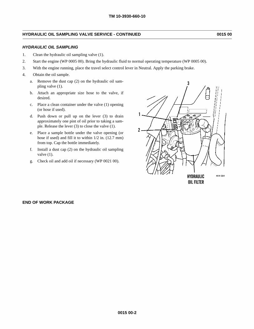
TM 10-3930-660-10
0015 00-2
HYDRAULIC OIL SAMPLING VALVE SERVICE - CONTINUED 0015 00
HYDRAULIC OIL SAMPLING
1. Clean the hydraulic oil sampling valve (1).2. Start the engine (WP 0005 00). Bring the hydraulic fluid to normal operating temperature (WP 0005 00).3. With the engine running, place the travel select control lever in Neutral. Apply the parking brake.4. Obtain the oil sample.
a. Remove the dust cap (2) on the hydraulic oil sam-pling valve (1).
b. Attach an appropriate size hose to the valve, ifdesired.
c. Place a clean container under the valve (1) opening(or hose if used).
d. Push down or pull up on the lever (3) to drainapproximately one pint of oil prior to taking a sam-ple. Release the lever (3) to close the valve (1).
e. Place a sample bottle under the valve opening (orhose if used) and fill it to within 1/2 in. (12.7 mm)from top. Cap the bottle immediately.
f. Install a dust cap (2) on the hydraulic oil samplingvalve (1).
g. Check oil and add oil if necessary (WP 0021 00).
END OF WORK PACKAGE
HYDRAULICOIL FILTER
1
2
3
TM 10-3930-660-10
0016 00-1
TRANSMISSION OIL SAMPLING VALVE SERVICE 0016 00
THIS WORK PACKAGE COVERS
Transmission oil sampling
Materials/PartsOil, lubricating (Item 8 or 11, WP 0025 00)Rag, wiping (Item 15, WP 0025 00)Container, 1 qt capacity
Equipment ConditionsEngine off (WP 0005 00)Vehicle parked on level ground
WARNING• Oil is very slippery. Immediately wipe up any spills. Failure to follow this warning may cause injury.• Hot oil or metal parts can cause burns. Wear insulated gloves, long sleeves and eye protection when working
with heated parts.
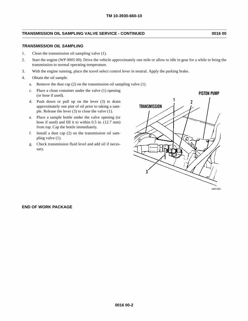
TM 10-3930-660-10
0016 00-2
TRANSMISSION OIL SAMPLING VALVE SERVICE - CONTINUED 0016 00
TRANSMISSION OIL SAMPLING
1. Clean the transmission oil sampling valve (1).2. Start the engine (WP 0005 00). Drive the vehicle approximately one mile or allow to idle in gear for a while to bring the
transmission to normal operating temperature.3. With the engine running, place the travel select control lever in neutral. Apply the parking brake.4. Obtain the oil sample.
a. Remove the dust cap (2) on the transmission oil sampling valve (1).c. Place a clean container under the valve (1) opening
(or hose if used).d. Push down or pull up on the lever (3) to drain
approximately one pint of oil prior to taking a sam-ple. Release the lever (3) to close the valve (1).
e. Place a sample bottle under the valve opening (orhose if used) and fill it to within 0.5 in. (12.7 mm)from top. Cap the bottle immediately.
f. Install a dust cap (2) on the transmission oil sam-pling valve (1).
g. Check transmission fluid level and add oil if neces-sary.
END OF WORK PACKAGE
409-063
TRANSMISSION
PISTON PUMP
3
1 2
409-063
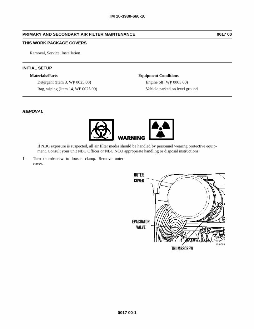
TM 10-3930-660-10
0017 00-1
PRIMARY AND SECONDARY AIR FILTER MAINTENANCE 0017 00
THIS WORK PACKAGE COVERS
Removal, Service, Installation
INITIAL SETUP
Materials/PartsDetergent (Item 3, WP 0025 00)Rag, wiping (Item 14, WP 0025 00)
Equipment ConditionsEngine off (WP 0005 00)Vehicle parked on level ground
REMOVAL
WARNINGIf NBC exposure is suspected, all air filter media should be handled by personnel wearing protective equip-ment. Consult your unit NBC Officer or NBC NCO appropriate handling or disposal instructions.
1. Turn thumbscrew to loosen clamp. Remove outercover.
409-069
OUTERCOVER
THUMBSCREW
EVACUATORVALVE
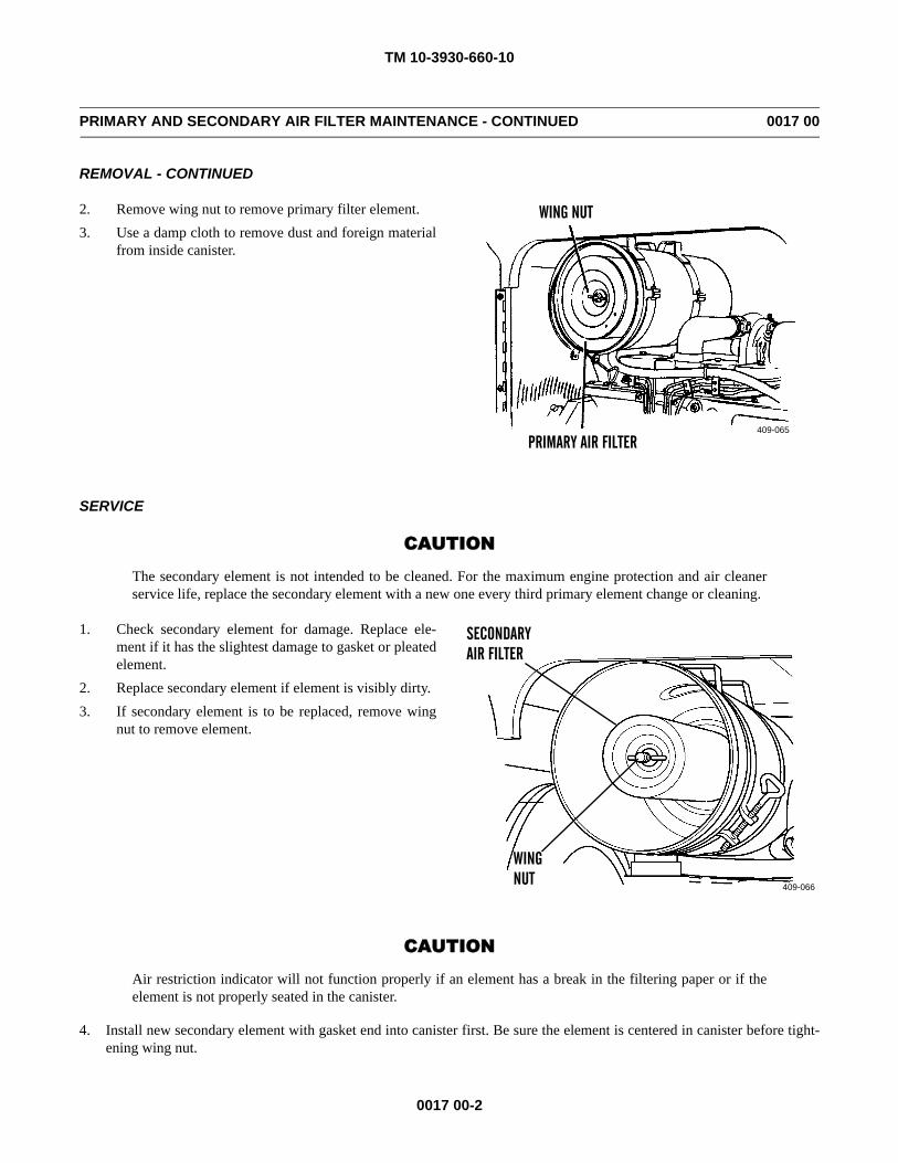
TM 10-3930-660-10
0017 00-2
PRIMARY AND SECONDARY AIR FILTER MAINTENANCE - CONTINUED 0017 00
REMOVAL - CONTINUED
2. Remove wing nut to remove primary filter element.3. Use a damp cloth to remove dust and foreign material
from inside canister.
SERVICE
CAUTION
The secondary element is not intended to be cleaned. For the maximum engine protection and air cleanerservice life, replace the secondary element with a new one every third primary element change or cleaning.
1. Check secondary element for damage. Replace ele-ment if it has the slightest damage to gasket or pleatedelement.
2. Replace secondary element if element is visibly dirty.3. If secondary element is to be replaced, remove wing
nut to remove element.
CAUTION
Air restriction indicator will not function properly if an element has a break in the filtering paper or if theelement is not properly seated in the canister.
4. Install new secondary element with gasket end into canister first. Be sure the element is centered in canister before tight-ening wing nut.
409-065
WING NUT
PRIMARY AIR FILTER
409-066
SECONDARYAIR FILTER
WINGNUT
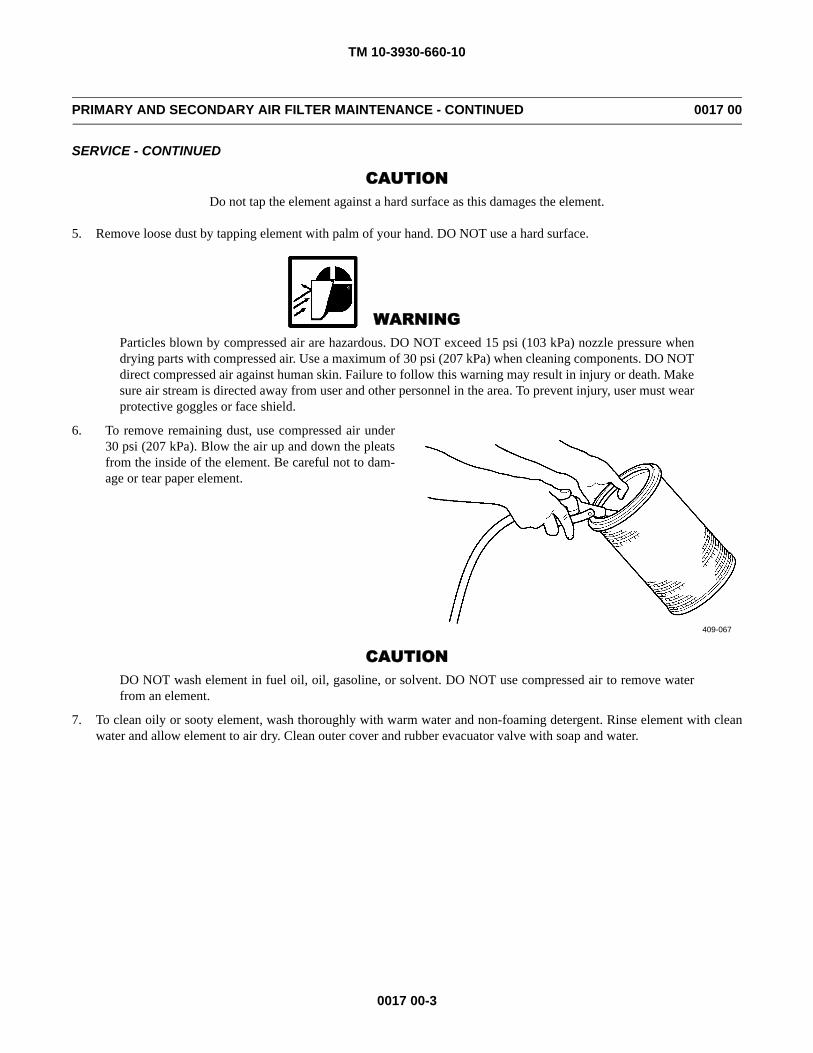
TM 10-3930-660-10
0017 00-3
PRIMARY AND SECONDARY AIR FILTER MAINTENANCE - CONTINUED 0017 00
SERVICE - CONTINUED
CAUTIONDo not tap the element against a hard surface as this damages the element.
5. Remove loose dust by tapping element with palm of your hand. DO NOT use a hard surface.
WARNINGParticles blown by compressed air are hazardous. DO NOT exceed 15 psi (103 kPa) nozzle pressure whendrying parts with compressed air. Use a maximum of 30 psi (207 kPa) when cleaning components. DO NOTdirect compressed air against human skin. Failure to follow this warning may result in injury or death. Makesure air stream is directed away from user and other personnel in the area. To prevent injury, user must wearprotective goggles or face shield.
6. To remove remaining dust, use compressed air under30 psi (207 kPa). Blow the air up and down the pleatsfrom the inside of the element. Be careful not to dam-age or tear paper element.
CAUTIONDO NOT wash element in fuel oil, oil, gasoline, or solvent. DO NOT use compressed air to remove waterfrom an element.
7. To clean oily or sooty element, wash thoroughly with warm water and non-foaming detergent. Rinse element with cleanwater and allow element to air dry. Clean outer cover and rubber evacuator valve with soap and water.
409-067
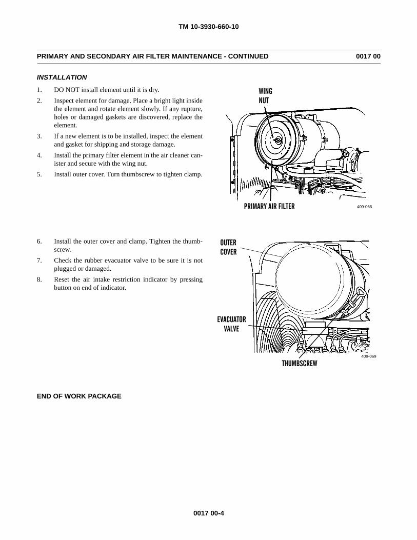
TM 10-3930-660-10
0017 00-4
PRIMARY AND SECONDARY AIR FILTER MAINTENANCE - CONTINUED 0017 00
INSTALLATION
1. DO NOT install element until it is dry.2. Inspect element for damage. Place a bright light inside
the element and rotate element slowly. If any rupture,holes or damaged gaskets are discovered, replace theelement.
3. If a new element is to be installed, inspect the elementand gasket for shipping and storage damage.
4. Install the primary filter element in the air cleaner can-ister and secure with the wing nut.
5. Install outer cover. Turn thumbscrew to tighten clamp.
6. Install the outer cover and clamp. Tighten the thumb-screw.
7. Check the rubber evacuator valve to be sure it is notplugged or damaged.
8. Reset the air intake restriction indicator by pressingbutton on end of indicator.
END OF WORK PACKAGE
409-065
WINGNUT
PRIMARY AIR FILTER
409-069
OUTERCOVER
THUMBSCREW
EVACUATORVALVE
TM 10-3930-660-10
0018 00-1
ENGINE COOLANT CHECK AND FILL 0018 00
THIS WORK PACKAGE COVERS
Check and Fill
INITIAL SETUP
Materials/PartsAntifreeze (Item 1, WP 0025 00)Rag, wiping (Item 14, WP 0025 00)
Equipment ConditionsEngine off (WP 0005 00)Vehicle parked on level ground
WARNING• DO NOT service cooling system unless engine has cooled. This is a pressurized cooling system and
escaping steam or hot coolant may cause burns.• DO NOT remove radiator cap when engine is hot. Allow engine to cool down. Loosen cap to first stop
and let any pressure out of cooling system, then remove cap. Failure to follow this warning may causeburns.
• Wear effective eye, glove, and skin protection when handling coolants. Failure to do so may causeinjury.
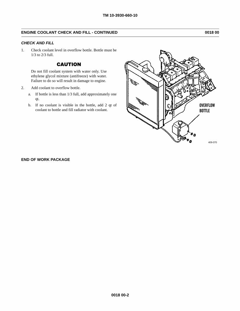
TM 10-3930-660-10
0018 00-2
ENGINE COOLANT CHECK AND FILL - CONTINUED 0018 00
CHECK AND FILL
1. Check coolant level in overflow bottle. Bottle must be1/3 to 2/3 full.
CAUTIONDo not fill coolant system with water only. Useethylene glycol mixture (antifreeze) with water.Failure to do so will result in damage to engine.
2. Add coolant to overflow bottle.a. If bottle is less than 1/3 full, add approximately one
qt.b. If no coolant is visible in the bottle, add 2 qt of
coolant to bottle and fill radiator with coolant.
END OF WORK PACKAGE
409-070
OVERFLOWBOTTLE
TM 10-3930-660-10
0019 00-1
FUEL/WATER SEPARATOR SERVICE 0019 00
THIS WORK PACKAGE COVERS
Drain
INITIAL SETUP
Materials/PartsContainer, 1 qt capacity
Equipment ConditionsEngine off (WP 0005 00)Vehicle parked on level ground
WARNING• DO NOT perform fuel system checks, inspections or maintenance while smoking or near fire, flames or
sparks. Fuel may ignite, causing injury, death or damage to forklift.• DO NOT perform fuel system checks, inspections or maintenance while smoking or near fire, flames or
sparks. Fuel may ignite, causing injury, death or damage to forklift.• Place portable fire extinguisher within reach prior to draining fuel/water separator.• Wear fuel-resistant gloves when handling fuels and promptly wash exposed skin and change fuel-
soaked clothing.• Fuel is very slippery. If fuel is spilled, clean fuel up immediately. Before starting forklift, check that no
fuel is spilled under vehicle.
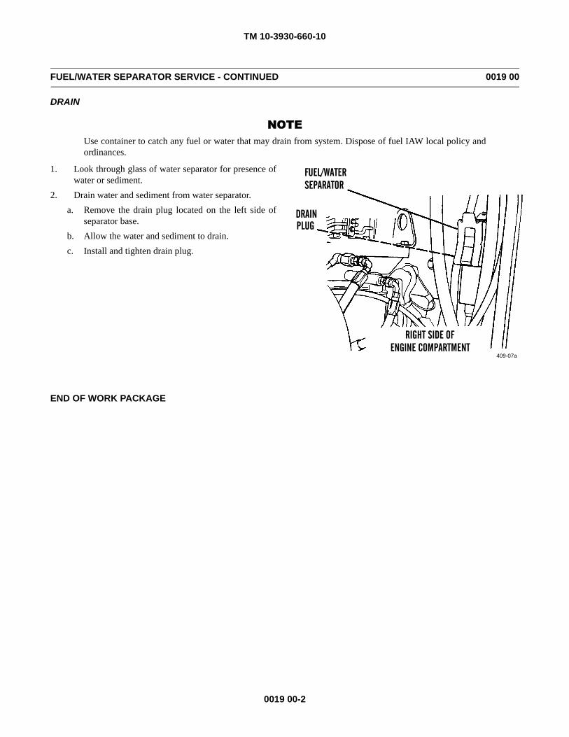
TM 10-3930-660-10
0019 00-2
FUEL/WATER SEPARATOR SERVICE - CONTINUED 0019 00
DRAIN
NOTEUse container to catch any fuel or water that may drain from system. Dispose of fuel IAW local policy andordinances.
1. Look through glass of water separator for presence ofwater or sediment.
2. Drain water and sediment from water separator.a. Remove the drain plug located on the left side of
separator base.b. Allow the water and sediment to drain.c. Install and tighten drain plug.
END OF WORK PACKAGE
409-07a
FUEL/WATERSEPARATOR
DRAIN
RIGHT SIDE OFENGINE COMPARTMENT
PLUG
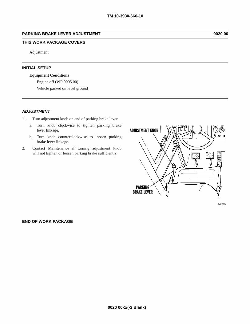
TM 10-3930-660-10
0020 00-1/(-2 Blank)
PARKING BRAKE LEVER ADJUSTMENT 0020 00
THIS WORK PACKAGE COVERS
Adjustment
INITIAL SETUP
Equipment ConditionsEngine off (WP 0005 00)Vehicle parked on level ground
ADJUSTMENT
1. Turn adjustment knob on end of parking brake lever.a. Turn knob clockwise to tighten parking brake
lever linkage.b. Turn knob counterclockwise to loosen parking
brake lever linkage.2. Contact Maintenance if turning adjustment knob
will not tighten or loosen parking brake sufficiently.
END OF WORK PACKAGE
409-071
ADJUSTMENT KNOB
PARKINGBRAKE LEVER

TM 10-3930-660-10
0021 00-1
DRAINING AND FILLING FUEL TANK/HYDRAULIC OIL RESERVOIR 0021 00
THIS WORK PACKAGE COVERS
Drain and Fill Fuel TankDrain and Fill Hydraulic Oil Reservoir
INITIAL SETUP
Materials/PartsFuel (Item 4, 5 or 6, WP 0025 00)Oil, lubricating (Item 8 or 11, WP 0025 00)Rag, wiping (Item 14, WP 0025 00)
Equipment ConditionsEngine off (WP 0005 00)Vehicle parked on level ground
WARNING• DO NOT perform fuel system checks, inspections or maintenance while smoking or near fire, flames or
sparks. Fuel may ignite, causing injury, death or damage to forklift.• Wear fuel-resistant gloves when handling fuels and promptly wash exposed skin and change fuel-
soaked clothing.• Place portable fire extinguisher within reach prior to draining fuel tank.• Fuel is very slippery. To avoid injury, wipe up spilled fuel with rags. Before starting forklift, check that
no fuel is spilled on or around vehicle.
NOTE• Dispose of fuel and oil IAW local policies and ordinances.• Fuel side of fuel/hydraulic oil reservoir contains 44 gal. (166.5 l) of fuel when full.• Hydraulic oil side of fuel/hydraulic oil reservoir contains 56.6 gal. (214.2 L) of oil when full.
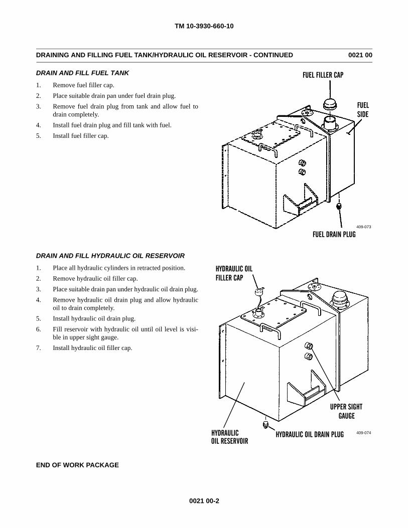
TM 10-3930-660-10
0021 00-2
DRAINING AND FILLING FUEL TANK/HYDRAULIC OIL RESERVOIR - CONTINUED 0021 00
DRAIN AND FILL FUEL TANK
1. Remove fuel filler cap.2. Place suitable drain pan under fuel drain plug.3. Remove fuel drain plug from tank and allow fuel to
drain completely.4. Install fuel drain plug and fill tank with fuel.5. Install fuel filler cap.
DRAIN AND FILL HYDRAULIC OIL RESERVOIR
1. Place all hydraulic cylinders in retracted position.2. Remove hydraulic oil filler cap.3. Place suitable drain pan under hydraulic oil drain plug.4. Remove hydraulic oil drain plug and allow hydraulic
oil to drain completely.5. Install hydraulic oil drain plug.6. Fill reservoir with hydraulic oil until oil level is visi-
ble in upper sight gauge.7. Install hydraulic oil filler cap.
END OF WORK PACKAGE
FUEL FILLER CAP
FUEL DRAIN PLUG
FUELSIDE
409-073
409-074
HYDRAULIC OILFILLER CAP
UPPER SIGHTGAUGE
HYDRAULICOIL RESERVOIR
HYDRAULIC OIL DRAIN PLUG

TM 10-3930-660-10
CHAPTER 5SUPPORTING INFORMATION

TM 10-3930-660-10
0022 00-1/(-2 Blank)
REFERENCES 0022 00
SCOPE
This work package lists all publication indexes, forms, field manuals, technical manuals and other publications refer-enced in this manual and which apply to operation and operator maintenance of the 6000 lb. Variable Reach Rough TerrainForklift Truck.
PUBLICATION INDEXES
The following indexes should be consulted frequently for latest changes or revisions and for new publications relating tomaterial covered in this technical manual.Functional User’s Manual for The Army Maintenance Management System (TAMMS) . . . . . . . . . . . . . . . . DA PAM 738-751
FORMS
Refer to DA PAM 738-751, Functional User’s Manual for The Army Maintenance Management System (TAMMS), forinstructions on the use of maintenance forms.Equipment Inspection and Maintenance Worksheet . . . . . . . . . . . . . . . . . . . . . . . . . . . . . . . . DA Form 2404, DA Form 5988-EProduct Quality Deficiency Report . . . . . . . . . . . . . . . . . . . . . . . . . . . . . . . . . . . . . . . . . . . . . . . . . . . . . . . . . . . . . . SF Form 368Recommended Changes to Publications and Blank Forms. . . . . . . . . . . . . . . . . . . . . . . . . . . . . . . . . . . . . . . . . . DA Form 2028
FIELD MANUALS
Basic Cold Weather Manual . . . . . . . . . . . . . . . . . . . . . . . . . . . . . . . . . . . . . . . . . . . . . . . . . . . . . . . . . . . . . . . . . . . . . .FM 31-70Chemical and Biological Contamination Avoidance . . . . . . . . . . . . . . . . . . . . . . . . . . . . . . . . . . . . . . . . . . . . . . . . . . . . .FM 3-3Desert Operations . . . . . . . . . . . . . . . . . . . . . . . . . . . . . . . . . . . . . . . . . . . . . . . . . . . . . . . . . . . . . . . . . . . . . . . . . . . . . . .FM 90-3First Aid. . . . . . . . . . . . . . . . . . . . . . . . . . . . . . . . . . . . . . . . . . . . . . . . . . . . . . . . . . . . . . . . . . . . . . . . . . . . . . . . . . . . FM 4-25.11Multiservice Tactics, Techniques, and Procedures for Nuclear, Biological, and Chemical (NBC) Protection . . . . . . FM 3-11.4NBC Decontamination . . . . . . . . . . . . . . . . . . . . . . . . . . . . . . . . . . . . . . . . . . . . . . . . . . . . . . . . . . . . . . . . . . . . . . . . . . . .FM 3-5Northern Operations . . . . . . . . . . . . . . . . . . . . . . . . . . . . . . . . . . . . . . . . . . . . . . . . . . . . . . . . . . . . . . . . . . . . . . . . . . . .FM 31-71Nuclear Contamination Avoidance . . . . . . . . . . . . . . . . . . . . . . . . . . . . . . . . . . . . . . . . . . . . . . . . . . . . . . . . . . . . . . . . . FM 3-3-1Operations and Maintenance of Ordnance Materiel in Cold Weather . . . . . . . . . . . . . . . . . . . . . . . . . . . . . . . . . . . . . .FM 9-207
TECHNICAL BULLETINS
Use of Antifreeze Solutions, Antifreeze Extender, Cleaning Compounds . . . . . . . . . . . . . . . . . . . . . . . . . . . . . . . . . TB 750-651Warranty Technical Bulletin . . . . . . . . . . . . . . . . . . . . . . . . . . . . . . . . . . . . . . . . . . . . . . . . . . . . . . . . . . . . . .TB 10-3930-660-14
TECHNICAL MANUALS
Materials Used for Cleaning, Preserving, Abrading and Cementing Ordnance Materiel and Related Materiels Including Chemicals . . . . . . . . . . . . . . . . . . . . . . . . . . . . . . . . . . . . . . . . . . . . . . . . . . . . . . . . . TM 9-247
Operator’s, Unit, Intermediate Direct Support, and Intermediate General SupportMaintenance Manual for Lead-Acid Storage Batteries . . . . . . . . . . . . . . . . . . . . . . . . . . . . . . . . . . . . . . TM 9-6140-200-14
Use of Antifreeze Solutions, Antifreeze Extender, Cleaning Compounds . . . . . . . . . . . . . . . . . . . . . . . . . . . . . . . . . TB 750-651
OTHER PUBLICATIONS
Expendable/Durable Items (Except Medical, Class V, Repair Parts, and Heraldic Items) . . . . . . . . . . . . . . . . . . . . .CTA 50-970
END OF WORK PACKAGE

TM 10-3930-660-10
0023 00-1
BASIC ISSUE ITEMS (BII) LIST 0023 00
SCOPE
This work package lists basic issue items for the 6K forklift to help you inventory items required for safe and efficientoperation. There are no Components of the End Item (COEI) for the 6K forklift.
GENERAL
The BII information is divided into the following lists:Table 1, Basic Issue Items List. These are the minimum essential items required to place the forklift in operation, to
operate it and to perform emergency repairs. Although shipped separately packaged, BII must be with the forklift during oper-ation and whenever it is transferred between property accounts. This manual is your authority to request/requisition replace-ment BII, based on TOE/MTOE authorization of end item. Illustrations are furnished to assist you in identifying the items.
EXPLANATION OF COLUMNS
Below is an explanation of columns found in the tabular listings:1. Column (1) - Illustration Number (Illus Number). This column indicates the number of the illustration that shows the
item.2. Column (2) - National Stock Number. Indicates the National Stock Number (NSN) assigned to the item and will be used
for requisitioning purposes.3. Column (3) - Description, CAGEC, and Part Number. Indicates the Federal item name (in all capital letters) and, if
required, a minimum description in parentheses to identify and locate the item. The entry for each item ends with theCommercial and Government Entity Code (CAGEC) in parentheses followed by the part number.
4. Column (4) - Usable on Code. Indicates a code if the item needed is not the same for different models of equipment. 5. Column (5) - Unit of Measure (U/M). Indicates how the item is issued for the National Stock Number shown in Column
(2).6. Column (6) - Quantity Required (Qty Rqd). Indicates the quantity of the item required.
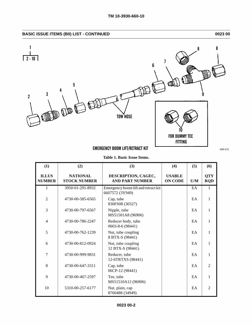
TM 10-3930-660-10
0023 00-2
BASIC ISSUE ITEMS (BII) LIST - CONTINUED 0023 00
Table 1. Basic Issue Items.
(1)
ILLUSNUMBER
(2)
NATIONALSTOCK NUMBER
(3)
DESCRIPTION, CAGEC,AND PART NUMBER
(4)
USABLE ON CODE
(5)
U/M
(6)
QTYRQD
1 3950-01-291-8932 Emergency boom lift and retract kit6607572 (3Y949)
EA 1
2 4730-00-585-6565 Cap, tube830FS08 (30327)
EA 1
3 4730-00-797-6567 Nipple, tubeMS51501A8 (96906)
EA 1
4 4730-00-786-2247 Reducer body, tube0603-8-6 (98441)
EA 1
5 4730-00-762-1239 Nut, tube coupling8 BTX-S (98441)
EA 1
6 4730-00-812-0924 Nut, tube coupling12 BTX-S (98441)
EA 1
7 4730-00-999-9831 Reducer, tube12-6TRTXS (98441)
EA 1
8 4730-00-647-3311 Cap, tube06CP-12 (98441)
EA 2
9 4730-00-467-2597 Tee, tubeMS51510A12 (96906)
EA 1
10 5310-00-257-6177 Nut, plain, cap8760488 (34949)
EA 2
409-075
2 34
5
67
8
9
10FOR DUMMY TEE
FITTING
8
TOW HOSE
2 - 10
1
EMERGENCY BOOM LIFT/RETRACT KIT
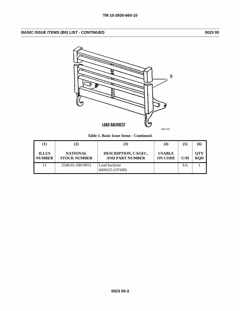
TM 10-3930-660-10
0023 00-3
BASIC ISSUE ITEMS (BII) LIST - CONTINUED 0023 00
Table 1. Basic Issue Items - Continued.
(1)
ILLUSNUMBER
(2)
NATIONALSTOCK NUMBER
(3)
DESCRIPTION, CAGEC,AND PART NUMBER
(4)
USABLE ON CODE
(5)
U/M
(6)
QTYRQD
11 2540-01-289-9053 Load backrest6608325 (3Y949)
EA 1
409-076
11
LOAD BACKREST
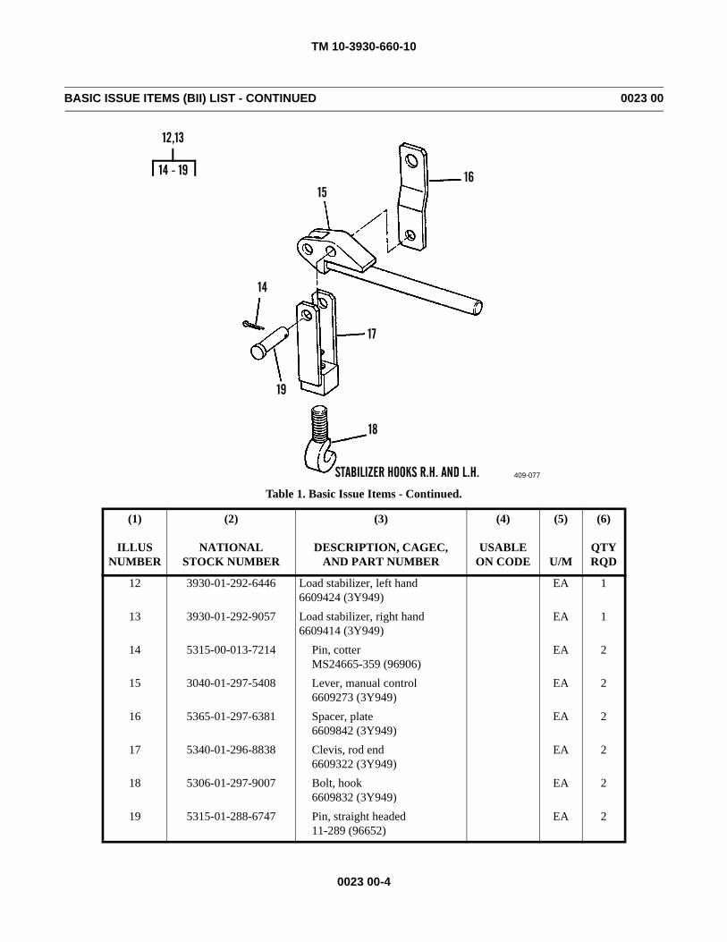
TM 10-3930-660-10
0023 00-4
BASIC ISSUE ITEMS (BII) LIST - CONTINUED 0023 00
Table 1. Basic Issue Items - Continued.
(1)
ILLUSNUMBER
(2)
NATIONALSTOCK NUMBER
(3)
DESCRIPTION, CAGEC,AND PART NUMBER
(4)
USABLE ON CODE
(5)
U/M
(6)
QTYRQD
12 3930-01-292-6446 Load stabilizer, left hand6609424 (3Y949)
EA 1
13 3930-01-292-9057 Load stabilizer, right hand6609414 (3Y949)
EA 1
14 5315-00-013-7214 Pin, cotterMS24665-359 (96906)
EA 2
15 3040-01-297-5408 Lever, manual control6609273 (3Y949)
EA 2
16 5365-01-297-6381 Spacer, plate6609842 (3Y949)
EA 2
17 5340-01-296-8838 Clevis, rod end6609322 (3Y949)
EA 2
18 5306-01-297-9007 Bolt, hook6609832 (3Y949)
EA 2
19 5315-01-288-6747 Pin, straight headed11-289 (96652)
EA 2
409-077
1516
17
18
19
14
14 - 19
12,13
STABILIZER HOOKS R.H. AND L.H.
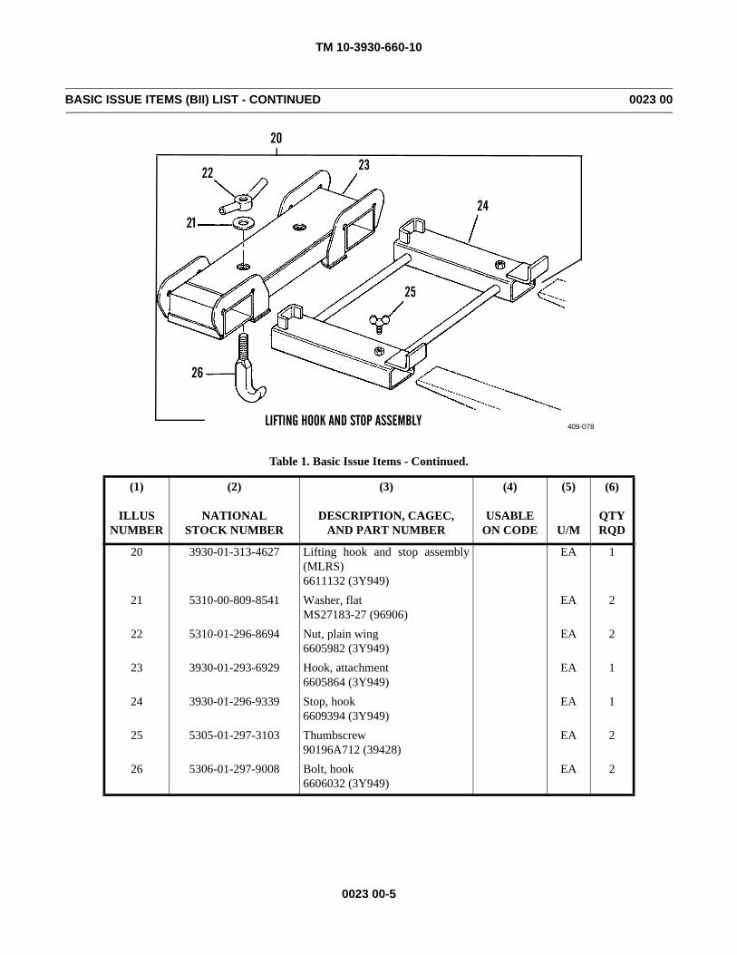
TM 10-3930-660-10
0023 00-5
BASIC ISSUE ITEMS (BII) LIST - CONTINUED 0023 00
Table 1. Basic Issue Items - Continued.
(1)
ILLUSNUMBER
(2)
NATIONALSTOCK NUMBER
(3)
DESCRIPTION, CAGEC,AND PART NUMBER
(4)
USABLE ON CODE
(5)
U/M
(6)
QTYRQD
20 3930-01-313-4627 Lifting hook and stop assembly(MLRS)6611132 (3Y949)
EA 1
21 5310-00-809-8541 Washer, flatMS27183-27 (96906)
EA 2
22 5310-01-296-8694 Nut, plain wing6605982 (3Y949)
EA 2
23 3930-01-293-6929 Hook, attachment6605864 (3Y949)
EA 1
24 3930-01-296-9339 Stop, hook6609394 (3Y949)
EA 1
25 5305-01-297-3103 Thumbscrew90196A712 (39428)
EA 2
26 5306-01-297-9008 Bolt, hook6606032 (3Y949)
EA 2
409-078
21
22 23
24
25
20
26
LIFTING HOOK AND STOP ASSEMBLY
TM 10-3930-660-10
0023 00-6
BASIC ISSUE ITEMS (BII) LISTS - CONTINUED 0023 00
Table 1. Basic Issue Items - Continued.
END OF WORK PACKAGE
(1)
ILLUSNUMBER
(2)
NATIONALSTOCK NUMBER
(3)
DESCRIPTION, CAGEC,AND PART NUMBER
(4)
USABLE ON CODE
(5)
U/M
(6)
QTYRQD
27 TM10-3930-660-10 Operator’s Manual
409-079
27
TM 10-3930-660-10
0024 00-1/(-2 Blank)
ADDITIONAL AUTHORIZATION LIST (AAL) 0024 00
SCOPE
This work package lists additional items you are authorized for support of the 6K forklift.
GENERAL
This list identifies items that do not have to accompany the 6K forklift and that do not have to be turned in with it. Theseitems are all authorized to you by CTA, MTOE, TDA or JTA.
EXPLANATION OF COLUMNS
1. Column (1) - National Stock Number. Indicates the National Stock Number (NSN) assigned to the item and will be usedfor requisitioning purposes.
2. Column (2) - Description, CAGEC, and Part Number. Indicates the Federal item name (in all capital letters) followedby a minimum description when needed. The entry for each item ends with the Commercial and Government Entity Code(CAGEC) in parentheses followed by the part number.
3. Column (3) - Usable on Code. Indicates a code if the item needed is not the same for different models of equipment. 4. Column (4) - Unit of Measure (U/M). Indicates how the item is issued for the National Stock Number shown in Column
(1).5. Column (5) - Qty Auth. Indicates the quantity authorized.
END OF WORK PACKAGE
Table 1. Additional Authorization List
(1)
NATIONALSTOCK NUMBER
(2)
DESCRIPTION, CAGEC,AND PART NUMBER
(3)
USABLE ON CODE
(4)
U/M
(5)
QTYAUTH
4210-01-493-8162 Fire extinguisher, 5 lb (98752)B500T (54905)
EA 1

TM 10-3930-660-10
0025 00-1
EXPENDABLE AND DURABLE ITEMS LIST 0025 00
SCOPE
This work package lists the expendable and durable items you will need to operate and maintain the 6K forklift. Thislisting is for informational purposes only and is not authority to requisition the listed items. These items are authorized to youby CTA 50-970, Expendable/Durable Items (Except Medical, Class V Repair Parts, and Heraldic Items), or CTA 8-100, ArmyMedical Department Expendable/Durable Items.
EXPLANATION OF COLUMNS
1. Column (1) - Item Number. This number is assigned to the entry in the list and is referenced in the narrative instruc-tions to identify the item [e.g., Use antifreeze (Item 1, WP 0025 00)].
2. Column (2) - Level. This column identifies the lowest level of maintenance that requires the listed item.C - Operate/Crew
3. Column (3) - National Stock Number (NSN). This is the NSN assigned to the item which you can use to requisition it.4. Column (4) - Description, Item Name, CAGEC, and Part Number. This provides the other information you need to
identify the item.5. Column (5) - Unit of Measure (U/M). This code shows the physical measurement or count of an item, such as gallon,
dozen, gross, etc.
TM 10-3930-660-10
0025 00-2
EXPENDABLE AND DURABLE ITEMS LIST - CONTINUED 0025 00
Table 1. Expendable and Durable Items List.
(1)
ITEMNUMBER
(2)
LEVEL
(3)
NATIONALSTOCK NUMBER
(4)
DESCRIPTION, CAGEC,AND PART NUMBER
(5)
U/M
1 C ANTIFREEZE: Permanent Ethylene Glycol,Inhibited, Heavy-Duty
6850-01-464-9125 (58536) A-A-526241 Gallon Can GAL
6850-00-181-7933 (81349) MILA461535 Gallon Container GAL
6850-01-441-3223 (58536) A-A-5262455 Gallon Drum GAL
2 C CLEANING COMPOUND: Solvent, Type III(81349) MIL-PRF-680
6850-01-474-23206850-01-474-2321
5 Gallon Can55 Gallon Drum
GALGAL
3 C DETERGENT: General Purpose, Liquid(83421) 7930-00-282-9699
7930-00-282-9699 1 Gallon Can GAL
4 C DIESEL FUEL: DF-1 Grade, Arctic(81346) ASTM D 975
9140-00-286-5286 Bulk GAL
9140-00-286-5287 5 Gallon Can GAL
9140-00-286-5288 55 Gallon Drum GAL
5 C DIESEL FUEL: DF-2 Grade(81346) ASTM D 975
9140-00-286-5294 Bulk GAL
9140-00-286-5295 5 Gallon Can GAL
9140-00-286-5296 55 Gallon Drum GAL
6 C 9130-01-031-5816 FUEL, TURBINE: Aviation (81349) MILT83133 GR JP8
GAL
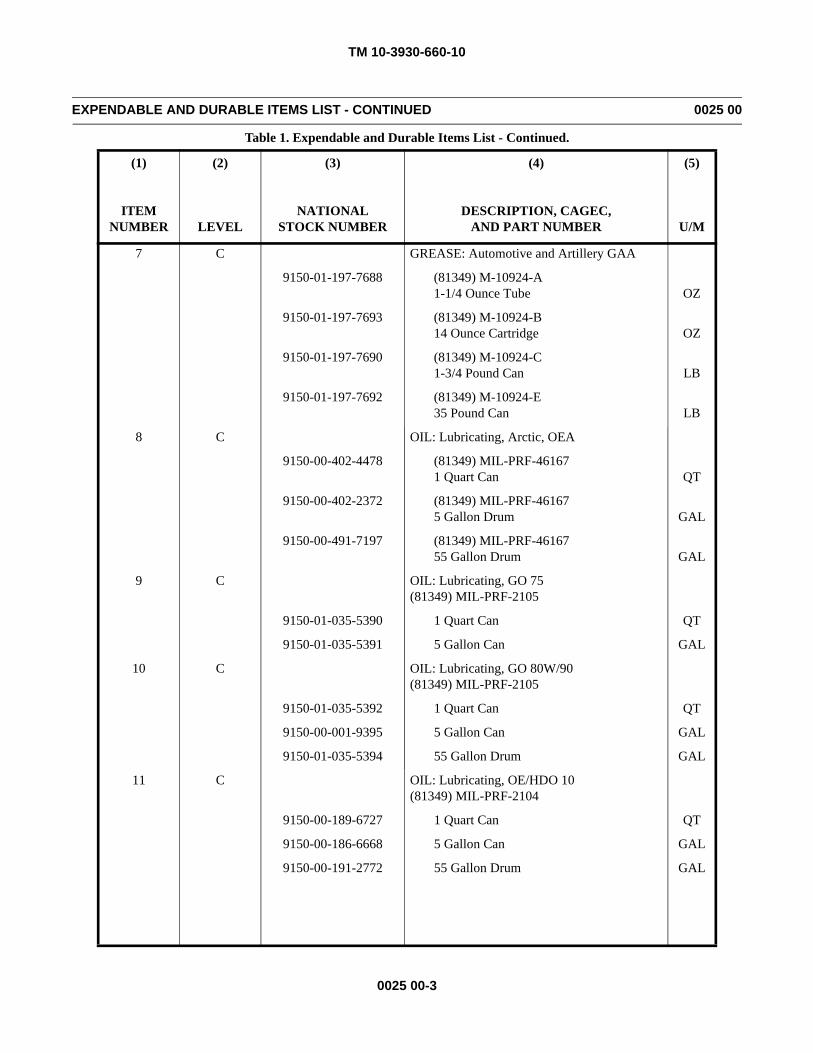
TM 10-3930-660-10
0025 00-3
EXPENDABLE AND DURABLE ITEMS LIST - CONTINUED 0025 00
Table 1. Expendable and Durable Items List - Continued.
(1)
ITEMNUMBER
(2)
LEVEL
(3)
NATIONALSTOCK NUMBER
(4)
DESCRIPTION, CAGEC,AND PART NUMBER
(5)
U/M
7 C GREASE: Automotive and Artillery GAA
9150-01-197-7688 (81349) M-10924-A1-1/4 Ounce Tube OZ
9150-01-197-7693 (81349) M-10924-B14 Ounce Cartridge OZ
9150-01-197-7690 (81349) M-10924-C1-3/4 Pound Can LB
9150-01-197-7692 (81349) M-10924-E35 Pound Can LB
8 C OIL: Lubricating, Arctic, OEA
9150-00-402-4478 (81349) MIL-PRF-461671 Quart Can QT
9150-00-402-2372 (81349) MIL-PRF-461675 Gallon Drum GAL
9150-00-491-7197 (81349) MIL-PRF-4616755 Gallon Drum GAL
9 C OIL: Lubricating, GO 75(81349) MIL-PRF-2105
9150-01-035-5390 1 Quart Can QT
9150-01-035-5391 5 Gallon Can GAL
10 C OIL: Lubricating, GO 80W/90(81349) MIL-PRF-2105
9150-01-035-5392 1 Quart Can QT
9150-00-001-9395 5 Gallon Can GAL
9150-01-035-5394 55 Gallon Drum GAL
11 C OIL: Lubricating, OE/HDO 10(81349) MIL-PRF-2104
9150-00-189-6727 1 Quart Can QT
9150-00-186-6668 5 Gallon Can GAL
9150-00-191-2772 55 Gallon Drum GAL
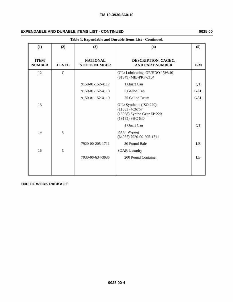
TM 10-3930-660-10
0025 00-4
EXPENDABLE AND DURABLE ITEMS LIST - CONTINUED 0025 00
Table 1. Expendable and Durable Items List - Continued.
END OF WORK PACKAGE
(1)
ITEMNUMBER
(2)
LEVEL
(3)
NATIONALSTOCK NUMBER
(4)
DESCRIPTION, CAGEC,AND PART NUMBER
(5)
U/M
12 C OIL: Lubricating, OE/HDO 15W/40(81349) MIL-PRF-2104
9150-01-152-4117 1 Quart Can QT
9150-01-152-4118 5 Gallon Can GAL
9150-01-152-4119 55 Gallon Drum GAL
13 OIL: Synthetic (ISO 220)(11083) 4C6767(15958) Syntho Gear EP 220(19135) SHC 630
1 Quart Can QT
14 C RAG: Wiping(64067) 7920-00-205-1711
7920-00-205-1711 50 Pound Bale LB
15 C SOAP: Laundry
7930-00-634-3935 200 Pound Container LB
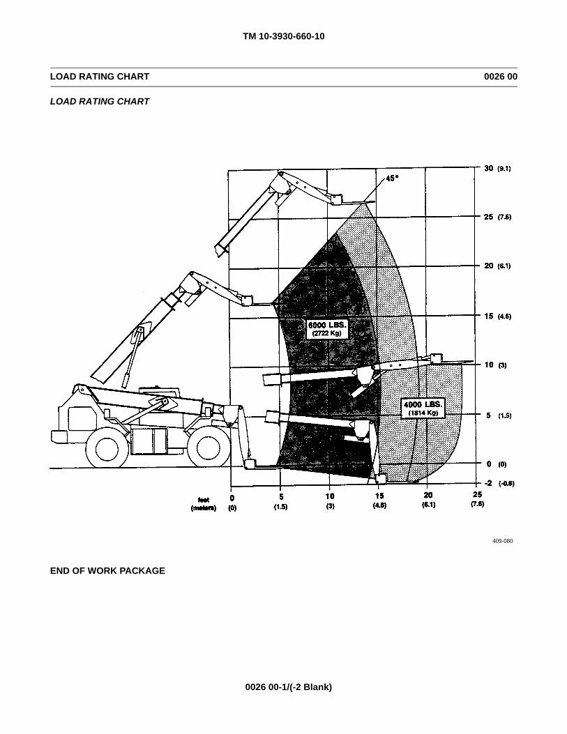
TM 10-3930-660-10
0026 00-1/(-2 Blank)
LOAD RATING CHART 0026 00
LOAD RATING CHART
END OF WORK PACKAGE
409-080

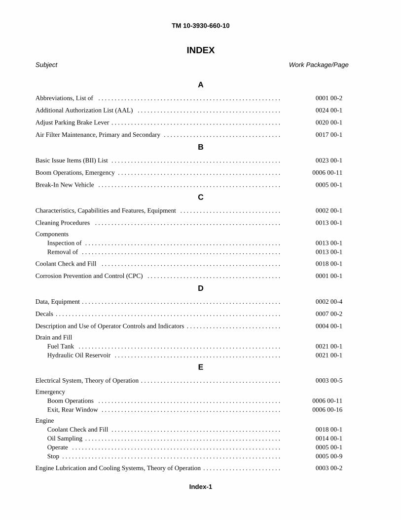
TM 10-3930-660-10
Index-1
INDEXSubject Work Package/Page
AAbbreviations, List of . . . . . . . . . . . . . . . . . . . . . . . . . . . . . . . . . . . . . . . . . . . . . . . . . . . . . . . . 0001 00-2
Additional Authorization List (AAL) . . . . . . . . . . . . . . . . . . . . . . . . . . . . . . . . . . . . . . . . . . . . 0024 00-1
Adjust Parking Brake Lever . . . . . . . . . . . . . . . . . . . . . . . . . . . . . . . . . . . . . . . . . . . . . . . . . . . . 0020 00-1
Air Filter Maintenance, Primary and Secondary . . . . . . . . . . . . . . . . . . . . . . . . . . . . . . . . . . . . 0017 00-1
BBasic Issue Items (BII) List . . . . . . . . . . . . . . . . . . . . . . . . . . . . . . . . . . . . . . . . . . . . . . . . . . . . 0023 00-1
Boom Operations, Emergency . . . . . . . . . . . . . . . . . . . . . . . . . . . . . . . . . . . . . . . . . . . . . . . . . . 0006 00-11
Break-In New Vehicle . . . . . . . . . . . . . . . . . . . . . . . . . . . . . . . . . . . . . . . . . . . . . . . . . . . . . . . . 0005 00-1
CCharacteristics, Capabilities and Features, Equipment . . . . . . . . . . . . . . . . . . . . . . . . . . . . . . . 0002 00-1
Cleaning Procedures . . . . . . . . . . . . . . . . . . . . . . . . . . . . . . . . . . . . . . . . . . . . . . . . . . . . . . . . . 0013 00-1
ComponentsInspection of . . . . . . . . . . . . . . . . . . . . . . . . . . . . . . . . . . . . . . . . . . . . . . . . . . . . . . . . . . . . 0013 00-1Removal of . . . . . . . . . . . . . . . . . . . . . . . . . . . . . . . . . . . . . . . . . . . . . . . . . . . . . . . . . . . . . 0013 00-1
Coolant Check and Fill . . . . . . . . . . . . . . . . . . . . . . . . . . . . . . . . . . . . . . . . . . . . . . . . . . . . . . . 0018 00-1
Corrosion Prevention and Control (CPC) . . . . . . . . . . . . . . . . . . . . . . . . . . . . . . . . . . . . . . . . . 0001 00-1
DData, Equipment . . . . . . . . . . . . . . . . . . . . . . . . . . . . . . . . . . . . . . . . . . . . . . . . . . . . . . . . . . . . . 0002 00-4
Decals . . . . . . . . . . . . . . . . . . . . . . . . . . . . . . . . . . . . . . . . . . . . . . . . . . . . . . . . . . . . . . . . . . . . . 0007 00-2
Description and Use of Operator Controls and Indicators . . . . . . . . . . . . . . . . . . . . . . . . . . . . . 0004 00-1
Drain and FillFuel Tank . . . . . . . . . . . . . . . . . . . . . . . . . . . . . . . . . . . . . . . . . . . . . . . . . . . . . . . . . . . . . . 0021 00-1Hydraulic Oil Reservoir . . . . . . . . . . . . . . . . . . . . . . . . . . . . . . . . . . . . . . . . . . . . . . . . . . . 0021 00-1
EElectrical System, Theory of Operation . . . . . . . . . . . . . . . . . . . . . . . . . . . . . . . . . . . . . . . . . . . 0003 00-5
EmergencyBoom Operations . . . . . . . . . . . . . . . . . . . . . . . . . . . . . . . . . . . . . . . . . . . . . . . . . . . . . . . . 0006 00-11Exit, Rear Window . . . . . . . . . . . . . . . . . . . . . . . . . . . . . . . . . . . . . . . . . . . . . . . . . . . . . . . 0006 00-16
EngineCoolant Check and Fill . . . . . . . . . . . . . . . . . . . . . . . . . . . . . . . . . . . . . . . . . . . . . . . . . . . . 0018 00-1Oil Sampling . . . . . . . . . . . . . . . . . . . . . . . . . . . . . . . . . . . . . . . . . . . . . . . . . . . . . . . . . . . . 0014 00-1Operate . . . . . . . . . . . . . . . . . . . . . . . . . . . . . . . . . . . . . . . . . . . . . . . . . . . . . . . . . . . . . . . . 0005 00-1Stop . . . . . . . . . . . . . . . . . . . . . . . . . . . . . . . . . . . . . . . . . . . . . . . . . . . . . . . . . . . . . . . . . . . 0005 00-9
Engine Lubrication and Cooling Systems, Theory of Operation . . . . . . . . . . . . . . . . . . . . . . . . 0003 00-2
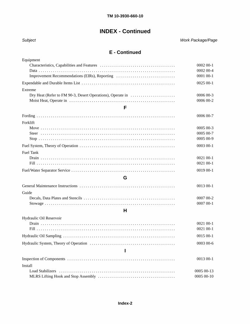
TM 10-3930-660-10
Index-2
INDEX - ContinuedSubject Work Package/Page
E - ContinuedEquipment
Characteristics, Capabilities and Features . . . . . . . . . . . . . . . . . . . . . . . . . . . . . . . . . . . . . 0002 00-1Data . . . . . . . . . . . . . . . . . . . . . . . . . . . . . . . . . . . . . . . . . . . . . . . . . . . . . . . . . . . . . . . . . . . 0002 00-4Improvement Recommendations (EIRs), Reporting . . . . . . . . . . . . . . . . . . . . . . . . . . . . . 0001 00-1
Expendable and Durable Items List . . . . . . . . . . . . . . . . . . . . . . . . . . . . . . . . . . . . . . . . . . . . . . 0025 00-1
ExtremeDry Heat (Refer to FM 90-3, Desert Operations), Operate in . . . . . . . . . . . . . . . . . . . . . . 0006 00-3Moist Heat, Operate in . . . . . . . . . . . . . . . . . . . . . . . . . . . . . . . . . . . . . . . . . . . . . . . . . . . . 0006 00-2
FFording . . . . . . . . . . . . . . . . . . . . . . . . . . . . . . . . . . . . . . . . . . . . . . . . . . . . . . . . . . . . . . . . . . . . 0006 00-7
ForkliftMove . . . . . . . . . . . . . . . . . . . . . . . . . . . . . . . . . . . . . . . . . . . . . . . . . . . . . . . . . . . . . . . . . . 0005 00-3Steer . . . . . . . . . . . . . . . . . . . . . . . . . . . . . . . . . . . . . . . . . . . . . . . . . . . . . . . . . . . . . . . . . . 0005 00-7Stop . . . . . . . . . . . . . . . . . . . . . . . . . . . . . . . . . . . . . . . . . . . . . . . . . . . . . . . . . . . . . . . . . . . 0005 00-9
Fuel System, Theory of Operation . . . . . . . . . . . . . . . . . . . . . . . . . . . . . . . . . . . . . . . . . . . . . . . 0003 00-1
Fuel TankDrain . . . . . . . . . . . . . . . . . . . . . . . . . . . . . . . . . . . . . . . . . . . . . . . . . . . . . . . . . . . . . . . . . . 0021 00-1Fill . . . . . . . . . . . . . . . . . . . . . . . . . . . . . . . . . . . . . . . . . . . . . . . . . . . . . . . . . . . . . . . . . . . . 0021 00-1
Fuel/Water Separator Service . . . . . . . . . . . . . . . . . . . . . . . . . . . . . . . . . . . . . . . . . . . . . . . . . . . 0019 00-1
GGeneral Maintenance Instructions . . . . . . . . . . . . . . . . . . . . . . . . . . . . . . . . . . . . . . . . . . . . . . . 0013 00-1
GuideDecals, Data Plates and Stencils . . . . . . . . . . . . . . . . . . . . . . . . . . . . . . . . . . . . . . . . . . . . . 0007 00-2Stowage . . . . . . . . . . . . . . . . . . . . . . . . . . . . . . . . . . . . . . . . . . . . . . . . . . . . . . . . . . . . . . . . 0007 00-1
HHydraulic Oil Reservoir
Drain . . . . . . . . . . . . . . . . . . . . . . . . . . . . . . . . . . . . . . . . . . . . . . . . . . . . . . . . . . . . . . . . . . 0021 00-1Fill . . . . . . . . . . . . . . . . . . . . . . . . . . . . . . . . . . . . . . . . . . . . . . . . . . . . . . . . . . . . . . . . . . . . 0021 00-1
Hydraulic Oil Sampling . . . . . . . . . . . . . . . . . . . . . . . . . . . . . . . . . . . . . . . . . . . . . . . . . . . . . . . 0015 00-1
Hydraulic System, Theory of Operation . . . . . . . . . . . . . . . . . . . . . . . . . . . . . . . . . . . . . . . . . . 0003 00-6
IInspection of Components . . . . . . . . . . . . . . . . . . . . . . . . . . . . . . . . . . . . . . . . . . . . . . . . . . . . . 0013 00-1
InstallLoad Stabilizers . . . . . . . . . . . . . . . . . . . . . . . . . . . . . . . . . . . . . . . . . . . . . . . . . . . . . . . . . 0005 00-13MLRS Lifting Hook and Stop Assembly . . . . . . . . . . . . . . . . . . . . . . . . . . . . . . . . . . . . . . 0005 00-10
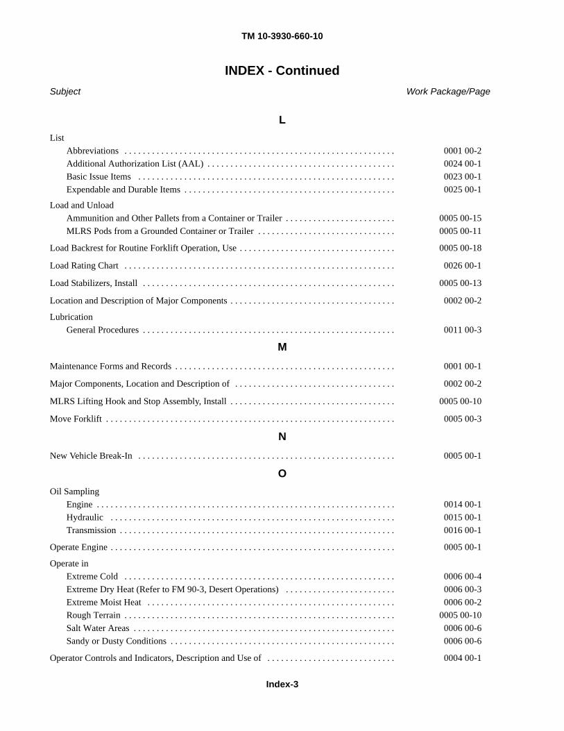
TM 10-3930-660-10
Index-3
INDEX - ContinuedSubject Work Package/Page
LList
Abbreviations . . . . . . . . . . . . . . . . . . . . . . . . . . . . . . . . . . . . . . . . . . . . . . . . . . . . . . . . . . . 0001 00-2Additional Authorization List (AAL) . . . . . . . . . . . . . . . . . . . . . . . . . . . . . . . . . . . . . . . . . 0024 00-1Basic Issue Items . . . . . . . . . . . . . . . . . . . . . . . . . . . . . . . . . . . . . . . . . . . . . . . . . . . . . . . . 0023 00-1Expendable and Durable Items . . . . . . . . . . . . . . . . . . . . . . . . . . . . . . . . . . . . . . . . . . . . . . 0025 00-1
Load and UnloadAmmunition and Other Pallets from a Container or Trailer . . . . . . . . . . . . . . . . . . . . . . . . 0005 00-15MLRS Pods from a Grounded Container or Trailer . . . . . . . . . . . . . . . . . . . . . . . . . . . . . . 0005 00-11
Load Backrest for Routine Forklift Operation, Use . . . . . . . . . . . . . . . . . . . . . . . . . . . . . . . . . . 0005 00-18
Load Rating Chart . . . . . . . . . . . . . . . . . . . . . . . . . . . . . . . . . . . . . . . . . . . . . . . . . . . . . . . . . . . 0026 00-1
Load Stabilizers, Install . . . . . . . . . . . . . . . . . . . . . . . . . . . . . . . . . . . . . . . . . . . . . . . . . . . . . . . 0005 00-13
Location and Description of Major Components . . . . . . . . . . . . . . . . . . . . . . . . . . . . . . . . . . . . 0002 00-2
LubricationGeneral Procedures . . . . . . . . . . . . . . . . . . . . . . . . . . . . . . . . . . . . . . . . . . . . . . . . . . . . . . . 0011 00-3
MMaintenance Forms and Records . . . . . . . . . . . . . . . . . . . . . . . . . . . . . . . . . . . . . . . . . . . . . . . . 0001 00-1
Major Components, Location and Description of . . . . . . . . . . . . . . . . . . . . . . . . . . . . . . . . . . . 0002 00-2
MLRS Lifting Hook and Stop Assembly, Install . . . . . . . . . . . . . . . . . . . . . . . . . . . . . . . . . . . . 0005 00-10
Move Forklift . . . . . . . . . . . . . . . . . . . . . . . . . . . . . . . . . . . . . . . . . . . . . . . . . . . . . . . . . . . . . . . 0005 00-3
NNew Vehicle Break-In . . . . . . . . . . . . . . . . . . . . . . . . . . . . . . . . . . . . . . . . . . . . . . . . . . . . . . . . 0005 00-1
OOil Sampling
Engine . . . . . . . . . . . . . . . . . . . . . . . . . . . . . . . . . . . . . . . . . . . . . . . . . . . . . . . . . . . . . . . . . 0014 00-1Hydraulic . . . . . . . . . . . . . . . . . . . . . . . . . . . . . . . . . . . . . . . . . . . . . . . . . . . . . . . . . . . . . . 0015 00-1Transmission . . . . . . . . . . . . . . . . . . . . . . . . . . . . . . . . . . . . . . . . . . . . . . . . . . . . . . . . . . . . 0016 00-1
Operate Engine . . . . . . . . . . . . . . . . . . . . . . . . . . . . . . . . . . . . . . . . . . . . . . . . . . . . . . . . . . . . . . 0005 00-1
Operate inExtreme Cold . . . . . . . . . . . . . . . . . . . . . . . . . . . . . . . . . . . . . . . . . . . . . . . . . . . . . . . . . . . 0006 00-4Extreme Dry Heat (Refer to FM 90-3, Desert Operations) . . . . . . . . . . . . . . . . . . . . . . . . 0006 00-3Extreme Moist Heat . . . . . . . . . . . . . . . . . . . . . . . . . . . . . . . . . . . . . . . . . . . . . . . . . . . . . . 0006 00-2Rough Terrain . . . . . . . . . . . . . . . . . . . . . . . . . . . . . . . . . . . . . . . . . . . . . . . . . . . . . . . . . . . 0005 00-10Salt Water Areas . . . . . . . . . . . . . . . . . . . . . . . . . . . . . . . . . . . . . . . . . . . . . . . . . . . . . . . . . 0006 00-6Sandy or Dusty Conditions . . . . . . . . . . . . . . . . . . . . . . . . . . . . . . . . . . . . . . . . . . . . . . . . . 0006 00-6
Operator Controls and Indicators, Description and Use of . . . . . . . . . . . . . . . . . . . . . . . . . . . . 0004 00-1
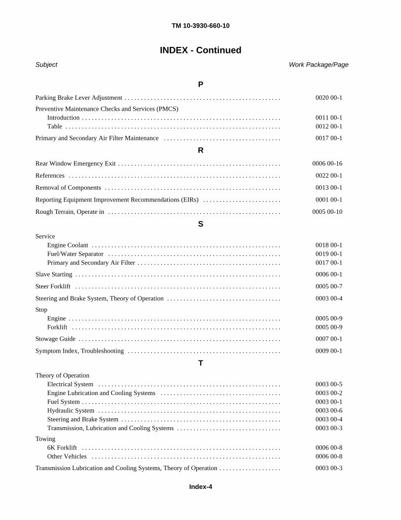
TM 10-3930-660-10
Index-4
INDEX - ContinuedSubject Work Package/Page
PParking Brake Lever Adjustment . . . . . . . . . . . . . . . . . . . . . . . . . . . . . . . . . . . . . . . . . . . . . . . . 0020 00-1
Preventive Maintenance Checks and Services (PMCS)Introduction . . . . . . . . . . . . . . . . . . . . . . . . . . . . . . . . . . . . . . . . . . . . . . . . . . . . . . . . . . . . . 0011 00-1Table . . . . . . . . . . . . . . . . . . . . . . . . . . . . . . . . . . . . . . . . . . . . . . . . . . . . . . . . . . . . . . . . . . 0012 00-1
Primary and Secondary Air Filter Maintenance . . . . . . . . . . . . . . . . . . . . . . . . . . . . . . . . . . . . 0017 00-1
RRear Window Emergency Exit . . . . . . . . . . . . . . . . . . . . . . . . . . . . . . . . . . . . . . . . . . . . . . . . . . 0006 00-16
References . . . . . . . . . . . . . . . . . . . . . . . . . . . . . . . . . . . . . . . . . . . . . . . . . . . . . . . . . . . . . . . . . 0022 00-1
Removal of Components . . . . . . . . . . . . . . . . . . . . . . . . . . . . . . . . . . . . . . . . . . . . . . . . . . . . . . 0013 00-1
Reporting Equipment Improvement Recommendations (EIRs) . . . . . . . . . . . . . . . . . . . . . . . . 0001 00-1
Rough Terrain, Operate in . . . . . . . . . . . . . . . . . . . . . . . . . . . . . . . . . . . . . . . . . . . . . . . . . . . . . 0005 00-10
SService
Engine Coolant . . . . . . . . . . . . . . . . . . . . . . . . . . . . . . . . . . . . . . . . . . . . . . . . . . . . . . . . . . 0018 00-1Fuel/Water Separator . . . . . . . . . . . . . . . . . . . . . . . . . . . . . . . . . . . . . . . . . . . . . . . . . . . . . 0019 00-1Primary and Secondary Air Filter . . . . . . . . . . . . . . . . . . . . . . . . . . . . . . . . . . . . . . . . . . . . 0017 00-1
Slave Starting . . . . . . . . . . . . . . . . . . . . . . . . . . . . . . . . . . . . . . . . . . . . . . . . . . . . . . . . . . . . . . . 0006 00-1
Steer Forklift . . . . . . . . . . . . . . . . . . . . . . . . . . . . . . . . . . . . . . . . . . . . . . . . . . . . . . . . . . . . . . . 0005 00-7
Steering and Brake System, Theory of Operation . . . . . . . . . . . . . . . . . . . . . . . . . . . . . . . . . . . 0003 00-4
StopEngine . . . . . . . . . . . . . . . . . . . . . . . . . . . . . . . . . . . . . . . . . . . . . . . . . . . . . . . . . . . . . . . . . 0005 00-9Forklift . . . . . . . . . . . . . . . . . . . . . . . . . . . . . . . . . . . . . . . . . . . . . . . . . . . . . . . . . . . . . . . . 0005 00-9
Stowage Guide . . . . . . . . . . . . . . . . . . . . . . . . . . . . . . . . . . . . . . . . . . . . . . . . . . . . . . . . . . . . . . 0007 00-1
Symptom Index, Troubleshooting . . . . . . . . . . . . . . . . . . . . . . . . . . . . . . . . . . . . . . . . . . . . . . . 0009 00-1
TTheory of Operation
Electrical System . . . . . . . . . . . . . . . . . . . . . . . . . . . . . . . . . . . . . . . . . . . . . . . . . . . . . . . . 0003 00-5Engine Lubrication and Cooling Systems . . . . . . . . . . . . . . . . . . . . . . . . . . . . . . . . . . . . . 0003 00-2Fuel System . . . . . . . . . . . . . . . . . . . . . . . . . . . . . . . . . . . . . . . . . . . . . . . . . . . . . . . . . . . . . 0003 00-1Hydraulic System . . . . . . . . . . . . . . . . . . . . . . . . . . . . . . . . . . . . . . . . . . . . . . . . . . . . . . . . 0003 00-6Steering and Brake System . . . . . . . . . . . . . . . . . . . . . . . . . . . . . . . . . . . . . . . . . . . . . . . . . 0003 00-4Transmission, Lubrication and Cooling Systems . . . . . . . . . . . . . . . . . . . . . . . . . . . . . . . . 0003 00-3
Towing6K Forklift . . . . . . . . . . . . . . . . . . . . . . . . . . . . . . . . . . . . . . . . . . . . . . . . . . . . . . . . . . . . . 0006 00-8Other Vehicles . . . . . . . . . . . . . . . . . . . . . . . . . . . . . . . . . . . . . . . . . . . . . . . . . . . . . . . . . . 0006 00-8
Transmission Lubrication and Cooling Systems, Theory of Operation . . . . . . . . . . . . . . . . . . . 0003 00-3
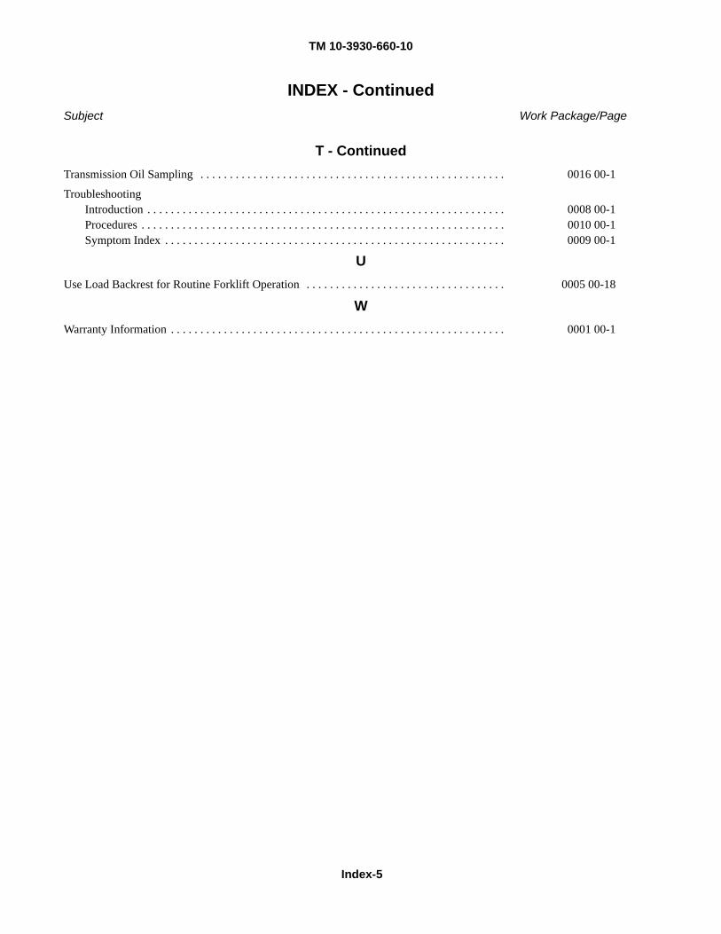
TM 10-3930-660-10
Index-5
INDEX - ContinuedSubject Work Package/Page
T - ContinuedTransmission Oil Sampling . . . . . . . . . . . . . . . . . . . . . . . . . . . . . . . . . . . . . . . . . . . . . . . . . . . . 0016 00-1
TroubleshootingIntroduction . . . . . . . . . . . . . . . . . . . . . . . . . . . . . . . . . . . . . . . . . . . . . . . . . . . . . . . . . . . . . 0008 00-1Procedures . . . . . . . . . . . . . . . . . . . . . . . . . . . . . . . . . . . . . . . . . . . . . . . . . . . . . . . . . . . . . . 0010 00-1Symptom Index . . . . . . . . . . . . . . . . . . . . . . . . . . . . . . . . . . . . . . . . . . . . . . . . . . . . . . . . . . 0009 00-1
UUse Load Backrest for Routine Forklift Operation . . . . . . . . . . . . . . . . . . . . . . . . . . . . . . . . . . 0005 00-18
WWarranty Information . . . . . . . . . . . . . . . . . . . . . . . . . . . . . . . . . . . . . . . . . . . . . . . . . . . . . . . . . 0001 00-1
Distribution: To be distributed in accordance with the initial distribution number (IDN) 254834, requirements for TM 10-3930-660-10.
By Order of the Secretary of the Army:
PETER J. SCHOOMAKER General, United States Army
Chief of Staff Official:
JOYCE E. MORROW Administrative Assistant to the
Secretary of the Army0609310
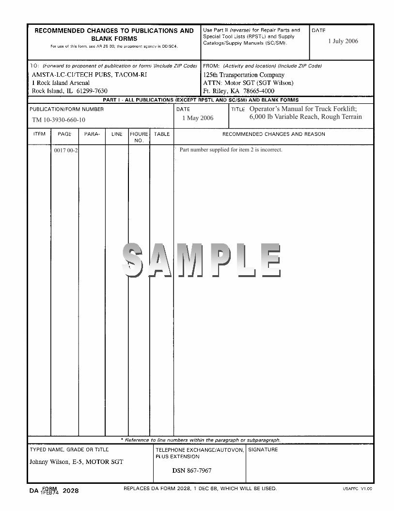
1 May 2006
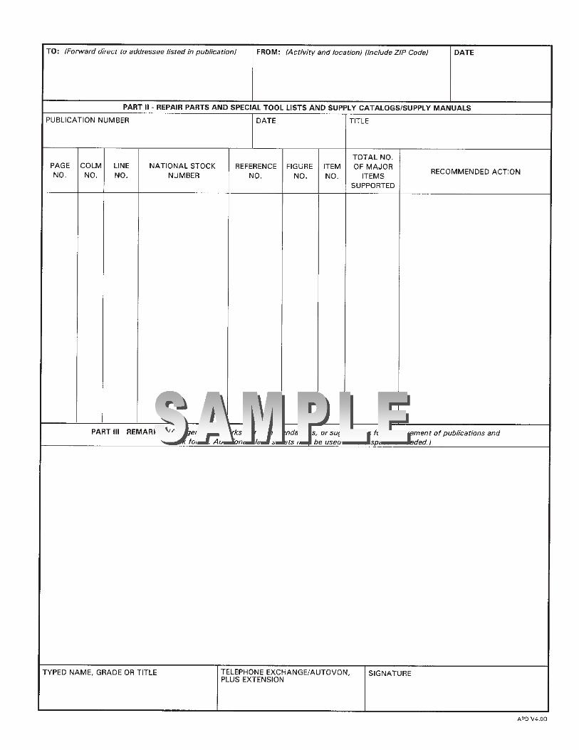
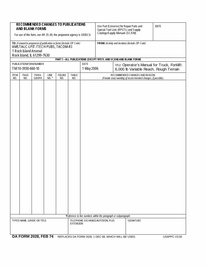
RECOMMENDED CHANGES TO PUBLICATIONS AND BLANK FORMS
For use of this form, see AR 25-30; the proponent agency is ODISC4.
Use Part II (reverse) for Repair Parts and Special Tool Lists (RPSTL) and Supply Catalogs/Supply Manuals (SC/SM).
DATE
TO: (Forward to proponent of publication or form) (Include ZIP Code) AMSTA-LC-LPIT / TECH PUBS, TACOM-RI 1 Rock Island Arsenal Rock Island, IL 61299-7630
FROM: (Activity and location) (Include ZIP Code)
PART I – ALL PUBLICATIONS (EXCEPT RPSTL AND SC/SM) AND BLANK FORMS
PUBLICATION/FORM NUMBER
TM 10-3930-660-10 DATE
1 May 2006 TITLE Operator’s Manual for Truck, Forklift: 6,000 lb Variable Reach, Rough Terrain
ITEM NO.
PAGE NO.
PARA- GRAPH
LINE NO. *
FIGURE NO.
TABLE NO.
RECOMMENDED CHANGES AND REASON (Provide exact wording of recom mended changes, if possible).
*Reference to line numbers within the paragraph or subparagraph.
TYPED NAME, GRADE OR TITLE
TELEPHONE EXCHANGE/AUTOVON, PLUS EXTENSION
SIGNATURE
DA FORM 2028, FEB 74 REPLACES DA FORM 2028, 1 DEC 68, WHICH WILL BE USED. USAPPC V3.00

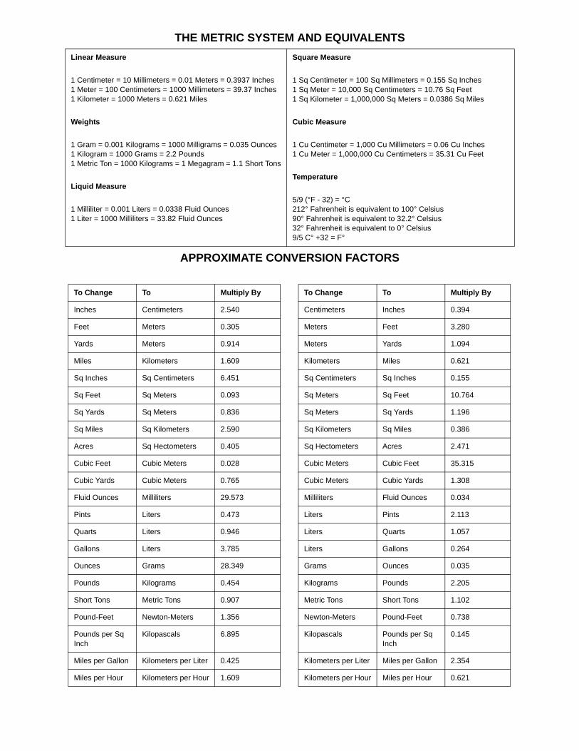
THE METRIC SYSTEM AND EQUIVALENTS
APPROXIMATE CONVERSION FACTORS
Linear Measure
1 Centimeter = 10 Millimeters = 0.01 Meters = 0.3937 Inches1 Meter = 100 Centimeters = 1000 Millimeters = 39.37 Inches1 Kilometer = 1000 Meters = 0.621 Miles
Weights
1 Gram = 0.001 Kilograms = 1000 Milligrams = 0.035 Ounces1 Kilogram = 1000 Grams = 2.2 Pounds1 Metric Ton = 1000 Kilograms = 1 Megagram = 1.1 Short Tons
Liquid Measure
1 Milliliter = 0.001 Liters = 0.0338 Fluid Ounces1 Liter = 1000 Milliliters = 33.82 Fluid Ounces
Square Measure
1 Sq Centimeter = 100 Sq Millimeters = 0.155 Sq Inches1 Sq Meter = 10,000 Sq Centimeters = 10.76 Sq Feet1 Sq Kilometer = 1,000,000 Sq Meters = 0.0386 Sq Miles
Cubic Measure
1 Cu Centimeter = 1,000 Cu Millimeters = 0.06 Cu Inches1 Cu Meter = 1,000,000 Cu Centimeters = 35.31 Cu Feet
Temperature
5/9 (°F - 32) = °C212° Fahrenheit is equivalent to 100° Celsius90° Fahrenheit is equivalent to 32.2° Celsius32° Fahrenheit is equivalent to 0° Celsius9/5 C° +32 = F°
To Change To Multiply By
Inches Centimeters 2.540
Feet Meters 0.305
Yards Meters 0.914
Miles Kilometers 1.609
Sq Inches Sq Centimeters 6.451
Sq Feet Sq Meters 0.093
Sq Yards Sq Meters 0.836
Sq Miles Sq Kilometers 2.590
Acres Sq Hectometers 0.405
Cubic Feet Cubic Meters 0.028
Cubic Yards Cubic Meters 0.765
Fluid Ounces Milliliters 29.573
Pints Liters 0.473
Quarts Liters 0.946
Gallons Liters 3.785
Ounces Grams 28.349
Pounds Kilograms 0.454
Short Tons Metric Tons 0.907
Pound-Feet Newton-Meters 1.356
Pounds per Sq Inch
Kilopascals 6.895
Miles per Gallon Kilometers per Liter 0.425
Miles per Hour Kilometers per Hour 1.609
To Change To Multiply By
Centimeters Inches 0.394
Meters Feet 3.280
Meters Yards 1.094
Kilometers Miles 0.621
Sq Centimeters Sq Inches 0.155
Sq Meters Sq Feet 10.764
Sq Meters Sq Yards 1.196
Sq Kilometers Sq Miles 0.386
Sq Hectometers Acres 2.471
Cubic Meters Cubic Feet 35.315
Cubic Meters Cubic Yards 1.308
Milliliters Fluid Ounces 0.034
Liters Pints 2.113
Liters Quarts 1.057
Liters Gallons 0.264
Grams Ounces 0.035
Kilograms Pounds 2.205
Metric Tons Short Tons 1.102
Newton-Meters Pound-Feet 0.738
Kilopascals Pounds per Sq Inch
0.145
Kilometers per Liter Miles per Gallon 2.354
Kilometers per Hour Miles per Hour 0.621

PIN: 066858-000
This fine document...
Was brought to you by me:
Liberated Manuals -- free army and government manuals
Why do I do it? I am tired of sleazy CD-ROM sellers, who take publicly available information, slap “watermarks” and other junk on it, and sell it. Those masters of search engine manipulation make sure that their sites that sell free information, come up first in search engines. They did not create it... They did not even scan it... Why should they get your money? Why are not letting you give those free manuals to your friends?
I am setting this document FREE. This document was made by the US Government and is NOT protected by Copyright. Feel free to share, republish, sell and so on.
I am not asking you for donations, fees or handouts. If you can, please provide a link to liberatedmanuals.com, so that free manuals come up first in search engines:
<A HREF=http://www.liberatedmanuals.com/>Free Military and Government Manuals</A>
– SincerelyIgor Chudovhttp://igor.chudov.com/
– Chicago Machinery Movers