Embed Size (px)
Citation preview
Blue = Pantone 2728C
Primary/Preferred Branding
Secondary Branding
Tertiary Branding
TECHNICAL MANUAL
Survival Egress Air (SEA MK / LV2)
Rev. 6/17
SEA MK / LV2 Technical Manual2
COPYRIGHT NOTICE
This manual is copyrighted, all rights reserved. It may not, in whole or in part, be copied, photocopied, reproduced, translated or reduced to any electronic medium or machine-readable format without prior consent in writing from Aqua Lung America. It may not be distributed through the internet or computer bulletin board systems without prior consent in writing from Aqua Lung America.
©2017 AQUA LUNG AMERICA. SEA MK / LV2 TECHNICAL MANUAL, PN 108348
You can contact a Technical Adviser via e-mail at:[email protected] [email protected] [email protected]
Warnings, Cautions, & NotesPay special attention to information provided in warnings, cautions and notes that are accompanied by
one of these symbols:
Trademark NoticeAqua Lung® is a registered trademark of Aqua Lung America, Inc.
A WARNING indicates a procedure or situation that, if not avoided, could result in serious injury or death to the user.
A CAUTION indicates any situation or technique that could cause damage to the product and could subsequently result in injury to the user.
A NOTE is used to emphasize important points, tips and reminders.
3
Introduction ........................................................................................................................................4
Disassembly Procedure .....................................................................................................................5
First Stage Disassembly ..................................................................................................................5
Second Stage (MK) Disassembly....................................................................................................8
Second Stage (LV2) Disassembly ...................................................................................................9
Valve Body Disassembly ...............................................................................................................10
Reassembly Procedure ....................................................................................................................10
First Stage Reassembly ................................................................................................................10
First Stage Testing ........................................................................................................................14
Valve Body Reassembly ................................................................................................................15
Second Stage (MK) Reassembly ..................................................................................................16
Second Stage (LV2) Reassembly ..................................................................................................17
Final Testing ......................................................................................................................................19
Table 1: Troubleshooting Guide First Stage...................................................................................20
Table 2: Troubleshooting Guide Second Stage .............................................................................21
Table 3: List of Tools and Service Kits ...........................................................................................22
Table 4: Torque Specifications ........................................................................................................25
Table 5: Test Bench Specifications ................................................................................................25
Table 6: Recommended Cleaners and Lubricants ........................................................................25
Procedure A: Cleaning and Lubricating .........................................................................................26
SEA First Stage Exploded View ......................................................................................................27
MK Second Stage Exploded View ...................................................................................................28
LV2 Second Stage Exploded View ..................................................................................................29
Maintenance Notes ..........................................................................................................................30
CONTENTS
SEA MK / LV2 Technical Manual4
IntroductionThis manual provides factory prescribed procedures for the correct service and repair of this Aqua Lung product. It is not intended to be used as an instructional manual for untrained personnel. The procedures outlined in this manual are to be performed only by personnel who have received Factory Authorized training through an Aqua Lung Service & Repair Seminar. If you do not completely understand all of the procedures outlined in this manual, contact Aqua Lung to speak directly with a Technical Advisor before proceeding any further.
Scheduled ServiceThis product should be given the same care and maintenance as life support equipment. It is therefore important to perform scheduled overhaul service for the complete unit, according to the procedures outlined in this manual on a regularly scheduled basis; once every two years with normal use.
General Guidelines1. In order to correctly perform the procedures outlined in this manual, it is important to follow each step exactly in the order given. Read over the entire manual to become familiar with all procedures before attempting to disassemble the product in this manual and to learn which specialty tools and replacement parts will be required. Keep the manual open beside you for reference while performing each procedure. Do not rely on memory.
2. All service and repair should be carried out in a work area specifically set up and equipped for the task. Adequate lighting, cleanliness and easy access to all required tools are essential for an efficient repair facility.
3. As each unit is disassembled, reusable components should be segregated and not allowed to intermix with non-reusable parts or parts from other units. Delicate parts, including inlet fittings and crowns which contain critical seating surfaces, must be protected and isolated from other parts to prevent damage during the cleaning procedure.
4. Use only genuine Aqua Lung ® parts provided in the over-haul parts kit for this product. DO NOT attempt to substitute an Aqua Lung ® part with another manufacturer’s, regardless of any similarity in shape or size.
5. Do not attempt to reuse mandatory replacement parts under any circumstances, regardless of the amount of use the product has received since it was manufactured or last serviced.
6. When reassembling, it is important to follow every torque specification prescribed in this manual, using a calibrated torque wrench. Most parts are made of aluminum, marine brass or plastic and can be permanently damaged by excessive stress.
Pinch MethodPress upwards on sides of o-ring to create a protrusion. Grab o-ring or insert o-ring tool at protrusion.
General ConventionsUnless otherwise instructed, the following terminology and techniques are assumed:
1. When instructed to remove, unscrew or loosen a threaded part, turn the part counter-clockwise.When instructed to install, screw or tighten a threaded part, turn the part clockwise.
2. When instructed to "OPEN" the handwheel, turn the handwheel counter-clockwise. The red indicator ring will not be visible in the handwheel window, this indicates the unit is in the "ON" position.When instructed to "CLOSE" the handwheel, turn the handwheel clockwise. The red indicator ring will be visible in the handwheel window, this indicates the unit is in the "OFF" position.
3. The method used to depressurize your system will depend on its configuration:
• SEA w/ handwheel: Depress second stage purge button for 5 seconds and release for 5 seconds. Repeat this procedure until the system is depressurize.
• SEA w/o handwheel: Breathe the unit down by taking 5 breaths from the second stage and pause for 5 seconds. Repeat this procedure until the system is depressurized.
4. When instructed to fill or refill the cylinder, 3000 PSI (207 BAR) will be the standard fill pressure used for testing purposes in this manual. Upon completion of all testing, fill the cylinder to its full capacity as marked. (Reference the Filling Procedures section of the User's Manual). 5. The following acronyms are used throughout the manual: LP is Low Pressure; MP is Medium Pressure; and HP is High Pressure.
6. Numbers in parentheses reference the key numbers on the exploded parts schematics. For example, in the statement, “... remove the o-ring (7) from the crown (8) “...the number 7 is the key number to the crown o-ring.
7. When instructed to remove an o-ring, use the pinch method (see illustration below) or use a brass or plastic o-ring removal tool. Avoid using hardened steel picks (unless directed), as they may damage the o-ring sealing surface. All o-rings that are removed are discarded and replaced with brand new o-rings.
5
DISASSEMBLY PROCEDURE
First Stage Disassembly
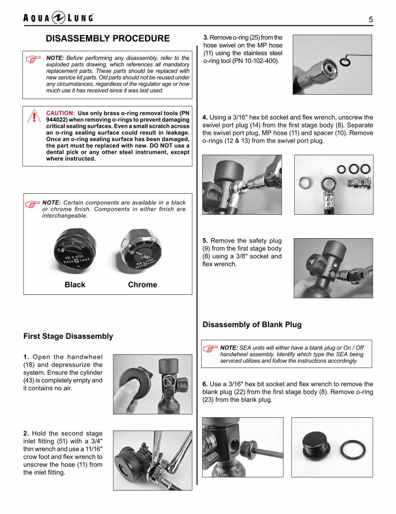
1. Open the handwheel (18) and depressurize the system. Ensure the cylinder (43) is completely empty and it contains no air.
2. Hold the second stage inlet fitting (51) with a 3/4" thin wrench and use a 11/16" crow foot and flex wrench to unscrew the hose (11) from the inlet fitting.
3. Remove o-ring (25) from the hose swivel on the MP hose (11) using the stainless steel o-ring tool (PN 10-102-400).
CAUTION: Use only brass o-ring removal tools (PN 944022) when removing o-rings to prevent damaging critical sealing surfaces. Even a small scratch across an o-ring sealing surface could result in leakage. Once an o-ring sealing surface has been damaged, the part must be replaced with new. DO NOT use a dental pick or any other steel instrument, except where instructed.
NOTE: Before performing any disassembly, refer to the exploded parts drawing, which references all mandatory replacement parts. These parts should be replaced with new service kit parts. Old parts should not be reused under any circumstances, regardless of the regulator age or how much use it has received since it was last used.
4. Using a 3/16" hex bit socket and flex wrench, unscrew the swivel port plug (14) from the first stage body (8). Separate the swivel port plug, MP hose (11) and spacer (10). Remove o-rings (12 & 13) from the swivel port plug.
5. Remove the safety plug (9) from the first stage body (8) using a 3/8" socket and flex wrench.
NOTE: SEA units will either have a blank plug or On / Off handwheel assembly. Identify which type the SEA being serviced utilizes and follow the instructions accordingly.
Disassembly of Blank Plug
6. Use a 3/16" hex bit socket and flex wrench to remove the blank plug (22) from the first stage body (8). Remove o-ring (23) from the blank plug.
NOTE: Certain components are available in a black or chrome finish. Components in either finish are interchangeable.
Black Chrome
SEA MK / LV2 Technical Manual6
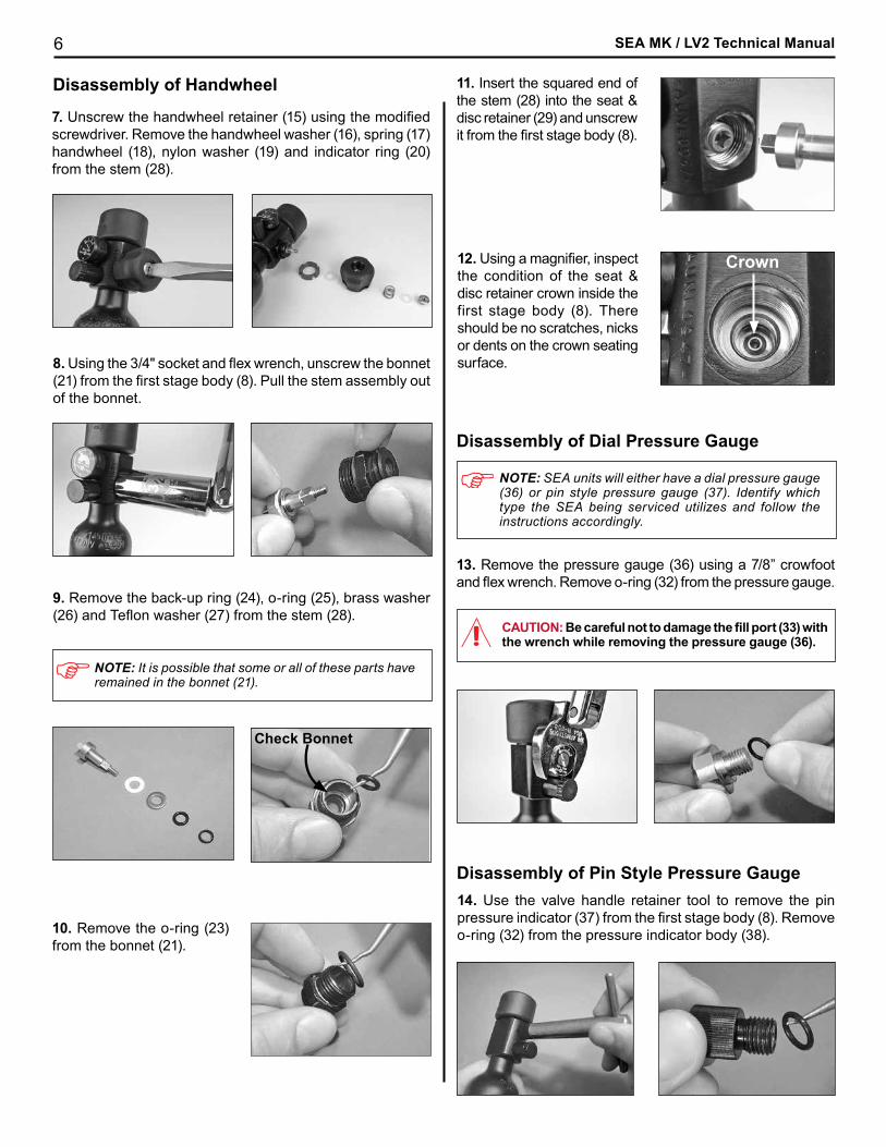
9. Remove the back-up ring (24), o-ring (25), brass washer (26) and Teflon washer (27) from the stem (28).
Check Bonnet
NOTE: It is possible that some or all of these parts have remained in the bonnet (21).
10. Remove the o-ring (23) from the bonnet (21).
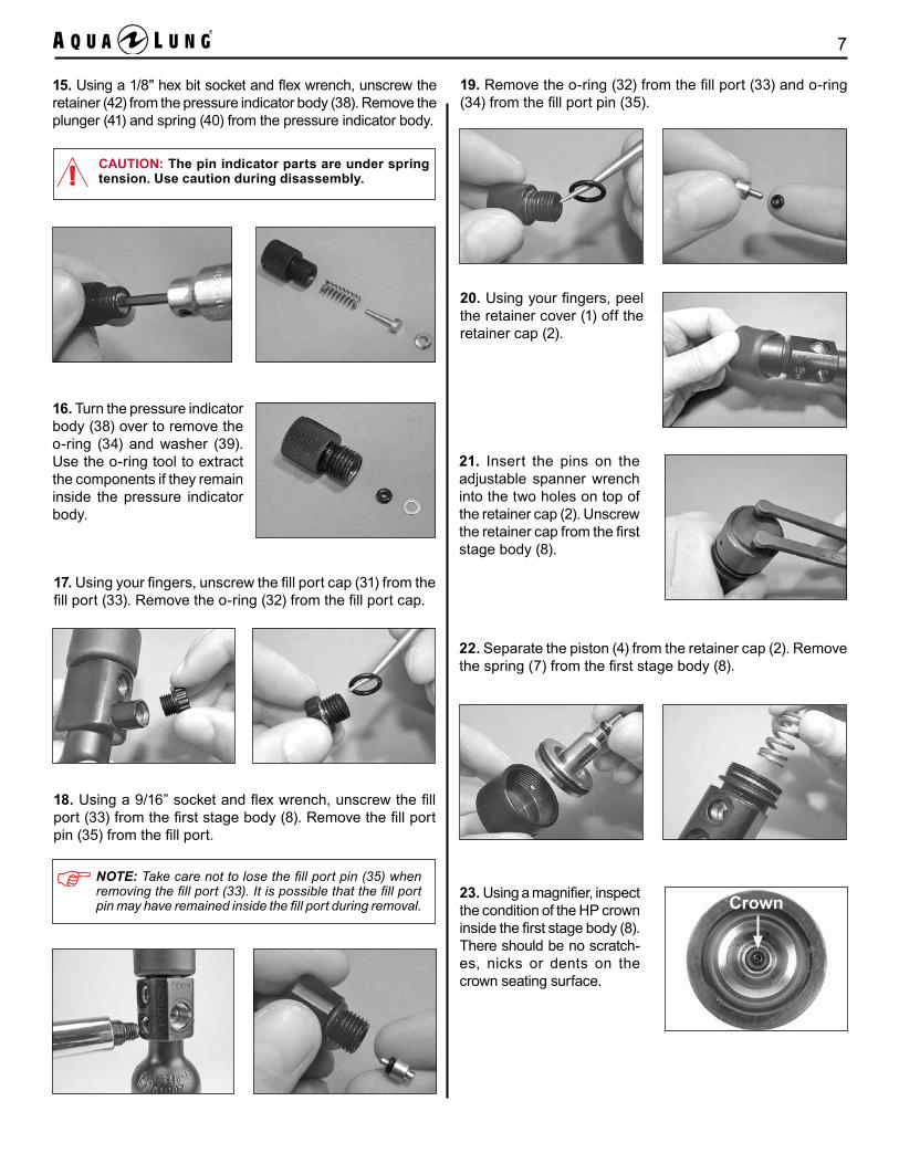
11. Insert the squared end of the stem (28) into the seat & disc retainer (29) and unscrew it from the first stage body (8).
13. Remove the pressure gauge (36) using a 7/8” crowfoot and flex wrench. Remove o-ring (32) from the pressure gauge.
Crown12. Using a magnifier, inspect the condition of the seat & disc retainer crown inside the first stage body (8). There should be no scratches, nicks or dents on the crown seating surface.
CAUTION: Be careful not to damage the fill port (33) with the wrench while removing the pressure gauge (36).
8. Using the 3/4" socket and flex wrench, unscrew the bonnet (21) from the first stage body (8). Pull the stem assembly out of the bonnet.
7. Unscrew the handwheel retainer (15) using the modified screwdriver. Remove the handwheel washer (16), spring (17)handwheel (18), nylon washer (19) and indicator ring (20) from the stem (28).
Disassembly of Handwheel
NOTE: SEA units will either have a dial pressure gauge (36) or pin style pressure gauge (37). Identify which type the SEA being serviced utilizes and follow the instructions accordingly.
Disassembly of Dial Pressure Gauge
Disassembly of Pin Style Pressure Gauge14. Use the valve handle retainer tool to remove the pin pressure indicator (37) from the first stage body (8). Remove o-ring (32) from the pressure indicator body (38).
7
17. Using your fingers, unscrew the fill port cap (31) from the fill port (33). Remove the o-ring (32) from the fill port cap.
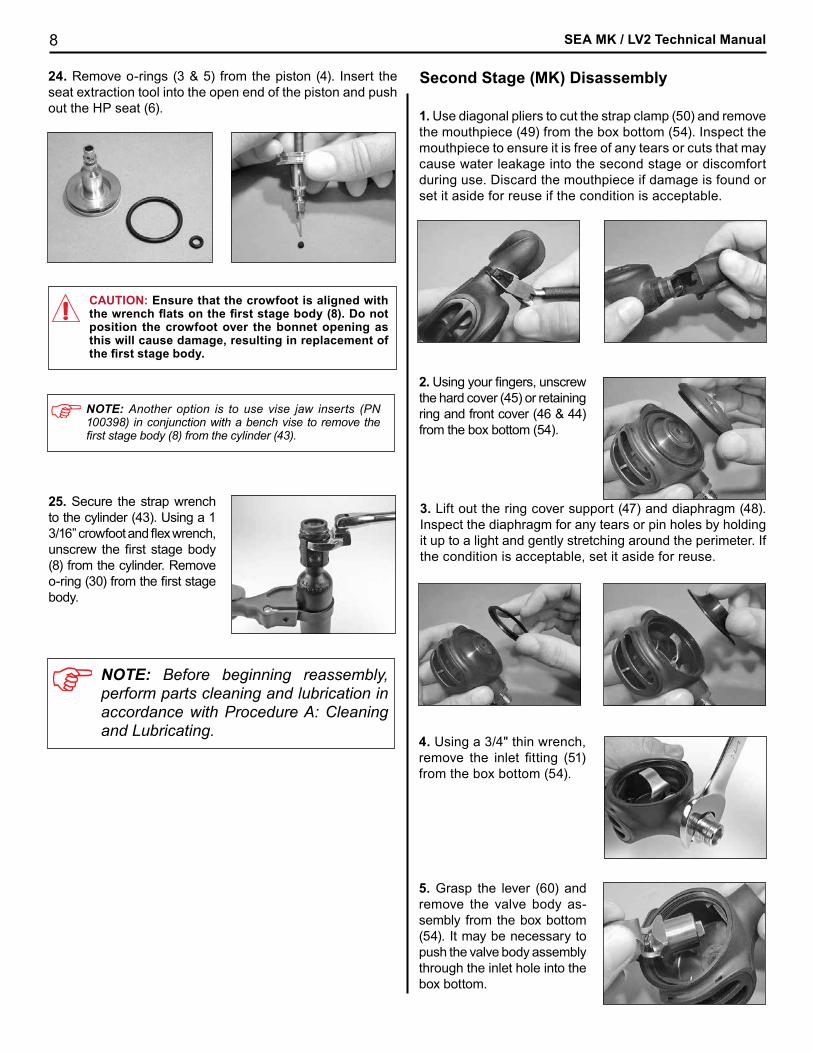
CAUTION: The pin indicator parts are under spring tension. Use caution during disassembly.
15. Using a 1/8" hex bit socket and flex wrench, unscrew the retainer (42) from the pressure indicator body (38). Remove the plunger (41) and spring (40) from the pressure indicator body.
16. Turn the pressure indicator body (38) over to remove the o-ring (34) and washer (39). Use the o-ring tool to extract the components if they remain inside the pressure indicator body.
21. Insert the pins on the adjustable spanner wrench into the two holes on top of the retainer cap (2). Unscrew the retainer cap from the first stage body (8).
20. Using your fingers, peel the retainer cover (1) off the retainer cap (2).
18. Using a 9/16” socket and flex wrench, unscrew the fill port (33) from the first stage body (8). Remove the fill port pin (35) from the fill port.
NOTE: Take care not to lose the fill port pin (35) when removing the fill port (33). It is possible that the fill port pin may have remained inside the fill port during removal.
19. Remove the o-ring (32) from the fill port (33) and o-ring (34) from the fill port pin (35).
22. Separate the piston (4) from the retainer cap (2). Remove the spring (7) from the first stage body (8).
23. Using a magnifier, inspect the condition of the HP crown inside the first stage body (8). There should be no scratch-es, nicks or dents on the crown seating surface.
Crown
SEA MK / LV2 Technical Manual8
25. Secure the strap wrench to the cylinder (43). Using a 1 3/16” crowfoot and flex wrench, unscrew the first stage body (8) from the cylinder. Remove o-ring (30) from the first stage body.
NOTE: Before beginning reassembly, perform parts cleaning and lubrication in accordance with Procedure A: Cleaning and Lubricating.
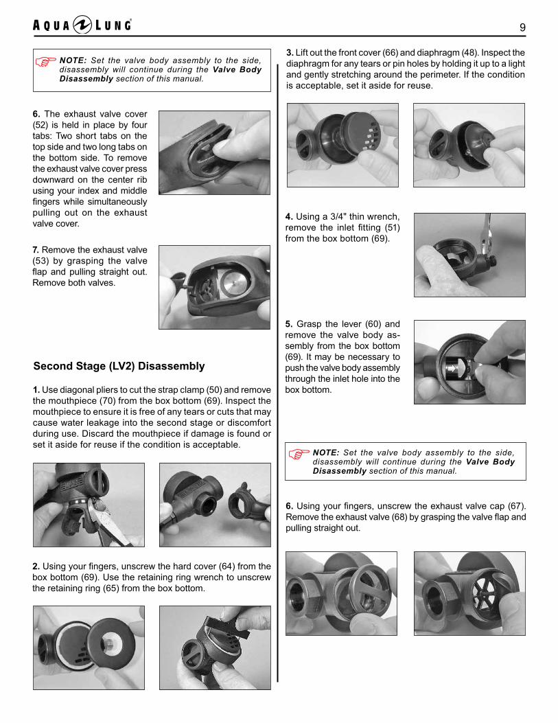
4. Using a 3/4" thin wrench, remove the inlet fitting (51) from the box bottom (54).
5. Grasp the lever (60) and remove the valve body as-sembly from the box bottom (54). It may be necessary to push the valve body assembly through the inlet hole into the box bottom.
3. Lift out the ring cover support (47) and diaphragm (48). Inspect the diaphragm for any tears or pin holes by holding it up to a light and gently stretching around the perimeter. If the condition is acceptable, set it aside for reuse.
Second Stage (MK) Disassembly
1. Use diagonal pliers to cut the strap clamp (50) and remove the mouthpiece (49) from the box bottom (54). Inspect the mouthpiece to ensure it is free of any tears or cuts that may cause water leakage into the second stage or discomfort during use. Discard the mouthpiece if damage is found or set it aside for reuse if the condition is acceptable.
2. Using your fingers, unscrew the hard cover (45) or retaining ring and front cover (46 & 44) from the box bottom (54).
CAUTION: Ensure that the crowfoot is aligned with the wrench flats on the first stage body (8). Do not position the crowfoot over the bonnet opening as this will cause damage, resulting in replacement of the first stage body.
NOTE: Another option is to use vise jaw inserts (PN 100398) in conjunction with a bench vise to remove the first stage body (8) from the cylinder (43).
24. Remove o-rings (3 & 5) from the piston (4). Insert the seat extraction tool into the open end of the piston and push out the HP seat (6).
9
6. The exhaust valve cover (52) is held in place by four tabs: Two short tabs on the top side and two long tabs on the bottom side. To remove the exhaust valve cover press downward on the center rib using your index and middle fingers while simultaneously pulling out on the exhaust valve cover.
7. Remove the exhaust valve (53) by grasping the valve flap and pulling straight out. Remove both valves.
Second Stage (LV2) Disassembly
1. Use diagonal pliers to cut the strap clamp (50) and remove the mouthpiece (70) from the box bottom (69). Inspect the mouthpiece to ensure it is free of any tears or cuts that may cause water leakage into the second stage or discomfort during use. Discard the mouthpiece if damage is found or set it aside for reuse if the condition is acceptable.
2. Using your fingers, unscrew the hard cover (64) from the box bottom (69). Use the retaining ring wrench to unscrew the retaining ring (65) from the box bottom.
3. Lift out the front cover (66) and diaphragm (48). Inspect the diaphragm for any tears or pin holes by holding it up to a light and gently stretching around the perimeter. If the condition is acceptable, set it aside for reuse.
4. Using a 3/4" thin wrench, remove the inlet fitting (51) from the box bottom (69).
5. Grasp the lever (60) and remove the valve body as-sembly from the box bottom (69). It may be necessary to push the valve body assembly through the inlet hole into the box bottom.
6. Using your fingers, unscrew the exhaust valve cap (67). Remove the exhaust valve (68) by grasping the valve flap and pulling straight out.
NOTE: Set the valve body assembly to the side, disassembly will continue during the Valve Body Disassembly section of this manual.
NOTE: Set the valve body assembly to the side, disassembly will continue during the Valve Body Disassembly section of this manual.
SEA MK / LV2 Technical Manual10
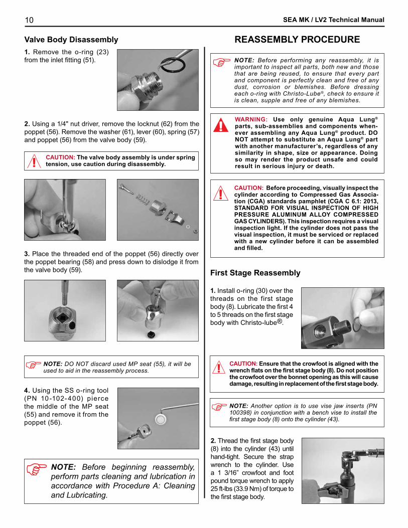
3. Place the threaded end of the poppet (56) directly over the poppet bearing (58) and press down to dislodge it from the valve body (59).
4. Using the SS o-ring tool (PN 10 -102- 400) pierce the middle of the MP seat (55) and remove it from the poppet (56).
NOTE: DO NOT discard used MP seat (55), it will be used to aid in the reassembly process.
NOTE: Before beginning reassembly, perform parts cleaning and lubrication in accordance with Procedure A: Cleaning and Lubricating.
REASSEMBLY PROCEDURE
CAUTION: Before proceeding, visually inspect the cylinder according to Compressed Gas Associa-tion (CGA) standards pamphlet (CGA C 6.1: 2013, STANDARD FOR VISUAL INSPECTION OF HIGH PRESSURE ALUMINUM ALLOY COMPRESSED GAS CYLINDERS). This inspection requires a visual inspection light. If the cylinder does not pass the visual inspection, it must be serviced or replaced with a new cylinder before it can be assembled and filled.
NOTE: Before performing any reassembly, it is important to inspect all parts, both new and those that are being reused, to ensure that every part and component is perfectly clean and free of any dust, corrosion or blemishes. Before dressing each o-ring with Christo-Lube®, check to ensure it is clean, supple and free of any blemishes.
WARNING: Use only genuine Aqua Lung® parts, sub-assemblies and components when-ever assembling any Aqua Lung® product. DO NOT attempt to substitute an Aqua Lung® part with another manufacturer’s, regardless of any similarity in shape, size or appearance. Doing so may render the product unsafe and could result in serious injury or death.
1. Install o-ring (30) over the threads on the first stage body (8). Lubricate the first 4 to 5 threads on the first stage body with Christo-lube®.
2. Thread the first stage body (8) into the cylinder (43) until hand-tight. Secure the strap wrench to the cylinder. Use a 1 3/16” crowfoot and foot pound torque wrench to apply 25 ft-lbs (33.9 Nm) of torque to the first stage body.
CAUTION: Ensure that the crowfoot is aligned with the wrench flats on the first stage body (8). Do not position the crowfoot over the bonnet opening as this will cause damage, resulting in replacement of the first stage body.
NOTE: Another option is to use vise jaw inserts (PN 100398) in conjunction with a bench vise to install the first stage body (8) onto the cylinder (43).
Valve Body Disassembly
CAUTION: The valve body assembly is under spring tension, use caution during disassembly.
2. Using a 1/4" nut driver, remove the locknut (62) from the poppet (56). Remove the washer (61), lever (60), spring (57) and poppet (56) from the valve body (59).
1. Remove the o-ring (23) from the inlet fitting (51).
First Stage Reassembly
11
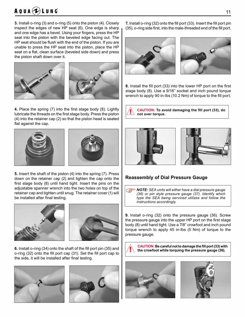
3. Install o-ring (3) and o-ring (5) onto the piston (4). Closely inspect the edges of new HP seat (6). One edge is sharp and one edge has a bevel. Using your fingers, press the HP seat into the piston with the beveled edge facing out. The HP seat should be flush with the end of the piston. If you are unable to press the HP seat into the piston, place the HP seat on a flat, clean surface (beveled side down) and press the piston shaft down over it.
4. Place the spring (7) into the first stage body (8). Lightly lubricate the threads on the first stage body. Press the piston (4) into the retainer cap (2) so that the piston head is seated flat against the cap.
6. Install o-ring (34) onto the shaft of the fill port pin (35) and o-ring (32) onto the fill port cap (31). Set the fill port cap to the side, it will be installed after final testing.
7. Install o-ring (32) onto the fill port (33). Insert the fill port pin (35), o-ring side first, into the male-threaded end of the fill port.
CAUTION: To avoid damaging the fill port (33), do not over torque.
5. Insert the shaft of the piston (4) into the spring (7). Press down on the retainer cap (2) and tighten the cap onto the first stage body (8) until hand tight. Insert the pins on the adjustable spanner wrench into the two holes on top of the retainer cap and tighten until snug. The retainer cover (1) will be installed after final testing.
8. Install the fill port (33) into the lower HP port on the first stage body (8). Use a 9/16” socket and inch pound torque wrench to apply 90 in-lbs (10.2 Nm) of torque to the fill port.
CAUTION: Be careful not to damage the fill port (33) with the crowfoot while torquing the pressure gauge (36).
Reassembly of Dial Pressure Gauge
9. Install o-ring (32) onto the pressure gauge (36). Screw the pressure gauge into the upper HP port on the first stage body (8) until hand tight. Use a 7/8” crowfoot and inch pound torque wrench to apply 45 in-lbs (5 Nm) of torque to the pressure gauge.
NOTE: SEA units will either have a dial pressure gauge (36) or pin style pressure gauge (37). Identify which type the SEA being serviced utilizes and follow the instructions accordingly.
SEA MK / LV2 Technical Manual12
Reassembly of Pin Style Pressure Gauge
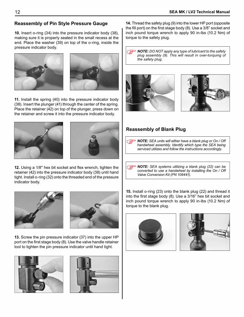
10. Insert o-ring (34) into the pressure indicator body (38), making sure it is properly seated in the small recess at the end. Place the washer (39) on top of the o-ring, inside the pressure indicator body.
11. Install the spring (40) into the pressure indicator body (38). Insert the plunger (41) through the center of the spring. Place the retainer (42) on top of the plunger, press down on the retainer and screw it into the pressure indicator body.
12. Using a 1/8" hex bit socket and flex wrench, tighten the retainer (42) into the pressure indicator body (38) until hand tight. Install o-ring (32) onto the threaded end of the pressure indicator body.
13. Screw the pin pressure indicator (37) into the upper HP port on the first stage body (8). Use the valve handle retainer tool to tighten the pin pressure indicator until hand tight.
14. Thread the safety plug (9) into the lower HP port (opposite the fill port) on the first stage body (8). Use a 3/8” socket and inch pound torque wrench to apply 90 in-lbs (10.2 Nm) of torque to the safety plug.
NOTE: DO NOT apply any type of lubricant to the safety plug assembly (9). This will result in over-torquing of the safety plug.
NOTE: SEA units will either have a blank plug or On / Off handwheel assembly. Identify which type the SEA being serviced utilizes and follow the instructions accordingly.
Reassembly of Blank Plug
15. Install o-ring (23) onto the blank plug (22) and thread it into the first stage body (8). Use a 3/16” hex bit socket and inch pound torque wrench to apply 90 in-lbs (10.2 Nm) of torque to the blank plug.
NOTE: SEA systems utilizing a blank plug (22) can be converted to use a handwheel by installing the On / Off Valve Conversion Kit (PN 108441).
13
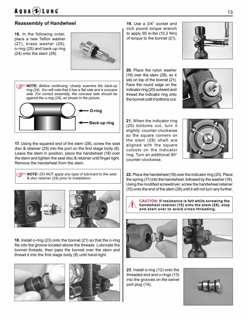
NOTE: Before continuing, closely examine the back-up ring (24). You will note that it has a flat side and a concave side. For correct assembly, the concave side should be against the o-ring (25), as shown in the picture.
O-ring
Back-up ring
17. Using the squared end of the stem (28), screw the seat disc & retainer (29) into the port on the first stage body (8). Leave the stem in position, place the handwheel (18) over the stem and tighten the seat disc & retainer until finger tight. Remove the handwheel from the stem.
18. Install o-ring (23) onto the bonnet (21) so that the o-ring fits into the groove located above the threads. Lubricate the bonnet threads, then pass the bonnet over the stem and thread it into the first stage body (8) until hand-tight.
19. Use a 3/4” socket and inch pound torque wrench to apply 90 in-lbs (10.2 Nm) of torque to the bonnet (21).
20. Place the nylon washer (19) over the stem (28), so it sits on top of the bonnet (21). Face the round edge on the indicator ring (20) outward and thread the indicator ring onto the bonnet until it bottoms out.
21. When the indicator ring (20) bottoms out, turn it slightly counter-clockwise so the square corners on the stem (28) shaf t are al igned with the square cutouts on the indicator ring. Turn an additional 90° counter-clockwise.
22. Place the handwheel (18) over the indicator ring (20). Place the spring (17) into the handwheel, followed by the washer (16). Using the modified screwdriver, screw the handwheel retainer (15) onto the end of the stem (28) until it will not turn any further.
CAUTION: If resistance is felt while screwing the handwheel retainer (15) onto the stem (28), stop and start over to avoid cross threading.
23. Install o-ring (12) onto the threaded end and o-rings (13) into the grooves on the swivel port plug (14).
16. In the following order, place a new Teflon washer (27), brass washer (26), o-ring (25) and back-up ring (24) onto the stem (28).
Reassembly of Handwheel
NOTE: DO NOT apply any type of lubricant to the seat & disc retainer (29) prior to installation.
SEA MK / LV2 Technical Manual14
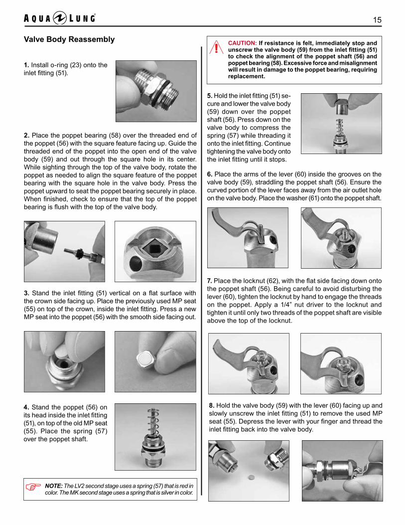
NOTE: O-ring (25) for the second stage swivel end of the MP hose (11) is in the second stage overhaul kit PN108343.
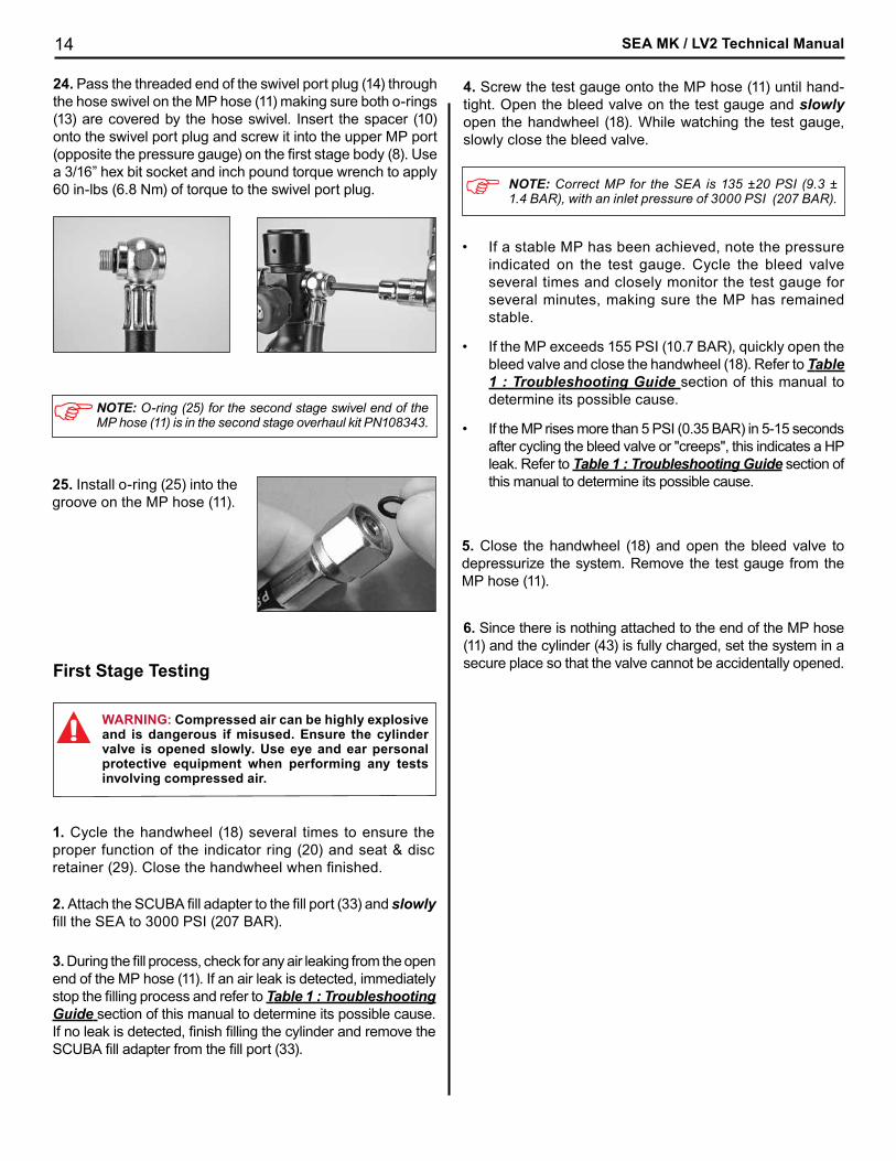
24. Pass the threaded end of the swivel port plug (14) through the hose swivel on the MP hose (11) making sure both o-rings (13) are covered by the hose swivel. Insert the spacer (10) onto the swivel port plug and screw it into the upper MP port (opposite the pressure gauge) on the first stage body (8). Use a 3/16” hex bit socket and inch pound torque wrench to apply 60 in-lbs (6.8 Nm) of torque to the swivel port plug.
2. Attach the SCUBA fill adapter to the fill port (33) and slowly fill the SEA to 3000 PSI (207 BAR).
3. During the fill process, check for any air leaking from the open end of the MP hose (11). If an air leak is detected, immediately stop the filling process and refer to Table 1 : Troubleshooting Guide section of this manual to determine its possible cause. If no leak is detected, finish filling the cylinder and remove the SCUBA fill adapter from the fill port (33).
1. Cycle the handwheel (18) several times to ensure the proper function of the indicator ring (20) and seat & disc retainer (29). Close the handwheel when finished.
First Stage Testing
NOTE: Correct MP for the SEA is 135 ±20 PSI (9.3 ± 1.4 BAR), with an inlet pressure of 3000 PSI (207 BAR).
5. Close the handwheel (18) and open the bleed valve to depressurize the system. Remove the test gauge from the MP hose (11).
6. Since there is nothing attached to the end of the MP hose (11) and the cylinder (43) is fully charged, set the system in a secure place so that the valve cannot be accidentally opened.
25. Install o-ring (25) into the groove on the MP hose (11).
WARNING: Compressed air can be highly explosive and is dangerous if misused. Ensure the cylinder valve is opened slowly. Use eye and ear personal protective equipment when performing any tests involving compressed air.
4. Screw the test gauge onto the MP hose (11) until hand-tight. Open the bleed valve on the test gauge and slowly open the handwheel (18). While watching the test gauge, slowly close the bleed valve.
• If a stable MP has been achieved, note the pressure indicated on the test gauge. Cycle the bleed valve several times and closely monitor the test gauge for several minutes, making sure the MP has remained stable.
• If the MP exceeds 155 PSI (10.7 BAR), quickly open the bleed valve and close the handwheel (18). Refer to Table 1 : Troubleshooting Guide section of this manual to determine its possible cause.
• If the MP rises more than 5 PSI (0.35 BAR) in 5-15 seconds after cycling the bleed valve or "creeps", this indicates a HP leak. Refer to Table 1 : Troubleshooting Guide section of this manual to determine its possible cause.
15
Valve Body Reassembly
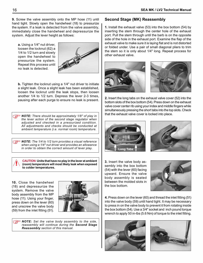
2. Place the poppet bearing (58) over the threaded end of the poppet (56) with the square feature facing up. Guide the threaded end of the poppet into the open end of the valve body (59) and out through the square hole in its center. While sighting through the top of the valve body, rotate the poppet as needed to align the square feature of the poppet bearing with the square hole in the valve body. Press the poppet upward to seat the poppet bearing securely in place. When finished, check to ensure that the top of the poppet bearing is flush with the top of the valve body.
1. Install o-ring (23) onto the inlet fitting (51).
3. Stand the inlet fitting (51) vertical on a flat surface with the crown side facing up. Place the previously used MP seat (55) on top of the crown, inside the inlet fitting. Press a new MP seat into the poppet (56) with the smooth side facing out.
4. Stand the poppet (56) on its head inside the inlet fitting (51), on top of the old MP seat (55). Place the spring (57) over the poppet shaft.
5. Hold the inlet fitting (51) se-cure and lower the valve body (59) down over the poppet shaft (56). Press down on the valve body to compress the spring (57) while threading it onto the inlet fitting. Continue tightening the valve body onto the inlet fitting until it stops.
CAUTION: If resistance is felt, immediately stop and unscrew the valve body (59) from the inlet fitting (51)to check the alignment of the poppet shaft (56) and poppet bearing (58). Excessive force and misalignment will result in damage to the poppet bearing, requiring replacement.
6. Place the arms of the lever (60) inside the grooves on the valve body (59), straddling the poppet shaft (56). Ensure the curved portion of the lever faces away from the air outlet hole on the valve body. Place the washer (61) onto the poppet shaft.
7. Place the locknut (62), with the flat side facing down onto the poppet shaft (56). Being careful to avoid disturbing the lever (60), tighten the locknut by hand to engage the threads on the poppet. Apply a 1/4” nut driver to the locknut and tighten it until only two threads of the poppet shaft are visible above the top of the locknut.
8. Hold the valve body (59) with the lever (60) facing up and slowly unscrew the inlet fitting (51) to remove the used MP seat (55). Depress the lever with your finger and thread the inlet fitting back into the valve body.
NOTE: The LV2 second stage uses a spring (57) that is red in color. The MK second stage uses a spring that is silver in color.
SEA MK / LV2 Technical Manual16
10. Close the handwheel (18) and depressurize the system. Remove the valve body assembly from the MP hose (11). Using your finger, press down on the lever (60) and unscrew the valve body (59) from the inlet fitting (51).
Second Stage (MK) Reassembly
Long Tabs
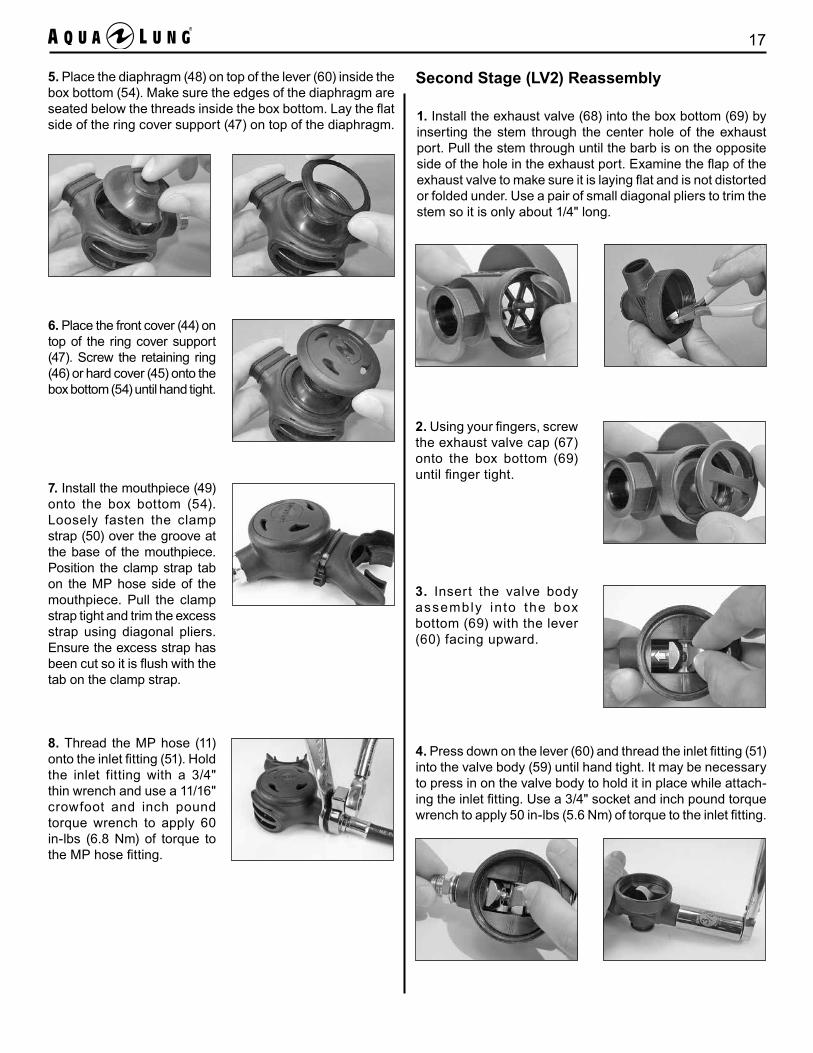
1. Install the exhaust valve (53) into the box bottom (54) by inserting the stem through the center hole of the exhaust port. Pull the stem through until the barb is on the opposite side of the hole in the exhaust port. Examine the flap of the exhaust valve to make sure it is laying flat and is not distorted or folded under. Use a pair of small diagonal pliers to trim the stem so it is only about 1/4" long. Repeat process for other exhaust valve.
2. Insert the long tabs on the exhaust valve cover (52) into the bottom slots of the box bottom (54). Press down on the exhaust valve cover center rib using your index and middle fingers while simultaneously pressing the short tabs into the top slots. Check that the exhaust valve cover is locked into place.
3. Insert the valve body as-sembly into the box bottom (54) with the lever (60) facing upward. Ensure the valve body assembly is seated between the molded slots in the box bottom.
4. Press down on the lever (60) and thread the inlet fitting (51) into the valve body (59) until hand tight. It may be necessary to press in on the valve body to prevent it from rotating inside the box bottom (54). Use a 3/4" socket and inch pound torque wrench to apply 50 in-lbs (5.6 Nm) of torque to the inlet fitting.
NOTE: Set the valve body assembly to the side, reassembly will continue during the Second Stage Reassembly section of this manual.
9. Screw the valve assembly onto the MP hose (11) until hand tight. Slowly open the handwheel (18) to pressurize the system. If a leak is detected from the valve assembly, immediately close the handwheel and depressurize the system. Adjust the lever height as follows:
a. Using a 1/4" nut driver, loosen the locknut (62) a 1/4 to 1/2 turn and slowly open the handwheel to pressurize the system. Repeat this process until no leak is detected.
b. Tighten the locknut using a 1/4" nut driver to initiate a slight leak. Once a slight leak has been established, loosen the locknut until the leak stops, then loosen another 1/4 to 1/2 turn. Depress the lever 2-3 times, pausing after each purge to ensure no leak is present.
NOTE: There should be approximately 1/8" of play in the lever action of the second stage regulator when adjusted and checked in a pressurized condition. All adjustments and checks should be conducted at ambient temperature (i.e. normal room) temperature.
NOTE: The 1/4 to 1/2 turn provides a visual reference when using a 1/4" nut driver and provides an allowance in order to obtain the correct amount of lever play.
CAUTION: Units that have no play in the lever at ambient (room) temperature will most likely leak when exposed to colder temperatures.
17
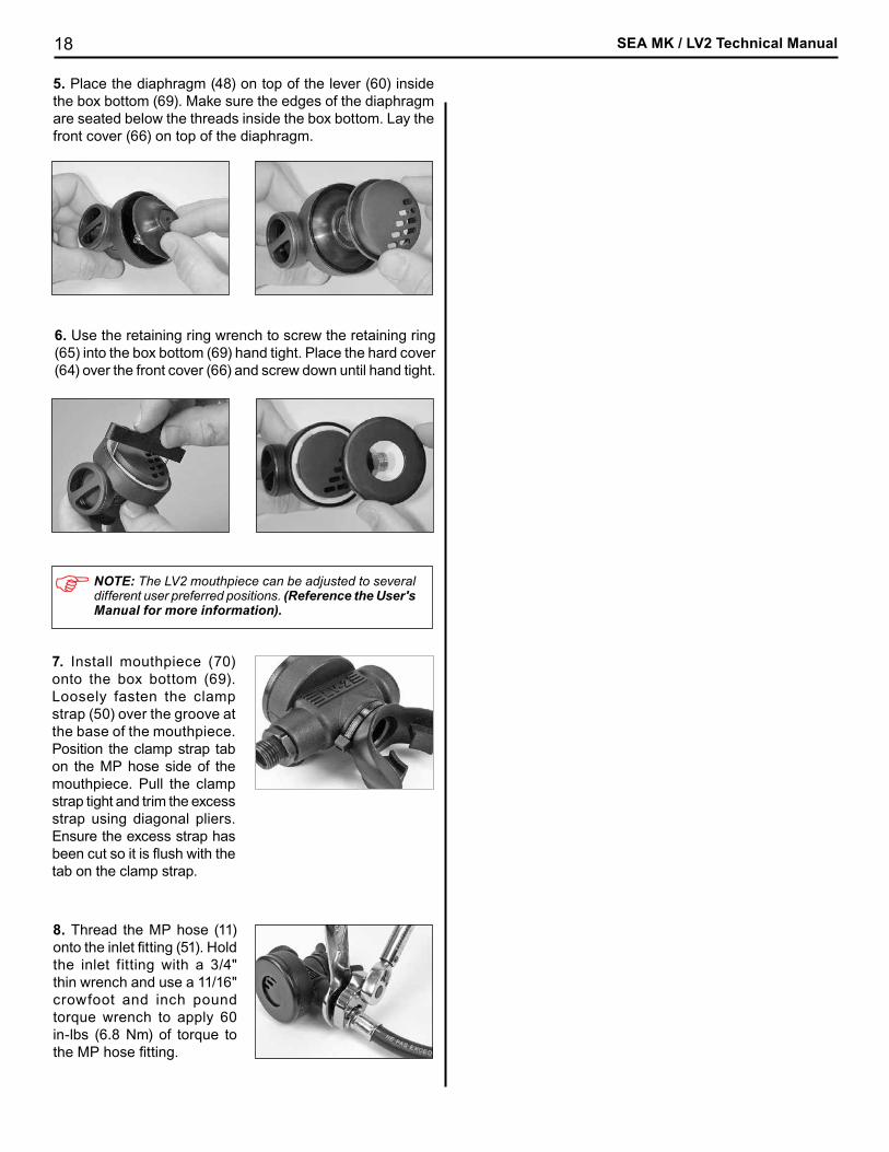
5. Place the diaphragm (48) on top of the lever (60) inside the box bottom (54). Make sure the edges of the diaphragm are seated below the threads inside the box bottom. Lay the flat side of the ring cover support (47) on top of the diaphragm.
6. Place the front cover (44) on top of the ring cover support (47). Screw the retaining ring (46) or hard cover (45) onto the box bottom (54) until hand tight.
7. Install the mouthpiece (49) onto the box bottom (54). Loosely fasten the clamp strap (50) over the groove at the base of the mouthpiece. Position the clamp strap tab on the MP hose side of the mouthpiece. Pull the clamp strap tight and trim the excess strap using diagonal pliers. Ensure the excess strap has been cut so it is flush with the tab on the clamp strap.
Second Stage (LV2) Reassembly
1. Install the exhaust valve (68) into the box bottom (69) by inserting the stem through the center hole of the exhaust port. Pull the stem through until the barb is on the opposite side of the hole in the exhaust port. Examine the flap of the exhaust valve to make sure it is laying flat and is not distorted or folded under. Use a pair of small diagonal pliers to trim the stem so it is only about 1/4" long.
2. Using your fingers, screw the exhaust valve cap (67) onto the box bottom (69) until finger tight.
3. Insert the valve body assembly into the box bottom (69) with the lever (60) facing upward.
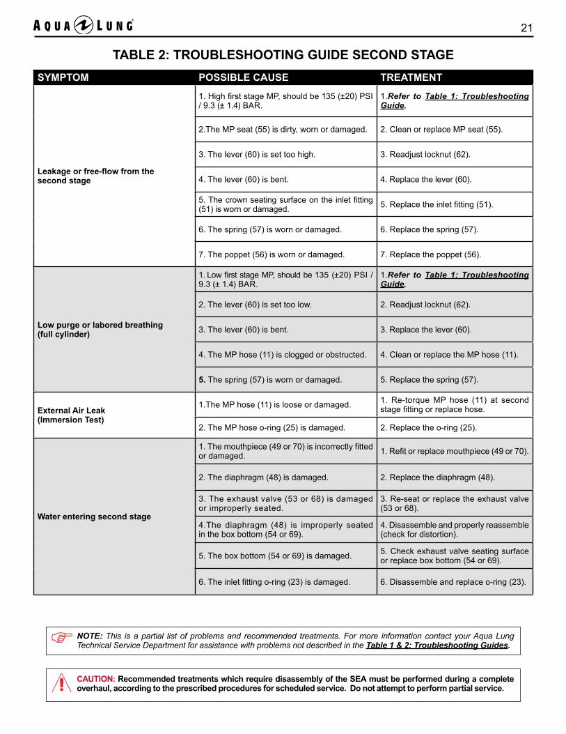
8. Thread the MP hose (11) onto the inlet fitting (51). Hold the inlet fitting with a 3/4" thin wrench and use a 11/16" crowfoot and inch pound torque wrench to apply 60 in-lbs (6.8 Nm) of torque to the MP hose fitting.
4. Press down on the lever (60) and thread the inlet fitting (51) into the valve body (59) until hand tight. It may be necessary to press in on the valve body to hold it in place while attach-ing the inlet fitting. Use a 3/4" socket and inch pound torque wrench to apply 50 in-lbs (5.6 Nm) of torque to the inlet fitting.
SEA MK / LV2 Technical Manual18
8. Thread the MP hose (11) onto the inlet fitting (51). Hold the inlet fitting with a 3/4" thin wrench and use a 11/16" crowfoot and inch pound torque wrench to apply 60 in-lbs (6.8 Nm) of torque to the MP hose fitting.
5. Place the diaphragm (48) on top of the lever (60) inside the box bottom (69). Make sure the edges of the diaphragm are seated below the threads inside the box bottom. Lay the front cover (66) on top of the diaphragm.
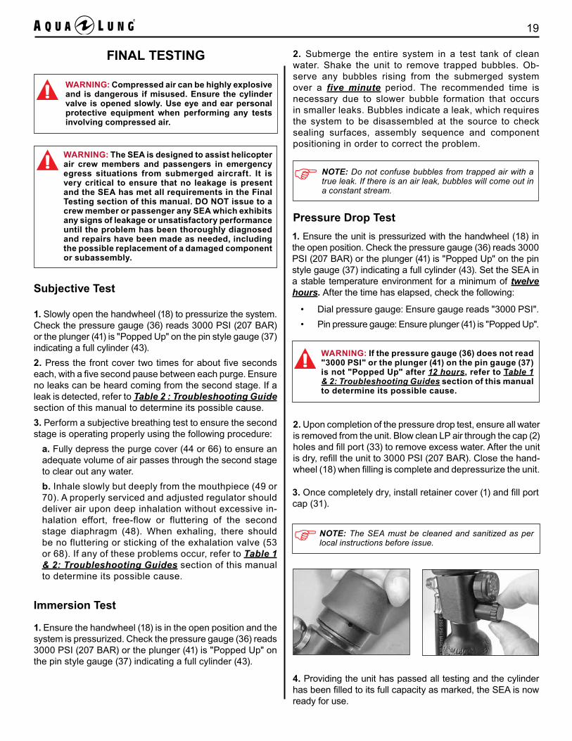
6. Use the retaining ring wrench to screw the retaining ring (65) into the box bottom (69) hand tight. Place the hard cover (64) over the front cover (66) and screw down until hand tight.
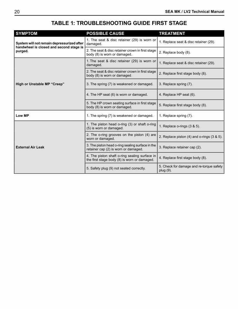
7. Install mouthpiece (70) onto the box bottom (69). Loosely fasten the clamp strap (50) over the groove at the base of the mouthpiece. Position the clamp strap tab on the MP hose side of the mouthpiece. Pull the clamp strap tight and trim the excess strap using diagonal pliers. Ensure the excess strap has been cut so it is flush with the tab on the clamp strap.
NOTE: The LV2 mouthpiece can be adjusted to several different user preferred positions. (Reference the User's Manual for more information).
19
FINAL TESTING
Subjective Test
1. Slowly open the handwheel (18) to pressurize the system. Check the pressure gauge (36) reads 3000 PSI (207 BAR) or the plunger (41) is "Popped Up" on the pin style gauge (37) indicating a full cylinder (43).2. Press the front cover two times for about five seconds each, with a five second pause between each purge. Ensure no leaks can be heard coming from the second stage. If a leak is detected, refer to Table 2 : Troubleshooting Guide section of this manual to determine its possible cause.3. Perform a subjective breathing test to ensure the second stage is operating properly using the following procedure:
a. Fully depress the purge cover (44 or 66) to ensure an adequate volume of air passes through the second stage to clear out any water.b. Inhale slowly but deeply from the mouthpiece (49 or 70). A properly serviced and adjusted regulator should deliver air upon deep inhalation without excessive in-halation effort, free-flow or fluttering of the second stage diaphragm (48). When exhaling, there should be no fluttering or sticking of the exhalation valve (53 or 68). If any of these problems occur, refer to Table 1 & 2: Troubleshooting Guides section of this manual to determine its possible cause.
1. Ensure the unit is pressurized with the handwheel (18) in the open position. Check the pressure gauge (36) reads 3000 PSI (207 BAR) or the plunger (41) is "Popped Up" on the pin style gauge (37) indicating a full cylinder (43). Set the SEA in a stable temperature environment for a minimum of twelve hours. After the time has elapsed, check the following:
• Dial pressure gauge: Ensure gauge reads "3000 PSI".• Pin pressure gauge: Ensure plunger (41) is "Popped Up".
Pressure Drop Test
WARNING: The SEA is designed to assist helicopter air crew members and passengers in emergency egress situations from submerged aircraft. It is very critical to ensure that no leakage is present and the SEA has met all requirements in the Final Testing section of this manual. DO NOT issue to a crew member or passenger any SEA which exhibits any signs of leakage or unsatisfactory performance until the problem has been thoroughly diagnosed and repairs have been made as needed, including the possible replacement of a damaged component or subassembly.
Immersion Test
1. Ensure the handwheel (18) is in the open position and the system is pressurized. Check the pressure gauge (36) reads 3000 PSI (207 BAR) or the plunger (41) is "Popped Up" on the pin style gauge (37) indicating a full cylinder (43).
2. Submerge the entire system in a test tank of clean water. Shake the unit to remove trapped bubbles. Ob-serve any bubbles rising from the submerged system over a five minute period. The recommended time is necessary due to slower bubble formation that occurs in smaller leaks. Bubbles indicate a leak, which requires the system to be disassembled at the source to check sealing surfaces, assembly sequence and component positioning in order to correct the problem.
NOTE: Do not confuse bubbles from trapped air with a true leak. If there is an air leak, bubbles will come out in a constant stream.
2. Upon completion of the pressure drop test, ensure all water is removed from the unit. Blow clean LP air through the cap (2) holes and fill port (33) to remove excess water. After the unit is dry, refill the unit to 3000 PSI (207 BAR). Close the hand-wheel (18) when filling is complete and depressurize the unit.
3. Once completely dry, install retainer cover (1) and fill port cap (31).
4. Providing the unit has passed all testing and the cylinder has been filled to its full capacity as marked, the SEA is now ready for use.
WARNING: If the pressure gauge (36) does not read "3000 PSI" or the plunger (41) on the pin gauge (37) is not "Popped Up" after 12 hours, refer to Table 1 & 2: Troubleshooting Guides section of this manual to determine its possible cause.
WARNING: Compressed air can be highly explosive and is dangerous if misused. Ensure the cylinder valve is opened slowly. Use eye and ear personal protective equipment when performing any tests involving compressed air.
NOTE: The SEA must be cleaned and sanitized as per local instructions before issue.
SEA MK / LV2 Technical Manual20
TABLE 1: TROUBLESHOOTING GUIDE FIRST STAGE
SYMPTOM POSSIBLE CAUSE TREATMENT
System will not remain depressurized after handwheel is closed and second stage is purged.
1. The seat & disc retainer (29) is worn or damaged. 1. Replace seat & disc retainer (29).
2. The seat & disc retainer crown in first stage body (8) is worn or damaged. 2. Replace body (8).
High or Unstable MP “Creep”
1. The seat & disc retainer (29) is worn or damaged. 1. Replace seat & disc retainer (29).
2. The seat & disc retainer crown in first stage body (8) is worn or damaged. 2. Replace first stage body (8).
3. The spring (7) is weakened or damaged. 3. Replace spring (7).
4. The HP seat (6) is worn or damaged. 4. Replace HP seat (6).
5. The HP crown seating surface in first stage body (8) is worn or damaged. 5. Replace first stage body (8).
Low MP 1. The spring (7) is weakened or damaged. 1. Replace spring (7).
External Air Leak
1. The piston head o-ring (3) or shaft o-ring (5) is worn or damaged. 1. Replace o-rings (3 & 5).
2. The o-ring grooves on the piston (4) are worn or damaged. 2. Replace piston (4) and o-rings (3 & 5).
3. The piston head o-ring sealing surface in the retainer cap (2) is worn or damaged. 3. Replace retainer cap (2).
4. The piston shaft o-ring sealing surface in the first stage body (8) is worn or damaged. 4. Replace first stage body (8).
5. Safety plug (9) not seated correctly. 5. Check for damage and re-torque safety plug (9).
21
SYMPTOM POSSIBLE CAUSE TREATMENT
Leakage or free-flow from the second stage
1. High first stage MP, should be 135 (±20) PSI / 9.3 (± 1.4) BAR.
1.Refer to Table 1: Troubleshooting Guide.
2.The MP seat (55) is dirty, worn or damaged. 2. Clean or replace MP seat (55).
3. The lever (60) is set too high. 3. Readjust locknut (62).
4. The lever (60) is bent. 4. Replace the lever (60).
5. The crown seating surface on the inlet fitting (51) is worn or damaged. 5. Replace the inlet fitting (51).
6. The spring (57) is worn or damaged. 6. Replace the spring (57).
7. The poppet (56) is worn or damaged. 7. Replace the poppet (56).
Low purge or labored breathing(full cylinder)
1. Low first stage MP, should be 135 (±20) PSI / 9.3 (± 1.4) BAR.
1.Refer to Table 1: Troubleshooting Guide.
2. The lever (60) is set too low. 2. Readjust locknut (62).
3. The lever (60) is bent. 3. Replace the lever (60).
4. The MP hose (11) is clogged or obstructed. 4. Clean or replace the MP hose (11).
5. The spring (57) is worn or damaged. 5. Replace the spring (57).
External Air Leak(Immersion Test)
1.The MP hose (11) is loose or damaged. 1. Re-torque MP hose (11) at second stage fitting or replace hose.
2. The MP hose o-ring (25) is damaged. 2. Replace the o-ring (25).
Water entering second stage
1. The mouthpiece (49 or 70) is incorrectly fitted or damaged. 1. Refit or replace mouthpiece (49 or 70).
2. The diaphragm (48) is damaged. 2. Replace the diaphragm (48).
3. The exhaust valve (53 or 68) is damaged or improperly seated.
3. Re-seat or replace the exhaust valve (53 or 68).
4.The diaphragm (48) is improperly seated in the box bottom (54 or 69).
4. Disassemble and properly reassemble (check for distortion).
5. The box bottom (54 or 69) is damaged. 5. Check exhaust valve seating surface or replace box bottom (54 or 69).
6. The inlet fitting o-ring (23) is damaged. 6. Disassemble and replace o-ring (23).
TABLE 2: TROUBLESHOOTING GUIDE SECOND STAGE
CAUTION: Recommended treatments which require disassembly of the SEA must be performed during a complete overhaul, according to the prescribed procedures for scheduled service. Do not attempt to perform partial service.
NOTE: This is a partial list of problems and recommended treatments. For more information contact your Aqua Lung Technical Service Department for assistance with problems not described in the Table 1 & 2: Troubleshooting Guides.
SEA MK / LV2 Technical Manual22
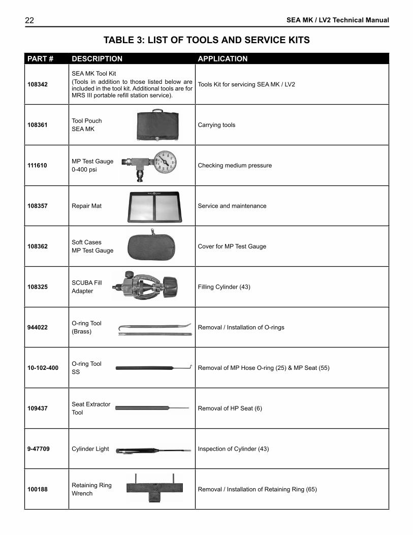
TABLE 3: LIST OF TOOLS AND SERVICE KITS
PART # DESCRIPTION APPLICATION
108342
SEA MK Tool Kit(Tools in addition to those listed below are included in the tool kit. Additional tools are for MRS III portable refill station service).
Tools Kit for servicing SEA MK / LV2
108361 Tool PouchSEA MK
Carrying tools
111610 MP Test Gauge 0-400 psi
Checking medium pressure
108357 Repair Mat Service and maintenance
108362 Soft CasesMP Test Gauge
Cover for MP Test Gauge
108325 SCUBA FillAdapter
Filling Cylinder (43)
944022 O-ring Tool(Brass)
Removal / Installation of O-rings
10-102-400 O-ring Tool SS
Removal of MP Hose O-ring (25) & MP Seat (55)
109437 Seat ExtractorTool
Removal of HP Seat (6)
9-47709 Cylinder Light Inspection of Cylinder (43)
100188 Retaining Ring Wrench
Removal / Installation of Retaining Ring (65)
23
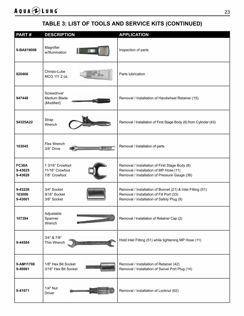
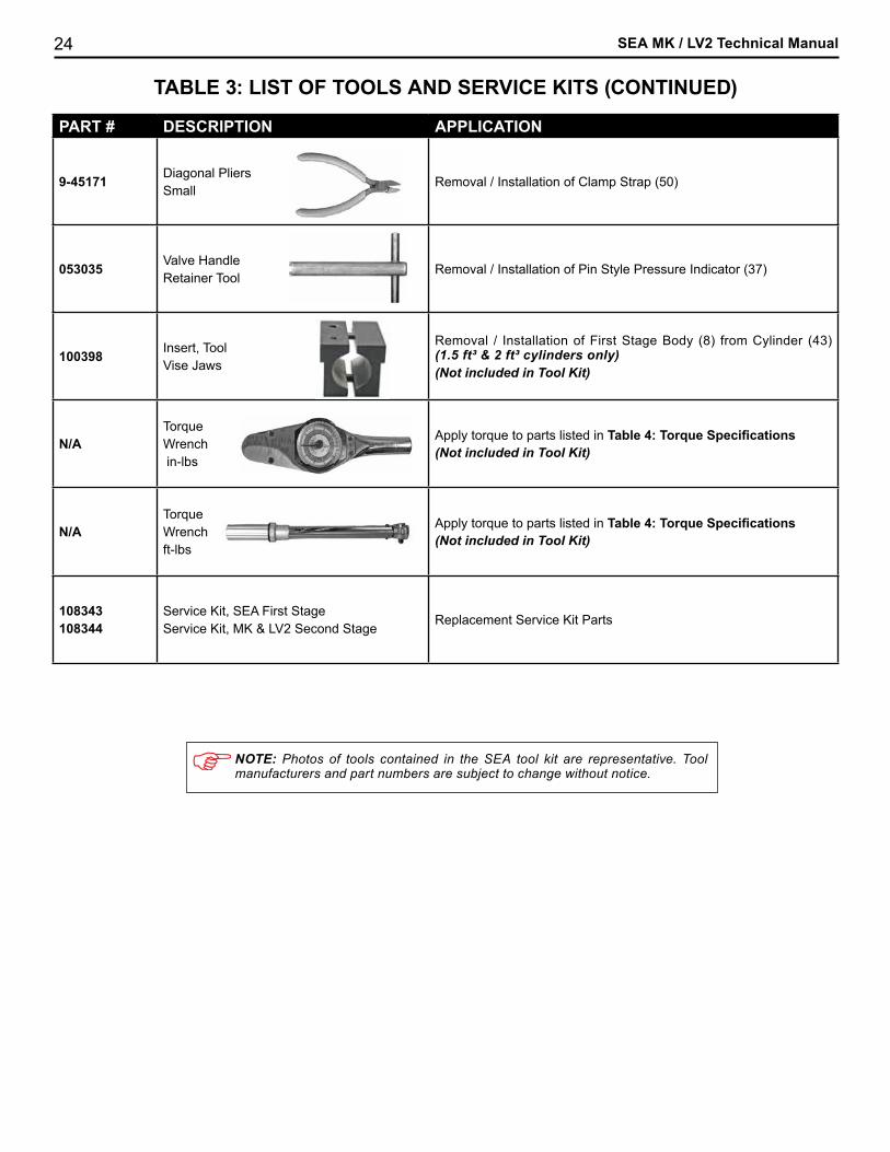
TABLE 3: LIST OF TOOLS AND SERVICE KITS (CONTINUED)
PART # DESCRIPTION APPLICATION
9-BA819008 Magnifierw/Illumination
Inspection of parts
820466 Christo-Lube MCG 111 2 oz.
Parts lubrication
947448ScrewdriverMedium Blade(Modified)
Removal / Installation of Handwheel Retainer (15)
54325A22 Strap Wrench
Removal / Installation of First Stage Body (8) from Cylinder (43)
103045 Flex Wrench 3/8” Drive
Removal / Installation of parts
FC38A9-436259-43628
1 3/16” Crowfoot11/16” Crowfoot7/8” Crowfoot
Removal / Installation of First Stage Body (8)Removal / Installation of MP Hose (11)Removal / Installation of Pressure Gauge (36)
9-432261030069-43001
3/4” Socket9/16” Socket3/8” Socket
Removal / Installation of Bonnet (21) & Inlet Fitting (51)Removal / Installation of Fill Port (33)Removal / Installation of Safety Plug (9)
107394Adjustable SpannerWrench
Removal / Installation of Retainer Cap (2)
9-445843/4” & 7/8"Thin Wrench
Hold Inlet Fitting (51) while tightening MP Hose (11)
9-AM117089-46661
1/8" Hex Bit Socket3/16" Hex Bit Socket
Removal / Installation of Retainer (42)Removal / Installation of Swivel Port Plug (14)
9-41971 1/4" Nut Driver
Removal / Installation of Locknut (62)
SEA MK / LV2 Technical Manual24
PART # DESCRIPTION APPLICATION
9-45171 Diagonal PliersSmall
Removal / Installation of Clamp Strap (50)
053035 Valve Handle Retainer Tool
Removal / Installation of Pin Style Pressure Indicator (37)
100398 Insert, Tool Vise Jaws
Removal / Installation of First Stage Body (8) from Cylinder (43) (1.5 ft³ & 2 ft³ cylinders only)(Not included in Tool Kit)
N/ATorqueWrench in-lbs
Apply torque to parts listed in Table 4: Torque Specifications(Not included in Tool Kit)
N/ATorqueWrenchft-lbs
Apply torque to parts listed in Table 4: Torque Specifications(Not included in Tool Kit)
108343108344
Service Kit, SEA First StageService Kit, MK & LV2 Second Stage
Replacement Service Kit Parts
TABLE 3: LIST OF TOOLS AND SERVICE KITS (CONTINUED)
NOTE: Photos of tools contained in the SEA tool kit are representative. Tool manufacturers and part numbers are subject to change without notice.
25
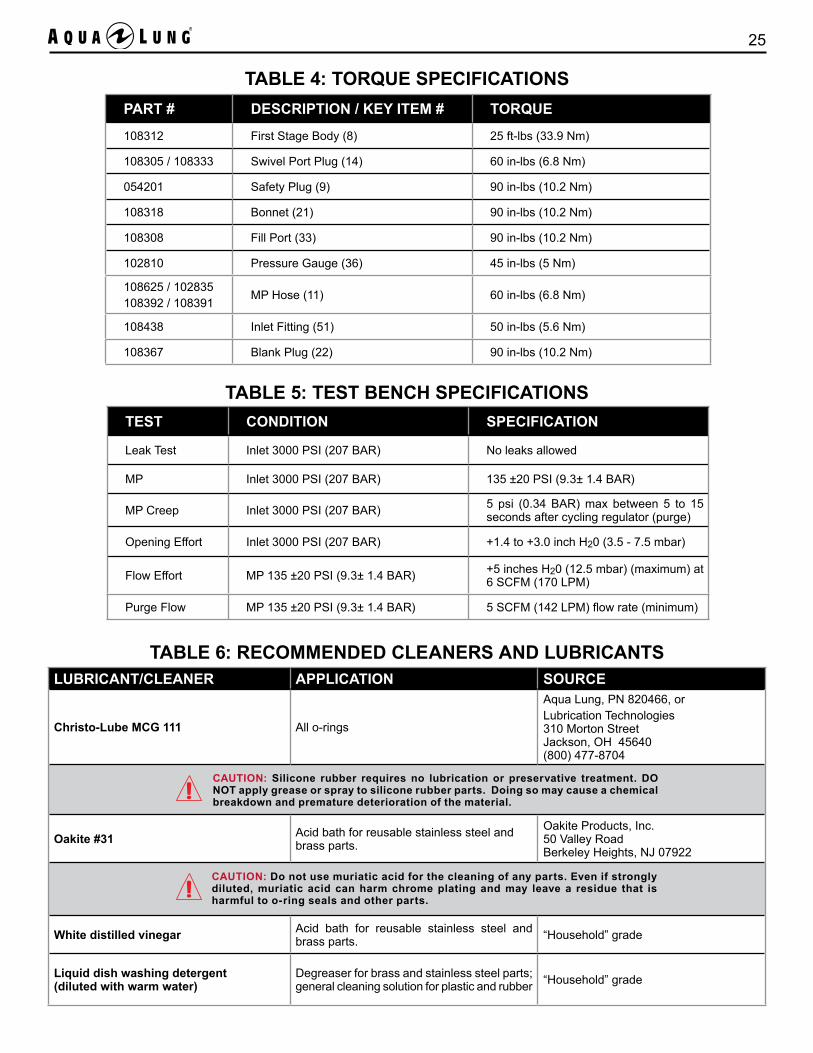
TABLE 4: TORQUE SPECIFICATIONSPART # DESCRIPTION / KEY ITEM # TORQUE
108312 First Stage Body (8) 25 ft-lbs (33.9 Nm)
108305 / 108333 Swivel Port Plug (14) 60 in-lbs (6.8 Nm)
054201 Safety Plug (9) 90 in-lbs (10.2 Nm)
108318 Bonnet (21) 90 in-lbs (10.2 Nm)
108308 Fill Port (33) 90 in-lbs (10.2 Nm)
102810 Pressure Gauge (36) 45 in-lbs (5 Nm)
108625 / 102835108392 / 108391
MP Hose (11) 60 in-lbs (6.8 Nm)
108438 Inlet Fitting (51) 50 in-lbs (5.6 Nm)
108367 Blank Plug (22) 90 in-lbs (10.2 Nm)
TABLE 5: TEST BENCH SPECIFICATIONS TEST CONDITION SPECIFICATION
Leak Test Inlet 3000 PSI (207 BAR) No leaks allowed
MP Inlet 3000 PSI (207 BAR) 135 ±20 PSI (9.3± 1.4 BAR)
MP Creep Inlet 3000 PSI (207 BAR) 5 psi (0.34 BAR) max between 5 to 15 seconds after cycling regulator (purge)
Opening Effort Inlet 3000 PSI (207 BAR) +1.4 to +3.0 inch H20 (3.5 - 7.5 mbar)
Flow Effort MP 135 ±20 PSI (9.3± 1.4 BAR) +5 inches H20 (12.5 mbar) (maximum) at 6 SCFM (170 LPM)
Purge Flow MP 135 ±20 PSI (9.3± 1.4 BAR) 5 SCFM (142 LPM) flow rate (minimum)
TABLE 6: RECOMMENDED CLEANERS AND LUBRICANTSLUBRICANT/CLEANER APPLICATION SOURCE
Christo-Lube MCG 111 All o-rings
Aqua Lung, PN 820466, orLubrication Technologies 310 Morton Street Jackson, OH 45640 (800) 477-8704
Oakite #31 Acid bath for reusable stainless steel and brass parts.
Oakite Products, Inc. 50 Valley Road Berkeley Heights, NJ 07922
White distilled vinegar Acid bath for reusable stainless steel and brass parts. “Household” grade
Liquid dish washing detergent (diluted with warm water)
Degreaser for brass and stainless steel parts; general cleaning solution for plastic and rubber “Household” grade
CAUTION: Silicone rubber requires no lubrication or preservative treatment. DO NOT apply grease or spray to silicone rubber parts. Doing so may cause a chemical breakdown and premature deterioration of the material.
CAUTION: Do not use muriatic acid for the cleaning of any parts. Even if strongly diluted, muriatic acid can harm chrome plating and may leave a residue that is harmful to o-ring seals and other parts.
SEA MK / LV2 Technical Manual26
Cleaning Brass & Stainless Steel Parts1. Pre-clean in warm, soapy water* using a nylon bristle tooth brush.2. Thoroughly clean parts in an ultrasonic cleaner filled with soapy water. If there are stubborn deposits, household white distilled vinegar (acetic acid) in an ultrasonic cleaner will work well. DO NOT place plastic, rubber, silicone or anodized aluminum parts in vinegar.3. Remove parts from the ultrasonic cleaner and rinse with fresh water. If tap water is extremely “hard,” place the parts in a bath of distilled water to prevent any mineral residue. Agitate lightly and allow to soak for 5-10 minutes. Remove and blow dry with clean, low pressure filtered air and inspect closely to ensure proper cleaning and like-new condition.
Cleaning Anodized Aluminum, Plastic & Rubber PartsAnodized aluminum parts and parts made of plastic, rubber or silicone such as box bottoms, box tops, dust caps, diaphragms, etc., may be soaked and cleaned in a solution of warm water mixed with mild dish soap. Use only a soft nylon toothbrush to scrub away any deposits. Rinse in fresh water and thoroughly blow dry, using low pressure filtered air.
Cleaning Hoses1. Hose fittings: Ultrasonically clean with soapy water*; vinegar OK on tough corrosion – (only hose ends).2. Run soapy water through hose if needed.3. Thoroughly rinse with fresh water– (hang with hose ends down).4. Blow out hose before installing.
Lubrication and DressingAll o-rings should be lubricated with Christo-Lube® MCG 111. Dress the o-rings with a very light film of lubricant and remove any visible excess by running the o-ring between thumb and forefinger. Avoid applying excessive amounts of Christo-Lube® MCG 111, as this will attract particulate matter that may cause damage to the o-ring.
*Soapy water is defined as “household” grade liquid dishwashing detergent diluted in warm water.
PROCEDURE A: CLEANING AND LUBRICATING
CAUTION: Do not place plastic, rubber, silicone or anodized aluminum parts in acid solutions. Doing so may alter the physical properties of the component, causing it to prematurely degrade and/or break.
CAUTION: Silicone grease and sprays must be strictly avoided, since silicone does not provide adequate lubricity in extreme weather conditions.
27
13
12
3
4
56
7
15
2426
10
353432
3231
3645 in-lbs(5 Nm)
33
90 in-lbs(10.2 Nm)
2829
2725
2321
90 in-lbs(10.2 Nm) 20
161718
90 in-lbs(10.2 Nm)
9
60 in-lbs(6.8 Nm)
14
1112
19
30
32
43
90 in-lbs(10.2 Nm)
22
25 ft-lbs(33.9 Nm)
8
38 3439
4041
4232
37
23
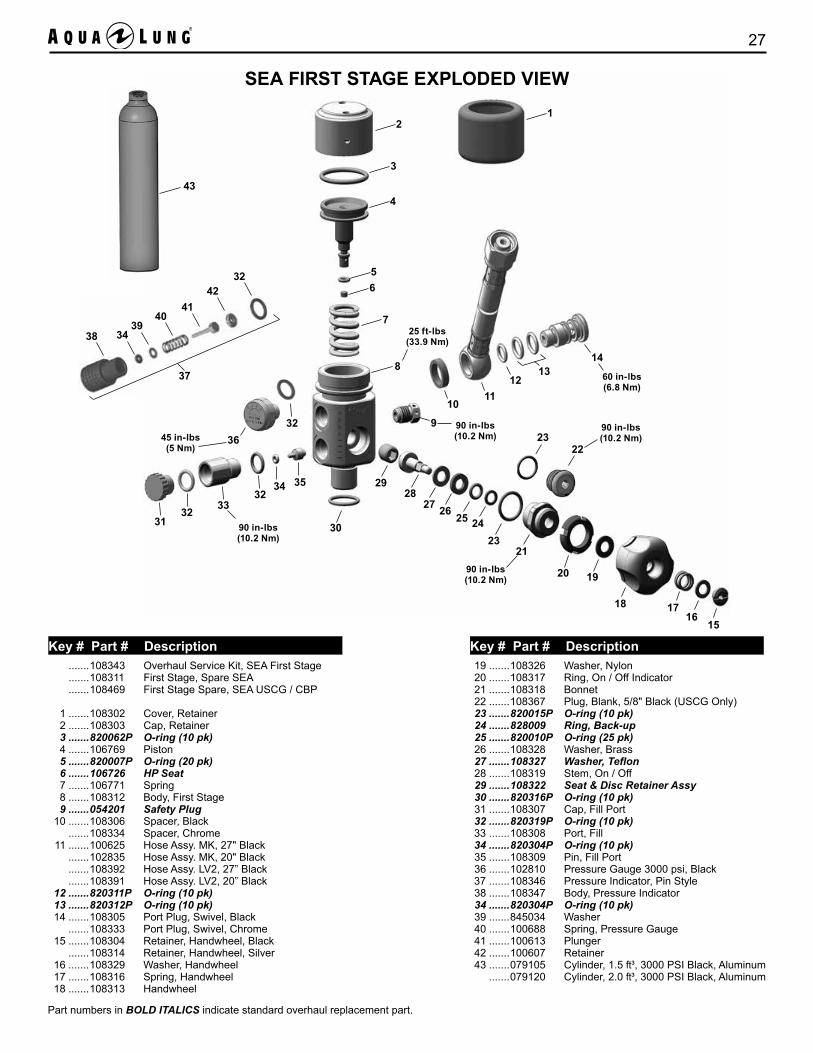
SEA FIRST STAGE EXPLODED VIEW
19 .......108326 Washer, Nylon 20 .......108317 Ring, On / Off Indicator 21 .......108318 Bonnet 22 .......108367 Plug, Blank, 5/8" Black (USCG Only) 23 .......820015P O-ring (10 pk) 24 .......828009 Ring, Back-up 25 .......820010P O-ring (25 pk) 26 .......108328 Washer, Brass 27 .......108327 Washer,Teflon 28 .......108319 Stem, On / Off 29 .......108322 Seat & Disc Retainer Assy 30 .......820316P O-ring (10 pk) 31 .......108307 Cap, Fill Port 32 .......820319P O-ring (10 pk) 33 .......108308 Port, Fill 34 .......820304P O-ring (10 pk) 35 .......108309 Pin, Fill Port 36 .......102810 Pressure Gauge 3000 psi, Black 37 .......108346 Pressure Indicator, Pin Style 38 .......108347 Body, Pressure Indicator 34 .......820304P O-ring (10 pk) 39 .......845034 Washer 40 .......100688 Spring, Pressure Gauge 41 .......100613 Plunger 42 .......100607 Retainer 43 .......079105 Cylinder, 1.5 ft³, 3000 PSI Black, Aluminum .......079120 Cylinder, 2.0 ft³, 3000 PSI Black, Aluminum
.......108343 Overhaul Service Kit, SEA First Stage .......108311 First Stage, Spare SEA .......108469 First Stage Spare, SEA USCG / CBP
1 .......108302 Cover, Retainer 2 .......108303 Cap, Retainer 3 .......820062P O-ring (10 pk) 4 .......106769 Piston 5 .......820007P O-ring (20 pk) 6 .......106726 HP Seat 7 .......106771 Spring 8 .......108312 Body, First Stage 9 .......054201 Safety Plug 10 .......108306 Spacer, Black .......108334 Spacer, Chrome 11 .......100625 Hose Assy. MK, 27" Black .......102835 Hose Assy. MK, 20" Black .......108392 Hose Assy. LV2, 27” Black .......108391 Hose Assy. LV2, 20” Black 12 .......820311P O-ring (10 pk) 13 .......820312P O-ring (10 pk) 14 .......108305 Port Plug, Swivel, Black .......108333 Port Plug, Swivel, Chrome 15 .......108304 Retainer, Handwheel, Black .......108314 Retainer, Handwheel, Silver 16 .......108329 Washer, Handwheel 17 .......108316 Spring, Handwheel 18 .......108313 Handwheel
Part numbers in BOLD ITALICS indicate standard overhaul replacement part.
Key # Part # Description Key # Part # Description
SEA MK / LV2 Technical Manual28
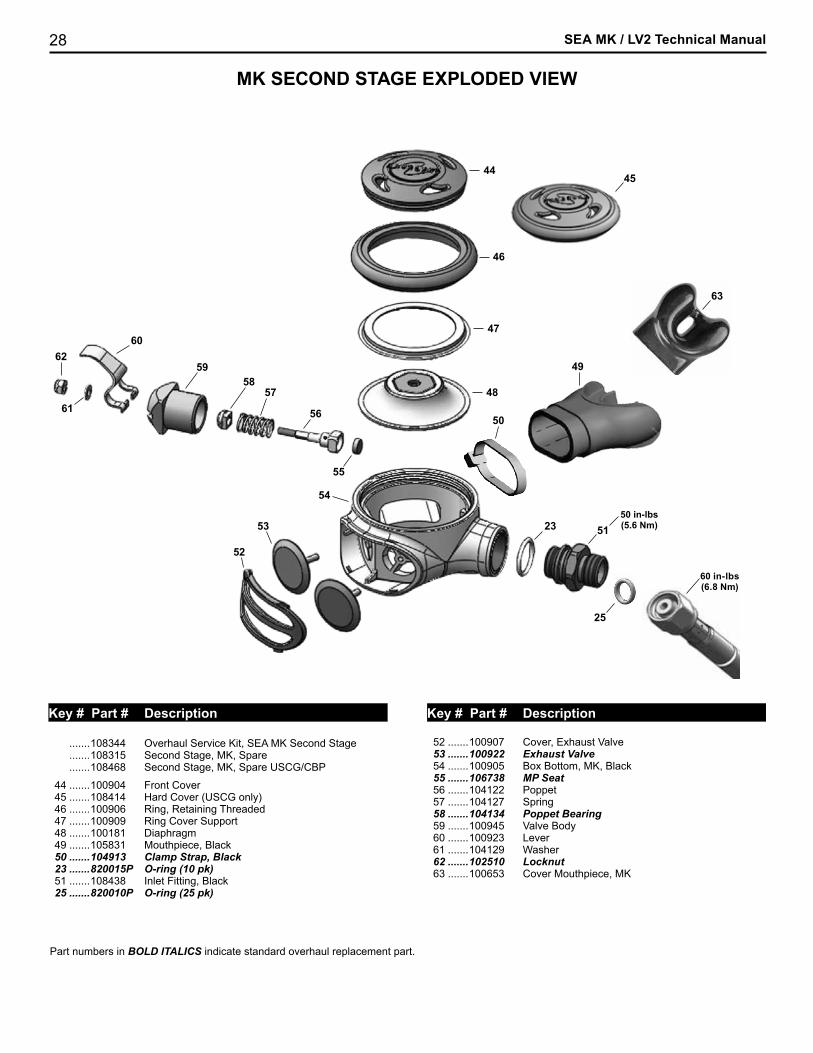
MK SECOND STAGE EXPLODED VIEW
Key # Part # Description Key # Part # Description
.......108344 Overhaul Service Kit, SEA MK Second Stage .......108315 Second Stage, MK, Spare .......108468 Second Stage, MK, Spare USCG/CBP
44 .......100904 Front Cover 45 .......108414 Hard Cover (USCG only) 46 .......100906 Ring, Retaining Threaded 47 .......100909 Ring Cover Support 48 .......100181 Diaphragm 49 .......105831 Mouthpiece, Black 50 .......104913 Clamp Strap, Black 23 .......820015P O-ring (10 pk) 51 .......108438 Inlet Fitting, Black 25 .......820010P O-ring (25 pk)
52 .......100907 Cover, Exhaust Valve 53 .......100922 Exhaust Valve 54 .......100905 Box Bottom, MK, Black 55 .......106738 MP Seat 56 .......104122 Poppet 57 .......104127 Spring 58 .......104134 Poppet Bearing 59 .......100945 Valve Body 60 .......100923 Lever 61 .......104129 Washer 62 .......102510 Locknut 63 .......100653 Cover Mouthpiece, MK
Part numbers in BOLD ITALICS indicate standard overhaul replacement part.
53
5758
59
44
55
54
50
52
49
61
6260
56
25
60 in-lbs(6.8 Nm)
23
45
46
47
48
5150 in-lbs(5.6 Nm)
63
29
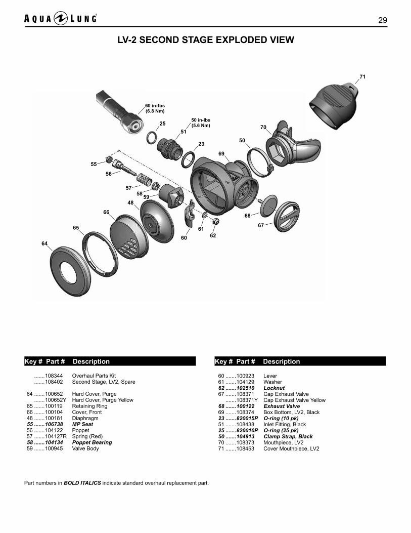
Part numbers in BOLD ITALICS indicate standard overhaul replacement part.
.......108344 Overhaul Parts Kit .......108402 Second Stage, LV2, Spare 64 .......100652 Hard Cover, Purge .......100652Y Hard Cover, Purge Yellow 65 .......100119 Retaining Ring 66 .......100104 Cover, Front 48 .......100181 Diaphragm 55 .......106738 MP Seat 56 .......104122 Poppet 57 .......104127R Spring (Red) 58 .......104134 Poppet Bearing 59 .......100945 Valve Body
60 .......100923 Lever 61 .......104129 Washer 62 .......102510 Locknut 67 .......108371 Cap Exhaust Valve .......108371Y Cap Exhaust Valve Yellow 68 .......100122 Exhaust Valve 69 .......108374 Box Bottom, LV2, Black 23 .......820015P O-ring (10 pk) 51 .......108438 Inlet Fitting, Black 25 .......820010P O-ring (25 pk) 50 .......104913 Clamp Strap, Black 70 .......108373 Mouthpiece, LV2 71 .......108453 Cover Mouthpiece, LV2
LV-2 SECOND STAGE EXPLODED VIEW
64
65
66
55
56
575859
68
67
50
70
48
25
60 in-lbs(6.8 Nm)
6061
62
23
69
51
50 in-lbs(5.6 Nm)
71
Key # Part # Description Key # Part # Description
SEA MK / LV2 Technical Manual30
MAINTENANCE NOTES
31
MAINTENANCE NOTES
2340 Cousteau Court • Vista, CA 92081Phone (760) 597-5000 • Fax (760) 597-4900www.aqualung.com/militaryandprofessional
Blue = Pantone 2728C
Primary/Preferred Branding
Secondary Branding
Tertiary Branding
©2017 Aqua Lung International
Survival Egress Air (SEA MK / LV2)
Technical Manual