Embed Size (px)
Citation preview

No. L C Y – 0 2 0 6 3 A DATE J u n e . 6 . 2002
TECHNICAL LITERATURE
FOR
TFT - LCD module
MODEL No. LQ065Y5DG01
The technica l litera ture is subject to change without not ice. So , please contact Sharp or it s representa t ive before designing your product based on th is lit era ture.
SHARP CORPORATION
ENGINEERING DEPARTMENT. Ⅱ
MOBILE LCD DESINE CENTER
MOBILE LIQUID CRYSTAL DISPLAY GROUP

RECORDS OF REVISION
MODEL No:LQ065Y5DG01
SPEC No. Date NO. PAGE SUMMARY NOTE
LCY-02063 2002. 6. 6 - - 1st Issue
LCY-02063A 2002.7.5 10 Table7-4 VCC=13.7V→VCC =-14.1V
14 11-4) B) CN1→CN3

LCY02063-1
NOTICE This publica t ion is the propr ietary of SHARP and is copyr ighted, with a ll r ights reserved. Under the copyr ight laws, no par t of th is publica t ion may be reproduced or t ransmit ted in any form or by any means, elect ron ic or mechanica l for any purpose, in whole or in par t , without the express writ ten permission of SHARP. Express writ ten permission is a lso required before any use of th is publicat ion may be made by a th ird par ty. The applica t ion circuit examples in th is publica t ion are provided to expla in the representa t ive applica t ions of SHARP's devices and are not in tended to guarantee any circu it design or permit any indust r ia l proper ty r ight or other r ights to be executed. SHARP takes no responsibility for any problems rela ted to any indust r ia l proper ty r ight or a th ird par ty result ing from the use of SHARP's devices, except for those result ing direct ly from device manufactur ing processes. In the absence of confirmat ion by device specifica t ion sheets, SHARP takes no responsibility for any defects tha t occur in equipment using any of SHARP's devices, shown in ca ta logs, da ta books, etc. Contact SHARP in order to obta in the la test device specifica t ion sheets before using any SHARP's device. SHARP reserves the r ight to make changes in the specifica tions, character ist ics, data , mater ia ls, st ructures and other contents descr ibed herein a t any t ime without not ice in order to improve design or reliability. Contact SHARP in order to obta in the la test specifica t ion sheets before using any SHARP's device. Manufactur ing loca t ions a re a lso subject to change without not ice. Observe the following poin ts when using any device in th is publica t ion . SHARP takes no responsibility for damage caused by improper use of the devices. The devices in th is publica t ion are designed for use in genera l elect ronic equipment designs , such as: ・Car Navigat ion system ・Automot ive auxilia ry informat ion display ・Automot ive audio visua l equipment The appropr ia te design measures should be taken to ensure reliability and safety when SHARP's devices a re used for equipment such as: ・Transpor ta t ion cont rol and safety equipment(i.e.,a ircraft ,t ra ins,automobiles,etc.) ・Traffic signals ・Gas leakage sensor breakers ・Alarm equipment ・Various safety devices etc. SHARP's devices sha ll not be used for equipment tha t requires ext remely high level of reliability, such as: ・Military and space applica t ions ・Nuclear power cont rol equipment ・Medical equipment for life suppor t Contact a SHARP represen ta t ive, in advance, when in tending to use SHARP's devices for any "specific" applicat ions other than those recommended by SHARP. Contact and consult with a SHARP representa t ive if there a re any quest ions about the contents of th is publica t ion.

LCY02063-2 1 . A p p l i c a t i o n The SHARP Color TFT-LCD module is an act ive matr ix LCD (Liquid Crysta l Display) produced by making the most of Sharp's exper t ise in liquid-crysta l and semiconductor technologies. The act ive device is amorphous silicon TFT (Thin Film Transistor). Module geometry(Mechanica l specifica t ion) : Table 4-1 2 . S u m m a r y a n d F e a t u r e s ・It cor responds to a wide screen by using the panel of aspect ra t io 15:9. ・The 6.5 screen produces a h igh resolu t ion image tha t is composed of 384,000 pixels elements in a st r ipe arrangement . ・Graphics and texts can be displayed on a 800×RGB×480 dots panel with 262,144 colors by supplying 18 bit da ta signals(6 bit /color ). ・By adopt ing an act ive matr ix dr ive, a picture with h igh cont rast is rea lized. ・Reduced reflect ion as a result of low reflect ion black matr ix and an ant iglare (AG) pola r izer being adopted. ・Wide viewing angle technology is employed. (The most su itable viewing angle is in the 6 o'clock direct ion .) ・By COG method, rea lized a slim, lightweight , and compact module. ・Through the use of TN-normally white mode, an image with h igh ly na tural color reproduct ion is rea lized. ・An inver ted video display in the ver t ica l and hor izonta l direct ions is possible. ・The backlight is excellent of br ightness r ising character ist ics a t low temperature in considera t ion of automot ive applica t ion . 3 . C o n s t r u c t i o n a n d O u t l i n e ・ The const ruct ion form figure : See F ig.1 ・ The module consists of a TFT-LCD panel, dr ivers, FPC, backlight , frame, front sh ielding cases. 4 . M e c h a n i c a l s p e c i f i c a t i o n s Table 4-1
Parameter Specifica t ions Units Remarks Screen size (Diagonal) 16 [6.5”] cm Act ive area 144.0(H)×78.24(V) mm Display format 800(H )×RGB×480(V) dots Dot pitch 0.06(H)×0.163(V) mm P ixel configura t ion R,G,B St r ipe configura t ion Out line dimension 157.2(W)×89.7 (H )×8.4(D) mm 【Note4-1】 Mass 185(MAX) g
【Note 4-1】 Excluding prot rusions. Typica l va lues a re given . For deta iled measurements and tolerances, please refer to Fig. 1.

LCY02063-3 5 . I n p u t t e r m i n a l 5-1)TFT-LCD panel dr iving par t Table 5-1 terminal: CNIN1
Pin No. Symbol Descr ipt ion Remarks 1 COM Common elect rode dr iving signal1 2 COM Common elect rode dr iving signal1 3 CS Common elect rode dr iving signal2 4 CS Common elect rode dr iving signal2 5 VSHA Power supply for source dr iver (Analog). 6 VSHA Power supply for source dr iver (Ana log). 7 PS Test terminal for source dr iver(please connect to GND) 8 R0 RED da ta signa l(LSB) 9 R1 RED da ta signa l
10 R2 RED da ta signa l 11 R3 RED da ta signa l 12 R4 RED da ta signa l 13 R5 RED da ta signa l(MSB) 14 GND Ground 15 G0 GREEN data signa l(LSB) 16 G1 GREEN da ta signa l 17 G2 GREEN da ta signa l 18 G3 GREEN da ta signa l 19 G4 GREEN da ta signa l 20 G5 GREEN data signa l(MSB) 21 GND Ground 22 SPOI Star t signal1 for source dr iver . 【Note5-1】 23 V10 The Power supply for gray image 24 V9 The Power supply for gray image 25 V7 The Power supply for gray image 26 V5 The Power supply for gray image 27 V3 The Power supply for gray image 28 V0 The Power supply for gray image 29 GND Ground 30 DCLK Clock signal for source dr iver. 31 GND Ground 32 LS Data t ransfer signal for source dr iver . 33 VSHD Power supply for source dr iver . (Digita l) 34 VSHD Power supply for source dr iver . (Digita l) 35 GND Ground 36 B0 BLUE da ta signa l(LSB) 37 B1 BLUE da ta signa l 38 B2 BLUE da ta signa l 39 B3 BLUE da ta signa l 40 B4 BLUE da ta signa l 41 B5 BLUE da ta signa l(MSB) 42 GND Ground 43 LBR Select ion for hor izonta l scanning direct ion 【Note5-1】 44 GND Ground 45 SPIO Star t signal2 for source dr iver . 【Note5-1】

LCY02063-4
Table5-2 terminal: CNIN2 Pin No. Symbol Descr ipt ion Remarks
1 COM Common elect rode dr iving signal1 2 COM Common elect rode dr iving signal1 3 CS Common elect rode dr iving signal2 4 CS Common elect rode dr iving signal2 5 OPEN Non connect ion (Don’t connect) 6 VDD Power supply for TFT’s tu rn on voltage. 7 VLS(G) Power supply for input level sh ifter 8 MODE2 Output mode changing termina l 2 【Note5-2】 9 MODE1 Output mode changing termina l 1 【Note5-2】
10 R/L Select ion for ver t ica l scanning direct ion 【Note5-1】 11 GND Ground 12 GND Ground 13 CLS Clock signal for ga te dr iver 14 SPS Star t signa l for ga te dr iver 15 OPEN Non connect ion (Don ’t connect) 16 VCC Power supply for logic circu it in ga te dr iver (High level). 17 OPEN Non connect ion (Don’t connect) 18 VEE Power supply for TFT’s cu t off voltage 19 OPEN Non connect ion (Don’t connect) 20 VSS Power supply for logic circuit in gate dr iver (Low level).
【Note 5-1】The cont rol of scanning direct ion
Table5-3 Mode R/L LBR SPOI SPIO
Normal mode Lo H i In pu t Ou tpu t Right /Left reverse mode Lo Lo Ou tpu t In pu t Up/Down reverse mode H i H i In pu t Ou tpu t Right /Left & Up/Down reverse mode H i Lo Ou tpu t In pu t
【caut ion】 Lo=GND , Hi=VSHD,VLS(G) 【Note 5-2】Refer to “Notes a t the t ime of a power supply turn in g on ” in clause 7-1 for the star t -u p
and the standing lower ing of the power supply. The ga te dr iver is selected to output by set t ing mode 1 and mode 2..
Table5-4 MODE1 MODE2
H i H i Normal mode Lo H i Don 't use th is mode. H i Lo Skip 2 pulse mode (See Fig.5-1) Lo Lo The mode which fixes a ll the output on the VEE level
【caut ion】 Lo=GND , Hi=VLS(G)

LCY02063-5
F ig5-1. Gate output t iming
5-2)Backlight fluorescent tube dr iving par t Table 5-5 terminal: CN3
No. Symbol funct ion Remarks 1 VL1 input termina l(Hi voltage side) 2 VL2 input terminal (Low voltage side) 【Note5-3】
【Note 5-3】Connect the low voltage side of the DC/AC inver ter used to dr ive the fluorescent tube to GND of the inver ter circuit .
CLS
SP S
Nor m a l m ode(1pu lse m ode)
Skip 2pu lse m ode
DH 1(DH480)
DH 2(DH479)
Dummy
DH 1(DH480)
DH 2(DH479)
Dummy
Dummy
Dummy
Dummy
Dummy
Dummy
Dummy
1 2 3 4 5 6 7 8 9

LCY02063-6 6 . A b s o l u t e m a x i m u m r a t i n g s Table 6-1 GND=0V
Parameter Symbol MIN MAX Unit Note Analog voltage VSHA -0.3 +6.0 V Ta=25℃ Power supply
(source driver ) Digita l voltage VSHD -0.3 +6.0 V 〃 VDD -0.3 +35.0 V 〃
VLS(G) -0.3 +6.0 V 〃 VCC-VSS -0.3 +6.0 V 〃 VEE-VSS -0.3 +35.0 V 〃
Power supply (gate driver )
VDD-VE E (VSS)
-0.3 +35.0 V 〃
Digita l input signal VID(S) -0.3 VSHD+0.3 V 〃【Note 6-1】 Input signal voltage (source dr iver) Analog input signal VIA -0.3 VSHA+0.3 V 〃【Note 6-2】 Input signal voltage (gate dr iver) VID(G) -0.3 VLS(G)+0.3 V 〃【Note 6-3】 Common electrode dr iving signal COM -4 +6 V 〃 Storage temperature Tstg -40 +85 ℃ 【Note 6-4,5】 Operat ing temperature (panel surface) Topr1 -30 +85 ℃ 【Note 6-5,6】 Oper a t in g t em per a t u r e(Am bien t t em per a t u r e)
Topr2 -30 +65 ℃ 【Note 6-7】
【Note 6-1】 SPOI , SPIO , R0~R5 , G0~G5 , B0~B5 ,LS , DCLK , LBR 【Note 6-2】 V0 , V3 , V5 , V7 , V9 , V10 【Note 6-3】 MODE1 , MODE2 , R/L , SPS , CLS
【Note 6-4】 This ra t ing applies to a ll par t s of the module and should not be exceeded. 【Note 6-5】 Maximum wet-bulb tempera ture is 58℃.Condensa t ion of dew must be avoided as
elect r ica l current leaks will occur , causing a degrada t ion of per formance specificat ions.
【Note 6-6】 The opera t ing tempera ture only guarantees opera t ion of the circu it . For contrast , speed response, and other factors rela ted to display quality, determine opera t ing tempera ture using the formula Ta=+25℃
【Note 6-7】 Ambient tempera ture when the backlight is lit (reference va lue).

LCY02063-7 7 . E l e c t r i c a l c h a r a c t e r i s t i c s 7-1)TFT-LCD panel dr iving sect ion Table 7-1 GND=0V,Ta=25℃
Parameter Symbol MIN TYP MAX Unit Remarks Ana log volt age VSHA +4.5 +5.0 +5.5 V Power supply
(source dr iver) Digita l voltage VSHD +3.0 +3.3 +3.6 V H igh level VDD +14.8 +15.0 +15.2 V
AC VEE AC - COM AC - Vp-p 【Note7-1】 TFT dr iving circuit
Low level DC VEE DC -11.8 -12.0 -12.2 V
H igh level VCC VSS+VLS(G)-0.1
VSS+ VLS(G)
VSS+ VLS(G)+0.1
V 【Note7-2】 Logic circuit Low level VSS -17.0 -17.4 -17.8 V
Power supply (ga te dr iver )
Shift register VLS(G) +3.0 +3.3 +3.6 Power supply (gray image) V0~V10 0 - VSHA V 【Note7-3】
H igh level VIHS 0.8×VSHD - VSHD V Inpu t signa l voltage for source dr iver Low level VILS GND - 0.2×VSHD V
【Note7-4】
H igh level IIH S1 - - 10 μA 【Note7-5】 IIH S2 400 μA 【Note7-6】
Input signa l cur ren t for source dr iver
Low level IILS - - 10 μA 【Note7-4】 H igh level VIHG 0.8×VLS(G) - VLS(G) V Inpu t signa l voltage
for ga te dr iver Low level VILG GND - 0.2×VLS(G) V High level IIH G - - 1.0 μA Input signa l cur ren t
for ga te dr iver Low level IILG - - 1.0 μA
【Note7-7】
AC component COMAC - ±3.4 ±3.6 Vp-p Common electrode dr iving signa l DC componen t COMDC 0 - +3.0 V
【Note7-8】
・Notes a t the t ime of a power supply turn in g on
Please turn on and tu rn off power supply in simultaneous or the following order . <Turn on> VSHD , VSHA ,VLS(G) Ë VSS , VCC Ë VEE Ë Logic signal Ë VDD <Turn off> VDD Ë Logic signal Ë VEE Ë VSS,VCC Ë VSHD , VSHA ,VLS(G)
*Condit ion: VSS < VCC At the MODE1 and MODE2 signa ls, please hold Low voltage for more than 2 ver t ica l synchronous term after Low voltage is input a t the t ime of a power supply turning on and VCC r ises completely. Then , please hold High voltage unt il the power supply is tu rned off. 【Note 7-1】 P lease car ry out polar reversa l in the same amplitude and the same phase as VCOM. 【Note 7-2】 Condit ion: 3.0V ≦ VCC-VSS ≦ 3.6V 【Note 7-3】It is a standard power supply for gray sca le. Whenever the polar ity of common elect rode dr ive signa l (COM) is changed, please a lso change th is standard voltage. V0 (black) power supply becomes the reverse character ist ic of COM, and V10 (white) becomes the same polar ity as COM.
Please sh ift the center va lue of each power supply amplitude to the plus(+) direct ion according to the character ist ic of liquid crysta l as it will go to white side like V3, V5, V7, V9, V10, if the cen ter va lue of each power supply amplitude is based on the cen ter va lue of V0 (black).
After DC adjustment of COM signal is adjusted in case of the V0 gray sca le display, please adjust th is amount of shift s so tha t a flicker does not occur in the power supply display of each gray sca le. 【Note 7-4】 Apply to the terminal SPOI, R0-R5, G0-G5, B0-B5, LS, DCLK, LBR, and SPIO 【Note 7-5】 Apply to the terminal SPOI, R0-R5, G0-G5, B0-B5, LS, DCLK, LBR, and SPIO 【Note 7-6】 Apply to the terminal PS 【Note 7-7】 Apply to the termina l MODE1,MODE2, R/L, SPS, and CLS

LCY02063-8 【Note 7-8】 P lease switch polar ity of amplitude COMAC by center va lue of amplitude tha t is COMDC for every one level scan and every one ver t ica l scan . Moreover , please adjust COMDC so tha t cont rast becomes the maximum and a flicker becomes the minimum for every module. 7-2)Backlight dr iving sect ion Table 7-2
Parameter Symbol MIN TYP MAX Unit Remarks lamp voltage VL7 640 710 780 Vrms IL=4.5mArms
IL 4.0 4.5 5.5 mArms Ordinary sta te lamp cur ren t ILB - - 9.0 mArms At the boost【Note 7-9】
lamp frequency fL 30 - 70 kHz Discharge pipe electr ic power
WL - 3.2 - W When ligh t ing up in the standard
kick-off volt age VS - - 1750 Vrms Ta=+25℃ - - 1800 Vrms Ta=-30℃
Inver t er : HIU-288 [HARISON TOSHIBA LIGHTING co. ,ltd] (Outpu t capasitor : 22pF , fr equency : 49kHz)
【Caut ion】 P lease use the inver ter which has the one of the sine wave. With regards to the inver ter ,it should be nega t ive/posit ive wave symmetry and the spike wave should not be occur red.
【Note 7-9】 With in 5 minutes. The tempera ture is less than 0℃.

LCY02063-9 7-3) Timing character ist ics Timing diagrams of input signa l a re shown in F ig2-1,F ig2-2 Table 7-3 VSHA=+5.0V , VSHD・VLS(G)=3.3V , GND=0V , Ta=25℃
Parameter Symbol MIN TYP MAX Unit Remarks Opera t ing Clock frequency fck - 33.2 34.6 MHz High level clock width Tcwh 12 - - n s Low level clock width Tcwl 13 - - n s Clock rise t ime Tcr - - 4 n s Clock fall t ime Tcf - - 4 n s
DCLK
Star t pulse frequency fsp - 31.5 31.8 kHz Star t pulse set up t ime Tsusp 4 - - n s Star t pulse hold t ime Thsp 0 - - n s Stapt pulse width Twsp 1/fck 1/fck 1.5/fck n s
SPOI SPIO
【Note7-10】
LS pulse frequency flp - fsp - kHz LS pulse set up t ime (CLS) Tsulp 5.0 - - μs LS pu lse set u p t im e (SP OI,S P I O) Tsulpsp 1/fck - - n s LS pulse hold t ime (DCLK) Thlpck 20 - - n s High level LS pulse wide Twlp 1/fck - - n s
LS
Data set up t ime Tsud 15 - - n s
SOURCE
Data hold t ime Thd 10 - - n s R0~R5 , G0~G5 , B0~B5
Opera t ing Clock frequency fcls - fsp - kHz Clock pulse with Twl 5.5 - (1/fcls)-53 μs Clock rise t ime Trcl - - 1/fck n s Clock fall t ime Tfcl - - 1/fck n s
CLS
Star t pulse frequency fsps - 60 65.0 H z Star t pulse set up t ime Tsusps 100 - - n s Star t pulse hold t ime Thsps 300 - - n s Start pulse r ise t ime Trsps - - 100 n s
GATE
Star t pulse fa ll t ime Tfsps - - 100 n s
SPS
COM signal set up t ime Tsucom 3 - - μs COM signal hold t ime Thcom 0 - - μs COM signal r ise t ime Trcom - - 2 μs COM signal fa ll t ime Tfcom - - 2 μs
COM
V0~V10 signal set up t ime Tsuv0 3 - - μs V0~V10 signal hold t ime Th v0 0 - - μs V0~V10 signal r ise t ime Trv0 - - 2 μs V0~V10 signal fa ll t ime Tfv0 - - 2 μs
V0,V3,V5 V7,V9,V10
【Note7-10】 The r ising pulse in DCLK is existed only 1 t ime dur ing Hi per iod (Twsp) on star t pulse.

LCY02063-10 7-4) Current dissipat ions t able7-4 Ta=25℃
Parameter Symbol Condit ions MIN TYP MAX Un it Analog ISHA VSHA=+5.0V - 35 85 m A Current for
source driver Digita l ISHD VSHD =+3.3V - 6 16 m A Hi IDD VDD =+15.0V - 0.12 0.32 m A Lo IEE VEE=-12.0±3.4V - -0.03 -0.08 m A Logic Hi ICC VCC =-14.1V - 0.03 0.08 m A Logic Lo ISS VSS =-17.4V - -0.07 -0.18 m A
Current for gate driver
Shift register ILS(G) VLS(G)=+3.3V - 6 16 m A *Max current situa t ion: Ver t ica l st r ipe pa t tern a lterna t ing 21 gray sca le (GS21) with 42 gray sca le (GS42) every 1 dot . Timing:fck=32MHz , fsp=30.3kHz , fsps=57.7Hz
In case of using exclusive control-IC (LZ9J G17). 7-5) Input Data Signa ls and Display Posit ion on the screen Display posit ion of input da ta (H,V)
D1 ,DH 1
D1 ,DH 2
D1 ,DH 3
D1,DH 480
D2 ,DH 1
D800,DH 48
0
D800,DH 1
D2 ,DH 2
R
D3,DH 1
G B
UP

LCY02063-11 8 . I n p u t S i g n a l s , B a s i c D i s p l a y C o l o r a n d G r a y S c a l e o f E a c h C o l o r
Colors & Da ta signa l 0 :Low level voltage 1 :High level voltage Gray scale Gray Sca le R0 R1 R2 R3 R4 R5 G0 G1 G2 G3 G4 G5 B0 B1 B2 B3 B4 B5
Black - 0 0 0 0 0 0 0 0 0 0 0 0 0 0 0 0 0 0 Blue - 0 0 0 0 0 0 0 0 0 0 0 0 1 1 1 1 1 1
Green - 0 0 0 0 0 0 1 1 1 1 1 1 0 0 0 0 0 0 Cya n - 0 0 0 0 0 0 1 1 1 1 1 1 1 1 1 1 1 1 Red - 1 1 1 1 1 1 0 0 0 0 0 0 0 0 0 0 0 0
Magenta - 1 1 1 1 1 1 0 0 0 0 0 0 1 1 1 1 1 1 Yellow - 1 1 1 1 1 1 1 1 1 1 1 1 0 0 0 0 0 0
Basic color
White - 1 1 1 1 1 1 1 1 1 1 1 1 1 1 1 1 1 1 Black GS0 0 0 0 0 0 0 0 0 0 0 0 0 0 0 0 0 0 0 Ò GS1 1 0 0 0 0 0 0 0 0 0 0 0 0 0 0 0 0 0
Darker GS2 0 1 0 0 0 0 0 0 0 0 0 0 0 0 0 0 0 0 Ò ‚ ‚ ‚ ‚ Ú ‚ ‚ ‚ ‚
Br ighter GS61 1 0 1 1 1 1 0 0 0 0 0 0 0 0 0 0 0 0 Ú GS62 0 1 1 1 1 1 0 0 0 0 0 0 0 0 0 0 0 0
Gray Scale of red
Red GS63 1 1 1 1 1 1 0 0 0 0 0 0 0 0 0 0 0 0 Black GS0 0 0 0 0 0 0 0 0 0 0 0 0 0 0 0 0 0 0 Ò GS1 0 0 0 0 0 0 1 0 0 0 0 0 0 0 0 0 0 0
Darker GS2 0 0 0 0 0 0 0 1 0 0 0 0 0 0 0 0 0 0 Ò ‚ ‚ ‚ ‚ Ú ‚ ‚ ‚ ‚
Br ighter GS61 0 0 0 0 0 0 1 0 1 1 1 1 0 0 0 0 0 0 Ú GS62 0 0 0 0 0 0 0 1 1 1 1 1 0 0 0 0 0 0
Gray Scale of green
Green GS63 0 0 0 0 0 0 1 1 1 1 1 1 0 0 0 0 0 0 Black GS0 0 0 0 0 0 0 0 0 0 0 0 0 0 0 0 0 0 0 Ò GS1 0 0 0 0 0 0 0 0 0 0 0 0 1 0 0 0 0 0
Darker GS2 0 0 0 0 0 0 0 0 0 0 0 0 0 1 0 0 0 0 Ò ‚ ‚ ‚ ‚ Ú ‚ ‚ ‚ ‚
Br ighter GS61 0 0 0 0 0 0 0 0 0 0 0 0 1 0 1 1 1 1 Ú GS62 0 0 0 0 0 0 0 0 0 0 0 0 0 1 1 1 1 1
Gray Scale of bleu
Bleu GS63 0 0 0 0 0 0 0 0 0 0 0 0 1 1 1 1 1 1 0:low level volt age 1:high level volt age Each basic color can be displayed in 64 gray sca les from 6 bit da ta signals. According to the combina t ion of tota l 18 bit da ta signa ls, the 262,144-color display can be ach ieved on the screen .

LCY02063-12 9 . O p t i c a l c h a r a c t e r i s t i c s Table 9-1 Ta=25℃ Parameter Symbol Condit ion Min Typ Max Unit Remarks
θ21,θ22 60 65 - °(degree) θ11 60 65 - °(degree)
Viewing angle r a nge θ12
CR≧5
55 60 - °(degree)
【Note 9- 1,2】
Contrast ra t io CRmax Opt imal viewing angle
100 - - 【Note 9-2】
Rise τr - 30 60 ms Response t ime Fall τd
θ=0° - 50 100 ms
【Note 9-3】
Luminance Y IL=4.5mArms - 380 - cd/m2 【Note 9-4】 x 0.263 0.313 0.363 White
chromaticity y IL=4.5mArms
0.279 0.329 0.379 【Note 9-4】
Lamp life +25℃ - con t inua t ion 10,000 - - h ou r 【Note 9-5】 t ime -30℃ - intermission 2,000 - - t ime 【Note 9-6】 *Measur ing a fter 30minutes opera t ion . The measurement of the opt ica l character is measured by u sin g the method of fig.9-1 and fig.9-2 under the condit ion which is equal to the darkroom or the darkroom.
Center of screen(θ=0°)
T F T - LCD Modu le
Photodetector (EZ-Contrast)
F ig9-1 Viewin g a n gle / Ra n ge / Con t r a s t / Respon se t im e m ea su r em en t m et h od
Center of screen (θ=0°)
T F T -LCD Modu le
Field=1 °
400mm
Photodetector (BM-7)
F ig9-2 Lu m in a n ce / Ch r om a t icit y
m ea su r em en t m et h od

LCY02063-13 【Note 9-1】 Viewing angle range is defined as follows.
defin it ion for viewing angle 【Note 9-2】 Contrast ra t io of t ransmission is defined as follows: 【Note 9-3】 Response t ime is obta ined by measur ing the t ransit ion t ime of photo detector output ,
when input signa ls a re applied so as to make the area "black" to and from "white". 【Not e 9-4】 Measured on the cen ter a rea of the panel a t a viewing cone 1° by TOPCON
luminance meter BM-7.(After 30 minutes opera t ion)DC/AC inver ter dr iving fr equency: 49kHz
【Not e 9-5】 Lamp life t ime is defined as the t ime when the br ightness of the panel not to
become less than 50% of the or igina l va lue in the con t inuous opera t ion under the condit ion of lamp current IL=4.0~5.0mArms and PWM dimming 100%~5% .
Photo detector output with LCD being "white"(GS63) Photo detector output with LCD being "black"(GS0)
Contrast ra t io(CR)=
0%
10%
90% 100%
Black White White
τd τr Tim e
Photodetecter output (arbitrary unit)
6 o’clock direct ion
Normal line
θ21
θ22
θ12 θ11

LCY02063-14 【Note 9-6】 Th e in termit tent cycles is defined as a t ime when br ightness not to become under
50% of the or igina l va lue under the condit ion of following cycle.
(Ligh t ing condit ion) Ambient temperature:-30℃ 1 0 . D i s p l a y q u a l i t y
Th e display quality of the color TFT-LCD module shall be in compliance with the Incoming Inspect ion Standard.
1 1 . M e c h a n i c a l c h a r a c t e r i s t i c s 11-1) Externa l appearance Do not exist ext reme defects. (See Fig.1) 11-2) Panel toughness
The panel sha ll not be broken ,when 19N is pressed on the center of the panel by a smooth sphere having 15 mm diameter . 【Caut ion】In spite of very soft toughness, if, in the long-term, add pressure on the act ive
area , it is possible to occur the funct ional damage.
11-3). Tensile st rength of the backlight harness Do not pull the backlight harness with the st ronger power than 10N. Also, assemble it with
the st ructure which tension isn 't applied to.
11-4) I/O connector per formance A)Input /ou tput connectors for the opera t ion of LCD module 1)Applicable FPC CHIN1: IL-FHR-F45S-HF(J ST) CHIN2: IL-FHR-F20S-HF(J ST)
2)FPC flexibility : Slit on the film cover lay coat par t of one side pr in t ing (F ig.1 A) If it had been tested bending under radius noth ingness a n d
bending angle 180degrees, the FPC should not be cut .(It should be ben d by h a n d a n d on ly a t once).
B)I/O connector of backlight dr iving circu it (J ST)
Symbol Used Connector Corresponding connector CN3 BHR-02(8.0)VS-1N SM02(8.0)B-BHS-1N
SM02(8.0)B-RBHK-1 1 2 . H a n d l i n g i n s t r u c t i o n s 12-1) Handling of FPC ①Please bend FPC only a t a film cover lay slit par t (Fig.1 A) ②Please do not hang a LCD module or do not apply excessive power for FPC.
HIGH 9mArms
OFF
5min 5min 5min 5min

LCY02063-15 12-2) Mount ing of module
① The TFT-LCD module is designed to be mounted on equipment using the mount ing tabs in the four corners of the module a t the rear side.
On mount ing the module, as the M2.6 tapping screw fasten ing torque is 0.25 t h rough 0.35N・m is recommended, be sure to fix the module on the same plane, taking care not to wrap or twist the module.
Don 't reach the pressure of touch -switches of the set side to a module direct ly, because images may be disturbed.
② P lease power off the module when you connect the input /output connector . ③ P lease connect the meta llic sh ielding cases of the module and the ground pa t tern of the
inverter circu it surely. If tha t connect ion is not perfect , there may be a possibility tha t the following problems happen .
a ) The noise from the backlight unit will increase. b) The output from inver ter circuit will be unstable. Then, there may be a possibility tha t
some problems happen . c) In some cases, a par t of module will heat .
12-3) Precaut ions in mount ing
Polar izer which is made of soft mater ia l and suscept ible to flaw must be handled carefully. Protect ive film (Laminator) is applied on the surface to protect it against scra tches and dir t ies. It is recommended to peel off the laminator immedia tely before the use, taking care of sta t ic electricity. Precaut ions in peeling off the laminator.
A) Working environment
When the laminator is peeled off, sta t ic elect r icity may cause dust to st ick to the polar izer sur face.
To avoid th is, the following working environment is desirable. a ) F loor : Conduct ive t rea tment of 1MΩ or more on the t ile. (conduct ive mat or conduct ive pa in t on the t ile) b) Clean room free form dust and with an adhesive mat on the doorway. c) Advisable humidity:50%~70% Advisable tempera ture:15℃~27℃
d) Workers sha ll wear conduct ive shoes, conduct ive work clothes, conduct ive gloves and an ea r th band.
B) Working procedures
d is ch a r gin g b lower
les s t h a n 20cm m od u le
D i r e ct i on of w i n d of b l ow e r
Ad h e s i v e t a p e
ba ck l igh t ca b le
a ) Direct the wind of discharging blower somewhat downward to ensure tha t module is blown
sufficient ly. Keep the distance between module and discharging blower with in 20 cm.
b) At tach adhesive tape to the laminator par t near discharging blower so as to protect polar izer against flaw.
c) Peel off lamina tor , pu lling adhesive tape slowly to your side taking 5 or more second. d) On peeling off the laminator , pass the module to the next work process to prevent the
module to get dust .

LCY02063-16 e) Method of removing dust from polar izer ・ Blow off dust with N2 blower for which sta t ic elect r icity preven t ive measure has been
taken . ・ Since pola r izer is vu lnerable, wiping should be avoided. But when the panel has sta in or grease, we recommend to use adhesive tape to soft ly
remove them from the panel.
When meta l par t of the TFT-LCD module (shielding lid and rear case) is soiled, wipe it with soft dry cloth . For stubborn dir t ies, wipe the par t , brea th ing on it . Wipe off water drop or finger grease immedia tely. Long contact with water may cause discolora t ion
or spots. TFT-LCD module uses glass which breaks or cracks easily if dropped or bumped on hard sur face. Handle with care. Since CMOS LSI is used in th is module, take care of sta t ic elect r icity and ear th your
body when handling.
12-4) Caut ion of product design Please following items st r ict ly when the product is designed by using th is module.
・The LCD module shall be protected against water sa lt -water by the waterproof cover . ・ Please take measures to in ter ferent ia l radia t ion from module, to do not in ter fere
su r rounding appliances.
12-5) Others ① Do not expose the module to direct sunlight or in tensive u lt raviolet rays for severa l hours;
liquid crysta l is deter iora ted by ult raviolet rays. ② Store the module a t a tempera ture near the room tempera ture. At lower than the ra ted
storage temperature, liquid crysta l solidifies, causing the panel to be damaged. At h igher than the ra ted storage tempera ture, liquid crysta l turns in to isotropic liquid and may not recover .
③ he voltage of beginn ing elect r ic discharge may over the normal voltage because of leakage cur rent from approach conductor by to draw lump read lead line a round.
④ If LCD panel breaks, there may be a possibility tha t the liquid crysta l escapes from the panel. Since the liquid crysta l is in jur ious, do not put it in to the eyes or mouth . When liqu id crysta l st icks to hands, feet or clothes, wash it out immediately with soap.
⑤ Please adjust the Common electrode dr ive signa l DC bias(COM DC) in the fina l sta te of the product . Causes the display fineness decrease when not adjust ing COM DC.
⑥ Observe a ll other precaut ionary requirements in handling genera l elect ronic components.
LCY02063-17 1 3 . P a c k i n g f o r m
13-1) The packing form figure: See F ig.2 13-2)
a)P iling number of car tons : MAX 12 b)Package quan t ity in one ca r ton : 20 pcs c) Car ton size : 519mm(W)×410mm(H )×154mm(D) d)Tota l mass of one car ton filled with full modules: 4.8kg(TYP) e)Condit ions for storage. Environment
①Temperature : 0~40℃ ②Humidity : 60%RH or less (a t 40℃)
No dew condensa t ion a t low tempera ture and h igh humidity. ③Atmosphere :Harmful gas, such as acid or a lka li which bites elect ronic components
and/or wires, must not be detected. ④ Per iod : about 3 months ⑤ Opening of the package : In order to prevent the LCD module from breakdown by
electrosta t ic charges, please control the room humidity over 50%RH and open the package t aking sufficient countermeasures against elect rosta t ic charges, such as ear th , etc.
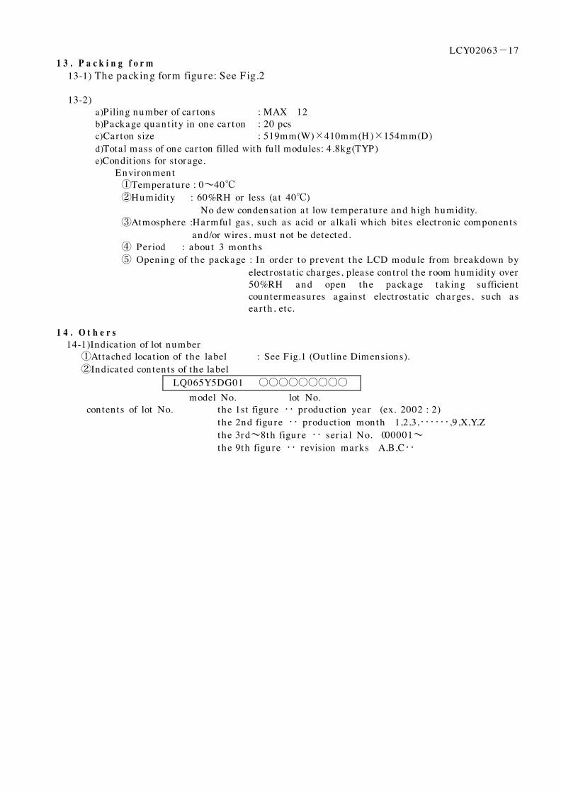
1 4 . O t h e r s 14-1)Indica t ion of lot number ①Attached locat ion of the label : See F ig.1 (Out line Dimensions). ②Indica ted contents of the label
LQ065Y5DG01 ○○○○○○○○○ model No. lot No. contents of lot No. the 1st figure ‥ product ion year (ex. 2002 : 2)
t he 2nd figu re ‥ product ion month 1,2,3,‥‥‥,9,X,Y,Z the 3rd~8th figu re ‥ ser ia l No. 000001~ t he 9th figure ‥ revision marks A,B,C‥

LCY02063-18 1 5 . R e l i a b i l i t y T e s t C o n d i t i o n s f o r T F T - L C D M o d u l e
Table 15-1 Remark) Temperature condit ion is based on opera t ing tempera ture condit ions on 6.-Table 6-1.
No. Test items Test condit ions 1 High tempera ture
storage test Ta= +85℃ 240h
2 Low temperature storage test
Ta=-40℃ 240h
3 High tempera ture a n d h igh humidity opera t ing test
Tp=+60℃ 90%RH 240h
4 High tempera ture opera t ing test
Tp= +85℃ 240h
5 Low temperature opera t ing test
Ta=-30℃ 240h
6 Electro stat ic discharge test
±200V・200pF(0Ω) 1 t ime for each terminals
7 Shock test 980m/s2・6ms, ±X;±Y;±Z 3 t imes for each direct ion (J IS C0041, A-7 Condit ion C)
8 Vibrat ion test Frequency r a nge:8~33.3H z, Stroke:1.3mm Frequency r a nge:33.3H z~400H z, Accelera t ion:28.4m/s2 Sweep cycle:15 minutes X,Z 2 hours for each direct ions, 4 hours for Y direct ion 【caut ion】(tota l 8 hours) (J IS D1601)
9 Heat shock test Ta= -40℃ ~ +85℃ / 200 cycles (0.5h ) (0.5h )
【Note】Ta= Ambient temperature, Tp= Panel temperature 【Check items】In the standard condit ion , there sha ll be no pract ica l problems tha t may affect the
display funct ion . 【caut ion】 X,Y,Z direct ions are shown as follows:
X Y
Z

LCY02063-19
Fig.1 Outline dimensions

F ig.2-1 Input signa l waveform
LAST-1 LAST 1 2
Thlpc Twlp
TsulpsTsusp Thsp
Twsp
Tcwh Tcwl
Tcr Tcf
Tsud Thd
1/fck
0.7VSHD
0.3VSHD
0.7VSHD 0.7VSHD
(D1、n) (D2、n)
0.3VSH D
0.7VSHD
0.3VSH D 0.3VSHD
0.7VSHD
0.7VSHD
0.3VSHD
DCLK
LS
SPOI(SPIO)
R0~R5 G0~G5 B0~B5
0.3VSH D
0.7VSH D 0.7VSHD
0.3VSHD
CLS
SP S
1/fsp
Tsusps Thsps Trsps Tfsps
1/fsps
1/fcls
Tfcl Trcl
0.3VLS(G) 0.3VLS(G)
0.7VLS(G) 0.7VLS(G)
0.3VLS(G) 0.3VLS(G)0.3VLS(G)
0.7VLS(G)
0.3VLS(G) 0.3VLS(G)
0.7VLS(G)
0.3VLS(G)
0.7VSHD
0.7VSHD
1/flp
Twl
* n =DH 1、DH 2・・
LC
Y02063-20

F ig.2-2 I n p ut signal waveform
CLS
SP S
1 2 7 8 9 486 487 488 ・・
(m,DH1) (m,DH2) (m,DH479) R0~R5 G0~G5 B0~B5
CLS
LS
COM
V0、V3、V5、V7、V9、V10
0.3VLS(G)
Tsulp
0.3VLS(G)
0.7VSHD
90%
10%
90% 10%
90% 10%
10%
90%
Tsucom
Thcom
Tfcom Tsuv0 Th v0
Trcom
Trv0 (Tfv0)
Tfv0 (Trv0)
(m,DH480)
* m = D1 ~
LC
Y02063-21
Hor izon ta l inva lid da ta per iod Hor izon ta l inva lid da ta per iod

LCY02063-23
(Appe n dix) Adjust ing method of opt imum common elect rode DC bias volt age
To obta in opt imum DC bia s volt a ge of com m on elect r ode dr ivin g s ign a l (VCDC), photoelect r ic devices a r e ver y effect ive, a n d t h e a ccu r a cy is wit h 0.1V. (In visu a l exa m in a t ion m et h od , t h e accuracy is abou t 0.5V because of the difference among individua ls.) To gain opt imum common elect rode DC bias, there is the method tha t uses photoelectr ic devices. Measuremen t of flicker DC bias voltage is adjusted so as to minimize VSY flicker .
Output voltage
P h ot o-elect r ic device
LCD module
VCDC Oscilloscope
F ig. A Mea su r em en t syst em
《Measurement of flicker》 P h ot oe lect r ic output voltage is measured by an oscilloscope a t a system show in Fig. A. DC bias voltage must be adjusted so as to minimize the VSY flicker with DC bias voltage changing slowly. (F ig.B) DC bias : Opt imum DC bias : Opt imum + 1V
F ig. B Waveforms of flicker