Embed Size (px)
Citation preview

State Institute of Rehabilitation Krauss
Technical Investigation, Part Two
Elizabeth C. Krauss | Mechanical Option | September 18, 2013
T e c h n i c a l R e p o r t I | 1
The State Institute of Rehabilitation Krauss
Technical Investigation, Part Two ................................................................................................................. 0
Executive Summary ....................................................................................................................................... 2
Building Summary ......................................................................................................................................... 2
Building History ......................................................................................................................................... 2
Mechanical Summary................................................................................................................................ 3
System Design Load Estimation .................................................................................................................... 3
Assumptions .............................................................................................................................................. 3
Internal/External Environments ............................................................................................................... 4
Block Layout .............................................................................................................................................. 4
.................................................................................................................................................................. 5
.................................................................................................................................................................. 5
Design Occupancies .................................................................................................................................. 6
Lighting Loads ........................................................................................................................................... 6
Miscellaneous Equipment Loads .............................................................................................................. 6
System Design Load Estimations- Results ..................................................................................................... 6
System Energy Consumption & Operating Costs .......................................................................................... 8
System Comparison .................................................................................................................................. 8
Monthly Energy Usage .............................................................................................................................. 9
Cost of Energy Usage ................................................................................................................................ 9
Environmental Impact ............................................................................................................................... 9
Mechanical Energy Use, break down ...................................................................................................... 10
References .............................................................................................................................................. 11
APPENDIX A-Weather ................................................................................................................................. 12
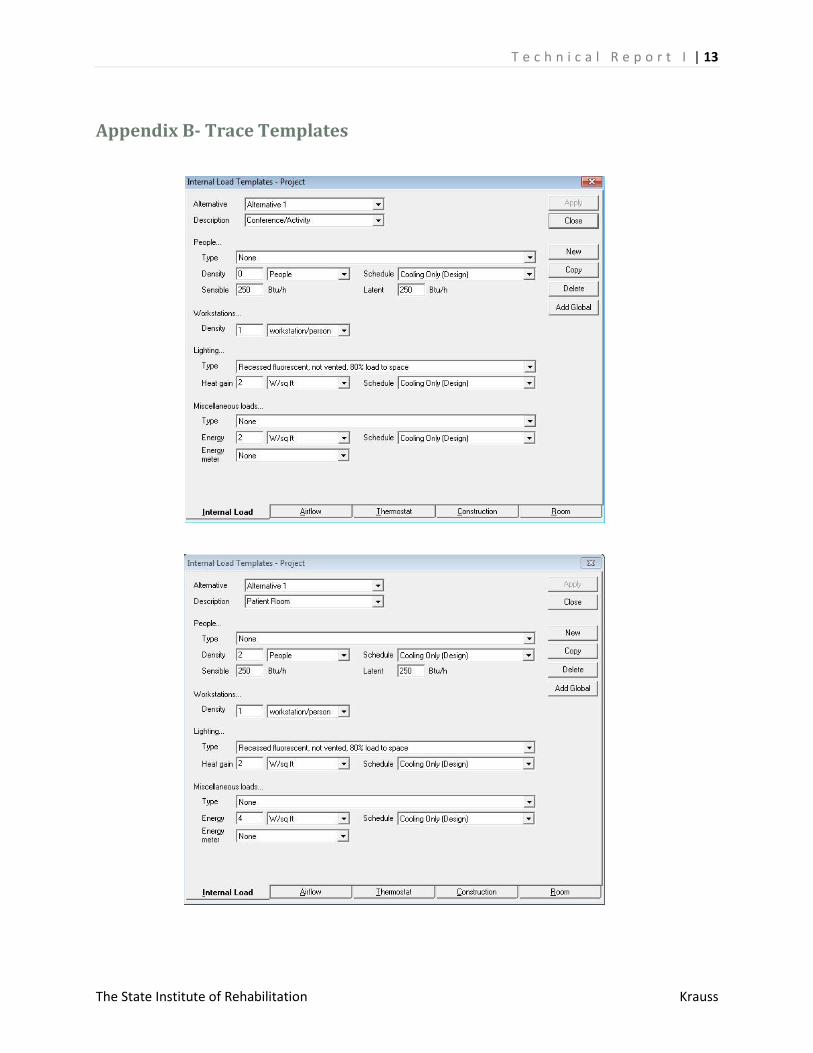
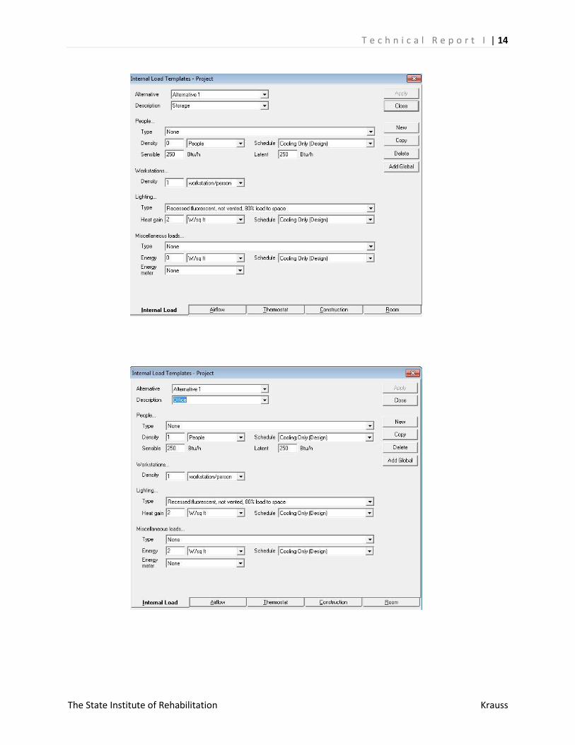
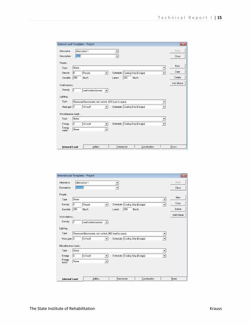
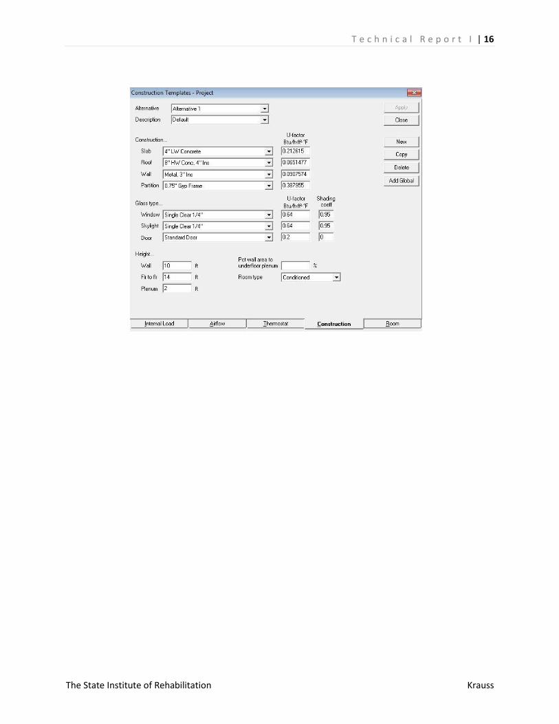
Appendix B- Trace Templates ..................................................................................................................... 13
Appendix C- Zone Checksums ..................................................................................................................... 17
T e c h n i c a l R e p o r t I | 2
The State Institute of Rehabilitation Krauss
Executive Summary The following report is an in depth investigation into the mechanical requirements of the
Institute of Rehabilitation as it now stands. Using what information was available on the building; the
heating and cooling loads of the building were calculated and, furthermore, analyzed. These results
were compared to the design which currently handles the loads presented by the building.
The load and ventilation calculations themselves were done via block load. Bundles of rooms
with similar exterior exposures and characteristics were grouped to create a comprehensive, but
intimate, look at the sufficiency of the in-place system to serve the buildings’ needs.
To the same extent, the resulting loads were analyzed alongside the building’s existing
equipment to generate an energy consumption profile and building energy expenditure summary.
Finally, the energy usage of the building was analyzed against emission profiles to gain a better
understanding about the building not just in terms of its usage but also its contribution to pollution and
exhaust profiles.
Building Summary
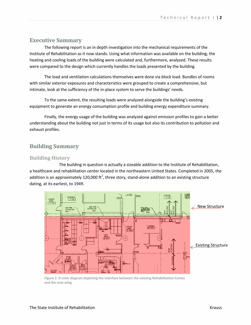
Building History The building in question is actually a sizeable addition to the Institute of Rehabilitation,
a healthcare and rehabilitation center located in the northeastern United States. Completed in 2005, the
addition is an approximately 120,000 ft2, three story, stand-alone addition to an existing structure
dating, at its earliest, to 1949.
Existing Structure
New Structure
Figure 1: A color diagram depicting the interface between the existing Rehabilitation Center and the new wing
T e c h n i c a l R e p o r t I | 3
The State Institute of Rehabilitation Krauss
The building addition, proposed, designed, and constructed in the early ought’s, was meant to
expand the Institutes’ ability to care for its booming inpatient and outpatient populations. The addition
was built entirely on its own mechanical and chilled water systems to avoid disturbing the operation of
the existing facility, which remained fully operational during construction.
Mechanical Summary Mechanically, the addition abutting the existing structure is a stand-alone. The equipment
installed in the building handles, by itself, the loads generated by building occupants, equipment, and
ambient conditions.
The cooling, heating, and ventilation requirements of the buildings are handled by nine (9)
packaged, variable air volume Rooftop Air Handling Units (RTU’s) and one (1) make-up air unit. Cooling is
provided, in each unit, by direct expansion (dx) cooling coils. The building’s heating requirements are
met, however, by a natural gas fired heating bay.
Three natural-gas fed, 1600 MBH hot water boilers feed the systems zone heat requirements.
The building is zoned for effective space conditioning, and each of the zones is controlled by a single
duct Variable Air Volume unit. The reheat coils on these 137 VAV boxes are fed by the hot water
produced by these three boilers.
Additionally, eight (8) unit heaters and eight (8) cabinet unit heaters provide additional heating
when needed. For the sake of this report, they have been neglected and their capacities have been
blanketed under the “heating plant” in the Trane 700 model.
System Design Load Estimation
Assumptions Though all efforts have been made in this report to accurately represent the building in
question, some simplifications have been made in order to ease the analysis. The most significant
simplification made, in this report, is the willful disregard for the application of a diversity factor. Though
not entirely accurate, this simplification is acceptable.
The Institute of Rehabilitation houses both out and in-patient services, requiring mechanical
equipment to be run at all times of the day. Unlike an office building, where occupancy drops off to near
zero during evening and night hours, a healthcare building providing in-patient services will never have
occupancy of zero. Though nighttime occupancy in the Institute of Rehabilitation is a fraction of the
daytime occupancy, the exact ratio of inpatient to outpatient care is variable. It is thus more accurate, in
this modeling exercise, to oversize space conditioning equipment by assuming a diversity factor of 1-
that nighttime and daytime occupancies are exactly the same.
T e c h n i c a l R e p o r t I | 4
The State Institute of Rehabilitation Krauss
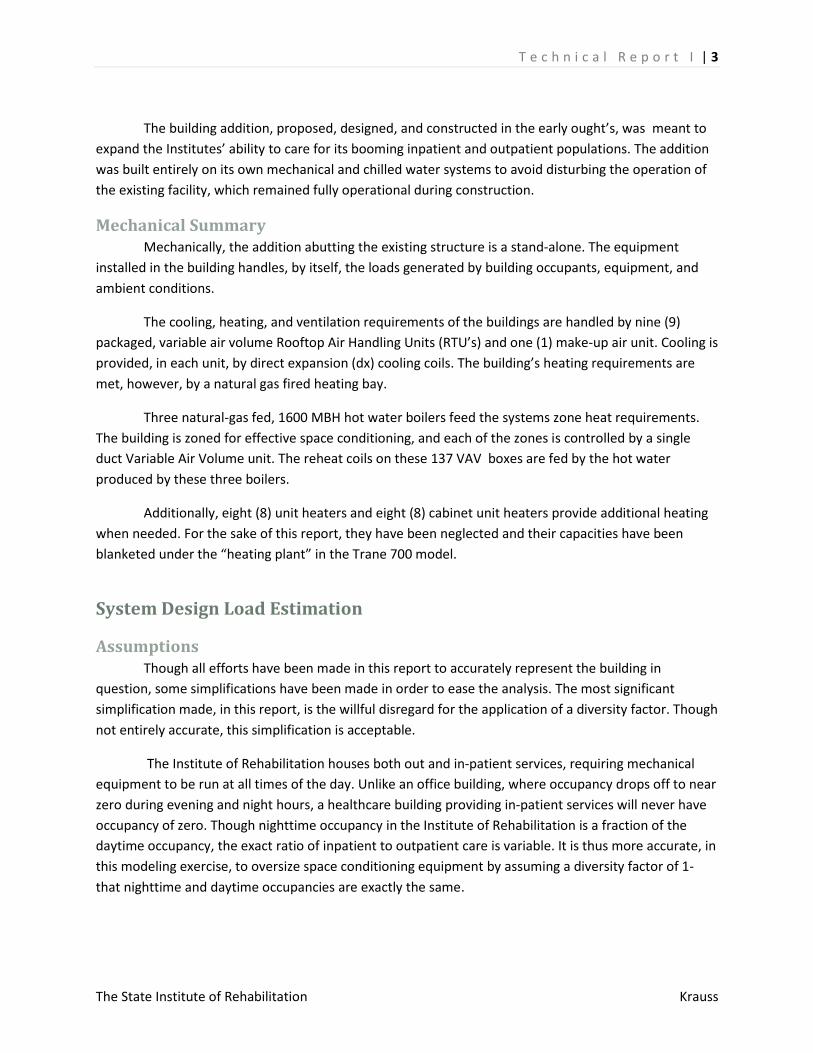
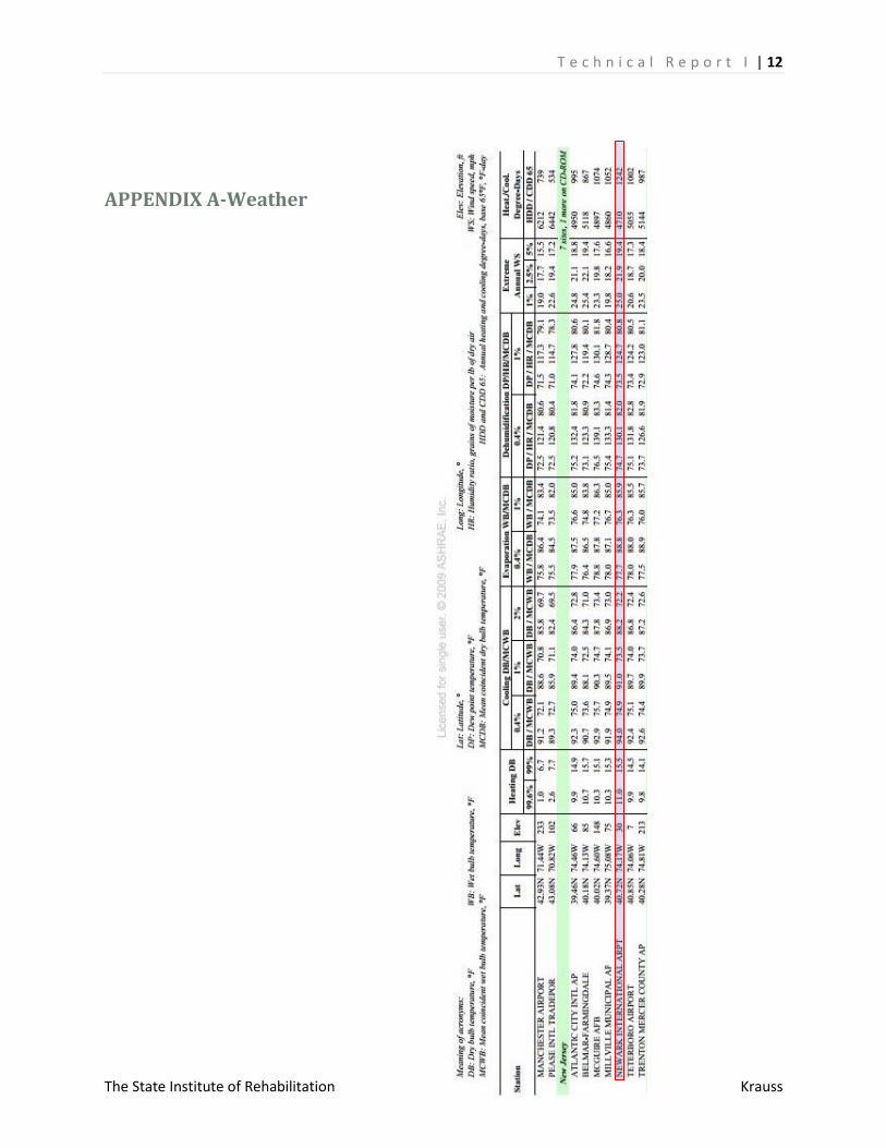
Internal/External Environments The building is closest in location to the Newark International Airport, and so the temperature
data used in the load and energy model is that of Newark. The summary of the temperatures used is
shown below. A more extensive view of the weather data, retrieved from the 2009 ASHRAE Handbook
of Fundamentals, can be found in Appendix A.
It is important to note that because the Institute of Rehabilitation is a healthcare building, and
because a number of the building’s in-patient population is compromised, all effort was made to design
the building with stricter standards. The heating and cooling design temperatures were retrieved from
the 99.6% and 0.4%, respectively.
The indoor environment was designed at a relative humidity (RH) of 50%, for 72oF and 75oF for
the winter and summer, respectively.
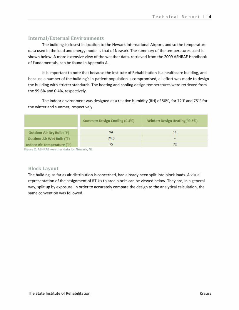
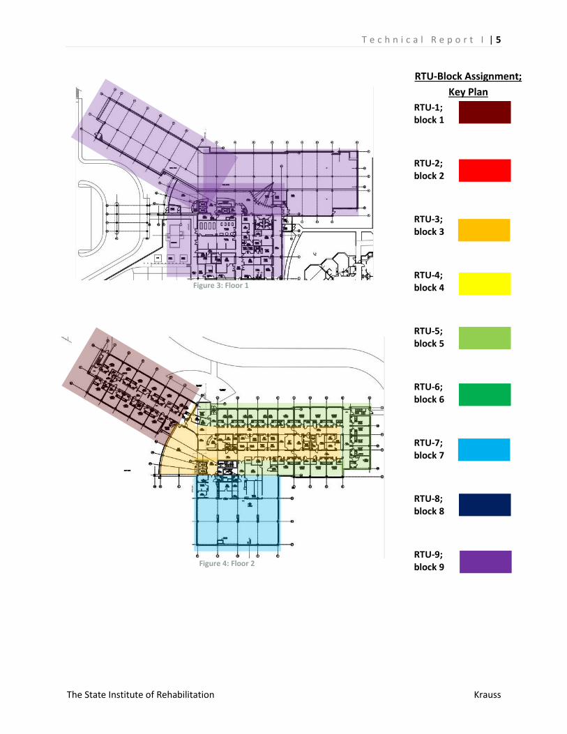
Block Layout The building, as far as air distribution is concerned, had already been split into block loads. A visual
representation of the assignment of RTU’s to area blocks can be viewed below. They are, in a general
way, split up by exposure. In order to accurately compare the design to the analytical calculation, the
same convention was followed.
Figure 2: ASHRAE weather data for Newark, NJ
T e c h n i c a l R e p o r t I | 5
The State Institute of Rehabilitation Krauss
Figure 3: Floor 1
Figure 4: Floor 2
RTU-1; block 1
RTU-2; block 2
RTU-3; block 3
RTU-4; block 4
RTU-5; block 5
RTU-6; block 6
RTU-7; block 7
RTU-8; block 8
RTU-9; block 9
RTU-Block Assignment;
Key Plan
T e c h n i c a l R e p o r t I | 6
The State Institute of Rehabilitation Krauss
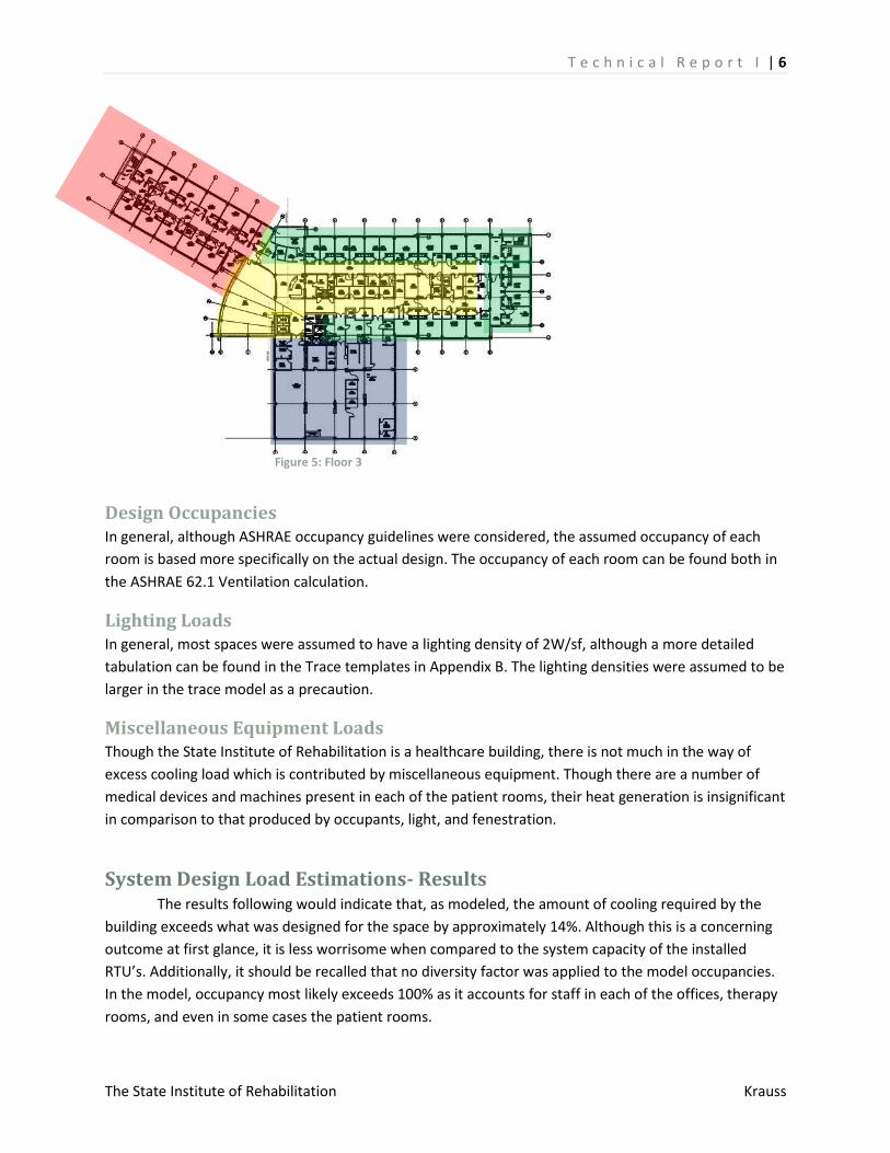
Figure 5: Floor 3
Design Occupancies In general, although ASHRAE occupancy guidelines were considered, the assumed occupancy of each
room is based more specifically on the actual design. The occupancy of each room can be found both in
the ASHRAE 62.1 Ventilation calculation.
Lighting Loads In general, most spaces were assumed to have a lighting density of 2W/sf, although a more detailed
tabulation can be found in the Trace templates in Appendix B. The lighting densities were assumed to be
larger in the trace model as a precaution.
Miscellaneous Equipment Loads Though the State Institute of Rehabilitation is a healthcare building, there is not much in the way of
excess cooling load which is contributed by miscellaneous equipment. Though there are a number of
medical devices and machines present in each of the patient rooms, their heat generation is insignificant
in comparison to that produced by occupants, light, and fenestration.
System Design Load Estimations- Results The results following would indicate that, as modeled, the amount of cooling required by the
building exceeds what was designed for the space by approximately 14%. Although this is a concerning
outcome at first glance, it is less worrisome when compared to the system capacity of the installed
RTU’s. Additionally, it should be recalled that no diversity factor was applied to the model occupancies.
In the model, occupancy most likely exceeds 100% as it accounts for staff in each of the offices, therapy
rooms, and even in some cases the patient rooms.
T e c h n i c a l R e p o r t I | 7
The State Institute of Rehabilitation Krauss
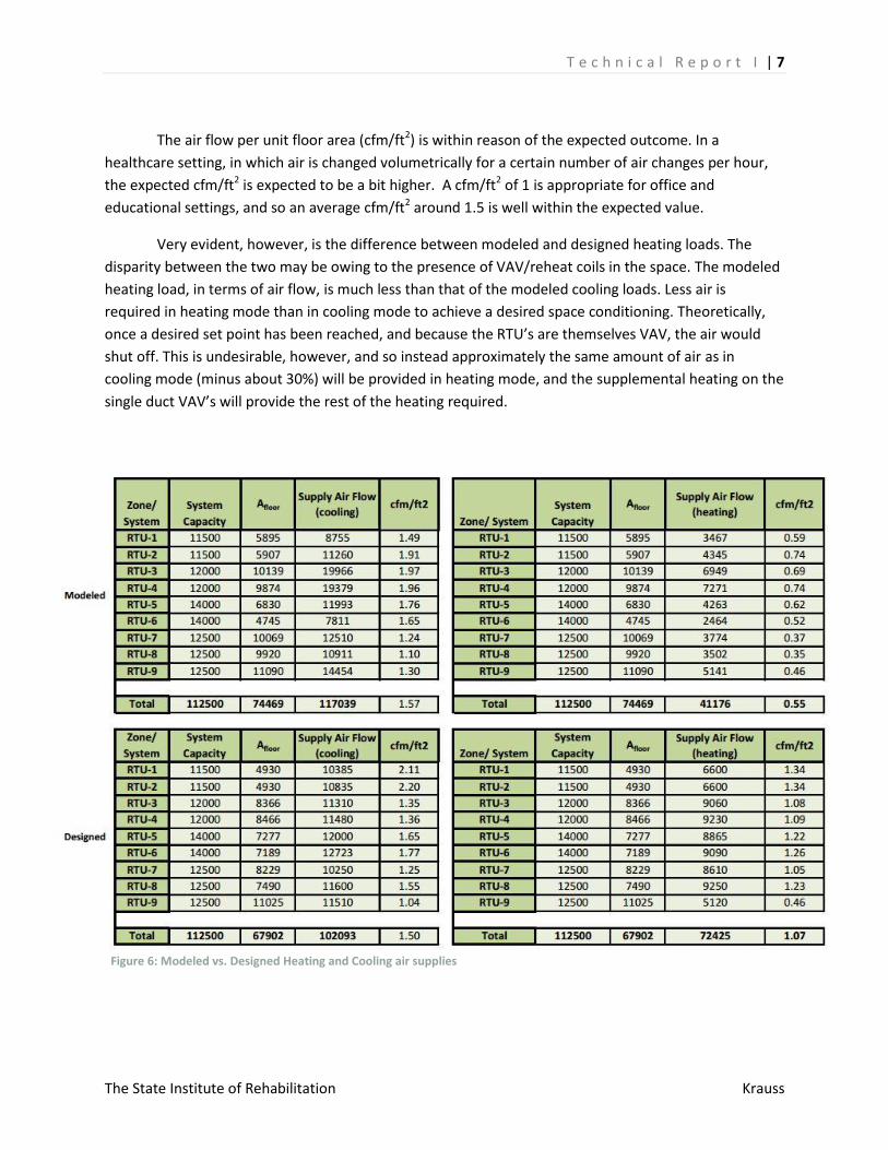
The air flow per unit floor area (cfm/ft2) is within reason of the expected outcome. In a
healthcare setting, in which air is changed volumetrically for a certain number of air changes per hour,
the expected cfm/ft2 is expected to be a bit higher. A cfm/ft2 of 1 is appropriate for office and
educational settings, and so an average cfm/ft2 around 1.5 is well within the expected value.
Very evident, however, is the difference between modeled and designed heating loads. The
disparity between the two may be owing to the presence of VAV/reheat coils in the space. The modeled
heating load, in terms of air flow, is much less than that of the modeled cooling loads. Less air is
required in heating mode than in cooling mode to achieve a desired space conditioning. Theoretically,
once a desired set point has been reached, and because the RTU’s are themselves VAV, the air would
shut off. This is undesirable, however, and so instead approximately the same amount of air as in
cooling mode (minus about 30%) will be provided in heating mode, and the supplemental heating on the
single duct VAV’s will provide the rest of the heating required.
Figure 6: Modeled vs. Designed Heating and Cooling air supplies
T e c h n i c a l R e p o r t I | 8
The State Institute of Rehabilitation Krauss
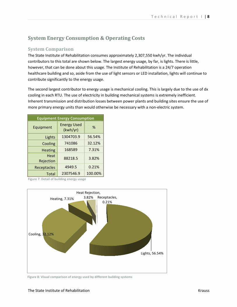
Lights, 56.54%
Cooling, 32.12%
Heating, 7.31%
Heat Rejection, 3.82% Receptacles,
0.21%
System Energy Consumption & Operating Costs
System Comparison The State Institute of Rehabilitation consumes approximately 2,307,550 kwh/yr. The individual
contributors to this total are shown below. The largest energy usage, by far, is lights. There is little,
however, that can be done about this usage. The Institute of Rehabilitation is a 24/7 operation
healthcare building and so, aside from the use of light sensors or LED installation, lights will continue to
contribute significantly to the energy usage.
The second largest contributor to energy usage is mechanical cooling. This is largely due to the use of dx
cooling in each RTU. The use of electricity in building mechanical systems is extremely inefficient.
Inherent transmission and distribution losses between power plants and building sites ensure the use of
more primary energy units than would otherwise be necessary with a non-electric system.
Equipment Energy Consumption
Equipment Energy Used
(kwh/yr) %
Lights 1304703.9 56.54%
Cooling 741086 32.12%
Heating 168589 7.31%
Heat Rejection
88218.5 3.82%
Receptacles 4949.5 0.21%
Total 2307546.9 100.00% Figure 7: Detail of building energy usage
Figure 8: Visual comparison of energy used by different building systems
T e c h n i c a l R e p o r t I | 9
The State Institute of Rehabilitation Krauss
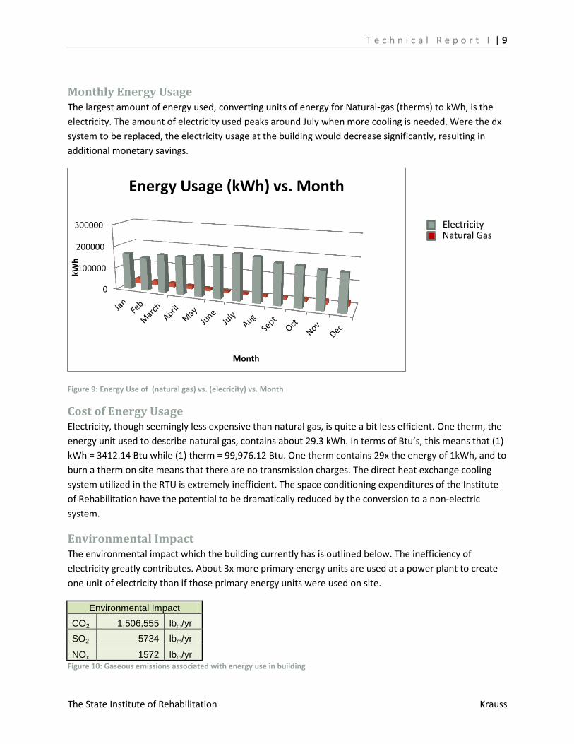
Monthly Energy Usage The largest amount of energy used, converting units of energy for Natural-gas (therms) to kWh, is the
electricity. The amount of electricity used peaks around July when more cooling is needed. Were the dx
system to be replaced, the electricity usage at the building would decrease significantly, resulting in
additional monetary savings.
Figure 9: Energy Use of (natural gas) vs. (elecricity) vs. Month
Cost of Energy Usage Electricity, though seemingly less expensive than natural gas, is quite a bit less efficient. One therm, the
energy unit used to describe natural gas, contains about 29.3 kWh. In terms of Btu’s, this means that (1)
kWh = 3412.14 Btu while (1) therm = 99,976.12 Btu. One therm contains 29x the energy of 1kWh, and to
burn a therm on site means that there are no transmission charges. The direct heat exchange cooling
system utilized in the RTU is extremely inefficient. The space conditioning expenditures of the Institute
of Rehabilitation have the potential to be dramatically reduced by the conversion to a non-electric
system.
Environmental Impact The environmental impact which the building currently has is outlined below. The inefficiency of
electricity greatly contributes. About 3x more primary energy units are used at a power plant to create
one unit of electricity than if those primary energy units were used on site.
Environmental Impact
CO2 1,506,555 lbm/yr
SO2 5734 lbm/yr
NOx 1572 lbm/yr
Figure 10: Gaseous emissions associated with energy use in building
0
100000
200000
300000
kWh
Month
Energy Usage (kWh) vs. Month
Electricity Natural Gas
T e c h n i c a l R e p o r t I | 10
The State Institute of Rehabilitation Krauss
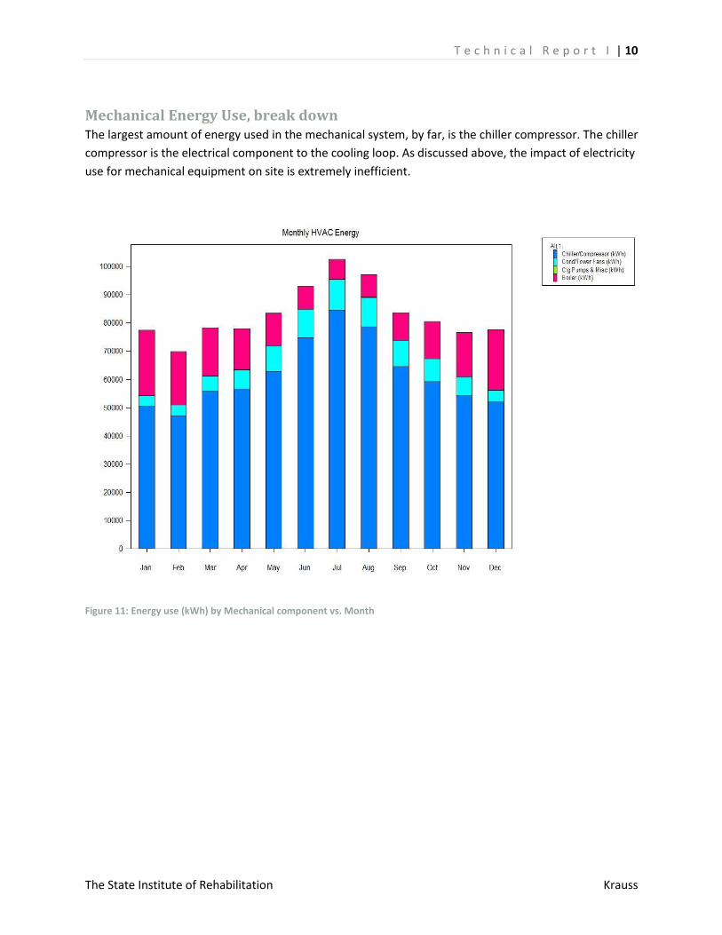
Mechanical Energy Use, break down The largest amount of energy used in the mechanical system, by far, is the chiller compressor. The chiller
compressor is the electrical component to the cooling loop. As discussed above, the impact of electricity
use for mechanical equipment on site is extremely inefficient.
Figure 11: Energy use (kWh) by Mechanical component vs. Month
T e c h n i c a l R e p o r t I | 11
The State Institute of Rehabilitation Krauss
References ASHRAE (2009), Standard 62.1‐2010, Ventilation for Acceptable Indoor Air Quality. American
Society of Heating, Refrigerating, and Air Conditioning Engineers, Inc., Atlanta,GA, 2009.
ASHRAE (2009), Standard 90.1‐2010, Energy Standard for Buildings Except Low‐Rise Residential
Buildings. American Society ofHeating, Refrigerating, and Air Conditioning Engineers, Inc.,
Atlanta,GA, 2009
ASHRAE (2009). 2005 ASHRAE Handbook - Fundamentals. Atlanta, GA: American Society of
Heating Refrigeration and Air Conditioning Engineers, Inc.
T e c h n i c a l R e p o r t I | 12
The State Institute of Rehabilitation Krauss
APPENDIX A-Weather
T e c h n i c a l R e p o r t I | 13
The State Institute of Rehabilitation Krauss
Appendix B- Trace Templates
T e c h n i c a l R e p o r t I | 14
The State Institute of Rehabilitation Krauss
T e c h n i c a l R e p o r t I | 15
The State Institute of Rehabilitation Krauss
T e c h n i c a l R e p o r t I | 16
The State Institute of Rehabilitation Krauss

T e c h n i c a l R e p o r t I | 17
The State Institute of Rehabilitation Krauss
Appendix C- Zone Checksums
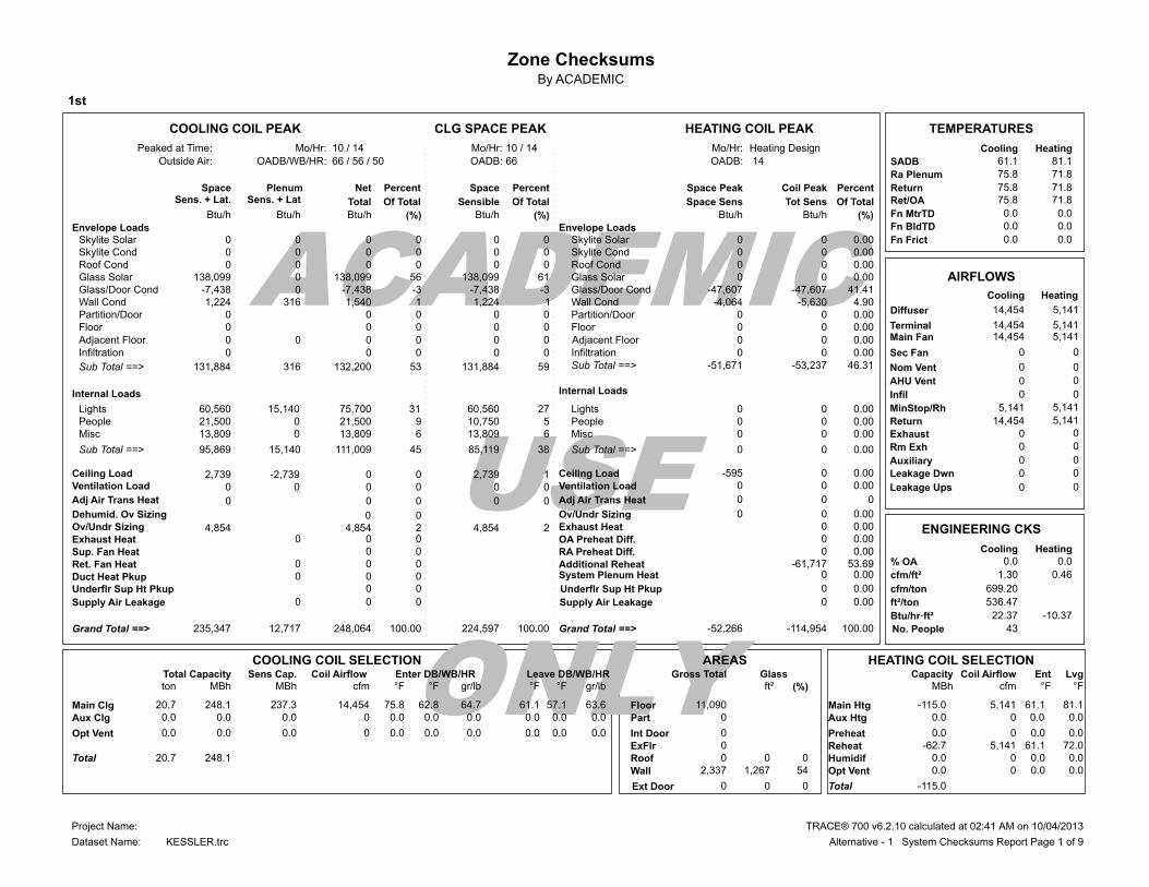
Zone ChecksumsBy ACADEMIC
1st
ACADEMIC
USE
ONLY
HEATING COIL PEAKCLG SPACE PEAKCOOLING COIL PEAK TEMPERATURES
Heating DesignMo/Hr:10 / 14Mo/Hr:10 / 14Mo/Hr:Peaked at Time: Cooling Heating
SADBOADB: 14OADB:66 / 56 / 50OADB/WB/HR:Outside Air: 61.1 81.1
Ra Plenum 75.8 71.8
ReturnPercentCoil PeakSpace PeakSpace PercentPercentNetPlenumSpace 75.8 71.8Ret/OASens. + Lat. Of TotalTot SensSpace SensOf TotalSensibleOf TotalTotalSens. + Lat 71.8 75.8
0.0 0.0Fn MtrTDBtu/h (%)Btu/hBtu/h(%)Btu/h(%)Btu/hBtu/h 0.0 0.0Fn BldTDEnvelope Loads 0.0 0.0Fn Frict 0Skylite Solar 0.00 0 0 0 0 0 0 0
0Skylite Cond 0.00 0 0 0 0 0 0 0 0Roof Cond 0.00 0 0 0 0 0 0 0
0.00 138,099Glass Solar 0 0 61 138,099 56 138,099 0-7,438Glass/Door Cond -47,607 41.41-47,607-3-7,438-3-7,438 0
AIRFLOWS
HeatingCooling 1,224Wall Cond 4.90-5,630-4,064 1 1,224 1 1,540 316
0Partition/Door 0.00 0 0 0 0 0 0 0Floor 0.00 0 0 0 0 0
Sec Fan 0.00 0Infiltration 0 0 0 0 0 0
5,141 5,141MinStop/Rh
46.31 131,884Sub Total ==> -53,237-51,671 59 131,884 53 132,200 316
14,454Return 5,141
Internal Loads
0 0Exhaust
60,560Lights 0.00 0 0 27 60,560 31 75,700 15,140
0 0Rm Exh
21,500People 0.00 0 5 10,750 9
0 0Auxiliary
13,809Misc 0.00 0 0 6 13,809 6 13,809 0
95,869Sub Total ==> 0.00 0 0 38 85,119 45 111,009 15,140
2,739Ceiling Load 0.000-595 1 2,739 0 0-2,739 0Ventilation Load 0.00 0 0 0 0 0 0 0
Sup. Fan Heat 0 0
ENGINEERING CKS
HeatingCooling
Ret. Fan Heat 0 0 0 % OA 0.0 0.0
Duct Heat Pkup 0 0 0 0.46 1.30cfm/ft²
4,854Ov/Undr Sizing
0.00 0 0
2 4,854 2 4,854
699.20cfm/ton
Exhaust Heat
0.00 0 0 0
536.47ft²/ton
-10.37 22.37Btu/hr·ft²
43No. People 235,347Grand Total ==> 100.00-114,954-52,266100.00 224,597100.00 248,064 12,717
AREAS HEATING COIL SELECTIONCOOLING COIL SELECTIONTotal Capacity Sens Cap. Coil Airflow Enter DB/WB/HR Leave DB/WB/HR Gross Total Glass Coil Airflow Ent LvgCapacityton MBh MBh cfm °F °F gr/lb °F °F gr/lb ft² (%) °F°FcfmMBh
Floor 11,090 Main Htg -115.0 5,141 61.1 81.1 20.7 248.1 237.3 14,454 75.8 62.8 64.7 61.1 57.1 63.6Main ClgPart 0 Aux Htg 0.0 0.0 0.0 0 0.0 0.0 0.0 0 0.0 0.0 0.0 0.0 0.0 0.0Aux Clg
ExFlr 0 0.0Preheat 0.0 0.0 0 0.0 0.0 0.0 0 0.0 0.0 0.0 0.0 0.0 0.0Opt Vent
Roof 0 0 0Reheat -62.7 72.0 61.1 5,141
Wall 2,337 1,267 54Humidif 0.0 0 0.0 0.0 20.7 248.1TotalOpt Vent 0.0 0.0 0.0 0
-115.0Total
Envelope LoadsSkylite SolarSkylite CondRoof CondGlass SolarGlass/Door CondWall CondPartition/DoorFloor
InfiltrationSub Total ==>
LightsPeopleMisc
Sub Total ==>
Ceiling LoadVentilation Load
System Plenum HeatAdditional Reheat
OA Preheat Diff.
Ov/Undr SizingExhaust Heat
RA Preheat Diff.
Grand Total ==>
Internal Loads
-61,717 0
0 0
0.00
0.00
0.00 53.69
0
Supply Air Leakage
66
Dehumid. Ov Sizing 0 0
Adj Air Trans Heat 0 0 0 0 0 Adj Air Trans Heat 0 0 0Leakage Ups
Leakage Dwn
0 0Infil
AHU Vent
Nom Vent
Main FanTerminal
Adjacent Floor
Diffuser
Supply Air Leakage
Underflr Sup Ht Pkup Underflr Sup Ht Pkup
Adjacent Floor 0 0 0 0
0 0
0 0 0
0 0
0 0 0 0.00
0 0.00
0 0.00
14,454
14,454 14,454
0
0
0
0
0
5,141
5,141 5,141
0
0
0
0
0
0 21,500 0
Int Door 0
Ext Door 0 0 0
TRACE® 700 v6.2.10 calculated at 02:41 AM on 10/04/2013Project Name:
Dataset Name: Alternative - 1 System Checksums Report Page 1 of 9KESSLER.trc
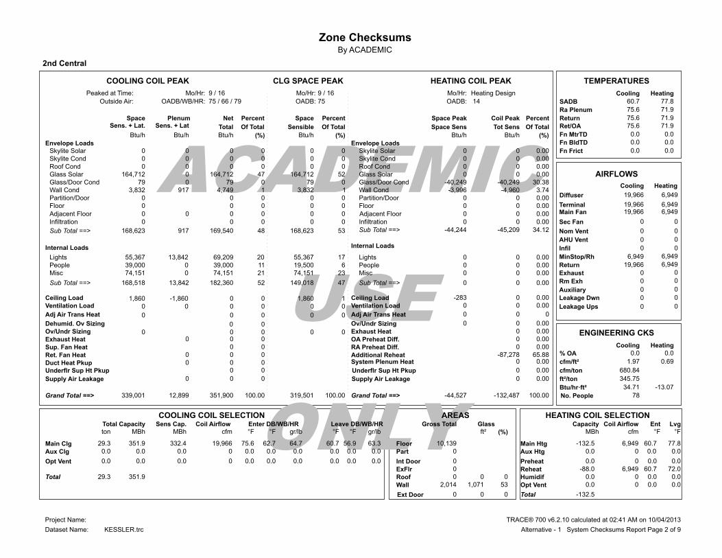
Zone ChecksumsBy ACADEMIC
2nd Central
ACADEMIC
USE
ONLY
HEATING COIL PEAKCLG SPACE PEAKCOOLING COIL PEAK TEMPERATURES
Heating DesignMo/Hr:9 / 16Mo/Hr:9 / 16Mo/Hr:Peaked at Time: Cooling Heating
SADBOADB: 14OADB:75 / 66 / 79OADB/WB/HR:Outside Air: 60.7 77.8
Ra Plenum 75.6 71.9
ReturnPercentCoil PeakSpace PeakSpace PercentPercentNetPlenumSpace 75.6 71.9Ret/OASens. + Lat. Of TotalTot SensSpace SensOf TotalSensibleOf TotalTotalSens. + Lat 71.9 75.6
0.0 0.0Fn MtrTDBtu/h (%)Btu/hBtu/h(%)Btu/h(%)Btu/hBtu/h 0.0 0.0Fn BldTDEnvelope Loads 0.0 0.0Fn Frict 0Skylite Solar 0.00 0 0 0 0 0 0 0
0Skylite Cond 0.00 0 0 0 0 0 0 0 0Roof Cond 0.00 0 0 0 0 0 0 0
0.00 164,712Glass Solar 0 0 52 164,712 47 164,712 0 79Glass/Door Cond -40,249 30.38-40,249 0 79 0 79 0
AIRFLOWS
HeatingCooling 3,832Wall Cond 3.74-4,960-3,996 1 3,832 1 4,749 917
0Partition/Door 0.00 0 0 0 0 0 0 0Floor 0.00 0 0 0 0 0
Sec Fan 0.00 0Infiltration 0 0 0 0 0 0
6,949 6,949MinStop/Rh
34.12 168,623Sub Total ==> -45,209-44,244 53 168,623 48 169,540 917
19,966Return 6,949
Internal Loads
0 0Exhaust
55,367Lights 0.00 0 0 17 55,367 20 69,209 13,842
0 0Rm Exh
39,000People 0.00 0 6 19,500 11
0 0Auxiliary
74,151Misc 0.00 0 0 23 74,151 21 74,151 0
168,518Sub Total ==> 0.00 0 0 47 149,018 52 182,360 13,842
1,860Ceiling Load 0.000-283 1 1,860 0 0-1,860 0Ventilation Load 0.00 0 0 0 0 0 0 0
Sup. Fan Heat 0 0
ENGINEERING CKS
HeatingCooling
Ret. Fan Heat 0 0 0 % OA 0.0 0.0
Duct Heat Pkup 0 0 0 0.69 1.97cfm/ft²
0Ov/Undr Sizing
0.00 0 0
0 0 0 0
680.84cfm/ton
Exhaust Heat
0.00 0 0 0
345.75ft²/ton
-13.07 34.71Btu/hr·ft²
78No. People 339,001Grand Total ==> 100.00-132,487-44,527100.00 319,501100.00 351,900 12,899
AREAS HEATING COIL SELECTIONCOOLING COIL SELECTIONTotal Capacity Sens Cap. Coil Airflow Enter DB/WB/HR Leave DB/WB/HR Gross Total Glass Coil Airflow Ent LvgCapacityton MBh MBh cfm °F °F gr/lb °F °F gr/lb ft² (%) °F°FcfmMBh
Floor 10,139 Main Htg -132.5 6,949 60.7 77.8 29.3 351.9 332.4 19,966 75.6 62.7 64.7 60.7 56.9 63.3Main ClgPart 0 Aux Htg 0.0 0.0 0.0 0 0.0 0.0 0.0 0 0.0 0.0 0.0 0.0 0.0 0.0Aux Clg
ExFlr 0 0.0Preheat 0.0 0.0 0 0.0 0.0 0.0 0 0.0 0.0 0.0 0.0 0.0 0.0Opt Vent
Roof 0 0 0Reheat -88.0 72.0 60.7 6,949
Wall 2,014 1,071 53Humidif 0.0 0 0.0 0.0 29.3 351.9TotalOpt Vent 0.0 0.0 0.0 0
-132.5Total
Envelope LoadsSkylite SolarSkylite CondRoof CondGlass SolarGlass/Door CondWall CondPartition/DoorFloor
InfiltrationSub Total ==>
LightsPeopleMisc
Sub Total ==>
Ceiling LoadVentilation Load
System Plenum HeatAdditional Reheat
OA Preheat Diff.
Ov/Undr SizingExhaust Heat
RA Preheat Diff.
Grand Total ==>
Internal Loads
-87,278 0
0 0
0.00
0.00
0.00 65.88
0
Supply Air Leakage
75
Dehumid. Ov Sizing 0 0
Adj Air Trans Heat 0 0 0 0 0 Adj Air Trans Heat 0 0 0Leakage Ups
Leakage Dwn
0 0Infil
AHU Vent
Nom Vent
Main FanTerminal
Adjacent Floor
Diffuser
Supply Air Leakage
Underflr Sup Ht Pkup Underflr Sup Ht Pkup
Adjacent Floor 0 0 0 0
0 0
0 0 0
0 0
0 0 0 0.00
0 0.00
0 0.00
19,966
19,966 19,966
0
0
0
0
0
6,949
6,949 6,949
0
0
0
0
0
0 39,000 0
Int Door 0
Ext Door 0 0 0
TRACE® 700 v6.2.10 calculated at 02:41 AM on 10/04/2013Project Name:
Dataset Name: Alternative - 1 System Checksums Report Page 2 of 9KESSLER.trc

Zone ChecksumsBy ACADEMIC
2nd East
ACADEMIC
USE
ONLY
HEATING COIL PEAKCLG SPACE PEAKCOOLING COIL PEAK TEMPERATURES
Heating DesignMo/Hr:10 / 13Mo/Hr:10 / 13Mo/Hr:Peaked at Time: Cooling Heating
SADBOADB: 14OADB:64 / 55 / 48OADB/WB/HR:Outside Air: 61.1 80.2
Ra Plenum 75.9 71.6
ReturnPercentCoil PeakSpace PeakSpace PercentPercentNetPlenumSpace 75.9 71.6Ret/OASens. + Lat. Of TotalTot SensSpace SensOf TotalSensibleOf TotalTotalSens. + Lat 71.6 75.9
0.0 0.0Fn MtrTDBtu/h (%)Btu/hBtu/h(%)Btu/h(%)Btu/hBtu/h 0.0 0.0Fn BldTDEnvelope Loads 0.0 0.0Fn Frict 0Skylite Solar 0.00 0 0 0 0 0 0 0
0Skylite Cond 0.00 0 0 0 0 0 0 0 0Roof Cond 0.75-600 0 0 0 0-162-162
0.00 67,076Glass Solar 0 0 35 67,076 31 67,076 0-4,015Glass/Door Cond -21,793 27.14-21,793-2-4,015-2-4,015 0
AIRFLOWS
HeatingCooling 4,589Wall Cond 16.93-13,598-11,233 2 4,589 3 5,531 943
0Partition/Door 0.00 0 0 0 0 0 0 0Floor 0.00 0 0 0 0 0
Sec Fan 0.00 0Infiltration 0 0 0 0 0 0
3,774 3,774MinStop/Rh
44.81 67,650Sub Total ==> -35,991-33,026 35 67,650 32 68,431 781
12,510Return 3,774
Internal Loads
0 0Exhaust
54,985Lights 0.00 0 0 28 54,985 32 68,731 13,746
0 0Rm Exh
19,000People 0.00 0 5 9,500 9
0 0Auxiliary
59,530Misc 0.00 0 0 31 59,530 28 59,530 0
133,514Sub Total ==> 0.00 0 0 64 124,014 68 147,261 13,746
2,707Ceiling Load 0.000-1,279 1 2,707 0 0-2,707 0Ventilation Load 0.00 0 0 0 0 0 0 0
Sup. Fan Heat 0 0
ENGINEERING CKS
HeatingCooling
Ret. Fan Heat 0 0 0 % OA 0.0 0.0
Duct Heat Pkup 0 0 0 0.37 1.24cfm/ft²
0Ov/Undr Sizing
0.00 0 0
0 0 0 0
695.98cfm/ton
Exhaust Heat
0.00 0 0 0
560.19ft²/ton
-7.98 21.42Btu/hr·ft²
38No. People 203,872Grand Total ==> 100.00-80,312-34,305100.00 194,372100.00 215,692 11,820
AREAS HEATING COIL SELECTIONCOOLING COIL SELECTIONTotal Capacity Sens Cap. Coil Airflow Enter DB/WB/HR Leave DB/WB/HR Gross Total Glass Coil Airflow Ent LvgCapacityton MBh MBh cfm °F °F gr/lb °F °F gr/lb ft² (%) °F°FcfmMBh
Floor 10,069 Main Htg -80.3 3,774 61.1 80.2 18.0 215.7 206.2 12,510 75.9 62.8 64.8 61.1 57.2 63.7Main ClgPart 0 Aux Htg 0.0 0.0 0.0 0 0.0 0.0 0.0 0 0.0 0.0 0.0 0.0 0.0 0.0Aux Clg
ExFlr 0 0.0Preheat 0.0 0.0 0 0.0 0.0 0.0 0 0.0 0.0 0.0 0.0 0.0 0.0Opt Vent
Roof 160 0 0Reheat -46.0 72.0 61.1 3,774
Wall 3,166 580 18Humidif 0.0 0 0.0 0.0 18.0 215.7TotalOpt Vent 0.0 0.0 0.0 0
-80.3Total
Envelope LoadsSkylite SolarSkylite CondRoof CondGlass SolarGlass/Door CondWall CondPartition/DoorFloor
InfiltrationSub Total ==>
LightsPeopleMisc
Sub Total ==>
Ceiling LoadVentilation Load
System Plenum HeatAdditional Reheat
OA Preheat Diff.
Ov/Undr SizingExhaust Heat
RA Preheat Diff.
Grand Total ==>
Internal Loads
-44,321 0
0 0
0.00
0.00
0.00 55.19
0
Supply Air Leakage
64
Dehumid. Ov Sizing 0 0
Adj Air Trans Heat 0 0 0 0 0 Adj Air Trans Heat 0 0 0Leakage Ups
Leakage Dwn
0 0Infil
AHU Vent
Nom Vent
Main FanTerminal
Adjacent Floor
Diffuser
Supply Air Leakage
Underflr Sup Ht Pkup Underflr Sup Ht Pkup
Adjacent Floor 0 0 0 0
0 0
0 0 0
0 0
0 0 0 0.00
0 0.00
0 0.00
12,510
12,510 12,510
0
0
0
0
0
3,774
3,774 3,774
0
0
0
0
0
0 19,000 0
Int Door 0
Ext Door 0 0 0
TRACE® 700 v6.2.10 calculated at 02:41 AM on 10/04/2013Project Name:
Dataset Name: Alternative - 1 System Checksums Report Page 3 of 9KESSLER.trc
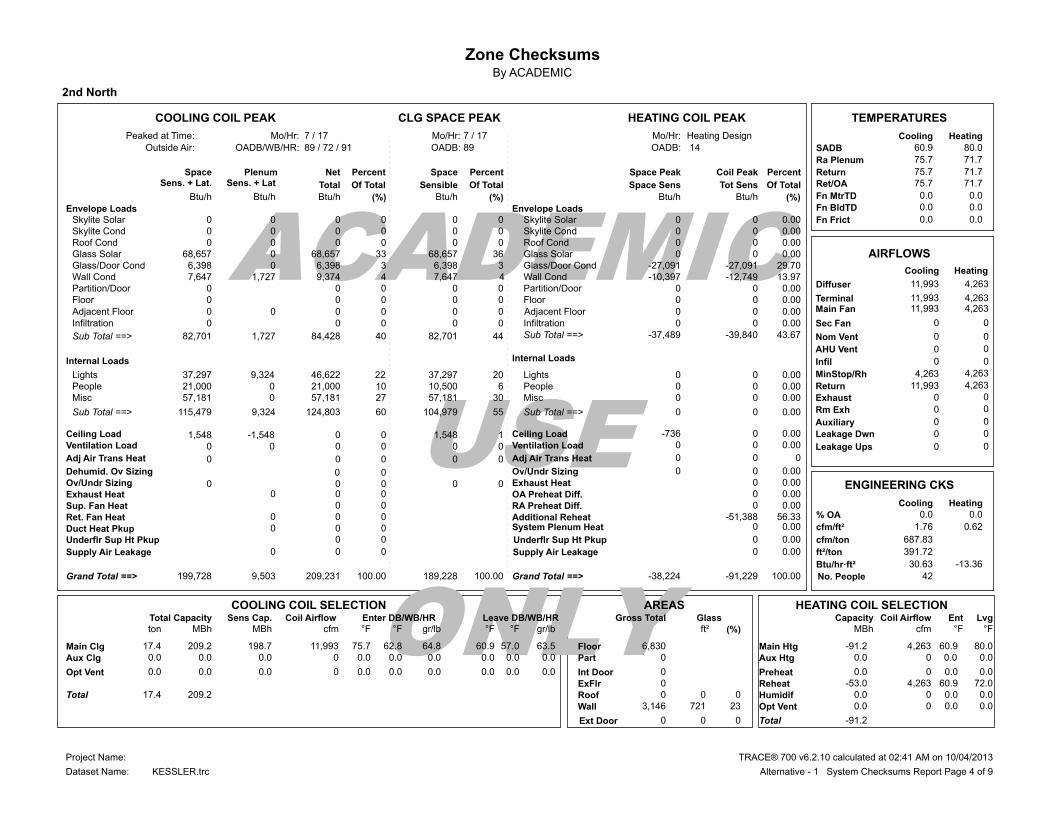
Zone ChecksumsBy ACADEMIC
2nd North
ACADEMIC
USE
ONLY
HEATING COIL PEAKCLG SPACE PEAKCOOLING COIL PEAK TEMPERATURES
Heating DesignMo/Hr:7 / 17Mo/Hr:7 / 17Mo/Hr:Peaked at Time: Cooling Heating
SADBOADB: 14OADB:89 / 72 / 91OADB/WB/HR:Outside Air: 60.9 80.0
Ra Plenum 75.7 71.7
ReturnPercentCoil PeakSpace PeakSpace PercentPercentNetPlenumSpace 75.7 71.7Ret/OASens. + Lat. Of TotalTot SensSpace SensOf TotalSensibleOf TotalTotalSens. + Lat 71.7 75.7
0.0 0.0Fn MtrTDBtu/h (%)Btu/hBtu/h(%)Btu/h(%)Btu/hBtu/h 0.0 0.0Fn BldTDEnvelope Loads 0.0 0.0Fn Frict 0Skylite Solar 0.00 0 0 0 0 0 0 0
0Skylite Cond 0.00 0 0 0 0 0 0 0 0Roof Cond 0.00 0 0 0 0 0 0 0
0.00 68,657Glass Solar 0 0 36 68,657 33 68,657 0 6,398Glass/Door Cond -27,091 29.70-27,091 3 6,398 3 6,398 0
AIRFLOWS
HeatingCooling 7,647Wall Cond 13.97-12,749-10,397 4 7,647 4 9,374 1,727
0Partition/Door 0.00 0 0 0 0 0 0 0Floor 0.00 0 0 0 0 0
Sec Fan 0.00 0Infiltration 0 0 0 0 0 0
4,263 4,263MinStop/Rh
43.67 82,701Sub Total ==> -39,840-37,489 44 82,701 40 84,428 1,727
11,993Return 4,263
Internal Loads
0 0Exhaust
37,297Lights 0.00 0 0 20 37,297 22 46,622 9,324
0 0Rm Exh
21,000People 0.00 0 6 10,500 10
0 0Auxiliary
57,181Misc 0.00 0 0 30 57,181 27 57,181 0
115,479Sub Total ==> 0.00 0 0 55 104,979 60 124,803 9,324
1,548Ceiling Load 0.000-736 1 1,548 0 0-1,548 0Ventilation Load 0.00 0 0 0 0 0 0 0
Sup. Fan Heat 0 0
ENGINEERING CKS
HeatingCooling
Ret. Fan Heat 0 0 0 % OA 0.0 0.0
Duct Heat Pkup 0 0 0 0.62 1.76cfm/ft²
0Ov/Undr Sizing
0.00 0 0
0 0 0 0
687.83cfm/ton
Exhaust Heat
0.00 0 0 0
391.72ft²/ton
-13.36 30.63Btu/hr·ft²
42No. People 199,728Grand Total ==> 100.00-91,229-38,224100.00 189,228100.00 209,231 9,503
AREAS HEATING COIL SELECTIONCOOLING COIL SELECTIONTotal Capacity Sens Cap. Coil Airflow Enter DB/WB/HR Leave DB/WB/HR Gross Total Glass Coil Airflow Ent LvgCapacityton MBh MBh cfm °F °F gr/lb °F °F gr/lb ft² (%) °F°FcfmMBh
Floor 6,830 Main Htg -91.2 4,263 60.9 80.0 17.4 209.2 198.7 11,993 75.7 62.8 64.8 60.9 57.0 63.5Main ClgPart 0 Aux Htg 0.0 0.0 0.0 0 0.0 0.0 0.0 0 0.0 0.0 0.0 0.0 0.0 0.0Aux Clg
ExFlr 0 0.0Preheat 0.0 0.0 0 0.0 0.0 0.0 0 0.0 0.0 0.0 0.0 0.0 0.0Opt Vent
Roof 0 0 0Reheat -53.0 72.0 60.9 4,263
Wall 3,146 721 23Humidif 0.0 0 0.0 0.0 17.4 209.2TotalOpt Vent 0.0 0.0 0.0 0
-91.2Total
Envelope LoadsSkylite SolarSkylite CondRoof CondGlass SolarGlass/Door CondWall CondPartition/DoorFloor
InfiltrationSub Total ==>
LightsPeopleMisc
Sub Total ==>
Ceiling LoadVentilation Load
System Plenum HeatAdditional Reheat
OA Preheat Diff.
Ov/Undr SizingExhaust Heat
RA Preheat Diff.
Grand Total ==>
Internal Loads
-51,388 0
0 0
0.00
0.00
0.00 56.33
0
Supply Air Leakage
89
Dehumid. Ov Sizing 0 0
Adj Air Trans Heat 0 0 0 0 0 Adj Air Trans Heat 0 0 0Leakage Ups
Leakage Dwn
0 0Infil
AHU Vent
Nom Vent
Main FanTerminal
Adjacent Floor
Diffuser
Supply Air Leakage
Underflr Sup Ht Pkup Underflr Sup Ht Pkup
Adjacent Floor 0 0 0 0
0 0
0 0 0
0 0
0 0 0 0.00
0 0.00
0 0.00
11,993
11,993 11,993
0
0
0
0
0
4,263
4,263 4,263
0
0
0
0
0
0 21,000 0
Int Door 0
Ext Door 0 0 0
TRACE® 700 v6.2.10 calculated at 02:41 AM on 10/04/2013Project Name:
Dataset Name: Alternative - 1 System Checksums Report Page 4 of 9KESSLER.trc
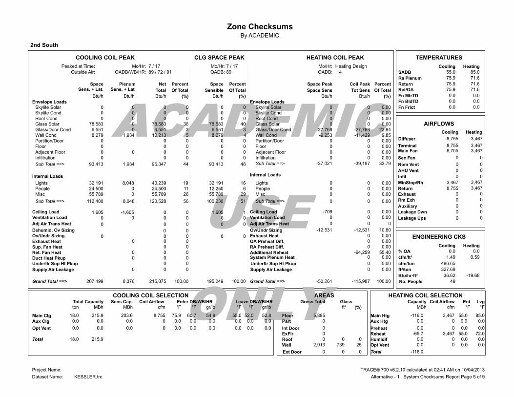
Zone ChecksumsBy ACADEMIC
2nd South
ACADEMIC
USE
ONLY
HEATING COIL PEAKCLG SPACE PEAKCOOLING COIL PEAK TEMPERATURES
Heating DesignMo/Hr:7 / 17Mo/Hr:7 / 17Mo/Hr:Peaked at Time: Cooling Heating
SADBOADB: 14OADB:89 / 72 / 91OADB/WB/HR:Outside Air: 55.0 85.0
Ra Plenum 75.9 71.6
ReturnPercentCoil PeakSpace PeakSpace PercentPercentNetPlenumSpace 75.9 71.6Ret/OASens. + Lat. Of TotalTot SensSpace SensOf TotalSensibleOf TotalTotalSens. + Lat 71.6 75.9
0.0 0.0Fn MtrTDBtu/h (%)Btu/hBtu/h(%)Btu/h(%)Btu/hBtu/h 0.0 0.0Fn BldTDEnvelope Loads 0.0 0.0Fn Frict 0Skylite Solar 0.00 0 0 0 0 0 0 0
0Skylite Cond 0.00 0 0 0 0 0 0 0 0Roof Cond 0.00 0 0 0 0 0 0 0
0.00 78,583Glass Solar 0 0 40 78,583 36 78,583 0 6,551Glass/Door Cond -27,768 23.94-27,768 3 6,551 3 6,551 0
AIRFLOWS
HeatingCooling 8,279Wall Cond 9.85-11,429-9,253 4 8,279 5 10,213 1,934
0Partition/Door 0.00 0 0 0 0 0 0 0Floor 0.00 0 0 0 0 0
Sec Fan 0.00 0Infiltration 0 0 0 0 0 0
3,467 3,467MinStop/Rh
33.79 93,413Sub Total ==> -39,197-37,021 48 93,413 44 95,347 1,934
8,755Return 3,467
Internal Loads
0 0Exhaust
32,191Lights 0.00 0 0 16 32,191 19 40,239 8,048
0 0Rm Exh
24,500People 0.00 0 6 12,250 11
0 0Auxiliary
55,789Misc 0.00 0 0 29 55,789 26 55,789 0
112,480Sub Total ==> 0.00 0 0 51 100,230 56 120,528 8,048
1,605Ceiling Load 0.000-709 1 1,605 0 0-1,605 0Ventilation Load 0.00 0 0 0 0 0 0 0
Sup. Fan Heat 0 0
ENGINEERING CKS
HeatingCooling
Ret. Fan Heat 0 0 0 % OA 0.0 0.0
Duct Heat Pkup 0 0 0 0.59 1.49cfm/ft²
0Ov/Undr Sizing
10.80-12,531-12,531
0 0 0 0
486.65cfm/ton
Exhaust Heat
0.00 0 0 0
327.69ft²/ton
-19.68 36.62Btu/hr·ft²
49No. People 207,499Grand Total ==> 100.00-115,987-50,261100.00 195,249100.00 215,875 8,376
AREAS HEATING COIL SELECTIONCOOLING COIL SELECTIONTotal Capacity Sens Cap. Coil Airflow Enter DB/WB/HR Leave DB/WB/HR Gross Total Glass Coil Airflow Ent LvgCapacityton MBh MBh cfm °F °F gr/lb °F °F gr/lb ft² (%) °F°FcfmMBh
Floor 5,895 Main Htg -116.0 3,467 55.0 85.0 18.0 215.9 203.6 8,755 75.9 60.7 54.9 55.0 52.0 52.8Main ClgPart 0 Aux Htg 0.0 0.0 0.0 0 0.0 0.0 0.0 0 0.0 0.0 0.0 0.0 0.0 0.0Aux Clg
ExFlr 0 0.0Preheat 0.0 0.0 0 0.0 0.0 0.0 0 0.0 0.0 0.0 0.0 0.0 0.0Opt Vent
Roof 0 0 0Reheat -65.7 72.0 55.0 3,467
Wall 2,913 739 25Humidif 0.0 0 0.0 0.0 18.0 215.9TotalOpt Vent 0.0 0.0 0.0 0
-116.0Total
Envelope LoadsSkylite SolarSkylite CondRoof CondGlass SolarGlass/Door CondWall CondPartition/DoorFloor
InfiltrationSub Total ==>
LightsPeopleMisc
Sub Total ==>
Ceiling LoadVentilation Load
System Plenum HeatAdditional Reheat
OA Preheat Diff.
Ov/Undr SizingExhaust Heat
RA Preheat Diff.
Grand Total ==>
Internal Loads
-64,259 0
0 0
0.00
0.00
0.00 55.40
0
Supply Air Leakage
89
Dehumid. Ov Sizing 0 0
Adj Air Trans Heat 0 0 0 0 0 Adj Air Trans Heat 0 0 0Leakage Ups
Leakage Dwn
0 0Infil
AHU Vent
Nom Vent
Main FanTerminal
Adjacent Floor
Diffuser
Supply Air Leakage
Underflr Sup Ht Pkup Underflr Sup Ht Pkup
Adjacent Floor 0 0 0 0
0 0
0 0 0
0 0
0 0 0 0.00
0 0.00
0 0.00
8,755
8,755 8,755
0
0
0
0
0
3,467
3,467 3,467
0
0
0
0
0
0 24,500 0
Int Door 0
Ext Door 0 0 0
TRACE® 700 v6.2.10 calculated at 02:41 AM on 10/04/2013Project Name:
Dataset Name: Alternative - 1 System Checksums Report Page 5 of 9KESSLER.trc

Zone ChecksumsBy ACADEMIC
3rd central
ACADEMIC
USE
ONLY
HEATING COIL PEAKCLG SPACE PEAKCOOLING COIL PEAK TEMPERATURES
Heating DesignMo/Hr:9 / 17Mo/Hr:8 / 17Mo/Hr:Peaked at Time: Cooling Heating
SADBOADB: 14OADB:85 / 72 / 99OADB/WB/HR:Outside Air: 60.1 80.3
Ra Plenum 76.3 68.7
ReturnPercentCoil PeakSpace PeakSpace PercentPercentNetPlenumSpace 76.3 68.7Ret/OASens. + Lat. Of TotalTot SensSpace SensOf TotalSensibleOf TotalTotalSens. + Lat 68.7 76.3
0.0 0.0Fn MtrTDBtu/h (%)Btu/hBtu/h(%)Btu/h(%)Btu/hBtu/h 0.0 0.0Fn BldTDEnvelope Loads 0.0 0.0Fn Frict 0Skylite Solar 0.00 0 0 0 0 0 0 0
0Skylite Cond 0.00 0 0 0 0 0 0 0 0Roof Cond 21.53-35,191 0 0 0 4 16,004 16,004
0.00 147,140Glass Solar 0 0 51 164,626 40 147,140 0 7,926Glass/Door Cond -48,619 29.75-48,619 0-480 2 7,926 0
AIRFLOWS
HeatingCooling 6,874Wall Cond 6.18-10,108-8,270 2 4,911 2 8,455 1,581
0Partition/Door 0.00 0 0 0 0 0 0 0Floor 0.00 0 0 0 0 0
Sec Fan 0.00 0Infiltration 0 0 0 0 0 0
7,271 7,271MinStop/Rh
57.47 161,939Sub Total ==> -93,917-56,888 53 169,056 49 179,525 17,586
19,379Return 7,271
Internal Loads
0 0Exhaust
53,922Lights 0.00 0 0 17 53,922 18 67,402 13,480
0 0Rm Exh
49,000People 0.00 0 8 24,500 13
0 0Auxiliary
71,136Misc 0.00 0 0 22 71,136 19 71,136 0
174,057Sub Total ==> 0.00 0 0 47 149,557 51 187,538 13,480
3,993Ceiling Load 0.000-10,310 1 2,692 0 0-3,993 0Ventilation Load 0.00 0 0 0 0 0 0 0
Sup. Fan Heat 0 0
ENGINEERING CKS
HeatingCooling
Ret. Fan Heat 0 0 0 % OA 0.0 0.0
Duct Heat Pkup 0 0 0 0.74 1.96cfm/ft²
0Ov/Undr Sizing
0.00 0 0
0 0 0 0
633.53cfm/ton
Exhaust Heat
0.00 0 0 0
322.81ft²/ton
-16.55 37.17Btu/hr·ft²
98No. People 339,989Grand Total ==> 100.00-163,428-67,199100.00 321,306100.00 367,063 27,073
AREAS HEATING COIL SELECTIONCOOLING COIL SELECTIONTotal Capacity Sens Cap. Coil Airflow Enter DB/WB/HR Leave DB/WB/HR Gross Total Glass Coil Airflow Ent LvgCapacityton MBh MBh cfm °F °F gr/lb °F °F gr/lb ft² (%) °F°FcfmMBh
Floor 9,874 Main Htg -163.4 7,271 60.1 80.3 30.6 367.1 342.6 19,028 76.3 63.0 64.7 60.1 56.6 62.9Main ClgPart 0 Aux Htg 0.0 0.0 0.0 0 0.0 0.0 0.0 0 0.0 0.0 0.0 0.0 0.0 0.0Aux Clg
ExFlr 0 0.0Preheat 0.0 0.0 0 0.0 0.0 0.0 0 0.0 0.0 0.0 0.0 0.0 0.0Opt Vent
Roof 9,874 0 0Reheat -96.2 72.0 60.1 7,271
Wall 3,235 1,294 40Humidif 0.0 0 0.0 0.0 30.6 367.1TotalOpt Vent 0.0 0.0 0.0 0
-163.4Total
Envelope LoadsSkylite SolarSkylite CondRoof CondGlass SolarGlass/Door CondWall CondPartition/DoorFloor
InfiltrationSub Total ==>
LightsPeopleMisc
Sub Total ==>
Ceiling LoadVentilation Load
System Plenum HeatAdditional Reheat
OA Preheat Diff.
Ov/Undr SizingExhaust Heat
RA Preheat Diff.
Grand Total ==>
Internal Loads
-69,511 0
0 0
0.00
0.00
0.00 42.53
0
Supply Air Leakage
74
Dehumid. Ov Sizing 0 0
Adj Air Trans Heat 0 0 0 0 0 Adj Air Trans Heat 0 0 0Leakage Ups
Leakage Dwn
0 0Infil
AHU Vent
Nom Vent
Main FanTerminal
Adjacent Floor
Diffuser
Supply Air Leakage
Underflr Sup Ht Pkup Underflr Sup Ht Pkup
Adjacent Floor 0 0 0 0
0 0
0 0 0
0 0
0 0 0 0.00
0 0.00
0 0.00
19,379
19,379 19,379
0
0
0
0
0
7,271
7,271 7,271
0
0
0
0
0
0 49,000 0
Int Door 0
Ext Door 0 0 0
TRACE® 700 v6.2.10 calculated at 02:41 AM on 10/04/2013Project Name:
Dataset Name: Alternative - 1 System Checksums Report Page 6 of 9KESSLER.trc
Zone ChecksumsBy ACADEMIC
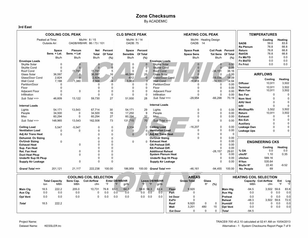
3rd East
ACADEMIC
USE
ONLY
HEATING COIL PEAKCLG SPACE PEAKCOOLING COIL PEAK TEMPERATURES
Heating DesignMo/Hr:9 / 14Mo/Hr:8 / 15Mo/Hr:Peaked at Time: Cooling Heating
SADBOADB: 14OADB:86 / 73 / 101OADB/WB/HR:Outside Air: 59.6 83.8
Ra Plenum 76.8 66.8
ReturnPercentCoil PeakSpace PeakSpace PercentPercentNetPlenumSpace 76.8 66.8Ret/OASens. + Lat. Of TotalTot SensSpace SensOf TotalSensibleOf TotalTotalSens. + Lat 66.8 76.8
0.0 0.0Fn MtrTDBtu/h (%)Btu/hBtu/h(%)Btu/h(%)Btu/hBtu/h 0.0 0.0Fn BldTDEnvelope Loads 0.0 0.0Fn Frict 0Skylite Solar 0.00 0 0 0 0 0 0 0
0Skylite Cond 0.00 0 0 0 0 0 0 0 0Roof Cond 36.16-34,151 0 0 0 5 11,741 11,741
0.00 36,597Glass Solar 0 0 25 46,589 16 36,597 0 2,824Glass/Door Cond -18,036 19.09-18,036 0-612 1 2,824 0
AIRFLOWS
HeatingCooling 7,188Wall Cond 14.94-14,111-11,918 3 5,953 4 8,568 1,380
0Partition/Door 0.00 0 0 0 0 0 0 0Floor 0.00 0 0 0 0 0
Sec Fan 0.00 0Infiltration 0 0 0 0 0 0
3,502 3,502MinStop/Rh
70.19 46,609Sub Total ==> -66,298-29,954 28 51,930 27 59,730 13,122
10,911Return 3,502
Internal Loads
0 0Exhaust
54,171Lights 0.00 0 0 29 54,171 30 67,714 13,543
0 0Rm Exh
34,500People 0.00 0 9 17,250 16
0 0Auxiliary
60,294Misc 0.00 0 0 32 60,294 27 60,294 0
148,965Sub Total ==> 0.00 0 0 70 131,715 73 162,508 13,543
5,547Ceiling Load 0.000-16,207 2 3,314 0 0-5,547 0Ventilation Load 0.00 0 0 0 0 0 0 0
Sup. Fan Heat 0 0
ENGINEERING CKS
HeatingCooling
Ret. Fan Heat 0 0 0 % OA 0.0 0.0
Duct Heat Pkup 0 0 0 0.35 1.10cfm/ft²
0Ov/Undr Sizing
0.00 0 0
0 0 0 0
589.16cfm/ton
Exhaust Heat
0.00 0 0 0
535.64ft²/ton
-9.52 22.40Btu/hr·ft²
69No. People 201,121Grand Total ==> 100.00-94,455-46,161100.00 186,959100.00 222,238 21,117
AREAS HEATING COIL SELECTIONCOOLING COIL SELECTIONTotal Capacity Sens Cap. Coil Airflow Enter DB/WB/HR Leave DB/WB/HR Gross Total Glass Coil Airflow Ent LvgCapacityton MBh MBh cfm °F °F gr/lb °F °F gr/lb ft² (%) °F°FcfmMBh
Floor 9,920 Main Htg -94.5 3,502 59.6 83.8 18.5 222.2 205.0 10,731 76.8 63.1 64.7 59.6 56.3 62.4Main ClgPart 0 Aux Htg 0.0 0.0 0.0 0 0.0 0.0 0.0 0 0.0 0.0 0.0 0.0 0.0 0.0Aux Clg
ExFlr 0 0.0Preheat 0.0 0.0 0 0.0 0.0 0.0 0 0.0 0.0 0.0 0.0 0.0 0.0Opt Vent
Roof 9,920 0 0Reheat -48.3 72.0 59.6 3,502
Wall 3,201 480 15Humidif 0.0 0 0.0 0.0 18.5 222.2TotalOpt Vent 0.0 0.0 0.0 0
-94.5Total
Envelope LoadsSkylite SolarSkylite CondRoof CondGlass SolarGlass/Door CondWall CondPartition/DoorFloor
InfiltrationSub Total ==>
LightsPeopleMisc
Sub Total ==>
Ceiling LoadVentilation Load
System Plenum HeatAdditional Reheat
OA Preheat Diff.
Ov/Undr SizingExhaust Heat
RA Preheat Diff.
Grand Total ==>
Internal Loads
-28,157 0
0 0
0.00
0.00
0.00 29.81
0
Supply Air Leakage
75
Dehumid. Ov Sizing 0 0
Adj Air Trans Heat 0 0 0 0 0 Adj Air Trans Heat 0 0 0Leakage Ups
Leakage Dwn
0 0Infil
AHU Vent
Nom Vent
Main FanTerminal
Adjacent Floor
Diffuser
Supply Air Leakage
Underflr Sup Ht Pkup Underflr Sup Ht Pkup
Adjacent Floor 0 0 0 0
0 0
0 0 0
0 0
0 0 0 0.00
0 0.00
0 0.00
10,911
10,911 10,911
0
0
0
0
0
3,502
3,502 3,502
0
0
0
0
0
0 34,500 0
Int Door 0
Ext Door 0 0 0
TRACE® 700 v6.2.10 calculated at 02:41 AM on 10/04/2013Project Name:
Dataset Name: Alternative - 1 System Checksums Report Page 7 of 9KESSLER.trc

Zone ChecksumsBy ACADEMIC
3rd North
ACADEMIC
USE
ONLY
HEATING COIL PEAKCLG SPACE PEAKCOOLING COIL PEAK TEMPERATURES
Heating DesignMo/Hr:7 / 18Mo/Hr:7 / 18Mo/Hr:Peaked at Time: Cooling Heating
SADBOADB: 14OADB:87 / 71 / 88OADB/WB/HR:Outside Air: 60.7 83.1
Ra Plenum 76.8 67.8
ReturnPercentCoil PeakSpace PeakSpace PercentPercentNetPlenumSpace 76.8 67.8Ret/OASens. + Lat. Of TotalTot SensSpace SensOf TotalSensibleOf TotalTotalSens. + Lat 67.8 76.8
0.0 0.0Fn MtrTDBtu/h (%)Btu/hBtu/h(%)Btu/h(%)Btu/hBtu/h 0.0 0.0Fn BldTDEnvelope Loads 0.0 0.0Fn Frict 0Skylite Solar 0.00 0 0 0 0 0 0 0
0Skylite Cond 0.00 0 0 0 0 0 0 0 0Roof Cond 26.94-16,616 0 0 0 7 10,563 10,563
0.00 43,909Glass Solar 0 0 35 43,909 30 43,909 0 3,799Glass/Door Cond -17,228 27.93-17,228 3 3,799 3 3,799 0
AIRFLOWS
HeatingCooling 5,706Wall Cond 13.64-8,416-6,967 5 5,706 5 6,945 1,239
0Partition/Door 0.00 0 0 0 0 0 0 0Floor 0.00 0 0 0 0 0
Sec Fan 0.00 0Infiltration 0 0 0 0 0 0
2,464 2,464MinStop/Rh
68.51 53,414Sub Total ==> -42,260-24,195 43 53,414 44 65,215 11,802
7,811Return 2,464
Internal Loads
0 0Exhaust
25,912Lights 0.00 0 0 21 25,912 22 32,389 6,478
0 0Rm Exh
15,000People 0.00 0 6 7,500 10
0 0Auxiliary
35,222Misc 0.00 0 0 28 35,222 24 35,222 0
76,134Sub Total ==> 0.00 0 0 55 68,634 56 82,612 6,478
2,693Ceiling Load 0.000-6,389 2 2,693 0 0-2,693 0Ventilation Load 0.00 0 0 0 0 0 0 0
Sup. Fan Heat 0 0
ENGINEERING CKS
HeatingCooling
Ret. Fan Heat 0 0 0 % OA 0.0 0.0
Duct Heat Pkup 0 0 0 0.52 1.65cfm/ft²
0Ov/Undr Sizing
0.00 0 0
0 0 0 0
634.06cfm/ton
Exhaust Heat
0.00 0 0 0
385.18ft²/ton
-13.00 31.15Btu/hr·ft²
30No. People 132,240Grand Total ==> 100.00-61,687-30,585100.00 124,740100.00 147,827 15,587
AREAS HEATING COIL SELECTIONCOOLING COIL SELECTIONTotal Capacity Sens Cap. Coil Airflow Enter DB/WB/HR Leave DB/WB/HR Gross Total Glass Coil Airflow Ent LvgCapacityton MBh MBh cfm °F °F gr/lb °F °F gr/lb ft² (%) °F°FcfmMBh
Floor 4,745 Main Htg -61.7 2,464 60.7 83.1 12.3 147.8 140.3 7,811 76.8 63.1 64.7 60.7 56.9 63.4Main ClgPart 0 Aux Htg 0.0 0.0 0.0 0 0.0 0.0 0.0 0 0.0 0.0 0.0 0.0 0.0 0.0Aux Clg
ExFlr 0 0.0Preheat 0.0 0.0 0 0.0 0.0 0.0 0 0.0 0.0 0.0 0.0 0.0 0.0Opt Vent
Roof 4,745 0 0Reheat -31.1 72.0 60.7 2,464
Wall 2,079 459 22Humidif 0.0 0 0.0 0.0 12.3 147.8TotalOpt Vent 0.0 0.0 0.0 0
-61.7Total
Envelope LoadsSkylite SolarSkylite CondRoof CondGlass SolarGlass/Door CondWall CondPartition/DoorFloor
InfiltrationSub Total ==>
LightsPeopleMisc
Sub Total ==>
Ceiling LoadVentilation Load
System Plenum HeatAdditional Reheat
OA Preheat Diff.
Ov/Undr SizingExhaust Heat
RA Preheat Diff.
Grand Total ==>
Internal Loads
-19,427 0
0 0
0.00
0.00
0.00 31.49
0
Supply Air Leakage
87
Dehumid. Ov Sizing 0 0
Adj Air Trans Heat 0 0 0 0 0 Adj Air Trans Heat 0 0 0Leakage Ups
Leakage Dwn
0 0Infil
AHU Vent
Nom Vent
Main FanTerminal
Adjacent Floor
Diffuser
Supply Air Leakage
Underflr Sup Ht Pkup Underflr Sup Ht Pkup
Adjacent Floor 0 0 0 0
0 0
0 0 0
0 0
0 0 0 0.00
0 0.00
0 0.00
7,811
7,811 7,811
0
0
0
0
0
2,464
2,464 2,464
0
0
0
0
0
0 15,000 0
Int Door 0
Ext Door 0 0 0
TRACE® 700 v6.2.10 calculated at 02:41 AM on 10/04/2013Project Name:
Dataset Name: Alternative - 1 System Checksums Report Page 8 of 9KESSLER.trc

Zone ChecksumsBy ACADEMIC
3rd South
ACADEMIC
USE
ONLY
HEATING COIL PEAKCLG SPACE PEAKCOOLING COIL PEAK TEMPERATURES
Heating DesignMo/Hr:7 / 18Mo/Hr:7 / 18Mo/Hr:Peaked at Time: Cooling Heating
SADBOADB: 14OADB:87 / 71 / 88OADB/WB/HR:Outside Air: 60.4 81.1
Ra Plenum 76.6 68.6
ReturnPercentCoil PeakSpace PeakSpace PercentPercentNetPlenumSpace 76.6 68.6Ret/OASens. + Lat. Of TotalTot SensSpace SensOf TotalSensibleOf TotalTotalSens. + Lat 68.6 76.6
0.0 0.0Fn MtrTDBtu/h (%)Btu/hBtu/h(%)Btu/h(%)Btu/hBtu/h 0.0 0.0Fn BldTDEnvelope Loads 0.0 0.0Fn Frict 0Skylite Solar 0.00 0 0 0 0 0 0 0
0Skylite Cond 0.00 0 0 0 0 0 0 0 0Roof Cond 21.00-20,995 0 0 0 6 13,246 13,246
0.00 65,387Glass Solar 0 0 36 65,387 30 65,387 0 6,134Glass/Door Cond -27,805 27.81-27,805 3 6,134 3 6,134 0
AIRFLOWS
HeatingCooling 7,985Wall Cond 11.84-11,841-9,708 4 7,985 5 9,792 1,808
0Partition/Door 0.00 0 0 0 0 0 0 0Floor 0.00 0 0 0 0 0
Sec Fan 0.00 0Infiltration 0 0 0 0 0 0
4,345 4,345MinStop/Rh
60.65 79,505Sub Total ==> -60,641-37,513 43 79,505 44 94,559 15,053
11,260Return 4,345
Internal Loads
0 0Exhaust
32,257Lights 0.00 0 0 18 32,257 19 40,321 8,064
0 0Rm Exh
24,500People 0.00 0 7 12,250 11
0 0Auxiliary
55,823Misc 0.00 0 0 31 55,823 26 55,823 0
112,580Sub Total ==> 0.00 0 0 55 100,330 56 120,644 8,064
2,999Ceiling Load 0.000-6,444 2 2,999 0 0-2,999 0Ventilation Load 0.00 0 0 0 0 0 0 0
Sup. Fan Heat 0 0
ENGINEERING CKS
HeatingCooling
Ret. Fan Heat 0 0 0 % OA 0.0 0.0
Duct Heat Pkup 0 0 0 0.74 1.91cfm/ft²
0Ov/Undr Sizing
0.00 0 0
0 0 0 0
627.87cfm/ton
Exhaust Heat
0.00 0 0 0
329.38ft²/ton
-16.93 36.43Btu/hr·ft²
49No. People 195,085Grand Total ==> 100.00-99,980-43,958100.00 182,835100.00 215,203 20,118
AREAS HEATING COIL SELECTIONCOOLING COIL SELECTIONTotal Capacity Sens Cap. Coil Airflow Enter DB/WB/HR Leave DB/WB/HR Gross Total Glass Coil Airflow Ent LvgCapacityton MBh MBh cfm °F °F gr/lb °F °F gr/lb ft² (%) °F°FcfmMBh
Floor 5,907 Main Htg -100.0 4,345 60.4 81.1 17.9 215.2 203.0 11,260 76.6 63.1 64.7 60.4 56.8 63.2Main ClgPart 0 Aux Htg 0.0 0.0 0.0 0 0.0 0.0 0.0 0 0.0 0.0 0.0 0.0 0.0 0.0Aux Clg
ExFlr 0 0.0Preheat 0.0 0.0 0 0.0 0.0 0.0 0 0.0 0.0 0.0 0.0 0.0 0.0Opt Vent
Roof 5,907 0 0Reheat -56.0 72.0 60.4 4,345
Wall 3,015 740 25Humidif 0.0 0 0.0 0.0 17.9 215.2TotalOpt Vent 0.0 0.0 0.0 0
-100.0Total
Envelope LoadsSkylite SolarSkylite CondRoof CondGlass SolarGlass/Door CondWall CondPartition/DoorFloor
InfiltrationSub Total ==>
LightsPeopleMisc
Sub Total ==>
Ceiling LoadVentilation Load
System Plenum HeatAdditional Reheat
OA Preheat Diff.
Ov/Undr SizingExhaust Heat
RA Preheat Diff.
Grand Total ==>
Internal Loads
-39,339 0
0 0
0.00
0.00
0.00 39.35
0
Supply Air Leakage
87
Dehumid. Ov Sizing 0 0
Adj Air Trans Heat 0 0 0 0 0 Adj Air Trans Heat 0 0 0Leakage Ups
Leakage Dwn
0 0Infil
AHU Vent
Nom Vent
Main FanTerminal
Adjacent Floor
Diffuser
Supply Air Leakage
Underflr Sup Ht Pkup Underflr Sup Ht Pkup
Adjacent Floor 0 0 0 0
0 0
0 0 0
0 0
0 0 0 0.00
0 0.00
0 0.00
11,260
11,260 11,260
0
0
0
0
0
4,345
4,345 4,345
0
0
0
0
0
0 24,500 0
Int Door 0
Ext Door 0 0 0
TRACE® 700 v6.2.10 calculated at 02:41 AM on 10/04/2013Project Name:
Dataset Name: Alternative - 1 System Checksums Report Page 9 of 9KESSLER.trc