Embed Size (px)
Citation preview
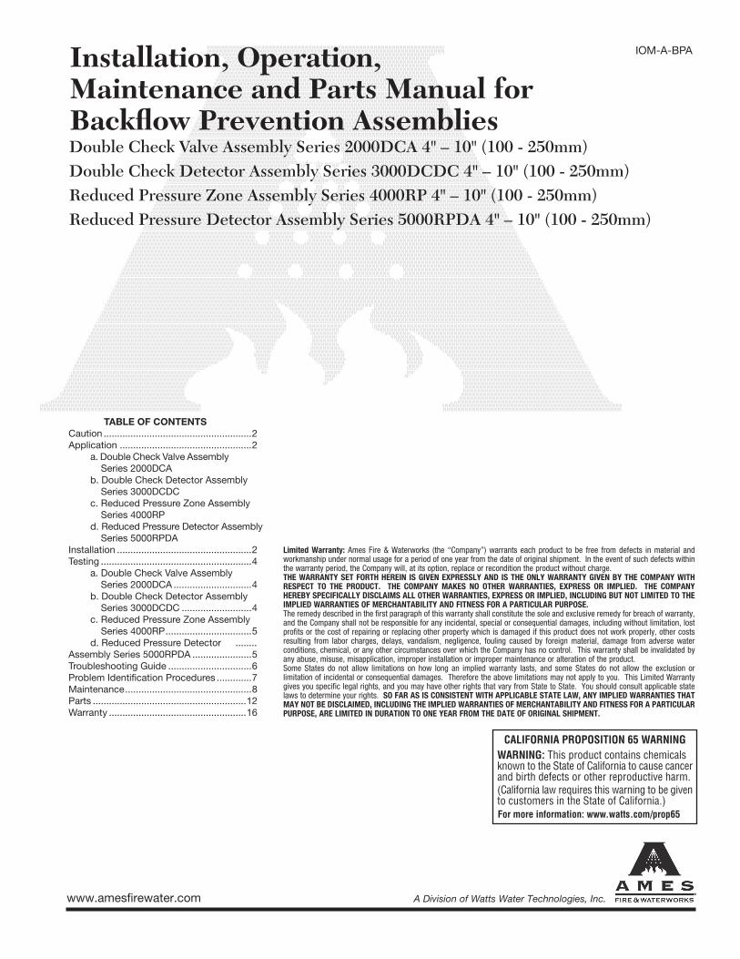
Installation, Operation, Maintenance and Parts Manual for Backfl ow Prevention AssembliesDouble Check Valve Assembly Series 2000DCA 4" – 10" (100 - 250mm)Double Check Detector Assembly Series 3000DCDC 4" – 10" (100 - 250mm)Reduced Pressure Zone Assembly Series 4000RP 4" – 10" (100 - 250mm)Reduced Pressure Detector Assembly Series 5000RPDA 4" – 10" (100 - 250mm)
TABLE OF CONTENTS
Caution .......................................................2
Application .................................................2
a. Double Check Valve Assembly
Series 2000DCA
b. Double Check Detector Assembly
Series 3000DCDC
c. Reduced Pressure Zone Assembly
Series 4000RP
d. Reduced Pressure Detector Assembly
Series 5000RPDA
Installation ..................................................2
Testing ........................................................4
a. Double Check Valve Assembly
Series 2000DCA .............................4
b. Double Check Detector Assembly
Series 3000DCDC ..........................4
c. Reduced Pressure Zone Assembly
Series 4000RP ................................5
d. Reduced Pressure Detector ........
Assembly Series 5000RPDA ......................5
Troubleshooting Guide ...............................6
Problem Identifi cation Procedures .............7
Maintenance ...............................................8
Parts .........................................................12
Warranty ...................................................16
IOM-A-BPA
Limited Warranty: Ames Fire & Waterworks (the “Company”) warrants each product to be free from defects in material and workmanship under normal usage for a period of one year from the date of original shipment. In the event of such defects within the warranty period, the Company will, at its option, replace or recondition the product without charge. THE WARRANTY SET FORTH HEREIN IS GIVEN EXPRESSLY AND IS THE ONLY WARRANTY GIVEN BY THE COMPANY WITH RESPECT TO THE PRODUCT. THE COMPANY MAKES NO OTHER WARRANTIES, EXPRESS OR IMPLIED. THE COMPANY HEREBY SPECIFICALLY DISCLAIMS ALL OTHER WARRANTIES, EXPRESS OR IMPLIED, INCLUDING BUT NOT LIMITED TO THE IMPLIED WARRANTIES OF MERCHANTABILITY AND FITNESS FOR A PARTICULAR PURPOSE.The remedy described in the first paragraph of this warranty shall constitute the sole and exclusive remedy for breach of warranty, and the Company shall not be responsible for any incidental, special or consequential damages, including without limitation, lost profits or the cost of repairing or replacing other property which is damaged if this product does not work properly, other costs resulting from labor charges, delays, vandalism, negligence, fouling caused by foreign material, damage from adverse water conditions, chemical, or any other circumstances over which the Company has no control. This warranty shall be invalidated by any abuse, misuse, misapplication, improper installation or improper maintenance or alteration of the product. Some States do not allow limitations on how long an implied warranty lasts, and some States do not allow the exclusion or limitation of incidental or consequential damages. Therefore the above limitations may not apply to you. This Limited Warranty gives you specific legal rights, and you may have other rights that vary from State to State. You should consult applicable state laws to determine your rights. SO FAR AS IS CONSISTENT WITH APPLICABLE STATE LAW, ANY IMPLIED WARRANTIES THAT MAY NOT BE DISCLAIMED, INCLUDING THE IMPLIED WARRANTIES OF MERCHANTABILITY AND FITNESS FOR A PARTICULAR PURPOSE, ARE LIMITED IN DURATION TO ONE YEAR FROM THE DATE OF ORIGINAL SHIPMENT.
www.amesfirewater.com A Division of Watts Water Technologies, Inc.
2
INSTALLATION, OPERATION AND MAINTENANCE MANUALDOUBLE CHECK VALVE ASSEMBLY, DOUBLE CHECK DETECTOR ASSEMBLY, REDUCED PRESSURE ZONE ASSEMBLY, AND REDUCED PRESSURE DETECTOR ASSEM-
CAUTION:
The installation and maintenance of any Ames back-fl ow prevention assembly should be performed by a qualifi ed licensed technician. Failure to do so may result in a malfunctioning assembly. All instructions should be read thoroughly by the technician before installation or performing any maintenance on the assembly.
All Ames assemblies are tested at the factory for proper operation. Any damage or improper operation
caused by debris in pipeline or improper installation is not included in this warranty coverage. If a malfunc-tion occurs or a possible warranty situation exists, follow the instructions in the maintenance manual to correct the problem. CONTACT YOUR LOCAL AMES REPRESENTATIVE.
APPLICATION:
INSTALLATION INSTRUCTIONS:
Before any Ames backfl ow assembly is installed, care should be taken to be sure the correct assembly is be-ing used in the proper application. Consult your local authority to determine proper device and position for the application.
A. SERIES 2000DCA
Series 2000DCA (Double Check Valve Assembly) is used to prevent backfl ow of aesthetically objectionable but not toxic contaminants into the main water supply. The assembly consists of two independently operating internally spring loaded check valves, two shutoff valves and four test cocks.
B. SERIES 3000DCDC
Series 3000DCDC (Double Check Detector Assembly) is used on fi re lines to prevent backfl ow of aesthetically objectionable but not toxic contaminants into the main water supply. It also detects minimal water movement in the fi re line system from water theft or water leakage.
The bypass assembly consists of a water meter in series with a double check valve assembly.
C. SERIES 4000RP
Series 4000RP (Reduced Pressure Zone Assembly) is for use on potable water lines where a health hazard could exist in the event of a backfl ow situation. The as-sembly consists of two independently operating swing check valves with an independent hydraulically operated differential pressure relief valve, two shutoff valves, and four test cocks.
D. SERIES 5000RPDA
Series 5000RPDA (Reduced Pressure Detector Assem-bly) is used on fi relines where a health hazard could exist in the event of a backfl ow situation. It also detects any minor water movement in the fi reline system from water theft or water leakage. The bypass assembly consists of a water meter in series with a reduced pressure zone assembly.
A. Before installing any Ames backfl ow assembly, fl ush the lines thoroughly to remove all debris, chips and other foreign objects, failure to do so may make the assembly inoperable.
B. Double Check Valve Assemblies and Double Check Detector Assemblies may be placed in any position as long as the fl ow indicator arrow on the valve is pointed in the direction of water fl ow, and the local authority has approved installation confi guration. RP assemblies are approved by national approval agencies to be installed in a horizontal position. Any other installation confi gura-tions must be approved by local authorities.
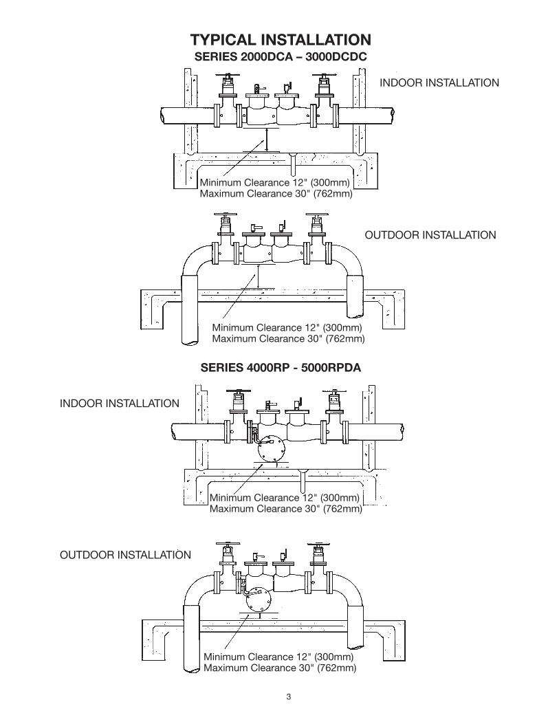
C. Allow suffi cient clearance around the installed assem-bly to conduct testing, servicing and inspection. Allow a minimum of 12" from the fl ood level to the bottom of the assembly.
D. If the double check valve or double check detector assembly is installed in a vault or pit be sure proper drain-age is available. If suffi cient drainage is not available a cross-connection may occur. The RP assembly shall not be installed in a vault or pit.
3
TYPICAL INSTALLATIONSERIES 2000DCA – 3000DCDC
SERIES 4000RP - 5000RPDA
INDOOR INSTALLATION
OUTDOOR INSTALLATION
INDOOR INSTALLATION
OUTDOOR INSTALLATION
Minimum Clearance 12" (300mm)Maximum Clearance 30" (762mm)
Minimum Clearance 12" (300mm)Maximum Clearance 30" (762mm)
Minimum Clearance 12" (300mm)Maximum Clearance 30" (762mm)
Minimum Clearance 12" (300mm)Maximum Clearance 30" (762mm)
4
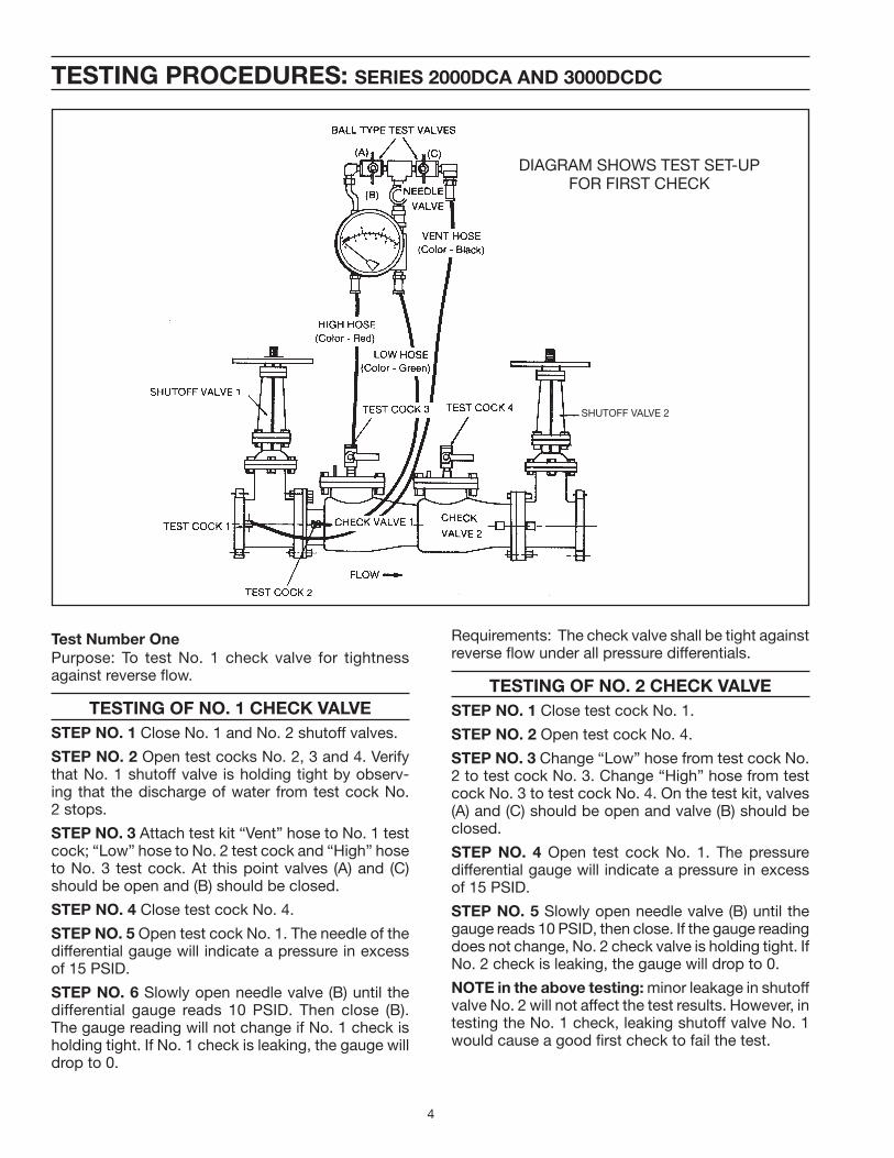
TESTING PROCEDURES: SERIES 2000DCA AND 3000DCDC
DIAGRAM SHOWS TEST SET-UPFOR FIRST CHECK
SHUTOFF VALVE 2
Test Number One
Purpose: To test No. 1 check valve for tightness against reverse fl ow.
TESTING OF NO. 1 CHECK VALVE
STEP NO. 1 Close No. 1 and No. 2 shutoff valves.
STEP NO. 2 Open test cocks No. 2, 3 and 4. Verify that No. 1 shutoff valve is holding tight by observ-ing that the discharge of water from test cock No. 2 stops.
STEP NO. 3 Attach test kit “Vent” hose to No. 1 test cock; “Low” hose to No. 2 test cock and “High” hose to No. 3 test cock. At this point valves (A) and (C) should be open and (B) should be closed.
STEP NO. 4 Close test cock No. 4.
STEP NO. 5 Open test cock No. 1. The needle of the differential gauge will indicate a pressure in excess of 15 PSID.
STEP NO. 6 Slowly open needle valve (B) until the differential gauge reads 10 PSID. Then close (B). The gauge reading will not change if No. 1 check is holding tight. If No. 1 check is leaking, the gauge will drop to 0.
Requirements: The check valve shall be tight against reverse fl ow under all pressure differentials.
TESTING OF NO. 2 CHECK VALVE
STEP NO. 1 Close test cock No. 1.
STEP NO. 2 Open test cock No. 4.
STEP NO. 3 Change “Low” hose from test cock No. 2 to test cock No. 3. Change “High” hose from test cock No. 3 to test cock No. 4. On the test kit, valves (A) and (C) should be open and valve (B) should be closed.
STEP NO. 4 Open test cock No. 1. The pressure differential gauge will indicate a pressure in excess of 15 PSID.
STEP NO. 5 Slowly open needle valve (B) until the gauge reads 10 PSID, then close. If the gauge reading does not change, No. 2 check valve is holding tight. If No. 2 check is leaking, the gauge will drop to 0.
NOTE in the above testing: minor leakage in shutoff valve No. 2 will not affect the test results. However, in testing the No. 1 check, leaking shutoff valve No. 1 would cause a good fi rst check to fail the test.
5
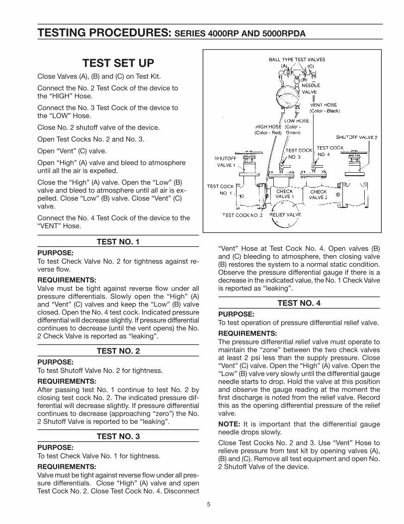
TESTING PROCEDURES: SERIES 4000RP AND 5000RPDA
TEST SET UPClose Valves (A), (B) and (C) on Test Kit.
Connect the No. 2 Test Cock of the device tothe “HIGH” Hose.
Connect the No. 3 Test Cock of the device tothe “LOW” Hose.
Close No. 2 shutoff valve of the device.
Open Test Cocks No. 2 and No. 3.
Open “Vent” (C) valve.
Open “High” (A) valve and bleed to atmosphere until all the air is expelled.
Close the “High” (A) valve. Open the “Low” (B) valve and bleed to atmosphere until all air is ex-pelled. Close “Low” (B) valve. Close “Vent” (C) valve.
Connect the No. 4 Test Cock of the device to the “VENT” Hose.
TEST NO. 1
PURPOSE:
To test Check Valve No. 2 for tightness against re-verse fl ow.
REQUIREMENTS:
Valve must be tight against reverse fl ow under all pressure differentials. Slowly open the “High” (A) and “Vent” (C) valves and keep the “Low” (B) valve closed. Open the No. 4 test cock. Indicated pressure differential will decrease slightly. If pressure differential continues to decrease (until the vent opens) the No. 2 Check Valve is reported as “leaking”.
TEST NO. 2
PURPOSE:
To test Shutoff Valve No. 2 for tightness.
REQUIREMENTS:
After passing test No. 1 continue to test No. 2 by closing test cock No. 2. The indicated pressure dif-ferential will decrease slightly. If pressure differential continues to decrease (approaching “zero”) the No. 2 Shutoff Valve is reported to be “leaking”.
TEST NO. 3
PURPOSE:
To test Check Valve No. 1 for tightness.
REQUIREMENTS:
Valve must be tight against reverse fl ow under all pres-sure differentials. Close “High” (A) valve and open Test Cock No. 2. Close Test Cock No. 4. Disconnect
“Vent” Hose at Test Cock No. 4. Open valves (B) and (C) bleeding to atmosphere, then closing valve (B) restores the system to a normal static condition. Observe the pressure differential gauge if there is a decrease in the indicated value, the No. 1 Check Valve is reported as “leaking”.
TEST NO. 4
PURPOSE:
To test operation of pressure differential relief valve.
REQUIREMENTS:
The pressure differential relief valve must operate to maintain the “zone” between the two check valves at least 2 psi less than the supply pressure. Close “Vent” (C) valve. Open the “High” (A) valve. Open the “Low” (B) valve very slowly until the differential gauge needle starts to drop. Hold the valve at this position and observe the gauge reading at the moment the fi rst discharge is noted from the relief valve. Record this as the opening differential pressure of the relief valve.
NOTE: It is important that the differential gauge needle drops slowly.
Close Test Cocks No. 2 and 3. Use “Vent” Hose to relieve pressure from test kit by opening valves (A), (B) and (C). Remove all test equipment and open No. 2 Shutoff Valve of the device.
6
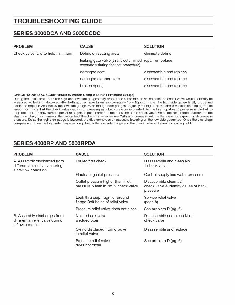
TROUBLESHOOTING GUIDE
SERIES 2000DCA AND 3000DCDC
PROBLEM CAUSE SOLUTION
Check valve fails to hold minimum Debris on seating area eliminate debris
leaking gate valve (this is determined repair or replace separately during the test procedure)
damaged seat disassemble and replace
damaged clapper plate disassemble and replace
broken spring disassemble and replace
CHECK VALVE DISC COMPRESSION (When Using A Duplex Pressure Gauge)
During the ‘initial test’, both the high and low side gauges may drop at the same rate, in which case the check valve would normally be assessed as leaking. However, after both gauges have fallen approximately 10 – 15psi or more, the high side gauge fi nally drops and holds the required 2psi below the low side gauge. Even though both gauges originally fell together, the check valve is holding tight. The reason for this is that the check valve disc is compressing as a backpressure is created. As the high (upstream) pressure is bled off to drop the 2psi, the downstream pressure begins to push harder on the backside of the check valve. So as the seat imbeds further into the elastomer disc, the volume on the backside of the check valve increases. With an increase in volume there is a corresponding decrease in pressure. So as the high side gauge is lowered, the disc compression causes a lowering on the low side gauge too. Once the disc stops compressing, then the high side gauge will drop below the low side gauge and the check valve will show as holding tight.
SERIES 4000RP AND 5000RPDA
PROBLEM CAUSE SOLUTION
A. Assembly discharged from Fouled fi rst check Disassemble and clean No.differential relief valve during 1 check valvea no-fl ow condition Fluctuating inlet pressure Control supply line water pressure
Outlet pressure higher than inlet Disassemble clean #2 pressure & leak in No. 2 check valve check valve & identify cause of back pressure
Leak thru diaphragm or around Service relief valve fl ange Bolt holes of relief valve (page 8)
Pressure relief valve-does not close See problem D (pg. 6)
B. Assembly discharges from No. 1 check valve Disassemble and clean No. 1differential relief valve during wedged open check valvea fl ow condition O-ring displaced from groove Disassemble and replace in relief valve
Pressure relief valve - See problem D (pg. 6) does not close
7
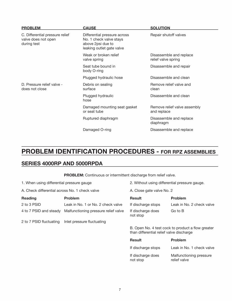
PROBLEM CAUSE SOLUTION
C. Differential pressure relief Differential pressure across Repair shutoff valvesvalve does not open No. 1 check valve staysduring test above 2psi due to leaking outlet gate valve
Weak or broken relief Disassemble and replace valve spring relief valve spring
Seat tube bound in Disassemble and repair body O-ring
Plugged hydraulic hose Disassemble and clean
D. Pressure relief valve - Debris on sealing Remove relief valve anddoes not close surface clean
Plugged hydraulic Disassemble and clean hose
Damaged mounting seat gasket Remove relief valve assembly or seat tube and replace
Ruptured diaphragm Disassemble and replace diaphragm
Damaged O-ring Disassemble and replace
PROBLEM IDENTIFICATION PROCEDURES - FOR RPZ ASSEMBLIES
SERIES 4000RP AND 5000RPDA
PROBLEM: Continuous or intermittent discharge from relief valve.
1. When using differential pressure gauge 2. Without using differential pressure gauge.
A. Check differential across No. 1 check valve A. Close gate valve No. 2
Reading Problem Result Problem
2 to 3 PSID Leak in No. 1 or No. 2 check valve If discharge stops Leak in No. 2 check valve
4 to 7 PSID and steady Malfunctioning pressure relief valve If discharge does Go to B not stop
2 to 7 PSID fl uctuating Inlet pressure fl uctuating
B. Open No. 4 test cock to product a fl ow greater than differential relief valve discharge
Result Problem
If discharge stops Leak in No. 1 check valve
If discharge does Malfunctioning pressure not stop relief valve
8
DRAWING I
RETAINER CLIP
SEAT OUTER LINK
INNER LINK
DRAWING II
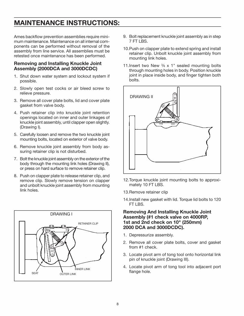
MAINTENANCE INSTRUCTIONS:
Ames backfl ow prevention assemblies require mini-mum maintenance. Maintenance on all internal com-ponents can be performed without removal of the assembly from line service. All assemblies must be retested once maintenance has been performed.
Removing and Installing Knuckle JointAssembly (2000DCA and 3000DCDC)
1. Shut down water system and lockout system if possible.
2. Slowly open test cocks or air bleed screw to relieve pressure.
3. Remove all cover plate bolts, lid and cover plate gasket from valve body.
4. Push retainer clip into knuckle joint retention openings located on inner and outer linkages of knuckle joint assembly, until clapper open slightly. (Drawing I).
5. Carefully loosen and remove the two knuckle joint mounting bolts, located on exterior of valve body.
6. Remove knuckle joint assembly from body as-suring retainer clip is not disturbed.
7. Bolt the knuckle joint assembly on the exterior of the body through the mounting link holes (Drawing II), or press on hard surface to remove retainer clip.
8. Push on clapper plate to release retainer clip, and remove clip. Slowly remove tension on clapper and unbolt knuckle joint assembly from mounting link holes.
9. Bolt replacement knuckle joint assembly as in step 7 FT LBS.
10. Push on clapper plate to extend spring and install retainer clip. Unbolt knuckle joint assembly from mounting link holes.
11. Insert two New 3⁄8 x 1" sealed mounting bolts through mounting holes in body. Position knuckle joint in place inside body, and fi nger tighten both bolts.
12. Torque knuckle joint mounting bolts to approxi-mately 10 FT LBS.
13. Remove retainer clip
14. Install new gasket with lid. Torque lid bolts to 120 FT LBS.
Removing And Installing Knuckle JointAssembly (#1 check valve on 4000RP,1st and 2nd check on 10" (250mm)2000 DCA and 3000DCDC).
1. Depressurize assembly.
2. Remove all cover plate bolts, cover and gasket from #1 check.
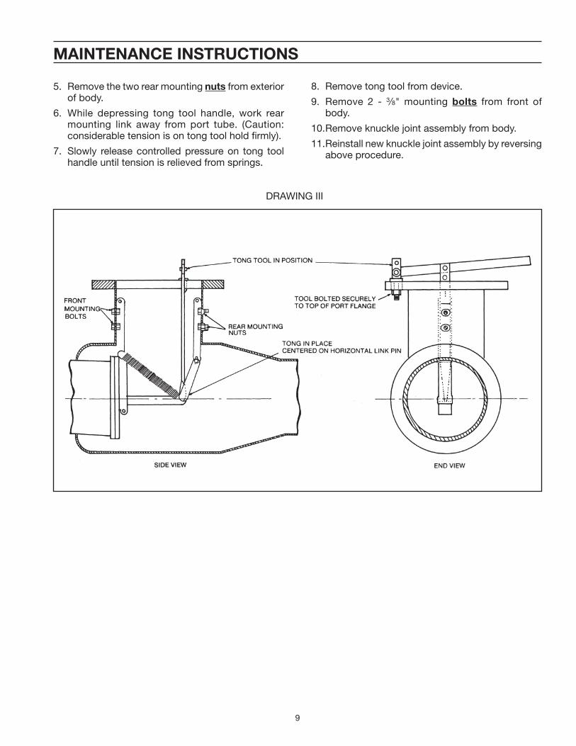
3. Locate pivot arm of tong tool onto horizontal link pin of knuckle joint (Drawing III).
4. Locate pivot arm of tong tool into adjacent port fl ange hole.
9
MAINTENANCE INSTRUCTIONS
5. Remove the two rear mounting nuts from exterior of body.
6. While depressing tong tool handle, work rear mounting link away from port tube. (Caution: considerable tension is on tong tool hold fi rmly).
7. Slowly release controlled pressure on tong tool handle until tension is relieved from springs.
8. Remove tong tool from device.
9. Remove 2 - 3⁄8" mounting bolts from front of body.
10. Remove knuckle joint assembly from body.
11. Reinstall new knuckle joint assembly by reversing above procedure.
DRAWING III
10
MAINTENANCE INSTRUCTIONS:
REMOVAL AND REPAIR OF RELIEF VALVE (See Drawing Page 15)
DRAWING IV
1. Depressurize assembly. Disconnect hose and re-move relief valve from elbow fl ange. Inspect rubber relief valve mounting seat gasket for debris, cutting or distortion of rubber. Remove 5/16" lid bolts.
2. Disassemble piston assembly by unscrewing top diaphragm plate from seat tube in counter clockwise direction. Remove O-ring from relief valve body. Clean and inspect all parts for damage, debris or buildup. Clean and inspect vent hole in seat tube and O-ring groove in body.
3. Place small amount of FDA approved lubricant on O-ring groove, seat tube OD, O-ring guide pin and diaphragm plate threads. (Do not use petroleum or solvent based lubricant). Clean O-ring groove on top washer plate. Hold top washer plate with threaded side up. Set diaphragm on washer plate with side marked HIGH PRESSURE SIDE down, install bottom washer plate with spring guide shoulder away from diaphragm. Set seat tube on threaded stub of washer plate and slowly engage threads. Hand tighten seat tube in clockwise direction.
4. Stretch to 3" diameter and lubricate O-ring and place in O-ring groove. Place relief valve spring in body. Place lid with bolts on piston assembly and thread diaphragm over bolts. Ensure that diaphragm is not pinched between lid and washer plate. Reas-semble unit assuring spring is seated over guide and that tube is carefully pushed through O-ring in body. Hand tighten bolts. If O-ring has been pushed from groove, disassemble, inspect for damage, and repeat assembly.
Clean and place rubber seat mounting gasket in recess with raised O-ring side out. Before installing relief valve, slightly open #1 gate valve to ensure hose if free of debris and debris is washed from main body. Bolt relief valve to mainline valve and install hose. Open #1 gate valve and bleed air from all test cocks and air vents on relief valve.
5. Test assembly.
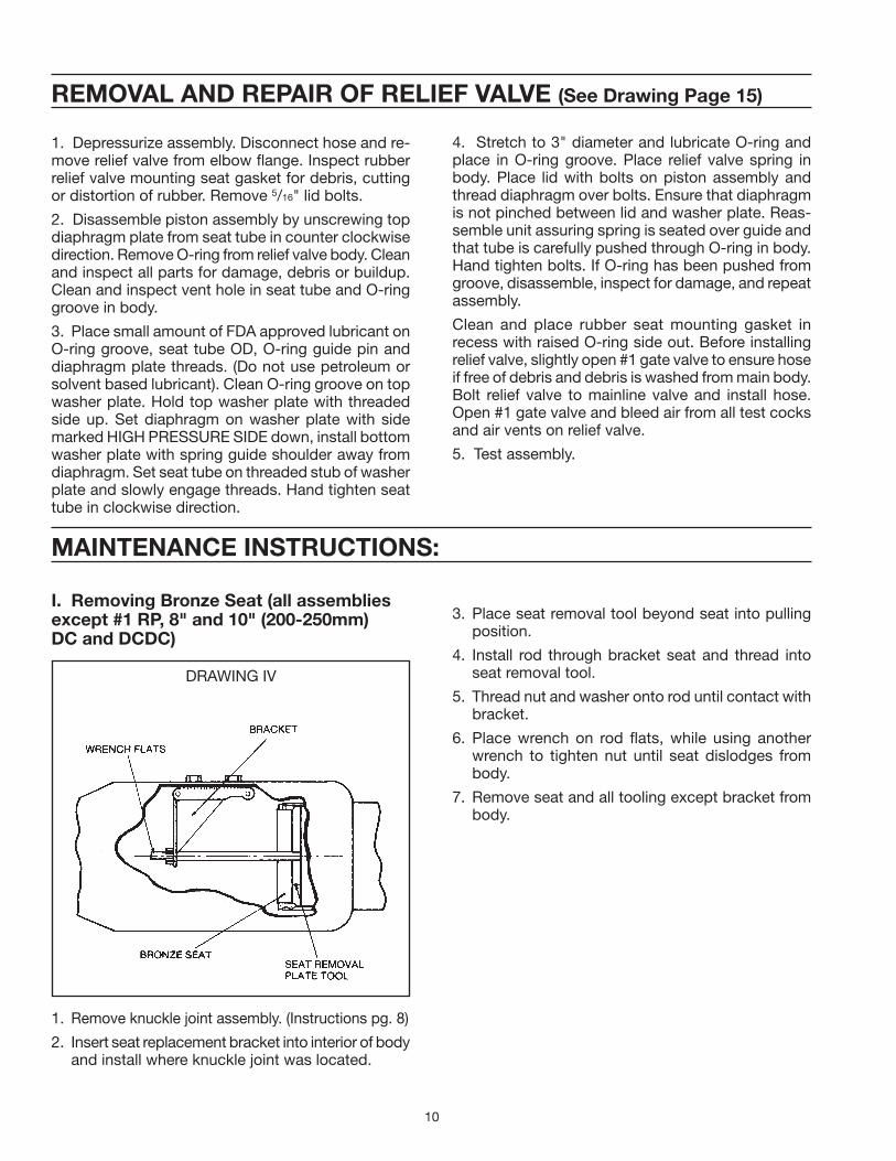
I. Removing Bronze Seat (all assemblies except #1 RP, 8" and 10" (200-250mm)DC and DCDC)
1. Remove knuckle joint assembly. (Instructions pg. 8)
2. Insert seat replacement bracket into interior of body and install where knuckle joint was located.
3. Place seat removal tool beyond seat into pulling position.
4. Install rod through bracket seat and thread into seat removal tool.
5. Thread nut and washer onto rod until contact with bracket.
6. Place wrench on rod fl ats, while using another wrench to tighten nut until seat dislodges from body.
7. Remove seat and all tooling except bracket from body.

11
DRAWING VI
DRAWING V
MAINTENANCE INSTRUCTIONS:
Installing New Bronze Seat (Drawing V)
1. Clean debris from seat area.
2. Lubricate seat area with water soluble FDA ap-proved lubricant.
3. Install tooling as per Drawing V.
4. Using two crescent wrenches, tighten nuts on rod in opposite directions until seat, with O-ring, is securely into place. Visually inspect seat to ensure contact with body.
5. Remove tooling.
6. Install knuckle joint and lid.
II. Removing and Installing bronze seat (1st check 4000RP and 8" and 10"(200-250mm) DC & DCDC)
Drawing VI
Note: Procedure is identical to previous removal and installation of seat.
12
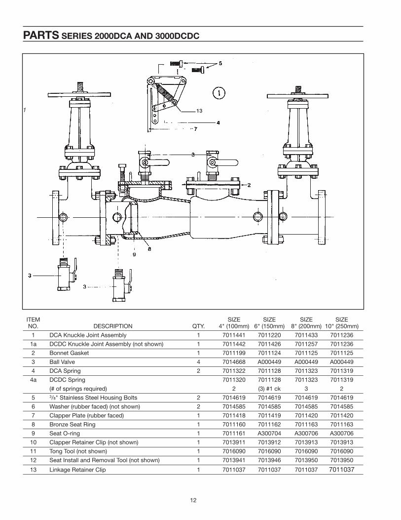
PARTS SERIES 2000DCA AND 3000DCDC
ITEM SIZE SIZE SIZE SIZE NO. DESCRIPTION QTY. 4" (100mm) 6" (150mm) 8" (200mm) 10" (250mm)
1 DCA Knuckle Joint Assembly 1 7011441 7011220 7011433 7011236
1a DCDC Knuckle Joint Assembly (not shown) 1 7011442 7011426 7011257 7011236
2 Bonnet Gasket 1 7011199 7011124 7011125 7011125
3 Ball Valve 4 7014668 A000449 A000449 A000449
4 DCA Spring 2 7011322 7011128 7011323 7011319
4a DCDC Spring 7011320 7011128 7011323 7011319
(# of springs required) 2 (3) #1 ck 3 2
5 3/8" Stainless Steel Housing Bolts 2 7014619 7014619 7014619 7014619
6 Washer (rubber faced) (not shown) 2 7014585 7014585 7014585 7014585
7 Clapper Plate (rubber faced) 1 7011418 7011419 7011420 7011420
8 Bronze Seat Ring 1 7011160 7011162 7011163 7011163
9 Seat O-ring 1 7011161 A300704 A300706 A300706
10 Clapper Retainer Clip (not shown) 1 7013911 7013912 7013913 7013913
11 Tong Tool (not shown) 1 7016090 7016090 7016090 7016090
12 Seat Install and Removal Tool (not shown) 1 7013941 7013946 7013950 7013950
13 Linkage Retainer Clip 1 7011037 7011037 7011037 7011037
1 13
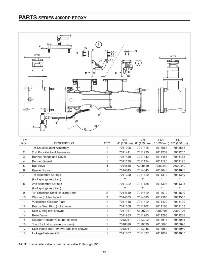
13
ITEM SIZE SIZE SIZE SIZE NO. DESCRIPTION QTY. 4" (100mm) 6" (150mm) 8" (200mm) 10" (250mm)
1 1st Knuckle Joint Assembly 1 7011208 7011415 7015553 7015553
2 2nd Knuckle Joint Assembly 1 7011441 7011220 7011257 7011257
3 Bonnet Flange and Cover 1 7011430 7011442 7011453 7011453
4 Bonnet Gasket 1 7011199 7011124 7011125 7011125
5 Ball Valve 4 7014668 A000449 A000449 A000449
6 Braided Hose 1 7014645 7014645 7014645 7014645
7 1st Assembly Springs 7011320 7011319 7011319 7011319
(# of springs required) 2 2 5 5
8 2nd Assembly Springs 7011322 7011128 7011323 7011323
(# of springs required) 2 2 3 3
9 3/8" Stainless Steel Housing Bolts 2 7014619 7014619 7014619 7014619
10 Washer (rubber faced) 2 7014585 7014585 7014585 7014585
11 Vulcanized Clapper Plate 1 7011418 7011419 7011420 7011420
12 Bronze Seat Ring (not shown) 1 7011160 7011162 7011163 7011163
13 Seat O-ring (not shown) 1 7011161 A300704 A300706 A300706
14 Relief Valve 1 7011283 7011283 7011283 7011283
15 Clapper Retainer Clip (not shown) 1 7013911 7013912 7013913 7013913
16 Tong Tool (all sizes) (not shown) 1 7016090 7016090 7016090 7016090
17 Seat Install and Removal Tool (not shown) 1 7013941 7013946 7013950 7013950
18 Linkage Retainer Clip 1 7011037 7011037 7011037 7011037
PARTS SERIES 4000RP EPOXY
NOTE: Same relief valve is used on all valve 4" through 10"
14
18
18
14
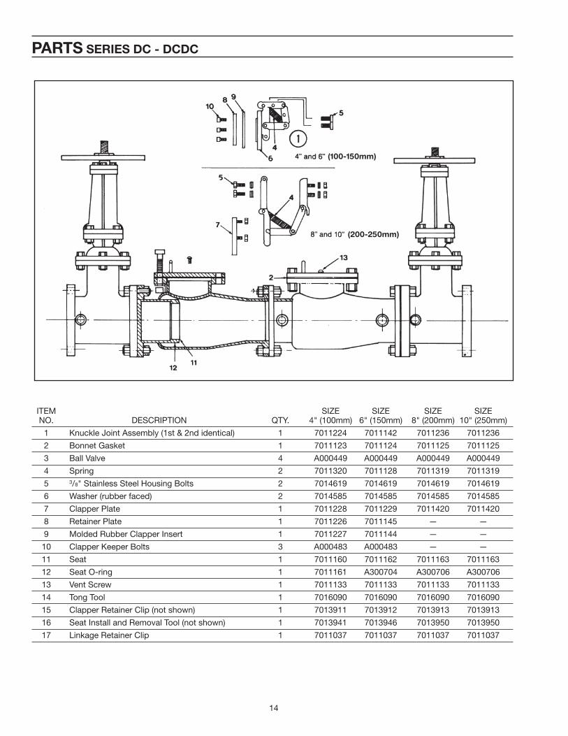
ITEM SIZE SIZE SIZE SIZE NO. DESCRIPTION QTY. 4" (100mm) 6" (150mm) 8" (200mm) 10" (250mm)
1 Knuckle Joint Assembly (1st & 2nd identical) 1 7011224 7011142 7011236 7011236
2 Bonnet Gasket 1 7011123 7011124 7011125 7011125
3 Ball Valve 4 A000449 A000449 A000449 A000449
4 Spring 2 7011320 7011128 7011319 7011319
5 3/8" Stainless Steel Housing Bolts 2 7014619 7014619 7014619 7014619
6 Washer (rubber faced) 2 7014585 7014585 7014585 7014585
7 Clapper Plate 1 7011228 7011229 7011420 7011420
8 Retainer Plate 1 7011226 7011145 — —
9 Molded Rubber Clapper Insert 1 7011227 7011144 — —
10 Clapper Keeper Bolts 3 A000483 A000483 — —
11 Seat 1 7011160 7011162 7011163 7011163
12 Seat O-ring 1 7011161 A300704 A300706 A300706
13 Vent Screw 1 7011133 7011133 7011133 7011133
14 Tong Tool 1 7016090 7016090 7016090 7016090
15 Clapper Retainer Clip (not shown) 1 7013911 7013912 7013913 7013913
16 Seat Install and Removal Tool (not shown) 1 7013941 7013946 7013950 7013950
17 Linkage Retainer Clip 1 7011037 7011037 7011037 7011037
PARTS SERIES DC - DCDC
(100-150mm)
(200-250mm)
15
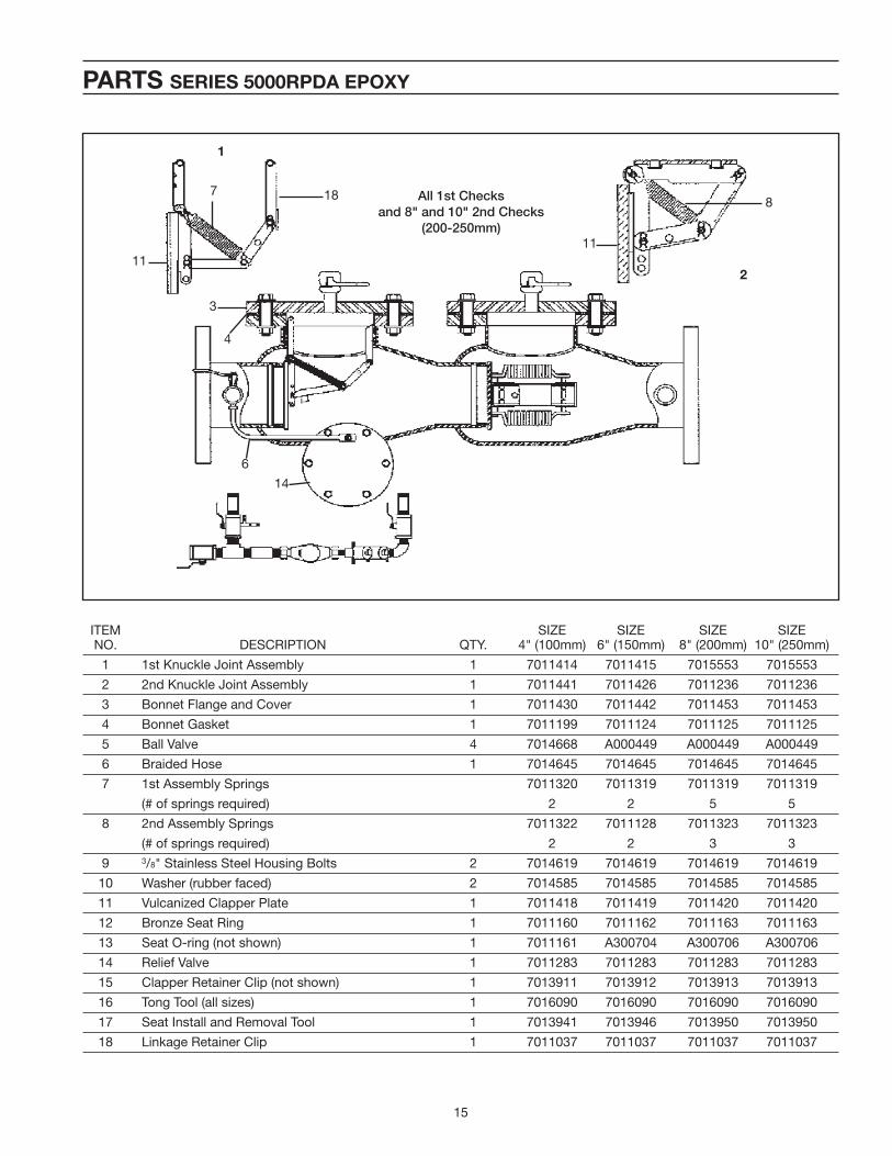
ITEM SIZE SIZE SIZE SIZE NO. DESCRIPTION QTY. 4" (100mm) 6" (150mm) 8" (200mm) 10" (250mm)
1 1st Knuckle Joint Assembly 1 7011414 7011415 7015553 7015553
2 2nd Knuckle Joint Assembly 1 7011441 7011426 7011236 7011236
3 Bonnet Flange and Cover 1 7011430 7011442 7011453 7011453
4 Bonnet Gasket 1 7011199 7011124 7011125 7011125
5 Ball Valve 4 7014668 A000449 A000449 A000449
6 Braided Hose 1 7014645 7014645 7014645 7014645
7 1st Assembly Springs 7011320 7011319 7011319 7011319
(# of springs required) 2 2 5 5
8 2nd Assembly Springs 7011322 7011128 7011323 7011323
(# of springs required) 2 2 3 3
9 3/8" Stainless Steel Housing Bolts 2 7014619 7014619 7014619 7014619
10 Washer (rubber faced) 2 7014585 7014585 7014585 7014585
11 Vulcanized Clapper Plate 1 7011418 7011419 7011420 7011420
12 Bronze Seat Ring 1 7011160 7011162 7011163 7011163
13 Seat O-ring (not shown) 1 7011161 A300704 A300706 A300706
14 Relief Valve 1 7011283 7011283 7011283 7011283
15 Clapper Retainer Clip (not shown) 1 7013911 7013912 7013913 7013913
16 Tong Tool (all sizes) 1 7016090 7016090 7016090 7016090
17 Seat Install and Removal Tool 1 7013941 7013946 7013950 7013950
18 Linkage Retainer Clip 1 7011037 7011037 7011037 7011037
PARTS SERIES 5000RPDA EPOXY
1
2
8
11
14
6
4
3
7 18
11
All 1st Checks
and 8" and 10" 2nd Checks
(200-250mm)

AIR GAP DRAIN INSTALLATION
REAR VIEW SIDE VIEW
AIR GAP DRAIN
APPLICATION
The Air Gap Drain is designed to be installed under the relief valve on Ames RP and RPDA devices to catch minor relief valve discharges created by pressure fl uctuations of the supply line. The Ames Air Gap Drain is approved by the USCFCCCHR.
INSTALLATION INSTRUCTIONS
A. Before installation, check with local authorities as an air gap drain is not approved for all installations.
B. Remove lower two relief valve mounting bolts.
C. Align bolt holes on air gap drain with holes in relief valve fl ange.
D. Insert the two bolts which were removed in Step B through air gap drain and relief valve fl ange, then tighten.
Price List, Product Series or Design are subject to change without notice.
PARTS DIFFERENTIAL PRESSURE RELIEF VALVE FOR SERIES 4000RP
NOTE: Same relief valve is used for all size mainline valves 4" through 10" (100-250mm)
ITEM PART NO. DESCRIPTION QTY. #
1 Complete 1 7011283
2 Mounting Seat Gasket 1 7011295
3 Stainless Steel Seat Tube 1 7011290
4 Mounting Bolt (not shown) 4 7014619
5 Diaphragm 1 7011292
6 Diaphragm Top Plate 1 7011291
7 Diaphragm Bottom Plate 1 7011294
8 Spring 1 A300887
9 O-ring 1 7011233
10 Repair Kit (#2, #5, #9) 1 7013955
NOTE: The Ames Differential Pressure Relief Valve (relief valve) is designed to open and discharge if the fi rst mainline
check is fouled; accordingly if the relief valve is discharging the fi rst service procedure is to examine the fi rst check
for fouling. The Ames relief valve requires minimal service requirements.
RELIEF VALVE (Section View)
IOM-A-BPA 0904 EDP#7016815 ©Ames Fire & Waterworks 2009
www.amesfirewater.com
A Division of Watts Water Technologies, Inc. USA: Backflow- 1427 N. Market Blvd • Suite #9 • Sacramento, CA 95834 • T: 916-928-0123 • F: 916-928-9333
Control Valves- 18550 Hansen Road • Houston, TX 77075 • T: 713-943-0688 • F: 713-944-9445
Canada: 5435 North Service Rd. • Burlington, ONT. L7L 5H7• T: 905-332-4090 • F: 905-332-7068