Embed Size (px)
Citation preview
Chauvin Arnoux® Inc. 15 Faraday Drive • Dover, NH 03820 USA • (603) 749-6434 • Fax (603) 742-2346 • www.aemc.com
Issue 22 “WATTS CURRENT” TECHNICAL BULLETIN Fall 2020 / Winter 2021
Ground Resistance Testers Models 6422/6424
Inside This Issue: Special Report: Grounding and Bonding Testing
New AEMC Products: Ground Resistance Testers Models 6422 / 6424
“WATTS CURRENT” TECHNICAL BULLETIN Issue 22 Fall 2020 / Winter 2021
2
W
SPECIAL REPORT:
Grounding and Bonding Testing
e live in a golden age of grounding systems. Grounding (also called earthing) is more important than ever – not only to protect personnel and equipment from dangerous fault currents, but also to
eliminate induced charges that can “fry” delicate electronics such as computers, broadcast equipment, and controllers. We have at our disposal the most advanced ground testing technology, capable of measuring with unprecedented precision and automatically performing complex mathematical calculations with the press of a button. Grounding systems now come in a variety of design choices, to accommodate a broad spectrum of soil types and locations. And we have a wealth of expert information available to guide us, in the form of books, articles, and videos providing detailed explanations every step of the way.
Despite all this, many of us are sometimes less than satisfied with answers we receive when asking two seemingly straightforward questions: Is my grounding system adequate? And is the equipment in my facility safe from fault currents? At first glance, these questions may appear to be asking essentially the same thing. But as this article explains, there is a critical difference between the two -- and recognizing this difference will help you correctly interpret your test data and decide which measures to take to ensure your electrical systems meet all regulatory safety specifications.
Grounding System Basics As we mentioned, numerous sources explain how grounding works. Unfortunately, the terminology used by these authorities can be inconsistent. Some apply the term “grounding” broadly, in a way that includes connections that more accurately should be called bonding (a concept we will discuss shortly). Others state grounding provides a low-resistance path to earth to clear fault currents, a description that is both misleading and potentially dangerous. So to establish context for the remainder of this article, let’s take a moment to review some very basic electrical concepts.
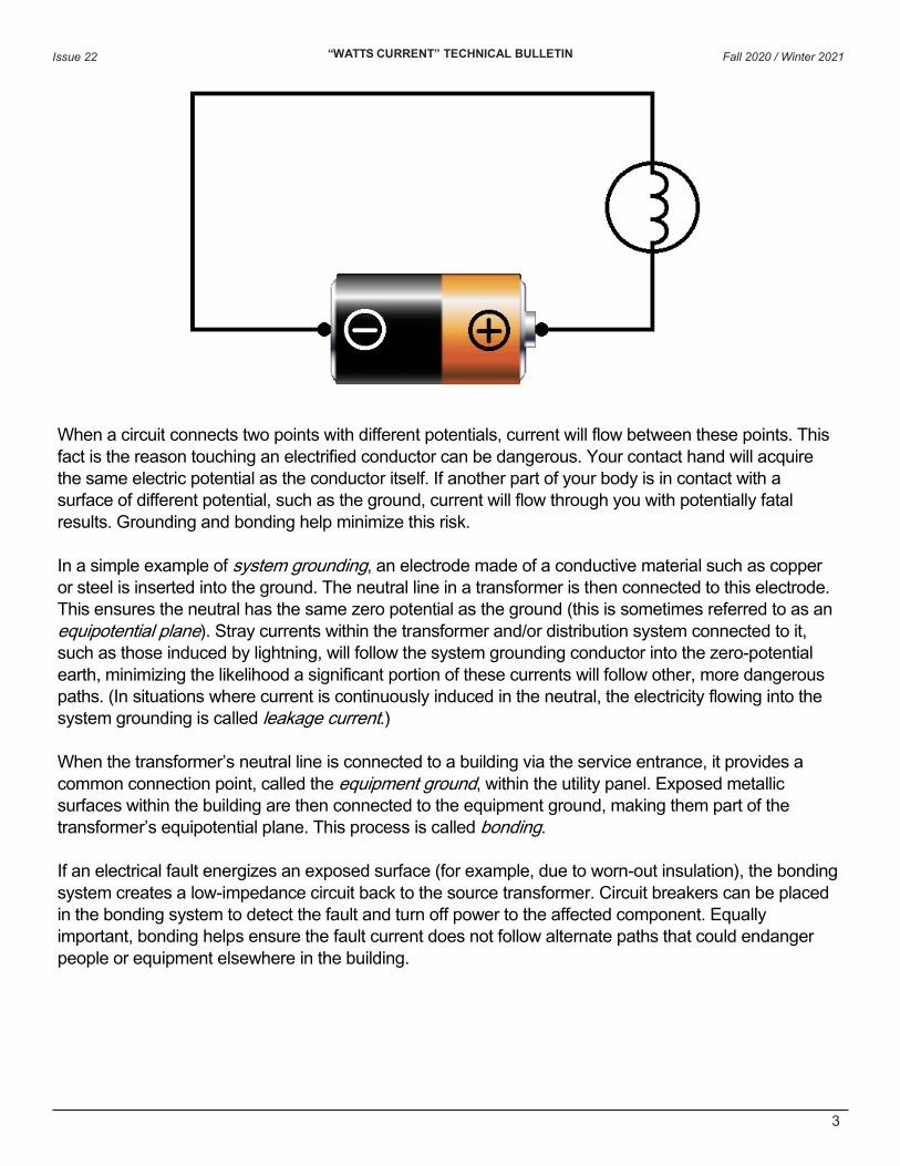
For electricity to flow, a circuit must exist in which a conductive loop returns the electricity back to its source. A simple battery wiring diagram (see below), with current looping between the battery’s terminals, is often used to illustrate this point. This concept applies regardless of the source of the electricity.
In our battery diagram, the reason current flows from one terminal to the other is because the terminals have different electrical potential values. Electric potential is the amount of potential energy that exists between a point in an electrical circuit and a second reference point, usually the ground. This is typically measured in volts, with the ground assigned a value of zero. (In reality, circumstances can occasionally produce non-zero ground potentials. But for simplicity we’ll assume ground = 0.)
“WATTS CURRENT” TECHNICAL BULLETIN Issue 22 Fall 2020 / Winter 2021
3
When a circuit connects two points with different potentials, current will flow between these points. This fact is the reason touching an electrified conductor can be dangerous. Your contact hand will acquire the same electric potential as the conductor itself. If another part of your body is in contact with a surface of different potential, such as the ground, current will flow through you with potentially fatal results. Grounding and bonding help minimize this risk.
In a simple example of system grounding, an electrode made of a conductive material such as copper or steel is inserted into the ground. The neutral line in a transformer is then connected to this electrode. This ensures the neutral has the same zero potential as the ground (this is sometimes referred to as an equipotential plane). Stray currents within the transformer and/or distribution system connected to it, such as those induced by lightning, will follow the system grounding conductor into the zero-potential earth, minimizing the likelihood a significant portion of these currents will follow other, more dangerous paths. (In situations where current is continuously induced in the neutral, the electricity flowing into the system grounding is called leakage current.)
When the transformer’s neutral line is connected to a building via the service entrance, it provides a common connection point, called the equipment ground, within the utility panel. Exposed metallic surfaces within the building are then connected to the equipment ground, making them part of the transformer’s equipotential plane. This process is called bonding.
If an electrical fault energizes an exposed surface (for example, due to worn-out insulation), the bonding system creates a low-impedance circuit back to the source transformer. Circuit breakers can be placed in the bonding system to detect the fault and turn off power to the affected component. Equally important, bonding helps ensure the fault current does not follow alternate paths that could endanger people or equipment elsewhere in the building.
“WATTS CURRENT” TECHNICAL BULLETIN Issue 22 Fall 2020 / Winter 2021
4
In addition, grounding prevents induced electricity sparking. Electrical circuits can induce electricity in nearby metallic objects. Coming in contact with these objects can create a spark. This discharge can cause significant damage to circuit boards and other sophisticated components. To help avoid this, facilities typically include one or more electrodes placed outside the building and connected to the equipment ground. This allows induced current to continually flow safely into the earth, rather than build up to potentially damaging levels.
To conclude, an effective grounding system must meet two basic criteria:
• The grounding electrode (or equivalent) must have low resistance to earth.
• The bonding system connecting the metallic surfaces to the source neutral and grounding systemmust be capable of carrying the highest likely fault currents with minimal impedance.
If either of these conditions is not met, the metallic surfaces will have non-zero potential. Therefore, rather than going back to the source via the grounding system, fault currents may follow other, more dangerous paths; and induced electricity may build to problematic levels. In short, the grounding system will fail to perform the function for which it is designed.
This is why determining the efficiency of your grounding is at its core a two-step process. Of course it’s essential to test the electrode to ensure its ground resistance falls below regulatory specifications. At the same time, the bonding must also be tested to ensure it provides a low-resistance circuit back to the source.
Ground System Testing Designing and installing a new grounding system generally involves the following:
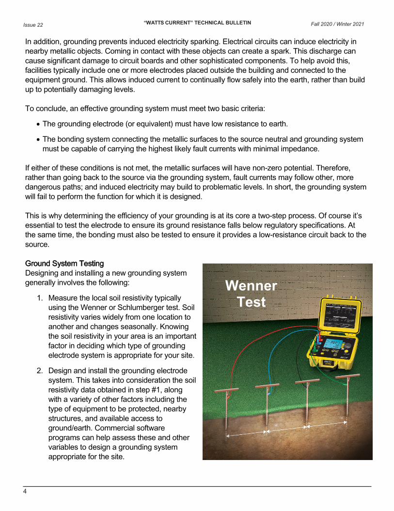
1. Measure the local soil resistivity typicallyusing the Wenner or Schlumberger test. Soilresistivity varies widely from one location toanother and changes seasonally. Knowingthe soil resistivity in your area is an importantfactor in deciding which type of groundingelectrode system is appropriate for your site.
2. Design and install the grounding electrodesystem. This takes into consideration the soilresistivity data obtained in step #1, alongwith a variety of other factors including thetype of equipment to be protected, nearbystructures, and available access toground/earth. Commercial softwareprograms can help assess these and othervariables to design a grounding systemappropriate for the site.
Wenner Test
“WATTS CURRENT” TECHNICAL BULLETIN Issue 22
5
3. Measure the resistance of the installed electrode, usually via the Fall-of-Potential test. This mustbe done before the electrode is connected to your facility and after the earth surrounding theelectrodes has had sufficient time to settle. The National Electrical Code specifies the totalimpedance of the grounding system of a typical building should be 25 ohms or less, with 5 ohmsor less suggested for power transmission lines and facilities with sensitive electronic equipment.If measuring the electrode does not meet these readings, several measures can be taken tolower the impedance.
4. Test the bonding and continuity of the connections between the grounding electrode, theequipment ground, and all exposed metal surfaces in your facility.
Tests such as the Wenner and Fall-of-Potential are time-tested, and many resources are available explaining how to perform them.
Once the grounding system is installed, it should be monitored regularly to ensure it still performs to its original design specifications. All grounding systems deteriorate over time – their effective function depends on an ion exchange process that slowly destroys the metal from which the electrodes are made. This can compromise the grounding system to the point of ineffectiveness within several years. In addition, corrosion, vibration, and other causes can render bonds ineffective. Testing should also be performed whenever the grounding system has been expanded or modified, for instance by adding or upgrading equipment in the facility.
Testing an installed system presents a number of complications, especially if the system cannot be de-energized, disconnected, and isolated from the rest of the facility. For example, the Fall-of-Potential test cannot be accurately performed on a connected electrode, for reasons we explain below. And even if the electrode can be disconnected, several factors can profoundly affect your measurements.
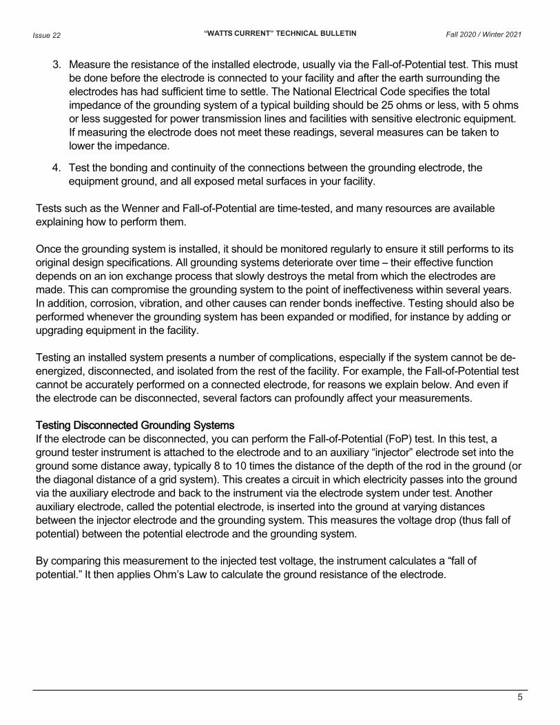
Testing Disconnected Grounding Systems If the electrode can be disconnected, you can perform the Fall-of-Potential (FoP) test. In this test, a ground tester instrument is attached to the electrode and to an auxiliary “injector” electrode set into the ground some distance away, typically 8 to 10 times the distance of the depth of the rod in the ground (or the diagonal distance of a grid system). This creates a circuit in which electricity passes into the ground via the auxiliary electrode and back to the instrument via the electrode system under test. Another auxiliary electrode, called the potential electrode, is inserted into the ground at varying distances between the injector electrode and the grounding system. This measures the voltage drop (thus fall of potential) between the potential electrode and the grounding system.
By comparing this measurement to the injected test voltage, the instrument calculates a “fall of potential.” It then applies Ohm’s Law to calculate the ground resistance of the electrode.
Fall 2020 / Winter 2021
“WATTS CURRENT” TECHNICAL BULLETIN Issue 22
6
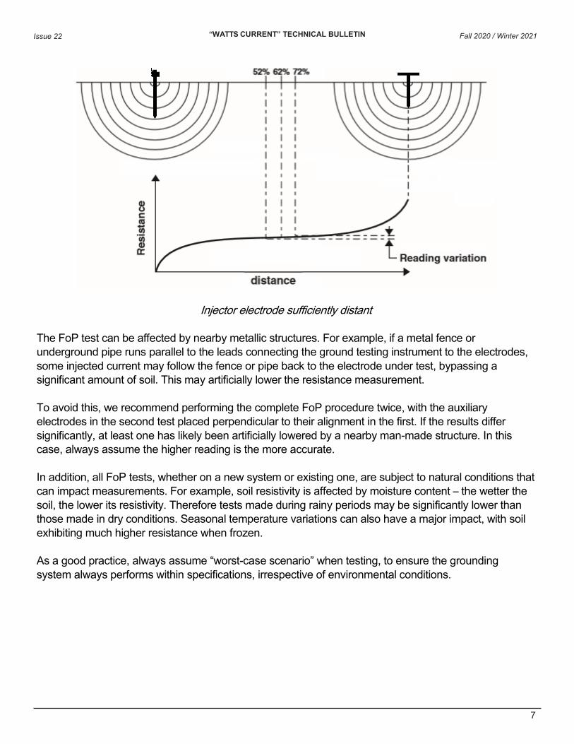
To ensure the injector electrode is sufficiently distant from the electrode under test to avoid its “sphere of influence,” a simplified method is to perform the FoP test with the potential electrode 62% the distance between the ground and injector electrodes. Then repeat the test by moving the potential electrode to 52% the distance. Finally, perform the test a third time at 72% this distance.
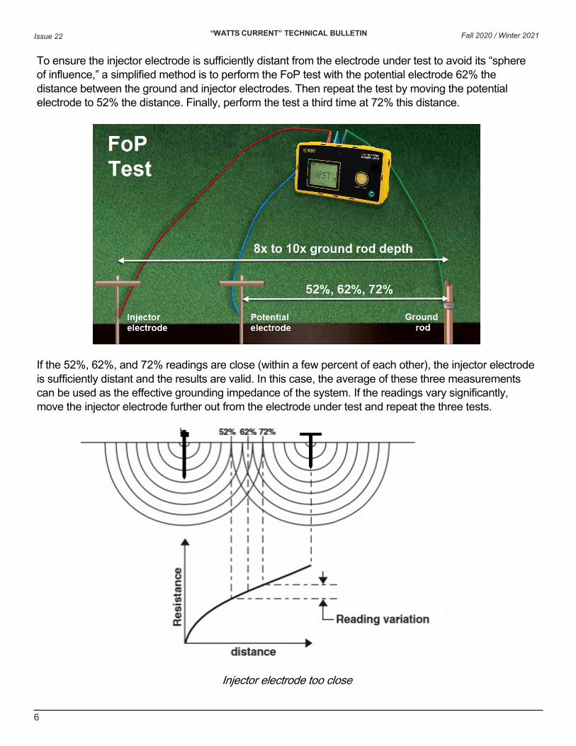
If the 52%, 62%, and 72% readings are close (within a few percent of each other), the injector electrode is sufficiently distant and the results are valid. In this case, the average of these three measurements can be used as the effective grounding impedance of the system. If the readings vary significantly, move the injector electrode further out from the electrode under test and repeat the three tests.
Injector electrode too close
Fall 2020 / Winter 2021
“WATTS CURRENT” TECHNICAL BULLETIN Issue 22
7
Injector electrode sufficiently distant
The FoP test can be affected by nearby metallic structures. For example, if a metal fence or underground pipe runs parallel to the leads connecting the ground testing instrument to the electrodes, some injected current may follow the fence or pipe back to the electrode under test, bypassing a significant amount of soil. This may artificially lower the resistance measurement.
To avoid this, we recommend performing the complete FoP procedure twice, with the auxiliary electrodes in the second test placed perpendicular to their alignment in the first. If the results differ significantly, at least one has likely been artificially lowered by a nearby man-made structure. In this case, always assume the higher reading is the more accurate.
In addition, all FoP tests, whether on a new system or existing one, are subject to natural conditions that can impact measurements. For example, soil resistivity is affected by moisture content – the wetter the soil, the lower its resistivity. Therefore tests made during rainy periods may be significantly lower than those made in dry conditions. Seasonal temperature variations can also have a major impact, with soil exhibiting much higher resistance when frozen.
As a good practice, always assume “worst-case scenario” when testing, to ensure the grounding system always performs within specifications, irrespective of environmental conditions.
Fall 2020 / Winter 2021
“WATTS CURRENT” TECHNICAL BULLETIN Issue 22
8
Testing Connected Grounding Systems In many facilities, it is impossible or infeasible to disconnect the grounding system. In these cases, the Fall-of-Potential test produces unreliable results. For instance, if the test is performed on a connected electrode located near a transfer station, a portion of the injected current may pass to the station’s extensive grounding system. The current then flows through the electrical utility’s common ground line back to the electrode under test. This creates an alternate circuit which will show a false low impedance measurement that invalidates any results you may obtain. Other nearby grounding electrodes may similarly create loops outside the intended test circuit.
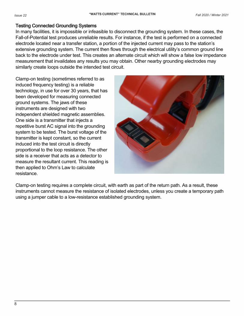
Clamp-on testing (sometimes referred to as induced frequency testing) is a reliable technology, in use for over 30 years, that has been developed for measuring connected ground systems. The jaws of these instruments are designed with two independent shielded magnetic assemblies. One side is a transmitter that injects a repetitive burst AC signal into the grounding system to be tested. The burst voltage of the transmitter is kept constant, so the current induced into the test circuit is directly proportional to the loop resistance. The other side is a receiver that acts as a detector to measure the resultant current. This reading is then applied to Ohm’s Law to calculate resistance.
Clamp-on testing requires a complete circuit, with earth as part of the return path. As a result, these instruments cannot measure the resistance of isolated electrodes, unless you create a temporary path using a jumper cable to a low-resistance established grounding system.
Fall 2020 / Winter 2021
“WATTS CURRENT” TECHNICAL BULLETIN Issue 22
9
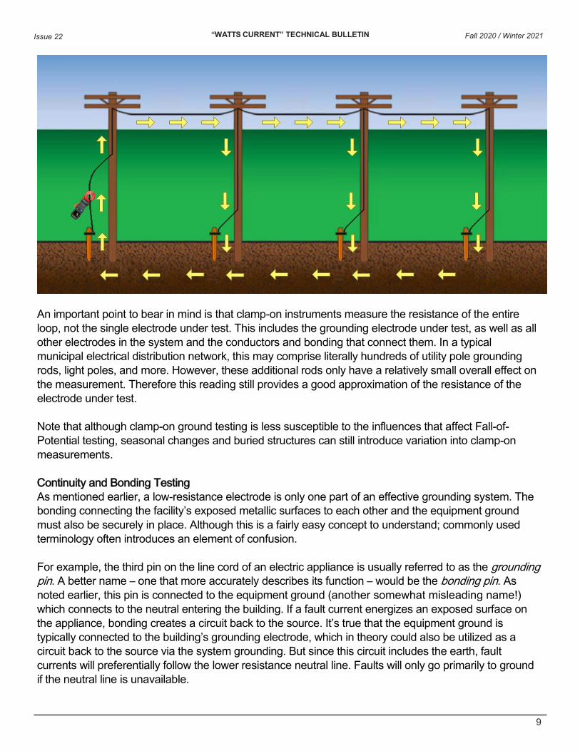
An important point to bear in mind is that clamp-on instruments measure the resistance of the entire loop, not the single electrode under test. This includes the grounding electrode under test, as well as all other electrodes in the system and the conductors and bonding that connect them. In a typical municipal electrical distribution network, this may comprise literally hundreds of utility pole grounding rods, light poles, and more. However, these additional rods only have a relatively small overall effect on the measurement. Therefore this reading still provides a good approximation of the resistance of the electrode under test.
Note that although clamp-on ground testing is less susceptible to the influences that affect Fall-of-Potential testing, seasonal changes and buried structures can still introduce variation into clamp-on measurements.
Continuity and Bonding Testing As mentioned earlier, a low-resistance electrode is only one part of an effective grounding system. The bonding connecting the facility’s exposed metallic surfaces to each other and the equipment ground must also be securely in place. Although this is a fairly easy concept to understand; commonly used terminology often introduces an element of confusion.
For example, the third pin on the line cord of an electric appliance is usually referred to as the grounding pin. A better name – one that more accurately describes its function – would be the bonding pin. As noted earlier, this pin is connected to the equipment ground (another somewhat misleading name!) which connects to the neutral entering the building. If a fault current energizes an exposed surface on the appliance, bonding creates a circuit back to the source. It’s true that the equipment ground is typically connected to the building’s grounding electrode, which in theory could also be utilized as a circuit back to the source via the system grounding. But since this circuit includes the earth, fault currents will preferentially follow the lower resistance neutral line. Faults will only go primarily to ground if the neutral line is unavailable.
Fall 2020 / Winter 2021
“WATTS CURRENT” TECHNICAL BULLETIN Issue 22
10
This is a critical point that needs to be stressed: The primary purpose of the grounding pin is not to provide fault currents with a path to ground. Instead, this pin bonds exposed electrical surfaces to the neutral line, creating a circuit for fault currents to return to the source. Similarly, the purpose of the equipment ground is not solely to provide a connection to the building’s own grounding electrode. It also serves as a common point to which your building’s bonding system connects to the source neutral.
Yet a great deal of misunderstanding about this persists, often fueled by the confusing terminology involved. This in turn has sometimes resulted in less-than-optimal fault current protection designs. A facility that relies entirely on its grounding electrodes to dissipate fault currents, without taking bonding into consideration, may be subjecting its personnel to needless risk.
Two tests, the ground continuity and ground bonding, are commonly performed to confirm the efficacy of equipment bonding connections:
• Continuity testing is typically a quick “pass/fail” type procedure that confirms whether or not aconnection exists between the exposed metallic surface and the conductor that connects it to theequipment ground. A low test current is used, generally in the 10’s of milliamps. Results areusually indicated by a green or red LED on the instrument, often without additional measurementreadings. Many different types of electrical test instruments include a continuity feature, so theequipment requirements for performing this test are often modest – in many cases a handheldvoltmeter will suffice. However, note that this test will not indicate the quality of a bond.
• Bonding (or bond) testing is a more stringent test that measures the integrity of the equipmentground connection. This involves passing a high current through the connection (10A or higherdepending on the specification) and measuring the resistance of the bonding circuit, typically inthe milliohm or micro-ohm range. In addition to ensuring a low-resistance connection exists, thebond test also confirms that the conductors can handle high fault currents without burning out.Bonding testing requires instruments that can produce high test currents, so equipmentrequirements are usually more substantial than for continuity tests; and may involve productsspecifically designed for this purpose. And since even small amounts of resistance may affectthe reading and raise it beyond accepted standards, test probes used for bonding testing shouldeither be Kelvin-type, or the instrument must have the ability to eliminate the test lead resistancefrom the measurement.
(Some sources combine these two tests under the name “ground continuity,” and differentiate them as the “low current method” and “high current method.” In this article, we will refer to these as two separate tests.)
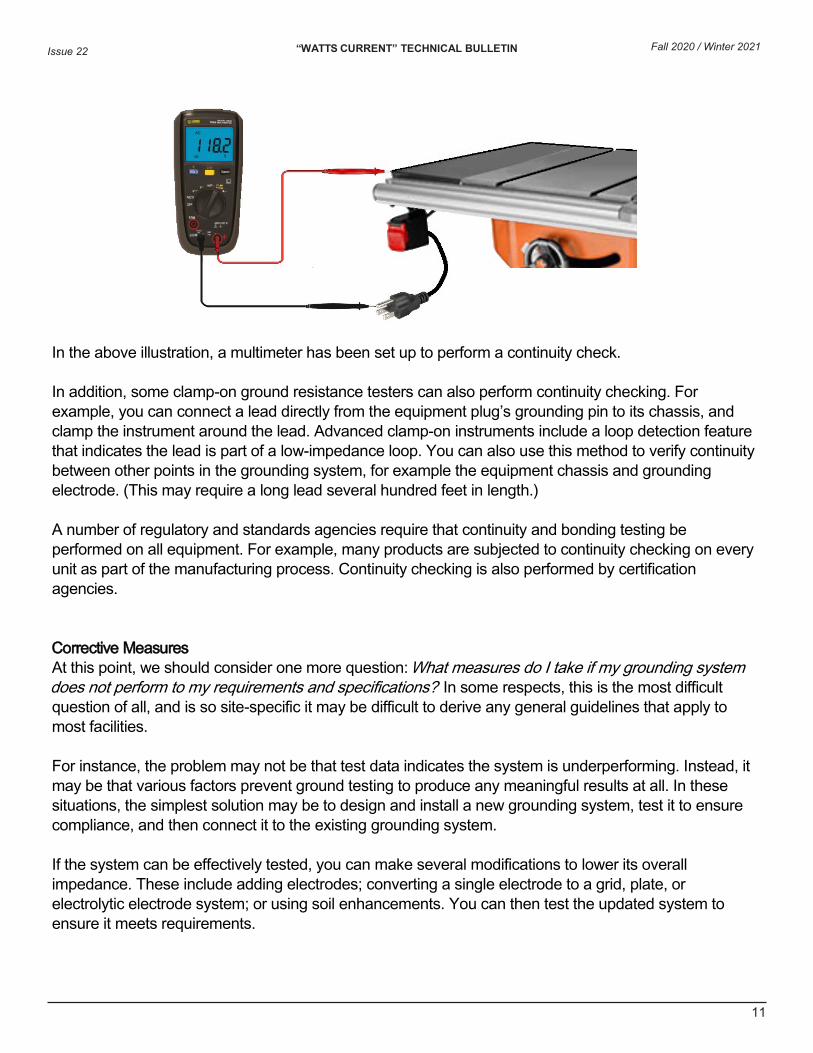
The steps for performing both tests are similar: 1. Disconnect the equipment from its power source.2. Connect one of the test instrument’s leads to the grounding line in the equipment’s power cable.
In a typical example, the lead is connected to the grounding pin in the instrument’s power plug.3. Connect the second instrument lead to the exposed metallic surface of the equipment under test,
such as the chassis.4. Perform the test as instructed by the instrument’s documentation.
Fall 2020 / Winter 2021
“WATTS CURRENT” TECHNICAL BULLETIN Issue 22
11
In the above illustration, a multimeter has been set up to perform a continuity check.
In addition, some clamp-on ground resistance testers can also perform continuity checking. For example, you can connect a lead directly from the equipment plug’s grounding pin to its chassis, and clamp the instrument around the lead. Advanced clamp-on instruments include a loop detection feature that indicates the lead is part of a low-impedance loop. You can also use this method to verify continuity between other points in the grounding system, for example the equipment chassis and grounding electrode. (This may require a long lead several hundred feet in length.)
A number of regulatory and standards agencies require that continuity and bonding testing be performed on all equipment. For example, many products are subjected to continuity checking on every unit as part of the manufacturing process. Continuity checking is also performed by certification agencies.
Corrective Measures At this point, we should consider one more question: What measures do I take if my grounding system does not perform to my requirements and specifications? In some respects, this is the most difficult question of all, and is so site-specific it may be difficult to derive any general guidelines that apply to most facilities.
For instance, the problem may not be that test data indicates the system is underperforming. Instead, it may be that various factors prevent ground testing to produce any meaningful results at all. In these situations, the simplest solution may be to design and install a new grounding system, test it to ensure compliance, and then connect it to the existing grounding system.
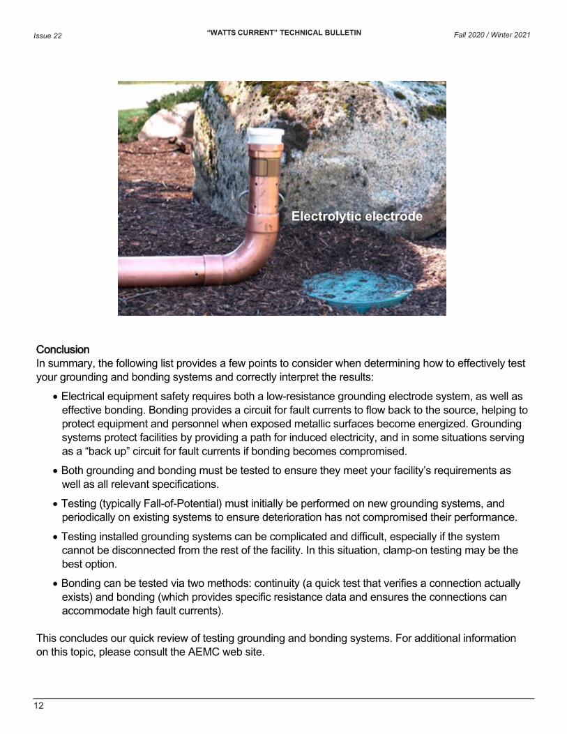
If the system can be effectively tested, you can make several modifications to lower its overall impedance. These include adding electrodes; converting a single electrode to a grid, plate, or electrolytic electrode system; or using soil enhancements. You can then test the updated system to ensure it meets requirements.
Fall 2020 / Winter 2021
“WATTS CURRENT” TECHNICAL BULLETIN Issue 22
12
Conclusion In summary, the following list provides a few points to consider when determining how to effectively test your grounding and bonding systems and correctly interpret the results:
• Electrical equipment safety requires both a low-resistance grounding electrode system, as well aseffective bonding. Bonding provides a circuit for fault currents to flow back to the source, helping toprotect equipment and personnel when exposed metallic surfaces become energized. Groundingsystems protect facilities by providing a path for induced electricity, and in some situations servingas a “back up” circuit for fault currents if bonding becomes compromised.
• Both grounding and bonding must be tested to ensure they meet your facility’s requirements aswell as all relevant specifications.
• Testing (typically Fall-of-Potential) must initially be performed on new grounding systems, andperiodically on existing systems to ensure deterioration has not compromised their performance.
• Testing installed grounding systems can be complicated and difficult, especially if the systemcannot be disconnected from the rest of the facility. In this situation, clamp-on testing may be thebest option.
• Bonding can be tested via two methods: continuity (a quick test that verifies a connection actuallyexists) and bonding (which provides specific resistance data and ensures the connections canaccommodate high fault currents).
This concludes our quick review of testing grounding and bonding systems. For additional information on this topic, please consult the AEMC web site.
Electrolytic electrode
Fall 2020 / Winter 2021
“WATTS CURRENT” TECHNICAL BULLETIN Issue 22
13
T
New Products
Ground Resistance Testers Models 6422/6424
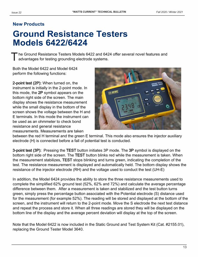
he Ground Resistance Testers Models 6422 and 6424 offer several novel features and advantages for testing grounding electrode systems.
Both the Model 6422 and Model 6424 perform the following functions:
2-point test (2P): When turned on, theinstrument is initially in the 2-point mode. Inthis mode, the 2P symbol appears on thebottom right side of the screen. The maindisplay shows the resistance measurementwhile the small display in the bottom of thescreen shows the voltage between the H andE terminals. In this mode the instrument canbe used as an ohmmeter to check bondresistance and general resistancemeasurements. Measurements are takenbetween the red H terminal and the green E terminal. This mode also ensures the injector auxiliaryelectrode (H) is connected before a fall of potential test is conducted.
3-point test (3P): Pressing the TEST button initiates 3P mode. The 3P symbol is displayed on thebottom right side of the screen. The TEST button blinks red while the measurement is taken. Whenthe measurement stabilizes, TEST stops blinking and turns green, indicating the completion of thetest. The resistance measurement is displayed and automatically held. The bottom display shows theresistance of the injector electrode (RH) and the voltage used to conduct the test (UH-E)
In addition, the Model 6424 provides the ability to store the three resistance measurements used to complete the simplified 62% ground test (52%, 62% and 72%) and calculate the average percentage difference between them. After a measurement is taken and stabilized and the test button turns green, simply press the percentage button associated with the Potential electrode (S) distance used for the measurement (for example 52%). The reading will be stored and displayed at the bottom of the screen, and the instrument will return to the 2-point mode. Move the S electrode the next test distance and repeat the process and store it. When all three readings are stored they will be displayed on the bottom line of the display and the average percent deviation will display at the top of the screen.
Note that the Model 6422 is now included in the Static Ground and Test System Kit (Cat. #2155.01), replacing the Ground Tester Model 3640.
Fall 2020 / Winter 2021
Chauvin Arnoux®, Inc. d.b.a. AEMC® Instruments 15 Faraday Drive • Dover, NH 03820 USA
Tel: (800) 343-1391 • (603) 749-6434 • Fax: (603) 742-2346 www.aemc.com • [email protected]
AEMC®, PowerPad®, and DataView® are registered trademarks of AEMC® Instruments.