Embed Size (px)
Citation preview

TECHNICAL INFORMATION
General Information Ⅰ Technical Information General Information ⅡWorkpiece material grades
Steel, Non-ferrous metal symbol list
SI unit conversion table
Hardness calculating table
Properties of Korloy grades
Technical Info. for Stainless steel
Technical Information for Turning
Technical Information for Milling
Technical Information for Tapers
Technical Information for Endmills
Technical Information for Drilling
The comparision of chip breakers
KORLOY Grade table
The comparision of grades
L02
L06
L07
L08
L09
L10
L12
L20
L24
L27
L30
L36
L37
L40
C O N T E N T S
LTECHNICAL INFORMATION

Gen
eral
In
form
atio
n
2
L
L General Information Ⅰ
Carbon steel and alloy steel for structural use
XC10
-
C22C22EC22RC25C25EC25RC30C30EC30R
C35C35EC35RC40C40EC40R
-
C45C45EC45R-C50C50EC50R
-
C55C55EC55R
C60C60EC60R
-
-
-
-
30Г
35Г
40Г
40Г
45Г
45Г50Г
50Г
-
60Г
SM10C
SM15C
SM20C
SM25C
SM30C
SM35C
SM40C
SM43C
SM45C
SM48CSM50C
SM53C
SM55C
SM58C
C10
C15E4C15M2-
C25C25E4C25M2C30C30E4C30M2
C35C35E4C35M2C40C40E4C40M2
-
C45C45E4C45M2-C50C50E4C50M2
-
C55C55E4C55M2
C60C60E4C60M2
S10C
S15C
S20C
S25C
S30C
S35C
S40C
S43C
S45C
S48CS50C
S53C
S55C
S58C
040A10045A10045M10055M15
070M20C22, C22EC22RC25C25EC25R080A30080M30CC30C30EC30RC35C35EC35R080M40C40C40EC40R080A42
C45C45EC45R080A47080M50C50C50EC50R-
070M55C55C55EC55RC60C60EC60R
C10EC10R
C15EC15RC22C22EC22RC25C25EC25RC30C30EC30R
C35C35EC35RC40C40EC40R
-
C45C45EC45R-C50C50EC50R
-
C55C55EC55R
C60C60EC60R
1010 1015 1020 1025 1030 1035 1039 1040 1042 1043 1045 1046 - 1049 1050 1053 1055 1059 1060
KoreaType
Car
bon
stee
l
KS
ISO
ISO
Japan
JIS
U.S.A Great BritainAISISAE
BSBS/EN
GermanyDIN
DIN/EN
FranceNF
NF/EN
Russia
GOCT
Nickelchromiumsteel
Nickelchromiummolybdenumsteel
Chromiumsteel
SNC236SNC415(H)SNC631(H)SNC815(H)SNC836SNCM220
SNCM240
SNCM415SNCM420(H)SNCM431SNCM439SNCM447SNCM616SNCM625SNCM630SNCM815SCr415(H)
SCr420(H)
SCr430(H)
SCr435(H)
SCr440(H)
SCr445(H)
---15NiCr13-20NiCrMo220NiCrMoS2
41CrNiMo241CrNiMoS2----------
20Cr4(H)20CrS434Cr434CrS434Cr434CrS437Cr437CrS437Cr437CrS441Cr441CrS4
SNC236SNC415(H)SNC631(H)SNC815(H)SNC836SNCM220
SNCM240
SNCM415SNCM420(H)SNCM431SNCM439SNCM447SNCM616SNCM625SNCM630SNCM815SCr415(H)
SCr420(H)
SCr430(H)
SCr435(H)
SCr440(H)
SCr445(H)
---655M13(655H13)-805A20805M20805A22805M22-
----------
-
34Cr434CrS437Cr437CrS4
530M4041Cr441CrS4
---15NiCr13-20NiCrMo220NiCrMoS2
-
---------17Cr317CrS3-
34Cr434CrS437Cr437CrS4
41Cr441CrS4
-----20NCD2
-
----------
-
34Cr434CrS437Cr437CrS4
41Cr441CrS4
40XH-30XH3A---
-
-20XH2M(20XHM)-------15X15XA20X
30X
35X
40X
45X
Allo
y st
eel
- - - - - 86158617(H)8620(H)8622(H)86378640-4320(H)- 4340- - - - - - 5120(H)
5130(H)5132(H)5135(H)
5140(H)
• The above Alloy steel can supplied by domestic manufacturing

Gen
eral In
form
ation
3
L
LGeneral Information Ⅰ
KoreaType
KS
ISO
ISO
Japan
JIS
U.S.A Great BritainBS
BS/EN
GermanyDIN
DIN/EN
FranceNF
NF/EN
Russia
GOCT
SCM415(H)SCM418(H)
SCM420(H)SCM430
SCM432SCM435(H)
SCM440(H)
SCM445(H)
SMn420(H)SMn433(H)
SMn438(H)
SMn443(H)
SMnC420(H)SMnC443(H)SACM645
-18CrMo418CrMoS4--
-34CrMo434CrMoS442CrMo442CrMoS4
-
22Mn6(H)-
36Mn6(H)
42Mn6(H)
--41CrAlMo74
SCM415(H)SCM418(H)
SCM420(H)SCM430
SCM432SCM435(H)
SCM440(H)
SCM445(H)
SMn420(H)SMn433(H)
SMn438(H)
SMn443(H) SMnC420(H)SMnC443(H)SACM645
--
708M20(708H20)-
-34CrMo434CrMoS4708M70709M4042CrMo442CrMoS4-
150M19150M36
150M36
-
---
-18CrMo418CrMoS4--
-34CrMo434CrMoS442CrMo442CrMoS4
-
--
-
---
--
--
-34CrMo434CrMoS442CrMo442CrMoS4
-
--
-
---
-20XM
20XM30XM30XMA-35XM
-
-
-30Г235Г235Г240Г240Г245Г2---
- - - 4130
- (4135H)4137(H)4140(H)4142(H)
4145(H)4147(H)1522(H)1534
1541(H)
1541(H)
- - -
Chromiummolybdenumsteel
Manganesesteel andManganesechromiumsteel
Aluminum chromiummolybdenumsteel
AISISAE
France"NFNF/EN"
Z 85 WDCV
6-5-2-5
105WC13
Z200C12
Z100CDV5
Z30WCV9
Z40CDV5
55NCDV7
SKH2SKH3SKH4SKH10SKH51SKH52SKH53SKH54SKH55SKH56SKH57SKH58SKH59STS11STS2STS21STS5STS51STS7STS8STS4STS41STS43STS44STS3STS31STS93STS94STS95STD1STD11STD12STD4STD5STD6STD61STD62STD7STD8STF3STF4
HS18-0-1---HS6-5-2HS6-6-2HS6-5-3HS6-5-4HS6-5-2-5-HS10-4-3-10HS2-9-2HS2-9-1-8---------105V--105WCr1---210Cr12-100CrMoV5-X30WCrV9-3X37CrMoV5-1X40CrMoV5-1X35CrWMoV532CrMoV12-28--55NiCrMoV7
SKH2SKH3SKH4SKH10SKH51SKH52SKH53SKH54SKH55SKH56SKH57SKH58SKH59SKS11SKS2SKS21SKS5SKS51SKS7SKS8SKS4SKS41SKS43SKS44SKS3SKS31SKS93SKS94SKS95SKD1SKD11SKD12SKD4SKD5SKD6SKD61SKD62 SKD7SKD8SKT3SKT4
BM 2
BM 35
BD3
BA2
BH21
BH13
Germany
S6/5/2
S6/5/2/5
S2/9/2
105WCr6
X210Cr12
X100CrMoV5 1
X30WCrV9 3
X40CrMoV5 1
55NiCrMoV6
T1T4T5T15M2M3-1M3-2M4M 35M36- M7M42F2- - - L6- - - - W2-9 1/W2-8 1-2- - - - - D3D2A2- H21H11H13H12H10H19- L6
Hig
h sp
eed
stee
lA
lloy
tool
ste
el
KoreaType
KS
ISO
ISO
Japan
JIS
U.S.A Great BritainBS
BS/EN
GermanyDIN
DIN/EN
FranceNF
NF/EN
Russia
GOCTAISISAE
• The above Alloy steel can supplied by domestic manufacturing
• The above High speed steel can supplied by domestic manufacturing
Tool steel
Allo
y st
eel

Gen
eral
In
form
atio
n
4
L
General Information ⅠL
S250S250PbS 300
S300Pb
100Cr6
SUM11SUM12SUM21SUM22SUM22LSUM23SUM23LSUM24LSUM25SUM31SUM31LSUM32SUM41SUM42SUM43STB1STB2STB3
STB4STB5
--9S2011SMn2811SMnPb28--11SMnPb2812SMn35-----44SMn28-B1B2
--
SUM11SUM12SUM21SUM22SUM22LSUM23SUM23LSUM24LSUM25SUM31SUM31LSUM32SUM41SUM42SUM43SUJ1SUJ2SUJ3 SUJ4SUJ5
230M07
240M07
534A99
9SMn289SMnPb289SMn36
9SMnPb36
100Cr6
111011091212121312L131215-12L14-1117--113711411144-52100ASTM A485Grade 1--
Free
cut
ting
carb
on s
teel
H
igh
carb
onch
rom
ium
KoreaType
KS
ISO
ISO
Japan
JIS
U.S.A Great BritainBS
BS/EN
GermanyDIN
DIN/EN
FranceNF
NF/EN
Russia
GOCTAISISAE
• The above Special speed steel can supplied by domestic manufacturing
Z12CMN17-07Az
Z11CN17-08
Z12CN18-09
Z8CNF18-09
Z7CN18-09
Z3CN19-11Z6CN19-09AzZ3CN18-10Az
Z8CN18-12Z10CN24-13Z8CN25-20Z7CND17-12-02Z6CND18-12-03Z3CND17-12-02Z3CND17-12-03
Z6CNT18-10Z6CNNb18-10Z6CN18-16Z8CA12Z3C14
Z8C17Z8CF17Z8CD17-01Z3CDT18-02Z1CD26-01
Z13C13Z11CF13Z20C13Z15CN16-02Z70C15Z6CNU17-04Z9CNA17-07
12X17•9AH407X16H6
12X18H9
12X18H10E
08X18H10
03X18H11
06X18H11
10X23H18
03X17H14M3
08X18H10T08X18H12
12X17
20X1320X17H2
09X17H7IO
STS201STS202STS301STS301LSTS301J1STS302STS302BSTS303STS303SeSTS303CuSTS304
STS304LSTS304N1STS304LNSTS304J1STS305STS309SSTS310SSTS316
STS316L
STS316NSTS317STS321STS347STS384STS405STS410LSTS429STS430STS430FSTS434STS444STSXM27STS403STS410STS416STS420J1STS431STS440ASTS630STS631STS631J1
X12CrMnNiN17-7-5X12CrMnNiN18-9-5X10CrNi18-8X2CrNiN18-7
X12CrNiSi18-9-3X10CrNiS18-9
X5CrNi18-9X2CrNi18-9X2CrNi19-11X5CrNiN18-8X2CrNiN18-8
X6CrNi18-12
X6CrNi25-20X5CrNiMo17-12-2X3CrNiMo17-12-3X2CrNiMo17-12-2X2CrNiMo17-12-3X2CrNiMo18-14-3
X6CrNiTi18-10X6CrNiNb18-10X3NiCr18-16X6CrAl13
X6Cr17X7CrS17X6CrMo17-1X2CrMoTi18-2
X12Cr13X12CrS13X20Cr13X19CrNi16-2X70CrMo15X5CrNiCuNb16-4X7CrNiAl17-7
SUS201SUS202SUS301SUS301LSUS301J1SUS302SUS302BSUS303SUS303SeSUS303CuSUS304
SUS304LSUS304N1SUS304LNSUS304J1SUS305SUS309SSUS310SSUS316
SUS316L
SUS316NSUS317SUS321SUS347SUS384SUS405SUS410LSUS429SUS430SUS430FSUS434SUS444SUSXM27SUS403SUS410SUS416SUS420J1SUS431SUS440ASUS630SUS631SUS631J1
284S16301S21
302S25
303S21303S41
304S31
304S11
305S19
310S31316S31
316S11
317S16321S31347S31
405S17
430S17
434S17
410S21416S21420S29431S29
X12CrNi17-7X2CrNiN18-7X12CrNi17-7
X10CrNiS18-9
X5CrNi18-10
X2CrNi19-11
X2CrNiN18-10
X5CrNi18-12
X5CrNiMo27-12-2X5CrNiMo27-13-3X2CrNiMo17-13-2X2CrNiMo17-14-3
X6CrNiTi18-10X6CrNiNb18-10
X6CrAl13
X6Cr17X7CrS18X6CrMo17-1
X10Cr13
X20Cr13X20CrNi17-2
X7CrNiAl17-7
S20100S20200S30100
S30200S30215S30300S30323
S30400
S30403S30451S30453
S30500S30908S31008S31600
S31603
S31651S31700S32100S34700S38400S40500
S42900S43000S43020S43400S44400S44627S40300S41000S41600S42000S43100S44002S17400S17700
201202301
302302B303303Se
304
304L304N304LN
305309S310S316
316L
316N317321347384405
429430430F434444
403410416420431440AS17400S17700
Sta
inle
ss s
teel
AISISAEUNS
KoreaType
KS
ISO
ISO
Japan
JIS
U.S.A Great Britain
BSBS/EN
Germany
DINDIN/EN
France
NFNF/EN
Russia
GOCT
• The above Stainless steel can supplied by domestic manufacturing
Stainless steel
Austenitic
Ferritic
Martensitic
Precipitationhardeningtype

Gen
eral In
form
ation
5
L
LGeneral Information Ⅰ
Casting or forging steel
Non-ferrous alloy
Heat resistant steel
Ft 10 DFt 15 DFt 20 DFt 25 DFt 30 DFt 35 DFt 40 DFCS 400-12FGS 370-17FGS 500-7FGS 600-3FGS 700-2EN-GJS-
L-, S-
-
B
-
-
GC100GC150GC200GC250GC300GC350
GCD400
GCD500GCD600GCD700FCAD
FCA-FCDA-
FC100FC150FC200FC250FC300FC350
FCD400
FCD500FCD600FCD700FCAD FCA-FCDA-
Grade 150 Grade 220Grade 260Grade 300Grade 350Grade 400SNG 420/12SNG 370/17SNG 500/7SNG 600/3SNG 700/2EN-GJS-
F1, F2,S2W, S5S
GG 10GG 15GG 20GG 25GG 30GG 35GG 40GGG 40GGG 40.3GGG 50GGG 60GGG 70EN-GJS-
GGL-, GGG-
No 20 BNo 25 BNo 30 BNo 35 BNo 45 BNo 50 BNo 55 B60-40-18
80-55-06
100-70-03-
Type 1, 2,Type D-2, D-3AClass 1, 2
Cas
ting
Iron
KoreaType
KS
ISO
ISO
Japan
JIS
U.S.A Great BritainBS
BS/EN
GermanyDIN
DIN/EN
FranceNF
NF/EN
Russia
GOCTAISISAE
100,150, 200, 250, 300, 350
700-2, 600-3, 500-7,450-10, 400-15,400-18, 350-22
-
L-, S-
A-U5GT-----A-S7G--A-U4NT-A-S12UNGA-S10UGA-S10UG-A-S18UNGA-S13A-S9GA-G6A-G3T-----EN AW-5052EN AW-5454EN AW-5083EN AW-5086EN AW-6061EN AW-6063EN AW-7003-EN AW-7075
AC1BAC2AAC2BAC3AAC4AAC4BAC4CAC4CHAC4DAC5AAC7AAC8AAC8BAC8CAC9AAC9BALDC1ALDC2ALDC3ALDC4ALDC7ALDC7ZALDC8ALDC8ZALDC9A5052SA5454SA5083SA5086SA6061SA6063SA7003SA7N01SA7075S
Al-Cu4MgTi-----Al-Si7Mg(Fe)Al-Si7MgAl-Si5Cu1MgAl-Cu4Ni2Mg2------Al-Si12CuFe---Al-Si8Cu3FeAl-Si8Cu3Fe-----AlMg4.5Mn0.7-AlMg1SiCuAlMg0.7Si--AlZn5.5MgCu
AC1BAC2AAC2BAC3AAC4AAC4BAC4CAC4CHAC4DAC5AAC7AAC8AAC8BAC8CAC9AAC9BADC1ADC3ADC5ADC6ADC10ADC10ZADC12ADC12ZADC14A5052SA5454SA5083SA5086SA6061SA6063SA7003SA7N01SA7075S
- - -LM-6--LM-25-LM-16-LM-5LM-13LM-26-LM-29-LM20 ----LM24LM2LM2LM30EN AW-5052EN AW-5454EN AW-5083EN AW-5086EN AW-6061EN AW-6063EN AW-7003-EN AW-7075
----G(GK)-AlSi9Cu3-G(GK)-AlSi7MG--G(GK)-AlMg5-----GD-AlSi12 (Cu)GD-AlSi10MgGD-AlMg9-GD-AlSi9Cu3GD-AlSi9Cu3---EN AW-5052EN AW-5454EN AW-5083EN AW-5086EN AW-6061EN AW-6063EN AW-7003-EN AW-7075
204.0-319.0---356.0A356.0355.0242.0514.0-----A413.0A360.0518.0-A380.0A380.0383.0383.0B390.0505254545083508660616063--7075
KoreaType
KS
ISO
ISO
Japan
JIS
U.S.A Great BritainBS
BS/EN
GermanyDIN
DIN/EN
FranceNF
NF/EN
Russia
GOCTAISISAE
Z35CNWS14-14Z52CMN21-09-AzZ55CMN21-09-Az
Z15CN24-13Z15CN25-20Z12NCS35-16Z6NCTV25-20
Z6CT12Z3CT12Z12C25Z45CS9Z40CSD10Z80CSN20-02
STR31STR35STR36STR37STR38STR309STR310STR330STR660STR661STR21STR409STR409LSTR446STR1STR3STR4STR11STR600STR616
X6CrTi12X2CrTi12
SUH31SUH35SUH36SUH37SUH38SUH309SUH310SUH330SUH660SUH661SUH21SUH409SUH409LSUH446SUH1SUH3SUH4SUH11SUH600SUH616
331S42349S52349S54381S34
309S24310S24
409S19
401S45
443S65
X53CrMnNi21-9
CrNi2520
CrAl1205X6CrTi12
X45CrSi9-3
S63008S63017
S30900S31000N08330S66286R30155
S40900
S44600S65007
S42200
309310N08330
409
446
AISISAEUNS
KoreaType
KS
ISO
ISO
Japan
JIS
U.S.A Great BritainBS
BS/EN
GermanyDIN
DIN/EN
FranceNF
NF/EN
Russia
ГOCT
• The above Heat resistant steel can supplied by domestic manufacturing
Gray ironcasting
Austeniticiron casting
Aluminum alloy ingotsfor casting
Aluminum alloy diecasting
Aluminum alloy extrudedshapes
Austenitic
Ferritic
Martensitic
Spheroidalgraphite ironcasting
AustemperedSpheroidalgraphite ironcasting
Alu
min
um a
lloy
Hea
t res
ista
nt s
teel

Gen
eral
In
form
atio
n
6
L
L General Information Ⅰ
Steel, Non-ferrous metal symbol list
Comparison of workpiece material standards
GROUP
StructuralSteel
SteelPlate
SteelPipe
Iron andSteel
Spe
cial
ste
el
Toolsteel
Stainlesssteel
Heatresisting
steel
Forgedsteel
Cast iron
Cast steel
STANDARD TERM CODE GROUP
Casting
STANDARD TERM CODE
Rolled Steel for Welded Suructure SWS
Rerolled Steel SBR
Rolled Steel for General Structure SB
Light Gauge Steel for General Structure SBC
Hot- rolled Steel Plate, Sheet/ Strip for Automobile Structural Use SAPH
Cold-rolled Steel Sheet/Strip SBC
Hot-rolled Soft Steel Sheet/Strip SHP
Carbon Steel Pipe for Ordinary Piping SPP
Carbon Steel Pipe for Boiler and Heat Exchanger STH
Seamless Steel Pipe for High Pressure Gas Cylinder STHG
Carbon Steel Pipe for General Structural Use SPS
Carbon Steel Pipe for Machine Structural Use STST
Alloy Steel Pipe for Structural Use STA
Stainless Steel Pipe for Machine and Structural Use STS-TK
Carbon Steel Square Pipe for General Structural Use SPSR
Alloy Steel Pipe SPA
Carbon Steel Pipe for Pressure Service SPPS
Carbon Steel Pipe for High Temperature Service SPSR
Carbon Steel Pipe for High Pressure Service SPPH
Stainless Steel Pipe STSxT
Carbon Steel for Machine Structural Use SMxxC, SMxxCK
Aluminum Chromium Molybdenum Steel SACM
Chromium Molybdenum Steel SCM
Chromium Steel SCr
Nickel Chromium Steel SNC
Nickel Chromium Molybdenum Steel SNCM
Manganese Steel and manganese Chromium Steel for Machine Structural Use SMn, SMnC
Carbon Tool Steel STC
Hollow Drill Steel SKC
Alloy Tool Steel STS, STD, STF
High Speed Tool Steel SKH
Stainless Steel Bar STS
Heat Resisting Steel STR
Heat Resisting Steel Bar STR
Heat Resisting Steel Sheet STR
Free cutting carbon steel SUM
Special steel STB
Spring steel SPS
Carbon Steel Forging SF
Chromium Molybdenum Steel Forging SFCM
Nickel Chromium Molybdenum Steel Forging SFNCM
Gray Cast iron GC
Spheroidal Graphite Cast iron GCD
Blackheart Malleable Cast iron BMC
Whiteheat Malleable Cast iron WMC
Pearlitic Malleable Cast iron PMC
Carbon Cast Steel SC
High Tensile Strength Carbon Cast Steel&Low Alloy Cast Steel HSC
Stainless Cast Steel SSC
Heat Resisting Cast Steel HRSC
High Manganese Cast Steel HMnSC
Cast Steel for High Temperature and High Pressure Service SCPH
Brass Casting BsC
High Strength Brass Casting HBsC
Bronze Casting BrC
Phosphoric Bronze Casting PCB
Aluminum Bronze Casting AIBC
Aluminum Alloy Casting ACxA
Magnesium Alloy Casting MgC
Zinc Alloy Die Casting ZnDC
Aluminum Alloy Die Casting AlDC
Magnesium Alloy Die Casting MgDC
White Metal WM
Aluminum Alloy Casting for Bearing AM
Brass Alloy Casting for Bearing KM

Gen
eral In
form
ation
7
L
LGeneral Information Ⅰ
SI unit conversion table
Major SI unit conversion table
● Force
● Stress
● Pressure
● Work, Energy, Calorie
● Power
● Specific heat
● Revolution per minute
● Thermal conductivity
1.01972×10⁻¹
1.01972×10²
1
7.5×10
1.18572×10⁻¹
1×10⁻³
1
1×10³
1×10²
9.80665×10
1
9.80665
1×10⁻⁵
1
1×10⁶
9.80665×10⁶
9.80665×10⁴
9.80665
1×10⁻⁶
1
9.80665
9.80665×10⁻²
9.80665×10⁻⁶
1.01972×10⁻⁷
1.01972×10⁻¹
1
1×10⁻²
1×10⁻⁶
1.01972×10⁻⁵
1.01972×10
1×10²
1
1×10⁻⁴
1.01972×10⁻¹
1.01972×10⁵
1×10⁶
1×10⁴
1
NN
Pa or N/m2 MPa or N/mm2 kgf/mm2 kgf/cm2 kgf/m2
J/(kg·K) kcal/(kg·℃) cal/(g·℃)
kgf dyn
1.01972×10⁻¹
1
1.01972×10⁻⁶
1×10⁻⁵
9.80665×10⁵
1
1
4.18605×10³
2.38889×10⁻⁴
1
W/(m·k) kcal/(h·m·℃)
1
1.16279
8.6000×10⁻¹
1
1
60
min-1 s-1 r.p.m.
0.0167
1
1
60
1
1×10³
1×10⁶
1×10⁵
9.80665×10⁴
1×10⁻⁶
1×10⁻³
1
1×10⁻¹
9.80665×10⁻²
1×10⁻⁵
1×10⁻²
1×10
1
9.80665×10⁻¹
1.01972×10⁻⁵
1.01972×10⁻²
1.01972×10
1.01972
1
Pa kPa MPa bar kgf/cm2
1
1×10³
9.81 65
7.355×10²
1.162 79
1×10⁻³
1
9.80665×10⁻³
7.355×10⁻¹
1.16279×10⁻³
1.35962×10⁻³
1.359 62
1.33333×10⁻²
1
1.58095×10⁻³
0.860
8.60000×10²
8.433 71
6.32529×10²
1
W kW kgf·m/s PS kcal/h
1
3.60000×10⁶
9.80665
4.18605×10³
2.77778×10⁻⁷
1
2.72407×10⁻⁶
1.16279×10⁻³
1.01972×10⁻¹
3.67098×10⁵
1
4.26858×10²
2.38889×10⁻⁴
8.60000×10²
2.34270×10⁻³
1
J kW·h kgf·m kcal

Gen
eral
In
form
atio
n
8
L
L General Information Ⅰ
Hardness calculating table
Work piece hardness calculating table
940 - - 85.6 - 68.0 76.9 97
920 - - 85.3 - 67.5 76.5 96
900 - - 85.0 - 67.0 76.1 95
880 - (767) 84.7 - 66.4 75.7 93
860 - (757) 84.4 - 65.9 75.3 92
840 - (745) 84.1 - 65.3 74.8 91
820 - (733) 83.8 - 64.7 74.3 90
800 - (722) 83.4 - 64.0 74.8 88
780 - (710) 83.0 - 63.3 73.3 87
760 - (698) 82.6 - 62.5 72.6 86
740 - (684) 82.2 - 61.8 72.1 84
720 - (670) 81.8 - 61.0 71.5 83
700 - (656) 81.3 - 60.1 70.8 81
690 - (647) 81.1 - 59.7 70.5 -
680 - (638) 80.8 - 59.2 70.1 80
670 - 630 80.6 - 58.8 69.8 -
660 - 620 80.3 - 58.3 69.4 79
650 - 611 80.0 - 57.8 69.0 -
640 - 601 79.8 - 57.3 68.7 77
630 - 591 79.5 - 56.8 68.3 -
620 - 582 79.2 - 56.3 67.9 75
610 - 573 78.9 - 55.7 67.5 -
600 - 564 78.6 - 55.2 67.0 74
590 - 554 78.4 - 54.7 66.7 - 2055
580 - 545 78.0 - 54.1 66.2 72 2020
570 - 535 77.8 - 53.6 65.8 - 1985
560 - 525 77.4 - 53.0 65.4 71 1950
550 (505) 517 77.0 - 52.3 64.8 - 1905
540 (496) 507 76.7 - 51.7 64.4 69 1860
530 (488) 497 76.4 - 51.1 63.9 - 1825
520 (480) 488 76.1 - 50.5 63.5 67 1795
510 (473) 479 75.7 - 49.8 62.9 - 1750
500 (465) 471 75.3 - 49.1 62.2 66 1705
490 (456) 460 74.9 - 48.4 61.6 - 1660
480 488 452 74.5 - 47.7 61.3 64 1620
470 441 442 74.1 - 46.9 60.7 - 1570
460 433 433 73.6 - 46.1 60.1 62 1530
450 425 425 73.3 - 45.3 59.4 - 1495
440 415 415 72.8 - 44.5 58.8 59 1460
430 405 405 72.3 - 43.6 58.2 - 1410
420 397 397 71.8 - 42.7 57.5 57 1370
410 388 388 71.4 - 41.8 56.8 - 1330
100 379 379 70.8 - 40.8 56.0 55 1290
390 369 369 70.3 - 39.8 55.2 - 1240
380 360 360 69.8 (100.0) 38.8 54.4 52 1205
370 350 350 69.2 - 39.9 53.6 - 1170
360 341 341 68.7 (109.0) 36.6 52.8 50 1130
350 331 331 68.1 - 35.5 51.9 - 1095
340 322 322 67.6 (108.0) 34.4 51.1 47 1070
330 313 313 67.0 - 33.3 50.2 - 1035
RockwellBrinell,3000kgf HB
Vickers50kgf
HV
A scale 60kgf
Diamond particle
HRA
B scale 100kgf 1/16in ball HRB
C scale 150kgf
Diamond particle
HRC
D scale 100kgf
Diamond particle
HRD
Shore
HS
Tensile strength
(approximate value)
MPa(1)
Cemented carbide
ball 10mm
Standard ball
10mm
RockwellBrinell,3000kgf HB
Vickers50kgf
HV
A scale 60kgf
Diamond particle
HRA
B scale 100kgf 1/16in ball HRB
C scale 150kgf
Diamond particle
HRC
D scale 100kgf
Diamond particle
HRD
Shore
HS
Tensile strength
(approximate value)
MPa(1)
Cemented carbide
ball 10mm
Standard ball
10mm
303
294
284
280
275
270
265
261
256
252
247
243
238
233
228
219
209
200
190
181
171
162
152
143
133
124
114
105
95
90
86
81
303
294
284
280
275
270
265
261
256
252
247
243
238
233
228
219
209
200
190
181
171
162
152
143
133
124
114
105
95
90
86
81
66.4
65.8
65.2
64.8
64.5
64.2
63.8
63.5
63.1
62.7
62.4
62.0
61.6
61.2
60.7
-
-
-
-
-
-
-
-
-
-
-
-
-
-
-
-
-
(107.0)
-
(105.5)
-
(104.5)
-
(103.5)
-
(102.0)
-
(101.0)
-
99.5
-
98.1
96.7
95.0
93.4
91.5
89.5
87.1
85.0
81.7
78.7
75.0
71.2
66.7
62.3
56.2
52.0
48.0
41.0
32.2
31.0
29.8
29.2
28.5
27.8
27.1
26.4
25.6
24.8
24.0
23.1
22.2
21.3
20.3
(18.0)
(15.7)
(13.4)
(11.0)
(8.5)
(6.0)
(3.0)
(0.0)
-
-
-
-
-
-
-
-
-
49.4
48.4
47.5
47.1
46.5
46.0
45.3
44.9
44.3
43.7
43.1
42.2
41.7
41.1
40.3
-
-
-
-
-
-
-
-
-
-
-
-
-
-
-
-
-
45
-
42
-
41
-
40
-
38
-
37
-
36
-
34
33
32
30
29
28
26
25
24
22
21
20
-
-
-
-
-
-
1005
980
950
935
915
905
890
875
855
840
825
805
795
780
765
730
695
670
635
605
580
545
515
490
455
425
390
-
-
-
-
-
Note1.) Gothic number is ASTM E 1 in the list 140Note2.) 1. 1MPa=1N/㎟ 2. The number In the blank is not generally used ranges.
320
310
300
295
290
285
280
275
270
265
260
255
250
245
240
230
220
210
200
190
180
170
160
150
140
130
120
110
100
95
90
85

Gen
eral In
form
ation
9
L
LGeneral Information Ⅰ
Properties of Korloy grades
Physical properties of Korloy grades
The physical properties of element
P01 ST05E 10.6 92.7 140 440 - - -
P10 ST10P 10.0 92.1 175 460 48 6.2 25
P20 ST20E 11.8 91.9 200 480 56 5.2 42
P30 A30 12.2 91.3 230 500 53 5.2 -
M10 U10E 12.9 92.4 170 500 47 - -
M20 U2 13.1 91.1 210 500 - - 88
M30 A30 12.2 91.3 230 500 53 5.2 -
M40 A40 13.3 89.2 270 440 - - -
K01 H2 14.8 93.2 185 - 61 4.4 105
K10 H01 13.0 92.9 210 570 66 4.7 109
K20 G10E 14.7 90.9 250 500 63 - 105
Z10 FA1 14.1 91.4 290 - 58 5.7 -
Z20 FCC 12.5 91.3 235 - - - -
V1 D1 15.0 92.3 205 520 - - -
V2 D2 14.8 90.9 250 150 - - -
V3 D3 14.6 89.7 310 410 - - -
V4 G5 14.3 89.0 320 380 - - -
V5 G6 14.0 87.7 350 330 - - -
E1 GR10 14.8 90.9 220 - - - -
E2 GR20 14.8 90.3 240 - - - -
E3 GR30 14.8 89.0 270 - - - -
E4 GR35 14.8 88.2 270 - - - -
E5 GR50 14.5 87.0 300 - - - -
P
Thermal conductivity
(cal/cm·sec·℃)
Thermal expansion coefficient
(10-6/℃)
Young’s modulus
(103kgf/mm2)
Compressive strength(kg/mm2)
TRS(kgf/mm2)
Hardness(HRA)
Specific gravity(g/cm3)
Korloy grades
ISOClassification
symbolApplication
Grades for cutting tools
Ultra fine grain alloy
Grade for tungsten carbide
wear parts
Grade for mining and
civil engineering
tools
M
K
Melting point(℃)
Thermal expansion coefficient(×10-6/℃)
Thermal conductivity
(cal/cm·sec·℃)
Young’s modulus(×103kgf/mm2)
Hardness(HV)
Specific gravity(g/cm3)Element
WC 15.6 2,150 70 0.3 5.1 2,900
TiC 4.94 3,200 45 0.04 7.6 3,200
TaC 14.5 1,800 29 0.05 6.6 3,800
NbC 8.2 2,050 35 0.04 6.8 3,500
TiN 5.43 2,000 26 0.07 9.2 2,950
Aℓ203 3.98 3,000 42 0.07 8.5 2,050
cBN 3.48 4,500 71 3.1 4.7 -
Diamond 3.52 9,000 99 5.0 3.1 -
Co 8.9 - 10~18 0.165 12.3 1,495
Ni 8.9 - 20 0.22 13.3 1,455
E
V
Z
Gen
eral
In
form
atio
n
10
L
L General Information Ⅰ
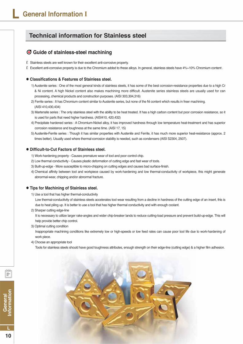
Technical information for Stainless steel
Guide of stainless-steel machining
▶ Stainless steels are well known for their excellent anti-corrosive property.
▶ Excellent anti-corrosive property is due to the Chromium added to these alloys. In general, stainless steels have 4%~10% Chromium content .
1) Austenite series : One of the most general kinds of stainless steels, it has some of the best corrosion-resistance properties due to a high Cr
& Ni content. A high Nickel content also makes machining more difficult. Austenite series stainless steels are usually used for can
processing, chemical products and construction purposes. (AISI 303,304,316)
2) Ferrite series : It has Chromium content similar to Austenite series, but none of the Ni content which results in freer machining.
(AISI 410,430,434)
3) Martensite series : The only stainless steel with the ability to be heat treated. It has a high carbon content but poor corrosion resistance, so it
is used for parts that need higher hardness. (AISI410, 420,432)
4) Precipitate hardened series : A Chromium-Nickel alloy, it has improved hardness through low temperature heat-treatment and has superior
corrosion resistance and toughness at the same time. (AISI 17, 15)
5) Austenite-Ferrite series : Though it has similar properties with Austenite and Ferrite, it has much more superior heat-resistance (approx. 2
times better). Usually used where thermal-corrosion stability is needed, such as condensers (AISI S2304, 2507).
1) Work-hardening property - Causes premature wear of tool and poor control chip.
2) Low thermal conductivity - Causes plastic deformation of cutting edge and fast wear of tools.
3) Built-up-edge - More susceptible to micro-chipping on cutting edges and causes bad surface-finish.
4) Chemical affinity between tool and workpiece caused by work-hardening and low thermal-conductivity of workpiece, this might generate
abnormal-wear, chipping and/or abnormal fracture.
1) Use a tool that has higher thermal-conductivity
Low thermal-conductivity of stainless steels accelerates tool wear resulting from a decline in hardness of the cutting edge of an insert, this is
due to heat piling up. It is better to use a tool that has higher thermal conductivity and with enough coolant.
2) Sharper cutting edge-line
It is necessary to utilize larger rake-angles and wider chip-breaker lands to reduce cutting-load pressure and prevent build-up-edge. This will
help provide better chip control.
3) Optimal cutting condition
Inappropriate machining conditions like extremely low or high-speeds or low feed rates can cause poor tool life due to work-hardening of
work piece.
4) Choose an appropriate tool
Tools for stainless steels should have good toughness attributes, enough strength on their edge-line (cutting edge) & a higher film adhesion.
Classifications & Features of Stainless steel.
Difficult-to-Cut Factors of Stainless steel.
Tips for Machining of Stainless steel.

Gen
eral In
form
ation
11
L
LGeneral Information Ⅰ
Chip Breakers for Stainless steel
Korloy’s New Grades for Stainless steel machining.
• Sharp edge for shallow depth cutting• Increase tool life through reduced chip
control friction at high speed cutting • Good surface finish of work piece
HA / Finishing
• Enhanced cutting efficiency and increase tool life due to enhanced chip flow.
• Reinforced wear resistance through adopting a high land rake angle.
• Special land design to prevent notching and enhance toughness
HS / Medium cutting
• Superior tool life at light intermittent cutting
• Better chip flow through wide chip pocket
• Prevent build-up-edge by low cutting force design
GS / Medium to Rough cutting
• Chip breaker for intermittent cutting• Unique chip breaker design provide
smooth chip control.• Strong edge line permit superior
toughness
VM / Roughing
▶ Specially designed substrate & film suitable for high-speed machining of stainless steels.▶ Superior cutting performance under conditions in moderate-speed applications for cutting
low-carbon steels and low-carbon alloy steel▶ Longer tool-life can be achieved thanks to a superior chipping-resistance design in the
grade. ▶ Obtain better cutting performance. Korloy offers a variety of combinations of chip breakers
to machine easily even in deeper depth of cut.
● NC9020, For high speed turning of Stainless steel.
● PC9030, for medium to low speed turning of Stainless steel.
● PC9530, for medium to low speed milling of Stainless steel.
▶ KORLOY New Grades for Stainless steel machinig
▶ By using an ultra fine carbide substrate, the PC9030 has a tougher substrate for moderate speed machining and intermittent cutting of Stainless steel
▶ A PVD coating is applied to this grade to enhance chipping-resistance and adhesion-resistance during machining of difficult-to-cut material
▶ Exclusive grade for stainless steel, using tougher carbide as a substrate and a PVD coated, this gives the insert superior lubrication properties.
▶ Enhance your surface finish and reduce burrs by utilizing our chip-breakers, exclusively made for Stainless steels.
▶ Tough ultra-fine carbide substrate primarily used for roughing and/or intermittent milling applications in stainless steel
▶ A PVD coating is applied to achieve better tool life in stainless steel and Ni-Cr steel applications.
▶ To reduce chipping in the cutting edge Korloy uses a tough carbide substrate and PVD coating to help prevent material build up around the cutting edges.
fn
ap

Gen
eral
In
form
atio
n
12
L
L Turning
Insert shape and terminology
Calculation formulas for machining
● Relating angles between tool and workpiece
Rake angle
Side rake angle
Rake angle
• Cutting force, Cutting heat, The effects of chip control on tool life
• (+) : Excellent machine-ability (reducing cutting force, weakening cutting edge strength)• (+) : When machining excellent machine-ability or thin workpiece.• (-) : When strong cutting edge is needed at interrupted condition or mill scale.
• (-) : Cutting edge is strong but has short tool life to make bad influence on flank wear.
• (+) : Improved chip control because chip thickness is big.
• (+) : Strong cutting edge due to distributed cutting force but chip control is bad by thin chip thickness
• (-) : Improved chip performance.
• (-) : Cutting edge is strong but has short tool life to make bad influence on flank wear.
• Only cutting edge contact with cutting face
• Affects chip control and cutting force direction
• Affects chip control and cutting force direction
• Prevent friction between cutting edge and cutting face
Relief angleSide relief angle
Cutting edge angle
Side cutting edge angle
End cutting edge angle
Relief angle
Cutting edge angle
Cutting edge inclination Terminology Function Effect
Rough Kc
Mild steelMedium carbon steelHigh carbon steelLow alloy steelHigh alloy steel Cast ironMalleable cast ironBronze, Brass
1902102401902459312070
● Cutting speed
● Surface finish
● Material removal rate
● Feed
• vc : Cutting speed (m/min)• D : Diameter (mm)
• n : Revolution per minute (min-1)• π : Circular constant(3.14)
• PKW : Power requirement [kW]• PHP : Power requirement (horse power) [HP]• vc : Cutting speed [m/min]• ap : Depth of cut [mm]
• fn : Feed per revolution [mm/rev]• kc : Specific cutting resistance [kg/mm²]• η : Machine efficiency rate (0.7~0.8)
• fn : Feed per revolution(mm/rev)• vf : Table feed (mm/min)
• n : Revolution per minute (min-1)
• Q : Material removal rate [㎤/min] • ap : Depth of cut [mm]• vc : Cutting speed [m/min] • fn : Feed per revolution [mm/rev]
vc = π × D × n (m/min) 1000
Q = vc × fn × ap 1000 Q = vc × fn × ap
1000
fn = vf (mm/rev) n
• Theoretical surface roughness
• Practical surface roughness
Rmax = fn² 1000(㎛ )
8r
Steel : Rmax × (1.5~3)Cast iron : Rmax × (3~5)
• Rmax : Profile depth(Maximum height roughness) (μ)• fn : feed (mm/rev)• r : nose radius
Pkw = Q × kc 60 ×102× η PHP = PKW
0.75
● Power requirement
End cutting edge angle
Side relief angle
Side rake angleNose radius
Relief angle
Rake angle
Cutting edge height
Shank height
Cutting edge angle
Side cutting edge angle
Shank width
Total length

Gen
eral In
form
ation
13
L
LTurning
● Machining time
T : Machining time [sec]
L : Cutting length [mm]
fn : Feed per revolution [mm/rev]
n : Revolution per minute [min]
D : Diameter of workpiece [mm]
vc : Cutting speed [m/min]
T : Machining time [sec]
L : Cutting length [mm]
fn : Feed per revolution [mm/rev]
n : Revolution per minute [min]
D1 : Maximum diameter of workpiece [mm]
D2 : Minimum diameter of workpiece [mm]
vc : Cutting speed [m/min]
N : The number of pass = (D1-D2)/d/2
T : Machining time [sec]
T1 : Machining time before the maximum rpm[sec]
L : Width of machining [mm]
fn : Feed per revolution [mm/rev]
n : Revolution per minute [min-1]
D1 : Maximum diameter of workpiece [mm]
D2 : Minimum diameter of workpiece [mm]
vc : Cutting speed [m/min]
T : Machining time [sec]
T1 : Machining time before the maximum rpm[sec]
T3 : Machining time till maximum RPM[sec]
fn : Feed per revolution [mm/rev]
n : Revolution per minute [min-1]
nmax : Maximum revolution per minute [min-1]
D1 : Maximum diameter of workpiece [mm]
D3 : Maximum diameter at maximum RPM [mm]
vc : Cutting speed [m/min]
Facing
External face machining 1
Grooving
Parting
External face machining 2
T = 60 × L × N fn × n
T = 60 × π × L × (D1 + D2) × N
2 × 1000 × fn × vc
Constant Revolution per minute
Constant cutting speed
T = 60 × L fn × n
T = 60 × π × L × D 1000 × fn × vc
Constant Revolution per minute
Constant cutting speed
T = 60 × (D1 - D2) × N 2 × fn × n
T1 = 60 × π × (D1 + D2) × (D1 - D2) × N 4000 × fn × vc
Constant Revolution per minute
Constant cutting speed
T = 60 × (D1 - D2) 2 × fn × n
T1 = 60 × π × (D1 + D2) × (D1 - D2) 4000 × fn × vc
Constant Revolution per minute
Constant cutting speed
T = 60 × D1 2 × fn × n
T1 = 60 × π × (D1 + D3) (D1 - D3) 4000 × fn × vc
T3 = 60 × D3
T1 + 2 × fn × nmax
Constant Revolution per minute
Constant cutting speed

Gen
eral
In
form
atio
n
14
L
L Turning
The affects of cutting condition
Cutting Speed’s effects
Feed
The effects of feed
Depth of cut
The effect of a depth of cut
Cutting speed
▶ The most desirable machining means short machining time, long tool life and good precision. This is the reason that proper cutting
condition for each tools should be selected according to material’s properties, hardness, shapes, the efficiency of machine.
▶ When the cutting speed increases up to 20% in an application, the tool life respectively decreases down 50%. Although inversely, if the
cutting speed increases up to 50% the tool life decreases 20%. On the other hand if cutting speed is too low (20-40m/min) Tool life shortens
due to vibration.
▶ The feed rate in turning means the progressed interval of a distance in a work piece within 1 revolution. The feed rate in a milling application
means the table feed divided by number of teeth of cutter (feed rate per tooth).
▶ When the feed rate decreases the flank wear is increased. When
the feed rate is too low, the tool life shortens radically.
▶ When the feed rate increases, the flank wear increases due to high
temperatures, however the feed rates effects tool life less than the
cutting speed. And higher feed rates improve machining efficiency.
▶ Determined by the required allowances in machining a material and the capacity the machine can tolerate.
There are cutting limits according to the different shapes and sizes of the insert.
▶ The depth of cut does not have a big influence on tool life.
▶ When the depth of cut is small the work piece is not cut but rather
rubbed. In these cases, machine off the work hardened parts that
decrease tool life.
▶ When machining a cast skin or milling scale smaller depth of cuts
usually cause chipping and abnormal wear because of hard
impurities in the surface of the work piece.
The tool life feature of P grade
NC3030
Low grade High grade
NC3120 NC3010
The tool life feature of M grade
The tool life feature of K grade
NC315K
Low grade High grade
NC6110
Low grade High grade
PC9030NC3030 NC9020Workpiece : S45C (180HB)
Tool life criterion : VB=0.2mmDepth of cut : 1.5mmFeed : 0.3mm/revHolder : PCLNR2525-M12Insert : CNMG120408Dry cutting
Workpiece : STS304 (200HB)Tool life criterion : VB=0.2mmDepth of cut : 1.5mmFeed : 0.3mm/revHolder : PCLNR2525-M12Insert : CNMG120408Dry cutting
Workpiece : GC300 (180HB)Tool life criterion : VB=0.2mmDepth of cut : 1.5mmFeed : 0.3mm/revHolder : PCLNR2525-M12Insert : CNMG120408Dry cutting
Relationship between feed and flank wear in steel turning
Relationship between depth of cut and flank wear in steel turning
Surface parts including mill scale Roughing
Cutting condition Workpiece : SNCN431Grade : ST20Cutting speed : 200m/minFeed : 0.2mm/revCutting time : 10min
Cutting condition Workpiece: SNCN431 Grade : ST20Cutting speed : 200m/minDepth of cut : 1.0mmCutting time : 10min

Gen
eral In
form
ation
15
L
LTurning
Relief angle
Side cutting edge angle
Relief angle avoids the friction between workpiece and relief face and makes cutting edge move along workpiece easily.
Side cutting edge angle has big influence on chip flow and cutting force therefore proper Side cutting edge angle is very important.
● Relationship between various relief angle and flank wear
● Side cutting edge angle and Chip thickness
• Workpiece : SNCM431(HB200)• Grade : P20• ap : 1mm• fn : 0.32mm/rev• T : 20min
• Affects 1. If relief angle is big Flank wear decreases. 2. If relief angle is big Cutting edge strength weakens. 3. If relief angle is small Chattering occurs .
• Selection system 1. Hard workpiece / When strong cutting edge is needed - Low relief angle 2. Soft workpiece / Workpiece turning to work hardening easily - High relief angle
● Side cutting edge angle and Tool life
● Side cutting edge angle and 3 cutting forces
● Side cutting edge angle and Cutting load ● Side cutting edge angle and Cutting performance
• Affects1. Big side cutting edge angle with the same feed
makes chip attaching length longer and chip thickness thinner. So that cutting forces scatter to long cutting edge therefore tool life gets longer.
2. Big side cutting edge angle for machining long bars can cause bending.
• Workpiece : SCM440(HB250)• Grade : TNGA220412• vc= 100m/min• ap= 4mm• fn= 0.45mm/rev
• Workpiece : SCM440• Grade : P20• ap : 3mm• fn : 0.2mm/rev
• Selection system 1. Deep depth of cut finishing / Long thin workpiece / Low machine rigidity - Side cutting edge angle 2. Hard and high calorific power workpiece / Roughing big workpiece / High machine rigidity - Side cutting edge angle
As side cutting edge angle is getting bigger chips are getting thinner and wider(refer to left picture). At the same feed and depth of cut with approach angle 0˚Chip thickness is the same as feed(t=fn) and chip width is equal to depth of cut (W=ap).
t1 = 0.97t, W1 = 1.04Wt2 = 0.87t, W2 = 1.15W
① Approach angle 0˚ ② Approach angle 15˚ ③ Approach angle 30˚
① “Force P is loaded.” ② “Force P is scattered to P1, P2.”
As approach angle gets bigger Back force gets bigger and feed force gets smaller.
Wear rate
Workpiece
Machining power
Chatter
How to machine
Workpiece rigidity
Machine rigidity
Specification Low
High
Easy to cut material
Small
Hard to occur
Finishing
Long thin workpiece
In case of low rigidity
High
Low
Difficult to cut material
Big
Easy to occur
Roughing
Thick workpiece
In case of high rigidity
Approach angle
Breakage
Relief angle
Flan
k w
ear

Gen
eral
In
form
atio
n
16
L
L Turning
End cutting edge angle
Nose-R
● Relationship between nose radius, feed and various surface roughness.
It affects machined surface to prevent interference between surface of workpiece and insert.
1. Nose-R affects not only surface roughness but strength of cutting edge.
2. In general, It’s desirable that Nose-R is 2~3 times bigger than feed.
Affects1. If end cutting edge angle reduces cutting edge get stronger but cutting heat generated by machining increases.
2. Small end cutting edge angle can cause chattering due to the increases cutting force.
● Nose R and surface finish ● Nose R and tool life ● Nose R and wear of tool
• Workpiece : SNCM439, HB200• Grade : P20• vc = 120m/min, ap = 0.5mm
• Workpiece : SCM440, HB280• Grade : P10• vc = 100m/min, ap = 0.5mm• fn = 0.3mm/rev
• Workpiece : SNCM439, HB200• Grade : P10• vc = 140m/min, ap = 2mm• fn = 0.2mm/rev, T = 10min
Surface finish(μ)
Nose-R(mm)
Tool life(the number of impact)
Nose-R(mm)
Flank wear (mm)
Nose-R(mm)
Affects of Nose-R 1. Big Nose-R improves surface finish.
2. Big Nose-R improves cutting edge strength.
3. Big Nose-R reduces flank wear and crater wear.
4. Too big Nose-R causes chattering due to increased cutting force.
Selection system 1. For finishing with small depth of cut / long and thin workpiece /
When machine power is low - Small Nose-R
2. For applications that need strong cutting edge such as intermittent
and machining mill scale / For roughing of big workpiece / When
the machine power is strong eough - Big Nose-R
Nose “R” Feed(mm/rev)
0.15
0.4 0.8 1.2
0.26
0.46

Gen
eral In
form
ation
17
L
LTurning
Cutting edge shape and the affects
● Rake angle
Rake angle has big influence on cutting force, chip flow and tool life.
α = -5°
α = 15°
α = 25°
α = -5°
α = 15°
α = 25°
• Affects 1. High rake angle results in good suface finish. 2. As the rake angle increases by 1° Machining power decreases
by 1%. 3. High rake angle weakens cutting edge.
• Selection system 1. For hard workpiece / For applications that need strong
cutting edge such as interrupted and machining mill scale - Low rake angle 2. For soft workpiece / Easy to cut material / When the rigidity of
machine power and workpiece is low - High rake angle
● Rake angle and the direction of chip flow
● Selection of inserts and tool holder Listed below is the basic factors and choose B according to A.
γ :nega(-)λ :nega(-)
γ :posi(+)λ :nega(-)
γ :posi(+)λ :posi(+)
γ :nega(-)λ :posi(+)
Rake angle : γ Side rake angle : λ
In order to prevent machined surface from damages Avoid nega,posi combination. γ :nega(-) λ :posi(+)
A : Basic factors B : Selection system
Nowadays, It’s very difficult to select the best tools in complicating tooling system and various cutting conditions.
However, It can be simplified by classifying basic factors below.
· Workpiece material
· Workpiece shape
· Workpiece size
· Hardness of workpiece
· Surface roughness of workpiece (before machining)
· Surface finish required
· Type of lathe machine
· Condition of lathe machine (rigidity, power etc)
· Horse power of machine
· Clamping method of workpiece
① Select as big approach angle as possible.
② Select as big shank as possible.
③ Select as strong cutting edge of insert as possible
④ Select as big nose radius as possible
⑤ In finishing, Select the insert using many corners
⑥ Select as small insert as possible
⑦ Cutting speed should be determined carefully according to cutting conditions
⑧ Select as deep depth of cut as possible
⑨ Select as fast feed as possible
⑩ Cutting condition should be determined within chip breaker application ranges.
Selecting proper tools
Relief angle Relief angle

Gen
eral
In
form
atio
n
18
L
L Turning
Tool Failure
Crater wear
• Improper grade• Excessive cutting condition
• Improper grade• Excessive feed• Shorten cutting edge strength• Insufficient rigidity of holder
• Improper grade• Excessive cutting condition• High cutting temperature
• Expansion and shrinking by cutting temperature • Improper grade (*Specially milling operation)
• Improper grade• Excessive feed• Shorten cutting edge strength• Insufficient rigidity of holder
• Surface hardened workpiece• Friction due to bad chip geometry (Generate vibration)
• Deposition on cutting edge• Bad chip control
• Unusable condition due to wear off the most parts of cutting edge by progress of wear
• Slow cutting speed• Sticky materials
• Reduce the feed rate.• Reduce the depth of cut.• Select a tougher grade.• Select a stronger chipbreaker.• Select a thicker insert.
• Increase cutting speed.• Use more positive rake geometry.• Use tougher grade
• Choose harder grade• Decrease cutting condition
• Choose tougher grade• Decrease feed• Apply to large honed or chamfered edge• Choose bigger size holder
• Choose harder grade• Decrease cutting condition • Choose grade wich heat conductivity are big
• When the hardness of workpiece is too high compare with tool• When machinig surface hardened workpiece• Improper grade• Excessive cutting speed• Too small relief angle• Too low feed
• Choose harder grade• Decrease cutting speed• Choose lager relief angle• Increase feed
• Apply to dry cutting (In case of wet cutting, use enough coolant)• Choose tougher grade
• Choose tougher grade• Decrease feed• Apply to large honing or chamfer edge• Choose bigger size holder
• Choose harder grade• Improve chip control form large rake angle
• Improve cutting performance fromd large rake angle• Apply to chip pocket with big size
Fracture
Plastic deformation
Wear on nose radius(Flank wear)
Thermal crack
Chipping
Notch wear
Flaking
Complete breakage
Built-up edge
Cause Solution
Trouble shooting

Gen
eral In
form
ation
19
L
LTurning
Insert precision is variable
Workpiece, Separation of tool
Flank wear increase
Cutting condition is improper
Cutting edge chipping
Adhesion, built-up edge
Improper cutting conditions
Vibration, chattering
Improper cutting conditions
Improper cutting conditions
Improper cutting conditions
Improper cutting conditions
●
●
●
●
●
●
●
●
●
●
●
●
●
●
●
●
●
●
●
●
●
●
●
●
●
●
●
●
●
●
●
●
●
●
●
CausesTroubles
Solution
Cutting conditions
Cu
ttin
g s
peed
Feed
Dep
th o
f cu
t
Co
ola
nt
Ch
ip b
reaker
valu
atio
n
Rake a
ng
le
No
se r
ad
ius
Sid
e c
utt
ing
ed
ge a
ng
le
Cu
ttin
g e
dg
e s
tren
gth
H
on
ing
Imp
rovin
g in
sert
pre
cis
ion
M
cla
ss
G c
lass
Imp
rovin
g h
old
er
rig
idity
Cla
mp
ing
wo
rkp
iece
Ho
lder
overh
an
g
Mach
ine v
ibra
tio
n
Sele
ct h
ard
er
gra
de
Sele
ct to
ug
her
gra
de
Selec
t bet
ter h
eat-i
mpa
ct
resis
tanc
e gra
de
Sele
ct b
ette
r adh
esio
n re
sist
ance
gra
de
Selecting insert grade Tool shape Machine clamping
: Increase : Decrease : use : Correct use
Poor precision Unstable machining size
Cutting edge back thrust is big It’s necessary to adjust because machining precision changes during operation.
Poor surface roughness for finishing Criterion of tool life.
Cutting heat generation Poor machining precision and short tool life by cutting heat
burr, chipping, nap steel, aluminum (burr)
Cast iron (Weak chipping)
Soft steel (nap)
Wet cutting
Wet cutting
Wet cutting
Wet cutting
Wet cutting
Wet cutting
●
●
●
●
KS B0813
Flank wear width
0.2mm
0.4mm
0.7mm
1~1.25mm
Precision light cutting , Finishing in nonferrous alloy
Machining special steel
General cutting in cast iron, steel etc
General cutting in cast iron, steel etc
Depth of crater wear In general 0.05~0.1 mm
ISO(B8688)
Complete breakageFlank wear width VB = 0.3mmVBmax = 0.5mmCrater wear width KT = 0.06+0.3fmm (f:mm/rev)Criterion by surface roughness 1, 1.6, 2.5, 4, 6.3, 10 Ra
Machining special steelEven flank wear of cemented carbides, Ceramic toolUneven flank wearCemented carbides toolWhen surface roughness is important
Tool life criterion Application
Types of tool failure and trouble shooting
Tool life criterion
Weakened cutting force by increasing wear of tool
Improper tool and shape of cutting edge
Improper tool and shape of cutting edge
Wear on the tool, improper shape of cutting edge
Wear on the tool, improper shape of cutting edge
Wear on the tool, improper shape of cutting edge

Gen
eral
In
form
atio
n
20
L
L Milling
Milling cutter shape and designation
Tool failure Symbol
Axial rake angle Chip flow direction, Adhesion
Affecting on thrust
Chip thickness, Determines flow direction
Effective rake angle
Determines chip flow direction
Controlling surface roughnessfor finishing
Controlling cutting edge strength, tool life and chattering
(+) : Better cutting. Preventing adhesion, Weakening cutting edge strength.
(-) : Cutting edge strength increases, easy to adhere
(+) : Good chip flow, cutting force decreases, Corner edge strength weakens
(+) : Chip thickness become thinner, cutting force could be reduced.
-
-
-
(-) : Surface roughness improves
A.R
R.R
A.A
I.A
F.A
R.A
T.A
Radial rake angle
Approach angle
True rake angle
Cutting edge inclination angle
Face angle
Relief angle
1
2
3
4
5
6
7
Function Effects
The terminology and functions of cutting edge angle
Locater
Setting ring
Face angle
Radial rake angle
Major cutting edge
Chamfer
AR : Axial rake angle (-90°<AR<90°) RR : Radial rake angle (-90°<RR<90°) AA : Approach angle (0°<AA<90°) TA : True rake angle (-90°<TA<90°) IA : Cutting edge inclination angle (-90°<IA<90°) FA : Face angle (-90°<FA<90°)
Minor cutting edge
Axial-rake angle
Depth of key way
Diameter of cutter body
Diameter of flange
Width of key way
Approach angle
Height of cutter
Cutting edge inclination angle
Radial relief angle
True rake angle
Face reliefChip pocket
Screw for angle wedge
Diameter of cutter
Part A
Back ring

Gen
eral In
form
ation
21
L
LMilling
Features by combination of rake angle
Major cutting formulas
• Weak cutting edge strength.• Only single sided inserts are available (No economical).• Machine and cutter need enough power
and rigidity.
Double positive angle Double negative angle Posi - Negative angle Nega - Positive angle
Use
Ad
van
tag
esDi
sadv
antag
es
• General machining of steel, cast iron, stainless steel• Machining soft steel that brings about built-up edge easily• Machining material having tendency to
poor surface roughness
• Under interrupted cutting condition• Roughing of cast iron and steel
• Machining difficult to cut material• Roughing with deep depth of cut and
wide width of cut in steel and cast iron
• Chip flows to center of cutter body
-
• As for tough workpiece material It prevents built-up edge to improve surface roughness.
• Low cutting load and better machinability
• Strong cutting edge.• Roughing of workpiece that has bad surface
condition containing sand, mill scale• Double sided inserts can be
applied(Economical).• Good chip control.
• Good chip flow and machinability.• Suitable for machining of difficult-to-cut
material • Un-even partition clamping prevents
chattering
• Machine and cutter need enough power and rigidity.
• Only single sided inserts are available (No economical)
• Since the chips flows toward the center of cutter. Chips scratch on machined surface.
• Bad chip flow.• No economical
Cutting speed
Power requirement
Machining time
True rake angle / Cutting edge inclination angle
Feed
Chip removal amount
•vc : Cutting speed (m/min) •D : Diameter of tool (mm) •n : Revolution per minute (min-1)•π : Circular constant (3.14)
•fz : Feed per tooth (mm/t) •vf : Feed per minute (mm/min) •n : Revolution per minute (min-1)•z : Number of tooth
•Q : Chip removal amount (cm3/min) •L : Width of cut (mm) •vf : Table feed (mm/min)•ap : Depth of cut (mm)
•Pc : Power requirement (kW)•H : Horse power requirement (hp) (mm/min)•Q : Chip removal amount (cm3/min)•kc : Specific cutting resistance (kgf/mm3)•η : Machine efficiency rate (0.7~0.8)
•T : Machining time (sec)•Lt : Total length of table feed
(mm)(=Lw+D+2R)•Lw : The length of workpiece (mm)•D : The diameter of cutter body (mm)•vf : Table feed (mm/min) •R : Relief length (mm)
True rake angle tan(T) = tan(R) x cos(AA) + tan(A) x sin(C)Cutting edge inclination angle tan(I) = tan(A) x cos(AA) - tan(R) x sin(C)
vc = π·D·n (m/min) 1000
fz = vf
(mm/t) z·n
Q = L×vf×ap ( /min)
1000
Pkw = Q×kc 60×102×η Php = Pkw
0.75
T = 60 x Lt (sec) vf
Gen
eral
In
form
atio
n
22
L
L Milling
WorkpieceTensile strength
(kg/ ) and hardness 0.1
(mm/t)0.2
(mm/t)0.3
(mm/t)0.4
(mm/t)0.6
(mm/t)
Specific cutting resistance according to various feed kc(MPa)
D : External diameter of cutter bodyD1 : Width of workpiece d : Projected part of cutter bodyE : Engage angleδ : Ratio of cutter body and width of workpiece(D:D1)
Length of workpiece
Small cutter movement
Medium cutter movement
Big cutter movement
smallmedium
big
Selection by machine rigidity
Selection by machine rigidity
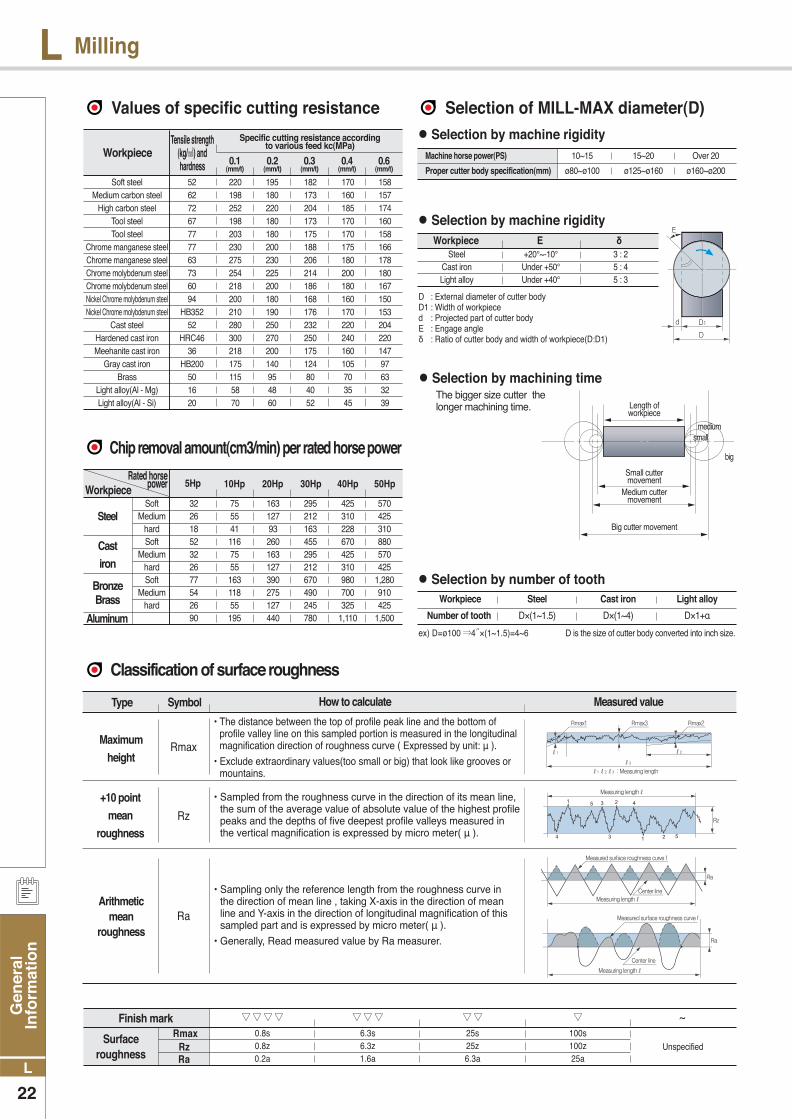
The bigger size cutter the longer machining time.
Selection by number of tooth
Workpiece E δ
ex) D=ø100 4 ×(1~1.5)=4~6 D is the size of cutter body converted into inch size.
Cast
iron
Steel
Bronze Brass
Aluminum
Soft 32 75 163 295 425 570 Medium 26 55 127 212 310 425 hard 18 41 93 163 228 310 Soft 52 116 260 455 670 880 Medium 32 75 163 295 425 570 hard 26 55 127 212 310 425 Soft 77 163 390 670 980 1,280 Medium 54 118 275 490 700 910 hard 26 55 127 245 325 425 90 195 440 780 1,110 1,500
Workpiece 10Hp 20Hp 30Hp 40Hp 50Hp5HpRated horse
power
Machine horse power(PS) 10~15 15~20 Over 20
Proper cutter body specification(mm) ø80~ø100 ø125~ø160 ø160~ø200
Selection by machining time
Steel +20°~-10° 3 : 2 Cast iron Under +50° 5 : 4 Light alloy Under +40° 5 : 3
Type Symbol How to calculate Measured value
Maximum
height
+10 point
mean
roughness
Arithmetic mean
roughness
• The distance between the top of profile peak line and the bottom of profile valley line on this sampled portion is measured in the longitudinal magnification direction of roughness curve ( Expressed by unit: μ ).
• Exclude extraordinary values(too small or big) that look like grooves or mountains.
Rmax
Rz
Ra
• Sampled from the roughness curve in the direction of its mean line, the sum of the average value of absolute value of the highest profile peaks and the depths of five deepest profile valleys measured in the vertical magnification is expressed by micro meter( μ ).
• Sampling only the reference length from the roughness curve in the direction of mean line , taking X-axis in the direction of mean line and Y-axis in the direction of longitudinal magnification of this sampled part and is expressed by micro meter( μ ).
• Generally, Read measured value by Ra measurer.
Finish mark Rmax
RzRa
Surface roughness
0.8s0.8z0.2a
6.3s6.3z1.6a
25s25z6.3a
100s100z25a
Unspecified
~
Soft steel 52 220 195 182 170 158 Medium carbon steel 62 198 180 173 160 157 High carbon steel 72 252 220 204 185 174 Tool steel 67 198 180 173 170 160 Tool steel 77 203 180 175 170 158 Chrome manganese steel 77 230 200 188 175 166 Chrome manganese steel 63 275 230 206 180 178 Chrome molybdenum steel 73 254 225 214 200 180 Chrome molybdenum steel 60 218 200 186 180 167 Nickel Chrome molybdenum steel 94 200 180 168 160 150 Nickel Chrome molybdenum steel HB352 210 190 176 170 153 Cast steel 52 280 250 232 220 204 Hardened cast iron HRC46 300 270 250 240 220 Meehanite cast iron 36 218 200 175 160 147 Gray cast iron HB200 175 140 124 105 97 Brass 50 115 95 80 70 63 Light alloy(Al - Mg) 16 58 48 40 35 32 Light alloy(Al - Si) 20 70 60 52 45 39
Workpiece Steel Cast iron Light alloy
Number of tooth D×(1~1.5) D×(1~4) D×1+α
Values of specific cutting resistance
Chip removal amount(cm3/min) per rated horse power
Classification of surface roughness
Selection of MILL-MAX diameter(D)

Gen
eral In
form
ation
23
L
LMilling
CausesTrouble
SolutionsCutting conditions
Cutting speed
Depth of cut
Feed CoolantApproach
angleRelief angle
Rake angle
Nose radius
Chattering at cutting
edgeToughness Hardness
Tool shape Insert grade
Flank wear
Crater wear
Chipping
Built-up edge
Chattering
• Improper insert grade• Improper cutting conditions• Chattering
• Improper cutting conditions• Improper insert grade
• Lack of insert toughness• Excessive feed• Excessive cutting load
• Improper cutting conditions • Improper cutting edge shape• Improper insert grade
• Improper cutting conditions • Lack of number of cutting teeth• Improper cutting edge shape • Bad chip flow• Unstable workpiece clamping
• Built-up edge • Improper cutting conditions • Chattering • Bad chip flow
• Improper cutting conditions • Improper insert grade
Poor surface finish
Thermal crack
• Improper insert grade • Excessive cutting load • Bad chip flow • Chattering • Excessive overhang
Fracture
Machine efficiency rate (η)
Power transmission mode Efficiency rate (E) Reference Principal axis direct connection driving 0.90
Belt driving 0.85 Double connection : 0.85 × 0.85 0.70
Starting driving 0.75
Oil pressure driving 0.60~0.90
: Increase : Decrease : use : Correct use
Trouble shooting for milling
General formulas for milling

Gen
eral
In
form
atio
n
24
L
L Tapers
0 1°29′27″ 9.045 3 9.201 6.442 50 53 6 - 4 0.2
1 1°25′43″ 12.065 3.5 12.230 9.396 53.5 57 9 M6 16 5 0.2
2 1°25′50″ 17.780 5 18.030 14.583 64 69 14 M10 24 5 0.2
3 1°26′16″ 23.825 5 24.076 19.759 81 86 19 M12 28 7 0.6
4 1°29′15″ 31.267 6.5 31.605 25.943 02.5 109 25 M16 32 9 1
5 1°30′26″ 44.399 6.5 4.741 37.584 129.5 136 35.7 M20 40 9 2.5
6 1°29′36″ 63.348 8 63.765 53.859 182 190 51 M24 50 12 4
7 1°29′22″ 83.058 10 83.578 70.058 250 260 65 M33 80 18.5 5
0 1°29′27″ 9.045 3 9.201 6.104 56.5 59.5 6.0 3.9 6.5 10.5 4 1
1 1°25′43″ 12.065 3.5 12.240 8.972 62.0 65.5 8.7 5.2 8.5 13.5 5. 1.2
2 1°25′50″ 17.780 5 18.030 14.034 75.0 80.0 13.5 6.3 10 16 6 1.6
3 1°26′16″ 23.825 5 24.076 19.107 94.0 99.0 18.5 7.9 13 20 7 2
4 1°29′15″ 31.267 6.5 31.605 25.164 117.5 124.0 24.5 11.9 16 24 8 2.5
5 1°30′26″ 44.399 6.5 4.741 36.531 149.5 156.0 35.7 15.9 19 29 10 3
6 1°29′36″ 63.348 8 63.765 52.399 210.0 218.0 51.0 19.0 27 40 13 4
7 1°29′22″ 83.058 10 83.578 68.186 286.0 296.0 66.8 28.6 35 54 19 5
MT No. Taper Taper angle(α) D a D1 d1 ℓ1 ℓ2 d2 b c e R r
19.2121
1
1
1
1
1
1
20.047
20.020
19.922
19.2541
19.002
19.180
19.231
19.2121
1
1
1
1
1
1
1
20.047
20.020
19.922
19.254
19.002
19.180
19.231
MT No. Taper Taper angle(α) D a D1 d ℓ1 ℓ2 d1 d2 k t r
4 10.221 2.4 10.321 8.890 8.0 31.0 34.2 2 0.2 - - 5 13.286 2.4 13.386 11.430 10.0 44.4 46.8 3 0.2 - - 6 15.229 2.4 15.330 12.700 11.0 60.0 62.7 3 0.2 M 8(1/4) 20 7 18.424 2.4 18.524 15.240 14.0 76.2 78.6 4 0.2 M10(3/8) 24 8 22.828 3.2 22.962 19.090 17.0 90.5 93.7 4 0.6 M12(1/2) 28 9 27.104 3.2 27.238 22.863 21.0 101.6 104.8 4 0.6 M12(1/2) 28 10 32.749 3.2 32.887 26.534 24.0 144.5 147.7 5 1.0 M16(5/8) 32 11 38.905 3.2 39.039 31.749 29.0 171.4 174.6 5 1.0 M16(5/8) 32 12 45.641 3.2 45.774 38.103 35.0 181.0 184.2 6 2.5 M20(3/4) 40 13 52.654 3.2 52.787 44.451 41.0 196.8 200.0 6 3.0 M20(3/4) 40 14 59.533 3.2 59.666 50.800 47.0 209.6 212.8 7 4.0 M24(1) 40 15 66.408 3.2 66.541 57.150 53.0 222.2 225.4 7 4.0 M24(1) 50 16 73.292 3.2 73.425 63.500 59.0 35.0 238.2 8 5.0 M30(11/8) 60
B&S No. D a D1 d d1 ℓ1 ℓ2 t r d2 K
B&S No.
4 10.221 2.4 10.321 8.458 8.1 42.1 44.5 5.5 8.7 14.4 7.9 1.3 5 13.286 2.4 13.386 10.962 10.7 55.6 58.0 6.3 9.5 16.2 7.9 1.5 6 15.229 2.4 15.330 12.167 11.7 73.0 75.4 7.1 11.1 18.0 7.9 1.5 7 18.424 2.4 18.524 14.675 14.2 89.7 92.1 7.9 11.9 20.3 9.5 1.8 8 22.828 3.2 22.962 18.453. 18.0 104.8 108.0 8.7 12.7 22.0 9.5 2.0 9 28.104 3.2 27.238 22.200 21.8 117.5 120.7 9.5 14.3 25.4 11.1 2.5 10 32.749 3.2 32.887 25.751 25.7 162.7 165.9 11.1 16.7 28.1 11.1 2.8 11 38.905 3.2 39.039 30.985 30.7 189.7 192.9 11.1 16.7 30.0 12.7 3.3 12 45.641 3.2 45.774 37.246 37.1 201.6 204.8 12.7 190 32.5 12.7 3.8 13 52.654 3.2 52.787 43.589 43.4 217.5 220.7 12.7 19.0 35.7 15.9 4.3 14 59.533 3.2 59.666 49.841 49.8 232.6 235.8 14.2 21.4 41.2 19.0 4.8 15 66.408 3.2 66.541 56.186 56.1 245.3 248.5 14.2 21.4 44.4 22.2 5.3 16 73.292 3.2 73.425 62.441 62.2 260.4 263.6 15.8 23.8 50.0 25.4 5.8
D a D1 d1 d2 ℓ1 ℓ2 b c e R r
Morse taper (Tang type)
Morse taper (Screw type)
Brown sharp taper (Screw type)
Brown sharp taper (Tang type)

Gen
eral In
form
ation
25
L
LTapers
35 53 43 22 10 14.6 2 38.1 13 56.5 M12×1.75 16.1 19.6 21.62
40 63 52 25 10 16.6 2 44.45 17 65.4 M16×2 16.1 22.6 25.3
45 85 73 30 12 21.2 3 57.15 21 82.8 M20×25 19.3 29.1 33.1
50 100 85 35 15 23.2 3 69.85 25 101.8 M24×3 25.7 35.4 40.1
60 155 135 45 20 28.2 3 107.95 31 161.8 M30×3.5 25.7 60.1 60.7
(mm)
D1 D2 t1 t2 t3 t4 d1 d3 L M b1 t5 d5BT No.
HSK shank (DIN 69893)
26 42 18 3.75 2 15.5 25 5 11 7.5 4.5 14.13 10 10 23 3 1 19 1
26 42 18 3.75 28.5 20 32 6.3 14.7 10 6 18.13 10 12 24.5 3 1 21 1.2
29 45 20 3.75 44 31.5 50 10 24 15 10 28.56 12.5 16 28 3 1.5 24 2
10.54 12 14 50 38 36.90 42 43 59.3 7 26 32 29 M16X1 10 6.8 6.8 13.997 7.648
12.5 16 14 63 48 46.53 53 55 72.3 7 34 40 37 M18X1 12 8 8.4 17.862 9.25
20 20 14 100 75 72,80 85 92 109.75 7 53 63 58 M24X1.5 16 12 12 27.329 15.00
HSK No. b1 b2 b3 d1 d2 d3 d4 d5 d6 d7 d8 d9 d10 d11 d12 d13 d14 a1 a2
50
63
100
50
63
100
(mm)
HSK No.
(mm)
1.5 2.38 6 0.5 1 2 6
1.5 3 8 0.6 1.5 3 8
2 3 12 1 1.5 3 10
f1 f2 f3 f4 b1 b2 L1 L2 L3 L4 L5 L6 L7 L8 L9 L10 L11 L12 r1 r2 r3 r4 r5 r6 r7 r8
Dimensions D D1 L ℓ1 M ℓ2 ℓ3 a t b
30 31.750 17.40 70 20 24 50 1.6 15.9 6
40 44.450 25.32 95 25 30 60 1.6 15.9 22.5
50 69.850 39.60 130 25 45 90 3.2 25.4 35
60 107.950 60.20 210 45 56 110 3.2 25.4 60
(mm)
NT No.
1 4
4
4
4
1
3
1
1
2
4
- 0.29- 0.36
- 0.30- 0.384
- 0.31- 0.41
- 0.34- 0.46
3
Bottle grip taper
Standard taper of American milling machineUNC
UNC
UNC
UNC 1
21 ″
85 ″
″
411 ″
Gen
eral
In
form
atio
n
26
L
L Tapers
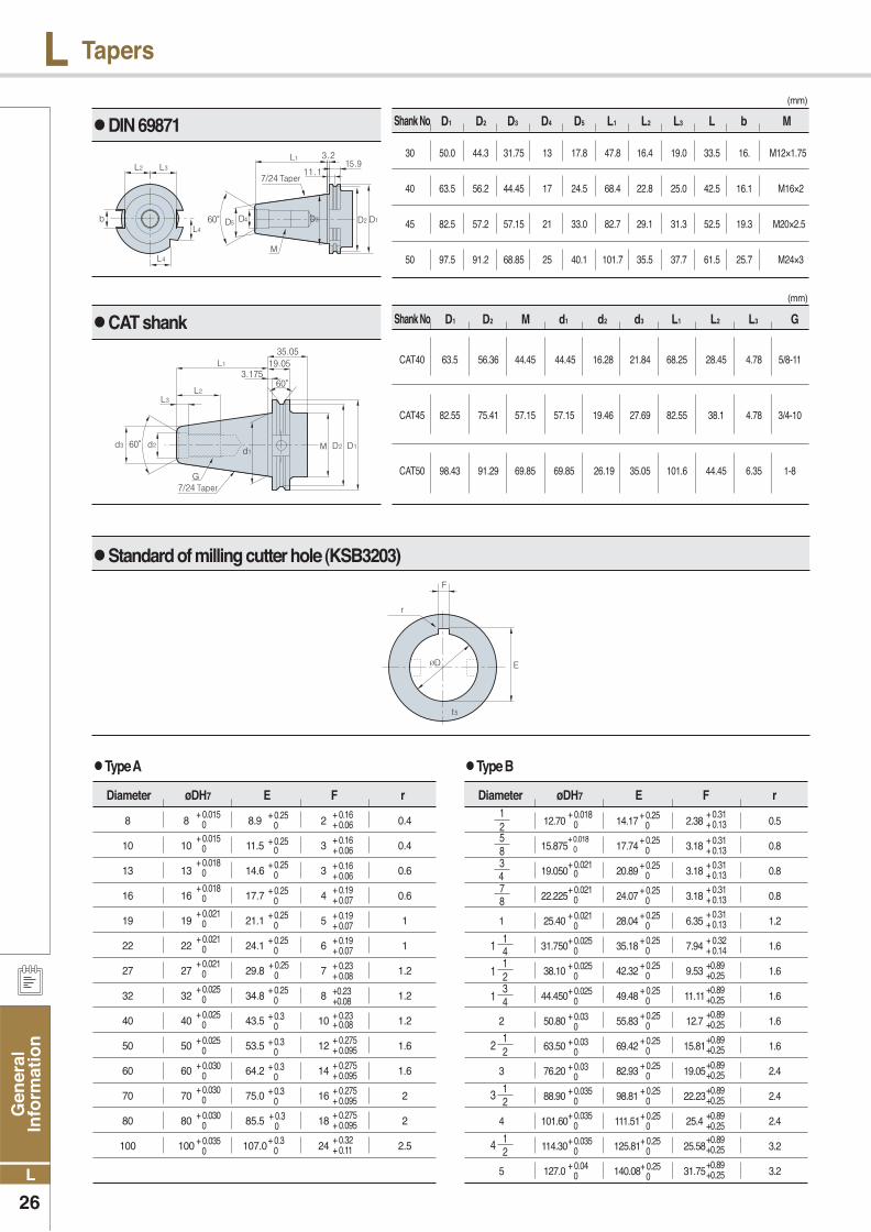
Standard of milling cutter hole (KSB3203)
(mm)
Shank No D1 D2 D3 D4 D5 L1 L2 L3 L b M
30 50.0 44.3 31.75 13 17.8 47.8 16.4 19.0 33.5 16. M12×1.75
40 63.5 56.2 44.45 17 24.5 68.4 22.8 25.0 42.5 16.1 M16×2
45 82.5 57.2 57.15 21 33.0 82.7 29.1 31.3 52.5 19.3 M20×2.5
50 97.5 91.2 68.85 25 40.1 101.7 35.5 37.7 61.5 25.7 M24×3
(mm)
Shank No D1 D2 M d1 d2 d3 L1 L2 L3 G
CAT40 63.5 56.36 44.45 44.45 16.28 21.84 68.25 28.45 4.78 5/8-11
CAT45 82.55 75.41 57.15 57.15 19.46 27.69 82.55 38.1 4.78 3/4-10
CAT50 98.43 91.29 69.85 69.85 26.19 35.05 101.6 44.45 6.35 1-8
12.70 14.17 2.38 0.5
15.875 17.74 3.18 0.8
19.050 20.89 3.18 0.8
22.225 24.07 3.18 0.8
1 25.40 28.04 6.35 1.2
31.750 35.18 7.94 1.6
38.10 42.32 9.53 1.6
44.450 49.48 11.11 1.6
2 50.80 55.83 12.7 1.6
63.50 69.42 15.81 1.6
3 76.20 82.93 19.05 2.4
88.90 98.81 22.23 2.4
4 101.60 111.51 25.4 2.4
114.30 125.81 25.58 3.2
5 127.0 140.08 31.75 3.2
8 8 8.9 2 0.4
10 10 11.5 3 0.4
13 13 14.6 3 0.6
16 16 17.7 4 0.6
19 19 21.1 5 1
22 22 24.1 6 1
27 27 29.8 7 1.2
32 32 34.8 8 1.2
40 40 43.5 10 1.2
50 50 53.5 12 1.6
60 60 64.2 14 1.6
70 70 75.0 16 2
80 80 85.5 18 2
100 100 107.0 24 2.5
Type A
Diameter øDH7 E F r+ 0.015 0
+ 0.015 0
+ 0.018 0
+ 0.018 0
+ 0.021 0
+ 0.021 0
+ 0.021 0
+ 0.025 0
+ 0.025 0
+ 0.025 0
+ 0.030 0
+ 0.030 0
+ 0.030 0
+ 0.035 0
+ 0.25 0
+ 0.25 0
+ 0.25 0
+ 0.25 0
+ 0.25 0
+ 0.25 0
+ 0.25 0
+ 0.25 0
+ 0.3 0
+ 0.3 0
+ 0.3 0
+ 0.3 0
+ 0.3 0
+ 0.3 0
+ 0.16+ 0.06
+ 0.16+ 0.06
+ 0.16+ 0.06+ 0.19+ 0.07
+ 0.19+ 0.07+ 0.19+ 0.07
+ 0.23+ 0.08
+0.23+0.08+ 0.23+ 0.08
+ 0.275+ 0.095
+ 0.275+ 0.095
+ 0.275+ 0.095+ 0.275+ 0.095+ 0.32+ 0.11
Type B
Diameter øDH7 E F r+ 0.018 0
+ 0.018 0
+ 0.021 0
+ 0.021 0
+ 0.021 0
+ 0.025 0
+ 0.025 0
+ 0.025 0
+ 0.03 0
+ 0.03 0
+ 0.03 0
+ 0.035 0
+ 0.035 0
+ 0.035 0
+ 0.04 0
+ 0.25 0
+ 0.25 0
+ 0.25 0
+ 0.25 0
+ 0.25 0
+ 0.25 0
+ 0.25 0
+ 0.25 0
+ 0.25 0
+ 0.25 0
+ 0.25 0
+ 0.25 0
+ 0.25 0
+ 0.25 0
+ 0.25 0
+ 0.31+ 0.13
+ 0.31+ 0.13+ 0.31+ 0.13+ 0.31+ 0.13+ 0.31+ 0.13
+ 0.32+ 0.14+0.89+0.25+0.89+0.25+0.89+0.25
+0.89+0.25
+0.89+0.25
+0.89+0.25
+0.89+0.25+0.89+0.25
+0.89+0.25
21
85
43
87
41
21
34
1
1
1
2
3
4
21
21
21
DIN 69871
CAT shank

Gen
eral In
form
ation
27
L
LEndmills
-Excellent -Good
Shank diameter
Cutting length
Diameter
Shank length
Total length
Peripheral Cutting edge
Helix angle
Concavity angle
The 2nd end relief
The 3rd end relief
End Cutting edge
Coner
The 2nd relief angle
The 3rd relief angle
Features of number of flute
vc =
vf= n×fn or n×fz×z
vc : Cutting speed(m/min)π : Circular constant (3.141592)D : Endmill diameter(mm)n : Revolution per minute(min-1)
π×D×n1000 n =
1000×vcπ×D
fn =vfn fz = or
fnz
vfn×z
Calculations of feed speed
44mm2 46mm2 48mm2
56% 58% 61%
Usages
Shape
RatioCross section
AdvantagesDisadvantages
Good chip flowWeak rigiditySide facing, GroovingMulti-functional
Good chip flow Difficult to measure external diameterSide facing, Grooving Medium, finishing
High rigidityBad chip flowSide cuttingFinishing
Affection of number of flute
Major featuresSpecification 2 flutes 4 flutes
Surface finish
Chip control
Grooving
Side facing
Tool rigidityTorsional rigidity
Bending rigidity
Surface roughness
Machining precision
Chip clogging
Chip evacuation
Chip evacuation
Grooving
Surface finish
Vibration
Cross section shape
General endmills High speed endmills
Features Cross section shape Features
- Applied for Low speed, High depth of cut, Low feed - Low hardness workpiece(general steel, cast iron)
- Applied for high speed, low depth of cut, high feed - Useful for hardened workpiece such as die steel
Calculations of Cutting speed
2 flutes (IFE2100)Ø10mm 3 flutes (IFE3100) 4 flutes (IFE4100)
Endmill’s shape and names
The comparison according to number of flute
The differences between general endmills and high speed endmills
vf : Feed speed(m/min)fn : Feed per revolution(mm/rev)fz : Feed per flute (mm/t)z : Number of flute
Calculations of cutting condition Ball endmills cutting speed calculation formulas
Deff = D×sin β±arccos
Deff = 2 × DXap-ap²
vc×1000
D×πRevolution per minute
Cutting speed
Feed per tooth
Feed per revolutionFeed speedChip removal rate
Effective diameter of Ball Endmill
n =
D×π×n1000vc =
vfz×n
fz =
fn = fz × zvf = fz × z × nQ = ae × ap × vf
[ ]
Calculation Table
( ) D-2ap
D

Gen
eral
In
form
atio
n
28
L
L Endmills
The affection of flute length
Spindle revolution conversion table(RPM) - external diameter
• Aspect ratio
• ℓ/d
• Ex) 3D, 15D, 22D
• Deformation rate is reaction force against external force.
• Proportional to the cube of length
• Set flute length and overall length as short as possible
• The more flute the better rigidity
• When flute width rate is narrower drill’s rigidity is higher.
δ = Pℓ3
3EI
Expression of aspect ratio Deformation rate according to length
• ℓ 2ℓ
• δ1 δ1 = 8δ1 = δ2
δ = Deformation volume ℓ= Length of cut I = Inertia moment ( )
P = Cutting force E = Elasticity coefficient Ι=
64πd4
0.2
0.3
0.4
0.5
0.6
0.7
0.8
0.9
1
1.5
2
2.5
3
3.5
4
4.5
5
5.5
6
6.5
7
7.5
8
8.5
9
9.5
10
11
12
13
14
15
16
17
18
19
20
21
22
23
24
25
20 30 40 50 60 70 80 90 100 120 140 150 180 200 250 300
Cutting speed (vc, m/min)External
vc
31,831
21,221
15,915
12,732
10,610
9,095
7,958
7,074
6,366
4,244
3,183
2,546
2,122
1,819
1,592
1,415
1,273
1,157
1,061
979
909
849
796
749
707
670
637
579
531
490
455
424
398
374
354
335
318
303
289
277
265
255
47,746
31,831
23,873
19,099
15,915
13,642
11,937
10,610
9,549
6,366
4,775
3,820
3,183
2,728
2,387
2,122
1,910
1,736
1,592
1,469
1,364
1,273
1,194
1,123
1,061
1,005
955
868
796
735
682
637
597
562
531
503
477
455
434
415
398
382
63,662
42,441
31,831
25,465
21,221
18,189
15,915
14,147
12,732
8,488
6,366
5,093
4,244
3,638
3,183
2,829
2,546
2,315
2,122
1,959
1,819
1,698
1,592
1,498
1,415
1,340
1,273
1,157
1,061
979
909
849
796
749
707
670
637
606
579
554
531
509
79,577
53,052
39,789
31,831
26,526
22,736
19,894
17,684
15,915
10,610
7,958
6,366
5,305
4,547
3,979
3,537
3,183
2,894
2,653
2,449
2,274
2,122
1,989
1,872
1,768
1,675
1,592
1,447
1,326
1,224
1,137
1,061
995
969
884
838
796
758
723
692
663
637
95,493
63,662
47,746
38,197
31,831
27,284
23,873
21,221
19,009
12,732
9,549
7,639
6,366
5,457
4,775
4,244
3,820
3,472
3,183
2,938
2,728
2,546
2,387
2,247
2,122
2,010
1,910
1,736
1,592
1,469
1,364
1,273
1,194
1,123
1,061
1,005
955
909
868
830
796
764
111,408
74,272
55,704
44,563
37,136
31,831
27,852
24,757
22,282
14,854
11,141
8,913
7,427
6,366
5,570
4,951
4,456
4,051
3,714
3,428
3,183
2,971
2,785
2,621
2,476
2,345
2,228
2,026
1,857
1,714
1,592
1,485
1,393
1,311
1,238
1,173
1,114
1,061
1,013
969
928
891
127,324
84,883
63,662
50,930
42,441
36,378
31,831
28,294
25,465
16,977
12,732
10,186
8,488
7,276
6,366
5,659
5,093
4,630
4,244
3,918
3,638
3,395
3,183
2,996
2,829
2,681
2,546
2,315
2,122
1,959
1,819
1,698
1,592
1,498
1,415
1,340
1,273
1,213
1,157
1,107
1,061
1,019
143,239
95,493
71,620
57,296
47,746
40,926
35,810
31,831
28,648
19,099
14,324
11,459
9,549
8,185
7,162
6,366
5,730
5,209
4,775
4,407
4,093
3,820
3,581
3,370
3,183
3,016
2,865
2,604
2,387
2,204
2,046
1,910
1,790
1,685
1,592
1,508
1,432
1,364
1,302
1,246
1,194
1,146
159,155
106,103
79,577
63,662
53,052
45,473
39,789
35,368
31,831
21,221
15,915
12,732
10,610
9,095
7,958
7,074
6,366
5,787
5,305
4,897
4,547
4,244
3,979
3,745
3,537
3,351
3,183
2,894
2,653
2,449
2,274
2,122
1,989
1,872
1,768
1,675
1,592
1,516
1,447
1,384
1,326
1,273
190,986
127,324
95,493
76,394
63,662
54,567
47,746
42,441
38,197
25,465
19,099
15,279
12,732
10,913
9,549
8,488
7,639
6,945
6,366
5,876
5,457
5,093
4,775
4,494
4,244
4,021
3,820
3,472
3,183
2,938
2,728
2,546
2,387
2,247
2,122
2,010
1,910
1,819
1,736
1,661
1,592
1,528
222,817
148,545
111,408
89,127
74,272
63,662
55,704
49,515
44,563
29,709
22,282
17,825
14,854
12,732
11,141
9,903
8,913
8,102
7,427
6,856
6,366
5,942
5,570
5,243
4,951
4,691
4,456
4,051
3,714
3,428
3,183
2,971
2,785
2,621
2,476
2,345
2,228
2,122
2,026
1,938
1,857
1,783
23,872
159,155
119,366
95,493
79,577
68,209
59,683
53,052
47,746
31,831
23,873
19,099
15,915
13,642
11,937
10,610
9,549
8,681
7,958
7,346
6,821
6,366
5,968
5,617
5,305
5,026
4,775
4,341
3,979
3,673
3,410
3,183
2,984
2,809
2,653
2,513
2,387
2,274
2,170
2,076
1,989
1,910
286,479
190,986
143,239
114,592
95,493
81,851
71,620
63,662
57,296
38,197
28,648
22,918
19,099
16,370
14,324
12,732
11,459
10,417
9,549
8,815
8,185
7,639
7,162
6,741
6,366
6,031
5,730
5,209
4,775
4,407
4,093
3,820
3,581
3,370
3,183
3,016
2,865
2,728
2,604
2,491
2,387
2,292
318,310
212,207
159,155
127,324
106,103
90,946
79,577
70,736
63,662
42,441
31,831
25,465
21,221
18,189
15,915
14,147
12,732
11,575
10,610
9,794
9,095
8,488
7,958
7,490
7,074
6,701
6,366
5,787
5,305
4,897
4,547
4,244
3,979
3,745
3,537
3,351
3,183
3,032
2,894
2,768
2,653
2,546
397,887
265,258
198,944
159,155
132,629
113,682
99,472
88,419
79,577
53,052
39,789
31,831
26,526
22,736
19,894
17,684
15,915
14,469
13,263
12,243
11,368
10,610
9,947
9,362
8,842
9,377
7,958
7,234
6,631
6,121
5,684
5,305
4,974
4,681
4,421
4,188
3,979
9,789
3,617
3,460
3,316
3,183
477,465
318,310
238,732
190,986
159,155
136,419
119,366
106,103
95,793
63,662
47,746
38,197
31,831
27,284
23,873
21,221
19,099
17,362
15,915
14,691
13,642
12,732
11,937
11,234
10,610
10,052
9,549
8,681
7,958
7,346
6,821
6,366
5,968
5,617
5,305
5,026
4,775
4,547
4,341
4,152
3,979
3,820

Gen
eral In
form
ation
29
L
LEndmills
Tool failure and trouble shooting
Improper cutting condition
Improper cutting conditionGenerating built up edgeWeak tool rigidityImproper grade
Improper cutting conditions Excessive cutting loadExcessive overhang
Generating built-up edge Chattering
Poor straightness
Improper cutting conditions Improper tool shape
Excessive cutting volume Improper chip pocketImproper cutting conditions
CausesTrouble
Excessive periphery cutting edge
Dam
age
at c
uttin
g ed
ge
Chipping
Fracture during operation
Poor surface finish
Poor machining precision(Machined size, Perpendicularity)
Bad chip evacuation
Hard
ness
Tou
gh
ness
Ho
nin
g
Num
ber o
f flu
te
Leng
th o
f flu
te
Cut
ting
spee
d
Dep
th o
f cut
Relie
f an
gle
Feed
Co
ola
nt
Lead
an
gle
Chi
p po
cket
Mac
hine
rigi
dity
Mach
ine
vib
ratio
n
Wo
rkp
iece
fixin
g
Overh
an
g
Up
cu
t·d
ow
n
cu
t
Solutions
Cutting condition Tool shape Grade etc
: Increase : Decrease : use : Correct use
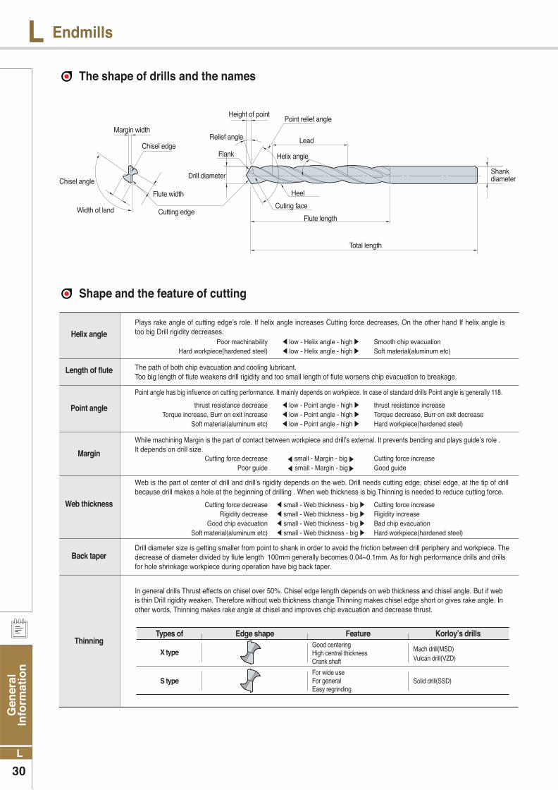
Gen
eral
In
form
atio
n
30
L
L Endmills
The shape of drills and the names
Shape and the feature of cutting
Helix angle
Length of flute
Point angle
Margin
Web thickness
Back taper
Thinning
Plays rake angle of cutting edge’s role. If helix angle increases Cutting force decreases. On the other hand If helix angle is too big Drill rigidity decreases. Poor machinability low - Helix angle - high Smooth chip evacuation Hard workpiece(hardened steel) low - Helix angle - high Soft material(aluminum etc)
Point angle has big influence on cutting performance. It mainly depends on workpiece. In case of standard drills Point angle is generally 118.
thrust resistance decrease low - Point angle - high thrust resistance increase Torque increase, Burr on exit increase low - Point angle - high Torque decrease, Burr on exit decrease Soft material(aluminum etc) low - Point angle - high Hard workpiece(hardened steel)
While machining Margin is the part of contact between workpiece and drill’s external. It prevents bending and plays guide’s role . It depends on drill size. Cutting force decrease small - Margin - big Cutting force increase Poor guide small - Margin - big Good guide
Web is the part of center of drill and drill’s rigidity depends on the web. Drill needs cutting edge, chisel edge, at the tip of drill because drill makes a hole at the beginning of drilling . When web thickness is big Thinning is needed to reduce cutting force.
Cutting force decrease small - Web thickness - big Cutting force increase Rigidity decrease small - Web thickness - big Rigidity increase Good chip evacuation small - Web thickness - big Bad chip evacuation Soft material(aluminum etc) small - Web thickness - big Hard workpiece(hardened steel)
The path of both chip evacuation and cooling lubricant. Too big length of flute weakens drill rigidity and too small length of flute worsens chip evacuation to breakage.
Drill diameter size is getting smaller from point to shank in order to avoid the friction between drill periphery and workpiece. The decrease of diameter divided by flute length 100mm generally becomes 0.04~0.1mm. As for high performance drills and drills for hole shrinkage workpiece during operation have big back taper.
In general drills Thrust effects on chisel over 50%. Chisel edge length depends on web thickness and chisel angle. But if web is thin Drill rigidity weaken. Therefore without web thickness change Thinning makes chisel edge short or gives rake angle. In other words, Thinning makes rake angle at chisel and improves chip evacuation and decrease thrust.
Types of
X type
S type
Good centering High central thicknessCrank shaft
For wide useFor general Easy regrinding
Mach drill(MSD)Vulcan drill(VZD)
Solid drill(SSD)
FeatureEdge shape Korloy’s drills
Margin width
Chisel edge
Flute width
Drill diameterChisel angle
Width of land Cutting edge
Heel
Shank diameter
Point relief angle
Helix angle
Height of point
Cuting face
Flute length
Total length
Relief angle
Flank
Lead

Gen
eral In
form
ation
31
L
LEndmills
Major cutting formulas
• vc : Cutting speed (m/min) • D : Drill diameter (mm) • n : Revolution per minute (min-1)• π : Circular constant (3.14)
vc = π·D·n (m/min) 1000
• fn : Feed per revolution (mm/rev) • vf : Feed per minute (mm/min) • n : Revolution per minute (min-1)
fn = vf (mm/rev) n
• Md : Cutting torque (kg·cm)• T : Cutting thrust (kg)• D : Drill diameter (mm)
• fn : Feed per revolution(mm/rev) • K : Material coefficient
δ=tan-1 πD L
Md = KD²×(0.0631+1.686×fn)(kg·cm)
T = 57.95KDfn0.85(kg)
Cutting speed Feed Helix angle Machining time
• δ : Helix angle • D : Drill diameter (mm) • L : Lead (mm)• π : Circular constant (3.14)
• tc : Machining time (min) • n : Revolution per minute (min-1) • Id : Drilling time (mm)• fn : Feed (mm/rev)
tc = Id (min) n·fn
Workpiece material(SAE/AISI) Tensile strength(kgf) Hardness(HB) Material coefficient K
Cast iron (Gray)
Cast iron
Cast iron (Ductile)
1020(carbon steel C 0.2%)
1112(C 0.12, S 0.2%)
1335(Mn 1.75%)
3115 (Ni 1.25, Cr 0.6, Mn 0.5)
3120 (Ni 1.25, Cr 0.6, Mn 0.7)
3140
4115 (Cr 0.5, Mo 0.11, Mn 0.8)
4130 (Cr 0.95, Mo 0.2, Mn 0.5)
4140 (Cr 0.95, Mo 0.2, Mn 0.85)
4615 (Ni 1.8, Mo 0.25, Mn 0.5)
4820 (Ni 3.5, Mo 0.25, Mn 0.6)
5150 (Cr 0.8, Mn 0.8)
6115 (Cr 0.6, Mn 0.6, V 0.12)
6120 (Cr 0.8, Mn 0.8, V 0.1)
Nickel Chrome steel
General steel
Cast iron
Chrome molybdenum steel
Nickel molybdenum steel
Chrome steel
Chrome vanadium steel
Workpiece K1 m K2 n
Md= K1·d2 · fnm
T= K2·d · fnn
21
28
35
55
62
63
53
69
88
63
77
94
75
140
95
58
80
5.9
3.5
2.5
1.5
1.4
2.0
0.3
1.00
1.00
0.94
0.90
0.88
0.94
0.57
125.0
55.0
44.4
33.3
27.0
21.6
6.4
0.88
0.88
0.87
0.78
0.74
0.75
0.55
Soft steel
Rolled steel
7-3 brass
Aluminum
Zinc
Gun metal
Galvanized Iron
177
198
224
160
183
197
163
174
241
167
229
269
212
390
277
174
255
1.00
1.39
1.88
2.22
1.42
1.45
1.56
2.02
2.32
1.62
2.10
2.41
2.12
3.44
2.46
2.08
2.22
Cutting torque and thrust(calculation formulas)
• Md : Cutting torque ( · ) • fn : Feed (mm/rev) • d : Drill diameter (mm) • T : Thrust ( ) • K1, K2, m, n : Experimental Data Characteristic value
Cutting torque and thrust (empirical formula)
( )

Gen
eral
In
form
atio
n
32
L
L Endmills
Tool failures and solutions
CausesTrouble
Solutions
Cutting condition
Cla
mp
ing
w
ork
pie
ce
Gu
ide
bu
sh
Mac
hin
e vi
bra
tio
n
Mac
hin
e ri
gid
ity
Har
dn
ess
Tou
gh
nes
s
Flu
te w
idth
ra
te
Ho
nin
g
Th
inn
ing
Tool shape Grade etc
: Increase : Decrease : use : Correct use
• Too sharp cutting edge (too big relief angle) (thinning edge is too sharp)
• Excessive cutting speed
• Built-up edge
• Vibration and chattering
• Excessive cutting speed (Abnormal wear at margin)
• Insufficient cutting speed (Abnormal wear at center)
• Long chip
• Over lap
• Chip burning
• Tool clamping precision
• Excessive feed, sharp point angle
• Excessive cutting speed (Considered tool grade)
• Poor surface finish
• Insufficient machine rigidity
• Improper cutting condition
• Crooked hole
• Chip clogging
Chipping
Wear
Chip
Hole precision Burr,
Poor surface finish
Breakage
on
contactFracture
Breakage
at hole
bottom
Cut
ting
spee
d
Ste
p f
eed
Init
ial f
eed
Co
ola
nt
Rel
ief
ang
le
Po
int
ang
le
Th
inn
ing
an
gle
Fee
d

Gen
eral In
form
ation
33
L
LEndmills
Hole size for threading
Metric coarse screw threads Metric coarse screw threads
Specification Hole diameter Specification Hole diameter
M1
M1.1
M1.2
M1.4
M1.6
M1.7
M1.8
M2
M2.2
M2.3
M2.5
M2.6
M3
M3
M3.5
M4
M4
M4.5
M5
M5
M5.5
M6
M7
M8
M9
M10
M11
M12
M14
M16
M18
M20
M22
M24
M27
M30
M33
M36
M39
M42
M45
M48
X
X
X
X
X
X
X
X
X
X
X
X
X
X
X
X
X
X
X
X
X
X
X
X
X
X
X
X
X
X
X
X
X
X
X
X
X
X
X
X
X
X
0.25
0.25
0.25
0.3
0.35
0.35
0.35
0.4
0.45
0.4
0.45
0.45
0.6
0.5
0.6
0.75
0.7
0.75
0.9
0.8
0.9
1
1
1.25
1.25
1.5
1.5
1.75
2
2
2.5
2.5
2.5
3
3
3.5
3.5
4
4
4.5
4.5
5
0.75
0.85
0.95
1.1
1.25
1.35
1.45
1.6
1.75
1.9
2.1
2.2
2.4
2.5
2.9
3.25
3.3
3.8
4.1
4.2
4.6
5
6
6.8
7.8
8.5
9.5
10.3
12
14
15.5
17.5
19.5
21
24
26.5
29.5
32
35
37.5
40.5
43
M2.5
M3
M3.5
M4
M4.5
M5
M5.5
M6
M7
M8
M8
M9
M9
M10
M10
M10
M11
M11
M12
M12
M12
M14
M14
M15
M15
M16
M16
M17
M17
M18
M18
M18
M20
M20
M20
M22
M22
M22
M24
M24
M24
M25
M25
M25
M26
M27
X
X
X
X
X
X
X
X
X
X
X
X
X
X
X
X
X
X
X
X
X
X
X
X
X
X
X
X
X
X
X
X
X
X
X
X
X
X
X
X
X
X
X
X
X
X
0.35
0.35
0.35
0.5
0.5
0.5
0.5
0.75
0.75
1
0.75
1
0.75
1.25
1
0.75
1
0.75
1.5
1.25
1
1.5
1
1.5
1
1.5
1
1.5
1
2
1.5
1
2
1.5
1
2
1.5
1
2
1.5
1
2
1.5
1
1.5
2
2.2
2.7
3.2
3.5
4
4.5
5
5.3
6.3
7
7.3
8
8.3
8.8
9
9.3
10
10.3
10.5
10.8
11
12.5
13
13.5
14
14.5
15
15.5
16
16
16.5
17
18
18.5
19
20
20.5
21
22
22.5
23
23
23.5
24
24.5
25

Gen
eral
In
form
atio
n
34
L
L Drilling
Cautions
Notice
Regrinding procedures
• Collect chuck is favorable Because it has strong grip power (General drill-chuck and Keyless chuck don’t have enough grip power.)
• Collect chuck • General drill-chuck
• When mounting drill Periphery chattering should be within 0.02 .• Flute should not be clamped.
• Supply enough coolant around hole entrance.• Standard cutting oil pressure : 3~5kg/ , Flux : 2~5l/min.
• At high performance drilling High thrust, torque and horizontal cutting force work at the same time so that workpiece should be clamped strongly to prevent chattering.
• Supply much coolant at hole entrance
• Strong clamping is needed because bending causes chipping
Selection of drill chuck Coolant supply
Mounting drill How to clamp workpiece
• Uniformed and strong clamping is needed (Right and left, up and down)
• Periphery chattering within 0.02
• No clamping flute
Regrinding mathod (Mach Drill)
1) For better drill’s life, small damage and wear are favorable to be regrinding.2) Damage and wear size should be within 1.5 for regrinding.3) If drill has crack, regrinding is impossible.4) Ordering for regrinding is acceptable or purchase regrinding machine
1) Preparation - Determination of regrinding
areas Check the cutting edge for damage and wear If large fracture is found, remove it by rough grinding.
Feed mark
Max.0.02mm
2) Grinding operation - Drills setting Drill is clamped to collet chuck Chattering is kept within 0.02mm.
Chipping
Point
Thining
N/L, Horning

Gen
eral In
form
ation
35
L
LDrilling
3) Grinding operation-Grinding point - Check damage and wear at the point and remove it completely.- The difference of the lip height is kept within 0.02mm.
Point angle(a) : 140°
Point relief angle(b)t : 8°~ 15°
The difference of the
lip height Max. 0.02mm
4) Grinding operation-Thinning grinding - Considering N/L width Cutting edge length from the center of drill
axis should be 0.03~0.08mm for balancing. - Set the wheel to tilt drill axis by 34°~ 40°.
Thinning angle(a)° : 155°~ 160°/ Thining open angle(b) : 100°~ 105° Thinning relief angle(c) : 34°~ 40°
Counter boring and size of bolt hole for hexagonal socket bolt
5) Grinding - N/L grinding and honing - Using diamond chisel Grinds the width flat along point cutting edge. - After negaland operation Finishes with brush or handstone.
N/L width(a) : 0.05mm~0.16mm / N/L angle(b) : 24°~26°
• N/L
TIP· Making point - Without center drill, the point width should be below 0.10mm.
· Recommended grinding condition - Diamond wheel : 240~400 mesh - Diamond chisel : 400~600 mesh - Diamond hand stone : 800~1500 mesh
ISO (d)
Ød1
Ød′ØDØD′HH′H″
33.45.553
2.73.3
44.5784
3.64.4
55.58.59.55
4.65.4
66.510116
5.56.5
88.513148
7.48.6
101116
17.5109.2
10.8
1214182012
11.013.0
1416212314
12.815.2
1618242616
14.517.5
1820272918
16.519.5
2022303220
18.521.5
2224333522
20.523.5
2426363924
22.525.5
27304043272529
30334548302832
M3 M4 M5 M6 M8 M10 M12 M14 M16 M18 M20 M22 M24 M27 M30
Hexagonal socket bolt(Clamping screw) size

Gen
eral
In
form
atio
n
36
L
L General Information Ⅱ
The comparison of chip breakers
P M K
Application
FinishingVL XP FA LU PF UF - PF FV FF1
VF GP - FP, FC, SI UF - PF PF, PF2 SV F1
Medium machining
- XQ FG - PM LF 14 - - MF2
HMP HQ,CK PC SU, SC UM - SM PF4,PF5 MV F2
Roughing C25 MT MU PR, UR MF - PM5 M5
High feed- - - LUW WF FW WF PF SW F1
- - WT - WM MW - PM MW F2
M,S Stainless steel For HRSAVP1 CF,GF,GQ FG FC KF LF PF PM FJ, LM F1
- MQ SA - KM MF SM PM5 AM, MM MF2
K Cast ironHMP GK PC MU UM LF 17 - M3
C25 HQ MT C/B KR MF,UF 19 C/B C/B M5
N Aluminium AK, AR AH FL AW, AG AL HP AS, AF PM2 F AL
High precision bar turning(tolerance class G&E) KF, KM FSF,USF GF, FF FY, FX,FZ UM -GH LF,RF,XL - F, SR, SS, SM UX
APPLICATION KORLOY KYOCERA TAEGUTEC SUMITOMO SANDVIK KENNAMETAL ISCAR WLATER MITSUBISHI SECO
P
Steel
Ultra-Finishing- DP (G) - - - FF(G) - - PK(G) -
VL GP, PP FA FA, FL QF UF SF NF3 FH,FS FF1
FinishingVF HQ FG LU, SU PF FN NF NF4 SH, C FF2
VB - SF SE 61 - F3M PF5 LP -
Medium to finishing
VQ, HC CQ MC SX - LF, CT TF NS6 SA, C() MF2, MF3
VC PQ FC - - - - MP3 MV MF5
Medium machining
GM, HM, VM HK, CS GS HS, PS MP, MT GU, UX QM, SM MP, MN GN NM4, NP5 MA,MH M3, M5
- - PC GE PM - M3M NM5,NM6 MP -
RoughingB25 - - - - - M5
HR, GR PT,GT, HT, PH RT MU,ME, MX PR RN NR, R3M NM9, PP5 GH, RP MR5,MR6, MR7
Heavy duty machining
GH PX RH, RX HG, MP PR RH NM NR4, NRF HZ R4,R5
VH HX HZ HP QR RM HR NR8 HV, HX, HAX R6, R7, R8
VT - HT, HY HU,HW,HF HR MM - - HBS,HCS, HDS,HXD
RR6, PR9, R56,R57,R68
Low carbon steel
Soft steelVL XF, XP, XP-T SF FL LC - - - FY -
- XQ, XS - - - - - - SY -
High feedHigh feed
cutting
VW WP WS LUW,SEW WF,WL FW WF NF SW FF2, MF2
LW WQ WT GUW WM,WMX MW WG NM MW MF5, M3
- - - - WR RW - - - R4,R7
Application Shaft (long bar)SH CJ, ST FS, VF, FX HM K - - - ES UX
KNUX- KNMX- KNUX- - KNUX-71 - - - KNMX-19 -
M Stainless steel
HA, VP2 MQ, GU EA SU MF FP F3P NF4 LM MF1
GS, HS HU, TK, MU MP, EM EX, GU MM MP M3M NM4 MA, GM, MM MF3
VM MS ET MU, HM MR RP R3M NR4 RM M5
K Cast iron
VM C MT UZ KF FN TF NM, MK5 LK M4
GR, VK ZS RT KT UX, GZ KM RP GN NM5, RK5 MA, MK M5
-MA -MA, GC -MA -MA KR UN -MA -MA, MK5 GH, -MA, RK MR7
S HRSA
VP1 MQ EA EF - FS, LF PF NF4 FJ(G), LS M1
VP2 TK ML UP, EG 23.SR MS PP - MJ MF1
VP3 MS,MU EM EX Xcel-SM MP VL NM4 MS, MS MF4
VM - ET MU - RP - NR4GJ, RS
MR4
N Aluminium HA AH ML UP (GX), AG 23 MS PP - MJ MF1
NE
GA
TIV
EP
OS
ITIV
E
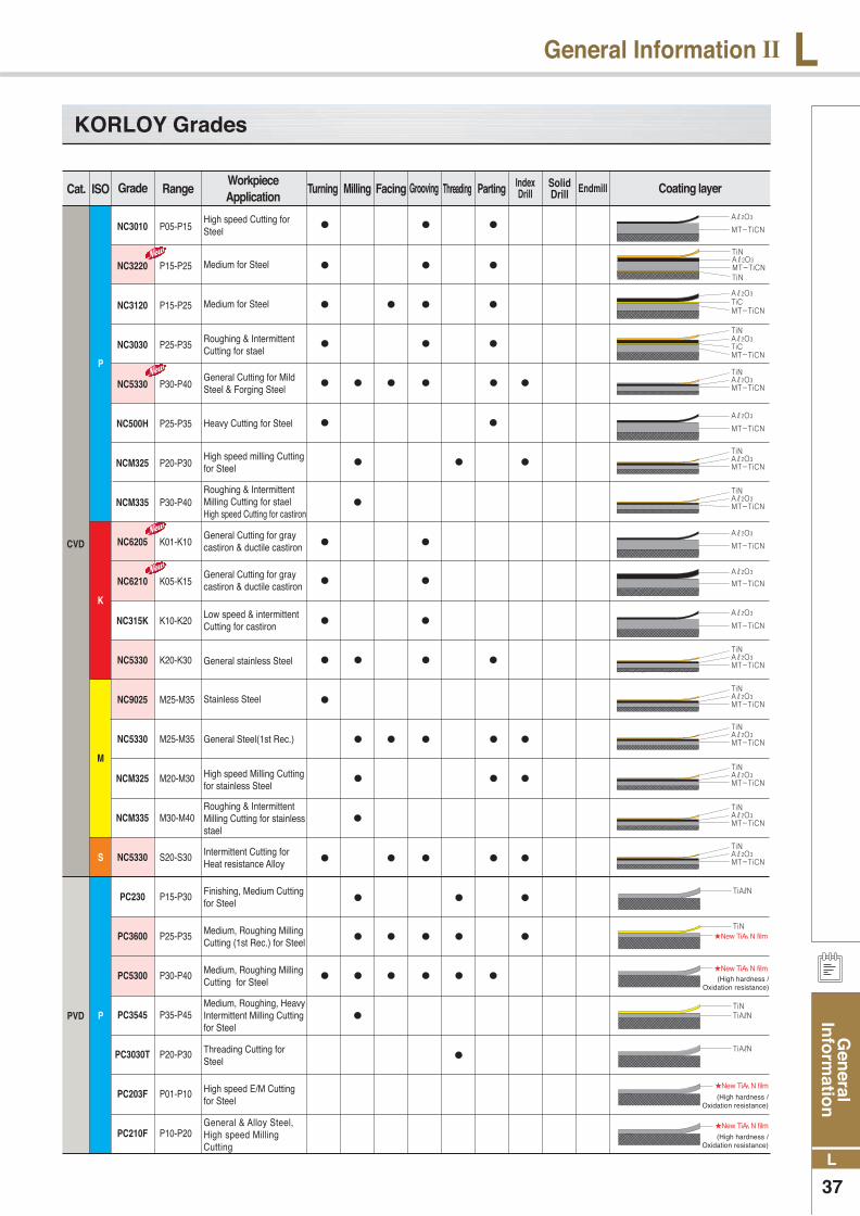
Gen
eral In
form
ation
37
L
LGeneral Information Ⅱ
KORLOY Grades
Cat. ISO Coating layerTurning Milling Facing Grooving Threading Parting SolidDrill EndmillIndex
DrillGrade RangeWorkpiece Application
P
P
K
M
S
PVD
CVD
NC3010
NC3220
NC3120
NC3030
NC5330
NC500H
NCM325
NCM335
NC6205
NC6210
NC315K
NC5330
NC9025
NC5330
NCM325
NCM335
NC5330
PC230
PC3600
PC5300
PC3545
PC3030T
PC203F
PC210F
P05-P15
P15-P25
P15-P25
P25-P35
P30-P40
P25-P35
P20-P30
P30-P40
K01-K10
K05-K15
K10-K20
K20-K30
M25-M35
M25-M35
M20-M30
M30-M40
S20-S30
P15-P30
P25-P35
P30-P40
P35-P45
P20-P30
P01-P10
P10-P20
High speed Cutting for Steel
Medium for Steel
Medium for Steel
Roughing & Intermittent Cutting for stael
General Cutting for Mild Steel & Forging Steel
Heavy Cutting for Steel
High speed milling Cutting for Steel
General Cutting for gray castiron & ductile castiron
Low speed & intermittent Cutting for castiron
General stainless Steel
Stainless Steel
General Steel(1st Rec.)
Intermittent Cutting for Heat resistance Alloy
Finishing, Medium Cutting for Steel
Medium, Roughing Milling Cutting (1st Rec.) for Steel
Medium, Roughing Milling Cutting for Steel
Medium, Roughing, Heavy Intermittent Milling Cutting for Steel
Threading Cutting for Steel
High speed E/M Cutting for Steel
Roughing & Intermittent Milling Cutting for stael High speed Cutting for castiron
General Cutting for gray castiron & ductile castiron
High speed Milling Cutting for stainless Steel
Roughing & Intermittent Milling Cutting for stainless stael
General & Alloy Steel, High speed Milling Cutting
New TiAℓN film
New TiAℓN film
(High hardness /Oxidation resistance)
New TiAℓN film
(High hardness /Oxidation resistance)
New TiAℓN film
(High hardness /Oxidation resistance)

Gen
eral
In
form
atio
n
38
L
L General Information Ⅱ
KORLOY Grades
Cat. ISO Coating layerGrade RangeWorkpiece Application
P
K
M
S
PVD
PC3600
PC220
PC205F
PC8110
PC6510
PC5300
PC203F
PC220
PC205F
PC215K
PC8110
PC5300
PC9030
PC9530
PC3545
PC3030T
PC210
PC205F
PC8110
PC5300
PC3545
PC210
PC205F
P15-P35
P15-P35
P15-P30
K01-K15
K01-K15
K15-K25
K01-K10
K15-K35
K10-K20
K15-K30
M01-M10
M20-M35
M20-M35
M20-M35
M30-M50
M20-M30
M15-M30
M15-M30
S01-S20
S15-S25
S30-S50
S15-S30
S15-S25
●
●
●
●
●
●
●
●
●
● ● ●
● ● ●
● ● ● ● ● ● ●
● ● ● ● ● ● ●
● ● ● ●
● ● ●
● ● ● ● ● ● ● ●
● ●
●
●
●
●
● ● ● ●
● ● ●
Turning Milling Facing Grooving Threading Parting SolidDrill EndmillIndex
Drill
Milling, Turning Cutting Finishing for cast iron
General milling for steel
General E/M Cutting for Heat resistant Alloy Steel
Drill Cutting(General)/under φ20 for Solid Drill
Medium to Finishing Turning Cutting for Heat resistant Alloy Steel
Roughing/ Heavy Intermittent Milling Cutting for Heat resistant Alloy Steel
Medium to Roughing Turning/Milling Cutting for Heat resistant Alloy Steel
Finishing to Medium Cutting for stainless Steel
Medium, Roughing Turning/Milling Cutting for stainless Steel
Medium, Roughing & Intermittent Turning Cutting for stainless Steel
Medium, Roughing & Intermittent Milling Cutting for stainless Steel
Roughing/ Heavy Inermittent Milling Cutting stainless Steel
Threading Cutting for stainless Steel
General E/M Cutting for stainless Steel
Drill Cutting(General)/under φ20 for Solid Drill
High speed Milling Cutting for castiron
Medium & Roughing Turning/Milling Cutting for castiron
High speed l E/M Cutting for castiron
General E/M Cutting for castiron
Drill Cutting(General)/under φ20 for Solid Drill
Medium & Roughing Milling Cutting for castiron
General E/M Cutting for Steel
Drill Cutting (general)/under Ø20 for Solid Drill
New TiAℓN film
(High hardness /Oxidation resistance)
NewTiAℓN film
(High hardness /Oxidation resistance)
New TiAℓN film(High hardness /
Oxidation resistance)
New TiAℓN film(High hardness /
Oxidation resistance)
New TiAℓN film
(High hardness /Oxidation resistance)
New TiAℓN film(High hardness /
Oxidation resistance)
New TiAℓN film(High hardness /
Oxidation resistance)
New TiAℓN film(High hardness /
Oxidation resistance)
New TiAℓN film(High hardness /
Oxidation resistance)
New TiAℓN film(High hardness /
Oxidation resistance)
New TiAℓN film(High hardness /
Oxidation resistance)
New TiAℓN film(High hardness /
Oxidation resistance)

Gen
eral In
form
ation
39
L
LGeneral Information Ⅱ
KORLOY Grades
DLC
DLC
DLC
Dia Coating
P
P
K
K
K
N
H
N
N
N
Un
coat
edC
erm
etcB
NP
CD
DL
CD
iam
on
d C
oat
ing
A30
H01
H05
G10
H01
CC105
CC115
CC125
CN1000
CN20
CN2000
CN30
CN1000
KB410
KB420
DBN210
KB425
KB320
DBN350
KB350
KB370
DP90
DP150
DP200
PD1000
PD2000
PD3000
ND1000
ND2000
ND3000
P25-P35
K05-K15
K05-K15
K15-K25
N05-K15
P01-P10
P10-P20
P15-P25
P05-P15
P15-P25
P10-P20
P20-P30
K05-K10
H01-H10
H05-H15
H10-H20
H15-H25
H15-H25
H25-H35
K01-K10
K05-K15
N01-N10
N05-N15
N10-N20
N01-N20
N01-N20
N01-N20
N01-N20
N01-N20
N01-N20
Finishing for cast iron
Cat. ISO Coating layerTurning Milling Facing Grooving Threading Parting SolidDrill EndmillIndex
DrillGrade RangeWorkpiece Application
General Cutting for Steel
Finishing Cutting for castiron, Nonferrous Metal(Al. etc)
Finishing Cutting for castiron, Nonferrous Metal(Al. etc)
Medium Cutting for castiron
High speed light Cutting for Steel (optimal precise boring)
Medium, High speed light Cutting for Steel
Medium, Roughing Milling Cutting for Steel
General Turning/Milling Cutting for Steel
Roughing Milling Cutting for Steel
Medium, Roughing Turning/Milling Cutting for Steel
High Efficiency Cutting for Heat treatment steel
High speed continuous/light intermittent Cutting for Heat treatment steel
Intermittent Cutting for Heat treatment steel(Heavy intermittent)
Cemented carbide, Ceramic roughing, High Si-Al alloy, Rock, Stone
High speed continuous Cutting for Heat treatment steel
High speed intermittent Cutting for Heat treatment steel
High Si-Al alloy, copper Alloy, Rubber, Wood, Carbon
Plastic, Wood, Al precise finishing Cutting
Nonferrous(Al. etc) Turing cutting
Nonferrous(Al. etc) Milling cutting
Nonferrous(Al. etc) E/M cutting
Nonferrous(graphite, Al, Bronze) Turning cutting
Nonferrous(graphite, Al, Bronze) Milling cutting
Nonferrous(graphite, Al, Bronze) E/M cutting
Continuous, intermittent Cutting for Heat treatment steel
High speed Cutting for Castiron
High Hardness cutting for castiron
High speed cutting for castiron
Highspeed Cutting for Steel(Sintered Metal Cutting)

Gen
eral
In
form
atio
n
40
L
L General Information Ⅱ
The comparison of grade for turning
PVD Coated
WC
CVD Coated
: PVD Coating cermet : New Grade
CERMET
ST50EST10P
ST20EMA2ST30EA30ST30NST40EU10EU2
A40H2H01H05H10G10E
ST10PST20E
A30
ST40EU10EU2A30A40
H1
G10E
PW30
KW10H
IC50MIC54
IC4
IC20IC28
S1P
SM30
S30TS6
H13AH10F
H1P
H10F
TTXTTMTTR
AT10AT15TTR
THM
THR
K45KMK420
K2885K2S
K68
K8735
TX10STX20
TX30
TX40TU10TU20
TU40
TH03TH10KS20
STi10TSTi20T
UTi20T
UTi20T
HTi10THTi20T
SRN5WS20B
EX35EX40EX45WAM10B
EX35
WH05W10WH20
S1F
VC6VC5VC56
VC27VC28
VC3VC2VC1
P10P20
P30P40
M10M20
M40
K10K20K20MK30
P
M
K
P
M
K
P
M
K
S
ISO
ISO
NC3010NC3220★
NC3120NC3030NC5330★
NC500H
NC9020
NC9025
NC6205★
NC6210★
NC315KNC5330★
AC810PAC820P
AC830P
AC610M
AC630M
AC410KAC420K
CA5505CA5515CA5525
CA5535
CA6515
CA6525
CA4505CA4515CA4120
IC8150IC8250
IC8350
IC8250
IC8350
IC5005IC5010
GC4205GC4215GC4225
GC4235
GC2015
GC2025
GC3205GC3210GC3215
TP0500TP1500TP2500
TP3500
TM2000
TM4000
TK1001TK2001
KCP05KCP10KCP25
KU30KCP40
KCM15KCM25KCM35
KCK05KCK15KCK20
T9105T9115T9125
T9135
T6020
T6030
T5105T5115T5125
UE6105UE6110UE6020
UE6035
US7020
US735
UC5105UC5115
HG8010HG8025
GM8035
GM25
GX30
HG3505HG3515
VP5515VP5525
VP5535
VP8515
VP8525
VP1505VP1510VP5515
WPP01WPP05WPP10WPP20
WPP30
WAM10
WAM20
WAK10WAK20
TT8115TT8125
TT8135
TT7100
TT9215TT9225TT9235
TT1300TT7310
CP5
CP2CP5
JC110VJC215V
JC325V
JC450
TT9215TT9225TT9235
JC105VJC110VJC215V
P
M
K
ISO
CN1000
CC115★CN2000CN20
CN1000
T110AT2000Z★
T1500A★T3000Z★
T1500A★
T110AT1500A★
PV30★TN30
PV60★TN60TN6020TN90
IC20NIC520N
IC30NIC530N
CT5015
CT525GC1525★
CMC15M
TP1020
TP1030★
HT2KT125HT5KT175KT195M
NS520GT530★NC530NC540NC730
NX2525NX3035UP35N★AP25N★NX335
NX2525
NX2525
CH350CZ25★CH530CH550CH570
VC83 WTA43★WTA41★
PV3010★CT3000
CT3000
T3NT15N20
C30
N40
T15
LN10CX50CX75
CX90CX99
LN10CX75CX99LN10CX75
VP15TFVP20MF
VP05RTVP10RT
VP15TFVP20MF
VP05RTVP10RTVP15TF
PC230
PC5300★
PC3545
PC8110★
PC5300★
PC9030
PC5300★
PC8110★
PC5300★
AC510UEH510ZAC520UEH520ZAC530U★
EH510ZEH520Z
AC510UAC520U
PR1005PR915PR1115PR930PR1025PR630PR660
PR915PR930
PR1125PR630PR660
PR915PC660
GC1025
GC4125
GC1005GC1105★
GC1020GC1025GC4125
GC1105GC1025
CP200
CP250
CP500
CP200CP250
CP500
CP200CP250CP500TS2000★
CP500TS2500★
KU10TKU25T
KC5010KC5510★
KC5025KC5525
KC5010KC5025
AH710
GH730
AH330AH740AH120GH330
AH330GH330AH120GH730AH140
AH110GH110AH120
AH110AH120
IP2000
IP3000
IP50S★
IP100S★
CY110H
VC907VC927
VC905
VC929VC927VC902VC901VC905
VC929VC903VC927VC902VC901VC907
WTA43
WTA41 TT5030
TT5030
TT5030
TT5030
ZM3QM3VM1TAS
JC5003
JC5015
JC5003
JC5015
IC507IC808★
IC830★
IC908IC3028
IC330★
IC808★
IC907
IC3028IC830★
IC330★
IC5100★
IC810★
IC220IC908IC228IC808★
IC907IC3028
KORLOY SUMITOMO KYOCERA ISCAR SANDVIK SECO KENNAMETAL TOSHIBA MITSUBISHI HITACHI VALENITE WALTER TAECUTEC NTK DIJET
KORLOY SUMITOMO KYOCERA ISCAR SANDVIK SECO KENNAMETAL TOSHIBA MITSUBISHI HITACHI VALENITE WALTER TAECUTEC NTK DIJET
KORLOY SUMITOMO KYOCERA ISCAR SANDVIK SECO KENNAMETAL TOSHIBA MITSUBISHI HITACHI VALENITE WALTER TAECUTEC NTK DIJET
KORLOY SUMITOMO KYOCERA ISCAR SANDVIK SECO KENNAMETAL TOSHIBA MITSUBISHI HITACHI VALENITE WALTER TAECUTEC NTK DIJET
Tu
rn
ing
Tu
rn
in
gT
ur
nin
gT
ur
nin
g

Gen
eral In
form
ation
41
L
LGeneral Information Ⅱ
The comparison of grade for milling
CVD Coated
CERMET
PVD Coated
: PVD Coating cermet : New Grade
P
M
K
ISO
CN2000CN20CN30
T250A
T250A
TN100M
TC60M IC30N
CT530
KT195MNS540NS740
NX2525
NX4545
NX2525
CH550CH570
CT3000
CT7000C50
KORLOY SUMITOMO KYOCERA ISCAR SANDVIK SECO KENNAMETAL TOSHIBA MITSUBISHI HITACHI VALENITE WALTER TAECUTEC NTK DIJET
Mil
lin
g
P
M
K
S
ISO
PC210F
PC3600PC3500
PC5300★
PC3545
PC5300★
PC9530
PC3545
PC8110★
PC6510
PC5300★
PC5300★
ACZ310
ACP200
ACZ330
ACP300ACZ350
ACP200
ACP300ACZ350
AC520U
PR730
PR830PR630
PR660
PR730
PR1025PR630PR660
PR510PR905
PC660
IC903IC908IC950
IC1008
IC928
IC903
IC900IC250IC928
IC328
DT7150IC900IC910IC950IC350IC328
GC1010
GC1025GC1030
GC1030
GC1125GC1025GC2030GC1030
GC1025
MP3000★
F25MF30M
F40MT60M
F25M
F30M
F40M
TS2500
KC522MKUC20M
KC525MKUC30M
KC935MKC7140KC720KC5510KC7020
KC522MKC725MKC735MKC7030
KC722
KC510MKC915M
KC520M
KC510M
GH330
AH120
AH120
AH140
AH120
AP20MGP20M
VP15TF
UP20M
VP30RT
VP10MFVP15TF
VP20RT
VP15TF
ATH80DPCA08MACS05EPCA12MPC20MJX1005TB6005JX1020CY9020
TB6045CY250PTH30E
PTH40HJX1020CY9020JX1015TB6020CY250
JX1045TB6045
JX1060TB6060
ACS05E
VC935
VC928VC902VC901
VC903VC928
VC902VC901
WQM35
WSP45
TT7070TT7080TT7030
TT8020
TT9030
TT9080
TT8020
TT6290
TT6030TT6060TT9030
JC5003
JC5015
JC5030JC5040
JC5003
JC5015
JC5030JC5040
JC5003
JC5015
QM3ZM3
QM3ZM3
KORLOY SUMITOMO KYOCERA ISCAR SANDVIK SECO KENNAMETAL TOSHIBA MITSUBISHI HITACHI VALENITE WALTER TAECUTEC NTK DIJET
NC5330★
NCM325
NCM335
NC5330★
MCM325NCM335
NC5330★
ACP100
ACK200
IC5400
IC5100
GC4220
GC4230
GC4240
GC2040GC3220
MP1500
MP2500T25MT350M
MP2500GC2040MK1500MK3000 KC992M
T3130
T3130
T1115T1015
FH7020F7030
F7030
MC5020
SM245
V01VN8
WQM15
WKP25WQM25WKP35WQM35
WQM25WTP35WAK15WKP25WKP35
TT7400
TT7800
TT6800
P
M
K
ISO KORLOY SUMITOMO KYOCERA ISCAR SANDVIK SECO KENNAMETAL TOSHIBA MITSUBISHI HITACHI VALENITE WALTER TAECUTEC NTK DIJET
Mil
lin
gM
illi
ng