Embed Size (px)
Citation preview
General technical information
1
Use ratings Power and motorization Neutral system Kerys configurations Protection and Normal/Emergency Switch Canopies and containers Exhaust Fuel How to install a generating set?
Use ratings
2
This document is intended to help you calculate the size of the generating set to suit the requirements of each application. The four types of ratings governed by standards (ISO8528-1) are as follows:
- emergency standby power (ESP) - limited running time power (LTP) - prime power (PRP) - continuous power (COP)
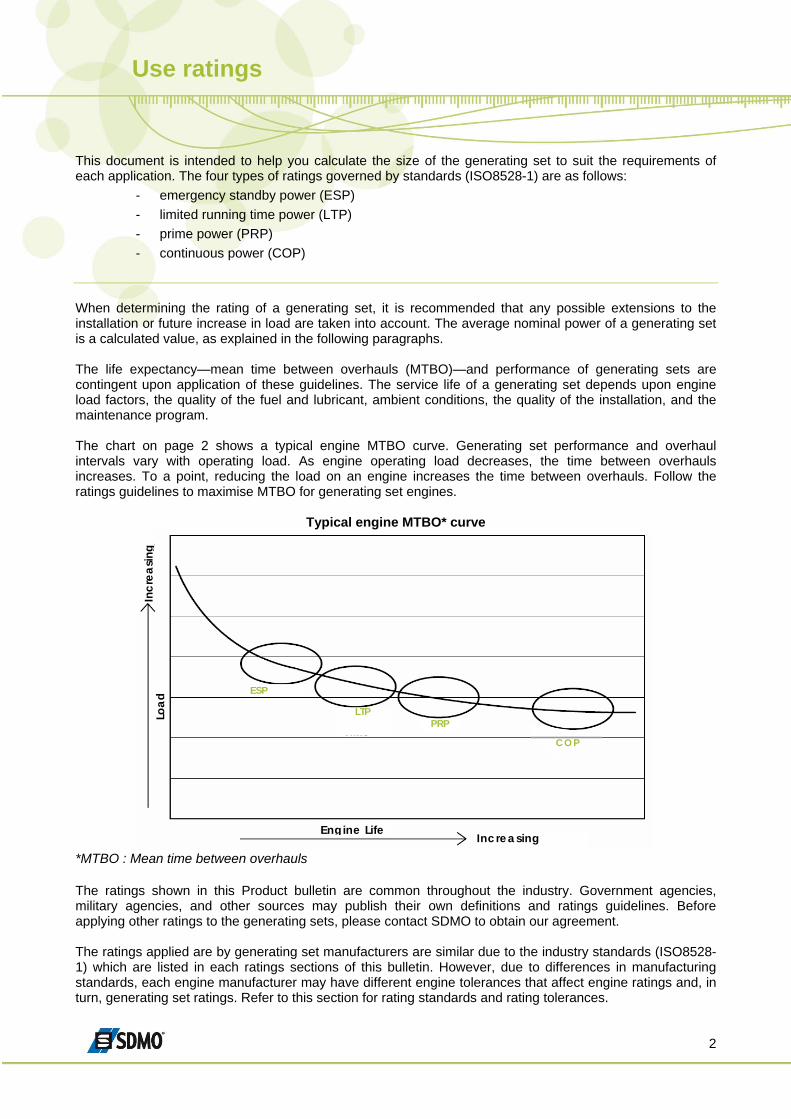
When determining the rating of a generating set, it is recommended that any possible extensions to the installation or future increase in load are taken into account. The average nominal power of a generating set is a calculated value, as explained in the following paragraphs. The life expectancy—mean time between overhauls (MTBO)—and performance of generating sets are contingent upon application of these guidelines. The service life of a generating set depends upon engine load factors, the quality of the fuel and lubricant, ambient conditions, the quality of the installation, and the maintenance program. The chart on page 2 shows a typical engine MTBO curve. Generating set performance and overhaul intervals vary with operating load. As engine operating load decreases, the time between overhauls increases. To a point, reducing the load on an engine increases the time between overhauls. Follow the ratings guidelines to maximise MTBO for generating set engines.
Typical engine MTBO* curve
ESP
LTP PRP
Increasing Engine Life
Incr
easin
g Lo
ad
COP
*MTBO : Mean time between overhauls The ratings shown in this Product bulletin are common throughout the industry. Government agencies, military agencies, and other sources may publish their own definitions and ratings guidelines. Before applying other ratings to the generating sets, please contact SDMO to obtain our agreement. The ratings applied are by generating set manufacturers are similar due to the industry standards (ISO8528-1) which are listed in each ratings sections of this bulletin. However, due to differences in manufacturing standards, each engine manufacturer may have different engine tolerances that affect engine ratings and, in turn, generating set ratings. Refer to this section for rating standards and rating tolerances.
Use ratings
3
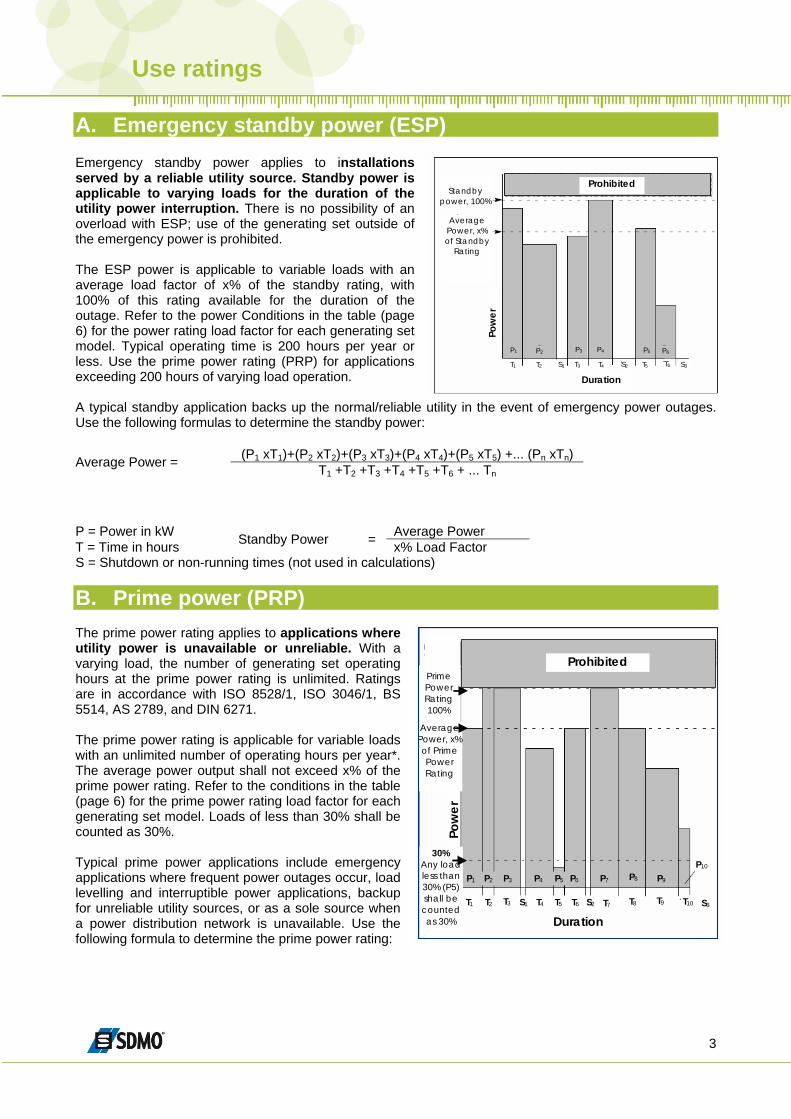
A. Emergency standby power (ESP) Emergency standby power applies to installations served by a reliable utility source. Standby power is applicable to varying loads for the duration of the utility power interruption. There is no possibility of an overload with ESP; use of the generating set outside of the emergency power is prohibited.
Duration
Standby
power, 100%
Average Power, x% of Standby
Rating
Pow
er
P1 P2 P3 P4 P5 P6
T1 T2 T3 T4 T5 T6 S1 S2 S3
Prohibited
The ESP power is applicable to variable loads with an average load factor of x% of the standby rating, with 100% of this rating available for the duration of the outage. Refer to the power Conditions in the table (page 6) for the power rating load factor for each generating set model. Typical operating time is 200 hours per year or less. Use the prime power rating (PRP) for applications exceeding 200 hours of varying load operation. A typical standby application backs up the normal/reliable utility in the event of emergency power outages. Use the following formulas to determine the standby power:
(P1 xT1)+(P2 xT2)+(P3 xT3)+(P4 xT4)+(P5 xT5) +... (Pn xTn) Average Power = T1 +T2 +T3 +T4 +T5 +T6 + ... Tn P = Power in kW Average Power T = Time in hours Standby Power = x% Load Factor S = Shutdown or non-running times (not used in calculations)
B. Prime power (PRP)
Time
Prohibited
Pow
er
P1 P2 P3 P4 P5 P6 P7 P8 P9 P10
T1 T2 T3 T4 T5 T6 T7 T8 T9 T10 S1 S2 S3
Prime Power Rating 100%
Average Power, x% of Prime Power Rating
30% Any load less than 30% (P5) shall be counted as 30% Duration
Pow
er
Prohibited
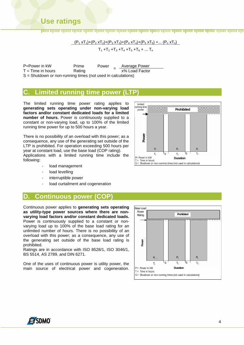
The prime power rating applies to applications where utility power is unavailable or unreliable. With a varying load, the number of generating set operating hours at the prime power rating is unlimited. Ratings are in accordance with ISO 8528/1, ISO 3046/1, BS 5514, AS 2789, and DIN 6271. The prime power rating is applicable for variable loads with an unlimited number of operating hours per year*. The average power output shall not exceed x% of the prime power rating. Refer to the conditions in the table (page 6) for the prime power rating load factor for each generating set model. Loads of less than 30% shall be counted as 30%. Typical prime power applications include emergency applications where frequent power outages occur, load levelling and interruptible power applications, backup for unreliable utility sources, or as a sole source when a power distribution network is unavailable. Use the following formula to determine the prime power rating:
Use ratings
4
(P1 xT1)+(P2 xT2)+(P3 xT3)+(P4 xT4)+(P5 xT5) +... (Pn xTn)
T1 +T2 +T3 +T4 +T5 +T6 + ... Tn
P=Power in kW Average Power T = Time in hours
Prime Power Rating = x% Load Factor
S = Shutdown or non-running times (not used in calculations) C. Limited running time power (LTP) The limited running time power rating applies to generating sets operating under non-varying load factors and/or constant dedicated loads for a limited number of hours. Power is continuously supplied to a constant or non-varying load, up to 100% of the limited running time power for up to 500 hours a year.
LimitedRunning
Time Rating
P1 P2 P3
T1 T2 T3 S S
Prohibited Limited
running timepower
Powe
r
P= Power in kWT = Time in hours S = Shutdown or non-running times (not used in calculations)
Duration
There is no possibility of an overload with this power; as a consequence, any use of the generating set outside of the LTP is prohibited. For operation exceeding 500 hours per year at constant load, use the base load (COP rating). Applications with a limited running time include the following:
- load management - load levelling - interruptible power - load curtailment and cogeneration
D. Continuous power (COP)
Base Load Power Rating
Powe
r
P1 P2 P3
T3 S T2 T1 S
P = Power in kW T = Time in hours S = Shutdown or non-running times (not used in calculations)
Duration
Prohibited
Continuous power applies to generating sets operating as utility-type power sources where there are non-varying load factors and/or constant dedicated loads. Power is continuously supplied to a constant or non-varying load up to 100% of the base load rating for an unlimited number of hours. There is no possibility of an overload with this power; as a consequence, any use of the generating set outside of the base load rating is prohibited. Ratings are in accordance with ISO 8528/1, ISO 3046/1, BS 5514, AS 2789, and DIN 6271. One of the uses of continuous power is utility power, the main source of electrical power and cogeneration.
Use ratings
5
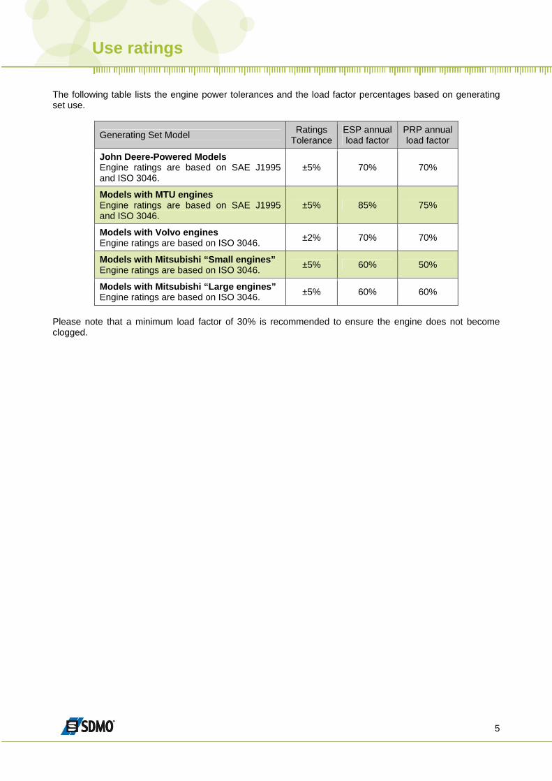
The following table lists the engine power tolerances and the load factor percentages based on generating set use.
Generating Set Model Ratings Tolerance
ESP annual load factor
PRP annual load factor
John Deere-Powered Models Engine ratings are based on SAE J1995 and ISO 3046.
±5% 70% 70%
Models with MTU engines Engine ratings are based on SAE J1995 and ISO 3046.
±5% 85% 75%
Models with Volvo engines Engine ratings are based on ISO 3046. ±2% 70% 70%
Models with Mitsubishi “Small engines” Engine ratings are based on ISO 3046. ±5% 60% 50%
Models with Mitsubishi “Large engines” Engine ratings are based on ISO 3046. ±5% 60% 60%
Please note that a minimum load factor of 30% is recommended to ensure the engine does not become clogged.
Power and motorization
6
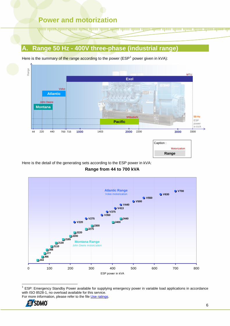
A. Range 50 Hz - 400V three-phase (industrial range) Here is the summary of the range according to the power (ESP1 power given in kVA):
715
ESP powerin kVA
44 220 440 700 1403 2200 3300
Exel
Atlantic
Ran
ge
John Deere
MTU
Volvo
Mitsubishi
RangeMotorization
Caption :
Pacific
Montana
2000 30001000
50 Hz
Here is the detail of the generating sets according to the ESP power in kVA:
Range from 44 to 700 kVA
J44J66
J77J88
J110J130
J165J200
J220J275
J300J400
J440V220
V275V350
V375V413
V440V500
V550V630
V700
0 100 200 300 400 500 600 700 800ESP power in kVA
Montana RangeJohn Deere motorization
Atlantic RangeVolvo motorization
1 ESP: Emergency Standby Power available for supplying emergency power in variable load applications in accordance with ISO 8528-1, no overload available for this service. For more information, please refer to the file Use ratings.
Power and motorization
7
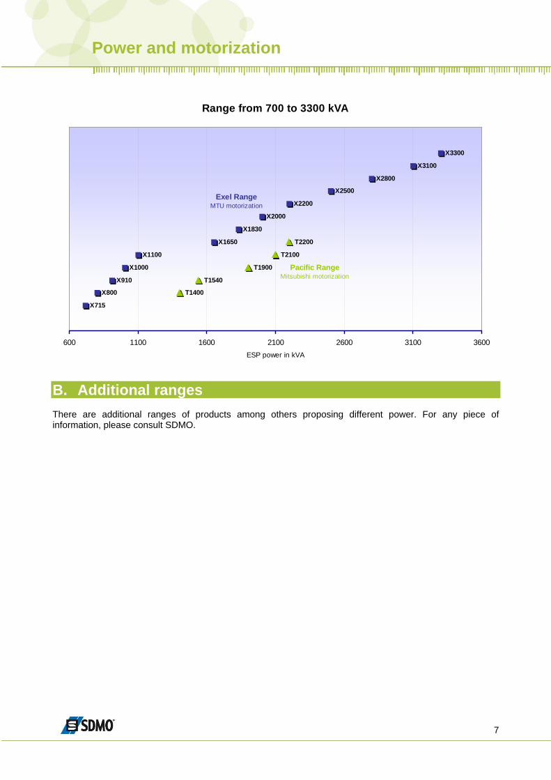
Range from 700 to 3300 kVA
X3300
X3100
X2800
X2500
X2200
X2000
X1830
X1650
X1100
X1000
X910
X800
X715
T2200
T2100
T1900
T1540
T1400
600 1100 1600 2100 2600 3100 3600ESP power in kVA
Exel RangeMTU motorization
Pacific RangeMitsubishi motorization
B. Additional ranges There are additional ranges of products among others proposing different power. For any piece of information, please consult SDMO.
Neutral system
8
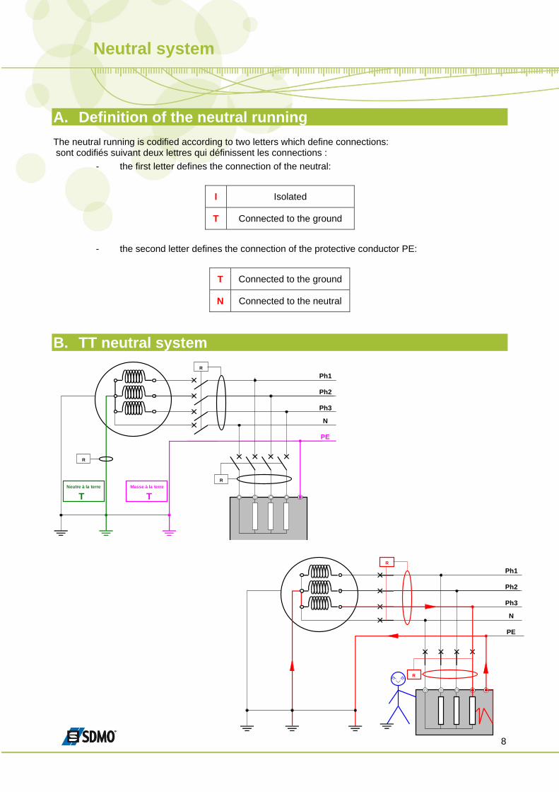
A. Definition of the neutral running The neutral running is codified according to two letters which define connections: sont codifiés suivant deux lettres qui définissent les connections :
- the first letter defines the connection of the neutral:
I Isolated
T Connected to the ground
- the second letter defines the connection of the protective conductor PE:
T Connected to the ground
N Connected to the neutral
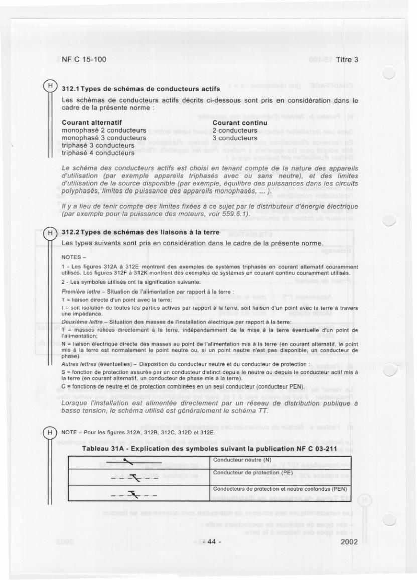
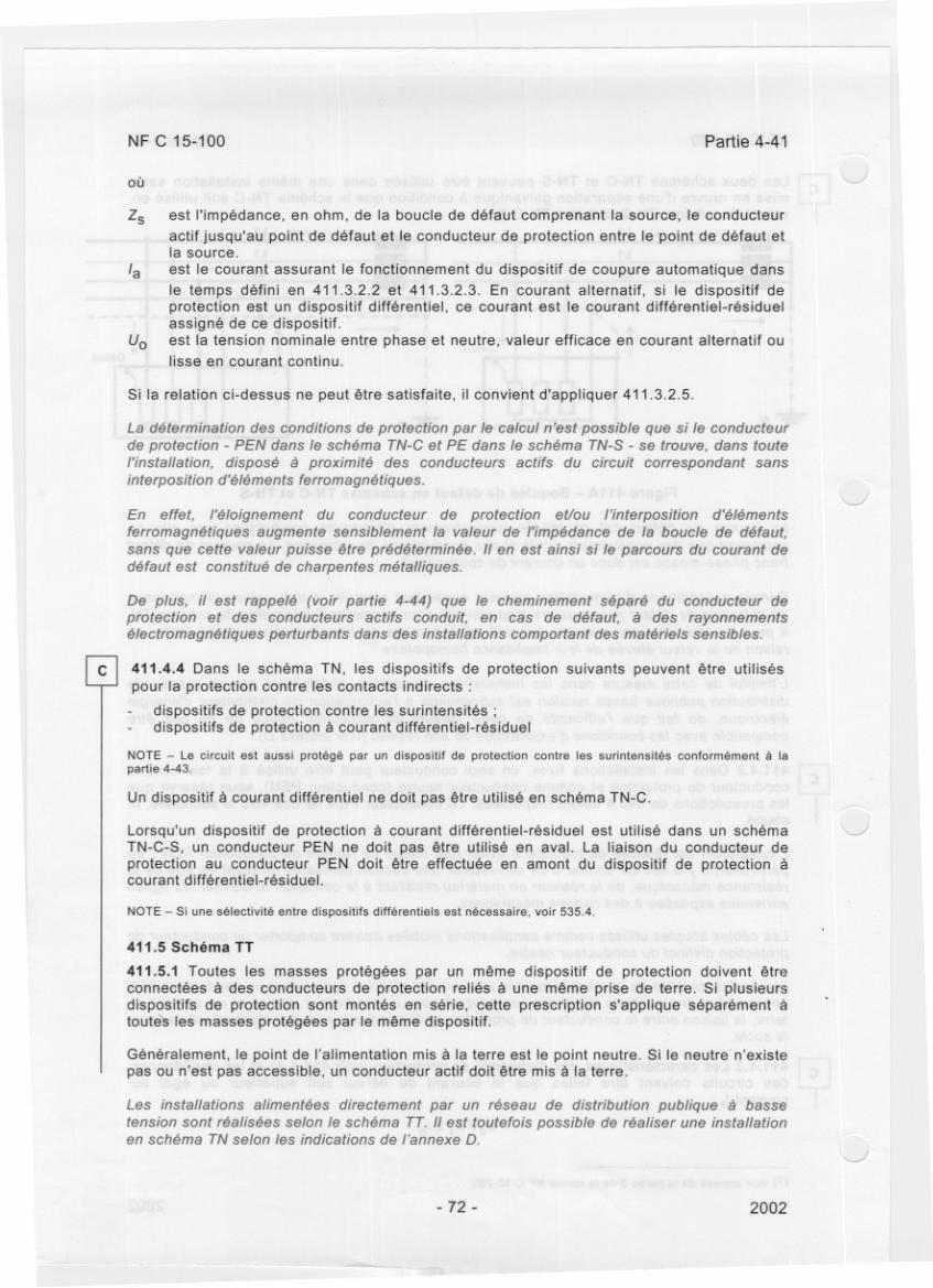
B. TT neutral system
Ph1
Ph2
Ph3
PE
N
T
Neutre à la terre
T
Masse à la terre
R
R
R
Ph1
Ph2
Ph3
PE
N
R
R
Neutral system
9
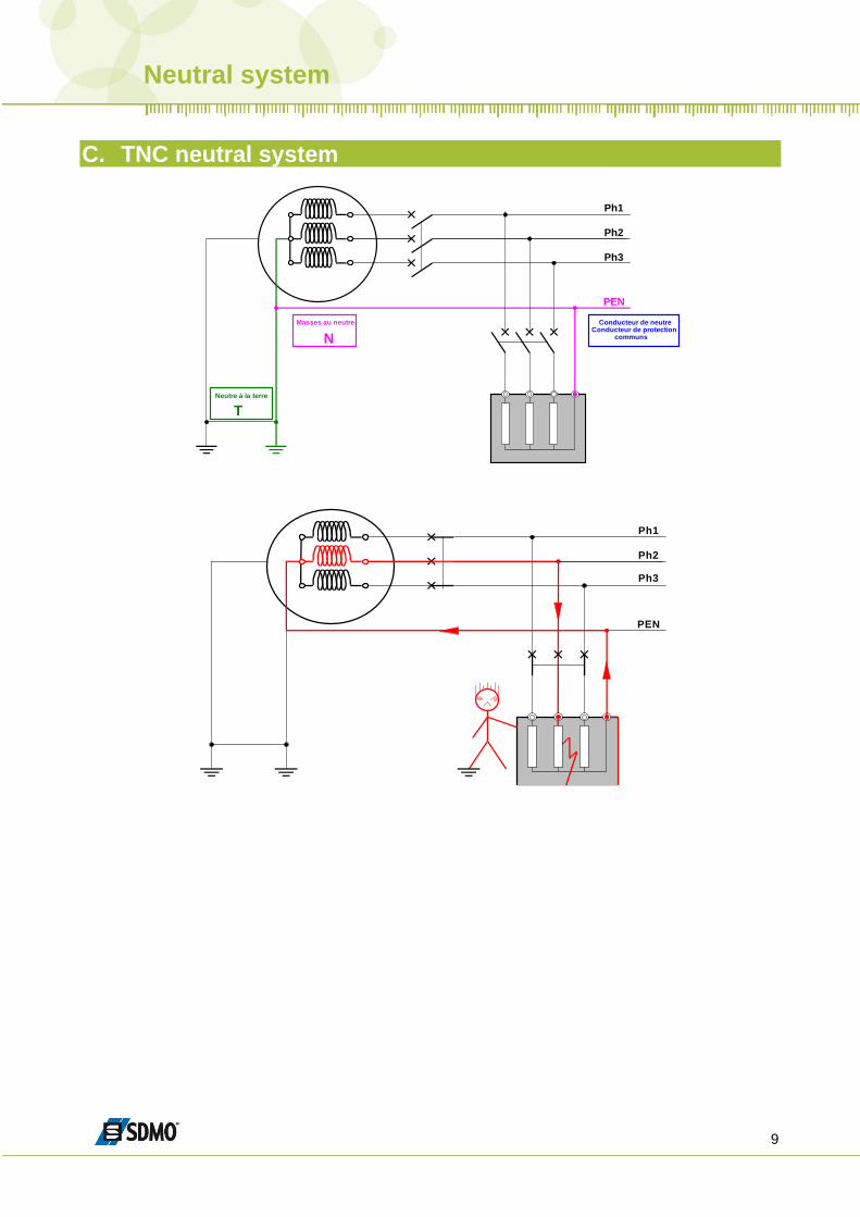
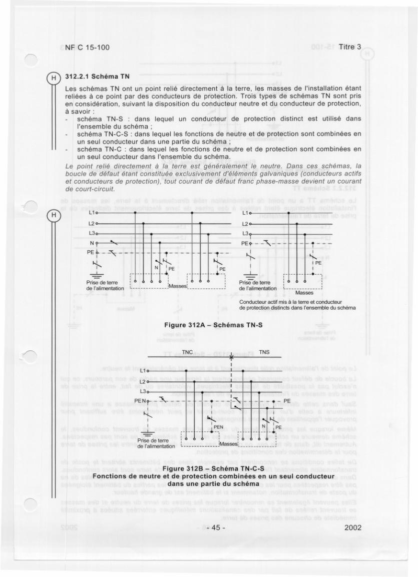
C. TNC neutral system
Ph1
Ph2
Ph3
PEN
Ph1
Ph2
Ph3
PEN
T
Neutre à la terre
N
Masses au neutre Conducteur de neutre Conducteur de protection
communs
Neutral system
10
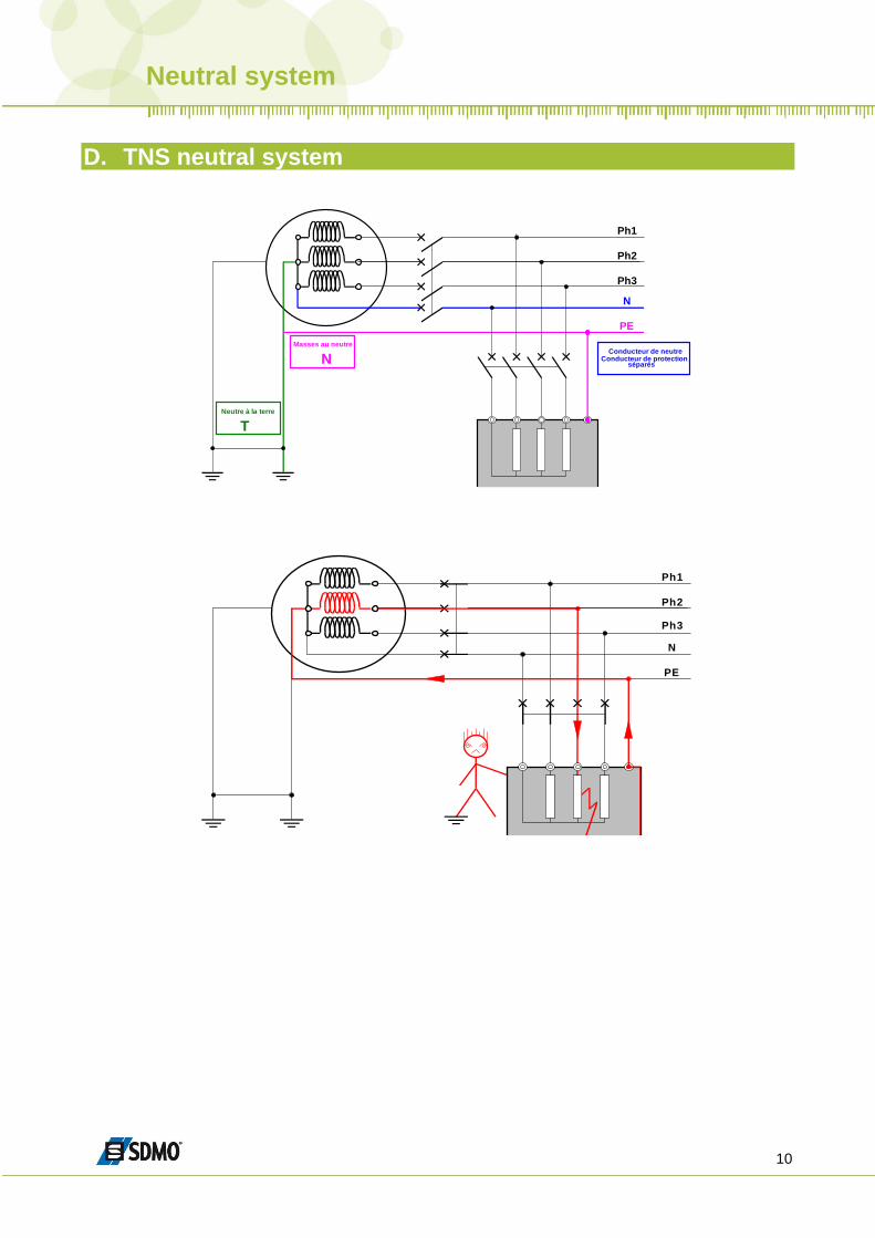
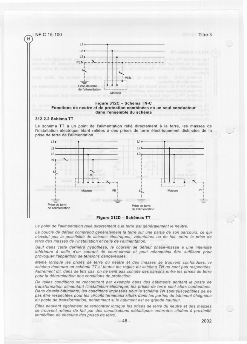
D. TNS neutral system
Ph1
Ph2
Ph3
PE
N
Ph1
Ph2
Ph3
PE
N
T
Neutre à la terre
N
Masses au neutre Conducteur de neutre
Conducteur de protection séparés
Neutral system
11
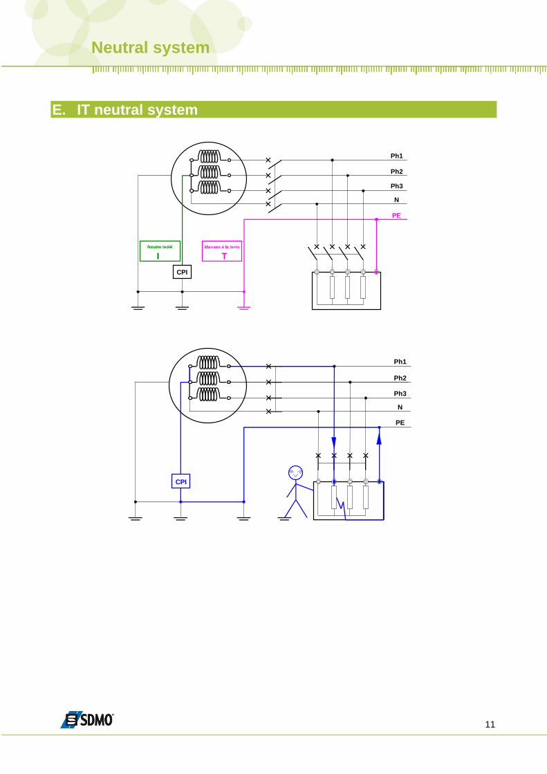
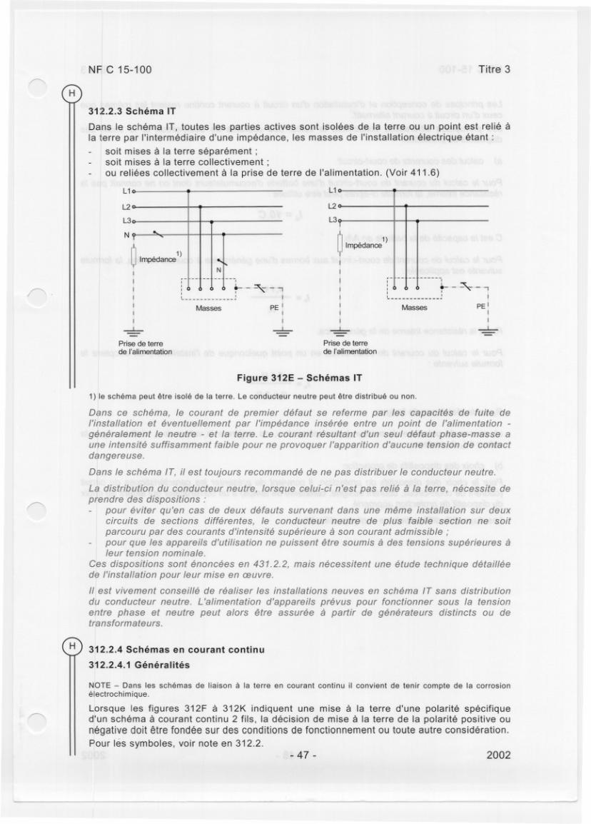
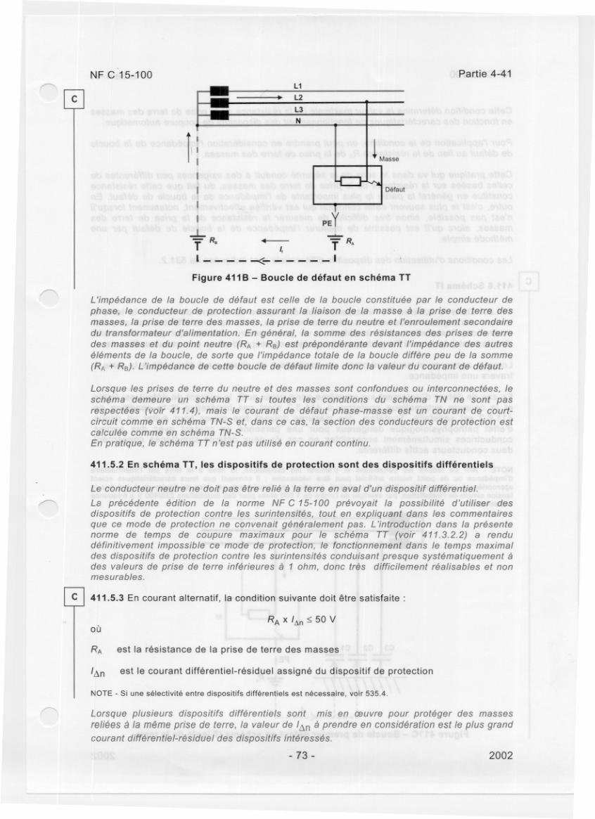
E. IT neutral system
Ph1
Ph2
Ph3
PE
N
CPI
Ph1
Ph2
Ph3
PE
CPI
N
I
Neutre isolé
T
Masses à la terre
Neutral system
12
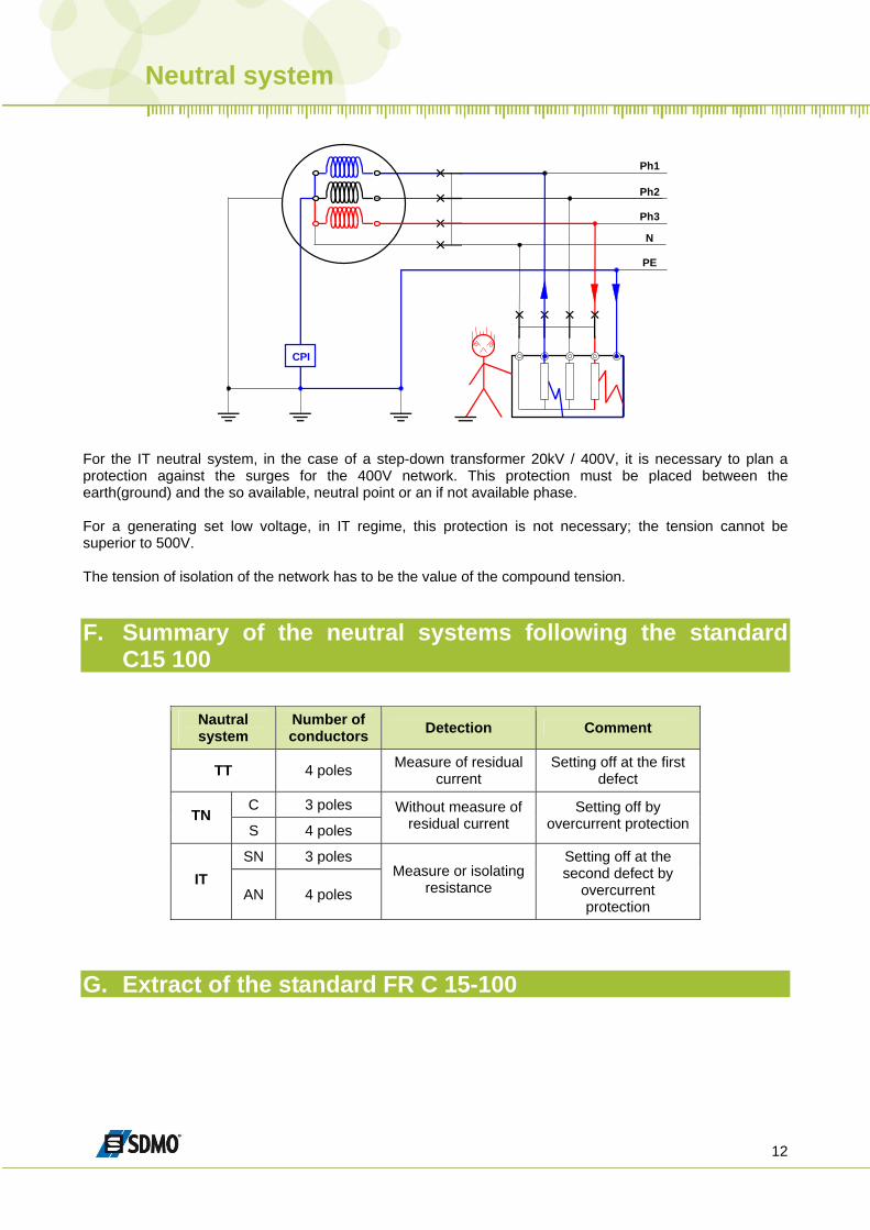
Ph1
Ph2
Ph3
PE
N
CPI
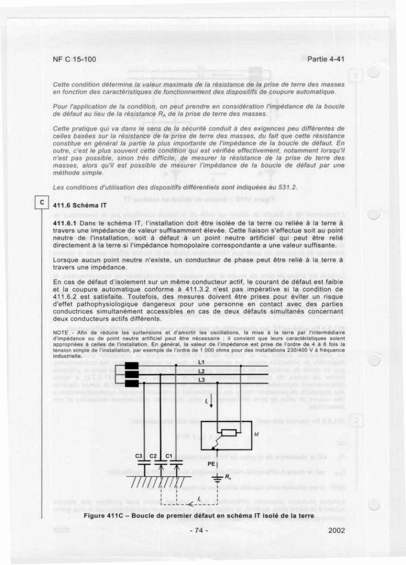
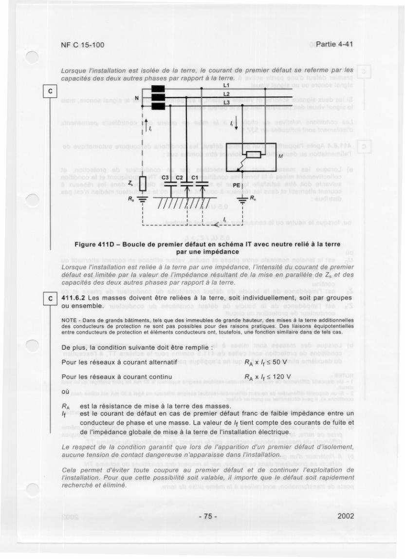
For the IT neutral system, in the case of a step-down transformer 20kV / 400V, it is necessary to plan a protection against the surges for the 400V network. This protection must be placed between the earth(ground) and the so available, neutral point or an if not available phase. For a generating set low voltage, in IT regime, this protection is not necessary; the tension cannot be superior to 500V. The tension of isolation of the network has to be the value of the compound tension.
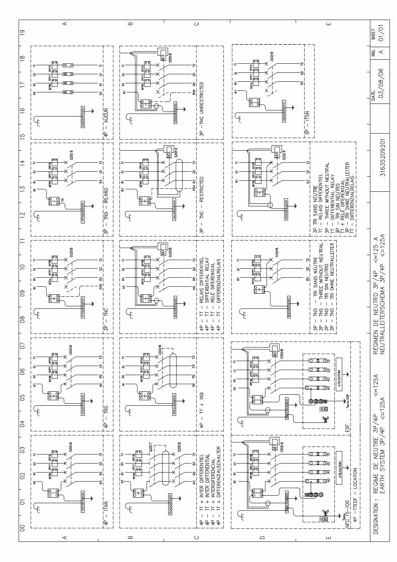
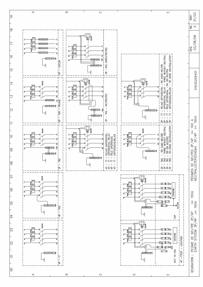
F. Summary of the neutral systems following the standard C15 100
Nautral system
Number of conductors Detection Comment
TT 4 poles Measure of residual current
Setting off at the first defect
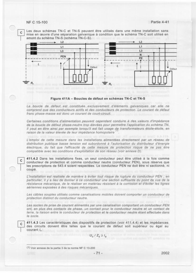
C 3 poles TN
S 4 poles Without measure of
residual current Setting off by
overcurrent protection
SN 3 poles IT
AN 4 poles Measure or isolating
resistance
Setting off at the second defect by
overcurrent protection
G. Extract of the standard FR C 15-100
Kerys configurations
27
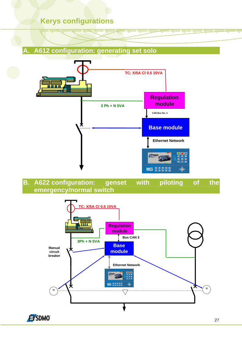
A. A612 configuration: generating set solo
Base module
TC: X/5A Cl 0.5 10VA
Ethernet Network
3 Ph + N 5VA
CAN Bus No. 3
Regulationmodule
B. A622 configuration: genset with piloting of the
emergency/normal switch
Base module
TC: X/5A Cl 0.5 10VA
Ethernet Network
3Ph + N 5VABus CAN 3
M M
Manualcircuit
breaker
Regulationmodule
Kerys configurations
28
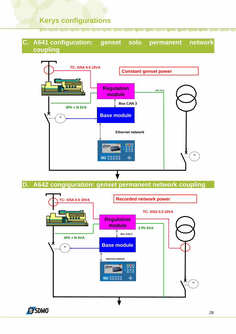
C. A641 configuration: genset solo permanent network
coupling
Base module
Regulationmodule
Ethernet network
3Ph + N 5VA
3Ph 5VA
TC: X/5A 0.5 10VA
Bus CAN 3
M
M
Constant genset power
D. A642 congiguration: genset permanent network coupling
Base module
Regulationmodule
TC: X/5A 0.5 10VA
Ethernet network
3Ph + N 5VA
TC: X/5A 0.5 10VA
3 Ph 5VABus CAN 3
M
Recorded network power
M
Kerys configurations
29
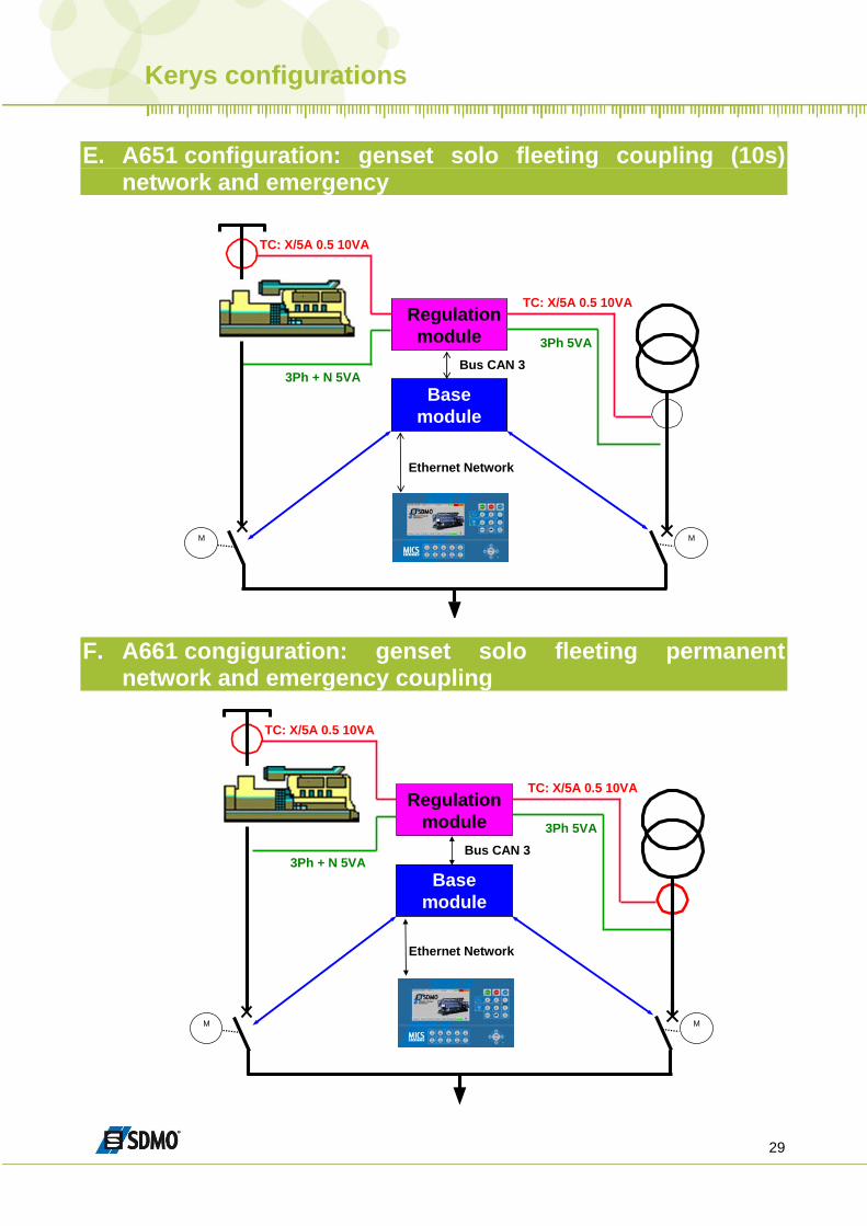
E. A651 configuration: genset solo fleeting coupling (10s)
network and emergency
Base module
Regulationmodule
TC: X/5A 0.5 10VA
Ethernet Network
3Ph + N 5VA
TC: X/5A 0.5 10VA
3Ph 5VABus CAN 3
MM
F. A661 congiguration: genset solo fleeting permanent
network and emergency coupling
Base module
Regulationmodule
TC: X/5A 0.5 10VA
Ethernet Network
3Ph + N 5VA
TC: X/5A 0.5 10VA
3Ph 5VABus CAN 3
MM
Kerys configurations
30
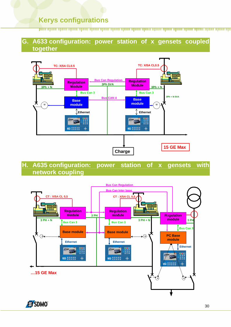
G. A633 configuration: power station of x gensets coupled
together
Base module
TC: X/5A CL0.5
Ethernet
3Ph + N Regulation
Module
Base module
TC: X/5A CL0.5
Ethernet
3Ph + N 5VA
M
RegulationModule3Ph 5VA
Bus Can Regulation
Bus CAN 4
MM
15 GE MaxCharge
Bus Can 3Bus Can 3
3Ph + N
H. A635 configuration: power station of x gensets with
network coupling
Base module
CT : X/5A CL 0,5
Ethernet
3 PH + N
M
Regulationmodule
Bus Can 3
Base module
CT : X/5A CL 0,5
Ethernet
3 PH + N
M
Regulationmodule3 PH
Bus Can 3
…15 GE Max
Bus Can Inter base
Bus Can Regulation
3 PH Regulation
module
PC Base module
Ethernet
Bus Can 3
MM
Protection and Normal/Emergency Switch
31
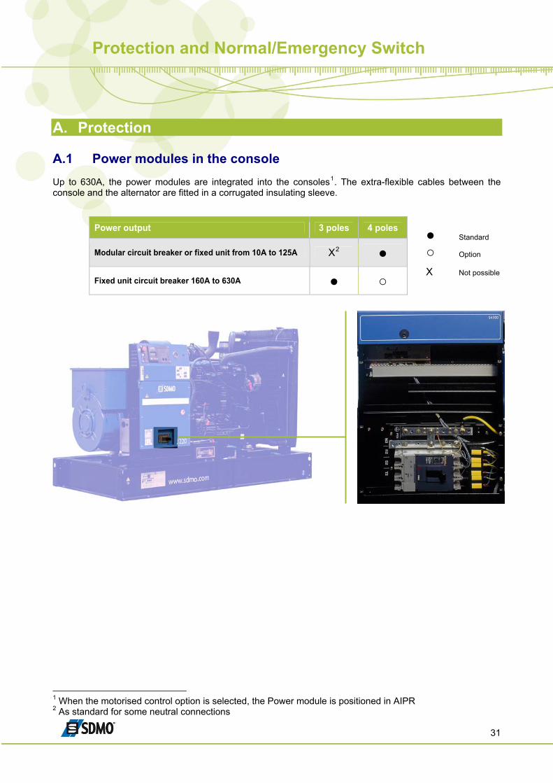
A. Protection A.1 Power modules in the console Up to 630A, the power modules are integrated into the consoles1. The extra-flexible cables between the console and the alternator are fitted in a corrugated insulating sleeve.
Power output 3 poles 4 poles
Modular circuit breaker or fixed unit from 10A to 125A X2 ● Fixed unit circuit breaker 160A to 630A ● ○
● Standard
○ Option X Not possible
1 When the motorised control option is selected, the Power module is positioned in AIPR 2 As standard for some neutral connections
Protection and Normal/Emergency Switch
32
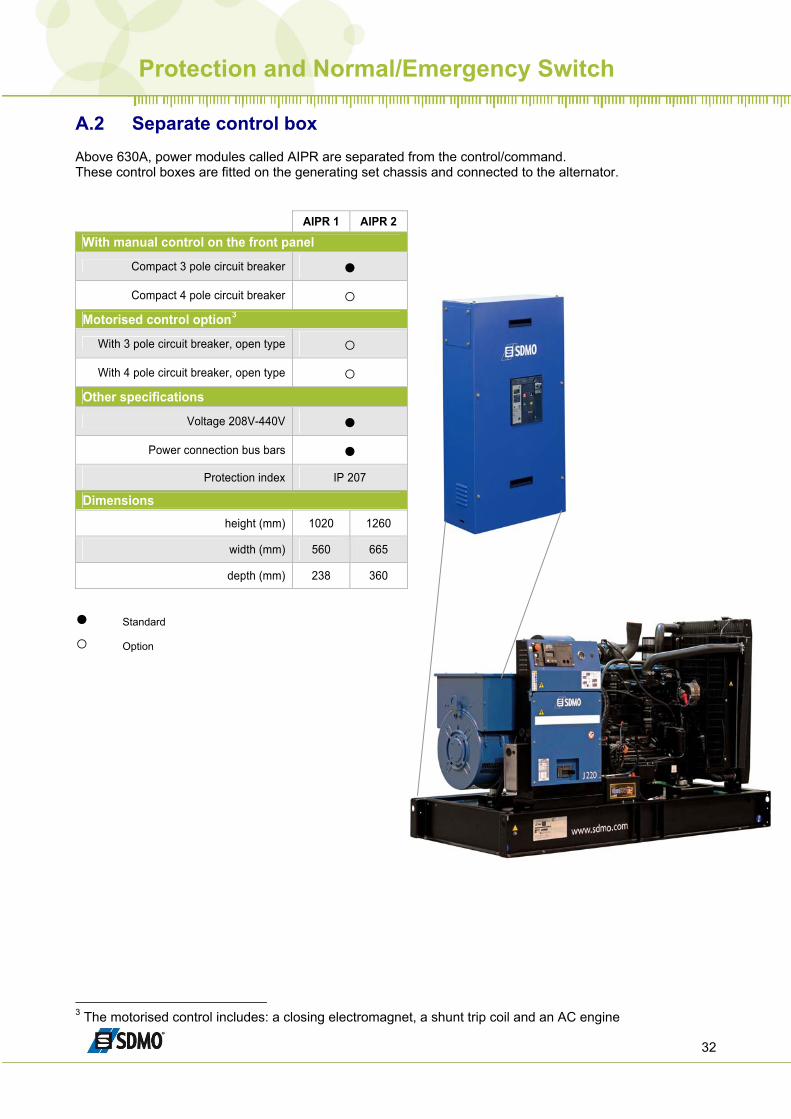
A.2 Separate control box Above 630A, power modules called AIPR are separated from the control/command. These control boxes are fitted on the generating set chassis and connected to the alternator.
AIPR 1 AIPR 2
With manual control on the front panel
Compact 3 pole circuit breaker ●
Compact 4 pole circuit breaker ○ Motorised control option3
With 3 pole circuit breaker, open type ○
With 4 pole circuit breaker, open type ○ Other specifications
Voltage 208V-440V ●
Power connection bus bars ● Protection index IP 207
Dimensions height (mm) 1020 1260
width (mm) 560 665
depth (mm) 238 360
● Standard
○ Option
3 The motorised control includes: a closing electromagnet, a shunt trip coil and an AC engine
Protection and Normal/Emergency Switch
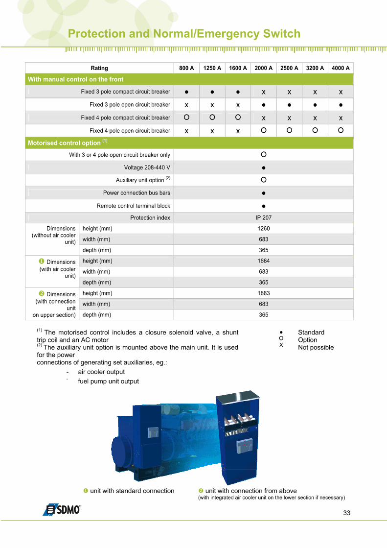
33
Rating 800 A 1250 A 1600 A 2000 A 2500 A 3200 A 4000 A
With manual control on the front
Fixed 3 pole compact circuit breaker ● ● ● x x x x Fixed 3 pole open circuit breaker x x x ● ● ● ●
Fixed 4 pole compact circuit breaker x x x x Fixed 4 pole open circuit breaker x x x
Motorised control option (1)
With 3 or 4 pole open circuit breaker only Voltage 208-440 V ●
Auxiliary unit option (2) Power connection bus bars ●
Remote control terminal block ● Protection index IP 207
height (mm) 1260
width (mm) 683
Dimensions (without air cooler
unit) depth (mm) 365
height (mm) 1664
width (mm) 683 Dimensions
(with air cooler unit)
depth (mm) 365
height (mm) 1883
width (mm) 683 Dimensions
(with connection unit
on upper section) depth (mm) 365
(1) The motorised control includes a closure solenoid valve, a shunt trip coil and an AC motor (2) The auxiliary unit option is mounted above the main unit. It is used for the power connections of generating set auxiliaries, eg.:
- air cooler output - fuel pump unit output
●
X
Standard Option Not possible
unit with standard connection unit with connection from above
(with integrated air cooler unit on the lower section if necessary)
Protection and Normal/Emergency Switch
34
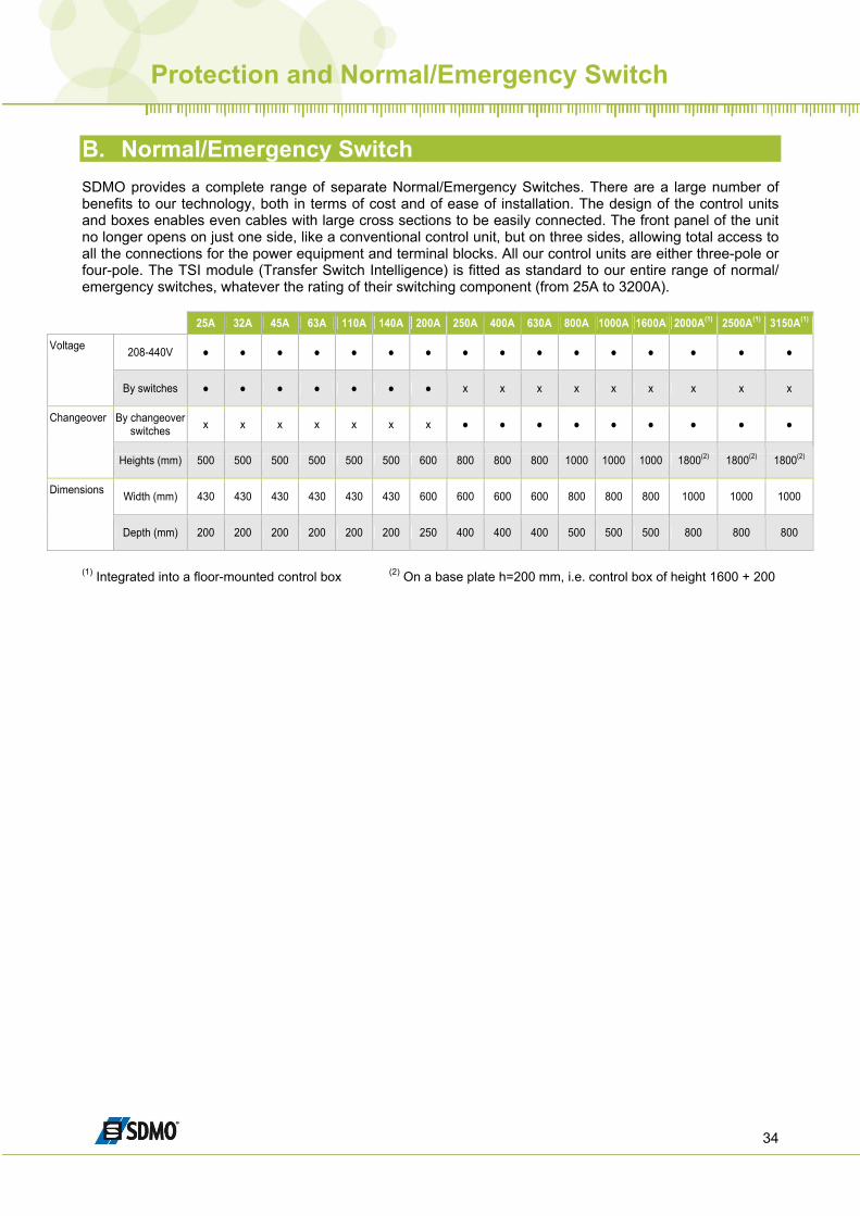
B. Normal/Emergency Switch SDMO provides a complete range of separate Normal/Emergency Switches. There are a large number of benefits to our technology, both in terms of cost and of ease of installation. The design of the control units and boxes enables even cables with large cross sections to be easily connected. The front panel of the unit no longer opens on just one side, like a conventional control unit, but on three sides, allowing total access to all the connections for the power equipment and terminal blocks. All our control units are either three-pole or four-pole. The TSI module (Transfer Switch Intelligence) is fitted as standard to our entire range of normal/ emergency switches, whatever the rating of their switching component (from 25A to 3200A).
25A 32A 45A 63A 110A 140A 200A 250A 400A 630A 800A 1000A 1600A 2000A(1) 2500A(1) 3150A(1)
208-440V ● ● ● ● ● ● ● ● ● ● ● ● ● ● ● ● Voltage
By switches ● ● ● ● ● ● ● x x x x x x x x x
By changeover switches x x x x x x x ● ● ● ● ● ● ● ● ● Changeover
Heights (mm) 500 500 500 500 500 500 600 800 800 800 1000 1000 1000 1800(2) 1800(2) 1800(2)
Width (mm) 430 430 430 430 430 430 600 600 600 600 800 800 800 1000 1000 1000 Dimensions
Depth (mm) 200 200 200 200 200 200 250 400 400 400 500 500 500 800 800 800
(1) Integrated into a floor-mounted control box (2) On a base plate h=200 mm, i.e. control box of height 1600 + 200
Canopies and containers
35
Noise reduction is one of the main argument for Gensets manufacturers, and perceived value for the products. SDMO makes a lot of investments to develop the most competitive products :
- Internal research in R&D - Measurement facilities investments (sound area, microphones and computers for sound
pressure and intensity measurements, people and training) - Prototypes for sound tests - Sound power check in production according to the 2000/14/EC regulation, with control by a
notified body.
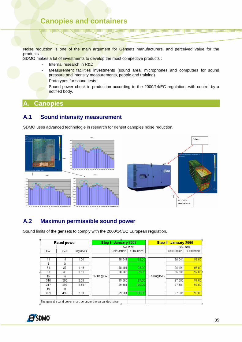
A. Canopies A.1 Sound intensity measurement SDMO uses advanced technologie in research for genset canopies noise reduction.
A.2 Maximun permissible sound power Sound limits of the gensets to comply with the 2000/14/EC European regulation.
Canopies and containers
36
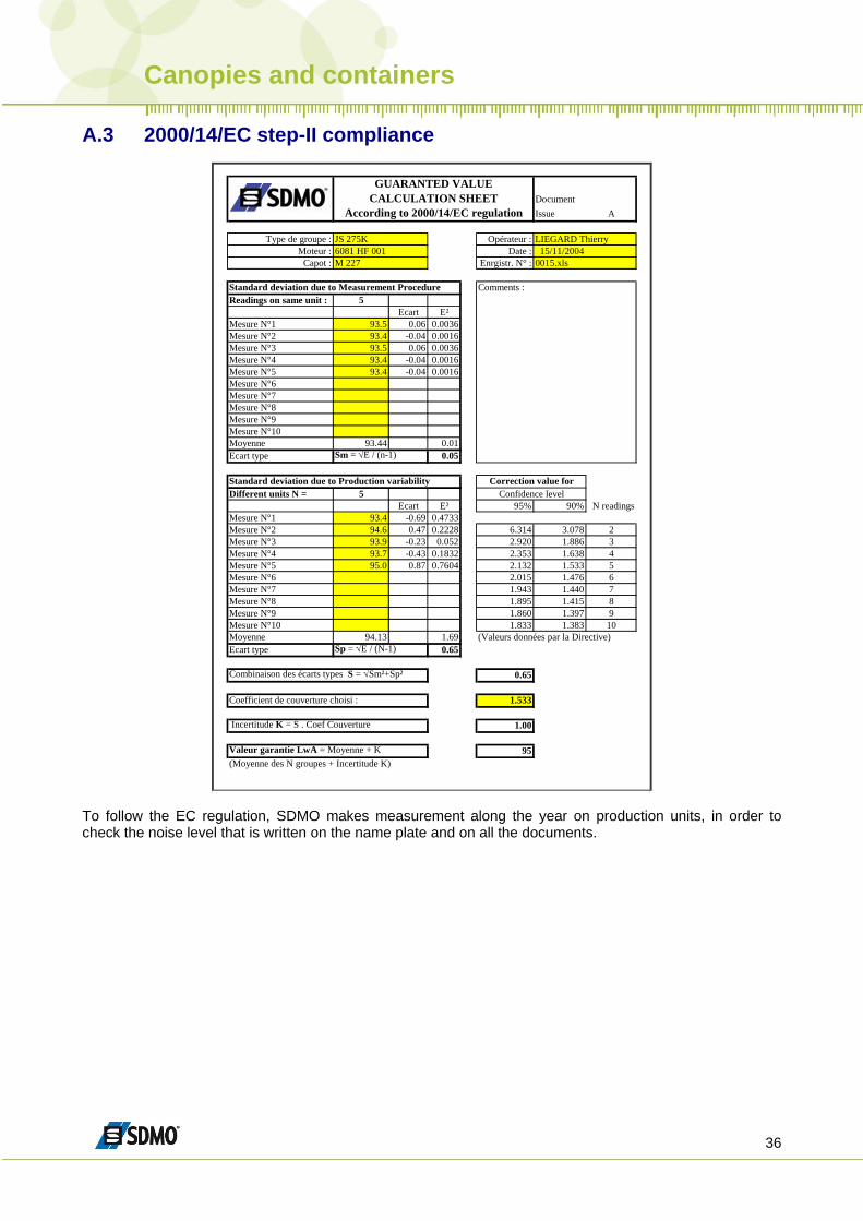
A.3 2000/14/EC step-II compliance
DocumentIssue A
Type de groupe : JS 275K Opérateur : LIEGARD ThierryMoteur : 6081 HF 001 Date : 15/11/2004
Capot : M 227 Enrgistr. N° : 0015.xls
Standard deviation due to Measurement Procedure Comments :Readings on same unit : 5
Ecart E²Mesure N°1 93.5 0.06 0.0036Mesure N°2 93.4 -0.04 0.0016Mesure N°3 93.5 0.06 0.0036Mesure N°4 93.4 -0.04 0.0016Mesure N°5 93.4 -0.04 0.0016Mesure N°6Mesure N°7Mesure N°8Mesure N°9Mesure N°10Moyenne 93.44 0.01Ecart type Sm = √E / (n-1) 0.05
Standard deviation due to Production variabilityDifferent units N = 5
Ecart E² 95% 90% N readingsMesure N°1 93.4 -0.69 0.4733Mesure N°2 94.6 0.47 0.2228 6.314 3.078 2Mesure N°3 93.9 -0.23 0.052 2.920 1.886 3Mesure N°4 93.7 -0.43 0.1832 2.353 1.638 4Mesure N°5 95.0 0.87 0.7604 2.132 1.533 5Mesure N°6 2.015 1.476 6Mesure N°7 1.943 1.440 7Mesure N°8 1.895 1.415 8Mesure N°9 1.860 1.397 9Mesure N°10 1.833 1.383 10Moyenne 94.13 1.69 (Valeurs données par la Directive)Ecart type Sp = √E / (N-1) 0.65
Combinaison des écarts types S = √Sm²+Sp² 0.65
Coefficient de couverture choisi : 1.533
Incertitude K = S . Coef Couverture 1.00
Valeur garantie LwA = Moyenne + K 95(Moyenne des N groupes + Incertitude K)
Confidence level
GUARANTED VALUECALCULATION SHEET
According to 2000/14/EC regulation
Correction value for
To follow the EC regulation, SDMO makes measurement along the year on production units, in order to check the noise level that is written on the name plate and on all the documents.
Canopies and containers
37
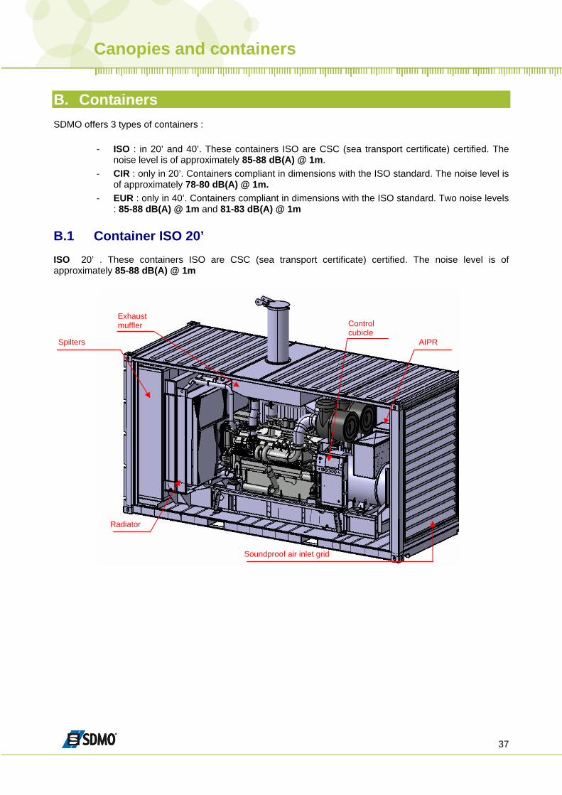
B. Containers SDMO offers 3 types of containers :
- ISO : in 20’ and 40’. These containers ISO are CSC (sea transport certificate) certified. The noise level is of approximately 85-88 dB(A) @ 1m.
- CIR : only in 20’. Containers compliant in dimensions with the ISO standard. The noise level is of approximately 78-80 dB(A) @ 1m.
- EUR : only in 40’. Containers compliant in dimensions with the ISO standard. Two noise levels : 85-88 dB(A) @ 1m and 81-83 dB(A) @ 1m
B.1 Container ISO 20’ ISO 20’ . These containers ISO are CSC (sea transport certificate) certified. The noise level is of approximately 85-88 dB(A) @ 1m
Exhaust muffler Control
cubicle AIPR
Radiator
Soundproof air inlet grid
Spilters
Canopies and containers
38
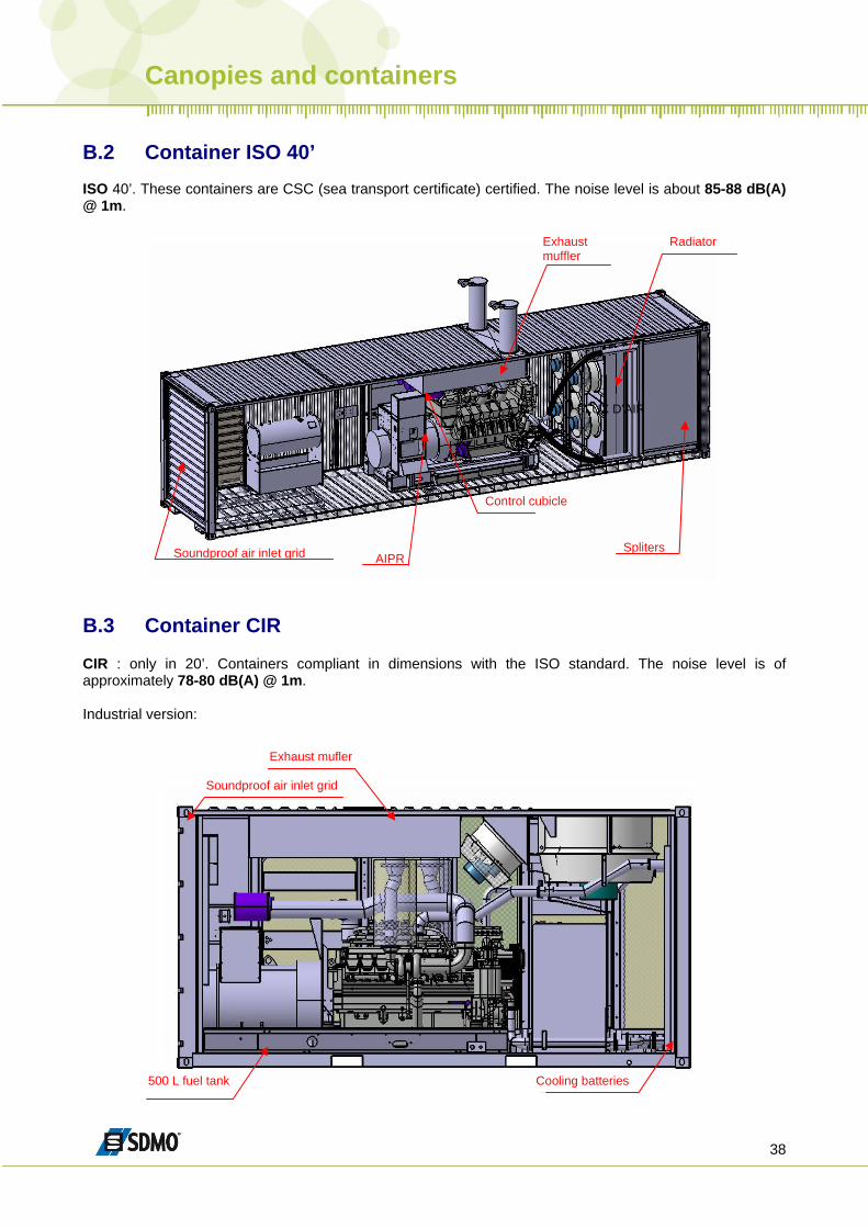
B.2 Container ISO 40’ ISO 40’. These containers are CSC (sea transport certificate) certified. The noise level is about 85-88 dB(A) @ 1m.
FLUX D’AIR
Exhaust muffler
Control cubicle
AIPR
Radiator
Spliters Soundproof air inlet grid
B.3 Container CIR CIR : only in 20’. Containers compliant in dimensions with the ISO standard. The noise level is of approximately 78-80 dB(A) @ 1m. Industrial version:
500 L fuel tank Cooling batteries
Exhaust mufler
Soundproof air inlet grid
Canopies and containers
39
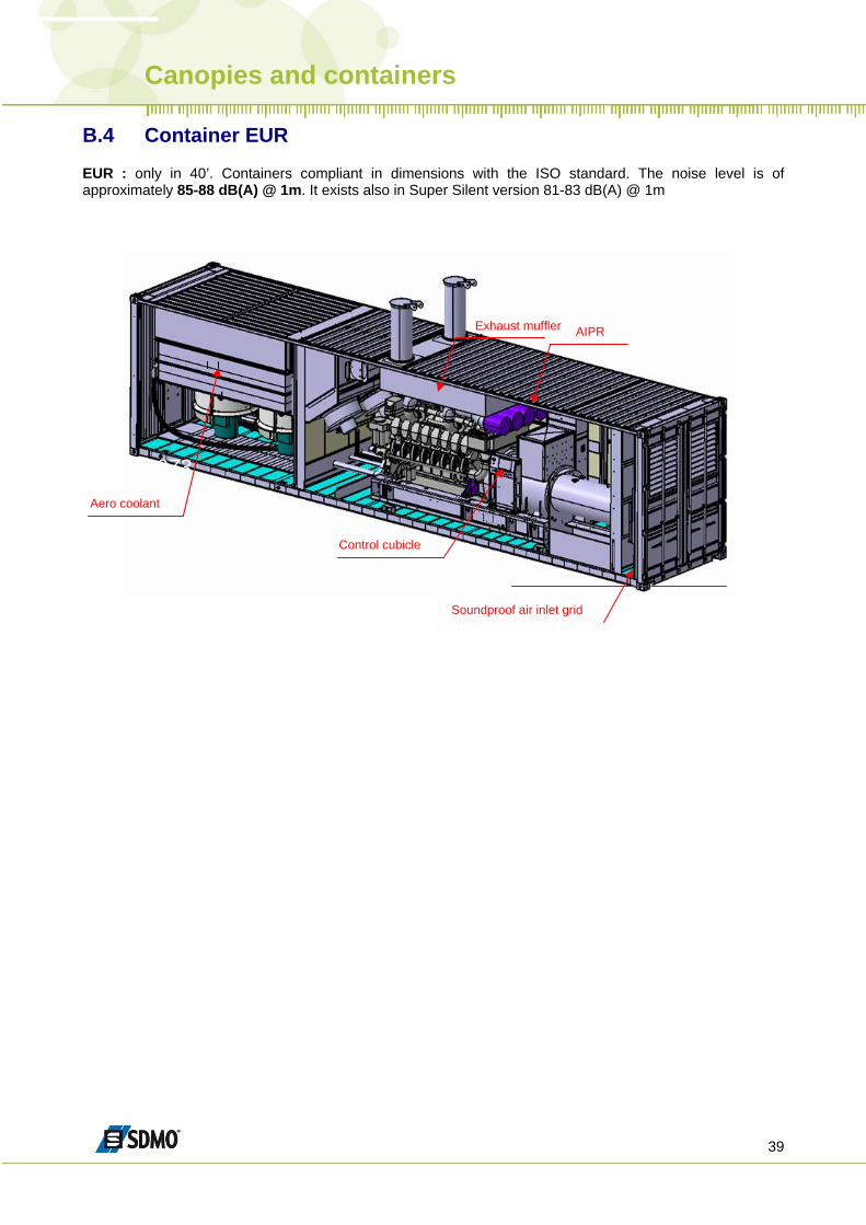
B.4 Container EUR EUR : only in 40’. Containers compliant in dimensions with the ISO standard. The noise level is of approximately 85-88 dB(A) @ 1m. It exists also in Super Silent version 81-83 dB(A) @ 1m
1970-1973
Exhaust muffler
Control cubicle
AIPR
Aero coolant
Soundproof air inlet grid
Exhaust
40
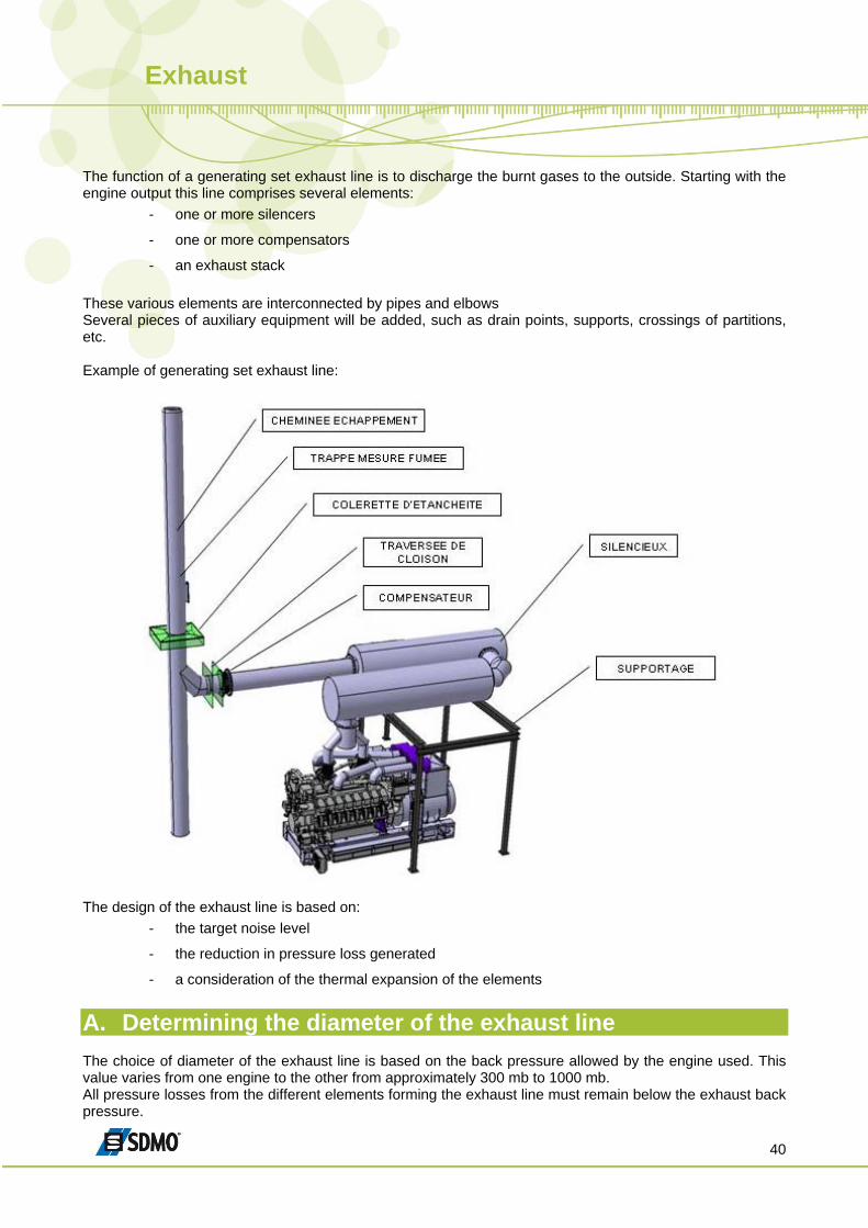
The function of a generating set exhaust line is to discharge the burnt gases to the outside. Starting with the engine output this line comprises several elements:
- one or more silencers
- one or more compensators
- an exhaust stack These various elements are interconnected by pipes and elbows Several pieces of auxiliary equipment will be added, such as drain points, supports, crossings of partitions, etc. Example of generating set exhaust line:
The design of the exhaust line is based on:
- the target noise level
- the reduction in pressure loss generated
- a consideration of the thermal expansion of the elements
A. Determining the diameter of the exhaust line The choice of diameter of the exhaust line is based on the back pressure allowed by the engine used. This value varies from one engine to the other from approximately 300 mb to 1000 mb. All pressure losses from the different elements forming the exhaust line must remain below the exhaust back pressure.
Exhaust
41
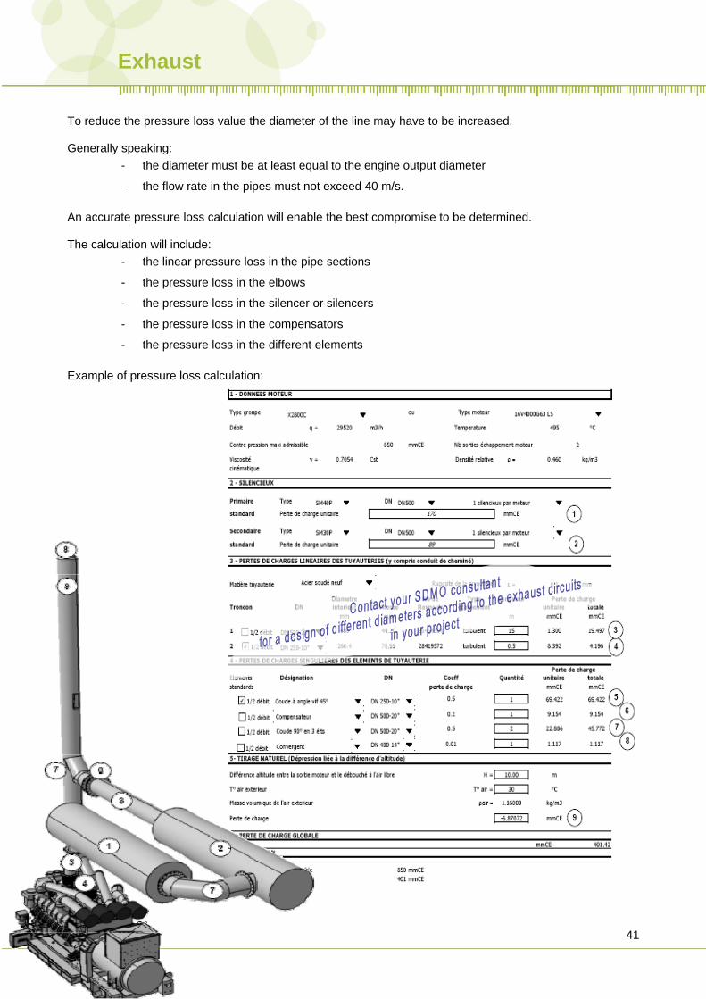
To reduce the pressure loss value the diameter of the line may have to be increased. Generally speaking:
- the diameter must be at least equal to the engine output diameter
- the flow rate in the pipes must not exceed 40 m/s. An accurate pressure loss calculation will enable the best compromise to be determined. The calculation will include:
- the linear pressure loss in the pipe sections
- the pressure loss in the elbows
- the pressure loss in the silencer or silencers
- the pressure loss in the compensators
- the pressure loss in the different elements Example of pressure loss calculation:
Exhaust
42
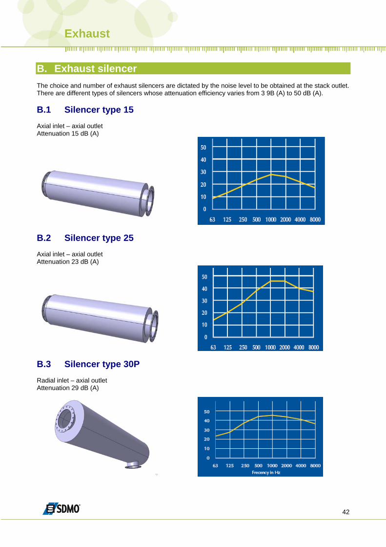
B. Exhaust silencer The choice and number of exhaust silencers are dictated by the noise level to be obtained at the stack outlet. There are different types of silencers whose attenuation efficiency varies from 3 9B (A) to 50 dB (A). B.1 Silencer type 15 Axial inlet – axial outlet Attenuation 15 dB (A)
B.2 Silencer type 25 Axial inlet – axial outlet Attenuation 23 dB (A)
B.3 Silencer type 30P Radial inlet – axial outlet Attenuation 29 dB (A)
Exhaust
43
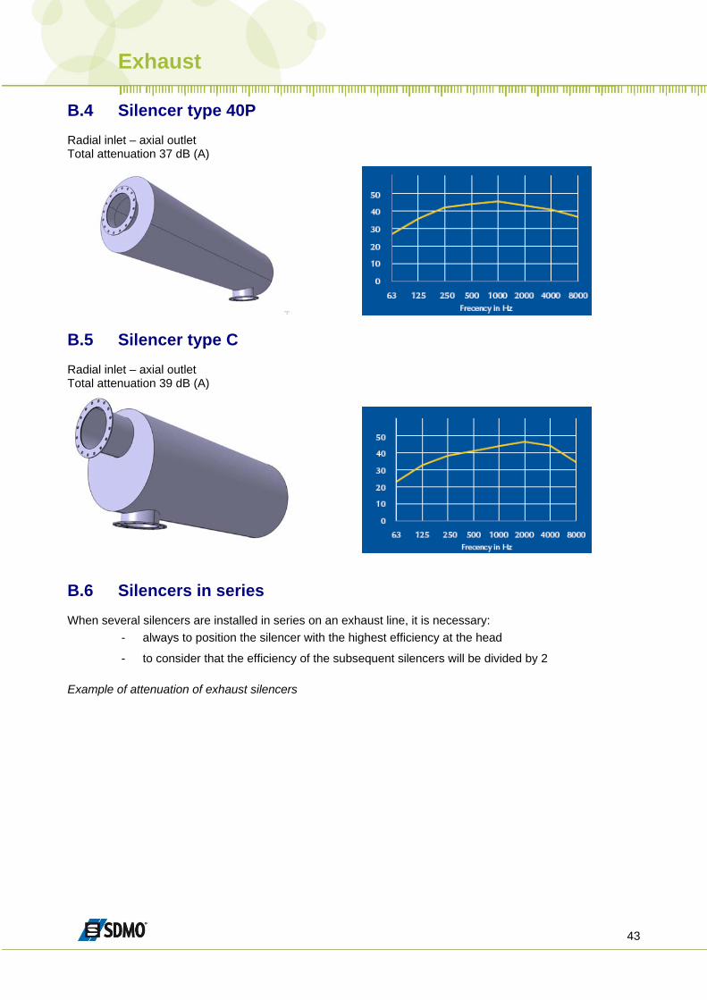
B.4 Silencer type 40P Radial inlet – axial outlet Total attenuation 37 dB (A)
B.5 Silencer type C Radial inlet – axial outlet Total attenuation 39 dB (A)
B.6 Silencers in series When several silencers are installed in series on an exhaust line, it is necessary:
- always to position the silencer with the highest efficiency at the head
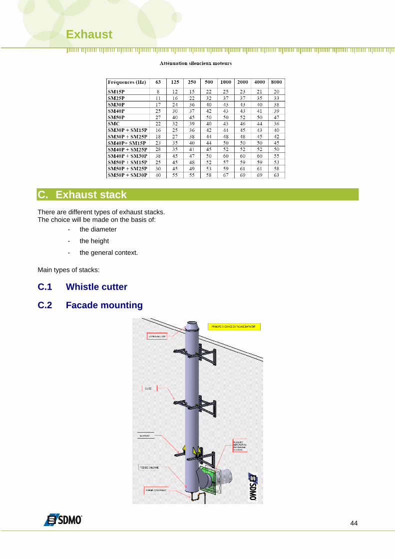
- to consider that the efficiency of the subsequent silencers will be divided by 2 Example of attenuation of exhaust silencers
Exhaust
44
C. Exhaust stack There are different types of exhaust stacks. The choice will be made on the basis of:
- the diameter
- the height
- the general context. Main types of stacks: C.1 Whistle cutter C.2 Facade mounting
Exhaust
45
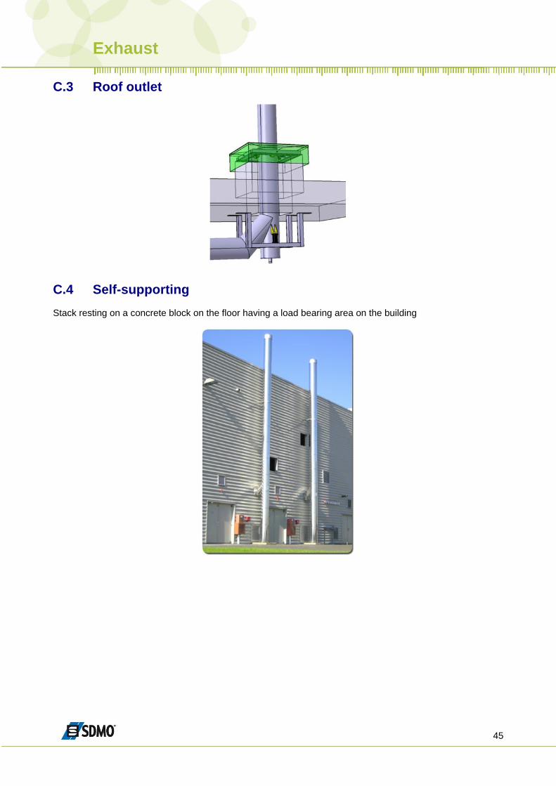
C.3 Roof outlet
C.4 Self-supporting Stack resting on a concrete block on the floor having a load bearing area on the building
Exhaust
46
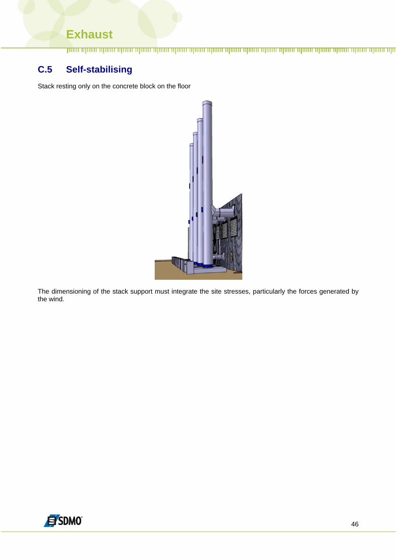
C.5 Self-stabilising Stack resting only on the concrete block on the floor
The dimensioning of the stack support must integrate the site stresses, particularly the forces generated by the wind.
Exhaust
47
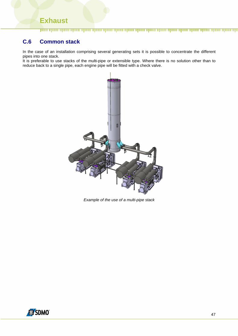
C.6 Common stack In the case of an installation comprising several generating sets it is possible to concentrate the different pipes into one stack. It is preferable to use stacks of the multi-pipe or extensible type. Where there is no solution other than to reduce back to a single pipe, each engine pipe will be fitted with a check valve.
Example of the use of a multi-pipe stack
Exhaust
48
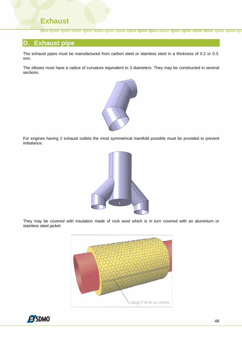
D. Exhaust pipe The exhaust pipes must be manufactured from carbon steel or stainless steel in a thickness of 0.2 or 0.3. mm. The elbows must have a radius of curvature equivalent to 3 diameters. They may be constructed in several sections.
For engines having 2 exhaust outlets the most symmetrical manifold possible must be provided to prevent imbalance.
They may be covered with insulation made of rock wool which is in turn covered with an aluminium or stainless steel jacket.
Exhaust
49
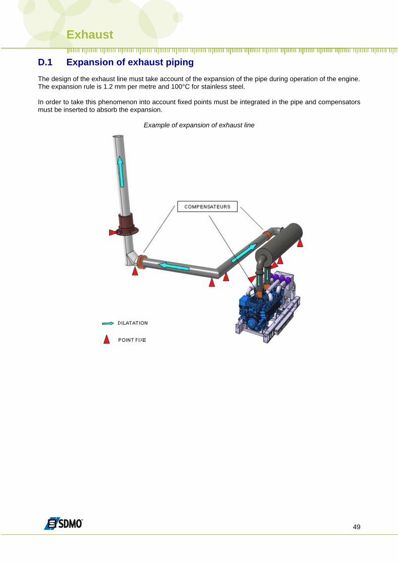
D.1 Expansion of exhaust piping The design of the exhaust line must take account of the expansion of the pipe during operation of the engine. The expansion rule is 1.2 mm per metre and 100°C for stainless steel. In order to take this phenomenon into account fixed points must be integrated in the pipe and compensators must be inserted to absorb the expansion.
Example of expansion of exhaust line
Exhaust
50
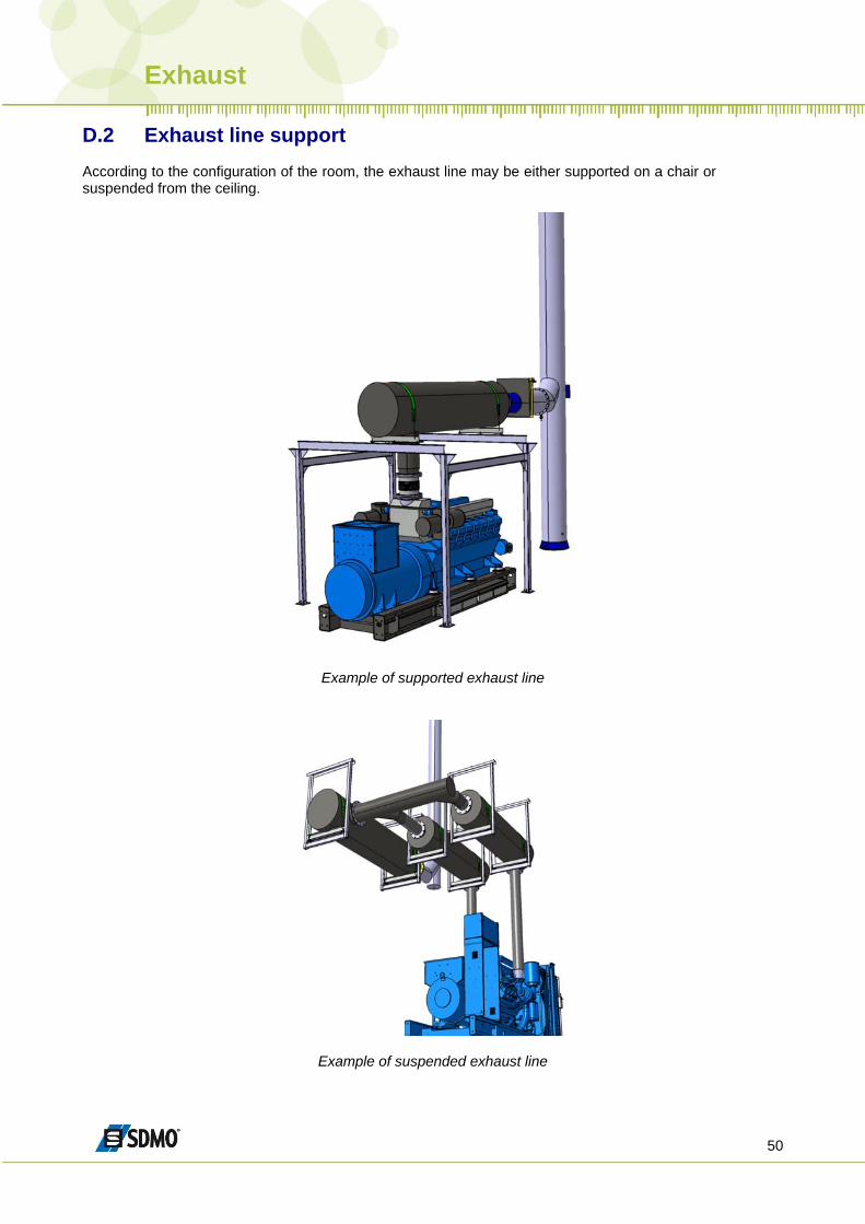
D.2 Exhaust line support
According to the configuration of the room, the exhaust line may be either supported on a chair or suspended from the ceiling.
Example of supported exhaust line
Example of suspended exhaust line
Fuel
51
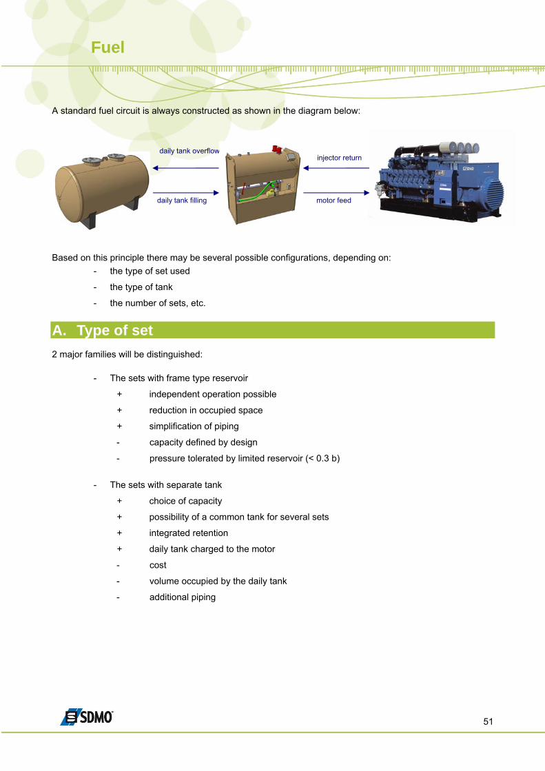
A standard fuel circuit is always constructed as shown in the diagram below:
injector return
motor feed
daily tank overflow
daily tank filling
Based on this principle there may be several possible configurations, depending on:
- the type of set used
- the type of tank
- the number of sets, etc.
A. Type of set 2 major families will be distinguished:
- The sets with frame type reservoir
+ independent operation possible
+ reduction in occupied space
+ simplification of piping
- capacity defined by design
- pressure tolerated by limited reservoir (< 0.3 b)
- The sets with separate tank
+ choice of capacity
+ possibility of a common tank for several sets
+ integrated retention
+ daily tank charged to the motor
- cost
- volume occupied by the daily tank
- additional piping
Fuel
52
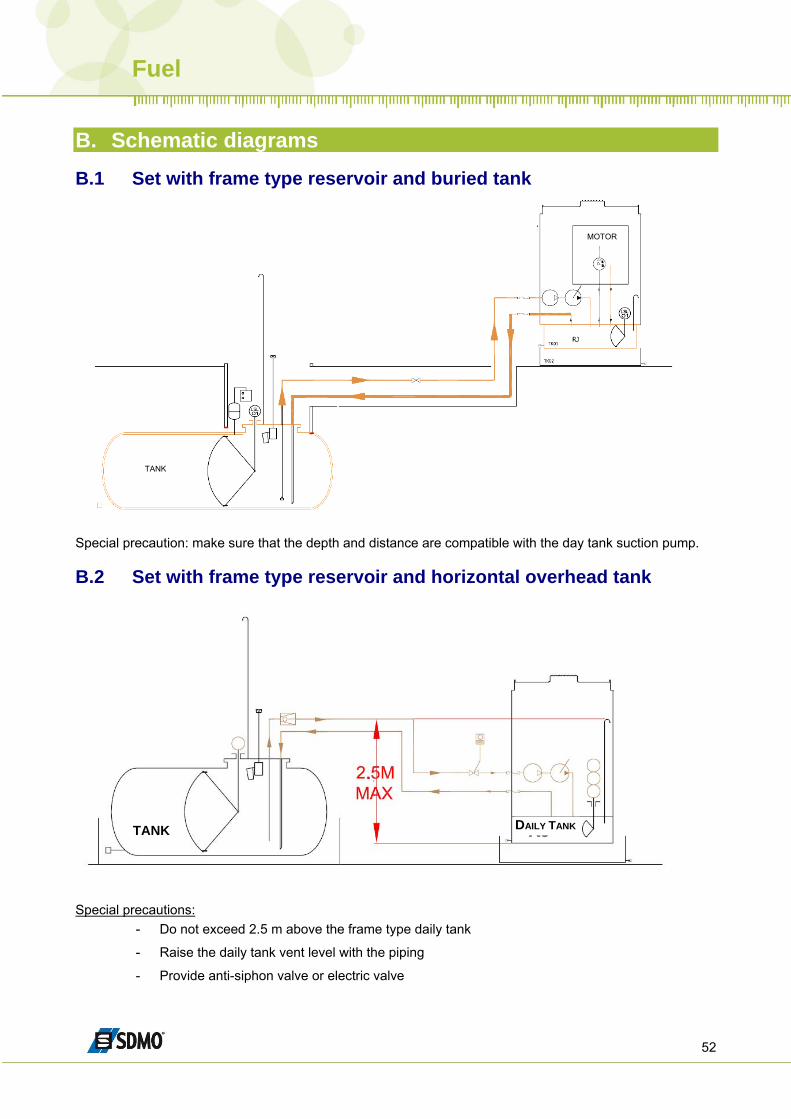
B. Schematic diagrams B.1 Set with frame type reservoir and buried tank
TANK
MOTOR
Special precaution: make sure that the depth and distance are compatible with the day tank suction pump. B.2 Set with frame type reservoir and horizontal overhead tank
DAILY TANK TANK
Special precautions:
- Do not exceed 2.5 m above the frame type daily tank
- Raise the daily tank vent level with the piping
- Provide anti-siphon valve or electric valve
Fuel
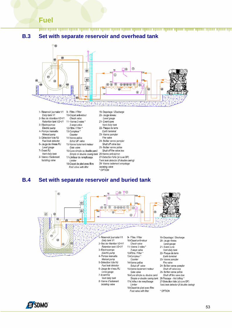
53
B.3 Set with separate reservoir and overhead tank
B.4 Set with separate reservoir and buried tank
Fuel
54
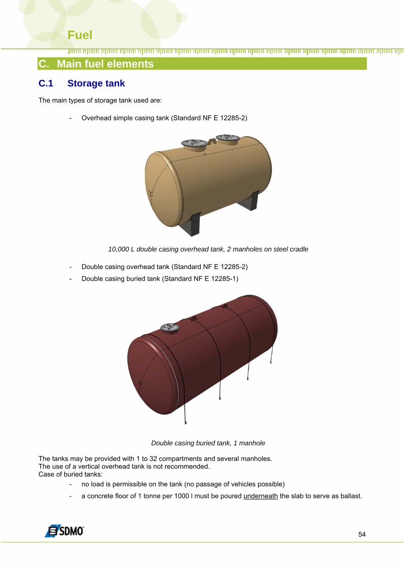
C. Main fuel elements C.1 Storage tank The main types of storage tank used are:
- Overhead simple casing tank (Standard NF E 12285-2)
10,000 L double casing overhead tank, 2 manholes on steel cradle
- Double casing overhead tank (Standard NF E 12285-2)
- Double casing buried tank (Standard NF E 12285-1)
Double casing buried tank, 1 manhole The tanks may be provided with 1 to 32 compartments and several manholes. The use of a vertical overhead tank is not recommended. Case of buried tanks:
- no load is permissible on the tank (no passage of vehicles possible)
- a concrete floor of 1 tonne per 1000 l must be poured underneath the slab to serve as ballast.
Fuel
55
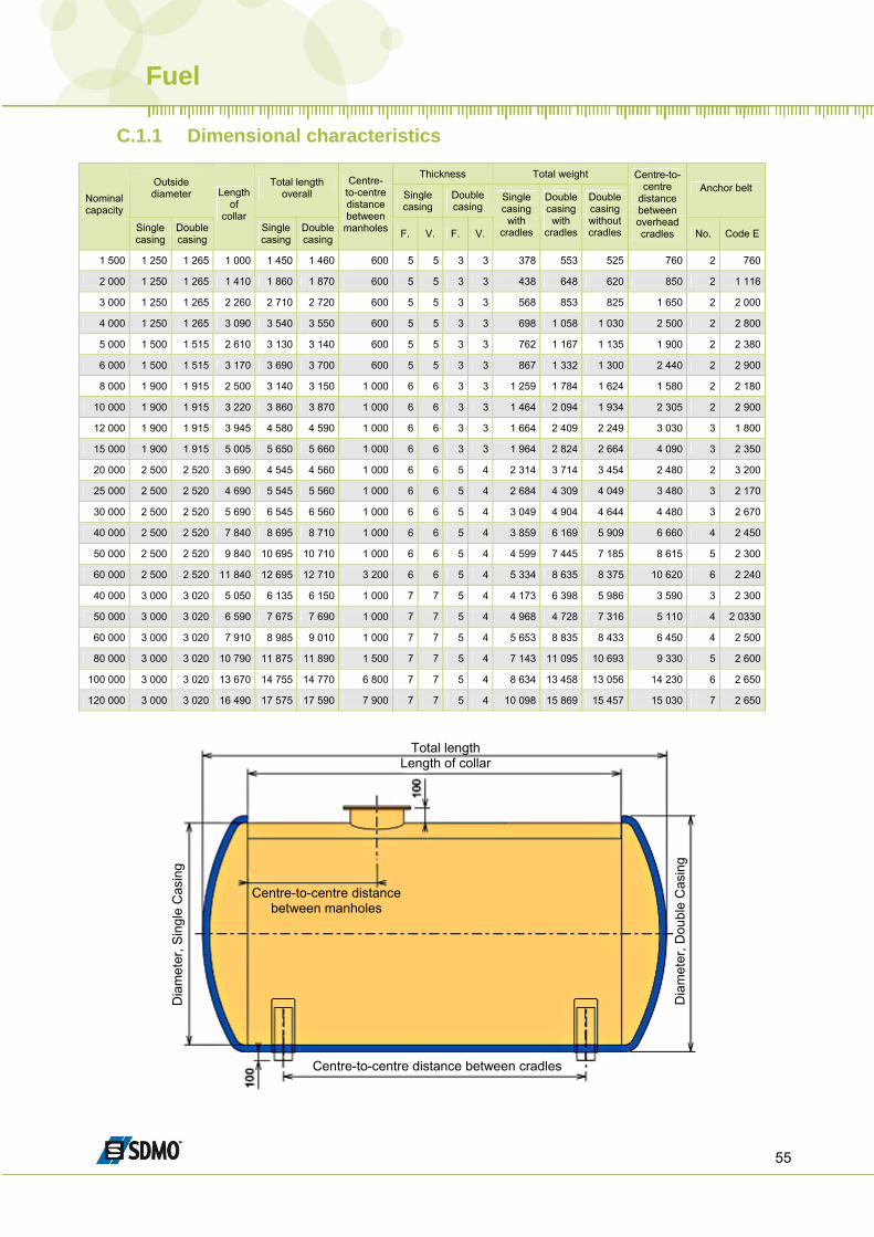
C.1.1 Dimensional characteristics
Thickness Total weight Outside diameter
Total length overall Single
casing Double casing
Anchor belt Nominal capacity
Single casing
Double casing
Length of
collar Single casing
Double casing
Centre-to-centre distance between
manholes F. V. F. V.
Single casing
with cradles
Double casing with
cradles
Double casing without cradles
Centre-to-centre
distance between overhead cradles No. Code E
1 500 1 250 1 265 1 000 1 450 1 460 600 5 5 3 3 378 553 525 760 2 760
2 000 1 250 1 265 1 410 1 860 1 870 600 5 5 3 3 438 648 620 850 2 1 116
3 000 1 250 1 265 2 260 2 710 2 720 600 5 5 3 3 568 853 825 1 650 2 2 000
4 000 1 250 1 265 3 090 3 540 3 550 600 5 5 3 3 698 1 058 1 030 2 500 2 2 800
5 000 1 500 1 515 2 610 3 130 3 140 600 5 5 3 3 762 1 167 1 135 1 900 2 2 380
6 000 1 500 1 515 3 170 3 690 3 700 600 5 5 3 3 867 1 332 1 300 2 440 2 2 900
8 000 1 900 1 915 2 500 3 140 3 150 1 000 6 6 3 3 1 259 1 784 1 624 1 580 2 2 180
10 000 1 900 1 915 3 220 3 860 3 870 1 000 6 6 3 3 1 464 2 094 1 934 2 305 2 2 900
12 000 1 900 1 915 3 945 4 580 4 590 1 000 6 6 3 3 1 664 2 409 2 249 3 030 3 1 800
15 000 1 900 1 915 5 005 5 650 5 660 1 000 6 6 3 3 1 964 2 824 2 664 4 090 3 2 350
20 000 2 500 2 520 3 690 4 545 4 560 1 000 6 6 5 4 2 314 3 714 3 454 2 480 2 3 200
25 000 2 500 2 520 4 690 5 545 5 560 1 000 6 6 5 4 2 684 4 309 4 049 3 480 3 2 170
30 000 2 500 2 520 5 690 6 545 6 560 1 000 6 6 5 4 3 049 4 904 4 644 4 480 3 2 670
40 000 2 500 2 520 7 840 8 695 8 710 1 000 6 6 5 4 3 859 6 169 5 909 6 660 4 2 450
50 000 2 500 2 520 9 840 10 695 10 710 1 000 6 6 5 4 4 599 7 445 7 185 8 615 5 2 300
60 000 2 500 2 520 11 840 12 695 12 710 3 200 6 6 5 4 5 334 8 635 8 375 10 620 6 2 240
40 000 3 000 3 020 5 050 6 135 6 150 1 000 7 7 5 4 4 173 6 398 5 986 3 590 3 2 300
50 000 3 000 3 020 6 590 7 675 7 690 1 000 7 7 5 4 4 968 4 728 7 316 5 110 4 2 0330
60 000 3 000 3 020 7 910 8 985 9 010 1 000 7 7 5 4 5 653 8 835 8 433 6 450 4 2 500
80 000 3 000 3 020 10 790 11 875 11 890 1 500 7 7 5 4 7 143 11 095 10 693 9 330 5 2 600
100 000 3 000 3 020 13 670 14 755 14 770 6 800 7 7 5 4 8 634 13 458 13 056 14 230 6 2 650
120 000 3 000 3 020 16 490 17 575 17 590 7 900 7 7 5 4 10 098 15 869 15 457 15 030 7 2 650
Total length Length of collar
Centre-to-centre distance between manholes
Dia
met
er, S
ingl
e C
asin
g
Centre-to-centre distance between cradles
Dia
met
er, D
oubl
e C
asin
g
Fuel
56
C.2 Tank equipment
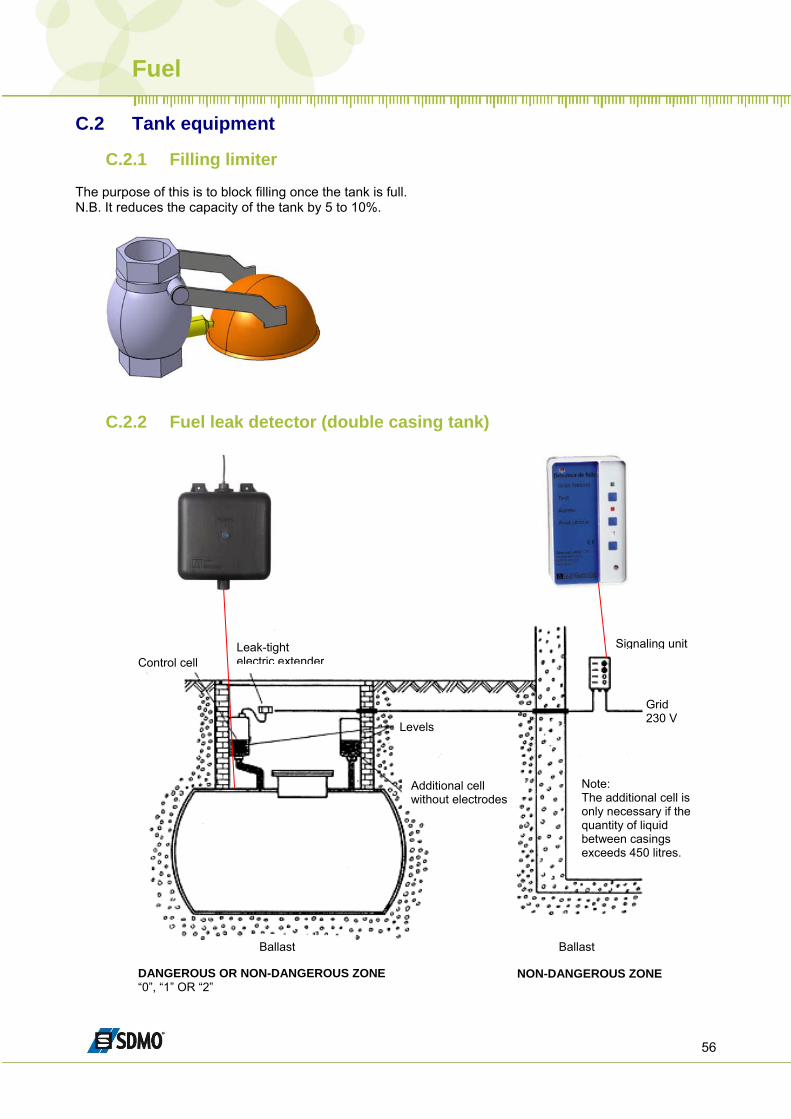
C.2.1 Filling limiter The purpose of this is to block filling once the tank is full. N.B. It reduces the capacity of the tank by 5 to 10%.
C.2.2 Fuel leak detector (double casing tank)
Control cell Leak-tight electric extender
Signaling unit
Grid 230 V
Levels
Additional cell without electrodes
Ballast Ballast
Note: The additional cell is only necessary if the quantity of liquid between casings exceeds 450 litres.
DANGEROUS OR NON-DANGEROUS ZONE“0”, “1” OR “2”
NON-DANGEROUS ZONE
Fuel
57
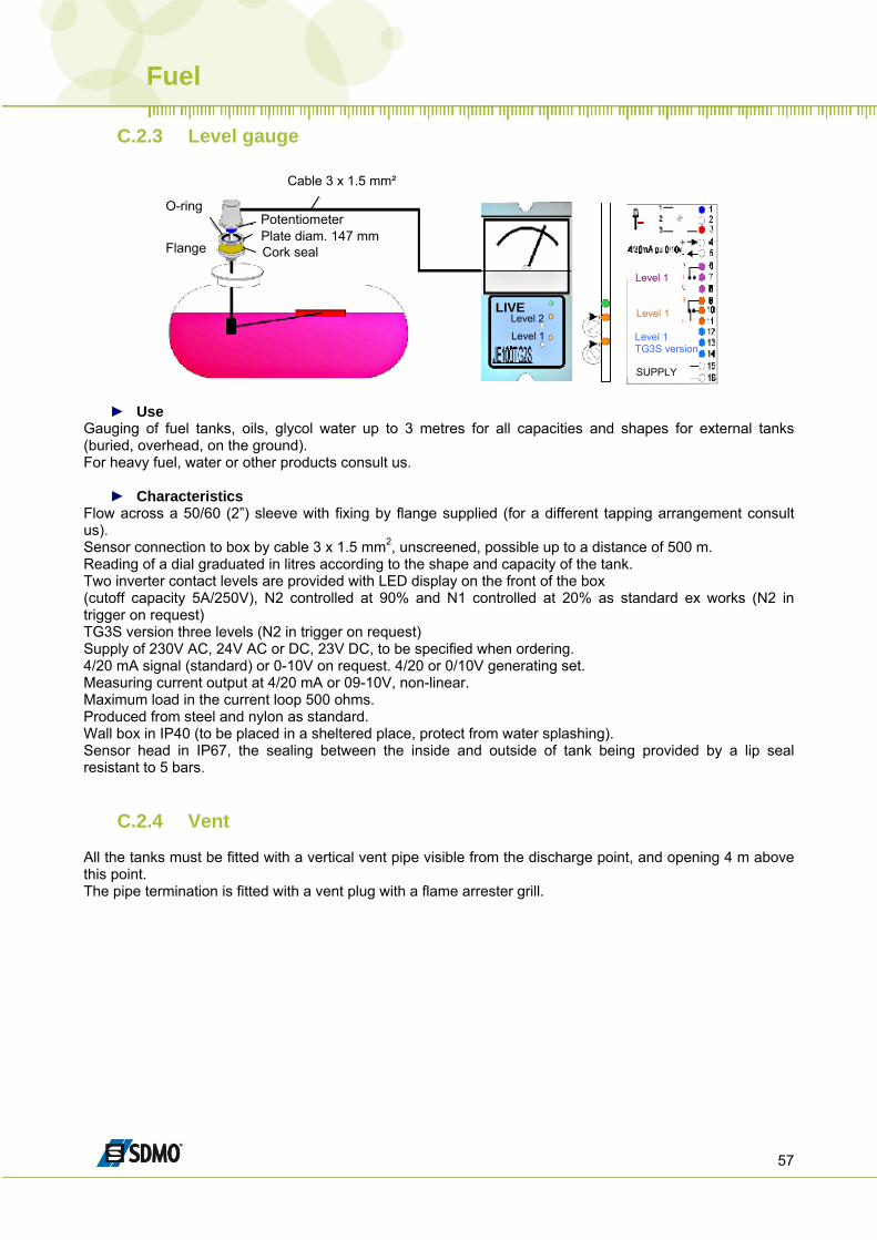
C.2.3 Level gauge
Cable 3 x 1.5 mm²
O-ring
Flange
Potentiometer Plate diam. 147 mm Cork seal
LIVELevel 2
Level 1
Level 1
Level 1
Level 1 TG3S version
SUPPLY
► Use
Gauging of fuel tanks, oils, glycol water up to 3 metres for all capacities and shapes for external tanks (buried, overhead, on the ground). For heavy fuel, water or other products consult us.
► Characteristics Flow across a 50/60 (2”) sleeve with fixing by flange supplied (for a different tapping arrangement consult us). Sensor connection to box by cable 3 x 1.5 mm2, unscreened, possible up to a distance of 500 m. Reading of a dial graduated in litres according to the shape and capacity of the tank. Two inverter contact levels are provided with LED display on the front of the box (cutoff capacity 5A/250V), N2 controlled at 90% and N1 controlled at 20% as standard ex works (N2 in trigger on request) TG3S version three levels (N2 in trigger on request) Supply of 230V AC, 24V AC or DC, 23V DC, to be specified when ordering. 4/20 mA signal (standard) or 0-10V on request. 4/20 or 0/10V generating set. Measuring current output at 4/20 mA or 09-10V, non-linear. Maximum load in the current loop 500 ohms. Produced from steel and nylon as standard. Wall box in IP40 (to be placed in a sheltered place, protect from water splashing). Sensor head in IP67, the sealing between the inside and outside of tank being provided by a lip seal resistant to 5 bars.
C.2.4 Vent All the tanks must be fitted with a vertical vent pipe visible from the discharge point, and opening 4 m above this point. The pipe termination is fitted with a vent plug with a flame arrester grill.
Fuel
58
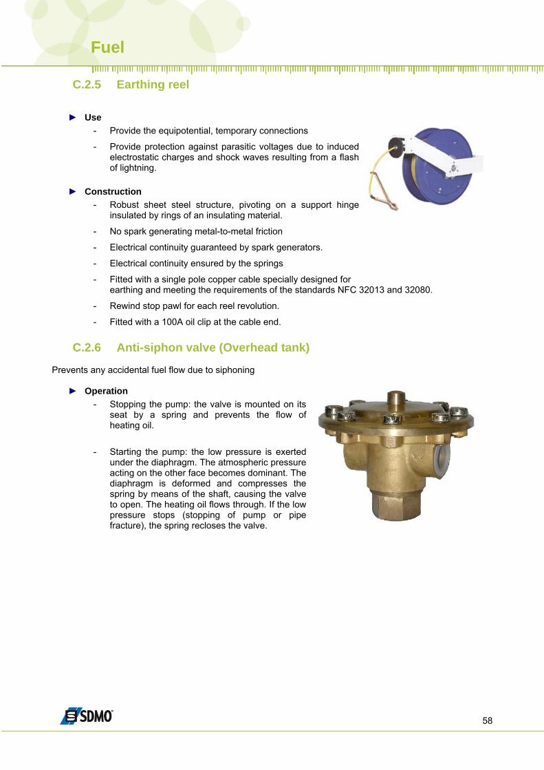
C.2.5 Earthing reel
► Use - Provide the equipotential, temporary connections
- Provide protection against parasitic voltages due to induced electrostatic charges and shock waves resulting from a flash of lightning.
► Construction
- Robust sheet steel structure, pivoting on a support hinge insulated by rings of an insulating material.
- No spark generating metal-to-metal friction
- Electrical continuity guaranteed by spark generators.
- Electrical continuity ensured by the springs
- Fitted with a single pole copper cable specially designed for earthing and meeting the requirements of the standards NFC 32013 and 32080.
- Rewind stop pawl for each reel revolution.
- Fitted with a 100A oil clip at the cable end.
C.2.6 Anti-siphon valve (Overhead tank) Prevents any accidental fuel flow due to siphoning
► Operation - Stopping the pump: the valve is mounted on its
seat by a spring and prevents the flow of heating oil.
- Starting the pump: the low pressure is exerted
under the diaphragm. The atmospheric pressure acting on the other face becomes dominant. The diaphragm is deformed and compresses the spring by means of the shaft, causing the valve to open. The heating oil flows through. If the low pressure stops (stopping of pump or pipe fracture), the spring recloses the valve.
Fuel
59
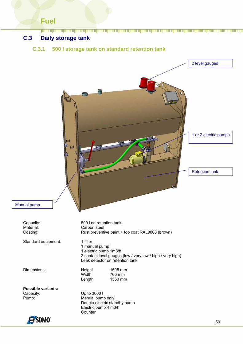
C.3 Daily storage tank
C.3.1 500 l storage tank on standard retention tank
2 level gauges
1 or 2 electric pumps
Retention tank
Manual pump
Capacity: 500 l on retention tank Material: Carbon steel Coating: Rust preventive paint + top coat RAL8008 (brown) Standard equipment: 1 filter 1 manual pump 1 electric pump 1m3/h 2 contact level gauges (low / very low / high / very high) Leak detector on retention tank Dimensions: Height 1505 mm Width 700 mm Length 1550 mm Possible variants: Capacity: Up to 3000 l Pump: Manual pump only Double electric standby pump Electric pump 4 m3/h Counter
Fuel
60
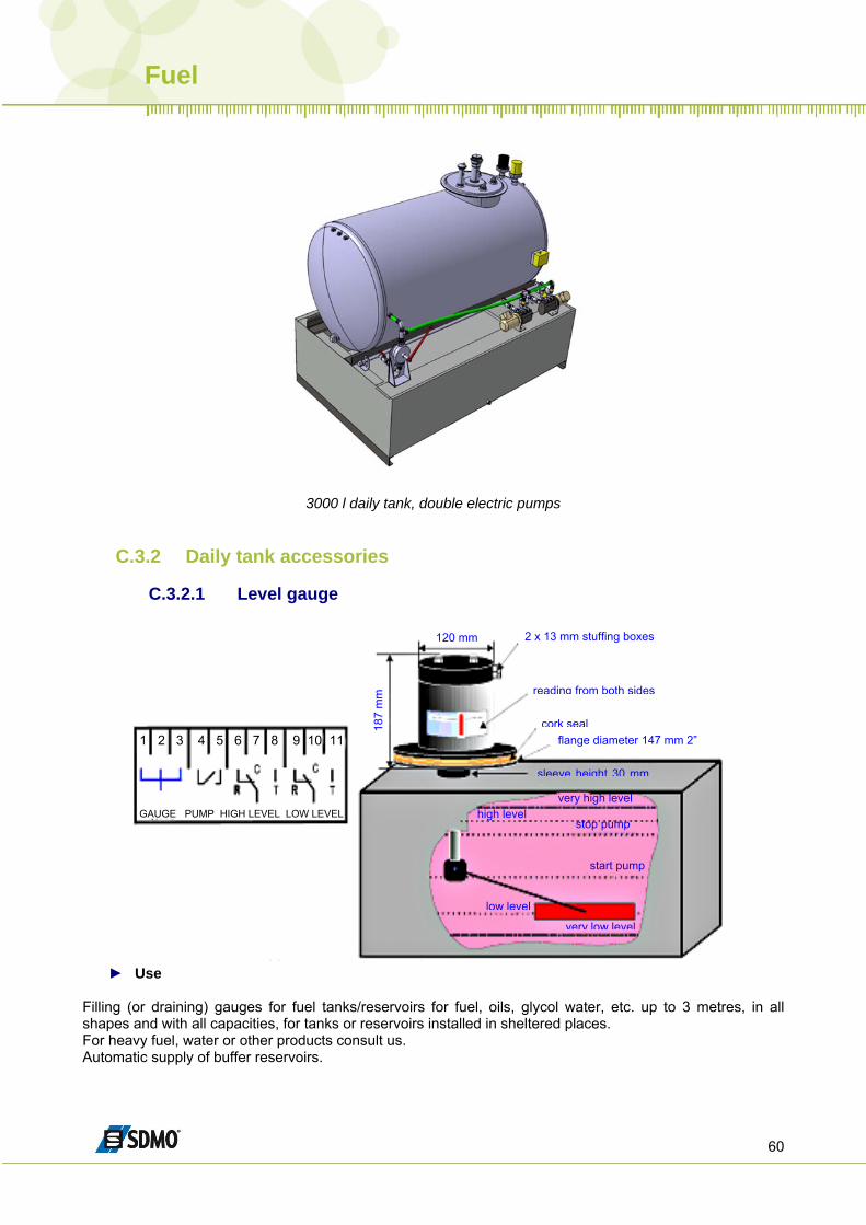
3000 l daily tank, double electric pumps
C.3.2 Daily tank accessories
C.3.2.1 Level gauge
1 2 3 4 5 6 7 8 9 10 11
GAUGE PUMP HIGH LEVEL LOW LEVEL
187
mm
120 mm
flange diameter 147 mm 2”
sleeve height 30 mm
high level stop pump
start pump
low level
very low level
very high level
2 x 13 mm stuffing boxes
reading from both sides
cork seal
► Use
Filling (or draining) gauges for fuel tanks/reservoirs for fuel, oils, glycol water, etc. up to 3 metres, in all shapes and with all capacities, for tanks or reservoirs installed in sheltered places. For heavy fuel, water or other products consult us. Automatic supply of buffer reservoirs.
Fuel
61
► Characteristics
Dry contacts, inverters, potential-free, cutoff capacity 4A under 50V AC Start/stop of filling (or drain) pump, high and low level contacts (possibility of 1 additional contact for very high or very low level). Direct reading on an amply dimensioned dial graduated in litres, other graduations available on request. Mounting on 50/60 (2”) sleeve as standard using a flange supplied with the unit (other fixing dimensions are available on request). It is connected as standard to a 96x96 receiver (NE 96/1) graduated in litres or percentage, according to the shape of the tank. IP54 sensor head; a tropicalised version is available. The sealing between the inside and the outside of the tank is provided by an O-ring resistant to 5 bars. Unit designed to measure the entire height of the tank. Very robust, IP54 tight, reliable.
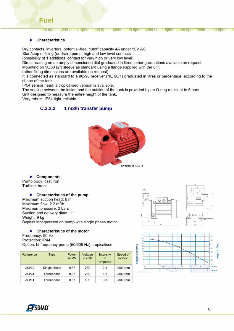
C.3.2.2 1 m3/h transfer pump
► Components Pump body: cast iron Turbine: brass
► Characteristics of the pump Maximum suction head: 6 m Maximum flow: 2.2 m3/h Maximum pressure: 2 bars Suction and delivery diam.: 1” Weight: 9 kg Bypass incorporated on pump with single phase motor
► Characteristics of the motor
heig
ht in
feet
Frequency: 50 Hz Protection: IP44 Option: bi-frequency pump (50/609 Hz), tropicalised Reference Type Power
in kW Voltage in volts
Intensity in
amperes
Speed of rotation
JEV10 Single phase 0.37 230 2.4 2800 rpm
JEV11 Threephase 0.37 230 1.6 2800 rpm
JEV11 Threephase 0.37 400 0.8 2800 rpm
heig
ht in
met
res
Fuel
62
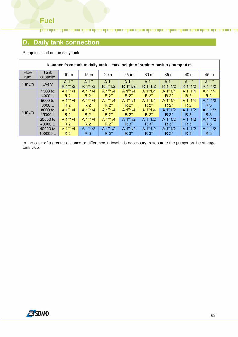
D. Daily tank connection Pump installed on the daily tank
Distance from tank to daily tank – max. height of strainer basket / pump: 4 m
Flow rate
Tank capacity 10 m 15 m 20 m 25 m 30 m 35 m 40 m 45 m
1 m3/h Every A 1 ‘’ R 1’’1/2
A 1 ‘’ R 1’’1/2
A 1 ‘’ R 1’’1/2
A 1 ‘’ R 1’’1/2
A 1 ‘’ R 1’’1/2
A 1 ‘’ R 1’’1/2
A 1 ‘’ R 1’’1/2
A 1 ‘’ R 1’’1/2
1500 to 4000 L
A 1’’1/4 R 2’’
A 1’’1/4 R 2’’
A 1’’1/4 R 2’’
A 1’’1/4 R 2’’
A 1’’1/4 R 2’’
A 1’’1/4 R 2’’
A 1’’1/4 R 2’’
A 1’’1/4 R 2’’
5000 to 6000 L
A 1’’1/4 R 2’’
A 1’’1/4 R 2’’
A 1’’1/4 R 2’’
A 1’’1/4 R 2’’
A 1’’1/4 R 2’’
A 1’’1/4 R 2’’
A 1’’1/4 R 2’’
A 1’’1/2 R 3’’
8000 to 15000 L
A 1’’1/4 R 2’’
A 1’’1/4 R 2’’
A 1’’1/4 R 2’’
A 1’’1/4 R 2’’
A 1’’1/4 R 2’’
A 1’’1/2 R 3’’
A 1’’1/2 R 3’’
A 1’’1/2 R 3’’
20000 to 40000 L
A 1’’1/4 R 2’’
A 1’’1/4 R 2’’
A 1’’1/4 R 2’’
A 1’’1/2 R 3’’
A 1’’1/2 R 3’’
A 1’’1/2 R 3’’
A 1’’1/2 R 3’’
A 1’’1/2 R 3’’
4 m3/h
40000 to 100000 L
A 1’’1/4 R 2’’
A 1’’1/2 R 3’’
A 1’’1/2 R 3’’
A 1’’1/2 R 3’’
A 1’’1/2 R 3’’
A 1’’1/2 R 3’’
A 1’’1/2 R 3’’
A 1’’1/2 R 3’’
In the case of a greater distance or difference in level it is necessary to separate the pumps on the storage tank side.
How to install a generating set ?
63
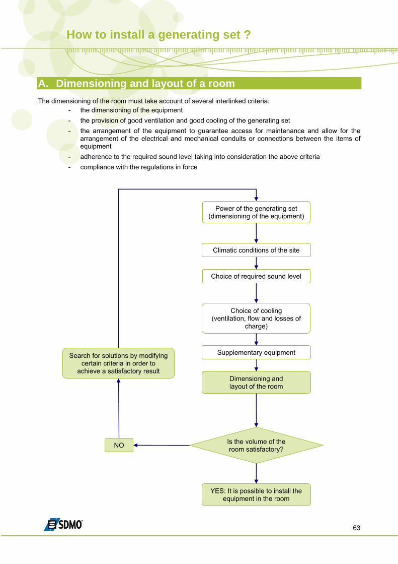
A. Dimensioning and layout of a room The dimensioning of the room must take account of several interlinked criteria:
- the dimensioning of the equipment - the provision of good ventilation and good cooling of the generating set - the arrangement of the equipment to guarantee access for maintenance and allow for the
arrangement of the electrical and mechanical conduits or connections between the items of equipment
- adherence to the required sound level taking into consideration the above criteria - compliance with the regulations in force
Power of the generating set (dimensioning of the equipment)
Climatic conditions of the site
Choice of required sound level
Choice of cooling (ventilation, flow and losses of
charge)
Search for solutions by modifying certain criteria in order to
achieve a satisfactory result Dimensioning and layout of the room
Is the volume of the room satisfactory? NO
Supplementary equipment
YES: It is possible to install the equipment in the room
How to install a generating set ?
64
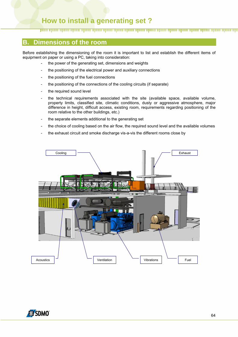
B. Dimensions of the room Before establishing the dimensioning of the room it is important to list and establish the different items of equipment on paper or using a PC, taking into consideration:
- the power of the generating set, dimensions and weights
- the positioning of the electrical power and auxiliary connections
- the positioning of the fuel connections
- the positioning of the connections of the cooling circuits (if separate)
- the required sound level
- the technical requirements associated with the site (available space, available volume, property limits, classified site, climatic conditions, dusty or aggressive atmosphere, major difference in height, difficult access, existing room, requirements regarding positioning of the room relative to the other buildings, etc.)
- the separate elements additional to the generating set
- the choice of cooling based on the air flow, the required sound level and the available volumes
- the exhaust circuit and smoke discharge vis-a-vis the different rooms close by
VentilationAcoustics
Cooling Exhaust
FuelVibrations
How to install a generating set ?
65
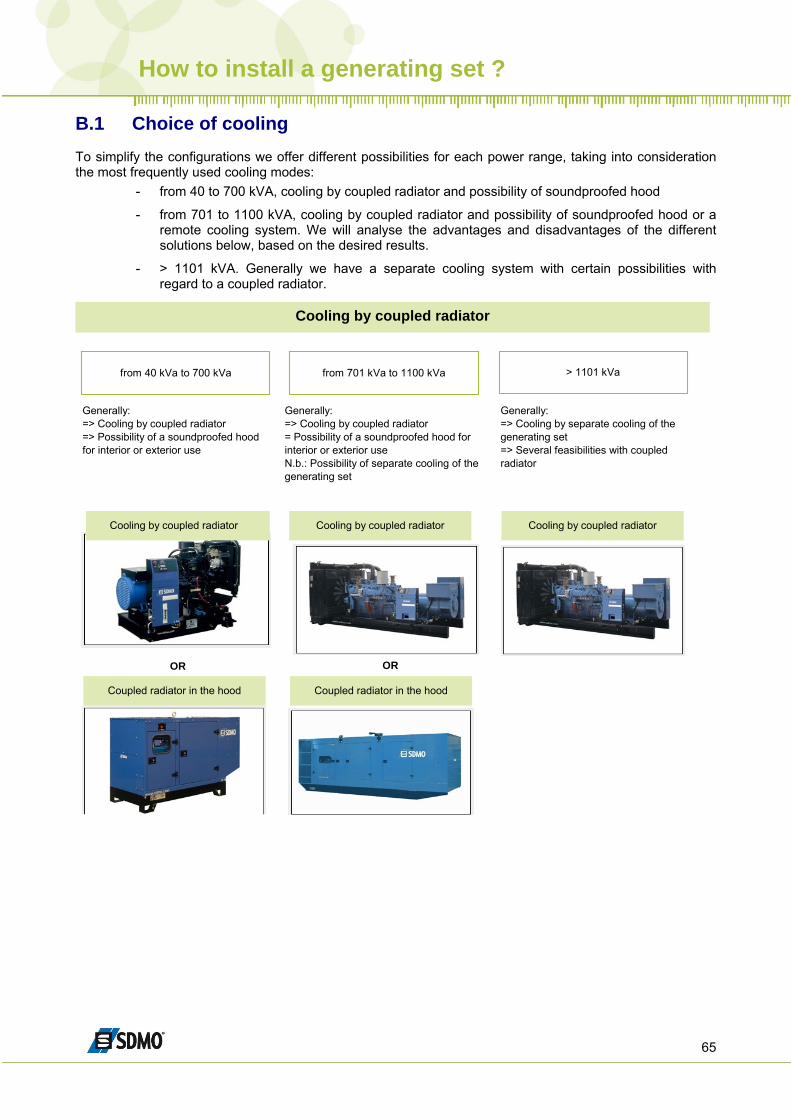
B.1 Choice of cooling To simplify the configurations we offer different possibilities for each power range, taking into consideration the most frequently used cooling modes:
- from 40 to 700 kVA, cooling by coupled radiator and possibility of soundproofed hood
- from 701 to 1100 kVA, cooling by coupled radiator and possibility of soundproofed hood or a remote cooling system. We will analyse the advantages and disadvantages of the different solutions below, based on the desired results.
- > 1101 kVA. Generally we have a separate cooling system with certain possibilities with regard to a coupled radiator.
Cooling by coupled radiator
from 40 kVa to 700 kVa from 701 kVa to 1100 kVa > 1101 kVa
Generally:=> Cooling by coupled radiator=> Possibility of a soundproofed hood for interior or exterior use
Generally:=> Cooling by coupled radiator= Possibility of a soundproofed hood for interior or exterior useN.b.: Possibility of separate cooling of the generating set
Generally:=> Cooling by separate cooling of the generating set=> Several feasibilities with coupled radiator
Cooling by coupled radiator� Cooling by coupled radiator Cooling by coupled radiator
Coupled radiator in the hood Coupled radiator in the hood
OR OR
How to install a generating set ?
66
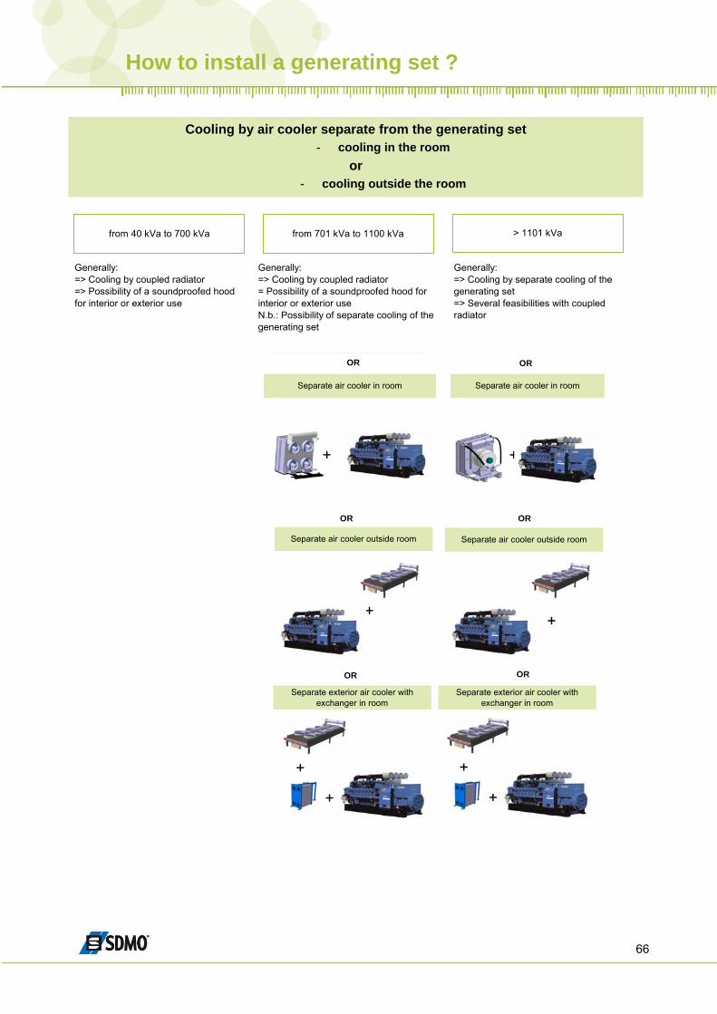
- cooling outside the room
- cooling in the room or
Cooling by air cooler separate from the generating set
> 1101 kVafrom 40 kVa to 700 kVa from 701 kVa to 1100 kVa
Generally:=> Cooling by coupled radiator=> Possibility of a soundproofed hood for interior or exterior use
Generally:=> Cooling by coupled radiator= Possibility of a soundproofed hood for interior or exterior useN.b.: Possibility of separate cooling of the generating set
Generally:=> Cooling by separate cooling of the generating set=> Several feasibilities with coupled radiator
+
+ +
Separate air cooler in roomSeparate air cooler in room
Separate air cooler outside roomSeparate air cooler outside room
OROR
OR OR
+
OR
Separate exterior air cooler with exchanger in room
Separate exterior air cooler with exchanger in room
+
+
OR
+
+
How to install a generating set ?
67
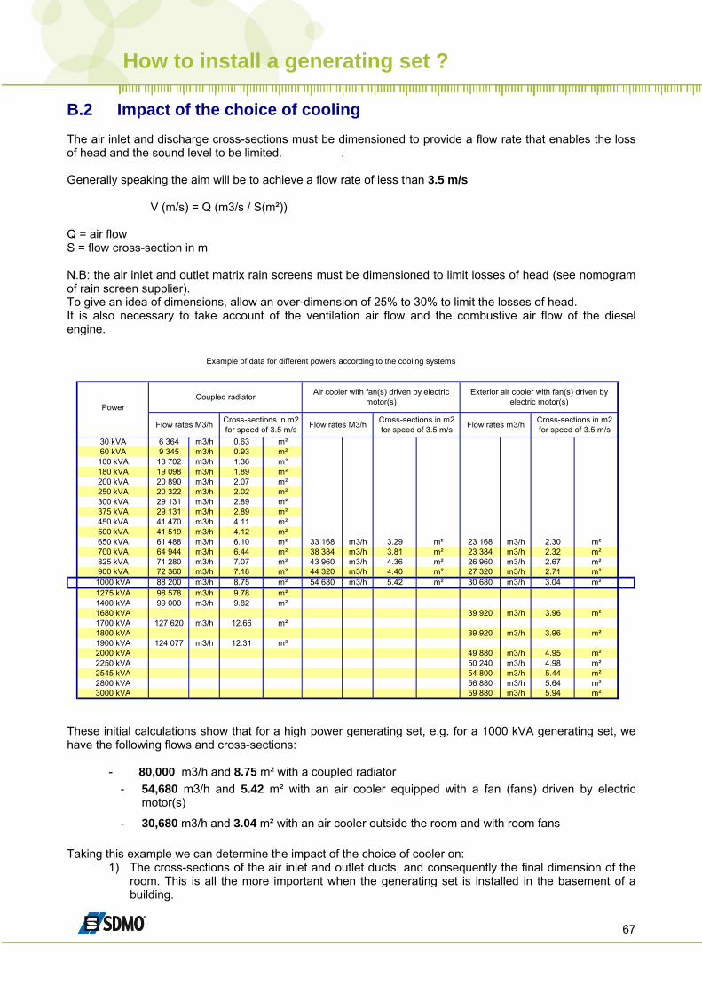
B.2 Impact of the choice of cooling The air inlet and discharge cross-sections must be dimensioned to provide a flow rate that enables the loss of head and the sound level to be limited. . Generally speaking the aim will be to achieve a flow rate of less than 3.5 m/s V (m/s) = Q (m3/s / S(m²)) Q = air flow S = flow cross-section in m N.B: the air inlet and outlet matrix rain screens must be dimensioned to limit losses of head (see nomogram of rain screen supplier). To give an idea of dimensions, allow an over-dimension of 25% to 30% to limit the losses of head. It is also necessary to take account of the ventilation air flow and the combustive air flow of the diesel engine.
Power
30 kVA 6 364 m3/h 0.63 m²60 kVA 9 345 m3/h 0.93 m²100 kVA 13 702 m3/h 1.36 m²180 kVA 19 098 m3/h 1.89 m²200 kVA 20 890 m3/h 2.07 m²250 kVA 20 322 m3/h 2.02 m²300 kVA 29 131 m3/h 2.89 m²375 kVA 29 131 m3/h 2.89 m²450 kVA 41 470 m3/h 4.11 m²500 kVA 41 519 m3/h 4.12 m²650 kVA 61 488 m3/h 6.10 m² 33 168 m3/h 3.29 m² 23 168 m3/h 2.30 m²700 kVA 64 944 m3/h 6.44 m² 38 384 m3/h 3.81 m² 23 384 m3/h 2.32 m²825 kVA 71 280 m3/h 7.07 m² 43 960 m3/h 4.36 m² 26 960 m3/h 2.67 m²900 kVA 72 360 m3/h 7.18 m² 44 320 m3/h 4.40 m² 27 320 m3/h 2.71 m²
1000 kVA 88 200 m3/h 8.75 m² 54 680 m3/h 5.42 m² 30 680 m3/h 3.04 m²1275 kVA 98 578 m3/h 9.78 m²1400 kVA 99 000 m3/h 9.82 m²1680 kVA 39 920 m3/h 3.96 m²1700 kVA 127 620 m3/h 12.66 m²1800 kVA 39 920 m3/h 3.96 m²1900 kVA 124 077 m3/h 12.31 m²2000 kVA 49 880 m3/h 4.95 m²2250 kVA 50 240 m3/h 4.98 m²2545 kVA 54 800 m3/h 5.44 m²2800 kVA 56 880 m3/h 5.64 m²3000 kVA 59 880 m3/h 5.94 m²
Flow rates m3/h Cross-sections in m2 for speed of 3.5 m/s
Exterior air cooler with fan(s) driven by electric motor(s)
Flow rates M3/h
Coupled radiator
Cross-sections in m2 for speed of 3.5 m/s
Air cooler with fan(s) driven by electric motor(s)
Flow rates M3/h Cross-sections in m2 for speed of 3.5 m/s
Example of data for different powers according to the cooling systems
These initial calculations show that for a high power generating set, e.g. for a 1000 kVA generating set, we have the following flows and cross-sections:
- 80,000 m3/h and 8.75 m² with a coupled radiator - 54,680 m3/h and 5.42 m² with an air cooler equipped with a fan (fans) driven by electric
motor(s)
- 30,680 m3/h and 3.04 m² with an air cooler outside the room and with room fans Taking this example we can determine the impact of the choice of cooler on:
1) The cross-sections of the air inlet and outlet ducts, and consequently the final dimension of the room. This is all the more important when the generating set is installed in the basement of a building.
How to install a generating set ?
68
2) It is also evident that we shall have better control of the exterior sound level with lower flows and cross-sections.
3) The dimensioning of the matrix rain screens at the air inlet and outlet 4) The dimensions, cross-sections and quantities of the series of resonators to be installed in the
ducts 5) Greater comfort for those working in the room during operation 6) The financial impact on the cross-sections and dimensions
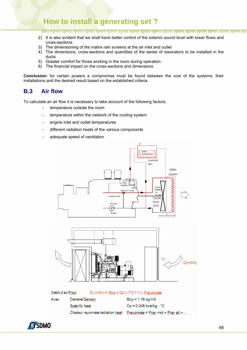
Conclusion: for certain powers a compromise must be found between the cost of the systems, their installations and the desired result based on the established criteria. B.3 Air flow To calculate an air flow it is necessary to take account of the following factors:
- temperature outside the room
- temperature within the network of the cooling system
- engine inlet and outlet temperatures
- different radiation heats of the various components
- adequate speed of ventilation
How to install a generating set ?
69
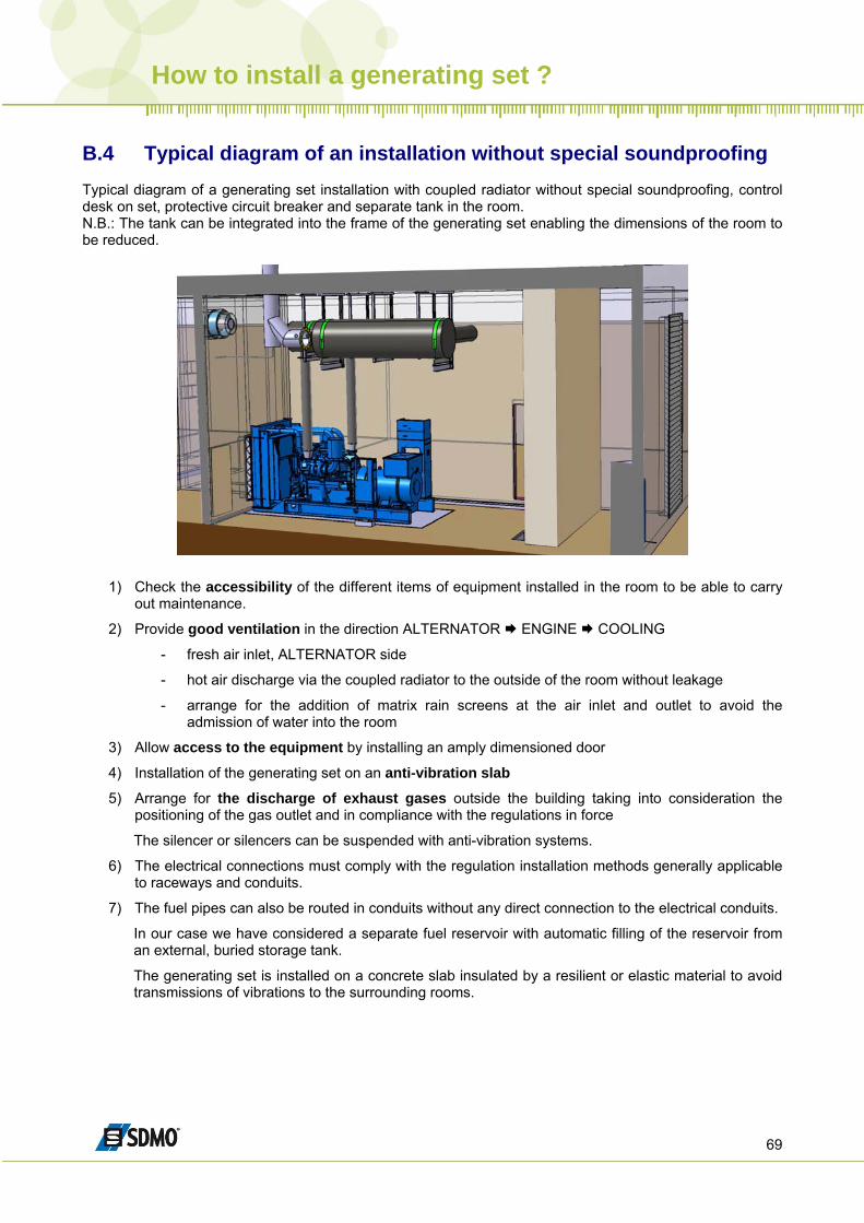
B.4 Typical diagram of an installation without special soundproofing Typical diagram of a generating set installation with coupled radiator without special soundproofing, control desk on set, protective circuit breaker and separate tank in the room. N.B.: The tank can be integrated into the frame of the generating set enabling the dimensions of the room to be reduced.
1) Check the accessibility of the different items of equipment installed in the room to be able to carry out maintenance.
2) Provide good ventilation in the direction ALTERNATOR ENGINE COOLING
- fresh air inlet, ALTERNATOR side
- hot air discharge via the coupled radiator to the outside of the room without leakage
- arrange for the addition of matrix rain screens at the air inlet and outlet to avoid the admission of water into the room
3) Allow access to the equipment by installing an amply dimensioned door
4) Installation of the generating set on an anti-vibration slab
5) Arrange for the discharge of exhaust gases outside the building taking into consideration the positioning of the gas outlet and in compliance with the regulations in force
The silencer or silencers can be suspended with anti-vibration systems.
6) The electrical connections must comply with the regulation installation methods generally applicable to raceways and conduits.
7) The fuel pipes can also be routed in conduits without any direct connection to the electrical conduits.
In our case we have considered a separate fuel reservoir with automatic filling of the reservoir from an external, buried storage tank.
The generating set is installed on a concrete slab insulated by a resilient or elastic material to avoid transmissions of vibrations to the surrounding rooms.
How to install a generating set ?
70
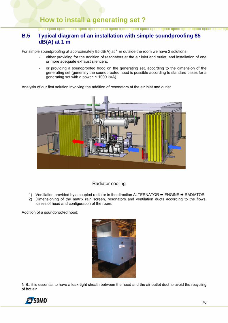
B.5 Typical diagram of an installation with simple soundproofing 85 dB(A) at 1 m
For simple soundproofing at approximately 85 dB(A) at 1 m outside the room we have 2 solutions:
- either providing for the addition of resonators at the air inlet and outlet, and installation of one or more adequate exhaust silencers.
- or providing a soundproofed hood on the generating set, according to the dimension of the generating set (generally the soundproofed hood is possible according to standard bases for a generating set with a power ≤ 1000 kVA).
Analysis of our first solution involving the addition of resonators at the air inlet and outlet
Radiator cooling
1) Ventilation provided by a coupled radiator in the direction ALTERNATOR ENGINE RADIATOR 2) Dimensioning of the matrix rain screen, resonators and ventilation ducts according to the flows,
losses of head and configuration of the room. Addition of a soundproofed hood:
N.B.: it is essential to have a leak-tight sheath between the hood and the air outlet duct to avoid the recycling of hot air
How to install a generating set ?
71
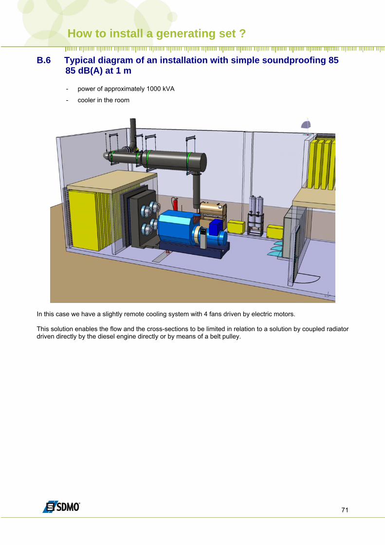
B.6 Typical diagram of an installation with simple soundproofing 85 85 dB(A) at 1 m
- power of approximately 1000 kVA
- cooler in the room
In this case we have a slightly remote cooling system with 4 fans driven by electric motors. This solution enables the flow and the cross-sections to be limited in relation to a solution by coupled radiator driven directly by the diesel engine directly or by means of a belt pulley.
How to install a generating set ?
72
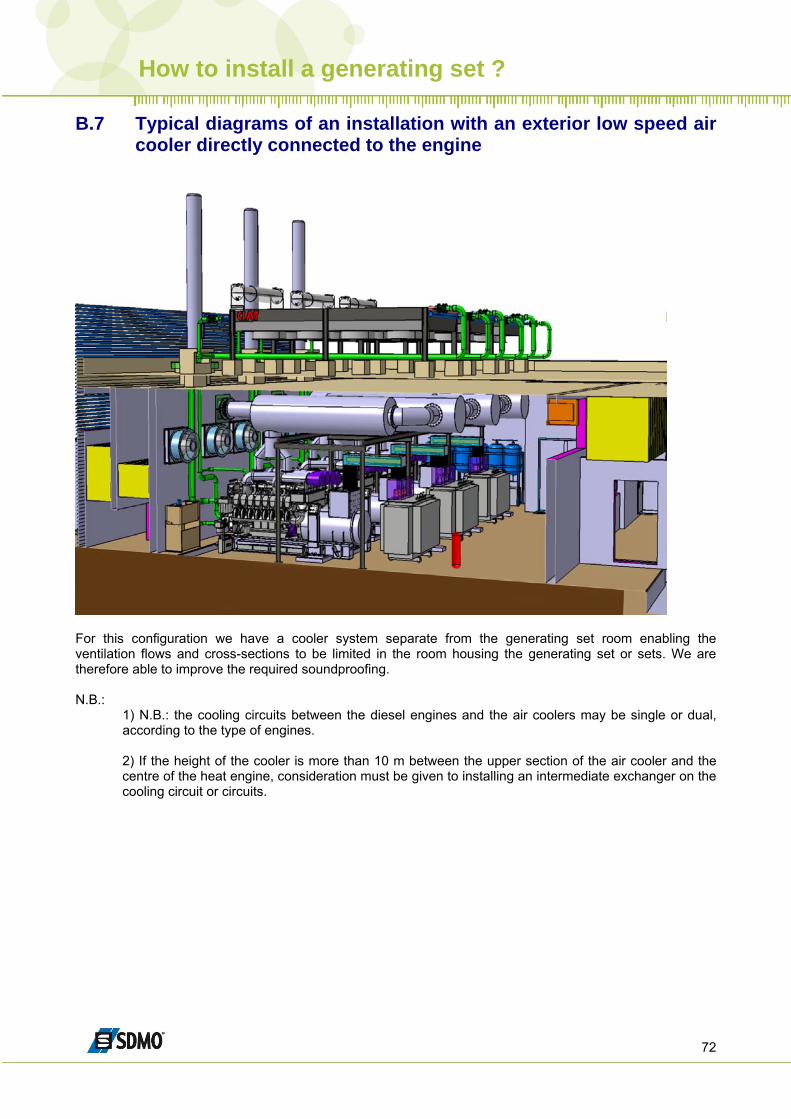
B.7 Typical diagrams of an installation with an exterior low speed air cooler directly connected to the engine
For this configuration we have a cooler system separate from the generating set room enabling the ventilation flows and cross-sections to be limited in the room housing the generating set or sets. We are therefore able to improve the required soundproofing. N.B.:
1) N.B.: the cooling circuits between the diesel engines and the air coolers may be single or dual, according to the type of engines. 2) If the height of the cooler is more than 10 m between the upper section of the air cooler and the centre of the heat engine, consideration must be given to installing an intermediate exchanger on the cooling circuit or circuits.
How to install a generating set ?
73
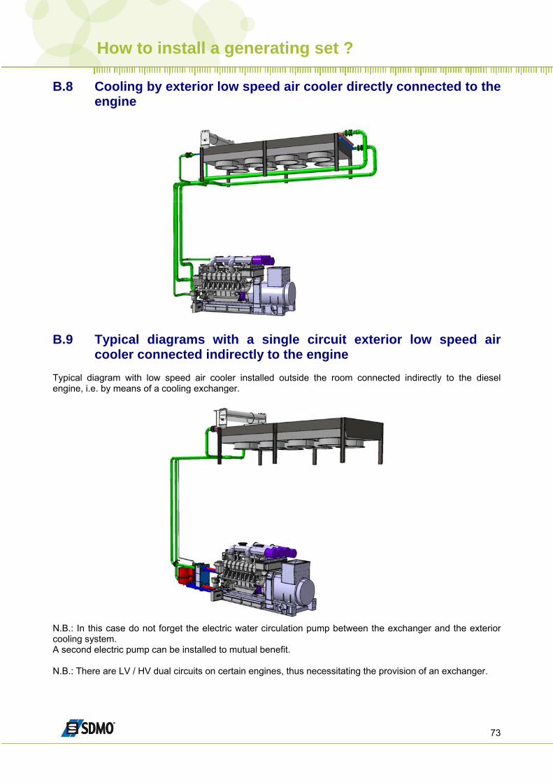
B.8 Cooling by exterior low speed air cooler directly connected to the engine
B.9 Typical diagrams with a single circuit exterior low speed air
cooler connected indirectly to the engine Typical diagram with low speed air cooler installed outside the room connected indirectly to the diesel engine, i.e. by means of a cooling exchanger.
N.B.: In this case do not forget the electric water circulation pump between the exchanger and the exterior cooling system. A second electric pump can be installed to mutual benefit. N.B.: There are LV / HV dual circuits on certain engines, thus necessitating the provision of an exchanger.
How to install a generating set ?
74
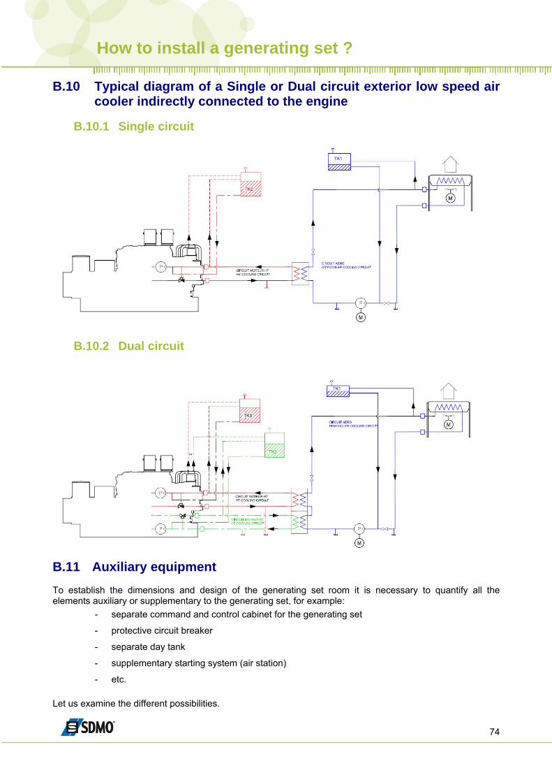
B.10 Typical diagram of a Single or Dual circuit exterior low speed air cooler indirectly connected to the engine
B.10.1 Single circuit
B.10.2 Dual circuit
B.11 Auxiliary equipment To establish the dimensions and design of the generating set room it is necessary to quantify all the elements auxiliary or supplementary to the generating set, for example:
- separate command and control cabinet for the generating set
- protective circuit breaker
- separate day tank
- supplementary starting system (air station)
- etc. Let us examine the different possibilities.
How to install a generating set ?
75
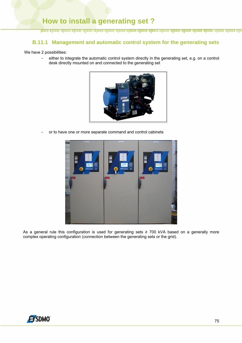
B.11.1 Management and automatic control system for the generating sets
We have 2 possibilities:
- either to integrate the automatic control system directly in the generating set, e.g. on a control desk directly mounted on and connected to the generating set
- or to have one or more separate command and control cabinets
As a general rule this configuration is used for generating sets ≥ 700 kVA based on a generally more complex operating configuration (connection between the generating sets or the grid).
How to install a generating set ?
76
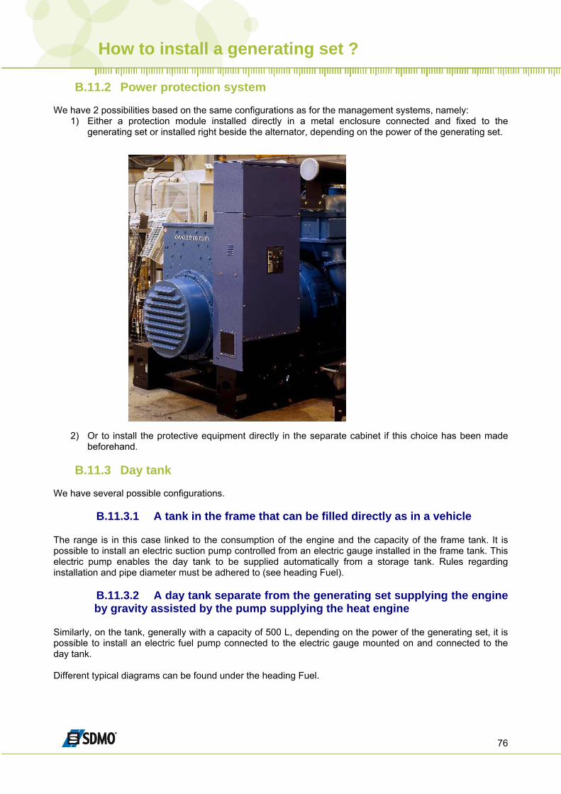
B.11.2 Power protection system We have 2 possibilities based on the same configurations as for the management systems, namely:
1) Either a protection module installed directly in a metal enclosure connected and fixed to the generating set or installed right beside the alternator, depending on the power of the generating set.
2) Or to install the protective equipment directly in the separate cabinet if this choice has been made beforehand.
B.11.3 Day tank
We have several possible configurations.
B.11.3.1 A tank in the frame that can be filled directly as in a vehicle The range is in this case linked to the consumption of the engine and the capacity of the frame tank. It is possible to install an electric suction pump controlled from an electric gauge installed in the frame tank. This electric pump enables the day tank to be supplied automatically from a storage tank. Rules regarding installation and pipe diameter must be adhered to (see heading Fuel).
B.11.3.2 A day tank separate from the generating set supplying the engine by gravity assisted by the pump supplying the heat engine
Similarly, on the tank, generally with a capacity of 500 L, depending on the power of the generating set, it is possible to install an electric fuel pump connected to the electric gauge mounted on and connected to the day tank. Different typical diagrams can be found under the heading Fuel.
How to install a generating set ?
77
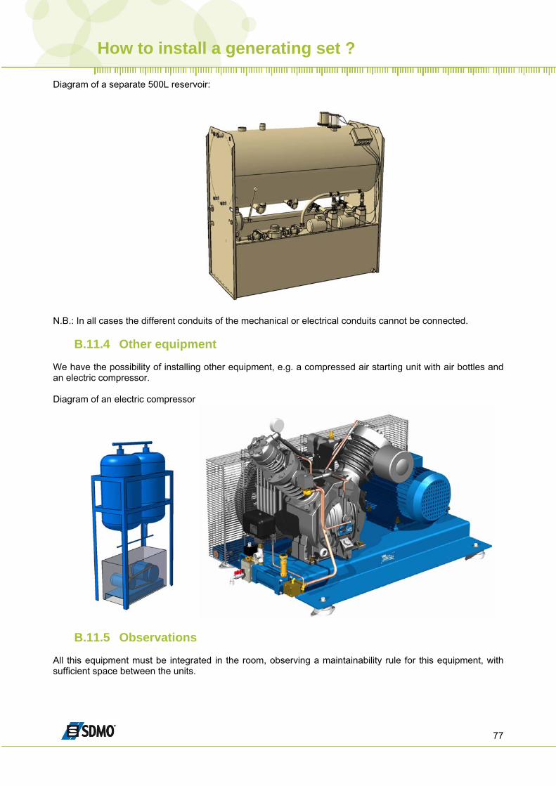
Diagram of a separate 500L reservoir:
N.B.: In all cases the different conduits of the mechanical or electrical conduits cannot be connected.
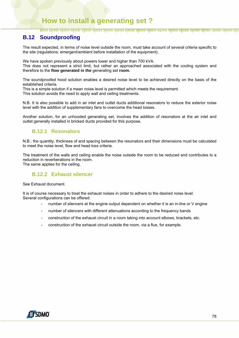
B.11.4 Other equipment We have the possibility of installing other equipment, e.g. a compressed air starting unit with air bottles and an electric compressor. Diagram of an electric compressor
B.11.5 Observations All this equipment must be integrated in the room, observing a maintainability rule for this equipment, with sufficient space between the units.
How to install a generating set ?
78
B.12 Soundproofing The result expected, in terms of noise level outside the room, must take account of several criteria specific to the site (regulations: emergent/ambient before installation of the equipment). We have spoken previously about powers lower and higher than 700 kVA. This does not represent a strict limit, but rather an approached associated with the cooling system and therefore to the flow generated in the generating set room. The soundproofed hood solution enables a desired noise level to be achieved directly on the basis of the established criteria. This is a simple solution if a mean noise level is permitted which meets the requirement. This solution avoids the need to apply wall and ceiling treatments. N.B. It is also possible to add in air inlet and outlet ducts additional resonators to reduce the exterior noise level with the addition of supplementary fans to overcome the head losses. Another solution, for an unhooded generating set, involves the addition of resonators at the air inlet and outlet generally installed in bricked ducts provided for this purpose.
B.12.1 Resonators N.B.: the quantity, thickness of and spacing between the resonators and their dimensions must be calculated to meet the noise level, flow and head loss criteria. The treatment of the walls and ceiling enable the noise outside the room to be reduced and contributes to a reduction in reverberations in the room. The same applies for the ceiling.
B.12.2 Exhaust silencer See Exhaust document. It is of course necessary to treat the exhaust noises in order to adhere to the desired noise level. Several configurations can be offered:
- number of silencers at the engine output dependent on whether it is an in-line or V engine
- number of silencers with different attenuations according to the frequency bands
- construction of the exhaust circuit in a room taking into account elbows, brackets, etc.
- construction of the exhaust circuit outside the room, via a flue, for example.