Embed Size (px)
DESCRIPTION
Technical Information Cabels
Citation preview
Photo: HELUKABEL�
Technical Information
�T
Technical Information
On the following pages your will find a summary withimportant details and instructions, which will enableyou to find information quickly and easily. You will finda detailed chapter of important standards, copper andalu-price calculation, core identifications, permissiblebending radius, dimensions, power ratings, comparisonof harmonized cables, strand make-up and conductorresistance, laying conditions for power cables, chemicalresistance of PUR, Silicone, Teflon and other thermo-plastic materials, characteristics of insulating andsheath materials, caloric load values of halogen-free orhalogenated cables, information and laying conditionsfor UL-CSA cables and wires, international abbreviations,formulas and practical facts etc.
It goes without saying that we can only mention afraction of all specifications as well as of the VDE-instructions. If you require the complete VDE specifica-tions, please ask the VDE-Publishing House in Berlin.
For any information please ask our Quality Assurancedepartment.
Any questions? HELUKABEL� will help you!
�
T
T
Contents and IndexSubject Page
T Technical Information
Copper and Alu-Price Calculation . . . . . . . . . . . . . . . . . . . . . . . . . . . . . . . . . . . . . . . . . . . . . . . . . . . . . . . . . . . . . . . . . . . . . . . . . . . . . . . . . . . . . . . . . . . . . . . . . . . . . . . . . . . . . . . . . . . . . . . . . . . . . T 1–T 2Reference to DIN VDE Standards . . . . . . . . . . . . . . . . . . . . . . . . . . . . . . . . . . . . . . . . . . . . . . . . . . . . . . . . . . . . . . . . . . . . . . . . . . . . . . . . . . . . . . . . . . . . . . . . . . . . . . . . . . . . . . . . . . . . . . . . . . . . . . T 3–T 4Harmonized Identification. . . . . . . . . . . . . . . . . . . . . . . . . . . . . . . . . . . . . . . . . . . . . . . . . . . . . . . . . . . . . . . . . . . . . . . . . . . . . . . . . . . . . . . . . . . . . . . . . . . . . . . . . . . . . . . . . . . . . . . . . . . . . . . . . . . . . . . . . . . . T 5Designation code for harmonized cables according to DIN VDE 0281/DIN VDE 0282/DIN VDE 0292. . . . . . . . . . . . . . . . . . . . . . . . . . . . . . . . . . . . . . . . . . . . . . . T 6Code-designation for harmonized cables and flexible cords to DIN VDE 0292 and HD 361 S2. . . . . . . . . . . . . . . . . . . . . . . . . . . . . . . . . . . . . . . . . . . . . . . . . T 7–T 8Comparison of harmonized cables with IEC, DIN VDE and HD . . . . . . . . . . . . . . . . . . . . . . . . . . . . . . . . . . . . . . . . . . . . . . . . . . . . . . . . . . . . . . . . . . . . . . . . . . . . . . . . . . . . . . . . . . . . . . . T 9Designation code for power cables according to DIN VDE 0271/0276 . . . . . . . . . . . . . . . . . . . . . . . . . . . . . . . . . . . . . . . . . . . . . . . . . . . . . . . . . . . . . . . . . . . . . . . . . . . . . . . . . . . . T 10Designation code for telephone cables, jumper wires and stranded hook-up wires . . . . . . . . . . . . . . . . . . . . . . . . . . . . . . . . . . . . . . . . . . . . . . . . . . . . . . . . . . . . . . . . . . . T 11Code-designation-explanations for cables and insulated wire . . . . . . . . . . . . . . . . . . . . . . . . . . . . . . . . . . . . . . . . . . . . . . . . . . . . . . . . . . . . . . . . . . . . . . . . . . . . . . . . . . . . . . . . . . . . . . . T 12Conductor-diameters according to DIN VDE 0295. . . . . . . . . . . . . . . . . . . . . . . . . . . . . . . . . . . . . . . . . . . . . . . . . . . . . . . . . . . . . . . . . . . . . . . . . . . . . . . . . . . . . . . . . . . . . . . . . . . . . . . . . . . . . . T 13Conductor resistance (extracted from DIN VDE 0295, IEC 228 and HD 383) . . . . . . . . . . . . . . . . . . . . . . . . . . . . . . . . . . . . . . . . . . . . . . . . . . . . . . . . . . . . . . . . . . . . . . . . . . . . . . T 14Strand make-up to (DIN VDE 0295, IEC 228 and HD 383). . . . . . . . . . . . . . . . . . . . . . . . . . . . . . . . . . . . . . . . . . . . . . . . . . . . . . . . . . . . . . . . . . . . . . . . . . . . . . . . . . . . . . . . . . . . . . . . . . . . . T 15Nominal voltage and Operating voltage. . . . . . . . . . . . . . . . . . . . . . . . . . . . . . . . . . . . . . . . . . . . . . . . . . . . . . . . . . . . . . . . . . . . . . . . . . . . . . . . . . . . . . . . . . . . . . . . . . . . . . . . . . . . . . . . . . . . . . . . . . T 16Current carrying capacity and indications for calculation of Power Cables and Wires. . . . . . . . . . . . . . . . . . . . . . . . . . . . . . . . . . . . . . . . . . . . . . . . . . . . . . . . . . . . . . . . . . T 17Type of Laying Systems and Operating Conditions – Power cables and wires for fixed installation – . . . . . . . . . . . . . . . . . . . . . . . . . . . . . . . . . . . . . . . . . . . . . . T 18Laying Conditions for Power Cables . . . . . . . . . . . . . . . . . . . . . . . . . . . . . . . . . . . . . . . . . . . . . . . . . . . . . . . . . . . . . . . . . . . . . . . . . . . . . . . . . . . . . . . . . . . . . . . . . . . . . . . . . . . . . . . . . . . . . . . . . . . . . . . T 19Current ratings for installation A1, A2, B1 and B2, Cables for fixed installation within buildings. . . . . . . . . . . . . . . . . . . . . . . . . . . . . . . . . . . . . . . . . . . . . . . . . . . . . T 20Current ratings for installation conditions C, E, F and G, Cables for fixed installation within buildings . . . . . . . . . . . . . . . . . . . . . . . . . . . . . . . . . . . . . . . . . . . . . T 21Current ratings for installation conditions A1, A2, B1 and B2, Cables for fixed installation within buildings . . . . . . . . . . . . . . . . . . . . . . . . . . . . . . . . . . . . . . T 22Current ratings for installation conditions C, E, F and G, Cables for fixed installation within buildings . . . . . . . . . . . . . . . . . . . . . . . . . . . . . . . . . . . . . . . . . . . . . T 23Current ratings for cables and insulated wires up to 1000 V and heat resistant cables . . . . . . . . . . . . . . . . . . . . . . . . . . . . . . . . . . . . . . . . . . . . . . . . . . . . . . . . . . . . . . T 24Current ratings for cables #0,6/1 kV, Special rubber-insulated single core cables, multicore rubber cables and trailing cables. . . . . . . . . . . . . T 25Current ratings (general) for flexible cables, for non-existing cable types in the previous tables . . . . . . . . . . . . . . . . . . . . . . . . . . . . . . . . . . . . . . . . . . . . . . . . . . . . T 26Current ratings for HELUTHERM 145 . . . . . . . . . . . . . . . . . . . . . . . . . . . . . . . . . . . . . . . . . . . . . . . . . . . . . . . . . . . . . . . . . . . . . . . . . . . . . . . . . . . . . . . . . . . . . . . . . . . . . . . . . . . . . . . . . . . . . . . . . . . . . . T 27Current ratings for silicone cables and wires . . . . . . . . . . . . . . . . . . . . . . . . . . . . . . . . . . . . . . . . . . . . . . . . . . . . . . . . . . . . . . . . . . . . . . . . . . . . . . . . . . . . . . . . . . . . . . . . . . . . . . . . . . . . . . . . . . . . T 28Current ratings for NYY, NAYY, NYCY, NYCWY, NAYCWY 0,6/1 kV . . . . . . . . . . . . . . . . . . . . . . . . . . . . . . . . . . . . . . . . . . . . . . . . . . . . . . . . . . . . . . . . . . . . . . . . . . . . . . . . . . . . . . . . . . . . . . T 29Current Carrying Capacity for NYKY 0,6/1 kV. . . . . . . . . . . . . . . . . . . . . . . . . . . . . . . . . . . . . . . . . . . . . . . . . . . . . . . . . . . . . . . . . . . . . . . . . . . . . . . . . . . . . . . . . . . . . . . . . . . . . . . . . . . . . . . . . . . . . T 30Current ratings – Conversion factors for grouping on the wall, on the floor, in insulation tubes or in conduit and under the ceiling. . . . . T 31Current ratings – Conversion factors for deviating ambient temperature . . . . . . . . . . . . . . . . . . . . . . . . . . . . . . . . . . . . . . . . . . . . . . . . . . . . . . . . . . . . . . . . . . . . . . . . . . . . . . . . T 32Current ratings – Conversion factors for grouping of single core cables or cables on troughs and trays . . . . . . . . . . . . . . . . . . . . . . . . . . . . . . . . . . . . . . . . T 33Current ratings – Conversion factors for grouping of multicore cables or cables on troughs and trays . . . . . . . . . . . . . . . . . . . . . . . . . . . . . . . . . . . . . . . . . . T 34Power ratings for XLPE-insulated; Medium Voltage Power Cables 6/10 kV, 12/20 kV, 18/30 kV . . . . . . . . . . . . . . . . . . . . . . . . . . . . . . . . . . . . . . . . . . . . . . . . . . . . . T 35Electrical characteristics of XLPE-insulated Medium Voltage Power Cables, 6–30 kV. . . . . . . . . . . . . . . . . . . . . . . . . . . . . . . . . . . . . . . . . . . . . . . . . . . . . . . . . . . . T 36–T 40Rating conversion factors for installation of Medium Voltage Cables, 6–30 kV. . . . . . . . . . . . . . . . . . . . . . . . . . . . . . . . . . . . . . . . . . . . . . . . . . . . . . . . . . . . . . . . . . . . . . . . . . . T 41Rating conversion factors for installation of Medium Voltage Cables, 6–30 kV. . . . . . . . . . . . . . . . . . . . . . . . . . . . . . . . . . . . . . . . . . . . . . . . . . . . . . . . . . . . . . . . . . . . . . . . . . . T 42Conversion factor for Medium Voltage Power Cables, 6–30 kV . . . . . . . . . . . . . . . . . . . . . . . . . . . . . . . . . . . . . . . . . . . . . . . . . . . . . . . . . . . . . . . . . . . . . . . . . . . . . . . . . . . . . . . . . . . . . . T 43Colour code according to DIN VDE 0293 . . . . . . . . . . . . . . . . . . . . . . . . . . . . . . . . . . . . . . . . . . . . . . . . . . . . . . . . . . . . . . . . . . . . . . . . . . . . . . . . . . . . . . . . . . . . . . . . . . . . . . . . . . . . . . . . . . . . . . . . . T 44Colour code according to E DIN VDE 0245 part 1 . . . . . . . . . . . . . . . . . . . . . . . . . . . . . . . . . . . . . . . . . . . . . . . . . . . . . . . . . . . . . . . . . . . . . . . . . . . . . . . . . . . . . . . . . . . . . . . . . . . . . . . . . . . . . . T 45Colour code according to DIN 47100 with colour repetition from core no. 45. and above . . . . . . . . . . . . . . . . . . . . . . . . . . . . . . . . . . . . . . . . . . . . . . . . . . . . . . . . . . . T 46Pair-Colour code according to DIN 47100 with colour repetition from pair no. 45 and above . . . . . . . . . . . . . . . . . . . . . . . . . . . . . . . . . . . . . . . . . . . . . . . . . . . . . . T 47Colour code HELUKABEL-JB. . . . . . . . . . . . . . . . . . . . . . . . . . . . . . . . . . . . . . . . . . . . . . . . . . . . . . . . . . . . . . . . . . . . . . . . . . . . . . . . . . . . . . . . . . . . . . . . . . . . . . . . . . . . . . . . . . . . . . . . . . . . . . . . . . . . . . . . . . T 48Colour code HELUKABEL-OB . . . . . . . . . . . . . . . . . . . . . . . . . . . . . . . . . . . . . . . . . . . . . . . . . . . . . . . . . . . . . . . . . . . . . . . . . . . . . . . . . . . . . . . . . . . . . . . . . . . . . . . . . . . . . . . . . . . . . . . . . . . . . . . . . . . . . . . . . T 49Colour code according to DIN VDE 0813 . . . . . . . . . . . . . . . . . . . . . . . . . . . . . . . . . . . . . . . . . . . . . . . . . . . . . . . . . . . . . . . . . . . . . . . . . . . . . . . . . . . . . . . . . . . . . . . . . . . . . . . . . . . . . . . . . . . . . . . . . T 50Colour code according to DIN VDE 0815 . . . . . . . . . . . . . . . . . . . . . . . . . . . . . . . . . . . . . . . . . . . . . . . . . . . . . . . . . . . . . . . . . . . . . . . . . . . . . . . . . . . . . . . . . . . . . . . . . . . . . . . . . . . . . . . . . . . . . . . . . T 51Colour code according to DIN VDE 0816 and extended. . . . . . . . . . . . . . . . . . . . . . . . . . . . . . . . . . . . . . . . . . . . . . . . . . . . . . . . . . . . . . . . . . . . . . . . . . . . . . . . . . . . . . . . . . . . . . . . . . . . . . . T 52Colour code for single wire vehicle cables . . . . . . . . . . . . . . . . . . . . . . . . . . . . . . . . . . . . . . . . . . . . . . . . . . . . . . . . . . . . . . . . . . . . . . . . . . . . . . . . . . . . . . . . . . . . . . . . . . . . . . . . . . . . . . . . . . . . . . . T 53Colour Abbreviations according to DIN VDE and IEC . . . . . . . . . . . . . . . . . . . . . . . . . . . . . . . . . . . . . . . . . . . . . . . . . . . . . . . . . . . . . . . . . . . . . . . . . . . . . . . . . . . . . . . . . . . . . . . . . . . . . . . . . . . T 54Identification of insulated wires through colours according to DIN 40705 and IEC 446 . . . . . . . . . . . . . . . . . . . . . . . . . . . . . . . . . . . . . . . . . . . . . . . . . . . . . . . . . . . . . . T 55Permissible minimum bending radius according to DIN VDE specifications . . . . . . . . . . . . . . . . . . . . . . . . . . . . . . . . . . . . . . . . . . . . . . . . . . . . . . . . . . . . . . . . . . . . . . . . . . . . . . T 56Chemical Resistance of PUR (Polyurethane) . . . . . . . . . . . . . . . . . . . . . . . . . . . . . . . . . . . . . . . . . . . . . . . . . . . . . . . . . . . . . . . . . . . . . . . . . . . . . . . . . . . . . . . . . . . . . . . . . . . . . . . . . . . . . . . . . . . . . . T 57Chemical Resistance of PUR – Table. . . . . . . . . . . . . . . . . . . . . . . . . . . . . . . . . . . . . . . . . . . . . . . . . . . . . . . . . . . . . . . . . . . . . . . . . . . . . . . . . . . . . . . . . . . . . . . . . . . . . . . . . . . . . . . . . . . . . . . T 58–T 59Chemical Resistance of HELUFLON� . . . . . . . . . . . . . . . . . . . . . . . . . . . . . . . . . . . . . . . . . . . . . . . . . . . . . . . . . . . . . . . . . . . . . . . . . . . . . . . . . . . . . . . . . . . . . . . . . . . . . . . . . . . . . . . . . . . . . . . . . . . . . . . . T 60Characteristics of HELUFLON�. . . . . . . . . . . . . . . . . . . . . . . . . . . . . . . . . . . . . . . . . . . . . . . . . . . . . . . . . . . . . . . . . . . . . . . . . . . . . . . . . . . . . . . . . . . . . . . . . . . . . . . . . . . . . . . . . . . . . . . . . . . . . . . . . . . . . . . . T 61Chemical Resistance of Silicone. . . . . . . . . . . . . . . . . . . . . . . . . . . . . . . . . . . . . . . . . . . . . . . . . . . . . . . . . . . . . . . . . . . . . . . . . . . . . . . . . . . . . . . . . . . . . . . . . . . . . . . . . . . . . . . . . . . . . . . . . . . . . . . . . . . . . T 62Resistance of substances against solvents, oils and fats . . . . . . . . . . . . . . . . . . . . . . . . . . . . . . . . . . . . . . . . . . . . . . . . . . . . . . . . . . . . . . . . . . . . . . . . . . . . . . . . . . . . . . . . . . . . . . . . . . . . . . T 62Heat-resistance classes as per VDE 0530 part 1 . . . . . . . . . . . . . . . . . . . . . . . . . . . . . . . . . . . . . . . . . . . . . . . . . . . . . . . . . . . . . . . . . . . . . . . . . . . . . . . . . . . . . . . . . . . . . . . . . . . . . . . . . . . . . . . . T 63Caloric load values (heat of combustion) . . . . . . . . . . . . . . . . . . . . . . . . . . . . . . . . . . . . . . . . . . . . . . . . . . . . . . . . . . . . . . . . . . . . . . . . . . . . . . . . . . . . . . . . . . . . . . . . . . . . . . . . . . . . . . . . . . . . . . . . . T 63Caloric load values of halogen-free Security Cables and insulated wires. . . . . . . . . . . . . . . . . . . . . . . . . . . . . . . . . . . . . . . . . . . . . . . . . . . . . . . . . . . . . . . . . . . . . . . . . . T 64–T 66Caloric load values of halogen-free Cables and insulated wires. . . . . . . . . . . . . . . . . . . . . . . . . . . . . . . . . . . . . . . . . . . . . . . . . . . . . . . . . . . . . . . . . . . . . . . . . . . . . . . . . . . . . . . . . . . . . T 67Caloric load values of halogen-free and haloganated cables and insulated wires . . . . . . . . . . . . . . . . . . . . . . . . . . . . . . . . . . . . . . . . . . . . . . . . . . . . . . . . . . . . . . T 68–T 70Information and Installation Instructions for UL and CSA cables . . . . . . . . . . . . . . . . . . . . . . . . . . . . . . . . . . . . . . . . . . . . . . . . . . . . . . . . . . . . . . . . . . . . . . . . . . . . . . . . . . . . . . . . . . . . T 71AWG-Wires and AWG-stranded conductors, Conductor make-up, cross-section, resistance and weight. . . . . . . . . . . . . . . . . . . . . . . . . . . . . . . . . . . . T 72–T 73US-American and British units, Conversion of usual measuring units/General measuring units . . . . . . . . . . . . . . . . . . . . . . . . . . . . . . . . . . . . . . . . . . . . . . . . . . . . . T 74Current ratings for UL-CSA cables. . . . . . . . . . . . . . . . . . . . . . . . . . . . . . . . . . . . . . . . . . . . . . . . . . . . . . . . . . . . . . . . . . . . . . . . . . . . . . . . . . . . . . . . . . . . . . . . . . . . . . . . . . . . . . . . . . . . . . . . . . . . . . . . . . T 75List of UL-Styles (Single core cables) . . . . . . . . . . . . . . . . . . . . . . . . . . . . . . . . . . . . . . . . . . . . . . . . . . . . . . . . . . . . . . . . . . . . . . . . . . . . . . . . . . . . . . . . . . . . . . . . . . . . . . . . . . . . . . . . . . . . . . . . . . . . . . . T 76List of UL-Styles (Multicore cables) . . . . . . . . . . . . . . . . . . . . . . . . . . . . . . . . . . . . . . . . . . . . . . . . . . . . . . . . . . . . . . . . . . . . . . . . . . . . . . . . . . . . . . . . . . . . . . . . . . . . . . . . . . . . . . . . . . . . . . . . . . . . . . . . . T 77Characteristics of insulating and sheath materials . . . . . . . . . . . . . . . . . . . . . . . . . . . . . . . . . . . . . . . . . . . . . . . . . . . . . . . . . . . . . . . . . . . . . . . . . . . . . . . . . . . . . . . . . . . . . . . . . . . . . T 78–T 79International abbreviations . . . . . . . . . . . . . . . . . . . . . . . . . . . . . . . . . . . . . . . . . . . . . . . . . . . . . . . . . . . . . . . . . . . . . . . . . . . . . . . . . . . . . . . . . . . . . . . . . . . . . . . . . . . . . . . . . . . . . . . . . . . . . . . . . . . . . . . . . . T 80Definitions: Classes of Stress (Duty) in Flexible Cables and Insulated Wires . . . . . . . . . . . . . . . . . . . . . . . . . . . . . . . . . . . . . . . . . . . . . . . . . . . . . . . . . . . . . . . . . . . . . . . . . . . . . . . T 81Safety Requirements in the Use of Cables and Insulated Wires . . . . . . . . . . . . . . . . . . . . . . . . . . . . . . . . . . . . . . . . . . . . . . . . . . . . . . . . . . . . . . . . . . . . . . . . . . . . . . . . . . . . . T 82–T 86Glossary of Terms: Cables and Wires. . . . . . . . . . . . . . . . . . . . . . . . . . . . . . . . . . . . . . . . . . . . . . . . . . . . . . . . . . . . . . . . . . . . . . . . . . . . . . . . . . . . . . . . . . . . . . . . . . . . . . . . . . . . . . . . . . . . . . . T 87–T 94International Certification Marks and Testing Institute . . . . . . . . . . . . . . . . . . . . . . . . . . . . . . . . . . . . . . . . . . . . . . . . . . . . . . . . . . . . . . . . . . . . . . . . . . . . . . . . . . . . . . . . . . . . . . . . . . . . . . . . T 95Formulas of electrotechnic and electronic . . . . . . . . . . . . . . . . . . . . . . . . . . . . . . . . . . . . . . . . . . . . . . . . . . . . . . . . . . . . . . . . . . . . . . . . . . . . . . . . . . . . . . . . . . . . . . . . . . . . . . . . . . . . . . . . . . . . . . . T 96Formulas of power engineering . . . . . . . . . . . . . . . . . . . . . . . . . . . . . . . . . . . . . . . . . . . . . . . . . . . . . . . . . . . . . . . . . . . . . . . . . . . . . . . . . . . . . . . . . . . . . . . . . . . . . . . . . . . . . . . . . . . . . . . . . . . . . . . . . . . . T 97Capacity of KTG-Pool drums . . . . . . . . . . . . . . . . . . . . . . . . . . . . . . . . . . . . . . . . . . . . . . . . . . . . . . . . . . . . . . . . . . . . . . . . . . . . . . . . . . . . . . . . . . . . . . . . . . . . . . . . . . . . . . . . . . . . . . . . . . . . . . . . . . . . . . . . . T 98Cable lengths (m) to KTG-Drums – capacity of pool drums . . . . . . . . . . . . . . . . . . . . . . . . . . . . . . . . . . . . . . . . . . . . . . . . . . . . . . . . . . . . . . . . . . . . . . . . . . . . . . . . . . . . . . . . . . . . . . . . . . T 99Explanatory notes on CE marking. . . . . . . . . . . . . . . . . . . . . . . . . . . . . . . . . . . . . . . . . . . . . . . . . . . . . . . . . . . . . . . . . . . . . . . . . . . . . . . . . . . . . . . . . . . . . . . . . . . . . . . . . . . . . . . . . . . . . . . T 100–T 101Part Number Index . . . . . . . . . . . . . . . . . . . . . . . . . . . . . . . . . . . . . . . . . . . . . . . . . . . . . . . . . . . . . . . . . . . . . . . . . . . . . . . . . . . . . . . . . . . . . . . . . . . . . . . . . . . . . . . . . . . . . . . . . . . . . . . . . . . . . . . . . T 102–T 112Table of types of cables and wires . . . . . . . . . . . . . . . . . . . . . . . . . . . . . . . . . . . . . . . . . . . . . . . . . . . . . . . . . . . . . . . . . . . . . . . . . . . . . . . . . . . . . . . . . . . . . . . . . . . . . . . . . . . . . . . . . . . . . . T 113–T 118
�T
R
Copper and Alu-Price Calculation
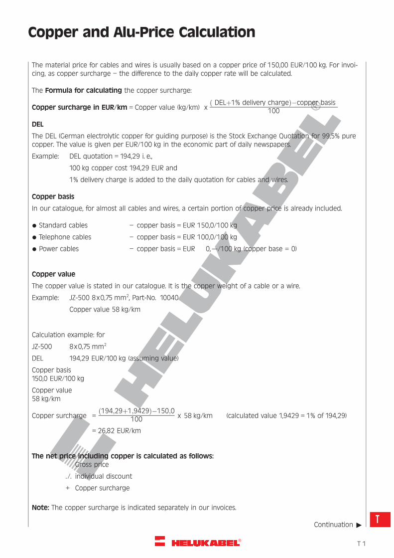
The material price for cables and wires is usually based on a copper price of 150,00 EUR/100 kg. For invoi-cing, as copper surcharge – the difference to the daily copper rate will be calculated.
The Formula for calculating the copper surcharge:
Copper surcharge in EUR/km = Copper value (kg/km) xð DELþ1% delivery chargeÞ�copper basis
100
DEL
The DEL (German electrolytic copper for guiding purpose) is the Stock Exchange Quotation for 99,5% purecopper. The value is given per EUR/100 kg in the economic part of daily newspapers.
Example: DEL quotation = 194,29 i. e.,
100 kg copper cost 194,29 EUR and
1% delivery charge is added to the daily quotation for cables and wires.
Copper basis
In our catalogue, for almost all cables and wires, a certain portion of copper price is already included.
* Standard cables – copper basis = EUR 150,0/100 kg
* Telephone cables – copper basis = EUR 100,0/100 kg
* Power cables – copper basis = EUR 0,–/100 kg (copper base = 0)
Copper value
The copper value is stated in our catalogue. It is the copper weight of a cable or a wire.
Example: JZ-500 8x0,75 mm2, Part-No. 10040
Copper value 58 kg/km
Calculation example: for
JZ-500 8x0,75 mm2
DEL 194,29 EUR/100 kg (assuming value)
Copper basis150,0 EUR/100 kg
Copper value58 kg/km
Copper surcharge =ð194;29þ1;9429Þ�150;0
100 x 58 kg/km (calculated value 1,9429 = 1% of 194,29)
= 26,82 EUR/km
The net price including copper is calculated as follows:Gross price
. /. individual discount
+ Copper surcharge
Note: The copper surcharge is indicated separately in our invoices.
Continuation "
�T 1
T
R
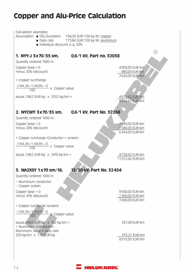
Copper and Alu-Price Calculation
Calculation examples:Assumption: * DEL-Quotation 194,29 EUR/100 kg for copper
* Daily rate 173,84 EUR/100 kg for aluminium* Individual discount, e. g. 20%
1. NYY-J 3x70/35 sm, 0,6/1 kV, Part no. 32038
Quantity ordered 1000 m
Copper base = 0 4900,00 EUR/kmminus 20% (discount) 980,00 EUR/km
3920,00 EUR/km
+ Copper surcharge:
ð194;29þ1;9429Þ�0100 x Copper value
equal, 1,962 EUR/kg x 2352 kg/km = 4614,62 EUR/km8534,62 EUR/km
2. NYCWY 3x70/35 sm, 0,6/1 kV, Part No. 32268
Quantity ordered 1000 m
Copper base = 0 7930,00 EUR/kmminus 20% (discount) 1586,00 EUR/km
6344,00 EUR/km
+ Copper surcharge (Conductor + screen):
ð194;29þ1;9429Þ�0100 x Copper value
equal, 1,962 EUR/kg x 2410 kg/km = 4728,42 EUR/km11072,42 EUR/km
3. NA2XSY 1x70 sm/16, 12/20 kV, Part No. 32454
Quantity ordered 1000 m
– Aluminium conductor
– Copper screen
Copper base = 0 9500,00 EUR/kmminus 20% (discount) 1900,00 EUR/km
7600,00 EUR/km
+ Copper surcharge (screen):
ð194;29þ1;9429Þ�0100 x Copper value
equal, 1,962 EUR/kg x 182 kg/km = 357,08 EUR/km
+ Aluminium (Conductor):Aluminium value x daily rate203 kg/km x 1,74 EUR/kg 353,22 EUR/km
8310,30 EUR/km
�T 2
R
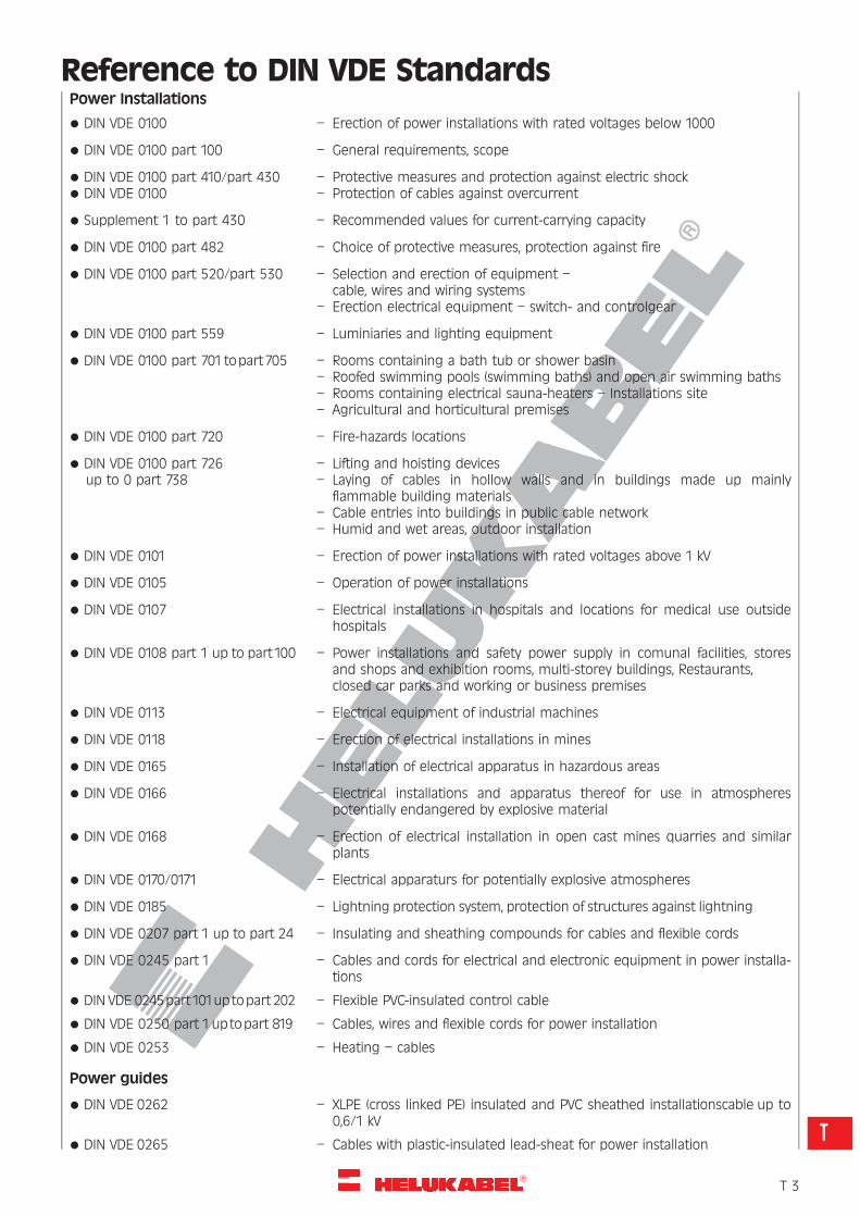
Reference to DIN VDE StandardsPower Installations
* DIN VDE 0100 – Erection of power installations with rated voltages below 1000
* DIN VDE 0100 part 100 – General requirements, scope
* DIN VDE 0100 part 410/part 430 – Protective measures and protection against electric shock* DIN VDE 0100 – Protection of cables against overcurrent
* Supplement 1 to part 430 – Recommended values for current-carrying capacity
* DIN VDE 0100 part 482 – Choice of protective measures, protection against fire
* DIN VDE 0100 part 520/part 530 – Selection and erection of equipment –cable, wires and wiring systems
– Erection electrical equipment – switch- and controlgear
* DIN VDE 0100 part 559 – Luminiaries and lighting equipment
* DIN VDE 0100 part 701topart705 – Rooms containing a bath tub or shower basin– Roofed swimming pools (swimming baths) and open air swimming baths– Rooms containing electrical sauna-heaters – Installations site– Agricultural and horticultural premises
* DIN VDE 0100 part 720 – Fire-hazards locations
* DIN VDE 0100 part 726 – Lifting and hoisting devicesup to 0 part 738 – Laying of cables in hollow walls and in buildings made up mainly
flammable building materials– Cable entries into buildings in public cable network– Humid and wet areas, outdoor installation
* DIN VDE 0101 – Erection of power installations with rated voltages above 1 kV
* DIN VDE 0105 – Operation of power installations
* DIN VDE 0107 – Electrical installations in hospitals and locations for medical use outsidehospitals
* DIN VDE 0108 part 1 up to part100 – Power installations and safety power supply in comunal facilities, storesand shops and exhibition rooms, multi-storey buildings, Restaurants,closed car parks and working or business premises
* DIN VDE 0113 – Electrical equipment of industrial machines
* DIN VDE 0118 – Erection of electrical installations in mines
* DIN VDE 0165 – Installation of electrical apparatus in hazardous areas
* DIN VDE 0166 – Electrical installations and apparatus thereof for use in atmospherespotentially endangered by explosive material
* DIN VDE 0168 – Erection of electrical installation in open cast mines quarries and similarplants
* DIN VDE 0170/0171 – Electrical apparaturs for potentially explosive atmospheres
* DIN VDE 0185 – Lightning protection system, protection of structures against lightning
* DIN VDE 0207 part 1 up to part 24 – Insulating and sheathing compounds for cables and flexible cords
* DIN VDE 0245 part 1 – Cables and cords for electrical and electronic equipment in power installa-tions
* DIN VDE 0245part101uptopart 202 – Flexible PVC-insulated control cable
* DIN VDE 0250 part 1uptopart 819 – Cables, wires and flexible cords for power installation
* DIN VDE 0253 – Heating – cables
Power guides
* DIN VDE 0262 – XLPE (cross linked PE) insulated and PVC sheathed installationscable up to0,6/1 kV
* DIN VDE 0265 – Cables with plastic-insulated lead-sheat for power installation
�T 3
T
R
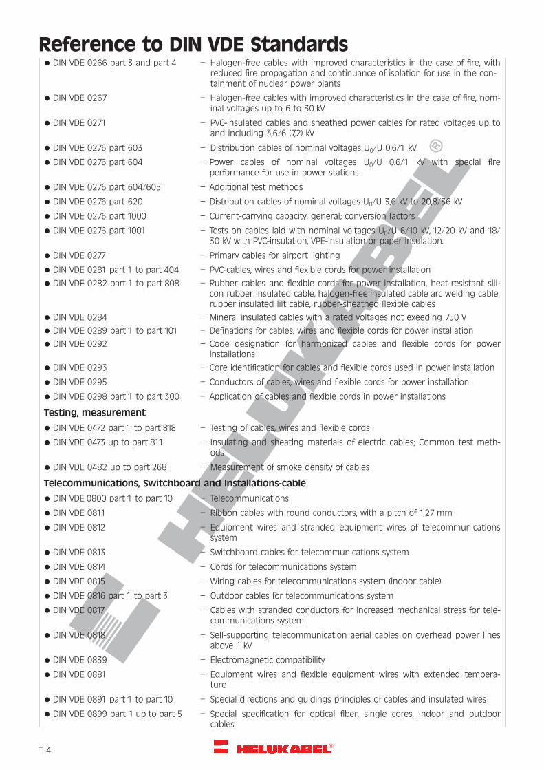
Reference to DIN VDE Standards* DIN VDE 0266 part 3 and part 4 – Halogen-free cables with improved characteristics in the case of fire, with
reduced fire propagation and continuance of isolation for use in the con-tainment of nuclear power plants
* DIN VDE 0267 – Halogen-free cables with improved characteristics in the case of fire, nom-inal voltages up to 6 to 30 kV
* DIN VDE 0271 – PVC-insulated cables and sheathed power cables for rated voltages up toand including 3,6/6 (7,2) kV
* DIN VDE 0276 part 603 – Distribution cables of nominal voltages U0/U 0,6/1 kV
* DIN VDE 0276 part 604 – Power cables of nominal voltages U0/U 0.6/1 kV with special fireperformance for use in power stations
* DIN VDE 0276 part 604/605 – Additional test methods
* DIN VDE 0276 part 620 – Distribution cables of nominal voltages U0/U 3,6 kV to 20,8/36 kV
* DIN VDE 0276 part 1000 – Current-carrying capacity, general; conversion factors
* DIN VDE 0276 part 1001 – Tests on cables laid with nominal voltages U0/U 6/10 kV, 12/20 kV and 18/30 kV with PVC-insulation, VPE-insulation or paper insulation.
* DIN VDE 0277 – Primary cables for airport lighting
* DIN VDE 0281 part 1 to part 404 – PVC-cables, wires and flexible cords for power installation
* DIN VDE 0282 part 1 to part 808 – Rubber cables and flexible cords for power installation, heat-resistant sili-con rubber insulated cable, halogen-free insulated cable arc welding cable,rubber insulated lift cable, rubber-sheathed flexible cables
* DIN VDE 0284 – Mineral insulated cables with a rated voltages not exeeding 750 V
* DIN VDE 0289 part 1 to part 101 – Definations for cables, wires and flexible cords for power installation
* DIN VDE 0292 – Code designation for harmonized cables and flexible cords for powerinstallations
* DIN VDE 0293 – Core identification for cables and flexible cords used in power installation
* DIN VDE 0295 – Conductors of cables, wires and flexible cords for power installation
* DIN VDE 0298 part 1 to part 300 – Application of cables and flexible cords in power installations
Testing, measurement
* DIN VDE 0472 part 1 to part 818 – Testing of cables, wires and flexible cords
* DIN VDE 0473 up to part 811 – Insulating and sheating materials of electric cables; Common test meth-ods
* DIN VDE 0482 up to part 268 – Measurement of smoke density of cables
Telecommunications, Switchboard and Installations-cable
* DIN VDE 0800 part 1 to part 10 – Telecommunications
* DIN VDE 0811 – Ribbon cables with round conductors, with a pitch of 1,27 mm
* DIN VDE 0812 – Equipment wires and stranded equipment wires of telecommunicationssystem
* DIN VDE 0813 – Switchboard cables for telecommunications system
* DIN VDE 0814 – Cords for telecommunications system
* DIN VDE 0815 – Wiring cables for telecommunications system (indoor cable)
* DIN VDE 0816 part 1 to part 3 – Outdoor cables for telecommunications system
* DIN VDE 0817 – Cables with stranded conductors for increased mechanical stress for tele-communications system
* DIN VDE 0818 – Self-supporting telecommunication aerial cables on overhead power linesabove 1 kV
* DIN VDE 0839 – Electromagnetic compatibility
* DIN VDE 0881 – Equipment wires and flexible equipment wires with extended tempera-ture
* DIN VDE 0891 part 1 to part 10 – Special directions and guidings principles of cables and insulated wires
* DIN VDE 0899 part 1 up to part 5 – Special specification for optical fiber, single cores, indoor and outdoorcables
�T 4
R
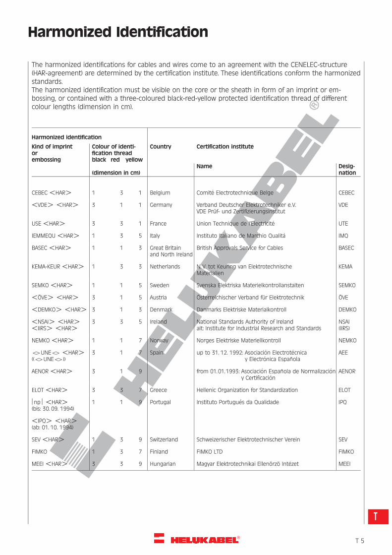
Harmonized Identification
The harmonized identifications for cables and wires come to an agreement with the CENELEC-structure(HAR-agreement) are determined by the certification institute. These identifications conform the harmonizedstandards.The harmonized identification must be visible on the core or the sheath in form of an imprint or em-bossing, or contained with a three-coloured black-red-yellow protected identification thread of differentcolour lengths (dimension in cm).
Harmonized identification
Kind of imprintorembossing
Colour of identi-fication threadblack red yellow
Country Certification institute
(dimension in cm)Name Desig-
nation
CEBEC5HAR4 1 3 1 Belgium Comite Electrotechnique Belge CEBEC
5VDE45HAR4 3 1 1 Germany Verband Deutscher Elektrotechniker e. V.VDE Pruf- und Zertifizierungsinstitut
VDE
USE5HAR4 3 3 1 France Union Technique de l’Electricite UTE
IEMMEQU5HAR4 1 3 5 Italy Instituto Italiano de Marchio Qualita IMQ
BASEC5HAR4 1 1 3 Great Britainand North Ireland
British Approvals Service for Cables BASEC
KEMA-KEUR5HAR4 1 3 3 Netherlands N. V. tot Keuring van ElektrotechnischeMaterialien
KEMA
SEMKO5HAR4 1 1 5 Sweden Svenska Elektriska Materielkontrollanstalten SEMKO
5OVE45HAR4 3 1 5 Austria Osterreichischer Verband fur Elektrotechnik OVE
5DEMKO45HAR4 3 1 3 Denmark Danmarks Elektriske Materialkontroll DEMKO
5NSAI45HAR45IIRS45HAR4
3 3 5 Ireland National Standards Authority of Irelandalt: Institute for Industrial Research and Standards
NSAI(IIRS)
NEMKO5HAR4 1 1 7 Norway Norges Elektriske Materiellkontroll NEMKO
54UNE545HAR4((54UNE54))
3 1 7 Spain up to 31. 12. 1992: Asociacion Electrotecnicay Electronica Espanola
AEE
AENOR5HAR4 3 1 9 from 01.01.1993: Asociacion Espanola de Normalizaciony Certificacion
AENOR
ELOT5HAR4 3 3 7 Greece Hellenic Organization for Standardization ELOT
‰np‰5HAR4(bis: 30. 09. 1994)
1 1 9 Portugal Instituto Portugues da Qualidade IPQ
5IPQ45HAR4(ab: 01. 10. 1994)
SEV5HAR4 1 3 9 Switzerland Schweizerischer Elektrotechnischer Verein SEV
FIMKO 1 3 7 Finland FIMKO LTD FIMKO
MEEI5HAR4 3 3 9 Hungarian Magyar Elektrotechnikai Ellenorzo Intezet MEEI
�T 5
T
R
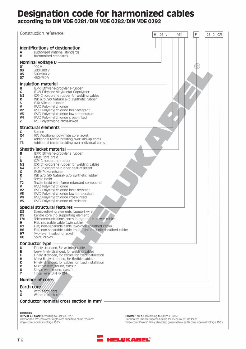
Designation code for harmonized cablesaccording to DIN VDE 0281/DIN VDE 0282/DIN VDE 0292
Construction reference H 05 V V5 – F 25 G 0,75
Identifications of destignationA authorised national standardsH harmonized standards
Nominal voltage U01 100 V03 300/300 V05 300/500 V07 450/750 V
Insulation materialB (EPR) Ethylene-propylene-rubberG (EVA) Ethylene-Vinylacetat-CopolymerN2 (CR) Chloroprene rubber for welding cablesR (NR a./o. SR) Natural a./o. synthetic rubberS (SiR) Silicone rubberV (PVC) Polyvinyl chlorideV2 (PVC) Polyvinyl chloride heat-resistantV3 (PVC) Polyvinyl chloride low-temperatureV4 (PVC) Polyvinyl chloride cross-linkedZ (PE) Polyethylene cross-linked
Structural elementsC ScreenQ4 (PA) Additional polyimide core jacketT Additional textile braiding over laid-up coresT6 Additional textile braiding over individual cores
Sheath/jacket materialB (EPR) Ethylene-propylene rubberJ Glass fibre braidN (CR) Chloroprene rubberN2 (CR) Chloroprene rubber for welding cablesN4 (CR) Chloroprene rubber heat-resistantQ (PUR) PolyurethaneR (NR a./o. SR) Natural- a./o. synthetic rubberT Textile braidT2 Textile braid with flame retardant compoundV (PVC) Polyvinyl chlorideV2 (PVC) Polyvinyl chloride heat-resistantV3 (PVC) Polyvinyl chloride low-temperatureV4 (PVC) Polyvinyl chloride cross-linkedV5 (PVC) Polyvinyl chloride oil resistant
Special structural featuresD3 Stress-relieving elements (support wire)D5 Centre core (no supporting element)FM Telecommunications cores integrated in power cablesH Flat, separable cable (twin cable)H2 Flat, non-separable cable (two-core sheathed cable)H6 Flat, non-separable cable (multi- and multiple sheathed cable)H7 Two-layer insulating jacketH8 Spiral cables
Conductor typeD Finely stranded, for welding cablesE (very) finely stranded, for welding cablesF Finely stranded, for cables for fixed installationH (Very) finely stranded, for flexible cablesK Finely stranded, for cables for fixed installationR Multiple-wire, round, class 2U Single-wire, round, class 1Y Tinsel wire, DIN 47104
Number of cores
Earth coreG With earth coreX Without earth core
Conductor nominal cross section in mm2
Examples:H07V-U 2,5 black (according to DIN VDE 0281)Harmonized PVC-insulated single-core sheathed cable, 2,5 mm2
single-core, nominal voltage 750 V
H07RN-F 3G 1,5 (according to DIN VDE 0282)Harmonized rubber-sheathed-cable for medium tensile loads,three-core 1,5 mm2, finely stranded, green-yellow earth core, nominal voltage 750 V
�T 6
R
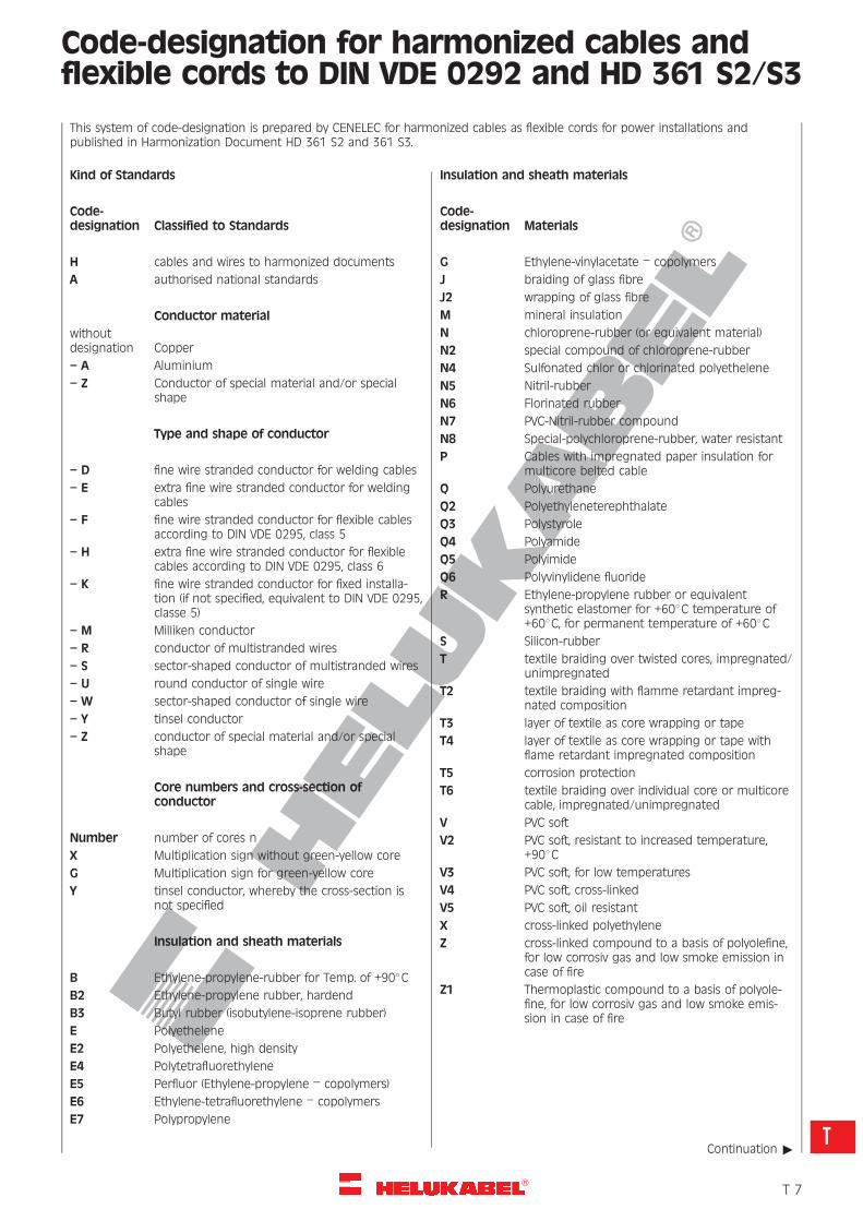
Code-designation for harmonized cables andflexible cords to DIN VDE 0292 and HD 361 S2/S3
This system of code-designation is prepared by CENELEC for harmonized cables as flexible cords for power installations andpublished in Harmonization Document HD 361 S2 and 361 S3.
Kind of Standards
Code-designation Classified to Standards
H cables and wires to harmonized documents
A authorised national standards
Conductor material
withoutdesignation Copper
– A Aluminium
– Z Conductor of special material and/or specialshape
Type and shape of conductor
– D fine wire stranded conductor for welding cables
– E extra fine wire stranded conductor for weldingcables
– F fine wire stranded conductor for flexible cablesaccording to DIN VDE 0295, class 5
– H extra fine wire stranded conductor for flexiblecables according to DIN VDE 0295, class 6
– K fine wire stranded conductor for fixed installa-tion (if not specified, equivalent to DIN VDE 0295,classe 5)
– M Milliken conductor
– R conductor of multistranded wires
– S sector-shaped conductor of multistranded wires
– U round conductor of single wire
– W sector-shaped conductor of single wire
– Y tinsel conductor
– Z conductor of special material and/or specialshape
Core numbers and cross-section ofconductor
Number number of cores n
X Multiplication sign without green-yellow core
G Multiplication sign for green-yellow core
Y tinsel conductor, whereby the cross-section isnot specified
Insulation and sheath materials
B Ethylene-propylene-rubber for Temp. of +908CB2 Ethylene-propylene rubber, hardend
B3 Butyl rubber (isobutylene-isoprene rubber)
E Polyethelene
E2 Polyethelene, high density
E4 Polytetrafluorethylene
E5 Perfluor (Ethylene-propylene – copolymers)
E6 Ethylene-tetrafluorethylene – copolymers
E7 Polypropylene
Insulation and sheath materials
Code-designation Materials
G Ethylene-vinylacetate – copolymers
J braiding of glass fibre
J2 wrapping of glass fibre
M mineral insulation
N chloroprene-rubber (or equivalent material)
N2 special compound of chloroprene-rubber
N4 Sulfonated chlor or chlorinated polyethelene
N5 Nitril-rubber
N6 Florinated rubber
N7 PVC-Nitril-rubber compound
N8 Special-polychloroprene-rubber, water resistant
P Cables with impregnated paper insulation formulticore belted cable
Q Polyurethane
Q2 Polyethyleneterephthalate
Q3 Polystyrole
Q4 Polyamide
Q5 Polyimide
Q6 Polyvinylidene fluoride
R Ethylene-propylene rubber or equivalentsynthetic elastomer for +608C temperature of+608C, for permanent temperature of +608C
S Silicon-rubber
T textile braiding over twisted cores, impregnated/unimpregnated
T2 textile braiding with flamme retardant impreg-nated composition
T3 layer of textile as core wrapping or tape
T4 layer of textile as core wrapping or tape withflame retardant impregnated composition
T5 corrosion protection
T6 textile braiding over individual core or multicorecable, impregnated/unimpregnated
V PVC soft
V2 PVC soft, resistant to increased temperature,+908C
V3 PVC soft, for low temperatures
V4 PVC soft, cross-linked
V5 PVC soft, oil resistant
X cross-linked polyethylene
Z cross-linked compound to a basis of polyolefine,for low corrosiv gas and low smoke emission incase of fire
Z1 Thermoplastic compound to a basis of polyole-fine, for low corrosiv gas and low smoke emis-sion in case of fire
Continuation "
�T 7
T
R
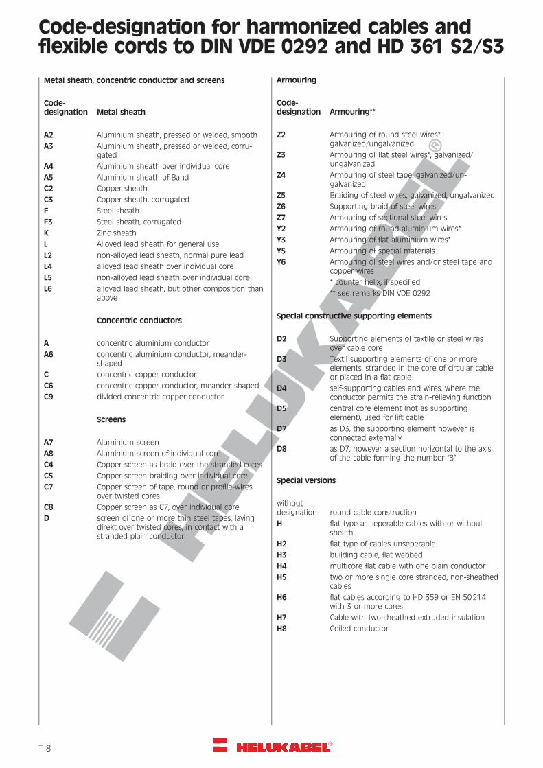
Code-designation for harmonized cables andflexible cords to DIN VDE 0292 and HD 361 S2/S3
Metal sheath, concentric conductor and screens
Code-designation Metal sheath
A2 Aluminium sheath, pressed or welded, smooth
A3 Aluminium sheath, pressed or welded, corru-gated
A4 Aluminium sheath over individual core
A5 Aluminium sheath of Band
C2 Copper sheath
C3 Copper sheath, corrugated
F Steel sheath
F3 Steel sheath, corrugated
K Zinc sheath
L Alloyed lead sheath for general use
L2 non-alloyed lead sheath, normal pure lead
L4 alloyed lead sheath over individual core
L5 non-alloyed lead sheath over individual core
L6 alloyed lead sheath, but other composition thanabove
Concentric conductors
A concentric aluminium conductor
A6 concentric aluminium conductor, meander-shaped
C concentric copper-conductor
C6 concentric copper-conductor, meander-shaped
C9 divided concentric copper conductor
Screens
A7 Aluminium screen
A8 Aluminium screen of individual core
C4 Copper screen as braid over the stranded cores
C5 Copper screen braiding over individual core
C7 Copper screen of tape, round or profile-wiresover twisted cores
C8 Copper screen as C7, over individual core
D screen of one or more thin steel tapes, layingdirekt over twisted cores, in contact with astranded plain conductor
Armouring
Code-designation Armouring**
Z2 Armouring of round steel wires*,galvanized/ungalvanized
Z3 Armouring of flat steel wires*, galvanized/ungalvanized
Z4 Armouring of steel tape, galvanized/un-galvanized
Z5 Braiding of steel wires, galvanized, ungalvanized
Z6 Supporting braid of steel wires
Z7 Armouring of sectional steel wires
Y2 Armouring of round aluminium wires*
Y3 Armouring of flat aluminium wires*
Y5 Armouring of special materials
Y6 Armouring of steel wires and/or steel tape andcopper wires
* counter helix, if specified
** see remarks DIN VDE 0292
Special constructive supporting elements
D2 Supporting elements of textile or steel wiresover cable core
D3 Textil supporting elements of one or moreelements, stranded in the core of circular cableor placed in a flat cable
D4 self-supporting cables and wires, where theconductor permits the strain-relieving function
D5 central core element (not as supportingelement), used for lift cable
D7 as D3, the supporting element however isconnected externally
D8 as D7, however a section horizontal to the axisof the cable forming the number “8“
Special versions
withoutdesignation round cable construction
H flat type as seperable cables with or withoutsheath
H2 flat type of cables unseperable
H3 building cable, flat webbed
H4 multicore flat cable with one plain conductor
H5 two or more single core stranded, non-sheathedcables
H6 flat cables according to HD 359 or EN 50214with 3 or more cores
H7 Cable with two-sheathed extruded insulation
H8 Coiled conductor
�T 8
R
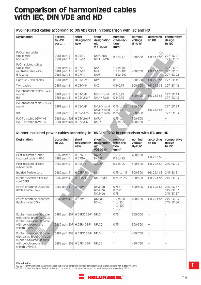
Comparison of harmonized cableswith IEC, DIN VDE and HD
PVC-insulated cables according to DIN VDE 0281 in comparison with IEC and HD
Designation accord.to VDEpart . . .
shortdesignationnew
shortdesignationoldVDE 0250
nominalcross-sec-tion(mm2)
nominalvoltageU0/U (V)
accordingto HD
comparativedesignto IEC
PVC-wiring cablessingle wirefine wires
0281 part 30281 part 3
H 05V-UH 05V-K
NYFA, NYANYFAF, NYAF
0,5 to 1,0 300/500 HD 21.3 S3 227 IEC 01227 IEC 01
PVC-insulated cablessingle wiremulti-stranded wiresfine wires
0281 part 30281 part 30281 part 3
H 07V-UH 07V-RH 07V-K
NYANYANYAF
1,5 to 101,5 to 4001,5 to 240
450/750 HD 21.3 S3227 IEC 01227 IEC 01227 IEC 02
Light PVC-Twin cables 0281 part 5 H 03VH-Y NLYZ 0,1 300/300 HD 21.5 S3 227 IEC 41
Twin cables 0281 part 5 H 03VH-H NYZ 0,5+0,75 300/300 HD 21.5 S3 227 IEC 42
PVC-sheathed cables 03VV-Froundflat
0281 part 50281 part 5
H 03VV-FH 03VVH2-F
NYLHY rundNYLHY flach
0,5+0,750,5+0,75
300/300 HD 21.5 S3 227 IEC 43227 IEC 43
PVC-sheathed cables 05 VV-Fround
flat
0281 part 5
0281 part 5
H 05VV-F
H 05VVH2-F
NYMHY rundNYMHY rundNYMHY flach
0,75 to 2,51 to 2,50,75
300/500
300/500HD 21.5 S3
227 IEC 53
227 IEC 53
PVC-Flat-cable 05VV-H6PVC-Flat-cable 07VV-H6
0281 part 4030281 part 404
H 05VVH6-FH 07VVH6-F
NYFLYNYFLY
0,75 to 11,5 to 25
300/500450/750 –
––
Rubber insulated power cables according to DIN VDE 0282 in comparison with IEC and HD
Designation accordingto VDE
shortdesignationnew
shortdesignationoldVDE 0250
nominalcross-sec-tion(mm2)
nominalvoltageU0/U (V)
accordingto HD
comparativedesignto IEC
Heat-resistant rubber-insulated cable H 07G
0282 part 70282 part 7
H 07G-UH 07G-K
N4GAN4GAF
1,5+2,50,5 to 95
450/750HD 22.7 S2
––
Heat-resistant silicone-rubber cable
0282 part 3 H 05SJ-K N2GAFU 0,5 to 95 300/500 HD 22.3 S2 245 IEC 03
Braided flexible cord 0282 part 4 H 03RT-F NSA 0,75 to 1,5 300/500 HD 22.4 S3 245 IEC 51
Rubber sheathed flexiblecord 05RR
0282 part 4 H 05RR-F NLH, NMH 0,75 to 2,5 300/500 HD 22.4 S3 245 IEC 53
Polychloroprene sheathedflexible cable 05RN
0282 part 4 H 05RN-F NYMHouNYMHouNYMHou
0,75+10,75+10,75
300/500 HD 22.4 S3 245 IEC 57245 IEC 57245 IEC 57
Polychloroprene sheathedflexible cable 07RN
0282 part 4 H 07RN-F NMHouNSHou
1,5 to 5001 to 251 to 3001,5+2,5
450/750 HD 22.4 S3 245 IEC 65245 IEC 66
Rubber insulated lift cablewith textile braid 05RT2D5Rubber insulated lift cablewith polychloroprenesheath 05RND5
0282 part 807
0282 part 807
H 05RT2D5-F
H 05RND5-F
NFLG
NFLGC
0,75
0,75
300/500
300/500
–
–
–
–
Rubber insulated lift cablewith textile braid 07RT2D5Rubber insulated lift cablewith polychloroprenesheath 07RND5
0282 part 808
0282 part 808
H 07RT2D5-F
H 07RND5-F
NFLG
NFLGC
1
1
450/750
450/750
–
–
–
–
IEC-definationIEC 227: Polyvinylchloride insulated flexible cables and cords with circular conductors and a rated voltage not exceeding 750 VIEC 245: Rubber insulated flexible cables and cords with circular conductors and a rated voltage not exceeding 750 V
�T 9
T
R
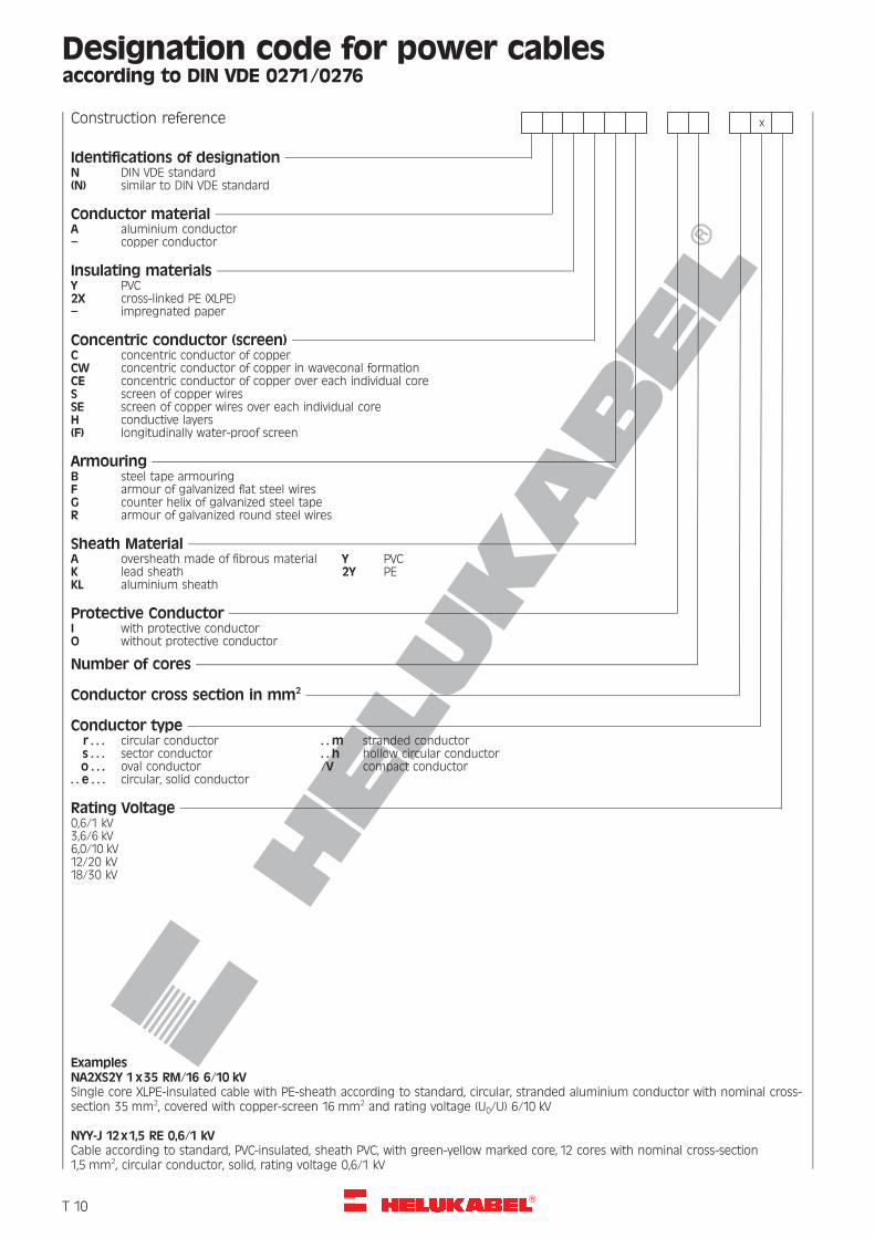
Designation code for power cablesaccording to DIN VDE 0271/0276
Construction reference x
Identifications of designationN DIN VDE standard(N) similar to DIN VDE standard
Conductor materialA aluminium conductor– copper conductor
Insulating materialsY PVC2X cross-linked PE (XLPE)– impregnated paper
Concentric conductor (screen)C concentric conductor of copperCW concentric conductor of copper in waveconal formationCE concentric conductor of copper over each individual coreS screen of copper wiresSE screen of copper wires over each individual coreH conductive layers(F) longitudinally water-proof screen
ArmouringB steel tape armouringF armour of galvanized flat steel wiresG counter helix of galvanized steel tapeR armour of galvanized round steel wires
Sheath MaterialA oversheath made of fibrous material Y PVCK lead sheath 2Y PEKL aluminium sheath
Protective ConductorI with protective conductorO without protective conductor
Number of cores
Conductor cross section in mm2
Conductor typer . . . circular conductor . . m stranded conductors . . . sector conductor . . h hollow circular conductoro . . . oval conductor /V compact conductor
. . e . . . circular, solid conductor
Rating Voltage0,6/1 kV3,6/6 kV6,0/10 kV12/20 kV18/30 kV
ExamplesNA2XS2Y 1x35 RM/16 6/10 kVSingle core XLPE-insulated cable with PE-sheath according to standard, circular, stranded aluminium conductor with nominal cross-section 35 mm2, covered with copper-screen 16 mm2 and rating voltage (U0/U) 6/10 kV
NYY-J 12x1,5 RE 0,6/1 kVCable according to standard, PVC-insulated, sheath PVC, with green-yellow marked core, 12 cores with nominal cross-section1,5 mm2, circular conductor, solid, rating voltage 0,6/1 kV
�T 10
R
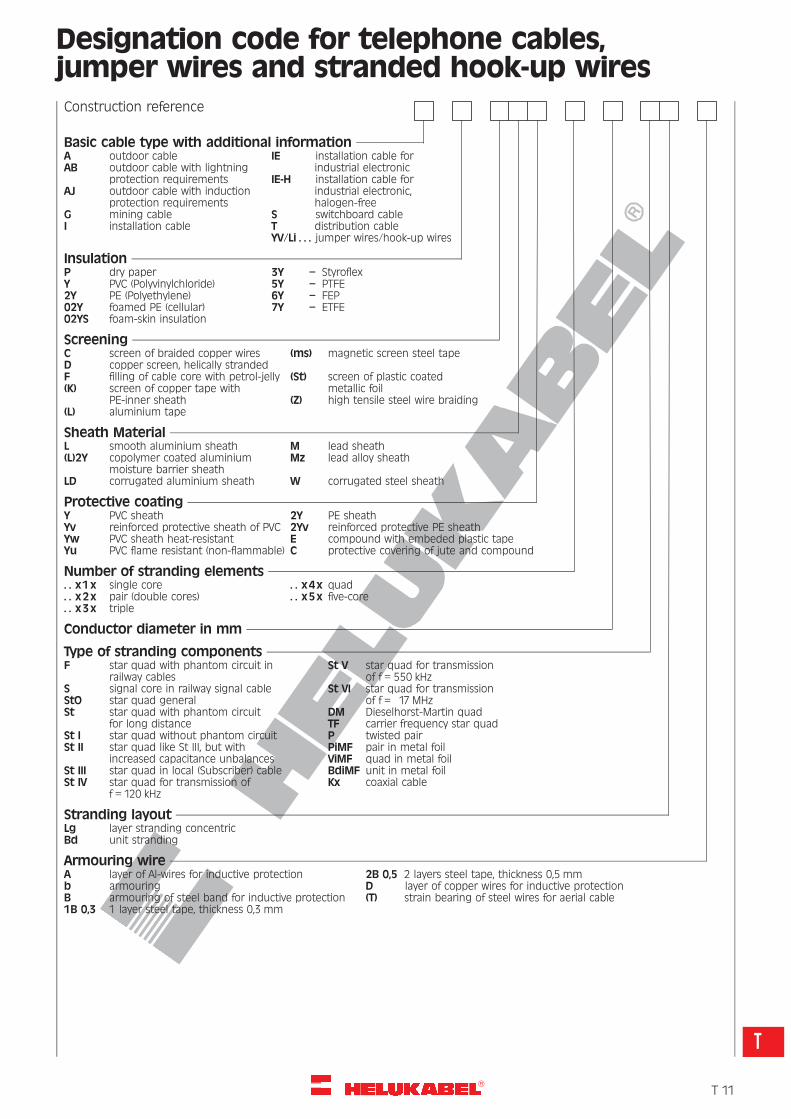
Designation code for telephone cables,jumper wires and stranded hook-up wiresConstruction reference
Basic cable type with additional informationA outdoor cable IE installation cable forAB outdoor cable with lightning industrial electronic
protection requirements IE-H installation cable forAJ outdoor cable with induction industrial electronic,
protection requirements halogen-freeG mining cable S switchboard cableI installation cable T distribution cable
YV/Li . . . jumper wires/hook-up wires
InsulationP dry paper 3Y – StyroflexY PVC (Polyvinylchloride) 5Y – PTFE2Y PE (Polyethylene) 6Y – FEP02Y foamed PE (cellular) 7Y – ETFE02YS foam-skin insulation
ScreeningC screen of braided copper wires (ms) magnetic screen steel tapeD copper screen, helically strandedF filling of cable core with petrol-jelly (St) screen of plastic coated(K) screen of copper tape with metallic foil
PE-inner sheath (Z) high tensile steel wire braiding(L) aluminium tape
Sheath MaterialL smooth aluminium sheath M lead sheath(L)2Y copolymer coated aluminium Mz lead alloy sheath
moisture barrier sheathLD corrugated aluminium sheath W corrugated steel sheath
Protective coatingY PVC sheath 2Y PE sheathYv reinforced protective sheath of PVC 2Yv reinforced protective PE sheathYw PVC sheath heat-resistant E compound with embeded plastic tapeYu PVC flame resistant (non-flammable) C protective covering of jute and compound
Number of stranding elements. . x1x single core . . x 4x quad. . x 2x pair (double cores) . . x 5x five-core. . x 3x triple
Conductor diameter in mm
Type of stranding componentsF star quad with phantom circuit in St V star quad for transmission
railway cables of f = 550 kHzS signal core in railway signal cable St VI star quad for transmissionStO star quad general of f = 17 MHzSt star quad with phantom circuit DM Dieselhorst-Martin quad
for long distance TF carrier frequency star quadSt I star quad without phantom circuit P twisted pairSt II star quad like St III, but with PiMF pair in metal foil
increased capacitance unbalances ViMF quad in metal foilSt III star quad in local (Subscriber) cable BdiMF unit in metal foilSt IV star quad for transmission of Kx coaxial cable
f = 120 kHz
Stranding layoutLg layer stranding concentricBd unit stranding
Armouring wireA layer of Al-wires for inductive protection 2B 0,5 2 layers steel tape, thickness 0,5 mmb armouring D layer of copper wires for inductive protectionB armouring of steel band for inductive protection (T) strain bearing of steel wires for aerial cable1B 0,3 1 layer steel tape, thickness 0,3 mm
�T 11
T
R
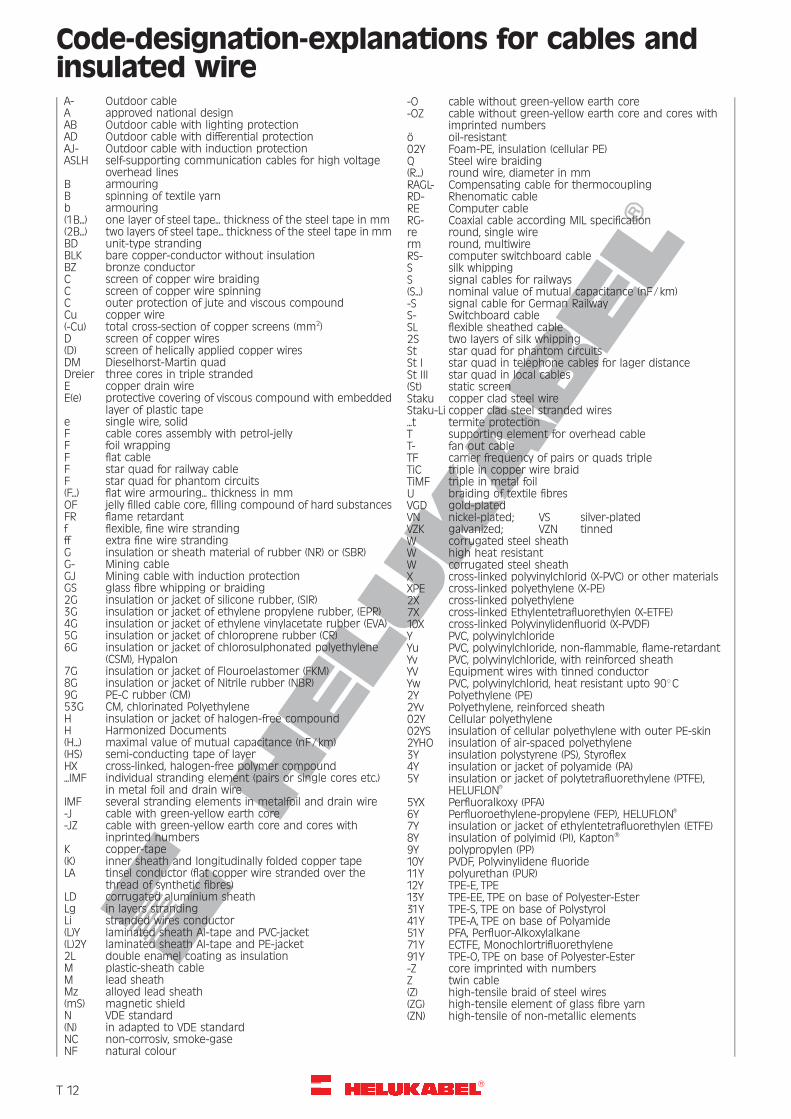
Code-designation-explanations for cables andinsulated wireA- Outdoor cableA approved national designAB Outdoor cable with lighting protectionAD Outdoor cable with differential protectionAJ- Outdoor cable with induction protectionASLH self-supporting communication cables for high voltage
overhead linesB armouringB spinning of textile yarnb armouring(1B...) one layer of steel tape... thickness of the steel tape in mm(2B...) two layers of steel tape... thickness of the steel tape in mmBD unit-type strandingBLK bare copper-conductor without insulationBZ bronze conductorC screen of copper wire braidingC screen of copper wire spinningC outer protection of jute and viscous compoundCu copper wire(-Cu) total cross-section of copper screens (mm2)D screen of copper wires(D) screen of helically applied copper wiresDM Dieselhorst-Martin quadDreier three cores in triple strandedE copper drain wireE(e) protective covering of viscous compound with embedded
layer of plastic tapee single wire, solidF cable cores assembly with petrol-jellyF foil wrappingF flat cableF star quad for railway cableF star quad for phantom circuits(F...) flat wire armouring... thickness in mmOF jelly filled cable core, filling compound of hard substancesFR flame retardantf flexible, fine wire strandingff extra fine wire strandingG insulation or sheath material of rubber (NR) or (SBR)G- Mining cableGJ Mining cable with induction protectionGS glass fibre whipping or braiding2G insulation or jacket of silicone rubber, (SIR)3G insulation or jacket of ethylene propylene rubber, (EPR)4G insulation or jacket of ethylene vinylacetate rubber (EVA)5G insulation or jacket of chloroprene rubber (CR)6G insulation or jacket of chlorosulphonated polyethylene
(CSM), Hypalon7G insulation or jacket of Flouroelastomer (FKM)8G insulation or jacket of Nitrile rubber (NBR)9G PE-C rubber (CM)53G CM, chlorinated PolyethyleneH insulation or jacket of halogen-free compoundH Harmonized Documents(H...) maximal value of mutual capacitance (nF/km)(HS) semi-conducting tape of layerHX cross-linked, halogen-free polymer compound...IMF individual stranding element (pairs or single cores etc.)
in metal foil and drain wireIMF several stranding elements in metalfoil and drain wire-J cable with green-yellow earth core-JZ cable with green-yellow earth core and cores with
inprinted numbersK copper-tape(K) inner sheath and longitudinally folded copper tapeLA tinsel conductor (flat copper wire stranded over the
thread of synthetic fibres)LD corrugated aluminium sheathLg in layers strandingLi stranded wires conductor(L)Y laminated sheath AI-tape and PVC-jacket(L)2Y laminated sheath AI-tape and PE-jacket2L double enamel coating as insulationM plastic-sheath cableM lead sheathMz alloyed lead sheath(mS) magnetic shieldN VDE standard(N) in adapted to VDE standardNC non-corrosiv, smoke-gaseNF natural colour
-O cable without green-yellow earth core-OZ cable without green-yellow earth core and cores with
imprinted numberso oil-resistant02Y Foam-PE, insulation (cellular PE)Q Steel wire braiding(R...) round wire, diameter in mmRAGL- Compensating cable for thermocouplingRD- Rhenomatic cableRE Computer cableRG- Coaxial cable according MIL specificationre round, single wirerm round, multiwireRS- computer switchboard cableS silk whippingS signal cables for railways(S...) nominal value of mutual capacitance (nF/km)-S signal cable for German RailwayS- Switchboard cableSL flexible sheathed cable2S two layers of silk whippingSt star quad for phantom circuitsSt I star quad in telephone cables for lager distanceSt III star quad in local cables(St) static screenStaku copper clad steel wireStaku-Li copper clad steel stranded wires...t termite protectionT supporting element for overhead cableT- fan out cableTF carrier frequency of pairs or quads tripleTiC triple in copper wire braidTiMF triple in metal foilU braiding of textile fibresVGD gold-platedVN nickel-plated; VS silver-platedVZK galvanized; VZN tinnedW corrugated steel sheathW high heat resistantW corrugated steel sheathX cross-linked polyvinylchlorid (X-PVC) or other materialsXPE cross-linked polyethylene (X-PE)2X cross-linked polyethylene7X cross-linked Ethylentetrafluorethylen (X-ETFE)10X cross-linked Polyvinylidenfluorid (X-PVDF)Y PVC, polyvinylchlorideYu PVC, polyvinylchloride, non-flammable, flame-retardantYv PVC, polyvinylchloride, with reinforced sheathYV Equipment wires with tinned conductorYw PVC, polyvinylchlorid, heat resistant upto 908C2Y Polyethylene (PE)2Yv Polyethylene, reinforced sheath02Y Cellular polyethylene02YS insulation of cellular polyethylene with outer PE-skin2YHO insulation of air-spaced polyethylene3Y insulation polystyrene (PS), Styroflex4Y insulation or jacket of polyamide (PA)5Y insulation or jacket of polytetrafluorethylene (PTFE),
HELUFLON�
5YX Perfluoralkoxy (PFA)6Y Perfluoroethylene-propylene (FEP), HELUFLON�
7Y insulation or jacket of ethylentetrafluorethylen (ETFE)8Y insulation of polyimid (PI), Kapton�
9Y polypropylen (PP)10Y PVDF, Polyvinylidene fluoride11Y polyurethan (PUR)12Y TPE-E, TPE13Y TPE-EE, TPE on base of Polyester-Ester31Y TPE-S, TPE on base of Polystyrol41Y TPE-A, TPE on base of Polyamide51Y PFA, Perfluor-Alkoxylalkane71Y ECTFE, Monochlortrifluorethylene91Y TPE-O, TPE on base of Polyester-Ester-Z core imprinted with numbersZ twin cable(Z) high-tensile braid of steel wires(ZG) high-tensile element of glass fibre yarn(ZN) high-tensile of non-metallic elements
�T 12
R
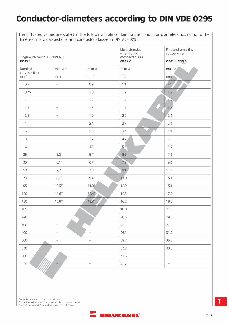
Conductor-diameters according to DIN VDE 0295
The indicated values are stated in the following table containing the conductor diameters according to thedimension of cross-sections and conductor classes in DIN VDE 0295.
Single-wire round (Cu and Alu)Class 1
Multi strandedwires, roundcompacted (Cu)class 2
Fine and extra-finecopper wires
class 5 and 6
Nominal-cross-sectionmm2
min-1 3)
mm
max-1
mm
max-1
mm
max-1
mm
0,5 – 0,9 1,1 1,1
0,75 – 1,0 1,2 1,3
1 – 1,2 1,4 1,5
1,5 – 1,5 1,7 1,8
2,5 – 1,9 2,2 2,3
4 – 2,4 2,7 2,9
6 – 2,9 3,3 3,9
10 – 3,7 4,2 5,1
16 – 4,6 5,3 6,3
25 5,21) 5,72) 6,6 7,8
35 6,11) 6,72) 7,9 9,2
50 7,21) 7,82) 9,1 11,0
70 8,71) 9,42) 11,0 13,1
95 10,31) 11,02) 12,9 15,1
120 11,61) 12,42) 14,5 17,0
150 12,91) 13,82) 16,2 19,0
185 – – 18,0 21,0
240 – – 20,6 24,0
300 – – 23,1 27,0
400 – – 26,1 31,0
500 – – 29,2 35,0
630 – – 33,2 39,0
800 – – 37,6 –
1000 – – 42,2 –
1) only for Aluminium round conductor2) for mineral-insulated round conductor, only for copper3) min-1 for round Cu-conductor are not scheduled
�T 13
T
R
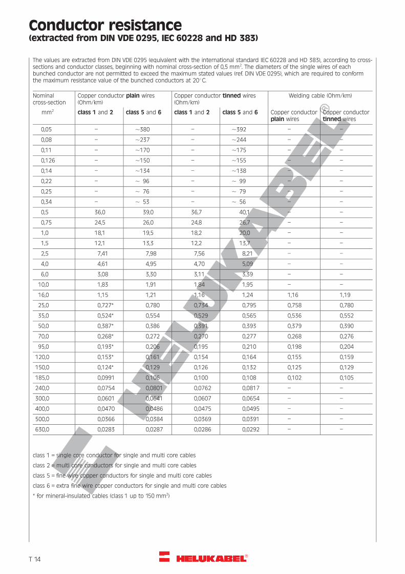
Conductor resistance(extracted from DIN VDE 0295, IEC 60228 and HD 383)
The values are extracted from DIN VDE 0295 (equivalent with the international standard IEC 60228 and HD 383), according to cross-sections and conductor classes, beginning with nominal cross-section of 0,5 mm2. The diameters of the single wires of eachbunched conductor are not permitted to exceed the maximum stated values (ref. DIN VDE 0295), which are required to conformthe maximum resistance value of the bunched conductors at 208C.
Nominalcross-section
Copper conductor plain wires(Ohm/km)
Copper conductor tinned wires(Ohm/km)
Welding cable (Ohm/km)
mm2 class 1 and 2 class 5 and 6 class 1 and 2 class 5 and 6 Copper conductorplain wires
Copper conductortinned wires
0,05 – ,380 – ,392 – –
0,08 – ,237 – ,244 – –
0,11 – ,170 – ,175 – –
0,126 – ,150 – ,155 – –
0,14 – ,134 – ,138 – –
0,22 – , 96 – , 99 – –
0,25 – , 76 – , 79 – –
0,34 – , 53 – , 56 – –
0,5 36,0 39,0 36,7 40,1 – –
0,75 24,5 26,0 24,8 26,7 – –
1,0 18,1 19,5 18,2 20,0 – –
1,5 12,1 13,3 12,2 13,7 – –
2,5 7,41 7,98 7,56 8,21 – –
4,0 4,61 4,95 4,70 5,09 – –
6,0 3,08 3,30 3,11 3,39 – –
10,0 1,83 1,91 1,84 1,95 – –
16,0 1,15 1,21 1,16 1,24 1,16 1,19
25,0 0,727* 0,780 0,734 0,795 0,758 0,780
35,0 0,524* 0,554 0,529 0,565 0,536 0,552
50,0 0,387* 0,386 0,391 0,393 0,379 0,390
70,0 0,268* 0,272 0,270 0,277 0,268 0,276
95,0 0,193* 0,206 0,195 0,210 0,198 0,204
120,0 0,153* 0,161 0,154 0,164 0,155 0,159
150,0 0,124* 0,129 0,126 0,132 0,125 0,129
185,0 0,0991 0,106 0,100 0,108 0,102 0,105
240,0 0,0754 0,0801 0,0762 0,0817 – –
300,0 0,0601 0,0641 0,0607 0,0654 – –
400,0 0,0470 0,0486 0,0475 0,0495 – –
500,0 0,0366 0,0384 0,0369 0,0391 – –
630,0 0,0283 0,0287 0,0286 0,0292 – –
class 1 = single core conductor for single and multi core cables
class 2 =multi core conductors for single and multi core cables
class 5 = fine wire copper conductors for single and multi core cables
class 6 = extra fine wire copper conductors for single and multi core cables
* for mineral-insulated cables (class 1 up to 150 mm2)
�T 14
R
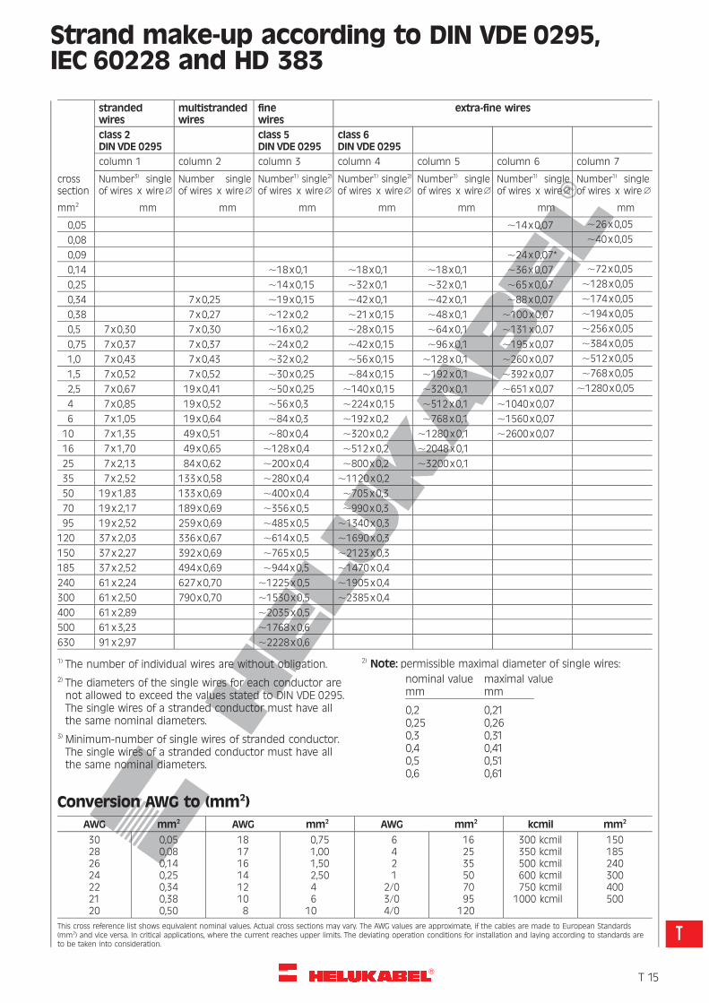
Strand make-up according to DIN VDE 0295,IEC 60228 and HD 383
strandedwires
multistrandedwires
finewires
extra-fine wires
class 2DIN VDE 0295
class 5DIN VDE 0295
class 6DIN VDE 0295
crosssection
column 1 column 2 column 3 column 4 column 5 column 6 column 7
Number3) singleof wires x wire1
Number singleof wires x wire1
Number1) single2)
of wires x wire1Number1) single2)
of wires x wire1Number1) singleof wires x wire1
Number1) singleof wires x wire1
Number1) singleof wires x wire1
mm2 mm mm mm mm mm mm mm
0,05 ,14x0,07 ,26x0,05
0,08 ,40x0,05
0,09 ,24x0,07*
0,14 ,18x0,1 ,18x0,1 ,18x0,1 ,36x0,07 ,72x0,05
0,25 ,14x0,15 ,32x0,1 ,32x0,1 ,65x0,07 ,128x0,05
0,34 7x0,25 ,19x0,15 ,42x0,1 ,42x0,1 ,88x0,07 ,174x0,05
0,38 7x0,27 ,12x0,2 ,21x0,15 ,48x0,1 ,100x0,07 ,194x0,05
0,5 7x0,30 7x0,30 ,16x0,2 ,28x0,15 ,64x0,1 ,131x0,07 ,256x0,05
0,75 7x0,37 7x0,37 ,24x0,2 ,42x0,15 ,96x0,1 ,195x0,07 ,384x0,05
1,0 7x0,43 7x0,43 ,32x0,2 ,56x0,15 ,128x0,1 ,260x0,07 ,512x0,05
1,5 7x0,52 7x0,52 ,30x0,25 ,84x0,15 ,192x0,1 ,392x0,07 ,768x0,05
2,5 7x0,67 19x0,41 ,50x0,25 ,140x0,15 ,320x0,1 ,651x0,07 ,1280x0,05
4 7x0,85 19x0,52 ,56x0,3 ,224x0,15 ,512x0,1 ,1040x0,07
6 7x1,05 19x0,64 ,84x0,3 ,192x0,2 ,768x0,1 ,1560x0,07
10 7x1,35 49x0,51 ,80x0,4 ,320x0,2 ,1280x0,1 ,2600x0,07
16 7x1,70 49x0,65 ,128x0,4 ,512x0,2 ,2048x0,1
25 7x2,13 84x0,62 ,200x0,4 ,800x0,2 ,3200x0,1
35 7x2,52 133x0,58 ,280x0,4 ,1120x0,2
50 19x1,83 133x0,69 ,400x0,4 ,705x0,3
70 19x2,17 189x0,69 ,356x0,5 ,990x0,3
95 19x2,52 259x0,69 ,485x0,5 ,1340x0,3
120 37x2,03 336x0,67 ,614x0,5 ,1690x0,3
150 37x2,27 392x0,69 ,765x0,5 ,2123x0,3
185 37x2,52 494x0,69 ,944x0,5 ,1470x0,4
240 61x2,24 627x0,70 ,1225x0,5 ,1905x0,4
300 61x2,50 790x0,70 ,1530x0,5 ,2385x0,4
400 61x2,89 ,2035x0,5
500 61x3,23 ,1768x0,6
630 91x2,97 ,2228x0,6
1) The number of individual wires are without obligation.2) The diameters of the single wires for each conductor arenot allowed to exceed the values stated to DIN VDE 0295.The single wires of a stranded conductor must have allthe same nominal diameters.
3) Minimum-number of single wires of stranded conductor.The single wires of a stranded conductor must have allthe same nominal diameters.
2) Note: permissible maximal diameter of single wires:
nominal value maximal valuemm mm
0,2 0,210,25 0,260,3 0,310,4 0,410,5 0,510,6 0,61
Conversion AWG to (mm2)
AWG mm2 AWG mm2 AWG mm2 kcmil mm2
30282624222120
0,050,080,140,250,340,380,50
1817161412108
0,751,001,502,5046
10
6421
2/03/04/0
162535507095
120
300 kcmil350 kcmil500 kcmil600 kcmil750 kcmil
1000 kcmil
150185240300400500
This cross reference list shows equivalent nominal values. Actual cross sections may vary. The AWG values are approximate, if the cables are made to European Standards(mm2) and vice versa. In critical applications, where the current reaches upper limits. The deviating operation conditions for installation and laying according to standards areto be taken into consideration.
�T 15
T
R
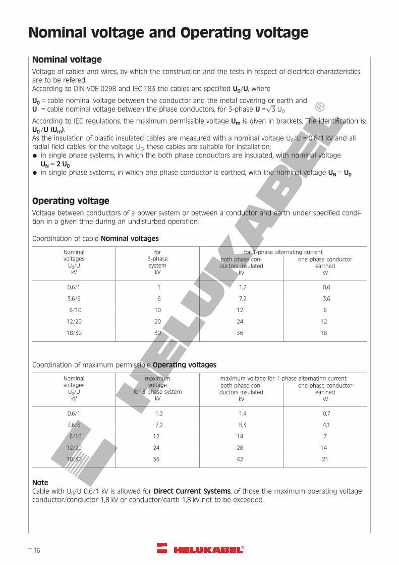
Nominal voltage and Operating voltage
Nominal voltage
Voltage of cables and wires, by which the construction and the tests in respect of electrical characteristicsare to be refered.According to DIN VDE 0298 and IEC 183 the cables are specified U0/U, where
U0 = cable nominal voltage between the conductor and the metal covering or earth andU = cable nominal voltage between the phase conductors, for 3-phase U =
ffiffiffi
3p
U0
According to IEC regulations, the maximum permissible voltage Um is given in brackets. The identification is:U0/U (Um).As the insulation of plastic insulated cables are measured with a nominal voltage U0/U = 0,6/1 kV and allradial field cables for the voltage U0, these cables are suitable for installation:* in single phase systems, in which the both phase conductors are insulated, with nominal voltage
UN = 2 U0* in single phase systems, in which one phase conductor is earthed, with the nominal voltage UN = U0
Operating voltage
Voltage between conductors of a power system or between a conductor and earth under specified condi-tion in a given time during an undisturbed operation.
Coordination of cable-Nominal voltages
NominalvoltagesU0/UkV
for3-phasesystem
kV
for 1-phase alternating currentboth phase con-ductors insulated
kV
one phase conductorearthed
kV
0,6/1 1 1,2 0,6
3,6/6 6 7,2 3,6
6/10 10 12 6
12/20 20 24 12
18/30 30 36 18
Coordination of maximum permissible Operating voltages
NominalvoltagesU0/UkV
maximumvoltage
for 3-phase systemkV
maximum voltage for 1-phase alternating currentboth phase con-ductors insulated
kV
one phase conductorearthed
kV
0,6/1 1,2 1,4 0,7
3,6/6 7,2 8,3 4,1
6/10 12 14 7
12/20 24 28 14
18/30 36 42 21
NoteCable with U0/U 0,6/1 kV is allowed for Direct Current Systems, of those the maximum operating voltageconductor/conductor 1,8 kV or conductor/earth 1,8 kV not to be exceeded.
�T 16
R
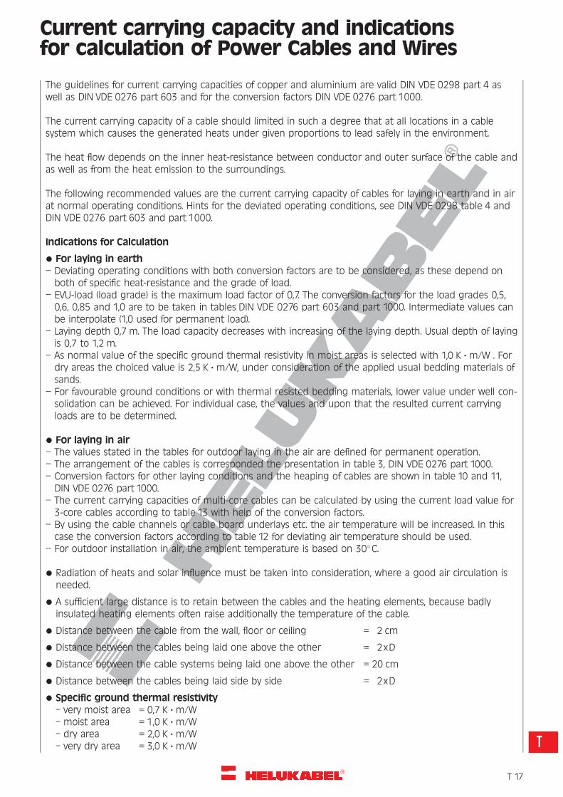
Current carrying capacity and indicationsfor calculation of Power Cables and Wires
The guidelines for current carrying capacities of copper and aluminium are valid DIN VDE 0298 part 4 aswell as DIN VDE 0276 part 603 and for the conversion factors DIN VDE 0276 part 1000.
The current carrying capacity of a cable should limited in such a degree that at all locations in a cablesystem which causes the generated heats under given proportions to lead safely in the environment.
The heat flow depends on the inner heat-resistance between conductor and outer surface of the cable andas well as from the heat emission to the surroundings.
The following recommended values are the current carrying capacity of cables for laying in earth and in airat normal operating conditions. Hints for the deviated operating conditions, see DIN VDE 0298 table 4 andDIN VDE 0276 part 603 and part 1000.
Indications for Calculation
* For laying in earth
– Deviating operating conditions with both conversion factors are to be considered, as these depend onboth of specific heat-resistance and the grade of load.
– EVU-load (load grade) is the maximum load factor of 0,7. The conversion factors for the load grades 0,5,0,6, 0,85 and 1,0 are to be taken in tables DIN VDE 0276 part 603 and part 1000. Intermediate values canbe interpolate (1,0 used for permanent load).
– Laying depth 0,7 m. The load capacity decreases with increasing of the laying depth. Usual depth of layingis 0,7 to 1,2 m.
– As normal value of the specific ground thermal resistivity in moist areas is selected with 1,0 K ? m/W . Fordry areas the choiced value is 2,5 K ? m/W, under consideration of the applied usual bedding materials ofsands.
– For favourable ground conditions or with thermal resisted bedding materials, lower value under well con-solidation can be achieved. For individual case, the values and upon that the resulted current carryingloads are to be determined.
* For laying in air
– The values stated in the tables for outdoor laying in the air are defined for permanent operation.
– The arrangement of the cables is corresponded the presentation in table 3, DIN VDE 0276 part 1000.
– Conversion factors for other laying conditions and the heaping of cables are shown in table 10 and 11,DIN VDE 0276 part 1000.
– The current carrying capacities of multi-core cables can be calculated by using the current load value for3-core cables according to table 13 with help of the conversion factors.
– By using the cable channels or cable board underlays etc. the air temperature will be increased. In thiscase the conversion factors according to table 12 for deviating air temperature should be used.
– For outdoor installation in air, the ambient temperature is based on 308C.
* Radiation of heats and solar influence must be taken into consideration, where a good air circulation isneeded.
* A sufficient large distance is to retain between the cables and the heating elements, because badlyinsulated heating elements often raise additionally the temperature of the cable.
* Distance between the cable from the wall, floor or ceiling = 2 cm
* Distance between the cables being laid one above the other = 2xD
* Distance between the cable systems being laid one above the other = 20 cm
* Distance between the cables being laid side by side = 2xD
* Specific ground thermal resistivity
– very moist area = 0,7 K ? m/W
– moist area = 1,0 K ? m/W
– dry area = 2,0 K ? m/W
– very dry area = 3,0 K ? m/W
�T 17
T
R
Installation Methods and Operating Conditions– Power cables and insulated wires for fixed installation –
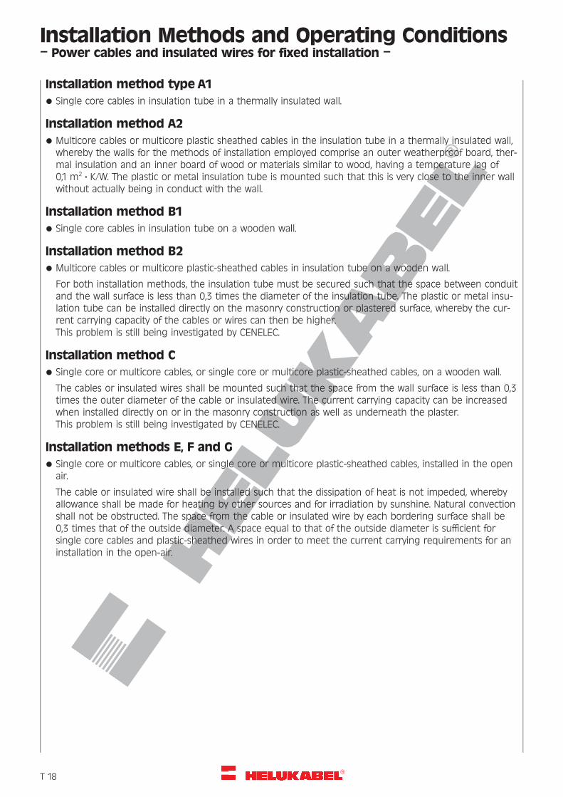
Installation method type A1* Single core cables in insulation tube in a thermally insulated wall.
Installation method A2* Multicore cables or multicore plastic sheathed cables in the insulation tube in a thermally insulated wall,
whereby the walls for the methods of installation employed comprise an outer weatherproof board, ther-mal insulation and an inner board of wood or materials similar to wood, having a temperature lag of0,1 m2 ? K/W. The plastic or metal insulation tube is mounted such that this is very close to the inner wallwithout actually being in conduct with the wall.
Installation method B1* Single core cables in insulation tube on a wooden wall.
Installation method B2* Multicore cables or multicore plastic-sheathed cables in insulation tube on a wooden wall.
For both installation methods, the insulation tube must be secured such that the space between conduitand the wall surface is less than 0,3 times the diameter of the insulation tube. The plastic or metal insu-lation tube can be installed directly on the masonry construction or plastered surface, whereby the cur-rent carrying capacity of the cables or wires can then be higher.This problem is still being investigated by CENELEC.
Installation method C* Single core or multicore cables, or single core or multicore plastic-sheathed cables, on a wooden wall.
The cables or insulated wires shall be mounted such that the space from the wall surface is less than 0,3times the outer diameter of the cable or insulated wire. The current carrying capacity can be increasedwhen installed directly on or in the masonry construction as well as underneath the plaster.This problem is still being investigated by CENELEC.
Installation methods E, F and G* Single core or multicore cables, or single core or multicore plastic-sheathed cables, installed in the open
air.
The cable or insulated wire shall be installed such that the dissipation of heat is not impeded, wherebyallowance shall be made for heating by other sources and for irradiation by sunshine. Natural convectionshall not be obstructed. The space from the cable or insulated wire by each bordering surface shall be0,3 times that of the outside diameter. A space equal to that of the outside diameter is sufficient forsingle core cables and plastic-sheathed wires in order to meet the current carrying requirements for aninstallation in the open-air.
�T 18
R
Laying Conditions for Power Cables
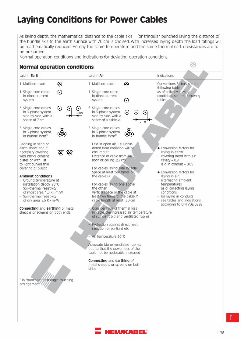
As laying depth, the mathematical distance to the cable axis – for tringular bunched laying the distance ofthe bundle axis to the earth surface with 70 cm is choised. With increased laying depth the load ratings willbe mathematically reduced. Hereby the same temperature and the same thermal earth resistances are tobe presumed.Normal operation conditions and indications for deviating operation conditions.
Normal operation conditions
Laid in Earth Laid in Air Indications
1 Multicore cable
1 Single core cablein direct current-system
3 Single core cablesin 3-phase system,side by side, with aspace of 7 cm
3 Single core cablesin 3-phase system,in bundle form1)
Bedding in sand orearth shove and ifnecessary coveringwith bricks, cementplates or with flatto light curved thincovering of plastic
Ambient conditions– Ground temperature at
installation depth: 208C– Soil-thermal resistivity
of moist area: 1,0 K ?m/W– Soil-thermal resistivity
of dry area: 2,5 K ? m/W
Connecting and earthing of metalsheaths or screens on both ends
1) in “bunched“ or triangle touchingarrangement
1 Multicore cable
1 Single core cablein direct currentsystem
3 Single core cablesin 3-phase system,side by side, with aspace of a cable 1
3 Single core cablesin 3-phase systemin bundle form1)
– Laid in open air, i. e. unhin-dered heat radiation will beensured at:Distance of cable from wall,floor or ceiling ^2 cm
– For cables laying side by side:Space at least two times ofthe cable 1
– For cables laying one abovethe other:Vertical space of the cable atleast two times of the cable 1
cable length at least 30 cm
– Consideration of thermal lossin cable, the increased air temperatureof sufficient big and ventilated rooms
– Protection against direct heatradiation of sunlight etc.
– Air temperature 308C
Adequate big or ventilated rooms,due to that the power loss of thecable not be noticeable increased
Connecting and earthing ofmetal sheaths or screens on bothsides
Conversions factors see thefollowing tablesas of collective layingconditions see the followingtables
* Conversion factors forlaying in earth:
– covering hood with aircavaty = 0,9
– laid in conduit = 0,85
* Conversion factors forlaying in air:
– alternating ambienttemperatures
– as of collecting layingconditions
– for laying in conduits– see tables and indications
according to DIN VDE 0298
�T 19
T
R
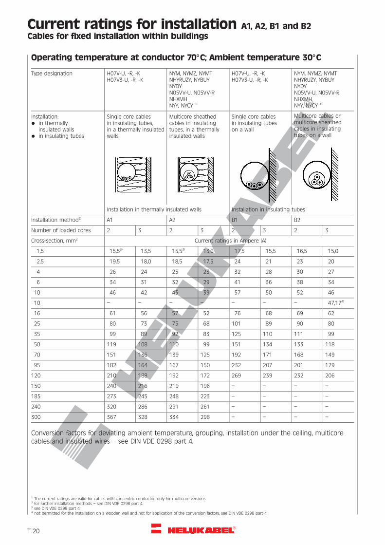
Current ratings for installation A1, A2, B1 and B2Cables for fixed installation within buildings
Operating temperature at conductor 708C; Ambient temperature 308C
Type designation H07V-U, -R, -KH07V3-U, -R, -K
NYM, NYMZ, NYMTNHYRUZY, NYBUYNYDYN05VV-U, N05VV-RNHXMHNYY, NYCY 1)
H07V-U, -R, -KH07V3-U, -R, -K
NYM, NYMZ, NYMTNHYRUZY, NYBUYNYDYN05VV-U, N05VV-RNHXMHNYY, NYCY 1)
Installation:* in thermally
insulated walls* in insulating tubes
Single core cablesin insulating tubes,in a thermally insulatedwalls
Multicore sheathedcables in insulatingtubes, in a thermallyinsulated walls
Single core cablesin insulating tubeson a wall
Multicore cables ormulticore sheathedcables in insulatingtubes on a wall
Installation in thermally insulated walls Installation in insulating tubes
Installation method2) A1 A2 B1 B2
Number of loaded cores 2 3 2 3 2 3 2 3
Cross-section, mm2 Current ratings in Ampere (A)
1,5 15,53) 13,5 15,53) 13,0 17,5 15,5 16,5 15,0
2,5 19,5 18,0 18,5 17,5 24 21 23 20
4 26 24 25 23 32 28 30 27
6 34 31 32 29 41 36 38 34
10 46 42 43 39 57 50 52 46
10 – – – – – – – 47,174)
16 61 56 57 52 76 68 69 62
25 80 73 75 68 101 89 90 80
35 99 89 92 83 125 110 111 99
50 119 108 110 99 151 134 133 118
70 151 136 139 125 192 171 168 149
95 182 164 167 150 232 207 201 179
120 210 188 192 172 269 239 232 206
150 240 216 219 196 – – – –
185 273 245 248 223 – – – –
240 320 286 291 261 – – – –
300 367 328 334 298 – – – –
Conversion factors for deviating ambient temperature, grouping, installation under the ceiling, multicorecables and insulated wires – see DIN VDE 0298 part 4.
1) The current ratings are valid for cables with concentric conductor, only for multicore versions2) for further installation methods – see DIN VDE 0298 part 43) see DIN VDE 0298 part 44) not permitted for the installation on a wooden wall and not for application of the conversion factors, see DIN VDE 0298 part 4
�T 20
R
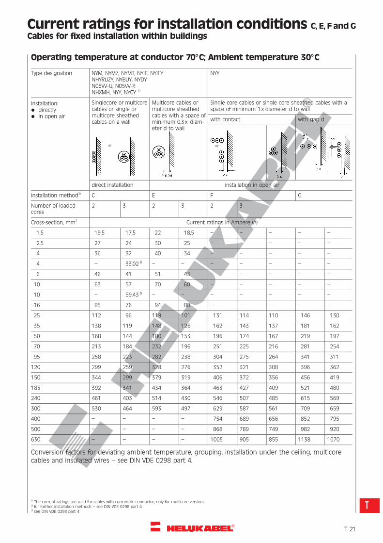
Current ratings for installation conditions C, E, F and GCables for fixed installation within buildings
Operating temperature at conductor 708C; Ambient temperature 308C
Type designation NYM, NYMZ, NYMT, NYIF, NYIFYNHYRUZY, NYBUY, NYDYN05VV-U, N05VV-RNHXMH, NYY, NYCY 1)
NYY
Installation:* directly* in open air
Singlecore or multicorecables or single ormulticore sheathedcables on a wall
Multicore cables ormulticore sheathedcables with a space ofminimum 0,3x diam-eter d to wall
Single core cables or single core sheathed cables with aspace of minimum 1x diameter d to wall
with contact with gap d
direct installation installation in open air
Installation method2) C E F G
Number of loadedcores
2 3 2 3 2 3
Cross-section, mm2 Current ratings in Ampere (A)
1,5 19,5 17,5 22 18,5 – – – – –
2,5 27 24 30 25 – – – – –
4 36 32 40 34 – – – – –
4 – 33,023)– – – – – – –
6 46 41 51 43 – – – – –
10 63 57 70 60 – – – – –
10 – 59,433) – – – – – – –
16 85 76 94 80 – – – – –
25 112 96 119 101 131 114 110 146 130
35 138 119 148 126 162 143 137 181 162
50 168 144 180 153 196 174 167 219 197
70 213 184 232 196 251 225 216 281 254
95 258 223 282 238 304 275 264 341 311
120 299 259 328 276 352 321 308 396 362
150 344 299 379 319 406 372 356 456 419
185 392 341 434 364 463 427 409 521 480
240 461 403 514 430 546 507 485 615 569
300 530 464 593 497 629 587 561 709 659
400 – – – – 754 689 656 852 795
500 – – – – 868 789 749 982 920
630 – – – – 1005 905 855 1138 1070
Conversion factors for deviating ambient temperature, grouping, installation under the ceiling, multicorecables and insulated wires – see DIN VDE 0298 part 4.
1) The current ratings are valid for cables with concentric conductor, only for multicore versions2) for further installation methods – see DIN VDE 0298 part 43) see DIN VDE 0298 part 4
or or
�T 21
T
R
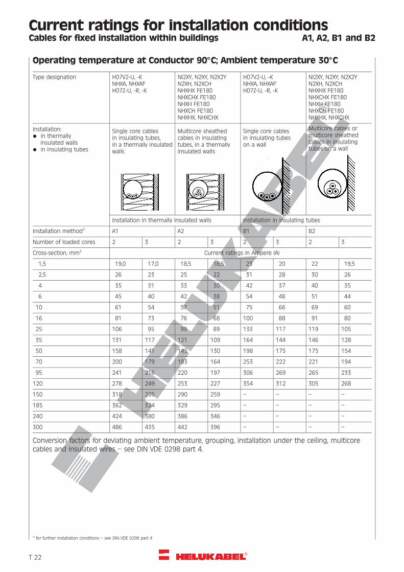
Current ratings for installation conditionsCables for fixed installation within buildings A1, A2, B1 and B2
Operating temperature at Conductor 908C; Ambient temperature 308C
Type designation H07V2-U, -KNHXA, NHXAFH07Z-U, -R, -K
NI2XY, N2XY, N2X2YN2XH, N2XCHNHXHX FE180NHXCHX FE180NHXH FE180NHXCH FE180NHXHX, NHXCHX
H07V2-U, -KNHXA, NHXAFH07Z-U, -R, -K
NI2XY, N2XY, N2X2YN2XH, N2XCHNHXHX FE180NHXCHX FE180NHXH FE180NHXCH FE180NHXHX, NHXCHX
Installation:* in thermally
insulated walls* in insulating tubes
Single core cablesin insulating tubes,in a thermally insulatedwalls
Multicore sheathedcables in insulatingtubes, in a thermallyinsulated walls
Single core cablesin insulating tubeson a wall
Multicore cables ormulticore sheathedcables in insulatingtubes on a wall
Installation in thermally insulated walls Installation in insulating tubes
Installation method1) A1 A2 B1 B2
Number of loaded cores 2 3 2 3 2 3 2 3
Cross-section, mm2 Current ratings in Ampere (A)
1,5 19,0 17,0 18,5 16,5 23 20 22 19,5
2,5 26 23 25 22 31 28 30 26
4 35 31 33 30 42 37 40 35
6 45 40 42 38 54 48 51 44
10 61 54 57 51 75 66 69 60
16 81 73 76 68 100 88 91 80
25 106 95 99 89 133 117 119 105
35 131 117 121 109 164 144 146 128
50 158 141 145 130 198 175 175 154
70 200 179 183 164 253 222 221 194
95 241 216 220 197 306 269 265 233
120 278 249 253 227 354 312 305 268
150 318 285 290 259 – – – –
185 362 324 329 295 – – – –
240 424 380 386 346 – – – –
300 486 435 442 396 – – – –
Conversion factors for deviating ambient temperature, grouping, installation under the ceiling, multicorecables and insulated wires – see DIN VDE 0298 part 4.
1) for further installation conditions – see DIN VDE 0298 part 4
�T 22
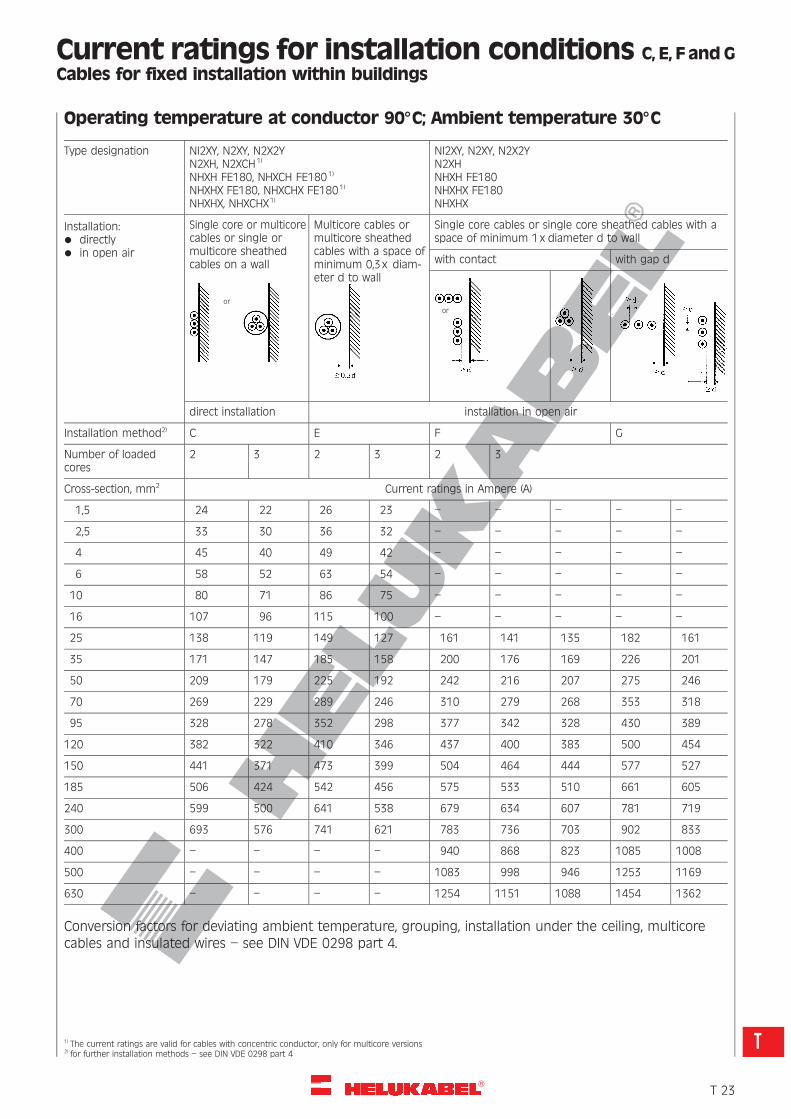
R
Current ratings for installation conditions C, E, F and GCables for fixed installation within buildings
Operating temperature at conductor 908C; Ambient temperature 308C
Type designation NI2XY, N2XY, N2X2YN2XH, N2XCH1)
NHXH FE180, NHXCH FE1801)
NHXHX FE180, NHXCHX FE1801)
NHXHX, NHXCHX1)
NI2XY, N2XY, N2X2YN2XHNHXH FE180NHXHX FE180NHXHX
Installation:* directly* in open air
Single core or multicorecables or single ormulticore sheathedcables on a wall
Multicore cables ormulticore sheathedcables with a space ofminimum 0,3x diam-eter d to wall
Single core cables or single core sheathed cables with aspace of minimum 1x diameter d to wall
with contact with gap d
direct installation installation in open air
Installation method2) C E F G
Number of loadedcores
2 3 2 3 2 3
Cross-section, mm2 Current ratings in Ampere (A)
1,5 24 22 26 23 – – – – –
2,5 33 30 36 32 – – – – –
4 45 40 49 42 – – – – –
6 58 52 63 54 – – – – –
10 80 71 86 75 – – – – –
16 107 96 115 100 – – – – –
25 138 119 149 127 161 141 135 182 161
35 171 147 185 158 200 176 169 226 201
50 209 179 225 192 242 216 207 275 246
70 269 229 289 246 310 279 268 353 318
95 328 278 352 298 377 342 328 430 389
120 382 322 410 346 437 400 383 500 454
150 441 371 473 399 504 464 444 577 527
185 506 424 542 456 575 533 510 661 605
240 599 500 641 538 679 634 607 781 719
300 693 576 741 621 783 736 703 902 833
400 – – – – 940 868 823 1085 1008
500 – – – – 1083 998 946 1253 1169
630 – – – – 1254 1151 1088 1454 1362
Conversion factors for deviating ambient temperature, grouping, installation under the ceiling, multicorecables and insulated wires – see DIN VDE 0298 part 4.
1) The current ratings are valid for cables with concentric conductor, only for multicore versions2) for further installation methods – see DIN VDE 0298 part 4
oror
�T 23
T
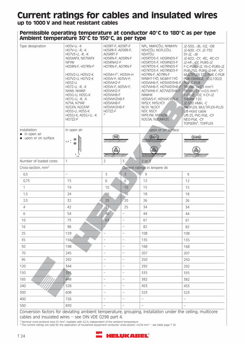
R
Current ratings for cables and insulated wiresup to 1000 V and heat resistant cables
Permissible operating temperature at conductor 408C to 1808C as per typeAmbient temperature 308C to 1508C, as per type
Type designation H05V-U, -KH07V-U, -R, -KH07V3-U, -R, -KN05XAFX, N07XAFXNFYWH05RN-F, H07RN-F
H05V2-U, H05V2-KH07V2-U, H07V2-KH05Z-UH07Z-U, -R, -KNHXA, NHXAFH05G-U, H05G-KH07G-U, -R, -KN7YA, N7YAFN2GFA, N2GFAFH05S-U, H05S-KH05SJ-K, A05SJ-U, -KH07ZZ-F
H03RT-F, A03RT-FH05RR-F, A05RR-F,A05RRT-FH05RN-F, A05RN-FH05RNH2-FH07RN-F, A07RN-F
H03VH-Y1), H03VH-HH03VV-F, A03VV-F,H03VVH2-FH05VV-F, A05VV-F,H05VVH2-FH03VVH8-FH03VVH2H8-FH05VVH8-FH05VVH2H8-FH07ZZ-F2)
NPL, NMHCOU, NYMHYVNSHCOU, NGFLGOU,NSHTOUH05RTD5-F, H05RND5-FH05RTD3-F, H05RND3-FH07RTD5-F, H07RND5-FH07RTD3-F, H07RND3-FH07RN-F, A07RN-FNYMH11YO, NGMH11YOH05VVH6-F, H05VVD3H6-FH07VVH6-F, H07VVD3H6-FA07VVH6-F, A07VVD3H6-FNXMHXH05VV5-F, H05VVC4V5-KNYSLY, NYSLYCYNLSY, NLSCYNSY, NSCYNYPLYW, NYFAZWN2GSA, N2GMH2G
JZ-500, -JB, -OZ, -OBJZ-600, -CY, JZ-750SY-JZ, -JBJZ-602, -CY, -RC, -RC-CYJZ-HF, -CY, PURo-JZF-C-PURo-JZ, Yo-C-PURo-JZPUR-750, PURo-JZ-HF, -CYMULTIFLEX 512 PUR, C-PURPUR-ORANGE, -{0,0,100,0}PUR-C-PURTRONIC ($0,5 mm2)TRONIC-CY ($0,5 mm2)F-CY-JZ, -OZ, Y-CY-JZTHERM 120JZ-500 HMH, -CBAUFLEX, MULTIFLEX-PLUSLift-Hoist cableLift-2S, PVC-Flat, -CYNEO-Flat, -CYTOPSERV�, TOPFLEX
Installation:* in open air* upon or on surface
in open air upon or on surface
Number of loaded cores 1 2 3 2 or 3
Cross-section, mm2 Current ratings in Ampere (A)
0,5 – 3 3 9 9
0,75 15 6 6 12 12
1 19 10 10 15 15
1,5 24 16 16 18 18
2,5 32 25 20 26 26
4 42 32 25 34 34
6 54 40 – 44 44
10 73 63 – 61 61
16 98 – – 82 82
25 129 – – 108 108
35 158 – – 135 135
50 198 – – 168 168
70 245 – – 207 207
95 292 – – 250 250
120 344 – – 292 292
150 391 – – 335 335
185 448 – – 382 382
240 528 – – 453 453
300 608 – – 523 523
400 726 – – – –
500 830 – – – –
Conversion factors for deviating ambient temperature, grouping, installation under the ceiling, multicorecables and insulated wires – see DIN VDE 0298 part 4.1) Nominal cross-sectional area 0,1 mm2, loadable with 0,2 A, independent of the ambient temperature2) The current ratings are valid for the application of household equipment conductor cross-section #0,34 mm2 – see table page T 26
�T 24
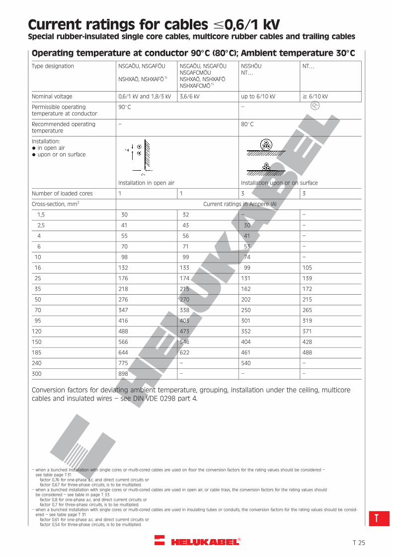
R
Current ratings for cables #0,6/1 kVSpecial rubber-insulated single core cables, multicore rubber cables and trailing cables
Operating temperature at conductor 908C (808C); Ambient temperature 308C
Type designation NSGAOU, NSGAFOU
NSHXAO, NSHXAFO 1)
NSGAOU, NSGAFOUNSGAFCMOUNSHXAO, NSHXAFONSHXAFCMO 1)
NSSHOUNT…
NT…
Nominal voltage 0,6/1 kV and 1,8/3 kV 3,6/6 kV up to 6/10 kV ^ 6/10 kV
Permissible operatingtemperature at conductor
908C –
Recommended operatingtemperature
– 808C
Installation:* in open air* upon or on surface
Installation in open air Installation upon or on surface
Number of loaded cores 1 1 3 3
Cross-section, mm2 Current ratings in Ampere (A)
1,5 30 32 – –
2,5 41 43 30 –
4 55 56 41 –
6 70 71 53 –
10 98 99 74 –
16 132 133 99 105
25 176 174 131 139
35 218 215 162 172
50 276 270 202 215
70 347 338 250 265
95 416 403 301 319
120 488 473 352 371
150 566 546 404 428
185 644 622 461 488
240 775 – 540 –
300 898 – – –
Conversion factors for deviating ambient temperature, grouping, installation under the ceiling, multicorecables and insulated wires – see DIN VDE 0298 part 4.
– when a bunched installation with single cores or multi-cored cables are used on floor the conversion factors for the rating values should be considered –see table page T31
factor 0,76 for one-phase a.c. and direct current circuits orfactor 0,67 for three-phase circuits, is to be multiplied.
– when a bunched installation with single cores or multi-cored cables are used in open air, or cable trays, the conversion factors for the rating values shouldbe considered – see table in page T 33
factor 0,8 for one-phase a.c. and direct current circuits orfactor 0,7 for three-phase circuits, is to be multiplied.
– when a bunched installation with single cores or multi-cored cables are used in insulating tubes or conduits, the conversion factors for the rating values should be consid-ered – see table page T 31
factor 0,61 for one-phase a.c. and direct current circuits orfactor 0,54 for three-phase circuits, is to be multiplied.
�T 25
T
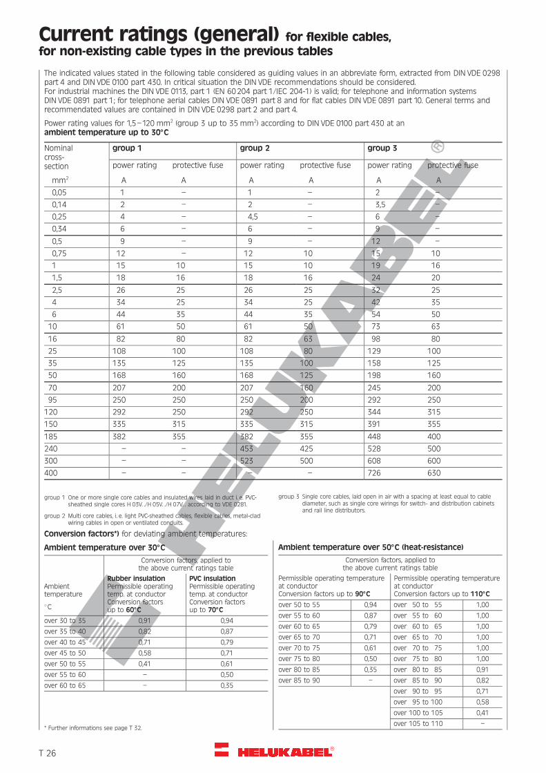
R
Current ratings (general) for flexible cables,for non-existing cable types in the previous tables
The indicated values stated in the following table considered as guiding values in an abbreviate form, extracted from DIN VDE 0298part 4 and DIN VDE 0100 part 430. In critical situation the DIN VDE recommendations should be considered.For industrial machines the DIN VDE 0113, part 1 (EN 60204 part 1/IEC 204-1) is valid; for telephone and information systemsDIN VDE 0891 part 1; for telephone aerial cables DIN VDE 0891 part 8 and for flat cables DIN VDE 0891 part 10. General terms andrecommendated values are contained in DIN VDE 0298 part 2 and part 4.
Power rating values for 1,5–120 mm2 (group 3 up to 35 mm2) according to DIN VDE 0100 part 430 at anambient temperature up to 308C
Nominalcross-section
mm2
group 1 group 2 group 3
power rating
A
protective fuse
A
power rating
A
protective fuse
A
power rating
A
protective fuse
A
0,05 1 – 1 – 2 –
0,14 2 – 2 – 3,5 –
0,25 4 – 4,5 – 6 –
0,34 6 – 6 – 9 –
0,5 9 – 9 – 12 –
0,75 12 – 12 10 15 10
1 15 10 15 10 19 16
1,5 18 16 18 16 24 20
2,5 26 25 26 25 32 25
4 34 25 34 25 42 35
6 44 35 44 35 54 50
10 61 50 61 50 73 63
16 82 80 82 63 98 80
25 108 100 108 80 129 100
35 135 125 135 100 158 125
50 168 160 168 125 198 160
70 207 200 207 160 245 200
95 250 250 250 200 292 250
120 292 250 292 250 344 315
150 335 315 335 315 391 355
185 382 355 382 355 448 400
240 – – 453 425 528 500
300 – – 523 500 608 600
400 – – – – 726 630
group 1 One or more single core cables and insulated wires laid in duct i. e. PVC-sheathed single cores H 03V. ./H 05V. ./H 07V. . according to VDE 0281.
group 2 Multi core cables, i. e. light PVC-sheathed cables, flexible cables, metal-cladwiring cables in open or ventilated conduits.
group 3 Single core cables, laid open in air with a spacing at least equal to cablediameter, such as single core wirings for switch- and distribution cabinetsand rail line distributors.
Ambient temperature over 308C
Conversion factors, applied tothe above current ratings table
Ambienttemperature
8C
Rubber insulationPermissible operatingtemp. at conductorConversion factorsup to 608C
PVC insulationPermissible operatingtemp. at conductorConversion factorsup to 708C
over 30 to 35 0,91 0,94
over 35 to 40 0,82 0,87
over 40 to 45 0,71 0,79
over 45 to 50 0,58 0,71
over 50 to 55 0,41 0,61
over 55 to 60 – 0,50
over 60 to 65 – 0,35
* Further informations see page T 32.
Ambient temperature over 508C (heat-resistance)
Conversion factors, applied tothe above current ratings table
Permissible operating temperatureat conductorConversion factors up to 908C
Permissible operating temperatureat conductorConversion factors up to 1108C
over 50 to 55 0,94 over 50 to 55 1,00
over 55 to 60 0,87 over 55 to 60 1,00
over 60 to 65 0,79 over 60 to 65 1,00
over 65 to 70 0,71 over 65 to 70 1,00
over 70 to 75 0,61 over 70 to 75 1,00
over 75 to 80 0,50 over 75 to 80 1,00
over 80 to 85 0,35 over 80 to 85 0,91
over 85 to 90 – over 85 to 90 0,82
over 90 to 95 0,71
over 95 to 100 0,58
over 100 to 105 0,41
over 105 to 110 –
Conversion factors*) for deviating ambient temperatures:
�T 26
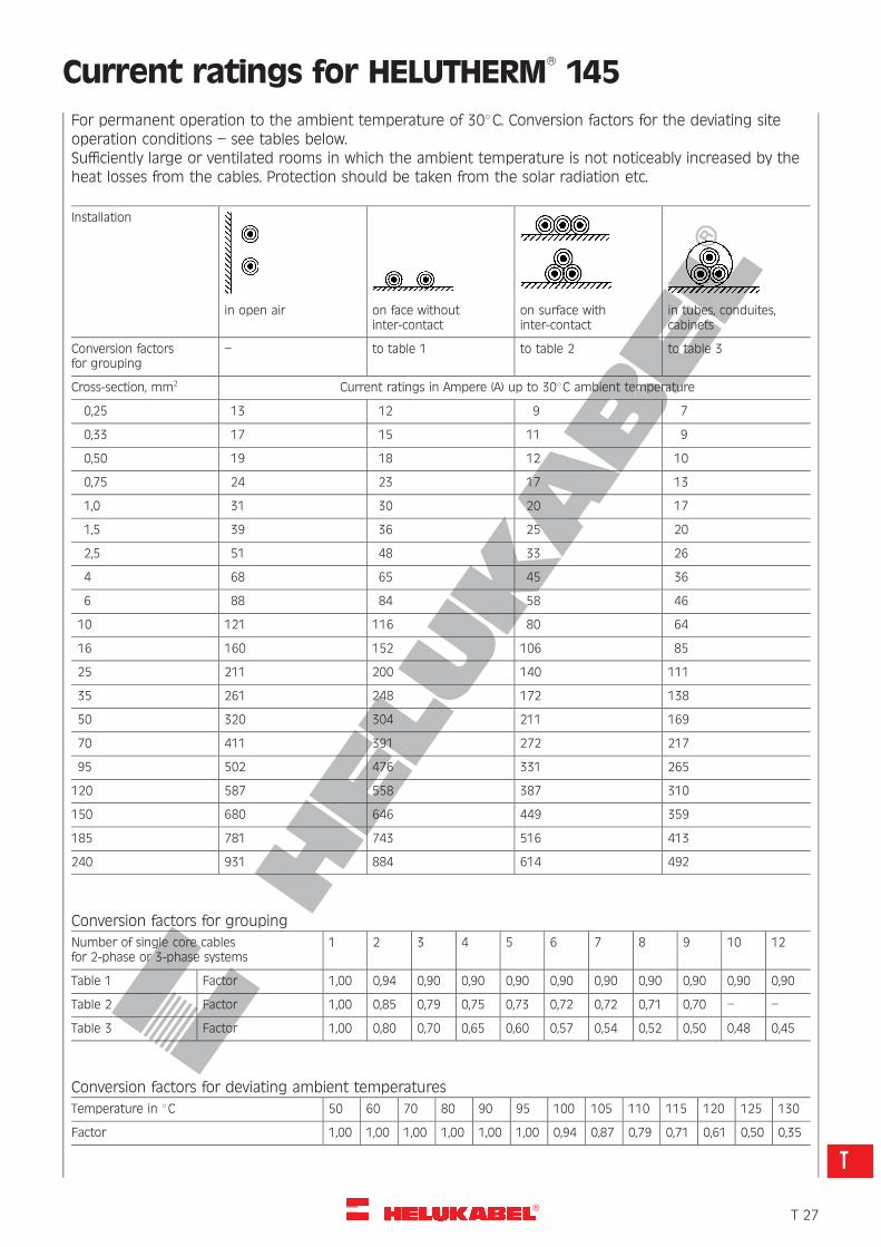
R
Current ratings for HELUTHERM�145
For permanent operation to the ambient temperature of 308C. Conversion factors for the deviating siteoperation conditions – see tables below.Sufficiently large or ventilated rooms in which the ambient temperature is not noticeably increased by theheat losses from the cables. Protection should be taken from the solar radiation etc.
Installation
in open air on face withoutinter-contact
on surface withinter-contact
in tubes, conduites,cabinets
Conversion factorsfor grouping
– to table 1 to table 2 to table 3
Cross-section, mm2 Current ratings in Ampere (A) up to 308C ambient temperature
0,25 13 12 9 7
0,33 17 15 11 9
0,50 19 18 12 10
0,75 24 23 17 13
1,0 31 30 20 17
1,5 39 36 25 20
2,5 51 48 33 26
4 68 65 45 36
6 88 84 58 46
10 121 116 80 64
16 160 152 106 85
25 211 200 140 111
35 261 248 172 138
50 320 304 211 169
70 411 391 272 217
95 502 476 331 265
120 587 558 387 310
150 680 646 449 359
185 781 743 516 413
240 931 884 614 492
Conversion factors for grouping
Number of single core cablesfor 2-phase or 3-phase systems
1 2 3 4 5 6 7 8 9 10 12
Table 1 Factor 1,00 0,94 0,90 0,90 0,90 0,90 0,90 0,90 0,90 0,90 0,90
Table 2 Factor 1,00 0,85 0,79 0,75 0,73 0,72 0,72 0,71 0,70 – –
Table 3 Factor 1,00 0,80 0,70 0,65 0,60 0,57 0,54 0,52 0,50 0,48 0,45
Conversion factors for deviating ambient temperatures
Temperature in 8C 50 60 70 80 90 95 100 105 110 115 120 125 130
Factor 1,00 1,00 1,00 1,00 1,00 1,00 0,94 0,87 0,79 0,71 0,61 0,50 0,35
�T 27
T
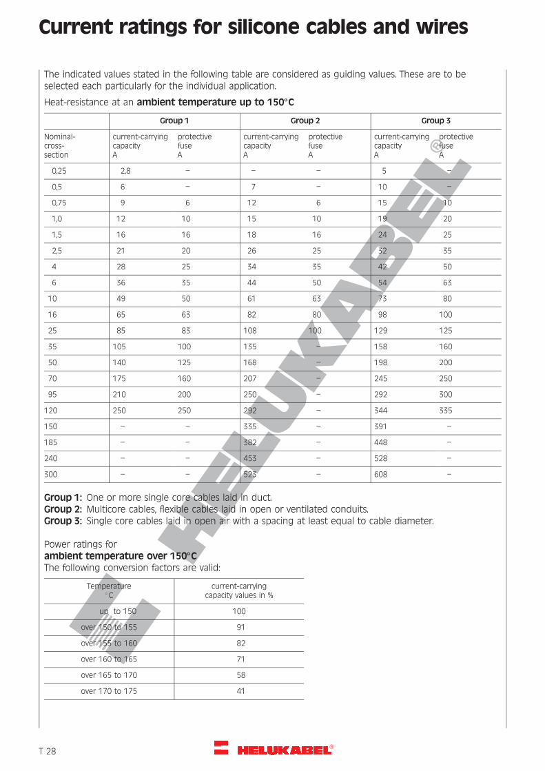
R
Current ratings for silicone cables and wires
The indicated values stated in the following table are considered as guiding values. These are to beselected each particularly for the individual application.
Heat-resistance at an ambient temperature up to 1508C
Group 1 Group 2 Group 3
Nominal-cross-section
current-carryingcapacityA
protectivefuseA
current-carryingcapacityA
protectivefuseA
current-carryingcapacityA
protectivefuseA
0,25 2,8 – – – 5 –
0,5 6 – 7 – 10 –
0,75 9 6 12 6 15 10
1,0 12 10 15 10 19 20
1,5 16 16 18 16 24 25
2,5 21 20 26 25 32 35
4 28 25 34 35 42 50
6 36 35 44 50 54 63
10 49 50 61 63 73 80
16 65 63 82 80 98 100
25 85 83 108 100 129 125
35 105 100 135 – 158 160
50 140 125 168 – 198 200
70 175 160 207 – 245 250
95 210 200 250 – 292 300
120 250 250 292 – 344 335
150 – – 335 – 391 –
185 – – 382 – 448 –
240 – – 453 – 528 –
300 – – 523 – 608 –
Group 1: One or more single core cables laid in duct.Group 2: Multicore cables, flexible cables laid in open or ventilated conduits.Group 3: Single core cables laid in open air with a spacing at least equal to cable diameter.
Power ratings forambient temperature over 1508CThe following conversion factors are valid:
Temperature8C
current-carryingcapacity values in %
up to 150 100
over 150 to 155 91
over 155 to 160 82
over 160 to 165 71
over 165 to 170 58
over 170 to 175 41
�T 28
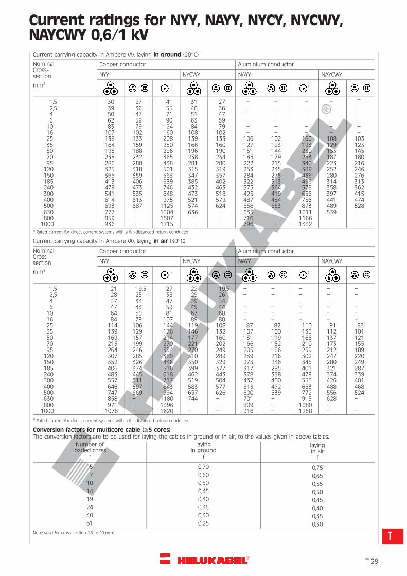
R
Current ratings for NYY, NAYY, NYCY, NYCWY,NAYCWY 0,6/1 kVCurrent carrying capacity in Ampere (A), laying in ground (208C)
NominalCross-section
mm2
Copper conductor Aluminium conductor
NYY NYCWY NAYY NAYCWY
1) 1)
1,5 30 27 41 31 27 – – – – –
2,5 39 36 55 40 36 – – – – –4 50 47 71 51 47 – – – – –6 62 59 90 63 59 – – – – –
10 83 79 124 84 79 – – – – –16 107 102 160 108 102 – – – – –25 138 133 208 139 133 106 102 160 108 10335 164 159 250 166 160 127 123 193 129 12350 195 188 296 196 190 151 144 230 153 14570 238 232 365 238 234 185 179 283 187 18095 286 280 438 281 280 222 215 340 223 216120 325 318 501 315 319 253 245 389 252 246150 365 359 563 347 357 284 275 436 280 276185 413 406 639 385 402 322 313 496 314 313240 479 473 746 432 463 375 364 578 358 362300 541 535 848 473 518 425 419 656 397 415400 614 613 975 521 579 487 484 756 441 474500 693 687 1125 574 624 558 553 873 489 528630 777 – 1304 636 – 635 – 1011 539 –800 859 – 1507 – – 716 – 1166 – –1000 936 – 1715 – – 796 – 1332 – –
1) Rated current for direct current systems with a far-distanced return conductor
Current carrying capacity in Ampere (A), laying in air (308C)
NominalCross-section
mm2
Copper conductor Aluminium conductor
NYY NYCWY NAYY NAYCWY
1) 1)
1,5 21 19,5 27 22 19,5 – – – – –2,5 28 25 35 29 26 – – – – –4 37 34 47 39 34 – – – – –6 47 43 59 49 44 – – – – –
10 64 59 81 67 60 – – – – –16 84 79 107 89 80 – – – – –25 114 106 144 119 108 87 82 110 91 8335 139 129 176 146 132 107 100 135 112 10150 169 157 214 177 160 131 119 166 137 12170 213 199 270 221 202 166 152 210 173 15595 264 246 334 270 249 205 186 259 212 189120 307 285 389 310 289 239 216 302 247 220150 352 326 446 350 329 273 246 345 280 249185 406 374 516 399 377 317 285 401 321 287240 483 445 618 462 443 378 338 479 374 339300 557 511 717 519 504 437 400 555 426 401400 646 597 843 583 577 513 472 653 488 468500 747 669 994 657 626 600 539 772 556 524630 858 – 1180 744 – 701 – 915 628 –800 971 – 1396 – – 809 – 1080 – –1000 1078 – 1620 – – 916 – 1258 – –
1) Rated current for direct current systems with a far-distanced return conductor
Conversion factors for multicore cable (^5 cores)The conversion factors are to be used for laying the cables in ground or in air, to the values given in above tables.
Number ofloaded cores
n
layingin ground
f
layingin airf
5 0,70 0,757 0,60 0,65
10 0,50 0,5514 0,45 0,5019 0,40 0,4524 0,35 0,4040 0,30 0,3561 0,25 0,30
Note: valid for cross-section 1,5 to 10 mm2
�T 29
T
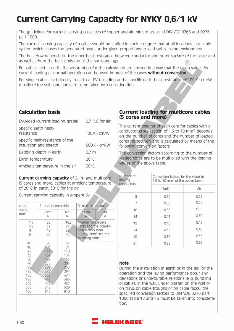
R
Current Carrying Capacity for NYKY 0,6/1 kV
The guidelines for current carrying capacities of copper and aluminium are valid DIN VDE 0265 and 0276part 1000.
The current carrying capacity of a cable should be limited in such a degree that at all locations in a cablesystem which causes the generated heats under given proportions to lead safely in the environment.
The heat flow depends on the inner heat-resistance between conductor and outer surface of the cable andas well as from the heat emission to the surroundings.
For cables laid in earth, the assumption for the calculation are chosen in a way that the given values forcurrent loading at normal operation can be used in most of the cases without conversion.
For single cables laid directly in earth at EVU-Loading and a specific earth heat-resistance of 100 K ? cm/W,mostly of the soil conditions are to be taken into consideration.
Calculation basis
EVU-load (current loading grade) 0,7 (1,0 for air)
Specific earth heat-resistance 100 K ? cm/W
Specific heat-resistance of theinsulation and sheath 600 K ? cm/W
Bedding depth in earth 0,7 m
Earth temperature 208C
Ambient temperature in the air 308C
Current carrying capacity of 3-, 4- and multicore(5 cores and more) cables at ambient temperatureof 208C in earth, 308C for the air.
Current carrying capacity in ampere (A):
cross-sectionmm2
3- and 4-core cable 5- to 61-core cable
EarthA
AirA
EarthA
AirA
1,5 28 18,5 Number of loadingcores and the conver-sion factors from1,5 to 6 mm2 see thefollowing table
2,5 37 274 48 366 60 45
10 80 6216 103 8125 134 11035 162 13450 192 16370 235 20595 283 253
120 323 294150 363 334185 412 386240 478 457300 542 529400 615 610
Current loading for multicore cables(5 cores and more)
The current loading of each core for cables with aconductor cross-section of 1,5 to 10 mm2, dependson the number of cores and the number of loadedcores respectively and is calculated by means of thefollowing conversion factors.
The conversion factors according to the number ofloaded cores are to be multiplied with the loadingvalues of the above table.
Number ofloadingconductors
Conversion factors for the value to1,5 to 10 mm2 of the above table
Earth Air
5 0,70 0,75
7 0,60 0,65
10 0,50 0,55
14 0,45 0,50
19 0,40 0,45
24 0,35 0,40
40 0,30 0,35
61 0,25 0,30
NoteDuring the installation in earth or in the air, for theoperation and the laying performance occur anydeviations or unfavourable relations (e. g. bundlingof cables, in the wall, under plaster, on the wall oron trays, on cable troughs or on cable racks), thespecified conversion factors to DIN VDE 0276 part1000 table 12 and 13 must be taken into considera-tion.
�T 30
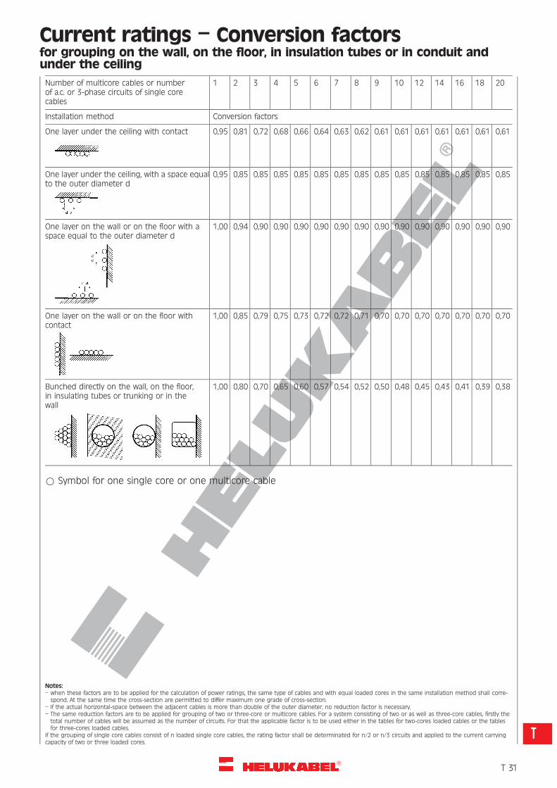
R
Current ratings – Conversion factorsfor grouping on the wall, on the floor, in insulation tubes or in conduit andunder the ceiling
Number of multicore cables or numberof a.c. or 3-phase circuits of single corecables
1 2 3 4 5 6 7 8 9 10 12 14 16 18 20
Installation method Conversion factors
One layer under the ceiling with contact 0,95 0,81 0,72 0,68 0,66 0,64 0,63 0,62 0,61 0,61 0,61 0,61 0,61 0,61 0,61
One layer under the ceiling, with a space equalto the outer diameter d
0,95 0,85 0,85 0,85 0,85 0,85 0,85 0,85 0,85 0,85 0,85 0,85 0,85 0,85 0,85
One layer on the wall or on the floor with aspace equal to the outer diameter d
1,00 0,94 0,90 0,90 0,90 0,90 0,90 0,90 0,90 0,90 0,90 0,90 0,90 0,90 0,90
One layer on the wall or on the floor withcontact
1,00 0,85 0,79 0,75 0,73 0,72 0,72 0,71 0,70 0,70 0,70 0,70 0,70 0,70 0,70
Bunched directly on the wall, on the floor,in insulating tubes or trunking or in thewall
1,00 0,80 0,70 0,65 0,60 0,57 0,54 0,52 0,50 0,48 0,45 0,43 0,41 0,39 0,38
* Symbol for one single core or one multicore cable
Notes:– when these factors are to be applied for the calculation of power ratings, the same type of cables and with equal loaded cores in the same installation method shall corre-spond. At the same time the cross-section are permitted to differ maximum one grade of cross-section.
– If the actual horizontal-space between the adjacent cables is more than double of the outer diameter, no reduction factor is necessary.– The same reduction factors are to be applied for grouping of two or three-core or multicore cables. For a system consisting of two or as well as three-core cables, firstly thetotal number of cables will be assumed as the number of circuits. For that the applicable factor is to be used either in the tables for two-cores loaded cables or the tablesfor three-cores loaded cables.
If the grouping of single core cables consist of n loaded single core cables, the rating factor shall be determinated for n/2 or n/3 circuits and applied to the current carryingcapacity of two or three loaded cores.
�T 31
T
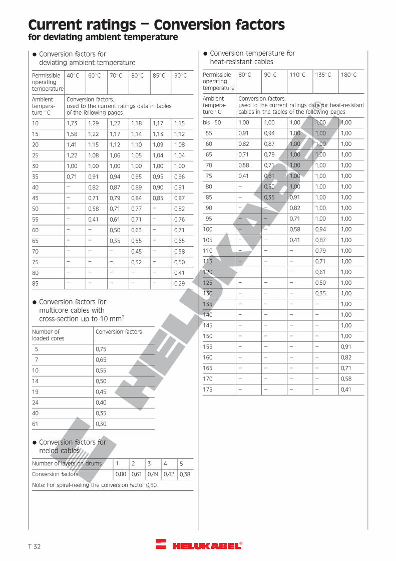
R
Current ratings – Conversion factorsfor deviating ambient temperature
* Conversion factors fordeviating ambient temperature
Permissibleoperatingtemperature
408C 608C 708C 808C 858C 908C
Ambienttempera-ture 8C
Conversion factors,used to the current ratings data in tablesof the following pages
10 1,73 1,29 1,22 1,18 1,17 1,15
15 1,58 1,22 1,17 1,14 1,13 1,12
20 1,41 1,15 1,12 1,10 1,09 1,08
25 1,22 1,08 1,06 1,05 1,04 1,04
30 1,00 1,00 1,00 1,00 1,00 1,00
35 0,71 0,91 0,94 0,95 0,95 0,96
40 – 0,82 0,87 0,89 0,90 0,91
45 – 0,71 0,79 0,84 0,85 0,87
50 – 0,58 0,71 0,77 – 0,82
55 – 0,41 0,61 0,71 – 0,76
60 – – 0,50 0,63 – 0,71
65 – – 0,35 0,55 – 0,65
70 – – – 0,45 – 0,58
75 – – – 0,32 – 0,50
80 – – – – – 0,41
85 – – – – – 0,29
* Conversion factors formulticore cables withcross-section up to 10 mm2
Number ofloaded cores
Conversion factors
5 0,75
7 0,65
10 0,55
14 0,50
19 0,45
24 0,40
40 0,35
61 0,30
* Conversion factors forreeled cables
Number of layers on drums 1 2 3 4 5
Conversion factors 0,80 0,61 0,49 0,42 0,38
Note: For spiral-reeling the conversion factor 0,80.
* Conversion temperature forheat-resistant cables
Permissibleoperatingtemperature
808C 908C 1108C 1358C 1808C
Ambienttempera-ture 8C
Conversion factors,used to the current ratings data for heat-resistantcables in the tables of the following pages
bis 50 1,00 1,00 1,00 1,00 1,00
55 0,91 0,94 1,00 1,00 1,00
60 0,82 0,87 1,00 1,00 1,00
65 0,71 0,79 1,00 1,00 1,00
70 0,58 0,71 1,00 1,00 1,00
75 0,41 0,61 1,00 1,00 1,00
80 – 0,50 1,00 1,00 1,00
85 – 0,35 0,91 1,00 1,00
90 – – 0,82 1,00 1,00
95 – – 0,71 1,00 1,00
100 – – 0,58 0,94 1,00
105 – – 0,41 0,87 1,00
110 – – – 0,79 1,00
115 – – – 0,71 1,00
120 – – – 0,61 1,00
125 – – – 0,50 1,00
130 – – – 0,35 1,00
135 – – – – 1,00
140 – – – – 1,00
145 – – – – 1,00
150 – – – – 1,00
155 – – – – 0,91
160 – – – – 0,82
165 – – – – 0,71
170 – – – – 0,58
175 – – – – 0,41
�T 32
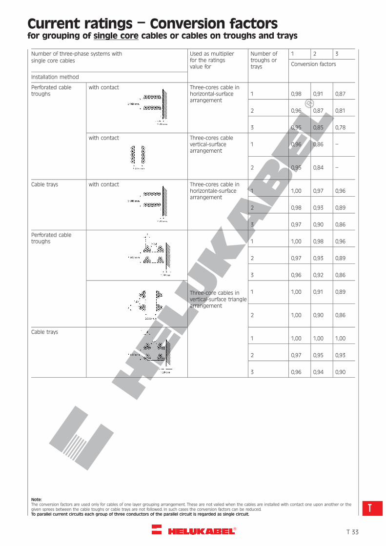
R
Current ratings – Conversion factorsfor grouping of single core cables or cables on troughs and trays
Number of three-phase systems with Used as multiplierfor the ratingsvalue for
Number oftroughs ortrays
1 2 3single core cables
Conversion factors
Installation method
Perforated cabletroughs
with contact Three-cores cable inhorizontal-surfacearrangement
1 0,98 0,91 0,87
2 0,96 0,87 0,81
3 0,95 0,85 0,78
with contact Three-cores cablevertical-surfacearrangement
1 0,96 0,86 –
2 0,95 0,84 –
Cable trays with contact Three-cores cable inhorizontale-surfacearrangement
1 1,00 0,97 0,96
2 0,98 0,93 0,89
3 0,97 0,90 0,86
Perforated cabletroughs
Three-core cables invertical-surface trianglearrangement
1 1,00 0,98 0,96
2 0,97 0,93 0,89
3 0,96 0,92 0,86
1 1,00 0,91 0,89
2 1,00 0,90 0,86
Cable trays1 1,00 1,00 1,00
2 0,97 0,95 0,93
3 0,96 0,94 0,90
Note:The conversion factors are used only for cables of one layer grouping arrangement. These are not valied when the cables are installed with contact one upon another or thegiven sprees between the cable toughs or cable trays are not followed. In such cases the conversion factors can be reduced.To parallel current circuits each group of three conductors of the parallel circuit is regarded as single circuit.
�T 33
T
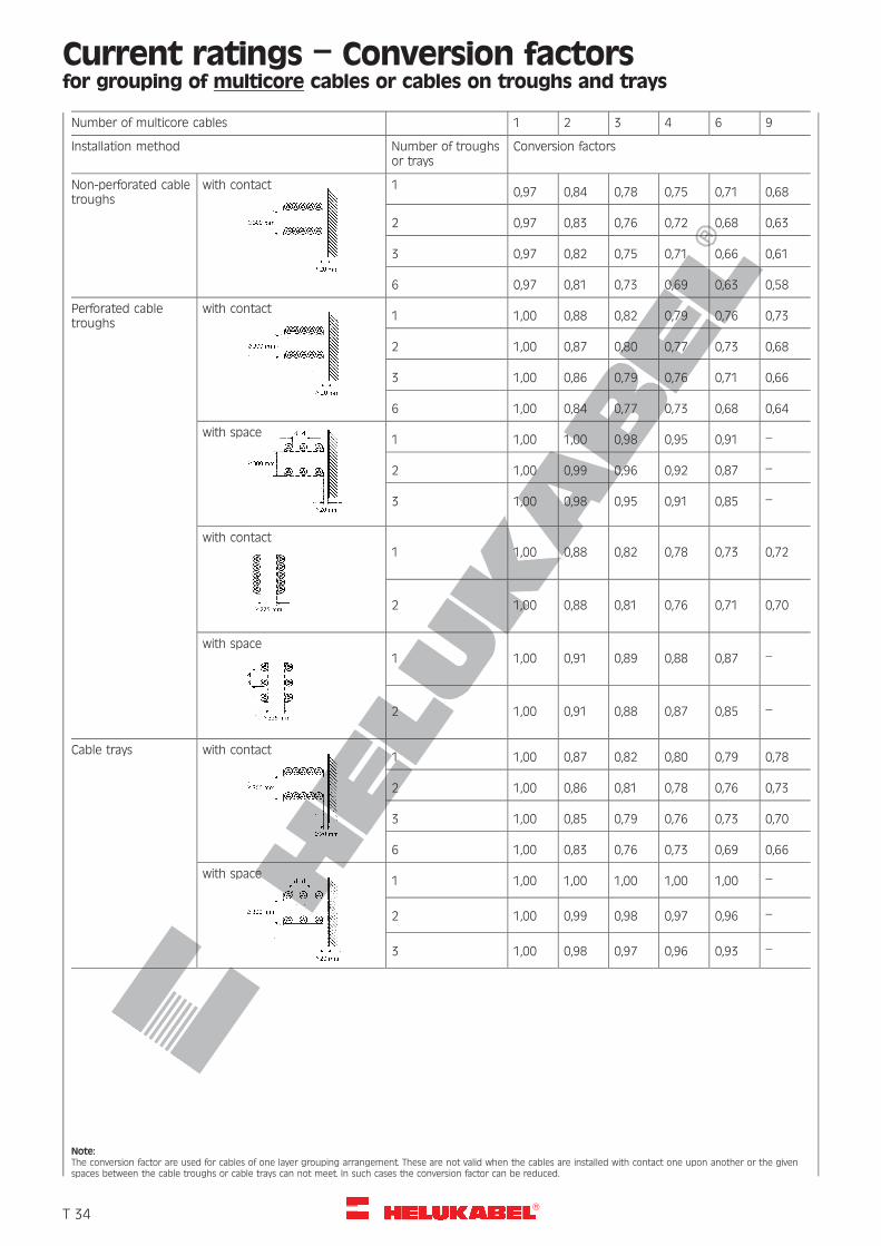
R
Current ratings – Conversion factorsfor grouping of multicore cables or cables on troughs and trays
Number of multicore cables 1 2 3 4 6 9
Installation method Number of troughsor trays
Conversion factors
Non-perforated cabletroughs
with contact 10,97 0,84 0,78 0,75 0,71 0,68
2 0,97 0,83 0,76 0,72 0,68 0,63
3 0,97 0,82 0,75 0,71 0,66 0,61
6 0,97 0,81 0,73 0,69 0,63 0,58
Perforated cabletroughs
with contact1 1,00 0,88 0,82 0,79 0,76 0,73
2 1,00 0,87 0,80 0,77 0,73 0,68
3 1,00 0,86 0,79 0,76 0,71 0,66
6 1,00 0,84 0,77 0,73 0,68 0,64
with space1 1,00 1,00 0,98 0,95 0,91 –
2 1,00 0,99 0,96 0,92 0,87 –
3 1,00 0,98 0,95 0,91 0,85 –
with contact1 1,00 0,88 0,82 0,78 0,73 0,72
2 1,00 0,88 0,81 0,76 0,71 0,70
with space1 1,00 0,91 0,89 0,88 0,87 –
2 1,00 0,91 0,88 0,87 0,85 –
Cable trays with contact1 1,00 0,87 0,82 0,80 0,79 0,78
2 1,00 0,86 0,81 0,78 0,76 0,73
3 1,00 0,85 0,79 0,76 0,73 0,70
6 1,00 0,83 0,76 0,73 0,69 0,66
with space1 1,00 1,00 1,00 1,00 1,00 –
2 1,00 0,99 0,98 0,97 0,96 –
3 1,00 0,98 0,97 0,96 0,93 –
Note:The conversion factor are used for cables of one layer grouping arrangement. These are not valid when the cables are installed with contact one upon another or the givenspaces between the cable troughs or cable trays can not meet. In such cases the conversion factor can be reduced.
�T 34
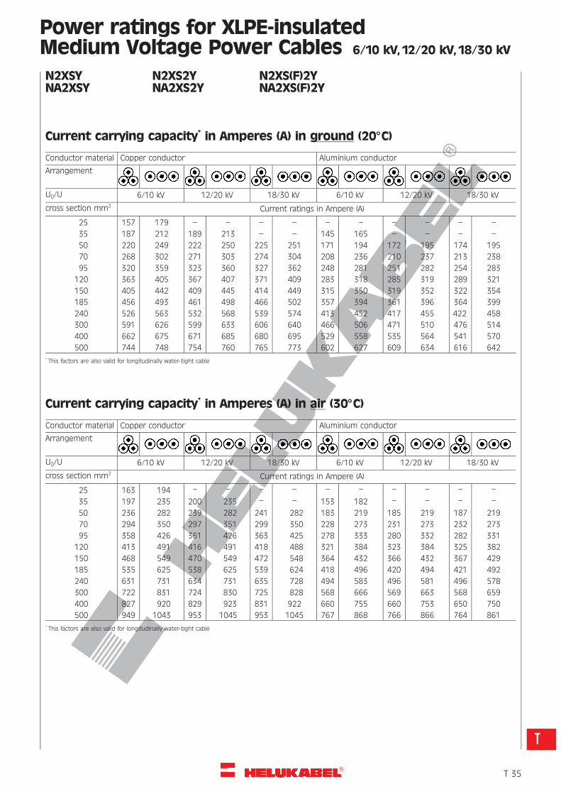
R
Power ratings for XLPE-insulatedMedium Voltage Power Cables 6/10 kV, 12/20 kV, 18/30 kV
N2XSY N2XS2Y N2XS(F)2YNA2XSY NA2XS2Y NA2XS(F)2Y
Current carrying capacity* in Amperes (A) in ground (208C)
Conductor material Copper conductor Aluminium conductor
Arrangement
U0/U 6/10 kV 12/20 kV 18/30 kV 6/10 kV 12/20 kV 18/30 kV
cross section mm2 Current ratings in Ampere (A)
25 157 179 – – – – – – – – – –
35 187 212 189 213 – – 145 165 – – – –
50 220 249 222 250 225 251 171 194 172 195 174 195
70 268 302 271 303 274 304 208 236 210 237 213 238
95 320 359 323 360 327 362 248 281 251 282 254 283
120 363 405 367 407 371 409 283 318 285 319 289 321
150 405 442 409 445 414 449 315 350 319 352 322 354
185 456 493 461 498 466 502 357 394 361 396 364 399
240 526 563 532 568 539 574 413 452 417 455 422 458
300 591 626 599 633 606 640 466 506 471 510 476 514
400 662 675 671 685 680 695 529 558 535 564 541 570
500 744 748 754 760 765 773 602 627 609 634 616 642* This factors are also valid for longitudinally water-tight cable
Current carrying capacity* in Amperes (A) in air (308C)
Conductor material Copper conductor Aluminium conductor
Arrangement
U0/U 6/10 kV 12/20 kV 18/30 kV 6/10 kV 12/20 kV 18/30 kV
cross section mm2 Current ratings in Ampere (A)
25 163 194 – – – – – – – – – –
35 197 235 200 235 – – 153 182 – – – –
50 236 282 239 282 241 282 183 219 185 219 187 219
70 294 350 297 351 299 350 228 273 231 273 232 273
95 358 426 361 426 363 425 278 333 280 332 282 331
120 413 491 416 491 418 488 321 384 323 384 325 382
150 468 549 470 549 472 548 364 432 366 432 367 429
185 535 625 538 625 539 624 418 496 420 494 421 492
240 631 731 634 731 635 728 494 583 496 581 496 578
300 722 831 724 830 725 828 568 666 569 663 568 659
400 827 920 829 923 831 922 660 755 660 753 650 750
500 949 1043 953 1045 953 1045 767 868 766 866 764 861* This factors are also valid for longitudinally water-tight cable
�T 35
T
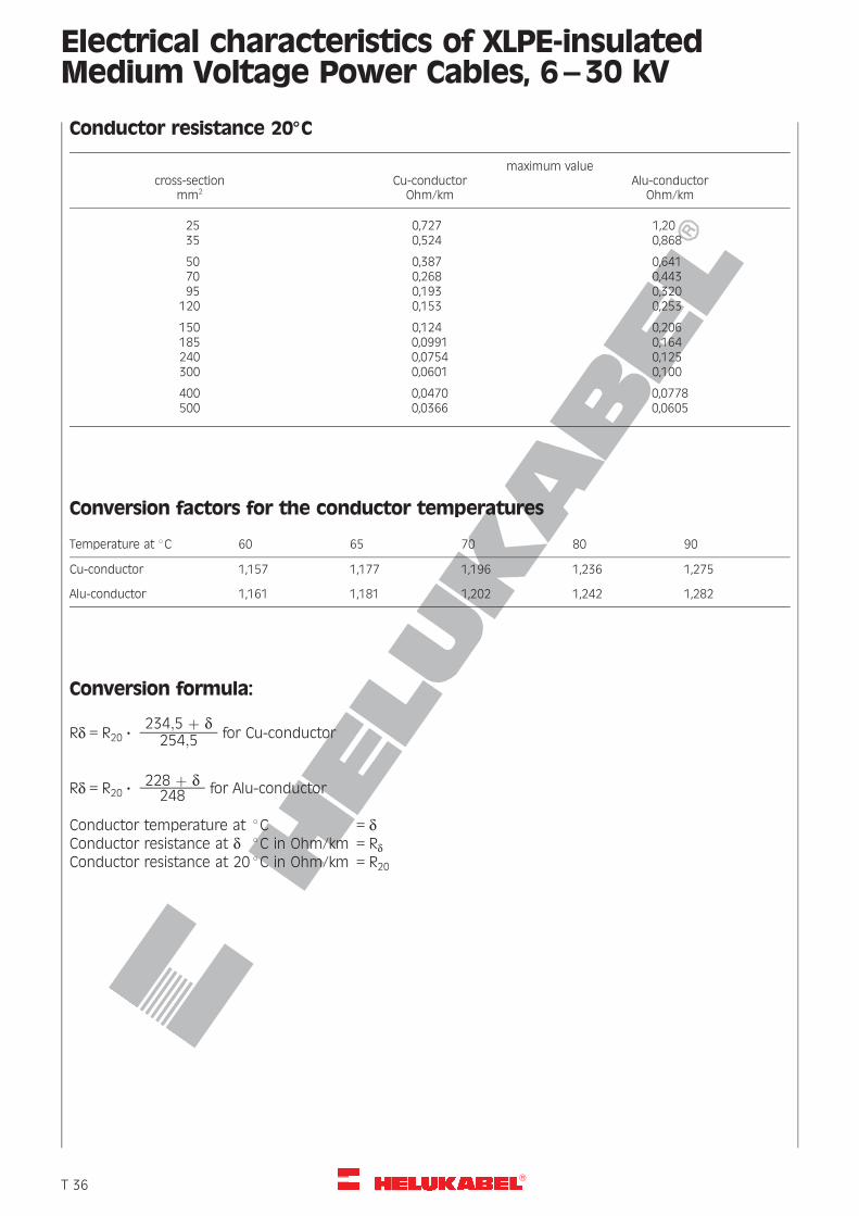
R
Electrical characteristics of XLPE-insulatedMedium Voltage Power Cables, 6–30 kV
Conductor resistance 208C
maximum valuecross-section
mm2Cu-conductor
Ohm/kmAlu-conductor
Ohm/km
25 0,727 1,2035 0,524 0,868
50 0,387 0,64170 0,268 0,44395 0,193 0,320
120 0,153 0,253
150 0,124 0,206185 0,0991 0,164240 0,0754 0,125300 0,0601 0,100
400 0,0470 0,0778500 0,0366 0,0605
Conversion factors for the conductor temperatures
Temperature at 8C 60 65 70 80 90
Cu-conductor 1,157 1,177 1,196 1,236 1,275
Alu-conductor 1,161 1,181 1,202 1,242 1,282
Conversion formula:
Rd = R20 ?234;5 þ d254;5 for Cu-conductor
Rd = R20 ?228 þ d248 for Alu-conductor
Conductor temperature at 8C = dConductor resistance at d 8C in Ohm/km = RdConductor resistance at 20 8C in Ohm/km = R20
�T 36
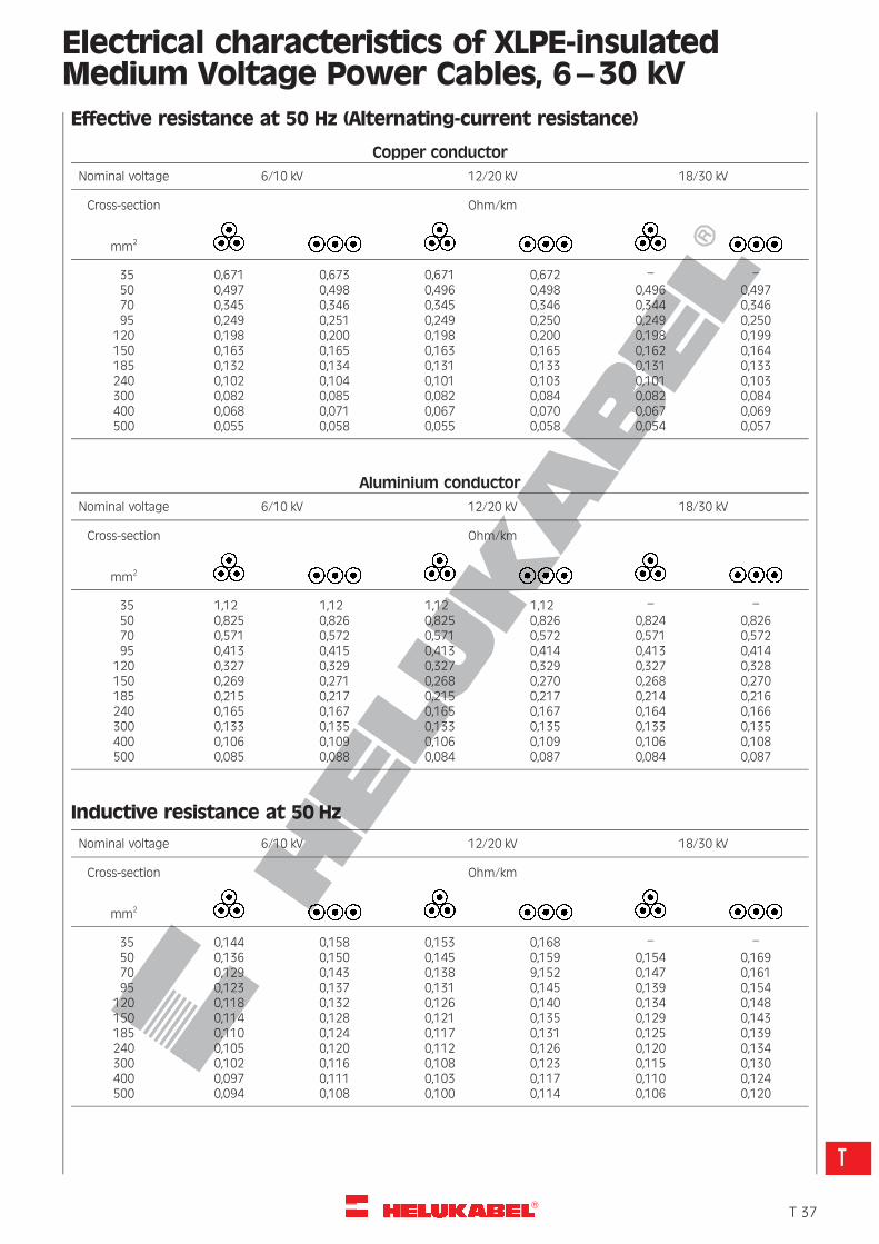
R
Electrical characteristics of XLPE-insulatedMedium Voltage Power Cables, 6–30 kVEffective resistance at 50 Hz (Alternating-current resistance)
Copper conductor
Nominal voltage 6/10 kV 12/20 kV 18/30 kV
Cross-section Ohm/km
mm2
35 0,671 0,673 0,671 0,672 – –50 0,497 0,498 0,496 0,498 0,496 0,49770 0,345 0,346 0,345 0,346 0,344 0,34695 0,249 0,251 0,249 0,250 0,249 0,250
120 0,198 0,200 0,198 0,200 0,198 0,199150 0,163 0,165 0,163 0,165 0,162 0,164185 0,132 0,134 0,131 0,133 0,131 0,133240 0,102 0,104 0,101 0,103 0,101 0,103300 0,082 0,085 0,082 0,084 0,082 0,084400 0,068 0,071 0,067 0,070 0,067 0,069500 0,055 0,058 0,055 0,058 0,054 0,057
Aluminium conductor
Nominal voltage 6/10 kV 12/20 kV 18/30 kV
Cross-section Ohm/km
mm2
35 1,12 1,12 1,12 1,12 – –50 0,825 0,826 0,825 0,826 0,824 0,82670 0,571 0,572 0,571 0,572 0,571 0,57295 0,413 0,415 0,413 0,414 0,413 0,414
120 0,327 0,329 0,327 0,329 0,327 0,328150 0,269 0,271 0,268 0,270 0,268 0,270185 0,215 0,217 0,215 0,217 0,214 0,216240 0,165 0,167 0,165 0,167 0,164 0,166300 0,133 0,135 0,133 0,135 0,133 0,135400 0,106 0,109 0,106 0,109 0,106 0,108500 0,085 0,088 0,084 0,087 0,084 0,087
Inductive resistance at 50 Hz
Nominal voltage 6/10 kV 12/20 kV 18/30 kV
Cross-section Ohm/km
mm2
35 0,144 0,158 0,153 0,168 – –50 0,136 0,150 0,145 0,159 0,154 0,16970 0,129 0,143 0,138 9,152 0,147 0,16195 0,123 0,137 0,131 0,145 0,139 0,154
120 0,118 0,132 0,126 0,140 0,134 0,148150 0,114 0,128 0,121 0,135 0,129 0,143185 0,110 0,124 0,117 0,131 0,125 0,139240 0,105 0,120 0,112 0,126 0,120 0,134300 0,102 0,116 0,108 0,123 0,115 0,130400 0,097 0,111 0,103 0,117 0,110 0,124500 0,094 0,108 0,100 0,114 0,106 0,120
�T 37
T
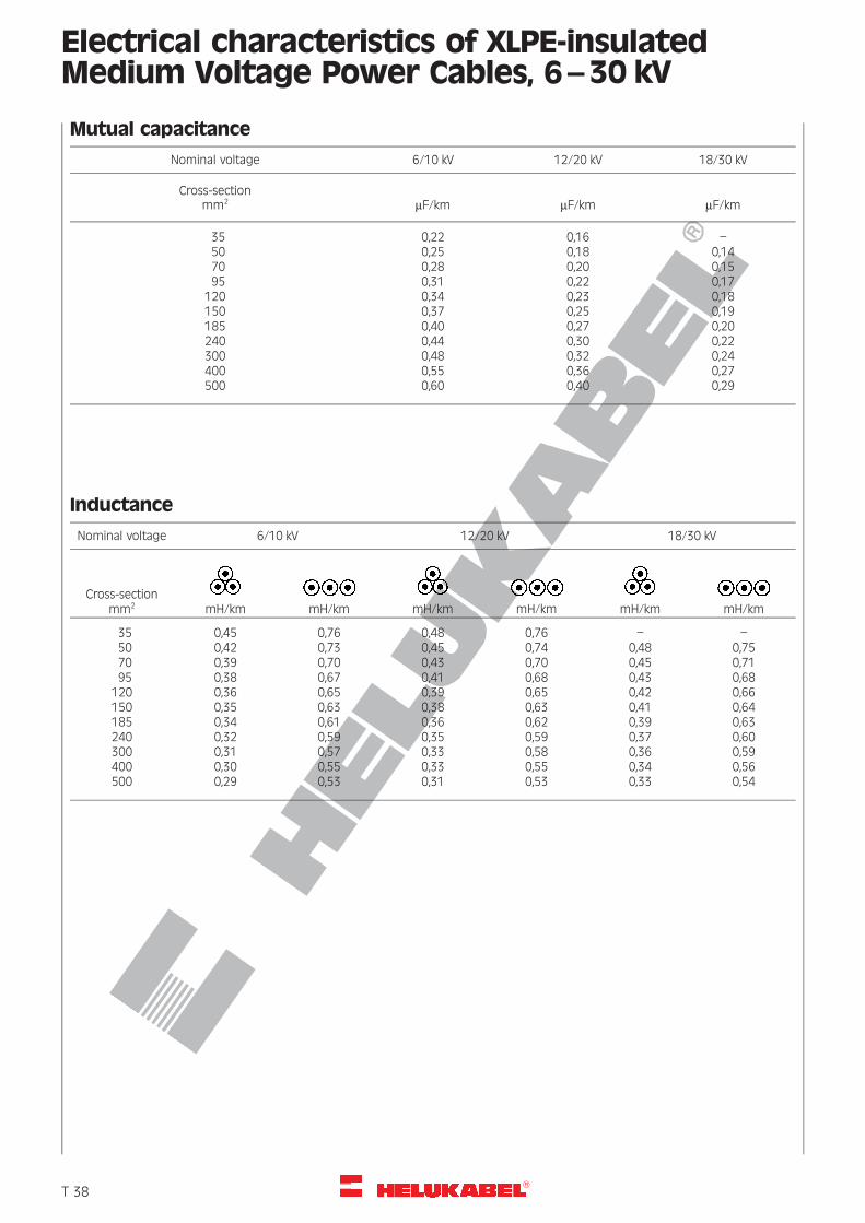
R
Electrical characteristics of XLPE-insulatedMedium Voltage Power Cables, 6–30 kV
Mutual capacitance
Nominal voltage 6/10 kV 12/20 kV 18/30 kV
Cross-sectionmm2 mF/km mF/km mF/km
35 0,22 0,16 –50 0,25 0,18 0,1470 0,28 0,20 0,1595 0,31 0,22 0,17
120 0,34 0,23 0,18150 0,37 0,25 0,19185 0,40 0,27 0,20240 0,44 0,30 0,22300 0,48 0,32 0,24400 0,55 0,36 0,27500 0,60 0,40 0,29
Inductance
Nominal voltage 6/10 kV 12/20 kV 18/30 kV
Cross-sectionmm2 mH/km mH/km mH/km mH/km mH/km mH/km
35 0,45 0,76 0,48 0,76 – –50 0,42 0,73 0,45 0,74 0,48 0,7570 0,39 0,70 0,43 0,70 0,45 0,7195 0,38 0,67 0,41 0,68 0,43 0,68
120 0,36 0,65 0,39 0,65 0,42 0,66150 0,35 0,63 0,38 0,63 0,41 0,64185 0,34 0,61 0,36 0,62 0,39 0,63240 0,32 0,59 0,35 0,59 0,37 0,60300 0,31 0,57 0,33 0,58 0,36 0,59400 0,30 0,55 0,33 0,55 0,34 0,56500 0,29 0,53 0,31 0,53 0,33 0,54
�T 38
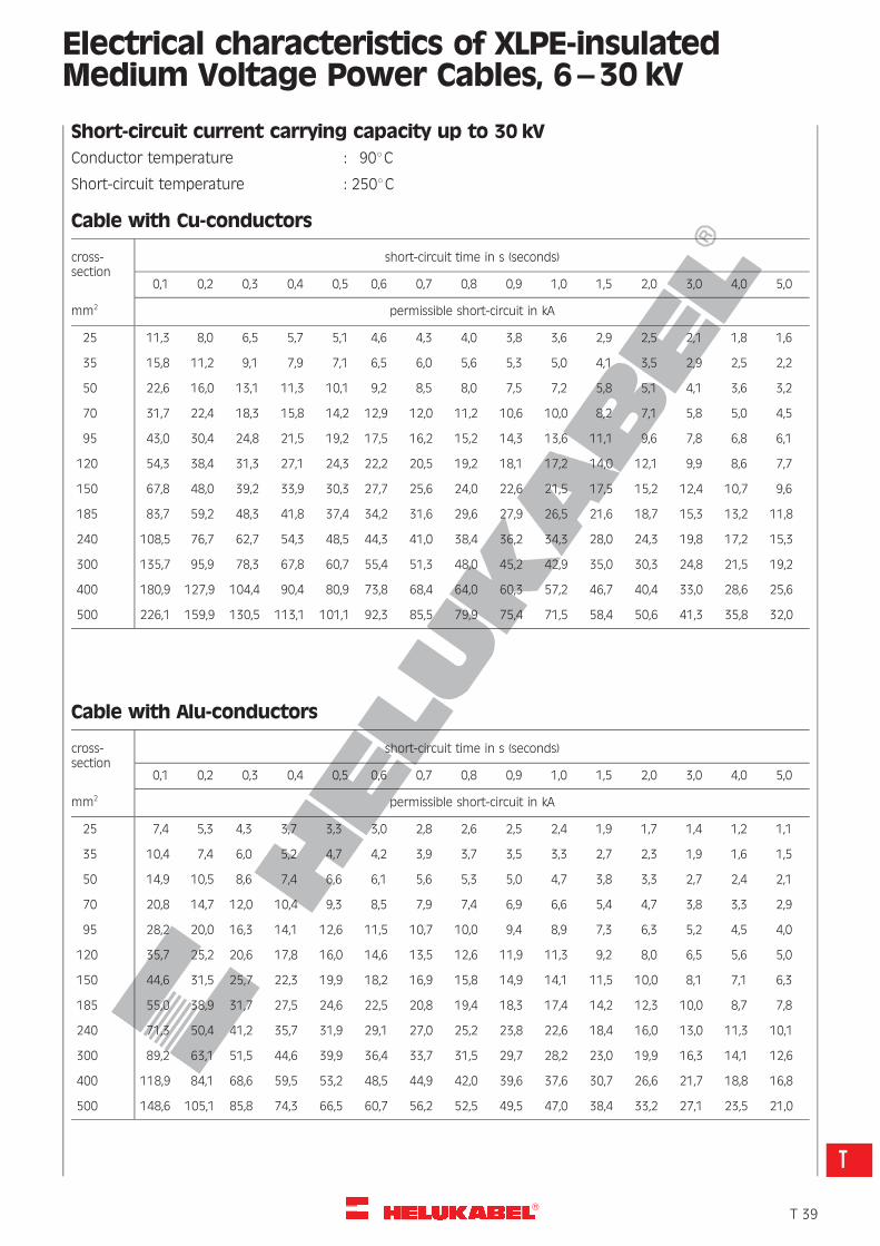
R
Electrical characteristics of XLPE-insulatedMedium Voltage Power Cables, 6–30 kV
Short-circuit current carrying capacity up to 30 kV
Conductor temperature : 908C
Short-circuit temperature : 2508C
Cable with Cu-conductors
cross-section
mm2
short-circuit time in s (seconds)
0,1 0,2 0,3 0,4 0,5 0,6 0,7 0,8 0,9 1,0 1,5 2,0 3,0 4,0 5,0
permissible short-circuit in kA
25 11,3 8,0 6,5 5,7 5,1 4,6 4,3 4,0 3,8 3,6 2,9 2,5 2,1 1,8 1,6
35 15,8 11,2 9,1 7,9 7,1 6,5 6,0 5,6 5,3 5,0 4,1 3,5 2,9 2,5 2,2
50 22,6 16,0 13,1 11,3 10,1 9,2 8,5 8,0 7,5 7,2 5,8 5,1 4,1 3,6 3,2
70 31,7 22,4 18,3 15,8 14,2 12,9 12,0 11,2 10,6 10,0 8,2 7,1 5,8 5,0 4,5
95 43,0 30,4 24,8 21,5 19,2 17,5 16,2 15,2 14,3 13,6 11,1 9,6 7,8 6,8 6,1
120 54,3 38,4 31,3 27,1 24,3 22,2 20,5 19,2 18,1 17,2 14,0 12,1 9,9 8,6 7,7
150 67,8 48,0 39,2 33,9 30,3 27,7 25,6 24,0 22,6 21,5 17,5 15,2 12,4 10,7 9,6
185 83,7 59,2 48,3 41,8 37,4 34,2 31,6 29,6 27,9 26,5 21,6 18,7 15,3 13,2 11,8
240 108,5 76,7 62,7 54,3 48,5 44,3 41,0 38,4 36,2 34,3 28,0 24,3 19,8 17,2 15,3
300 135,7 95,9 78,3 67,8 60,7 55,4 51,3 48,0 45,2 42,9 35,0 30,3 24,8 21,5 19,2
400 180,9 127,9 104,4 90,4 80,9 73,8 68,4 64,0 60,3 57,2 46,7 40,4 33,0 28,6 25,6
500 226,1 159,9 130,5 113,1 101,1 92,3 85,5 79,9 75,4 71,5 58,4 50,6 41,3 35,8 32,0
Cable with Alu-conductors
cross-section
mm2
short-circuit time in s (seconds)
0,1 0,2 0,3 0,4 0,5 0,6 0,7 0,8 0,9 1,0 1,5 2,0 3,0 4,0 5,0
permissible short-circuit in kA
25 7,4 5,3 4,3 3,7 3,3 3,0 2,8 2,6 2,5 2,4 1,9 1,7 1,4 1,2 1,1
35 10,4 7,4 6,0 5,2 4,7 4,2 3,9 3,7 3,5 3,3 2,7 2,3 1,9 1,6 1,5
50 14,9 10,5 8,6 7,4 6,6 6,1 5,6 5,3 5,0 4,7 3,8 3,3 2,7 2,4 2,1
70 20,8 14,7 12,0 10,4 9,3 8,5 7,9 7,4 6,9 6,6 5,4 4,7 3,8 3,3 2,9
95 28,2 20,0 16,3 14,1 12,6 11,5 10,7 10,0 9,4 8,9 7,3 6,3 5,2 4,5 4,0
120 35,7 25,2 20,6 17,8 16,0 14,6 13,5 12,6 11,9 11,3 9,2 8,0 6,5 5,6 5,0
150 44,6 31,5 25,7 22,3 19,9 18,2 16,9 15,8 14,9 14,1 11,5 10,0 8,1 7,1 6,3
185 55,0 38,9 31,7 27,5 24,6 22,5 20,8 19,4 18,3 17,4 14,2 12,3 10,0 8,7 7,8
240 71,3 50,4 41,2 35,7 31,9 29,1 27,0 25,2 23,8 22,6 18,4 16,0 13,0 11,3 10,1
300 89,2 63,1 51,5 44,6 39,9 36,4 33,7 31,5 29,7 28,2 23,0 19,9 16,3 14,1 12,6
400 118,9 84,1 68,6 59,5 53,2 48,5 44,9 42,0 39,6 37,6 30,7 26,6 21,7 18,8 16,8
500 148,6 105,1 85,8 74,3 66,5 60,7 56,2 52,5 49,5 47,0 38,4 33,2 27,1 23,5 21,0
�T 39
T
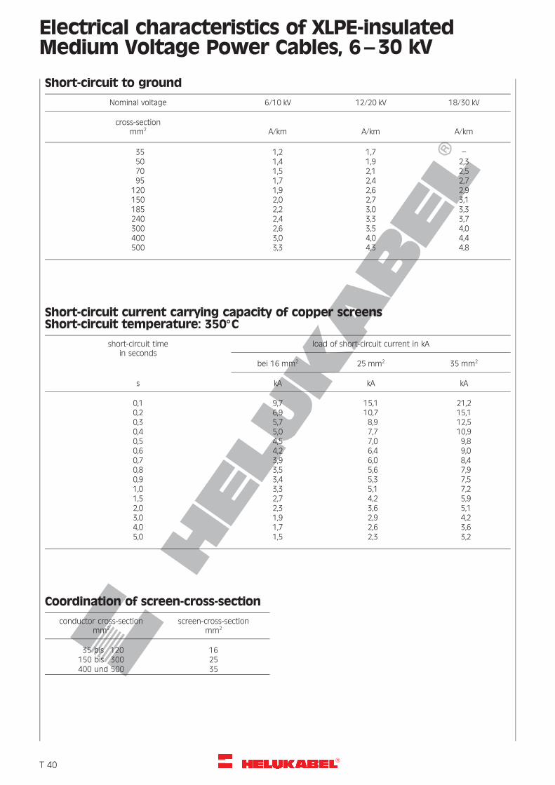
R
Electrical characteristics of XLPE-insulatedMedium Voltage Power Cables, 6–30 kV
Short-circuit to ground
Nominal voltage 6/10 kV 12/20 kV 18/30 kV
cross-sectionmm2 A/km A/km A/km
35 1,2 1,7 –50 1,4 1,9 2,370 1,5 2,1 2,595 1,7 2,4 2,7
120 1,9 2,6 2,9150 2,0 2,7 3,1185 2,2 3,0 3,3240 2,4 3,3 3,7300 2,6 3,5 4,0400 3,0 4,0 4,4500 3,3 4,3 4,8
Short-circuit current carrying capacity of copper screensShort-circuit temperature: 3508C
short-circuit timein seconds
load of short-circuit current in kA
bei 16 mm2 25 mm2 35 mm2
s kA kA kA
0,1 9,7 15,1 21,20,2 6,9 10,7 15,10,3 5,7 8,9 12,50,4 5,0 7,7 10,90,5 4,5 7,0 9,80,6 4,2 6,4 9,00,7 3,9 6,0 8,40,8 3,5 5,6 7,90,9 3,4 5,3 7,51,0 3,3 5,1 7,21,5 2,7 4,2 5,92,0 2,3 3,6 5,13,0 1,9 2,9 4,24,0 1,7 2,6 3,65,0 1,5 2,3 3,2
Coordination of screen-cross-section
conductor cross-sectionmm2
screen-cross-sectionmm2
35 bis 120 16150 bis 300 25400 und 500 35
�T 40
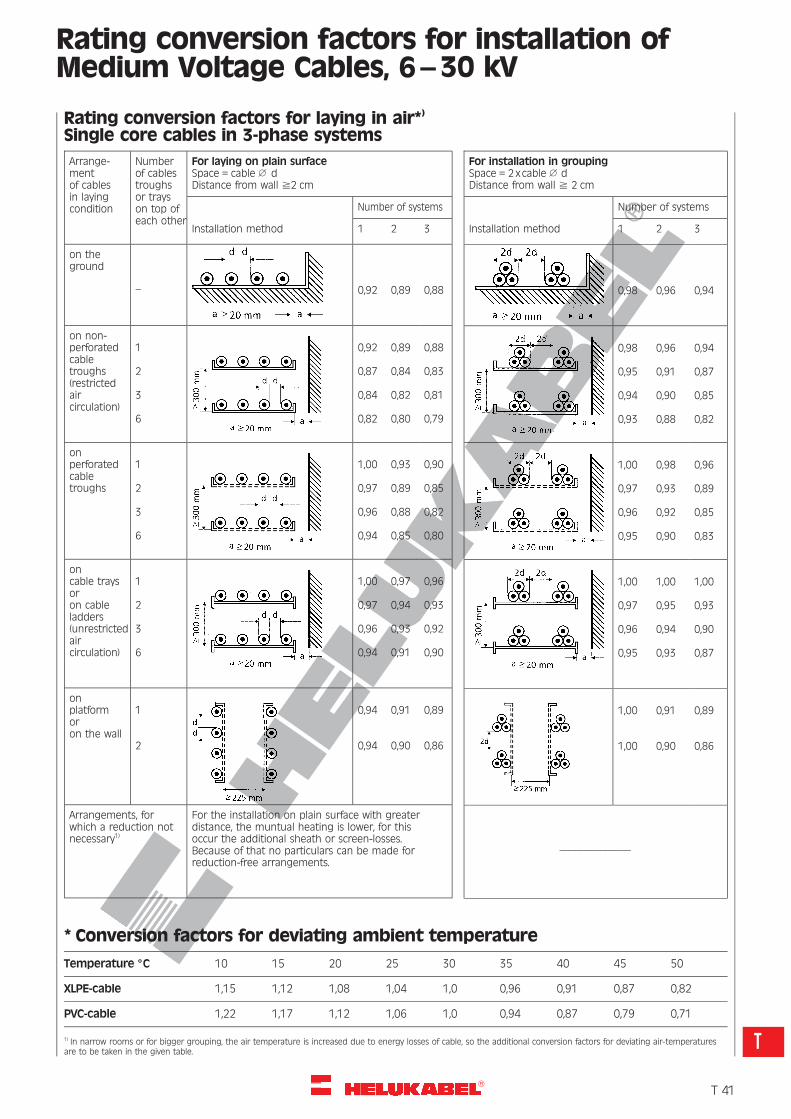
R
Rating conversion factors for installation ofMedium Voltage Cables, 6–30 kV
Rating conversion factors for laying in air*)
Single core cables in 3-phase systems
Arrange-mentof cablesin layingcondition
Numberof cablestroughsor trayson top ofeach other
For laying on plain surfaceSpace = cable 1 dDistance from wall ^2 cm
Number of systems
Installation method 1 2 3
on theground
– 0,92 0,89 0,88
on non-perforatedcabletroughs(restrictedaircirculation)
1
2
3
6
0,92
0,87
0,84
0,82
0,89
0,84
0,82
0,80
0,88
0,83
0,81
0,79
onperforatedcabletroughs
1
2
3
6
1,00
0,97
0,96
0,94
0,93
0,89
0,88
0,85
0,90
0,85
0,82
0,80
oncable traysoron cableladders(unrestrictedaircirculation)
1
2
3
6
1,00
0,97
0,96
0,94
0,97
0,94
0,93
0,91
0,96
0,93
0,92
0,90
onplatformoron the wall
1
2
0,94
0,94
0,91
0,90
0,89
0,86
Arrangements, forwhich a reduction notnecessary1)
For the installation on plain surface with greaterdistance, the muntual heating is lower, for thisoccur the additional sheath or screen-losses.Because of that no particulars can be made forreduction-free arrangements.
For installation in groupingSpace = 2xcable 1 dDistance from wall ^ 2 cm
Number of systems
Installation method 1 2 3
0,98 0,96 0,94
0,98
0,95
0,94
0,93
0,96
0,91
0,90
0,88
0,94
0,87
0,85
0,82
1,00
0,97
0,96
0,95
0,98
0,93
0,92
0,90
0,96
0,89
0,85
0,83
1,00
0,97
0,96
0,95
1,00
0,95
0,94
0,93
1,00
0,93
0,90
0,87
1,00
1,00
0,91
0,90
0,89
0,86
––––––––––––––
* Conversion factors for deviating ambient temperature
Temperature 8C 10 15 20 25 30 35 40 45 50
XLPE-cable 1,15 1,12 1,08 1,04 1,0 0,96 0,91 0,87 0,82
PVC-cable 1,22 1,17 1,12 1,06 1,0 0,94 0,87 0,79 0,71
1) In narrow rooms or for bigger grouping, the air temperature is increased due to energy losses of cable, so the additional conversion factors for deviating air-temperaturesare to be taken in the given table.
�T 41
T
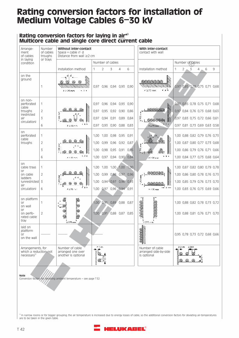
R
Rating conversion factors for installation ofMedium Voltage Cables 6–30 kV
Rating conversion factors for laying in air*)
Multicore cable and single core direct current cable
Arrange-mentof cablesin layingcondition
Numberof cablestroughsor trays
Without inter-contactSpace = cable 1 dDistance from wall ^2 cm
Number of cables
Installation method 1 2 3 4 6
on theground
1 0,97 0,96 0,94 0,93 0,90
on non-perforatedcabletroughs(restrictedaircirculation)
1
2
3
6
0,97
0,97
0,97
0,97
0,96
0,95
0,94
0,93
0,94
0,92
0,91
0,90
0,93
0,90
0,89
0,88
0,90
0,86
0,84
0,83
onperforatedcabletroughs
1
2
3
6
1,00
1,00
1,00
1,00
1,00
0,99
0,98
0,97
0,98
0,96
0,95
0,94
0,95
0,92
0,91
0,90
0,91
0,87
0,85
0,84
oncable traysoron cableladders(unrestrictedaircirculation)
1
2
3
6
1,00
1,00
1,00
1,00
1,00
0,99
0,94
0,97
1,00
0,98
0,97
0,96
1,00
0,97
0,96
0,94
1,00
0,96
0,93
0,91
on platformoron walloron perfo-rated cabletray
1
2
1,00
1,00
0,91
0,91
0,89
0,88
0,88
0,87
0,87
0,85
laid onplatformoron the wall
–––––– –––––– ––––––
Arrangements, forwhich a reduction notnecessary1)
Number of cablearranged one overanother is optional
With inter-contactcontact with wall
Number of cables
Installation method 1 2 3 4 6 9
0,97 0,85 0,78 0,75 0,71 0,68
0,97
0,97
0,97
0,97
0,85
0,84
0,83
0,81
0,78
0,76
0,75
0,73
0,75
0,73
0,72
0,69
0,71
0,68
0,66
0,63
0,68
0,63
0,61
0,58
1,00
1,00
1,00
1,00
0,88
0,87
0,86
0,84
0,82
0,80
0,79
0,77
0,79
0,77
0,76
0,73
0,76
0,73
0,71
0,68
0,73
0,68
0,66
0,64
1,00
1,00
1,00
1,00
0,87
0,86
0,85
0,83
0,82
0,80
0,79
0,76
0,80
0,78
0,76
0,73
0,79
0,76
0,73
0,69
0,78
0,73
0,70
0,66
1,00
1,00
0,88
0,88
0,82
0,81
0,78
0,76
0,73
0,71
0,72
0,70
0,95 0,78 0,73 0,72 0,68 0,66
Number of cablearranged side-by-sideis optional
NoteConversion factors for deviating ambient temperature – see page T32
1) In narrow rooms or for bigger grouping, the air temperature is increased due to energy losses of cable, so the additional conversion factors for deviating air-temperaturesare to be taken in the given table.
�T 42
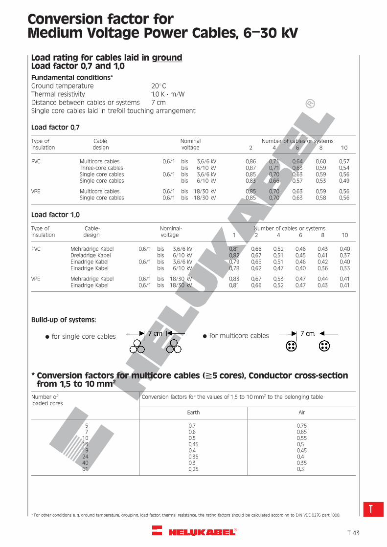
R
Conversion factor forMedium Voltage Power Cables, 6–30 kV
Load rating for cables laid in groundLoad factor 0,7 and 1,0
Fundamental conditions*Ground temperature 208CThermal resistivity 1,0 K ? m/WDistance between cables or systems 7 cmSingle core cables laid in trefoil touching arrangement
Load factor 0,7
Type ofinsulation
Cabledesign
Nominalvoltage
Number of cables or systems2 4 6 8 10
PVC Multicore cablesThree-core cablesSingle core cablesSingle core cables
0,6/1 bis 3,6/6 kVbis 6/10 kV
0,6/1 bis 3,6/6 kVbis 6/10 kV
0,860,870,850,83
0,710,710,700,66
0,640,630,630,57
0,600,590,590,53
0,570,540,560,49
VPE Multicore cablesSingle core cables
0,6/1 bis 18/30 kV0,6/1 bis 18/30 kV
0,850,85
0,700,70
0,630,63
0,590,58
0,560,56
Load factor 1,0
Type ofinsulation
Cable-design
Nominal-voltage
Number of cables or systems1 2 4 6 8 10
PVC Mehradrige KabelDreiadrige KabelEinadrige KabelEinadrige Kabel
0,6/1 bis 3,6/6 kVbis 6/10 kV
0,6/1 bis 3,6/6 kVbis 6/10 kV
0,810,820,790,78
0,660,670,650,62
0,520,510,510,47
0,460,450,460,40
0,430,410,420,36
0,400,370,400,33
VPE Mehradrige KabelEinadrige Kabel
0,6/1 bis 18/30 kV0,6/1 bis 18/30 kV
0,830,81
0,670,66
0,530,52
0,470,47
0,440,43
0,410,41
Build-up of systems:
* for single core cables * for multicore cables
* Conversion factors for multicore cables (^5 cores), Conductor cross-sectionfrom 1,5 to 10 mm2
Number ofloaded cores
Conversion factors for the values of 1,5 to 10 mm2 to the belonging table
Earth Air
5 0,7 0,757 0,6 0,65
10 0,5 0,5514 0,45 0,519 0,4 0,4524 0,35 0,440 0,3 0,3561 0,25 0,3
* For other conditions e. g. ground temperature, grouping, load factor, thermal resistance, the rating factors should be calculated according to DIN VDE 0276 part 1000.
�T 43
T
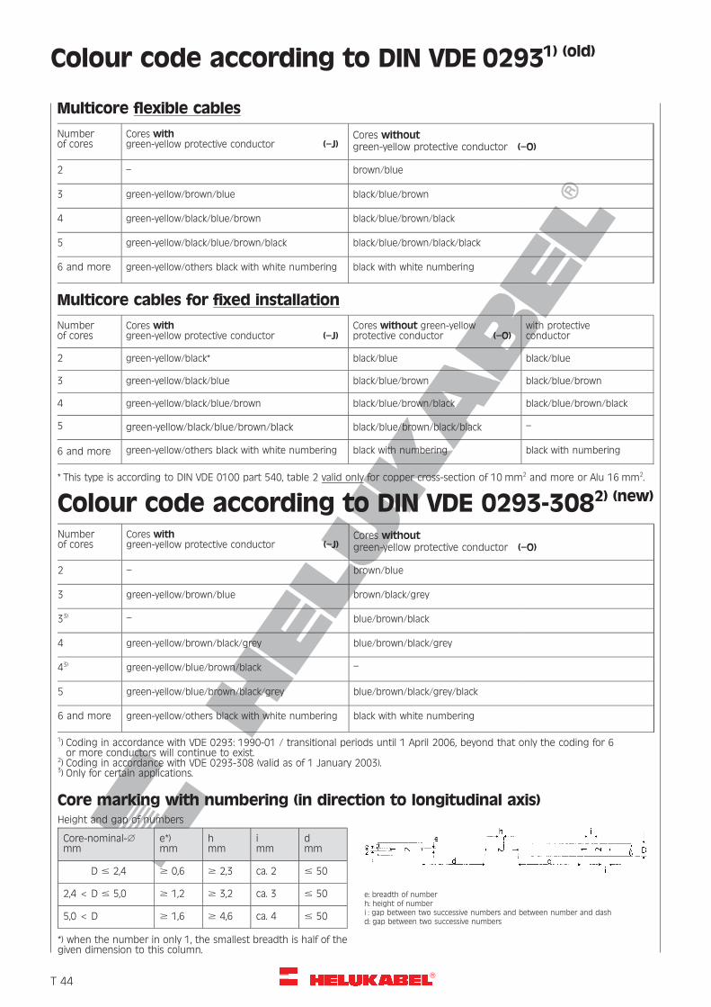
R
Colour code according to DIN VDE 02931) (old)
Multicore flexible cables
Numberof cores
Cores withgreen-yellow protective conductor (–J)
Cores withoutgreen-yellow protective conductor (–O)
2 – brown/blue
3 green-yellow/brown/blue black/blue/brown
4 green-yellow/black/blue/brown black/blue/brown/black
5 green-yellow/black/blue/brown/black black/blue/brown/black/black
6 and more green-yellow/others black with white numbering black with white numbering
Multicore cables for fixed installation
Numberof cores
Cores withgreen-yellow protective conductor (–J)
Cores without green-yellowprotective conductor (–O)
with protectiveconductor
2 green-yellow/black* black/blue black/blue
3 green-yellow/black/blue black/blue/brown black/blue/brown
4 green-yellow/black/blue/brown black/blue/brown/black black/blue/brown/black
5 green-yellow/black/blue/brown/black black/blue/brown/black/black –
6 and more green-yellow/others black with white numbering black with numbering black with numbering
* This type is according to DIN VDE 0100 part 540, table 2 valid only for copper cross-section of 10 mm2 and more or Alu 16 mm2.
Colour code according to DIN VDE 0293-3082) (new)
Numberof cores
Cores withgreen-yellow protective conductor (–J)
Cores withoutgreen-yellow protective conductor (–O)
2 – brown/blue
3 green-yellow/brown/blue brown/black/grey
33) – blue/brown/black
4 green-yellow/brown/black/grey blue/brown/black/grey
43) green-yellow/blue/brown/black –
5 green-yellow/blue/brown/black/grey blue/brown/black/grey/black
6 and more green-yellow/others black with white numbering black with white numbering
1) Coding in accordance with VDE 0293: 1990-01 / transitional periods until 1 April 2006, beyond that only the coding for 6or more conductors will continue to exist.
2) Coding in accordance with VDE 0293-308 (valid as of 1 January 2003).3) Only for certain applications.
Core marking with numbering (in direction to longitudinal axis)Height and gap of numbers
Core-nominal-1mm
e*)mm
hmm
imm
dmm
D # 2,4 $ 0,6 $ 2,3 ca. 2 # 50
2,4 < D # 5,0 $ 1,2 $ 3,2 ca. 3 # 50
5,0 < D $ 1,6 $ 4,6 ca. 4 # 50
*) when the number in only 1, the smallest breadth is half of thegiven dimension to this column.
e: breadth of numberh: height of numberi : gap between two successive numbers and between number and dashd: gap between two successive numbers
�T 44
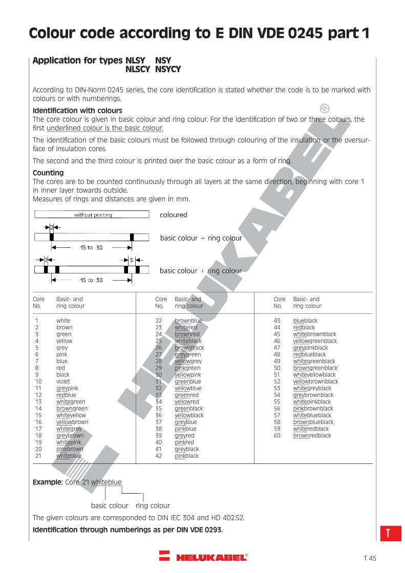
R
Colour code according to E DIN VDE 0245 part 1
Application for types NLSY NSYNLSCY NSYCY
According to DIN-Norm 0245 series, the core identification is stated whether the code is to be marked withcolours or with numberings.
Identification with coloursThe core colour is given in basic colour and ring colour. For the identification of two or three colours, thefirst underlined colour is the basic colour.
The identification of the basic colours must be followed through colouring of the insulation or the oversur-face of insulation cores.
The second and the third colour is printed over the basic colour as a form of ring.
CountingThe cores are to be counted continuously through all layers at the same direction, beginning with core 1in inner layer towards outside.Measures of rings and distances are given in mm.
CoreNo.
Basic- andring colour
CoreNo.
Basic- andring colour
CoreNo.
Basic- andring colour
123456789101112131415161718192021
whitebrowngreenyellowgreypinkblueredblackvioletgreypinkredbluewhitegreenbrowngreenwhiteyellowyellowbrownwhitegreygreybrownwhitepinkpinkbrownwhiteblue
222324252627282930313233343536373839404142
brownbluewhiteredbrownredwhiteblackbrownblackgreygreenyellowgreypinkgreenyellowpinkgreenblueyellowbluegreenredyellowredgreenblackyellowblackgreybluepinkbluegreyredpinkredgreyblackpinkblack
434445464748495051525354555657585960
blueblackredblackwhitebrownblackyellowgreenblackgreypinkblackredblueblackwhitegreenblackbrowngreenblackwhiteyellowblackyellowbrownblackwhitegreyblackgreybrownblackwhitepinkblackpinkbrownblackwhiteblueblackbrownblueblackwhiteredblackbrownredblack
Example: Core 21whiteblue� ‰� ‰
basic colour ring colour
The given colours are corresponded to DIN IEC 304 and HD 402.S2.
Identification through numberings as per DIN VDE 0293.
�T 45
T
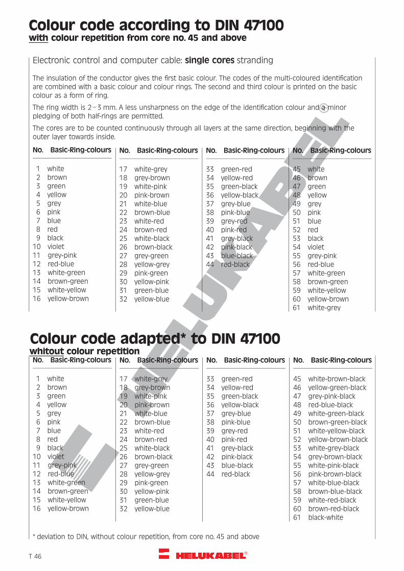
R
Colour code according to DIN 47100with colour repetition from core no. 45 and above
Electronic control and computer cable: single cores stranding
The insulation of the conductor gives the first basic colour. The codes of the multi-coloured identificationare combined with a basic colour and colour rings. The second and third colour is printed on the basiccolour as a form of ring.
The ring width is 2–3 mm. A less unsharpness on the edge of the identification colour and a minorpledging of both half-rings are permitted.
The cores are to be counted continuously through all layers at the same direction, beginning with theouter layer towards inside.
No. Basic-Ring-colours
1 white2 brown3 green4 yellow5 grey6 pink7 blue8 red9 black
10 violet11 grey-pink12 red-blue13 white-green14 brown-green15 white-yellow16 yellow-brown
No. Basic-Ring-colours
17 white-grey18 grey-brown19 white-pink20 pink-brown21 white-blue22 brown-blue23 white-red24 brown-red25 white-black26 brown-black27 grey-green28 yellow-grey29 pink-green30 yellow-pink31 green-blue32 yellow-blue
No. Basic-Ring-colours
33 green-red34 yellow-red35 green-black36 yellow-black37 grey-blue38 pink-blue39 grey-red40 pink-red41 grey-black42 pink-black43 blue-black44 red-black
No. Basic-Ring-colours
45 white46 brown47 green48 yellow49 grey50 pink51 blue52 red53 black54 violet55 grey-pink56 red-blue57 white-green58 brown-green59 white-yellow60 yellow-brown61 white-grey
Colour code adapted* to DIN 47100whitout colour repetitionNo. Basic-Ring-colours
1 white2 brown3 green4 yellow5 grey6 pink7 blue8 red9 black
10 violet11 grey-pink12 red-blue13 white-green14 brown-green15 white-yellow16 yellow-brown
No. Basic-Ring-colours
17 white-grey18 grey-brown19 white-pink20 pink-brown21 white-blue22 brown-blue23 white-red24 brown-red25 white-black26 brown-black27 grey-green28 yellow-grey29 pink-green30 yellow-pink31 green-blue32 yellow-blue
No. Basic-Ring-colours
33 green-red34 yellow-red35 green-black36 yellow-black37 grey-blue38 pink-blue39 grey-red40 pink-red41 grey-black42 pink-black43 blue-black44 red-black
No. Basic-Ring-colours
45 white-brown-black46 yellow-green-black47 grey-pink-black48 red-blue-black49 white-green-black50 brown-green-black51 white-yellow-black52 yellow-brown-black53 white-grey-black54 grey-brown-black55 white-pink-black56 pink-brown-black57 white-blue-black58 brown-blue-black59 white-red-black60 brown-red-black61 black-white
* deviation to DIN, without colour repetition, from core no. 45 and above
�T 46
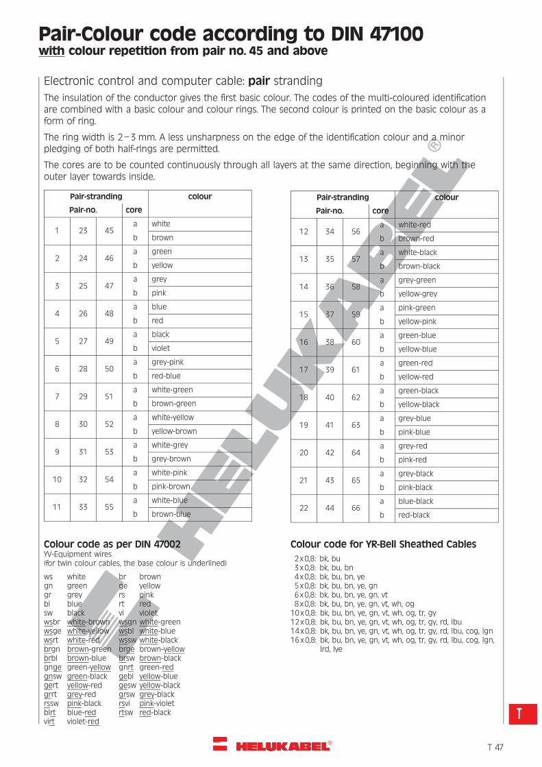
R
Pair-Colour code according to DIN 47100with colour repetition from pair no. 45 and above
Electronic control and computer cable: pair stranding
The insulation of the conductor gives the first basic colour. The codes of the multi-coloured identificationare combined with a basic colour and colour rings. The second colour is printed on the basic colour as aform of ring.
The ring width is 2–3 mm. A less unsharpness on the edge of the identification colour and a minorpledging of both half-rings are permitted.
The cores are to be counted continuously through all layers at the same direction, beginning with theouter layer towards inside.
Pair-stranding colour
Pair-no. core
1 23 45a white
b brown
2 24 46a green
b yellow
3 25 47a grey
b pink
4 26 48a blue
b red
5 27 49a black
b violet
6 28 50a grey-pink
b red-blue
7 29 51a white-green
b brown-green
8 30 52a white-yellow
b yellow-brown
9 31 53a white-grey
b grey-brown
10 32 54a white-pink
b pink-brown
11 33 55a white-blue
b brown-blue
Colour code as per DIN 47002YV-Equipment wires(for twin colour cables, the base colour is underlined)
ws white br browngn green ge yellowgr grey rs pinkbl blue rt redsw black vi violetwsbr white-brown wsgn white-greenwsge white-yellow wsbl white-bluewsrt white-red wssw white-blackbrgn brown-green brge brown-yellowbrbl brown-blue brsw brown-blackgnge green-yellow gnrt green-redgnsw green-black gebl yellow-bluegert yellow-red gesw yellow-blackgrrt grey-red grsw grey-blackrssw pink-black rsvi pink-violetblrt blue-red rtsw red-blackvirt violet-red
Pair-stranding colour
Pair-no. core
12 34 56a white-red
b brown-red
13 35 57a white-black
b brown-black
14 36 58a grey-green
b yellow-grey
15 37 59a pink-green
b yellow-pink
16 38 60a green-blue
b yellow-blue
17 39 61a green-red
b yellow-red
18 40 62a green-black
b yellow-black
19 41 63a grey-blue
b pink-blue
20 42 64a grey-red
b pink-red
21 43 65a grey-black
b pink-black
22 44 66a blue-black
b red-black
Colour code for YR-Bell Sheathed Cables
2x0,8: bk, bu3x0,8: bk, bu, bn4x0,8: bk, bu, bn, ye5x0,8: bk, bu, bn, ye, gn6x0,8: bk, bu, bn, ye, gn, vt8x0,8: bk, bu, bn, ye, gn, vt, wh, og10x0,8: bk, bu, bn, ye, gn, vt, wh, og, tr, gy12x0,8: bk, bu, bn, ye, gn, vt, wh, og, tr, gy, rd, lbu14x0,8: bk, bu, bn, ye, gn, vt, wh, og, tr, gy, rd, lbu, cog, lgn16x0,8: bk, bu, bn, ye, gn, vt, wh, og, tr, gy, rd, lbu, cog, lgn,
lrd, lye
�T 47
T
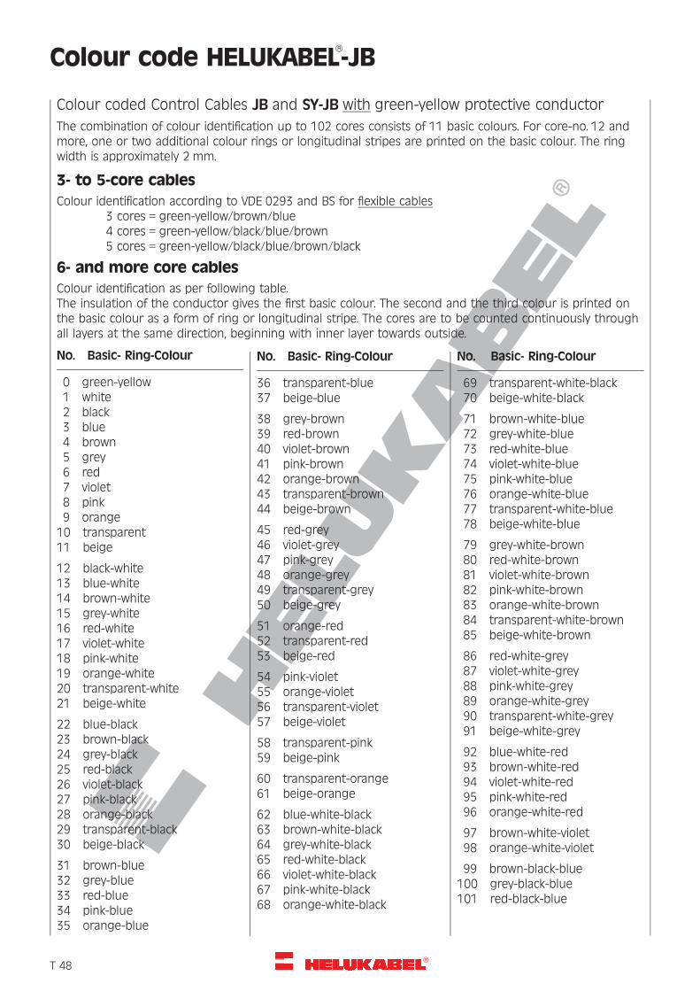
R
Colour code HELUKABEL�-JB
Colour coded Control Cables JB and SY-JB with green-yellow protective conductor
The combination of colour identification up to 102 cores consists of 11 basic colours. For core-no. 12 andmore, one or two additional colour rings or longitudinal stripes are printed on the basic colour. The ringwidth is approximately 2 mm.
3- to 5-core cables
Colour identification according to VDE 0293 and BS for flexible cables3 cores = green-yellow/brown/blue4 cores = green-yellow/black/blue/brown5 cores = green-yellow/black/blue/brown/black
6- and more core cables
Colour identification as per following table.The insulation of the conductor gives the first basic colour. The second and the third colour is printed onthe basic colour as a form of ring or longitudinal stripe. The cores are to be counted continuously throughall layers at the same direction, beginning with inner layer towards outside.
No. Basic- Ring-Colour
0 green-yellow1 white2 black3 blue4 brown5 grey6 red7 violet8 pink9 orange
10 transparent11 beige
12 black-white13 blue-white14 brown-white15 grey-white16 red-white17 violet-white18 pink-white19 orange-white20 transparent-white21 beige-white
22 blue-black23 brown-black24 grey-black25 red-black26 violet-black27 pink-black28 orange-black29 transparent-black30 beige-black
31 brown-blue32 grey-blue33 red-blue34 pink-blue35 orange-blue
No. Basic- Ring-Colour
36 transparent-blue37 beige-blue
38 grey-brown39 red-brown40 violet-brown41 pink-brown42 orange-brown43 transparent-brown44 beige-brown
45 red-grey46 violet-grey47 pink-grey48 orange-grey49 transparent-grey50 beige-grey
51 orange-red52 transparent-red53 beige-red
54 pink-violet55 orange-violet56 transparent-violet57 beige-violet
58 transparent-pink59 beige-pink
60 transparent-orange61 beige-orange
62 blue-white-black63 brown-white-black64 grey-white-black65 red-white-black66 violet-white-black67 pink-white-black68 orange-white-black
No. Basic- Ring-Colour
69 transparent-white-black70 beige-white-black
71 brown-white-blue72 grey-white-blue73 red-white-blue74 violet-white-blue75 pink-white-blue76 orange-white-blue77 transparent-white-blue78 beige-white-blue
79 grey-white-brown80 red-white-brown81 violet-white-brown82 pink-white-brown83 orange-white-brown84 transparent-white-brown85 beige-white-brown
86 red-white-grey87 violet-white-grey88 pink-white-grey89 orange-white-grey90 transparent-white-grey91 beige-white-grey
92 blue-white-red93 brown-white-red94 violet-white-red95 pink-white-red96 orange-white-red
97 brown-white-violet98 orange-white-violet
99 brown-black-blue100 grey-black-blue101 red-black-blue
�T 48
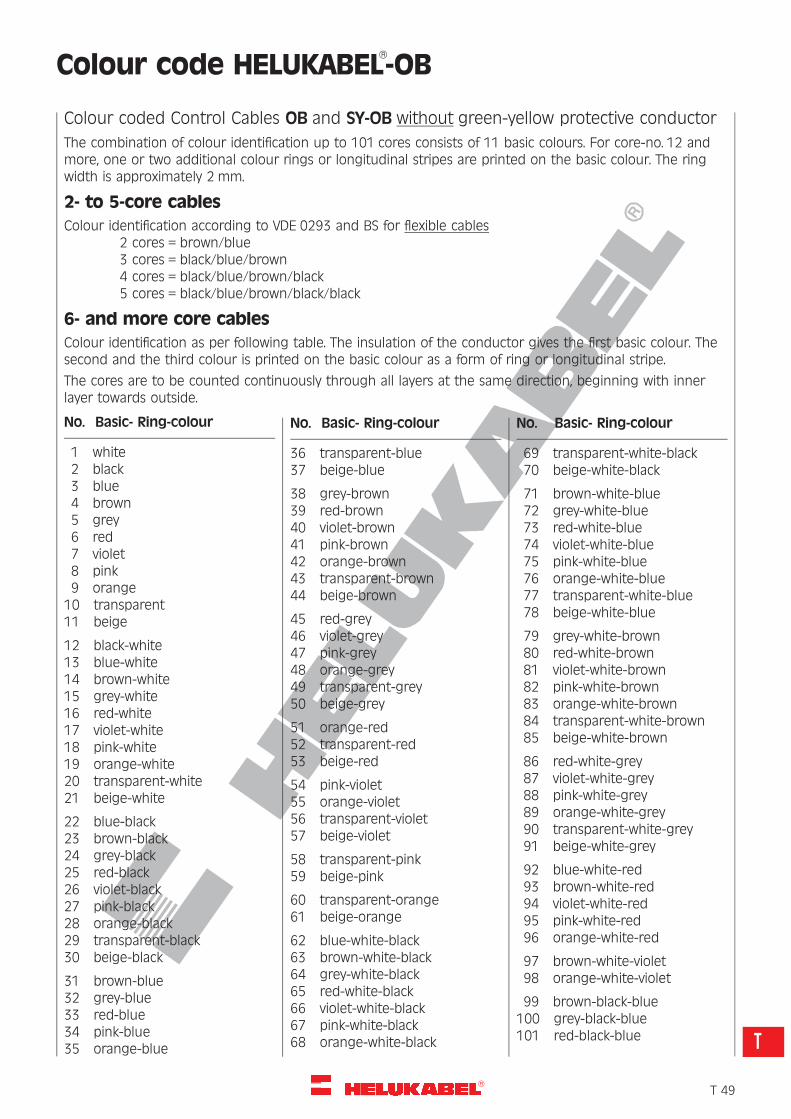
R
Colour code HELUKABEL�-OB
Colour coded Control Cables OB and SY-OB without green-yellow protective conductor
The combination of colour identification up to 101 cores consists of 11 basic colours. For core-no. 12 andmore, one or two additional colour rings or longitudinal stripes are printed on the basic colour. The ringwidth is approximately 2 mm.
2- to 5-core cables
Colour identification according to VDE 0293 and BS for flexible cables2 cores = brown/blue3 cores = black/blue/brown4 cores = black/blue/brown/black5 cores = black/blue/brown/black/black
6- and more core cables
Colour identification as per following table. The insulation of the conductor gives the first basic colour. Thesecond and the third colour is printed on the basic colour as a form of ring or longitudinal stripe.
The cores are to be counted continuously through all layers at the same direction, beginning with innerlayer towards outside.
No. Basic- Ring-colour
1 white2 black3 blue4 brown5 grey6 red7 violet8 pink9 orange
10 transparent11 beige
12 black-white13 blue-white14 brown-white15 grey-white16 red-white17 violet-white18 pink-white19 orange-white20 transparent-white21 beige-white
22 blue-black23 brown-black24 grey-black25 red-black26 violet-black27 pink-black28 orange-black29 transparent-black30 beige-black
31 brown-blue32 grey-blue33 red-blue34 pink-blue35 orange-blue
No. Basic- Ring-colour
36 transparent-blue37 beige-blue
38 grey-brown39 red-brown40 violet-brown41 pink-brown42 orange-brown43 transparent-brown44 beige-brown
45 red-grey46 violet-grey47 pink-grey48 orange-grey49 transparent-grey50 beige-grey
51 orange-red52 transparent-red53 beige-red
54 pink-violet55 orange-violet56 transparent-violet57 beige-violet
58 transparent-pink59 beige-pink
60 transparent-orange61 beige-orange
62 blue-white-black63 brown-white-black64 grey-white-black65 red-white-black66 violet-white-black67 pink-white-black68 orange-white-black
No. Basic- Ring-colour
69 transparent-white-black70 beige-white-black
71 brown-white-blue72 grey-white-blue73 red-white-blue74 violet-white-blue75 pink-white-blue76 orange-white-blue77 transparent-white-blue78 beige-white-blue
79 grey-white-brown80 red-white-brown81 violet-white-brown82 pink-white-brown83 orange-white-brown84 transparent-white-brown85 beige-white-brown
86 red-white-grey87 violet-white-grey88 pink-white-grey89 orange-white-grey90 transparent-white-grey91 beige-white-grey
92 blue-white-red93 brown-white-red94 violet-white-red95 pink-white-red96 orange-white-red
97 brown-white-violet98 orange-white-violet
99 brown-black-blue100 grey-black-blue101 red-black-blue
�T 49
T
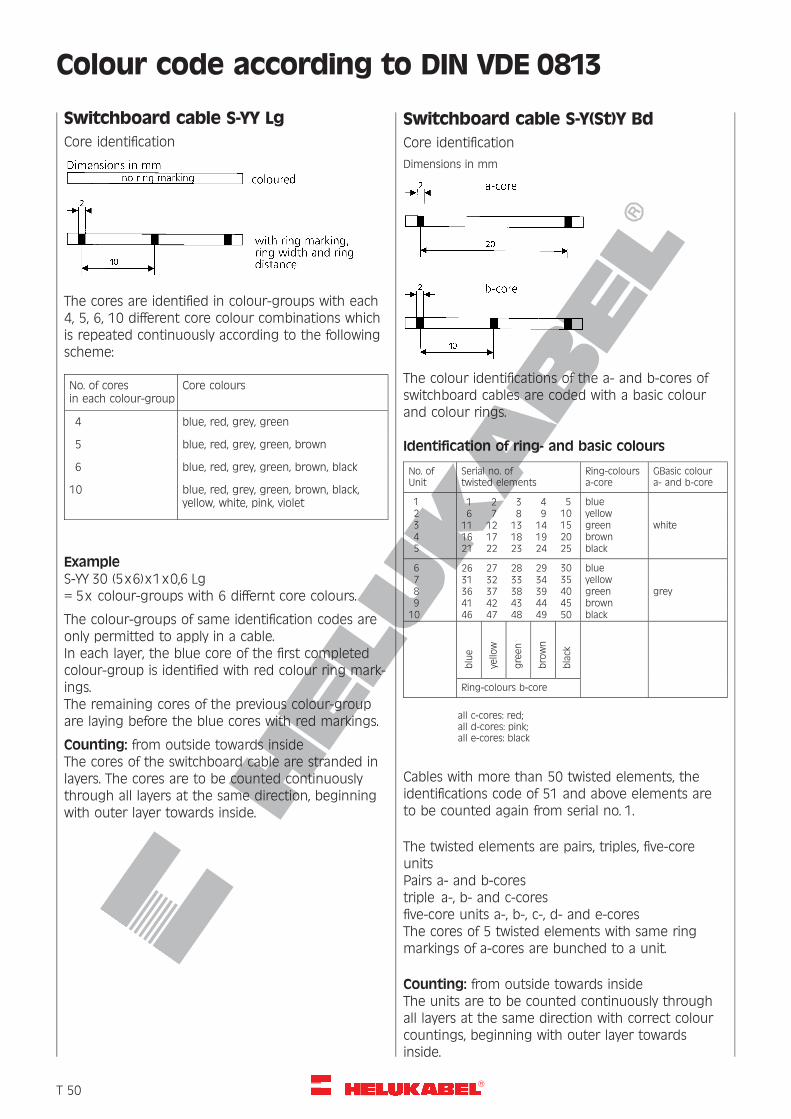
R
Colour code according to DIN VDE 0813
blue
yello
w
green
brown
black
Switchboard cable S-YY Lg
Core identification
The cores are identified in colour-groups with each4, 5, 6, 10 different core colour combinations whichis repeated continuously according to the followingscheme:
No. of coresin each colour-group
Core colours
4 blue, red, grey, green
5 blue, red, grey, green, brown
6 blue, red, grey, green, brown, black
10 blue, red, grey, green, brown, black,yellow, white, pink, violet
ExampleS-YY 30 (5x6)x1x0,6 Lg= 5x colour-groups with 6 differnt core colours.
The colour-groups of same identification codes areonly permitted to apply in a cable.In each layer, the blue core of the first completedcolour-group is identified with red colour ring mark-ings.The remaining cores of the previous colour-groupare laying before the blue cores with red markings.
Counting: from outside towards insideThe cores of the switchboard cable are stranded inlayers. The cores are to be counted continuouslythrough all layers at the same direction, beginningwith outer layer towards inside.
Switchboard cable S-Y(St)Y Bd
Core identification
Dimensions in mm
The colour identifications of the a- and b-cores ofswitchboard cables are coded with a basic colourand colour rings.
Identification of ring- and basic colours
No. ofUnit
Serial no. oftwisted elements
Ring-coloursa-core
GBasic coloura- and b-core
1 1 2 3 4 5 blue2 6 7 8 9 10 yellow3 11 12 13 14 15 green white4 16 17 18 19 20 brown5 21 22 23 24 25 black
6 26 27 28 29 30 blue7 31 32 33 34 35 yellow8 36 37 38 39 40 green grey9 41 42 43 44 45 brown
10 46 47 48 49 50 black
Ring-colours b-core
all c-cores: red;all d-cores: pink;all e-cores: black
Cables with more than 50 twisted elements, theidentifications code of 51 and above elements areto be counted again from serial no. 1.
The twisted elements are pairs, triples, five-coreunitsPairs a- and b-corestriple a-, b- and c-coresfive-core units a-, b-, c-, d- and e-coresThe cores of 5 twisted elements with same ringmarkings of a-cores are bunched to a unit.
Counting: from outside towards insideThe units are to be counted continuously throughall layers at the same direction with correct colourcountings, beginning with outer layer towardsinside.
�T 50
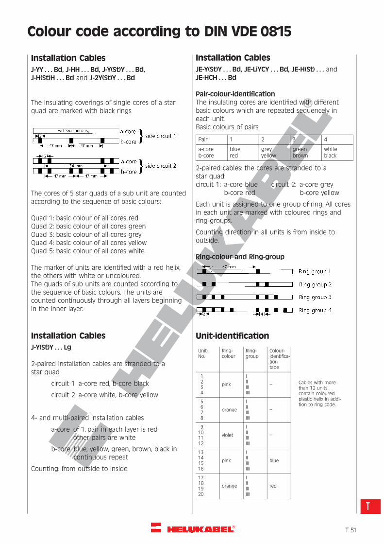
R
Colour code according to DIN VDE 0815
Installation Cables
J-YY . . . Bd, J-HH . . . Bd, J-Y(St)Y . . . Bd,J-H(St)H . . . Bd and J-2Y(St)Y . . . Bd
The insulating coverings of single cores of a starquad are marked with black rings
The cores of 5 star quads of a sub unit are countedaccording to the sequence of basic colours:
Quad 1: basic colour of all cores redQuad 2: basic colour of all cores greenQuad 3: basic colour of all cores greyQuad 4: basic colour of all cores yellowQuad 5: basic colour of all cores white
The marker of units are identified with a red helix,the others with white or uncoloured.The quads of sub units are counted according tothe sequence of basic colours. The units arecounted continuously through all layers beginningin the inner layer.
Installation Cables
J-Y(St)Y . . . Lg
2-paired installation cables are stranded to astar quad
circuit 1 a-core red, b-core black
circuit 2 a-core white, b-core yellow
4- and multi-paired installation cables
a-core of 1. pair in each layer is redother pairs are white
b-core blue, yellow, green, brown, black incontinuous repeat
Counting: from outside to inside.
Installation Cables
JE-Y(St)Y . . . Bd, JE-LiYCY . . . Bd, JE-H(St) . . . andJE-HCH . . . Bd
Pair-colour-identificationThe insulating cores are identified with differentbasic colours which are repeated sequencely ineach unit.Basic colours of pairs
Pair 1 2 3 4
a-coreb-core
bluered
greyyellow
greenbrown
whiteblack
2-paired cables: the cores are stranded to astar quad:circuit 1: a-core blue circuit 2: a-core grey
b-core red b-core yellow
Each unit is assigned to one group of ring. All coresin each unit are marked with coloured rings andring-groups.
Counting direction in all units is from inside tooutside.
Ring-colour and Ring-group
Unit-identification
Unit-No.
Ring-colour
Ring-group
Colour-identifica-tiontape
1234
pink
IIIIIIIIII
–
5678
orange
IIIIIIIIII
–
9101112
violet
IIIIIIIIII
–
13141516
pink
IIIIIIIIII
blue
17181920
orange
IIIIIIIIII
red
Cables with morethan 12 unitscontain colouredplastic helix in addi-tion to ring code.
�T 51
T
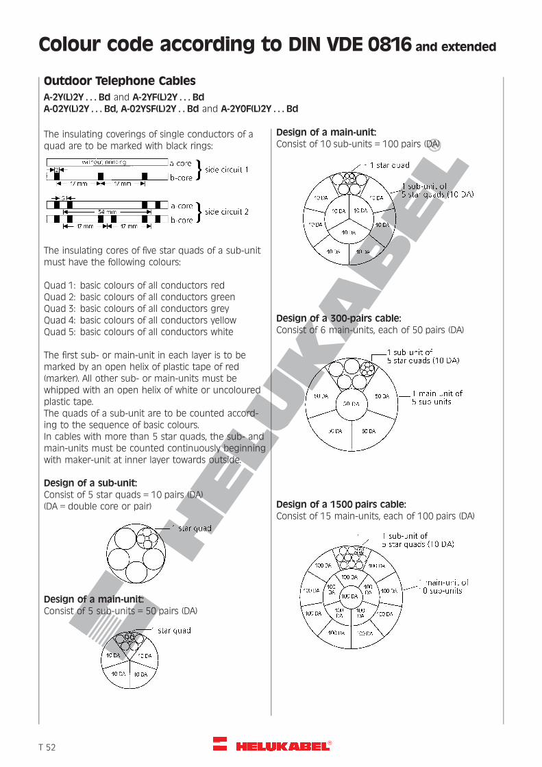
R
Colour code according to DIN VDE 0816 and extended
Outdoor Telephone Cables
A-2Y(L)2Y . . . Bd and A-2YF(L)2Y . . . BdA-02Y(L)2Y . . . Bd, A-02YSF(L)2Y . . Bd and A-2Y0F(L)2Y . . . Bd
The insulating coverings of single conductors of aquad are to be marked with black rings:
The insulating cores of five star quads of a sub-unitmust have the following colours:
Quad 1: basic colours of all conductors redQuad 2: basic colours of all conductors greenQuad 3: basic colours of all conductors greyQuad 4: basic colours of all conductors yellowQuad 5: basic colours of all conductors white
The first sub- or main-unit in each layer is to bemarked by an open helix of plastic tape of red(marker). All other sub- or main-units must bewhipped with an open helix of white or uncolouredplastic tape.The quads of a sub-unit are to be counted accord-ing to the sequence of basic colours.In cables with more than 5 star quads, the sub- andmain-units must be counted continuously beginningwith maker-unit at inner layer towards outside.
Design of a sub-unit:Consist of 5 star quads = 10 pairs (DA)(DA = double core or pair)
Design of a main-unit:Consist of 5 sub-units = 50 pairs (DA)
Design of a main-unit:Consist of 10 sub-units = 100 pairs (DA)
Design of a 300-pairs cable:Consist of 6 main-units, each of 50 pairs (DA)
Design of a 1500 pairs cable:Consist of 15 main-units, each of 100 pairs (DA)
�T 52
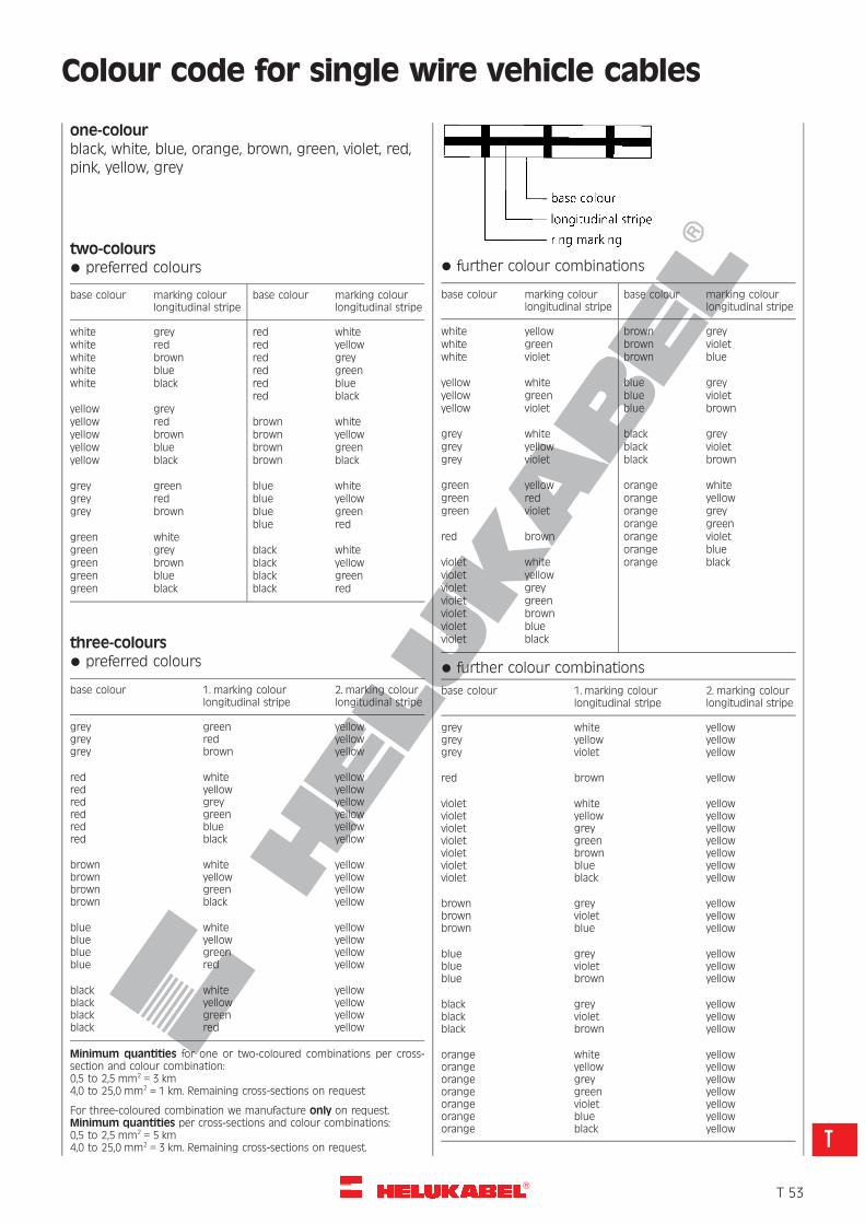
R
Colour code for single wire vehicle cables
one-colourblack, white, blue, orange, brown, green, violet, red,pink, yellow, grey
two-colours* preferred colours
base colour marking colourlongitudinal stripe
base colour marking colourlongitudinal stripe
white grey red whitewhite red red yellowwhite brown red greywhite blue red greenwhite black red blue
red blackyellow greyyellow red brown whiteyellow brown brown yellowyellow blue brown greenyellow black brown black
grey green blue whitegrey red blue yellowgrey brown blue green
blue redgreen whitegreen grey black whitegreen brown black yellowgreen blue black greengreen black black red
three-colours* preferred colours
base colour 1. marking colourlongitudinal stripe
2. marking colourlongitudinal stripe
greygreygrey
greenredbrown
yellowyellowyellow
redredredredredred
whiteyellowgreygreenblueblack
yellowyellowyellowyellowyellowyellow
brownbrownbrownbrown
whiteyellowgreenblack
yellowyellowyellowyellow
blueblueblueblue
whiteyellowgreenred
yellowyellowyellowyellow
blackblackblackblack
whiteyellowgreenred
yellowyellowyellowyellow
Minimum quantities for one or two-coloured combinations per cross-section and colour combination:0,5 to 2,5 mm2 = 3 km4,0 to 25,0 mm2 = 1 km. Remaining cross-sections on request
For three-coloured combination we manufacture only on request.Minimum quantities per cross-sections and colour combinations:0,5 to 2,5 mm2 = 5 km4,0 to 25,0 mm2 = 3 km. Remaining cross-sections on request.
* further colour combinations
base colour marking colourlongitudinal stripe
base colour marking colourlongitudinal stripe
white yellow brown greywhite green brown violetwhite violet brown blue
yellow white blue greyyellow green blue violetyellow violet blue brown
grey white black greygrey yellow black violetgrey violet black brown
green yellow orange whitegreen red orange yellowgreen violet orange grey
orange greenred brown orange violet
orange blueviolet white orange blackviolet yellowviolet greyviolet greenviolet brownviolet blueviolet black
* further colour combinations
base colour 1. marking colourlongitudinal stripe
2. marking colourlongitudinal stripe
greygreygrey
whiteyellowviolet
yellowyellowyellow
red brown yellow
violetvioletvioletvioletvioletvioletviolet
whiteyellowgreygreenbrownblueblack
yellowyellowyellowyellowyellowyellowyellow
brownbrownbrown
greyvioletblue
yellowyellowyellow
blueblueblue
greyvioletbrown
yellowyellowyellow
blackblackblack
greyvioletbrown
yellowyellowyellow
orangeorangeorangeorangeorangeorangeorange
whiteyellowgreygreenvioletblueblack
yellowyellowyellowyellowyellowyellowyellow
�T 53
T
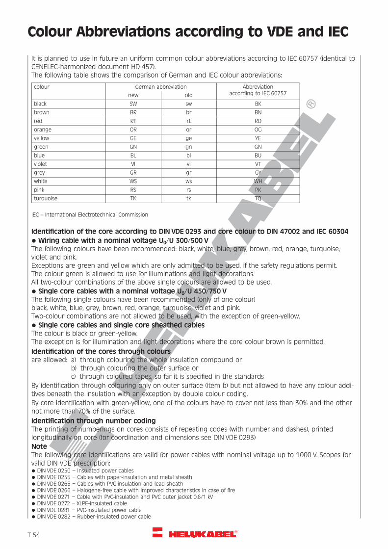
R
Colour Abbreviations according to VDE and IEC
It is planned to use in future an uniform common colour abbreviations according to IEC 60757 (identical toCENELEC-harmonized document HD 457).The following table shows the comparison of German and IEC colour abbreviations:
colour German abbreviation Abbreviationaccording to IEC 60757new old
black SW sw BK
brown BR br BN
red RT rt RD
orange OR or OG
yellow GE ge YE
green GN gn GN
blue BL bl BU
violet VI vi VT
grey GR gr GY
white WS ws WH
pink RS rs PK
turquoise TK tk TQ
IEC = International Electrotechnical Commission
Identification of the core according to DIN VDE 0293 and core colour to DIN 47002 and IEC 60304* Wiring cable with a nominal voltage U0/U 300/500 VThe following colours have been recommended: black, white, blue, grey, brown, red, orange, turquoise,violet and pink.Exceptions are green and yellow which are only admitted to be used, if the safety regulations permit.The colour green is allowed to use for illuminations and light decorations.All two-colour combinations of the above single colours are allowed to be used.* Single core cables with a nominal voltage U0/U 450/750 VThe following single colours have been recommended (only of one colour)black, white, blue, grey, brown, red, orange, turquoise, violet and pink.Two-colour combinations are not allowed to be used, with the exception of green-yellow.* Single core cables and single core sheathed cablesThe colour is black or green-yellow.The exception is for illumination and light decorations where the core colour brown is permitted.
Identification of the cores through coloursare allowed: a) through colouring the whole insulation compound or
b) through colouring the outer surface orc) through coloured tapes, so far it is specified in the standards
By identification through colouring only on outer surface (item b) but not allowed to have any colour addi-tives beneath the insulation with an exception by double colour coding.
By core identification with green-yellow, one of the colours have to cover not less than 30% and the othernot more than 70% of the surface.
Identification through number codingThe printing of numberings on cores consists of repeating codes (with number and dashes), printedlongitudinally on core (for coordination and dimensions see DIN VDE 0293)
NoteThe following core identifications are valid for power cables with nominal voltage up to 1000 V. Scopes forvalid DIN VDE prescription:* DIN VDE 0250 – Insulated power cables* DIN VDE 0255 – Cables with paper-insulation and metal sheath* DIN VDE 0265 – Cables with PVC-insulation and lead sheath* DIN VDE 0266 – Halogene-free cable with improved characteristics in case of fire* DIN VDE 0271 – Cable with PVC-insulation and PVC outer jacket 0,6/1 kV* DIN VDE 0272 – XLPE-insulated cable* DIN VDE 0281 – PVC-insulated power cable* DIN VDE 0282 – Rubber-insulated power cable
�T 54
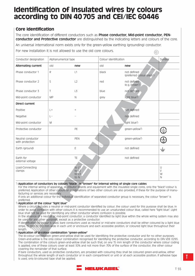
R
Identification of insulated wires by coloursaccording to DIN 40705 and CEI/IEC 60446
Core identification
The core identification of different conductors such as Phase conductor, Mid-point conductor, PEN-conductor and Protective conductor are distinguished by the indicating letters and colours of the core.
An universal international norm exists only for the green-yellow earthing (grounding) conductor.
For new installation it is not allowed to use the old core colours.
Conductor designation Alphanumerical type Colour identification Symbol
Alternating current old new old new
Phase conductor 1 R L1 black not defined(preferred colour black1)
Phase conductor 2 S L2 red not defined(e.g. brown1)
Phase conductor 3 T L3 blue not defined
Mid-point conductor MP N grey light blue2)
Direct current
Positive L+ + not defined
Negative L– – not defined
Mid-point conductor M light blue2)
Protective conductor PE green-yellow3)
Neutral conductorwith protection
PEN green-yellow3)
Earth (ground) E not defined
Earth forexternal voltage
TE not defined
Load-Connectingclamps
to L1to L2to L3to N
UVWN
1) Application of conductors by colours “black“ or “brown“ for internal wiring of single core cablesFor the internal wiring of apparatus, distributor boards and equipment with the insulated single cores, only the “black“-colour ispreferred. Application of other colours or combinations of two other colours are also provided, if these for the purpose of manu-facturing or services are necessary.If only an additional colour for the individual identification of separated conductor group is necessary, the colour “brown“ ispreferred.
2) Application of the colour “light blue“Where a circuit includes a neutral or mid-point conductor identified by colour, the colour used for this purpose shall be blue. Inorder to avoid confusion with other colours it is recommended to use an unsaturated colour blue, called here “light blue“. Lightblue shall not be used for identifying any other conductor where confusion is possible.In the absence of a neutral or mid-point conductor, a conductor identified by light blue within the whole wiring system may alsobe used for any other purposes, except as a protective conductor.If identification by colour is used, bare conductors used as neutral or mid-wire conductors shall be either coloured by a light bluestripe, 15 mm to 100 mm wide in each unit or enclosure and each accessible position, or coloured light blue throughout theirlength.
3) Application of bi-colour combination “green-yellow“The bi-colour combination green-and-yellow shall be used for identifying the protective conductor and for no other purposes.Green-and-yellow is the only colour combination recognised for identifying the protective conductor, according to DIN VDE 0293.The combination of the colours green-and-yellow shall be such that, on any 15 mm length of the conductor where colour codingis applied, one of these colours cover at least 30% and not more than 70% of the surface of the conductor, the other colourcovering the remainder of that surface.If bare conductors, used as protective conductors, are provided with colouring they shall be coloured green-and-yellow, eitherthroughout the whole length of each conductor or in each compartment or unit or at each accessible position. If adhesive tapeis used, only bi-coloured tape shall be applied.
�T 55
T
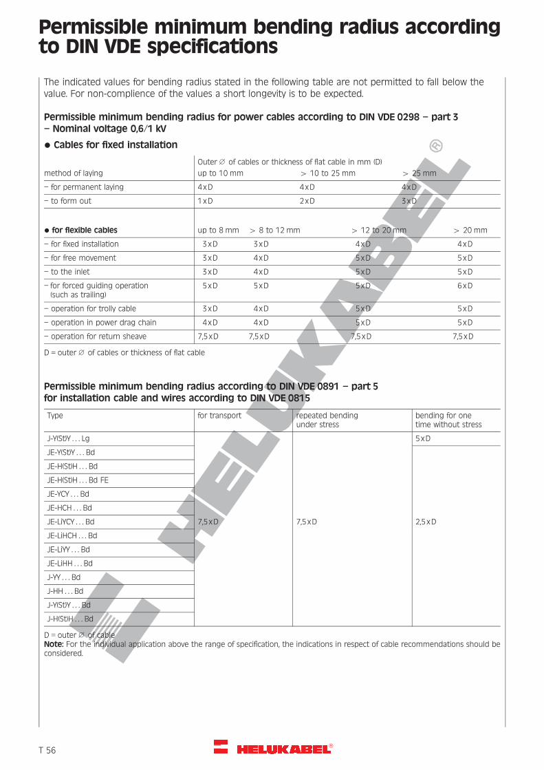
R
Permissible minimum bending radius accordingto DIN VDE specifications
The indicated values for bending radius stated in the following table are not permitted to fall below thevalue. For non-complience of the values a short longevity is to be expected.
Permissible minimum bending radius for power cables according to DIN VDE 0298 – part 3
– Nominal voltage 0,6/1 kV
* Cables for fixed installation
Outer 1 of cables or thickness of flat cable in mm (D)
method of laying up to 10 mm 4 10 to 25 mm 4 25 mm
– for permanent laying 4xD 4xD 4xD
– to form out 1xD 2xD 3xD
* for flexible cables up to 8 mm 4 8 to 12 mm 4 12 to 20 mm 4 20 mm
– for fixed installation 3xD 3xD 4xD 4xD
– for free movement 3xD 4xD 5xD 5xD
– to the inlet 3xD 4xD 5xD 5xD
– for forced guiding operation(such as trailing)
5xD 5xD 5xD 6xD
– operation for trolly cable 3xD 4xD 5xD 5xD
– operation in power drag chain 4xD 4xD 5xD 5xD
– operation for return sheave 7,5xD 7,5xD 7,5 xD 7,5xD
D = outer 1 of cables or thickness of flat cable
Permissible minimum bending radius according to DIN VDE 0891 – part 5for installation cable and wires according to DIN VDE 0815
Type for transport repeated bendingunder stress
bending for onetime without stress
J-Y(St)Y . . . Lg 5xD
JE-Y(St)Y . . . Bd
JE-H(St)H . . . Bd
JE-H(St)H . . . Bd FE
JE-YCY . . . Bd
JE-HCH . . . Bd
JE-LiYCY . . . Bd 7,5xD 7,5xD 2,5xD
JE-LiHCH . . . Bd
JE-LiYY . . . Bd
JE-LiHH . . . Bd
J-YY . . . Bd
J-HH . . . Bd
J-Y(St)Y . . . Bd
J-H(St)H . . . Bd
D = outer 1 of cableNote: For the individual application above the range of specification, the indications in respect of cable recommendations should beconsidered.
�T 56
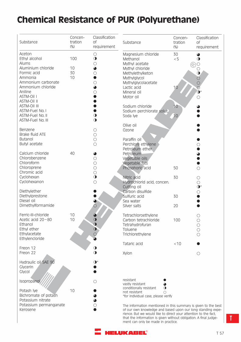
R
Chemical Resistance of PUR (Polyurethane)
SubstanceConcen-tration(%)
Classificationofrequirement
Aceton *Ethyl alcohol 100 gAlums *Aluminium chloride 10Formic acid 30 *Ammonia 10 l
Ammonium carbonate *Ammonium chlorideAniline *ASTM-Oil I l
ASTM-Oil II l
ASTM-Oil III l
ASTM-Fuel No. I l
ASTM-Fuel No. II gASTM-Fuel No. III g
Benzene *Brake fluid ATE *Butanol *Butyl acetate *
Calcium chloride 40Chlorobenzene *Chloroform *Chloroprene *Chromic acid *Cyclohexan gCyclohexanon *
Diethylether l
Diethylprestone l
Diesel oilDimethylformamide *
Ferric-III-chloride 10Acetic acid 20–80 10 gEthanol gEthyl ether gEthylacetate *Ethylencloride
Freon 12 gFreon 22 g
Hydraulic oil SAE 90 g*Glycerin l
Glycol l
Isopropanol *
Potash lye 10 l
Bichromate of potashPotassium nitratePotassium permanganate *Kerosene l
SubstanceConcen-tration(%)
Classificationofrequirement
Magnesium chloride 30Methanol <5 gMythyl acetate *Mythyl chloride *Methylethylketon gMythylglycol *Mythylglycolacetate *Lactic acid 10 *Mineral oil g*Motor oil *
Sodium chloride 10Sodium perchlorate solut. l
Soda lye 10 l
Olive oil l
Ozone l
Paraffin oil l
Perchlore ethylene *Petroleum ether l
PetroleumVegetable oils l
Vegetable fats l
Phosphoric acid 50 *
Nitric acid 30 *Hydrochlorid acid, concen. *Cutting oil g*Carbon disulfide *Sulfuric acid 30 l
Sea water l
Silver salts 20 l
Tetrachloroethylene *Carbon tetrachloride 100 *Tetrahydrofuran *Toluene *Trichlorethylene *
Tataric acid <10 l
Xylon *
resistant l
vastly resistantconditionally resistant gnot resistant **for individual case, please verify
The information mentioned in this summary is given to the bestof our own knowledge and based upon our long standing expe-rience. But we would like to direct your attention to the fact,that the information is given without obligation. A final judge-ment can only be made in practice.
�T 57
T
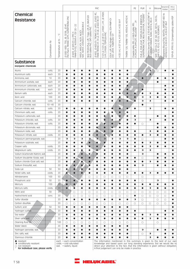
R
Concentration(%)
Temperature
upto
…8C
JZ-500/600/750,JB,O
Z-BL,JZ-HF,
PVC
-Flach
,TRONIC
(LiYY),S
UPERTR
ONIC-PVC
JZ-603,JZ603-CY,Li-TPC-Y,
PAAR-CY-OZ,
N05VV5-F,C
EI20–22
NYSLY,N
YSLYCY,NLSY,NLSCY,
NSY,N
SYCY,H05VV5-F,H
05VVC4V5
-K
MULTIFLEX-Plus,LifY,Trago,Lift-2S,
BAUFLEX
BUS-cables-PVC
,DAT-cables-PVC
JZ-602,JZ-602-CY,TR
ONIC-CY,LiYC
Y,JZ-602RC,
PAAR-TRONIC-CY,SY-JZ,SY-JB,JZ-602RC-CY
F-CY-JZ,Y-CY-JZ,JZ-HF-CY,J-Y(St)Y,J-YY,JE-Y(St)Y,
S-YY,S
-Y(St)Y,TO
PFLEX-PVC
ESU
Y,LifY,P
VC-Single
cores,EDV-PiM
F-CY
ESY,LiFDY,TU
BEFLEX/-CY
H05V-K,H
07V-K,H
03VV-F,H
05VV-F
THERM
120,THERM
105,H
05V2
-K,H
07V2
-K
Coaxial-cable
(PE),L2
-BUS-cable
(PE)
A-2Y(L)2Y,A-2YF(L)2Y,HELU
COM
�...2
Y
PUR-JZ,PUR-JZ-HF,
TOPFLEX-PUR,R
OBOFLEX,
SUPERTR
ONIC-PUR,M
ULTIFLEX-PUR,TOPSE
RV�
J-H(St)H,Secu
rity
Cab
le..E
30/E
90,HELU
COM
�-H
JZ-500-HMH/H
XMHX,
N2XH
,H07Z-K,R
G-H
SiHF,
SiHF/GL-P,S
iF,SiD,S
iFF,
SiF/GL,SiD/G
L,SiHF-C-Si,FZ-LS,
FZ-LSi,N
2GMH2G
Neo
prene-Round/Flat,NSH
TOU,A
IRPORT400Hz
H01N2-D/E,H
05/H
07-,A05/A
07RN-F
FEP-6Y,PTFE-5Y,Compensatingcables-FE
P
PVC PE PUR H SiliconeNeoprene
Rubber
HELU-
FLON�
Chemical
Resistance
SubstanceInorganic chemicals
Alums colts. 20 l l l l l l l l l * g * l l
Aluminium salts each 20 l l l l l l l l l g l
Ammonia, wat. 10 20 l l l l l l l l l l * l l l
Ammonium acetate, wat. each 20 l l l l l l l l l l l
Ammonium carbonate, wat. each 20 l l l l l l l l l * l l
Ammonium chloride, wat. each 20 l l l l l l l l l l l l
Barium salts each 20 l l l l l l l l l l l g l l l
Boric acid 100 20 l l l l l l l l l l g g l l l
Calcium chloride, wat. colts. 20 l l l l l l l l l l g g l l
Calcium chloride, wat. 10–40 20 l
Calcium nitrate, wat. colts. 20 l l l l l l l l l l g l l
Chromium salts, wat. colts. 20 l l l l l l l l l l
Potassium carbonate, wat. 20 l l l l l l l l l l l l l
Potassium chlorate, wat. colts. 20 l l l l l l l l l g g l l
Potassium chloride, wat. colts. 20 l l l l l l l l l l * l l
Potassium dicromate, wat. 20 l l l l l l l l l l l l
Potassium iodie, wat. 20 l l l l l l l l l l g l l l
Potassium nitrate, wat. colds. 20 l l l l l l l l l l l g l l l
Potassium permanganate, wat. 20 g g g g g g g g g l * l l
Potassium sulphate, wat. 20 l l l l l l l l l l l g l l l
Copper salts colds. 20 l l l l l l l l l l l g l l l
Megnesium salts colds. 20 l l l l l l l l l l g g l
Sodium bicarbonate (Natron), wat. 20 l l l l l l l l l g l l l
Sodium bisulphite (Soda), wat. 20 l l l l l l l l l l * l l l
Sodium chloride (Cook salt), wat. 20 l l l l l l l l l l l g l l l
Sodium thiosulfat, wat. 20 l l l l l l l l l l g l l l
Soda Lye 50 50 l l l l l l l l l l
Nickel salts, wat. colds. 20 l l l l l l l l l l l g l l l
Nitrobenzene 100 50 * * * * * * * * * *
Phosphoric acid 50 20 l l l l l l l l l l * g l
Mercury 100 20 l l l l l l l l l l l l l l l
Mercury salts colds. 20 l l l l l l l l l l l g l l l
Nitric acid 30 20 * * * * * * * * * * * * * * l
Hydrochlorid acid conc. 20 * * * * * * * * * l * * * * l
Sulfur dioxide 20 l l l l l l l l l g * * * l
Carbon disulfide 20 * * * * * * * * * * * * * * l
Sulfuric acid 50 50 l l l l l l l l l l
Hydrogen sulfide 20 l l l l l l l l l l l l
Sea water 20 l l l l l l l l l l l g l l l
Silver salts, wat. 20 l l l l l l l l l l l g l l l
Cleaning fluid lye 2 100 * * * * * * * * * * *
Water (dest.) 20 l l l l l l l l l
Hydrogen peroxide, wat. 20 l l l l l l l l l g l l l
Zinc salts, wat. 20 l l l l l l l l l * g l l
Stannous chloride 20 l l l l l l l l l g l l l
l resistantg conditionally resistant* not resistant* for individual case, please verify
each = each concentrationcolds. = cold saturatedwat. = watery, liquid
The information mentioned in this summary is given to the best of our ownknowledge and based upon our long standing experience. But we would like todirect your attention to the fact, that the information is given without obligation.A final judgement can only be made in practice.
�T 58
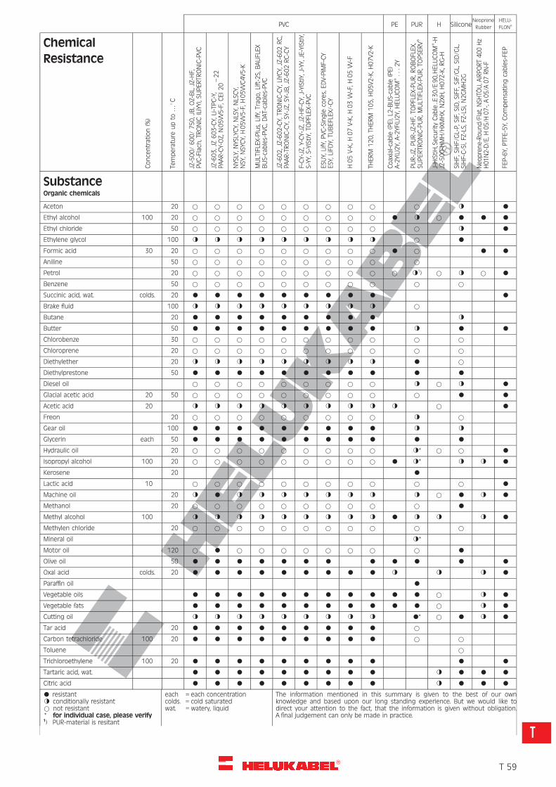
R
Concentration(%)
Temperature
upto
…8C
JZ-500/600/750,JB,O
Z-BL,JZ-HF,
PVC
-Flach
,TRONIC
(LiYY),S
UPERTR
ONIC-PVC
JZ-603,JZ603-CY,Li-TPC-Y,
PAAR-CY-OZ,
N05VV5-F,C
EI20–22
NYSLY,N
YSLYCY,NLSY,NLSCY,
NSY,N
SYCY,H05VV5-F,H
05VVC4V5
-K
MULTIFLEX-Plus,LifY,Trago,Lift-2S,
BAUFLEX
BUS-cables-PVC
,DAT-cables-PVC
JZ-602,JZ-602-CY,TR
ONIC-CY,LiYC
Y,JZ-602RC,
PAAR-TRONIC-CY,SY-JZ,SY-JB,JZ-602RC-CY
F-CY-JZ,Y-CY-JZ,JZ-HF-CY,J-Y(St)Y,J-YY,JE-Y(St)Y,
S-YY,S
-Y(St)Y,TO
PFLEX-PVC
ESU
Y,LifY,P
VC-Single
cores,EDV-PiM
F-CY
ESY,LiFDY,TU
BEFLEX/-CY
H05V-K,H
07V-K,H
03VV-F,H
05VV-F
THERM
120,THERM
105,H
05V2
-K,H
07V2
-K
Coaxial-cable
(PE),L2
-BUS-cable
(PE)
A-2Y(L)2Y,A-2YF(L)2Y,HELU
COM
�...2
Y
PUR-JZ,PUR-JZ-HF,
TOPFLEX-PUR,R
OBOFLEX,
SUPERTR
ONIC-PUR,M
ULTIFLEX-PUR,TOPSE
RV�
J-H(St)H,Secu
rity
Cab
le..E
30/E
90,HELU
COM
�-H
JZ-500-HMH/H
XMHX,
N2XH
,H07Z-K,R
G-H
SiHF,
SiHF/GL-P,S
iF,SiD,S
iFF,
SiF/GL,SiD/G
L,SiHF-C-Si,FZ-LS,
FZ-LSi,N
2GMH2G
Neo
prene-Round/Flat,NSH
TOU,A
IRPORT400Hz
H01N2-D/E,H
05/H
07-,A05/A
07RN-F
FEP-6Y,PTFE-5Y,Compensatingcables-FE
P
PVC PE PUR H SiliconeNeoprene
Rubber
HELU-
FLON�
Chemical
Resistance
SubstanceOrganic chemicals
Aceton 20 * * * * * * * * * * g l
Ethyl alcohol 100 20 * * * * * * * * * l g * l l l
Ethyl chloride 50 * * * * * * * * * * g l
Ethylene glycol 100 g g g g g g g g g * l
Formic acid 30 20 * * * * * * * * * l * l l
Aniline 50 * * * * * * * * * *
Petrol 20 * * * * * * * * * * g1) * g * l
Benzene 50 * * * * * * * * * * *
Succinic acid, wat. colds. 20 l l l l l l l l l l
Brake fluid 100 g g g g g g g g g *
Butane 20 l l l l l l l l l g
Butter 50 l l l l l l l l l g l l
Chlorobenze 30 * * * * * * * * * * *
Chloroprene 20 * * * * * * * * * * *
Diethylether 20 g g g g g g g g g l *
Diethylprestone 50 l l l l l l l l l l l
Diesel oil * * * * * * * * * g * g l
Glacial acetic acid 20 50 * * * * * * * * * * l l
Acetic acid 20 g g g g g g g g g g * l
Freon 20 * * * * * * * * * g *
Gear oil 100 l l l l l l l l l g g
Glycerin each 50 l l l l l l l l l l l
Hydraulic oil 20 * * * * * * * * * g* * * l
Isopropyl alcohol 100 20 * * * * * * * * * l g* g g l
Kerosene 20 l
Lactic acid 10 * * * * * * * * * * * l
Machine oil 20 g l g g g g g g g g * l g l
Methanol 20 * * * * * * * * * * l
Methyl alcohol 100 g g g g g g g g g l g g g l
Methylen chloride 20 * * * * * * * * * * *
Mineral oil g*
Motor oil 120 * l * * * * * * * * l
Olive oil 50 l l l l l l l l l l l l
Oxal acid colds. 20 l l l l l l l l l g g g l
Paraffin oil l
Vegetable oils l l l l l l l l l l l * g l
Vegetable fats l l l l l l l l l l l * g l
Cutting oil g g g g g g g g g l* * l g l
Tar acid 20 l l l l l l l l l *
Carbon tetrachloride 100 20 l l l l l l l l l * *
Toluene *
Trichloroethylene 100 20 l l l l l l l l l l l
Tartaric acid, wat. l l l l l l l l l g l l l
Citric acid l l l l l l l l l g l l l
l resistantg conditionally resistant* not resistant* for individual case, please verify1) PUR-material is resitant
each = each concentrationcolds. = cold saturatedwat. = watery, liquid
The information mentioned in this summary is given to the best of our ownknowledge and based upon our long standing experience. But we would like todirect your attention to the fact, that the information is given without obligation.A final judgement can only be made in practice.
�T 59
T
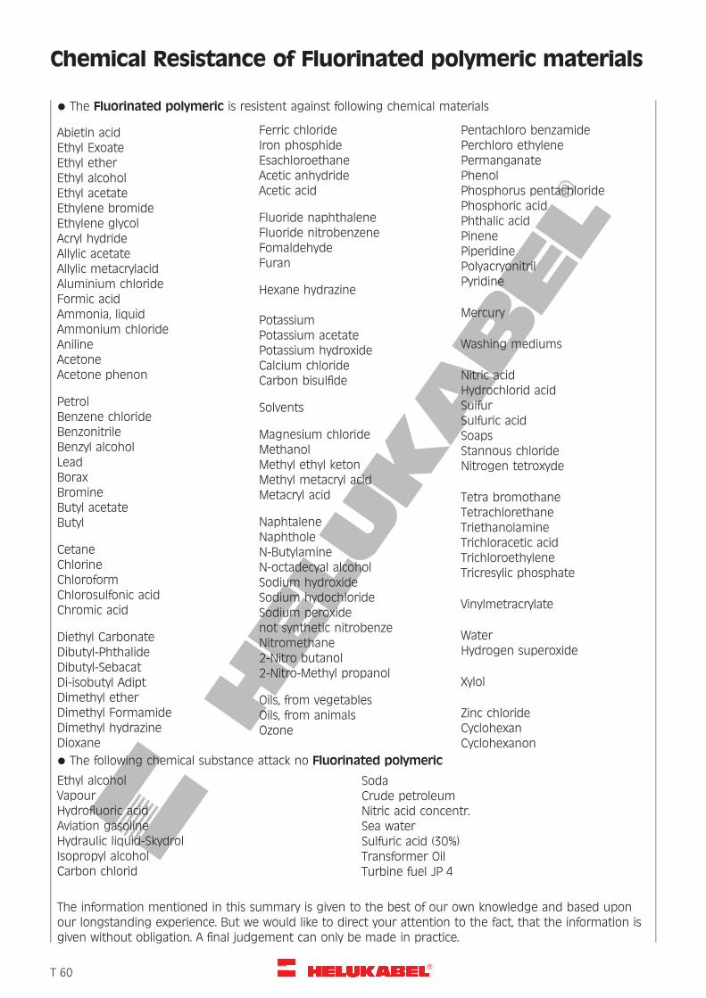
R
Chemical Resistance of Fluorinated polymeric materials
* The Fluorinated polymeric is resistent against following chemical materials
Abietin acidEthyl ExoateEthyl etherEthyl alcoholEthyl acetateEthylene bromideEthylene glycolAcryl hydrideAllylic acetateAllylic metacrylacidAluminium chlorideFormic acidAmmonia, liquidAmmonium chlorideAnilineAcetoneAcetone phenon
PetrolBenzene chlorideBenzonitrileBenzyl alcoholLeadBoraxBromineButyl acetateButyl
CetaneChlorineChloroformChlorosulfonic acidChromic acid
Diethyl CarbonateDibutyl-PhthalideDibutyl-SebacatDi-isobutyl AdiptDimethyl etherDimethyl FormamideDimethyl hydrazineDioxane
Ferric chlorideIron phosphideEsachloroethaneAcetic anhydrideAcetic acid
Fluoride naphthaleneFluoride nitrobenzeneFomaldehydeFuran
Hexane hydrazine
PotassiumPotassium acetatePotassium hydroxideCalcium chlorideCarbon bisulfide
Solvents
Magnesium chlorideMethanolMethyl ethyl ketonMethyl metacryl acidMetacryl acid
NaphtaleneNaphtholeN-ButylamineN-octadecyal alcoholSodium hydroxideSodium hydochlorideSodium peroxidenot synthetic nitrobenzeNitromethane2-Nitro butanol2-Nitro-Methyl propanol
Oils, from vegetablesOils, from animalsOzone
Pentachloro benzamidePerchloro ethylenePermanganatePhenolPhosphorus pentachloridePhosphoric acidPhthalic acidPinenePiperidinePolyacryonitrilPyridine
Mercury
Washing mediums
Nitric acidHydrochlorid acidSulfurSulfuric acidSoapsStannous chlorideNitrogen tetroxyde
Tetra bromothaneTetrachlorethaneTriethanolamineTrichloracetic acidTrichloroethyleneTricresylic phosphate
Vinylmetracrylate
WaterHydrogen superoxide
Xylol
Zinc chlorideCyclohexanCyclohexanon
* The following chemical substance attack no Fluorinated polymeric
Ethyl alcoholVapourHydrofluoric acidAviation gasolineHydraulic liquid-SkydrolIsopropyl alcoholCarbon chlorid
SodaCrude petroleumNitric acid concentr.Sea waterSulfuric acid (30%)Transformer OilTurbine fuel JP 4
The information mentioned in this summary is given to the best of our own knowledge and based uponour longstanding experience. But we would like to direct your attention to the fact, that the information isgiven without obligation. A final judgement can only be made in practice.
�T 60
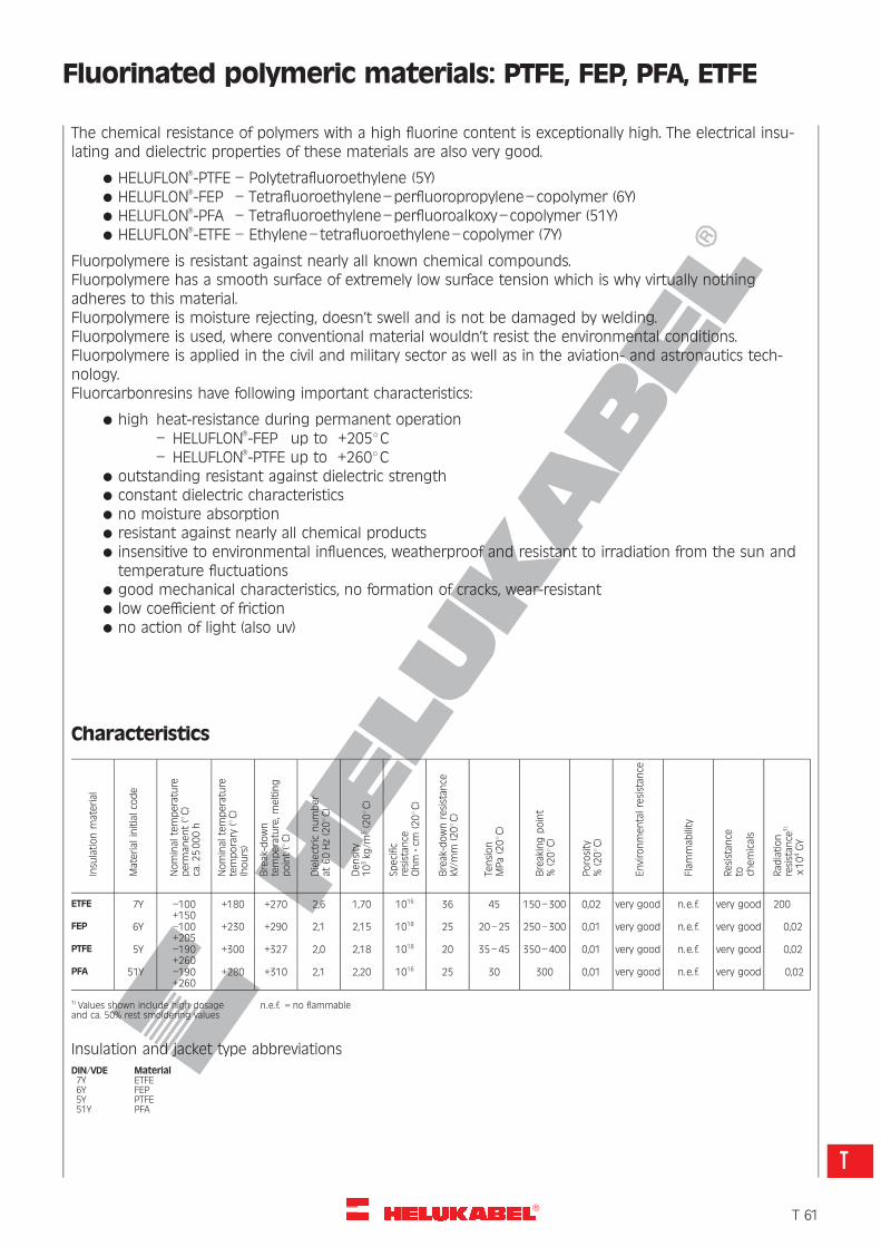
R
Fluorinated polymeric materials: PTFE, FEP, PFA, ETFE
The chemical resistance of polymers with a high fluorine content is exceptionally high. The electrical insu-lating and dielectric properties of these materials are also very good.
* HELUFLON�-PTFE – Polytetrafluoroethylene (5Y)* HELUFLON�-FEP – Tetrafluoroethylene–perfluoropropylene–copolymer (6Y)* HELUFLON�-PFA – Tetrafluoroethylene–perfluoroalkoxy–copolymer (51Y)* HELUFLON�-ETFE – Ethylene–tetrafluoroethylene–copolymer (7Y)
Fluorpolymere is resistant against nearly all known chemical compounds.Fluorpolymere has a smooth surface of extremely low surface tension which is why virtually nothingadheres to this material.Fluorpolymere is moisture rejecting, doesn’t swell and is not be damaged by welding.Fluorpolymere is used, where conventional material wouldn’t resist the environmental conditions.Fluorpolymere is applied in the civil and military sector as well as in the aviation- and astronautics tech-nology.Fluorcarbonresins have following important characteristics:
* high heat-resistance during permanent operation
– HELUFLON�-FEP up to +2058C– HELUFLON�-PTFE up to +2608C
* outstanding resistant against dielectric strength* constant dielectric characteristics* no moisture absorption* resistant against nearly all chemical products* insensitive to environmental influences, weatherproof and resistant to irradiation from the sun and
temperature fluctuations* good mechanical characteristics, no formation of cracks, wear-resistant* low coefficient of friction* no action of light (also uv)
Insu
lationmaterial
Material
initialco
de
Nominal
temperature
perm
anent(8C)
ca.2
5000h
Nominal
temperature
temporary
(8C)
(hours)
Break-down
temperature,m
elting
point(8C)
Dielectricnumber
at60Hz(208C
)
Density
103kg
/m3(208C
)
Specific
resistan
ceOhm
?cm
(208C
)
Break-downresistan
cekV/m
m(208C
)
Tension
MPa(208C
)
Breakingpoint
%(208C
)
Porosity
%(208C
)
Environmentalresistan
ce
Flam
mab
ility
Resistan
ceto ch
emicals
Rad
iation
resistan
ce1)
x104GY
Characteristics
ETFE 7Y –100+150
+180 +270 2,6 1,70 1016 36 45 150–300 0,02 very good n.e. f. very good 200
FEP 6Y –100+205
+230 +290 2,1 2,15 1018 25 20–25 250–300 0,01 very good n.e. f. very good 0,02
PTFE 5Y –190+260
+300 +327 2,0 2,18 1018 20 35–45 350–400 0,01 very good n.e. f. very good 0,02
PFA 51Y –190+260
+280 +310 2,1 2,20 1016 25 30 300 0,01 very good n.e. f. very good 0,02
1) Values shown include high dosage n.e. f. = no flammableand ca. 50% rest smoldering values
Insulation and jacket type abbreviationsDIN/VDE Material7Y ETFE6Y FEP5Y PTFE51Y PFA
�T 61
T
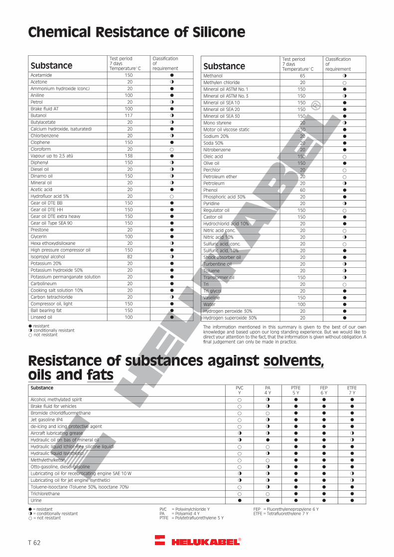
R
Chemical Resistance of Silicone
SubstanceTest period7 daysTemperature8C
Classificationofrequirement
Acetamide 150 l
Acetone 20 g
Ammonium hydroxide (conc.) 20 l
Aniline 100 l
Petrol 20 g
Brake fluid AT 100 l
Butanol 117 g
Butylacetate 20 g
Calcium hydroxide, (saturated) 20 l
Chlorbenzene 20 g
Clophene 150 l
Cloroform 20 *
Vapour up to 2,5 atu 138 l
Diphenyl 150 g
Diesel oil 20 g
Dinamo oil 150 g
Mineral oil 20 g
Acetic acid 20 l
Hydrofluor acid 5% 20 *
Gear oil DTE BB 150 l
Gear oil DTE HH 150 l
Gear oil DTE extra heavy 150 l
Gear oil Type SEA 90 150 l
Prestone 20 l
Glycerin 100 l
Hexa ethoxydisiloxane 20 g
High pressure compressor oil 150 l
Isopropyl alcohol 82 g
Potassium 20% 20 l
Potassium hydroxide 50% 20 l
Potassium permanganate solution 20 l
Carbolineum 20 l
Cooking salt solution 10% 20 l
Carbon tetrachloride 20 g
Compressor oil, light 150 l
Ball bearing fat 150 l
Linseed oil 100 l
l resistantg conditionally resistant* not resistant
SubstanceTest period7 daysTemperature8C
Classificationofrequirement
Methanol 65 g
Methylen chloride 20 *
Mineral oil ASTM No. 1 150 l
Mineral oil ASTM No. 3 150 g
Mineral oil SEA 10 150 l
Mineral oil SEA 20 150 l
Mineral oil SEA 30 150 l
Mono styrene 20 g
Motor oil viscose static 150 l
Sodium 20% 20 l
Soda 50% 20 l
Nitrobenzene 20 l
Oleic acid 150 *
Olive oil 150 l
Perchlor 20 *
Petroleum ether 20 *
Petroleum 20 g
Phenol 60 l
Phosphoric acid 30% 20 l
Pyridine 20 g
Regulator oil 150 *
Castor oil 150 l
Hydrochlorid acid 10% 20 l
Nitric acid conc. 20 *
Nitric acid 10% 20 g
Sulfuric acid, conc. 20 *
Sulfuric acid, 10% 20 l
Shock absorber oil 20 l
Turbentine oil 20 g
Toluene 20 g
Transformer oil 150 g
Tri 20 *
Tri glycol 20 l
Vaseline 150 l
Water 100 l
Hydrogen peroxide 30% 20 l
Hydrogen superoxide 30% 20 l
The information mentioned in this summary is given to the best of our ownknowledge and based upon our long standing experience. But we would like todirect your attention to the fact, that the information is given without obligation. Afinal judgement can only be made in practice.
Resistance of substances against solvents,oils and fatsSubstance PVC
YPA4 Y
PTFE5 Y
FEP6 Y
ETFE7 Y
Alcohol, methylated spirit * g l l l
Brake fluid for vehicles * g l l l
Bromide chloridfluormethane * * l l l
Jet gasoline IP4 * g l l l
de-icing and icing protective agent * g l l l
Aircraft lubricating grease g g l l g
Hydraulic oil on bas of mineral oil g l l l g
Hydraulic liquid (chlor-free silicone liquid) * * l l l
Hydraulic liquid (synthetic) * g l l l
Methylethylketon * * l l l
Otto-gasoline, diesel gasoline * g l l l
Lubricating oil for recebrocating engine SAE 10 W g g l l g
Lubricating oil for jet engine (synthetic) g g l l g
Toluene-Isooctane (Toluene 30%, Isooctane 70%) * g l l l
Trichlorethane * * l l l
Urine l l l l l
l = resistant PVC = Polyvinylchloride Y FEP = Fluorethylenepropylene 6 Yg = conditionally resistant PA = Polyamid 4 Y ETFE = Tetrafluorethylene 7 Y* = not resistant PTFE = Polytetrafluorethylene 5 Y
�T 62
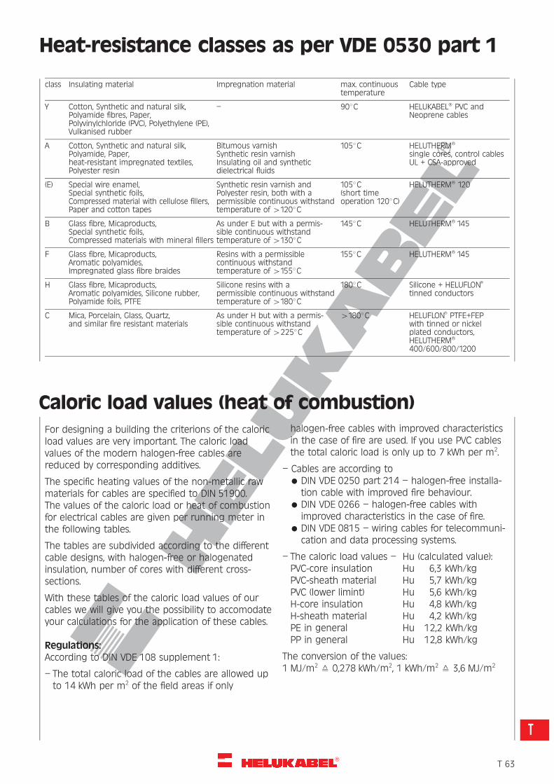
R
Heat-resistance classes as per VDE 0530 part 1
class Insulating material Impregnation material max. continuoustemperature
Cable type
Y Cotton, Synthetic and natural silk,Polyamide fibres, Paper,Polyvinylchloride (PVC), Polyethylene (PE),Vulkanised rubber
– 908C HELUKABEL� PVC andNeoprene cables
A Cotton, Synthetic and natural silk,Polyamide, Paper,heat-resistant impregnated textiles,Polyester resin
Bitumous varnishSynthetic resin varnishInsulating oil and syntheticdielectrical fluids
1058C HELUTHERM�
single cores, control cablesUL + CSA-approved
(E) Special wire enamel,Special synthetic foils,Compressed material with cellulose fillers,Paper and cotton tapes
Synthetic resin varnish andPolyester resin, both with apermissible continuous withstandtemperature of 41208C
1058C(short timeoperation 1208C)
HELUTHERM� 120
B Glass fibre, Micaproducts,Special synthetic foils,Compressed materials with mineral fillers
As under E but with a permis-sible continuous withstandtemperature of 41308C
1458C HELUTHERM� 145
F Glass fibre, Micaproducts,Aromatic polyamides,Impregnated glass fibre braides
Resins with a permissiblecontinuous withstandtemperature of 41558C
1558C HELUTHERM� 145
H Glass fibre, Micaproducts,Aromatic polyamides, Silicone rubber,Polyamide foils, PTFE
Silicone resins with apermissible continuous withstandtemperature of 41808C
1808C Silicone + HELUFLON�
tinned conductors
C Mica, Porcelain, Glass, Quartz,and similar fire resistant materials
As under H but with a permis-sible continuous withstandtemperature of 42258C
41808C HELUFLON� PTFE+FEPwith tinned or nickelplated conductors,HELUTHERM�
400/600/800/1200
Caloric load values (heat of combustion)For designing a building the criterions of the caloricload values are very important. The caloric loadvalues of the modern halogen-free cables arereduced by corresponding additives.
The specific heating values of the non-metallic rawmaterials for cables are specified to DIN 51900.The values of the caloric load or heat of combustionfor electrical cables are given per running meter inthe following tables.
The tables are subdivided according to the differentcable designs, with halogen-free or halogenatedinsulation, number of cores with different cross-sections.
With these tables of the caloric load values of ourcables we will give you the possibility to accomodateyour calculations for the application of these cables.
Regulations:According to DIN VDE 108 supplement 1:
– The total caloric load of the cables are allowed upto 14 kWh per m2 of the field areas if only
halogen-free cables with improved characteristicsin the case of fire are used. If you use PVC cablesthe total caloric load is only up to 7 kWh per m2.
– Cables are according to* DIN VDE 0250 part 214 – halogen-free installa-
tion cable with improved fire behaviour.* DIN VDE 0266 – halogen-free cables with
improved characteristics in the case of fire.* DIN VDE 0815 – wiring cables for telecommuni-
cation and data processing systems.
– The caloric load values – Hu (calculated value):PVC-core insulation Hu 6,3 kWh/kgPVC-sheath material Hu 5,7 kWh/kgPVC (lower limint) Hu 5,6 kWh/kgH-core insulation Hu 4,8 kWh/kgH-sheath material Hu 4,2 kWh/kgPE in general Hu 12,2 kWh/kgPP in general Hu 12,8 kWh/kg
The conversion of the values:1 MJ/m2 = 0,278 kWh/m2, 1 kWh/m2 = 3,6 MJ/m2
�T 63
T
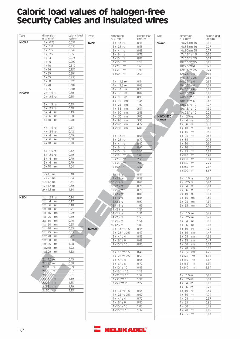
R
Caloric load values of halogen-freeSecurity Cables and insulated wires
Type dimensionn x mm2
caloric loadkWh/m
NHXAF 1 x 0.75 0,031
1 x 1,0 0,033
1 x 1,5 0,049
1 x 2,5 0,059
1 x 4 0,074
1 x 6 0,090
1 x 10 0,112
1 x 16 0,137
1 x 25 0,204
1 x 35 0,235
1 x 50 0,323
1 x 70 0,381
1 x 95 0,504
NHXMH 2 x 1,5 re 0,30
2 x 2,5 re 0,35
3 x 1,5 re 0,33
3 x 2,5 re 0,38
3 x 4 re 0,49
3 x 6 re 0,60
3 x 10 re 0,78
4 x 1,5 re 0,37
4 x 2,5 re 0,42
4 x 4 re 0,49
4 x 6 re 0,68
4 x 10 re 0,90
5 x 1,5 re 0,42
5 x 2,5 re 0,49
5 x 4 re 0,70
5 x 6 re 0,79
5 x 10 re 1,04
7 x 1,5 re 0,48
7 x 2,5 re 0,64
10 x 1,5 re 0,61
12 x 1,5 re 0,69
24 x 1,5 re 1,14
N2XH 1 x 2,5 re 0,14
1 x 4 re 0,17
1 x 6 re 0,18
1 x 10 re 0,21
1 x 16 rm 0,29
1 x 25 rm 0,39
2 x 35 rm 0,46
1 x 50 rm 0,53
1 x 70 rm 0,55
1 x 95 rm 0,63
1 x 120 rm 0,72
1 x 150 rm 0,90
1 x 185 rm 1,08
1 x 240 rm 1,22
1 x 300 rm 1,32
2 x 1,5 re 0,45
2 x 2,5 re 0,50
2 x 4 re 0,59
2 x 6 re 0,67
2 x 10 re 0,81
2 x 16 rm 1,19
2 x 25 rm 1,53
2 x 35 rm 1,79
2 x 50 rm 2,13
Type dimensionn x mm2
caloric loadkWh/m
N2XH 3 x 1,5 re 0,48
3 x 2,5 re 0,56
3 x 4 re 0,65
3 x 6 re 0,73
3 x 10 re 0,86
3 x 16 rm 1,19
3 x 25 rm 1,65
3 x 35 rm 1,95
3 x 50 rm 2,31
4 x 1,5 re 0,54
4 x 2,5 re 0,63
4 x 4 re 0,73
4 x 6 re 0,82
4 x 10 re 0,99
4 x 16 rm 1,43
4 x 25 rm 1,97
4 x 35 rm 2,31
4 x 50 rm 2,89
4 x 70 rm 3,00
4 x 95 rm 3,90
4 x 120 rm 4,77
4 x 150 rm 6,81
5 x 1,5 re 0,62
5 x 2,5 re 0,70
5 x 4 re 0,82
5 x 6 re 0,91
5 x 10 re 1,11
5 x 16 rm 1,68
5 x 25 rm 2,35
5 x 35 rm 2,81
5 x 50 rm 3,42
7 x 1,5 re 0,51
7 x 2,5 re 0,58
10 x 1,5 re 0,68
10 x 2,5 re 0,78
12 x 1,5 re 0,76
12 x 2,5 re 0,88
14 x 1,5 re 0,84
14 x 2,5 re 0,97
19 x 1,5 re 1,05
19 x 2,5 re 1,21
24 x 1,5 re 1,31
24 x 2,5 re 1,53
30 x 1,5 re 1,54
30 x 2,5 re 1,80
N2XCH 2 x 1,5/re 1,5 0,44
2 x 2,5/re 2,5 0,49
2 x 4/re 4 0,59
2 x 6/re 6 0,66
2 x 10/re 10 0,80
3 x 1,5/re 1,5 0,48
3 x 2,5/re 2,5 0,55
3 x 4/re 4 0,64
3 x 6/re 6 0,72
3 x 10/re 10 0,85
3 x 16/rm 16 1,18
3 x 25/rm 16 1,59
3 x 35/rm 16 1,91
3 x 50/rm 25 2,27
4 x 1,5/re 1,5 0,54
4 x 2,5/re 2,5 0,62
4 x 4/re 4 0,72
4 x 6/re 6 0,82
4 x 10/re 10 1,00
4 x 16/rm 16 1,37
Type dimensionn x mm2
caloric loadkWh/m
N2XCH 4 x 25/rm 16 1,94
4 x 35/rm 16 2,27
4 x 50/rm 25 2,77
7 x 1,5/re 1,5 0,50
7 x 2,5/re 2,5 0,57
10 x 1,5/re 2,5 0,66
10 x 2,5/re 4 0,77
12 x 1,5/re 2,5 0,74
12 x 2,5/re 4 0,86
14 x 1,5/re 2,5 0,81
14 x 2,5/re 4 0,95
19 x 1,5/re 4 1,02
19 x 2,5/re 6 1,19
24 x 1,5/re 6 1,25
24 x 2,5/re 10 1,47
30 x 1,5/re 6 1,47
30 x 2,5/re 10 1,77
40 x 1,5/re 10 1,90
40 x 2,5/re 10 2,23
(N)HXH-E30orange
1 x 2,5 re 0,22
1 x 4 re 0,35
1 x 6 re 0,38
1 x 10 re 0,43
1 x 16 rm 0,50
1 x 25 rm 0,68
1 x 35 rm 0,76
1 x 50 rm 0,90
1 x 70 rm 1,09
1 x 95 rm 1,29
1 x 120 rm 1,49
1 x 150 rm 1,84
1 x 185 rm 2,24
1 x 240 rm 2,67
1 x 300 rm 3,67
2 x 1,5 re 0,68
2 x 2,5 re 0,74
2 x 4 re 0,84
2 x 6 re 0,95
2 x 10 re 1,13
2 x 16 rm 1,34
2 x 25 rm 1,94
2 x 35 rm 2,16
3 x 1,5 re 0,72
3 x 2,5 re 0,79
3 x 4 re 0,90
3 x 6 re 1,03
3 x 10 re 1,23
3 x 16 rm 1,47
3 x 25 rm 1,92
3 x 35 rm 2,47
3 x 50 rm 3,03
3 x 70 rm 3,90
3 x 95 rm 4,76
3 x 120 rm 4,63
3 x 150 rm 5,67
3 x 185 rm 6,94
3 x 240 rm 8,84
4 x 1,5 re 0,85
4 x 2,5 re 0,94
4 x 4 re 1,07
4 x 6 re 1,22
4 x 10 re 1,46
4 x 16 rm 1,74
4 x 25 rm 2,57
4 x 35 rm 2,96
4 x 50 rm 3,72
4 x 70 rm 4,85
4 x 95 rm 5,83
�T 64
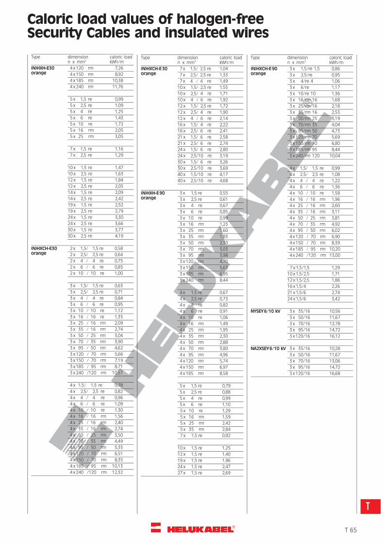
R
Caloric load values of halogen-freeSecurity Cables and insulated wires
Type dimensionn x mm2
caloric loadkWh/m
(N)HXH-E30orange
4 x 120 rm 7,26
4 x 150 rm 8,92
4 x 185 rm 10,38
4 x 240 rm 11,76
5 x 1,5 re 0,99
5 x 2,5 re 1,09
5 x 4 re 1,25
5 x 6 re 1,43
5 x 10 re 1,72
5 x 16 rm 2,05
5 x 25 rm 3,05
7 x 1,5 re 1,16
7 x 2,5 re 1,29
10 x 1,5 re 1,47
10 x 2,5 re 1,63
12 x 1,5 re 1,84
12 x 2,5 re 2,05
14 x 1,5 re 2,09
14 x 2,5 re 2,42
19 x 1,5 re 2,52
19 x 2,5 re 2,79
24 x 1,5 re 3,30
24 x 2,5 re 3,66
30 x 1,5 re 3,77
30 x 2,5 re 4,19
(N)HXCH-E30orange
2 x 1,5/ 1,5 re 0,58
2 x 2,5/ 2,5 re 0,64
2 x 4 / 4 re 0,75
2 x 6 / 6 re 0,85
2 x 10 / 10 re 1,00
3 x 1,5/ 1,5 re 0,63
3 x 2,5/ 2,5 re 0,71
3 x 4 / 4 re 0,84
3 x 6 / 6 re 0,95
3 x 10 / 10 re 1,12
3 x 16 / 16 re 1,35
3 x 25 / 16 rm 2,09
3 x 35 / 16 rm 2,74
3 x 50 / 25 rm 3,04
3 x 70 / 35 rm 3,90
3 x 95 / 50 rm 4,62
3 x 120 / 70 rm 5,66
3 x 150 / 70 rm 7,19
3 x 185 / 95 rm 8,71
3 x 240 /120 rm 10,57
4 x 1,5/ 1,5 re 0,78
4 x 2,5/ 2,5 re 0,82
4 x 4 / 4 re 0,96
4 x 6 / 6 re 1,09
4 x 10 / 10 re 1,30
4 x 16 / 16 rm 1,56
4 x 25 / 16 rm 2,40
4 x 35 / 16 rm 2,74
4 x 50 / 25 rm 3,50
4 x 70 / 35 rm 4,49
4 x 95 / 50 rm 5,35
4 x 120 / 70 rm 6,51
4 x 150 / 70 rm 8,35
4 x 185 / 95 rm 10,13
4 x 240 /120 rm 12,32
Type dimensionn x mm2
caloric loadkWh/m
(N)HXCH-E30orange
7 x 1,5/ 2,5 re 1,04
7 x 2,5/ 2,5 re 1,33
7 x 4 / 4 re 1,49
10 x 1,5/ 2,5 re 1,55
10 x 2,5/ 4 re 1,71
10 x 4 / 6 re 1,92
12 x 1,5/ 2,5 re 1,72
12 x 2,5/ 4 re 1,90
12 x 4 / 6 re 2,14
16 x 1,5/ 4 re 2,22
16 x 2,5/ 6 re 2,41
21 x 1,5/ 6 re 2,58
21 x 2,5/ 6 re 2,74
24 x 1,5/ 6 re 2,80
24 x 2,5/10 re 3,19
30 x 1,5/ 6 re 3,26
30 x 2,5/10 re 3,69
40 x 1,5/10 re 4,17
40 x 2,5/10 re 4,68
(N)HXH-E90orange
3 x 1,5 re 0,55
3 x 2,5 re 0,61
3 x 4 re 0,67
3 x 6 re 0,85
3 x 10 re 0,99
3 x 16 rm 1,23
3 x 25 rm 1,60
3 x 35 rm 1,83
3 x 50 rm 2,30
3 x 70 rm 3,03
3 x 95 rm 3,98
3 x 120 rm 4,70
3 x 150 rm 5,63
3 x 185 rm 6,95
3 x 240 rm 8,44
4 x 1,5 re 0,67
4 x 2,5 re 0,73
4 x 4 re 0,82
4 x 6 re 0,91
4 x 10 re 1,06
4 x 16 rm 1,49
4 x 25 rm 1,95
4 x 35 rm 2,30
4 x 50 rm 2,88
4 x 70 rm 3,80
4 x 95 rm 4,96
4 x 120 rm 5,74
4 x 150 rm 6,97
4 x 185 rm 8,58
5 x 1,5 re 0,79
5 x 2,5 re 0,88
5 x 4 re 0,99
5 x 6 re 1,10
5 x 10 re 1,29
5 x 16 rm 1,59
5 x 25 rm 2,42
5 x 35 rm 2,84
7 x 1,5 re 0,92
10 x 1,5 re 1,25
12 x 1,5 re 1,40
19 x 1,5 re 1,96
24 x 1,5 re 2,47
27 x 1,5 re 2,69
Type dimensionn x mm2
caloric loadkWh/m
(N)HXCH-E90orange
3 x 1,5/re 1,5 0,86
3 x 2,5/re 0,95
3 x 4/re 4 1,06
3 x 6/re 1,17
3 x 10/re 10 1,36
3 x 16/rm 16 1,68
3 x 25/rm 16 2,18
3 x 35/rm 16 2,53
3 x 50/rm 25 3,19
3 x 70/rm 35 4,04
3 x 95/rm 50 4,73
3 x 120/rm 70 5,69
3 x 150/rm 70 6,80
3 x 185/rm 95 8,44
3 x 240/rm 120 10,04
4 x 1,5/ 1,5 re 0,99
4 x 2,5/ 2,5 re 1,08
4 x 4 / 4 re 1,22
4 x 6 / 6 re 1,36
4 x 10 / 10 re 1,58
4 x 16 / 16 rm 1,96
4 x 25 / 16 rm 2,60
4 x 35 / 16 rm 3,11
4 x 50 / 25 rm 3,81
4 x 70 / 35 rm 4,92
4 x 95 / 50 rm 6,02
4 x 120 / 70 rm 6,90
4 x 150 / 70 rm 8,39
4 x 185 / 95 rm 10,20
4 x 240 /120 rm 13,00
7 x 1,5/1,5 1,29
10 x 1,5/2,5 1,71
12 x 1,5/2,5 1,86
16 x 1,5/4 2,26
21 x 1,5/6 2,74
24 x 1,5/6 3,42
NYSEY6/10 kV 3 x 35/16 10,56
3 x 50/16 11,67
3 x 70/16 12,78
3 x 95/16 14,72
3 x 120/16 16,12
NA2XSEY6/10 kV 3 x 35/16 10,28
3 x 50/16 11,67
3 x 70/16 13,06
3 x 95/16 14,72
3 x 120/16 16,68
�T 65
T
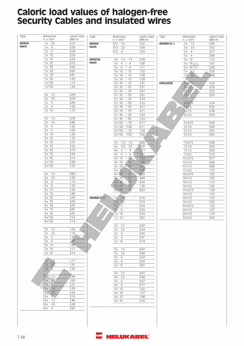
R
Caloric load values of halogen-freeSecurity Cables and insulated wires
Type dimensionn x mm2
caloric loadkWh/m
NHXHXblack
1 x 2,5 0,22
1 x 4 0,28
1 x 6 0,28
1 x 10 0,28
1 x 16 0,39
1 x 25 0,53
1 x 35 0,58
1 x 50 0,69
1 x 70 0,81
1 x 95 1,03
1 x 120 1,14
1 x 150 1,39
2 x 1,5 0,69
2 x 2,5 0,78
2 x 4 0,89
2 x 6 1,00
2 x 10 1,19
3 x 1,5 0,78
3 x 2,5 0,86
3 x 4 1,00
3 x 6 1,08
3 x 10 1,28
3 x 16 1,53
3 x 25 2,25
3 x 35 2,56
3 x 50 3,19
3 x 70 3,94
3 x 95 5,14
3 x 120 5,89
3 x 150 7,25
4 x 1,5 0,89
4 x 2,5 1,00
4 x 4 1,14
4 x 6 1,28
4 x 10 1,50
4 x 16 1,86
4 x 25 2,64
4 x 35 3,00
4 x 50 3,92
4 x 70 4,81
4 x 95 6,25
4 x 120 7,14
4 x 150 7,14
5 x 1,5 1,03
5 x 2,5 1,14
5 x 4 1,31
5 x 6 1,47
5 x 10 1,83
5 x 16 2,17
5 x 25 3,14
7 x 1,5 1,17
7 x 2,5 1,31
7 x 4 1,50
12 x 1,5 1,69
12 x 2,5 2,00
12 x 4 2,31
19 x 1,5 2,36
19 x 2,5 2,69
19 x 4 3,14
24 x 1,5 2,86
24 x 2,5 3,28
24 x 4 3,97
Type dimensionn x mm2
caloric loadkWh/m
NHXHXblack
37 x 1,5 3,92
37 x 2,5 4,69
37 x 4 5,53
NHXCHXblack
3 x 1,5/ 1,5 0,78
3 x 4 / 4 1,00
3 x 6 / 6 1,11
3 x 10 / 10 1,33
3 x 16 / 10 1,58
3 x 16 / 16 1,58
3 x 25 / 16 2,31
3 x 25 / 25 2,31
3 x 35 / 16 2,61
3 x 35 / 35 2,61
3 x 50 / 25 3,33
3 x 50 / 50 3,33
3 x 70 / 35 4,11
3 x 70 / 70 4,11
3 x 95 / 50 5,33
3 x 95 / 95 5,33
3 x 120 / 70 6,11
3 x 120 /120 6,11
3 x 150 / 70 7,50
3 x 150 /150 7,50
4 x 1,5/ 1,5 0,89
4 x 2,5/ 2,5 1,03
4 x 4 / 4 1,17
4 x 6 / 6 1,31
4 x 10 / 10 1,53
4 x 16 / 16 1,89
4 x 25 / 16 2,69
4 x 35 / 16 3,06
4 x 50 / 25 4,00
4 x 70 / 35 4,89
4 x 95 / 50 6,44
4 x 120 / 70 7,36
4 x 150 / 70 8,97
(N)HMH-O/J 1 x 1,5 0,16
1 x 2,5 0,19
1 x 4 0,23
1 x 6 0,26
1 x 10 0,33
1 x 16 0,41
2 x 1,5 0,30
2 x 2,5 0,34
2 x 4 0,43
2 x 6 0,51
2 x 10 0,74
3 x 1,5 0,33
3 x 2,5 0,40
3 x 4 0,52
3 x 6 0,64
3 x 10 0,87
4 x 1,5 0,41
4 x 2,5 0,48
4 x 4 0,67
4 x 6 0,77
4 x 10 1,02
4 x 16 1,37
4 x 25 1,98
4 x 35 2,35
Type dimensionn x mm2
caloric loadkWh/m
(N)HMH-O/J 5 x 1,5 0,45
5 x 2,5 0,52
5 x 4 0,77
5 x 6 0,89
5 x 10 1,15
5 x 16 1,67
5 x 25 2,40
7 x 1,5 0,55
7 x 2,5 0,68
HXSLHXOE 3 x 0,75 0,29
3 x 1,0 0,30
3 x 1,5 0,33
3 x 2,5 0,47
4 x 0,75 0,34
4 x 1,0 0,35
4 x 1,5 0,38
4 x 2,5 0,54
5 x 0,75 0,39
5 x 1,0 0,40
5 x 1,5 0,47
5 x 2,5 0,63
7 x 0,75 0,48
7 x 1,0 0,50
7 x 1,5 0,54
7 x 2,5 0,72
12 x 0,75 0,77
12 x 1,0 0,80
12 x 1,5 0,88
12 x 2,5 1,37
16 x 0,75 1,02
16 x 1,0 1,06
16 x 1,5 1,15
16 x 2,5 1,65
19 x 0,75 1,26
19 x 1,0 1,32
19 x 1,5 1,43
19 x 2,5 2,02
24 x 0,75 1,50
24 x 1,0 1,57
24 x 1,5 1,70
24 x 2,5 2,42
�T 66
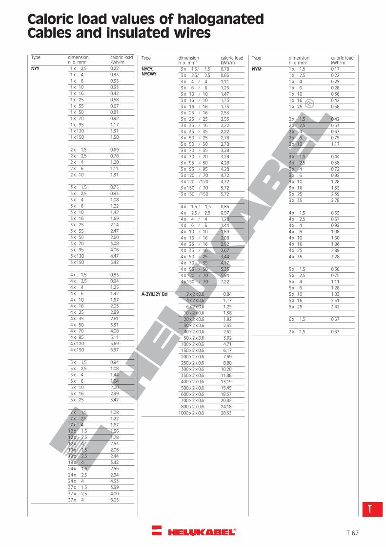
R
Caloric load values of haloganatedCables and insulated wires
Type dimensionn x mm2
caloric loadkWh/m
NYY 1 x 2,5 0,22
1 x 4 0,33
1 x 6 0,33
1 x 10 0,33
1 x 16 0,42
1 x 25 0,58
1 x 35 0,67
1 x 50 0,81
1 x 70 0,92
1 x 95 1,17
1 x 120 1,31
1 x 150 1,58
2 x 1,5 0,69
2 x 2,5 0,78
2 x 4 1,00
2 x 6 1,11
2 x 10 1,31
3 x 1,5 0,75
3 x 2,5 0,83
3 x 4 1,08
3 x 6 1,22
3 x 10 1,42
3 x 16 1,69
3 x 25 2,14
3 x 35 2,47
3 x 50 2,60
3 x 70 3,08
3 x 95 4,06
3 x 120 4,47
3 x 150 5,42
4 x 1,5 0,83
4 x 2,5 0,94
4 x 4 1,25
4 x 6 1,42
4 x 10 1,67
4 x 16 2,03
4 x 25 2,89
4 x 35 2,61
4 x 50 3,31
4 x 70 4,08
4 x 95 5,11
4 x 120 5,69
4 x 150 6,97
5 x 1,5 0,94
5 x 2,5 1,08
5 x 4 1,44
5 x 6 1,64
5 x 10 2,00
5 x 16 2,39
5 x 25 3,42
7 x 1,5 1,08
7 x 2,5 1,22
7 x 4 1,67
12 x 1,5 1,56
12 x 2,5 1,78
12 x 4 2,53
19 x 1,5 2,06
19 x 2,5 2,44
19 x 4 3,42
24 x 1,5 2,56
24 x 2,5 2,94
24 x 4 4,33
37 x 1,5 3,39
37 x 2,5 4,00
37 x 4 6,03
Type dimensionn x mm2
caloric loadkWh/m
NYCY,NYCWY
3 x 1,5/ 1,5 0,78
3 x 2,5/ 2,5 0,86
3 x 4 / 4 1,11
3 x 6 / 6 1,25
3 x 10 / 10 1,47
3 x 16 / 10 1,75
3 x 16 / 16 1,75
3 x 25 / 16 2,53
3 x 25 / 25 2,53
3 x 35 / 16 2,22
3 x 35 / 35 2,22
3 x 50 / 25 2,78
3 x 50 / 50 2,78
3 x 70 / 35 3,28
3 x 70 / 70 3,28
3 x 95 / 50 4,28
3 x 95 / 95 4,28
3 x 120 / 70 4,72
3 x 120 /120 4,72
3 x 150 / 70 5,72
3 x 150 /150 5,72
4 x 1,5 / 1,5 0,86
4 x 2,5 / 2,5 0,97
4 x 4 / 4 1,28
4 x 6 / 6 1,44
4 x 10 / 10 1,69
4 x 16 / 16 2,08
4 x 25 / 16 2,92
4 x 35 / 16 2,67
4 x 50 / 25 3,44
4 x 70 / 35 4,17
4 x 95 / 50 5,33
4 x 120 / 70 5,94
4 x 150 / 70 7,22
A-2Y(L)2Y Bd 2 x 2 x 0,6 0,84
4 x 2 x 0,6 1,17
6 x 2 x 0,6 1,25
10 x 2 x 0,6 1,38
20 x 2 x 0,6 1,92
30 x 2 x 0,6 2,32
40 x 2 x 0,6 2,62
50 x 2 x 0,6 3,02
100 x 2 x 0,6 4,71
150 x 2 x 0,6 6,17
200 x 2 x 0,6 7,69
250 x 2 x 0,6 8,88
300 x 2 x 0,6 10,20
350 x 2 x 0,6 11,88
400 x 2 x 0,6 13,19
500 x 2 x 0,6 15,45
600 x 2 x 0,6 18,57
700 x 2 x 0,6 20,82
800 x 2 x 0,6 24,18
1000 x 2 x 0,6 28,33
Type dimensionn x mm2
caloric loadkWh/m
NYM 1 x 1,5 0,17
1 x 2,5 0,22
1 x 4 0,25
1 x 6 0,28
1 x 10 0,36
1 x 16 0,42
1 x 25 0,58
2 x 1,5 0,42
2 x 2,5 0,53
2 x 4 0,67
2 x 6 0,75
2 x 10 1,17
3 x 1,5 0,44
3 x 2,5 0,58
3 x 4 0,72
3 x 6 0,92
3 x 10 1,28
3 x 16 1,53
3 x 25 2,39
3 x 35 2,78
4 x 1,5 0,53
4 x 2,5 0,67
4 x 4 0,92
4 x 6 1,08
4 x 10 1,50
4 x 16 1,86
4 x 25 2,89
4 x 35 3,28
5 x 1,5 0,58
5 x 2,5 0,75
5 x 4 1,11
5 x 6 1,28
5 x 10 1,83
5 x 16 2,31
5 x 25 3,42
6 x 1,5 0,67
7 x 1,5 0,67
�T 67
T
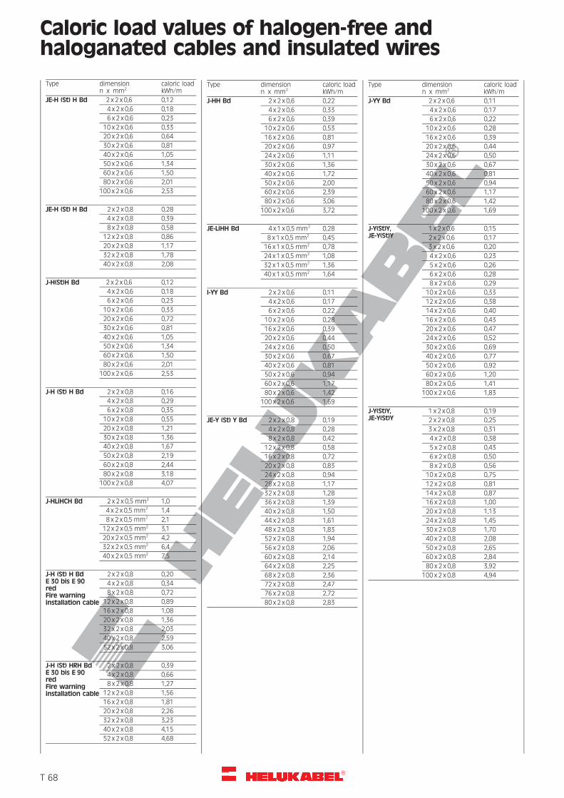
R
Caloric load values of halogen-free andhaloganated cables and insulated wires
Type dimensionn x mm2
caloric loadkWh/m
JE-H (St) H Bd 2 x 2 x 0,6 0,12
4 x 2 x 0,6 0,18
6 x 2 x 0,6 0,23
10 x 2 x 0,6 0,33
20 x 2 x 0,6 0,64
30 x 2 x 0,6 0,81
40 x 2 x 0,6 1,05
50 x 2 x 0,6 1,34
60 x 2 x 0,6 1,50
80 x 2 x 0,6 2,01
100 x 2 x 0,6 2,53
JE-H (St) H Bd 2 x 2 x 0,8 0,28
4 x 2 x 0,8 0,39
8 x 2 x 0,8 0,58
12 x 2 x 0,8 0,86
20 x 2 x 0,8 1,17
32 x 2 x 0,8 1,78
40 x 2 x 0,8 2,08
J-H(St)H Bd 2 x 2 x 0,6 0,12
4 x 2 x 0,6 0,18
6 x 2 x 0,6 0,23
10 x 2 x 0,6 0,33
20 x 2 x 0,6 0,72
30 x 2 x 0,6 0,81
40 x 2 x 0,6 1,05
50 x 2 x 0,6 1,34
60 x 2 x 0,6 1,50
80 x 2 x 0,6 2,01
100 x 2 x 0,6 2,53
J-H (St) H Bd 2 x 2 x 0,8 0,16
4 x 2 x 0,8 0,29
6 x 2 x 0,8 0,35
10 x 2 x 0,8 0,55
20 x 2 x 0,8 1,21
30 x 2 x 0,8 1,36
40 x 2 x 0,8 1,67
50 x 2 x 0,8 2,19
60 x 2 x 0,8 2,44
80 x 2 x 0,8 3,18
100 x 2 x 0,8 4,07
J-HLiHCH Bd 2 x 2 x 0,5 mm2 1,0
4 x 2 x 0,5 mm2 1,4
8 x 2 x 0,5 mm2 2,1
12 x 2 x 0,5 mm2 3,1
20 x 2 x 0,5 mm2 4,2
32 x 2 x 0,5 mm2 6,4
40 x 2 x 0,5 mm2 7,5
J-H (St) H BdE 30 bis E 90redFire warninginstallation cable
2 x 2 x 0,8 0,20
4 x 2 x 0,8 0,34
8 x 2 x 0,8 0,72
12 x 2 x 0,8 0,89
16 x 2 x 0,8 1,08
20 x 2 x 0,8 1,36
32 x 2 x 0,8 2,03
40 x 2 x 0,8 2,59
52 x 2 x 0,8 3,06
J-H (St) HRH BdE 30 bis E 90redFire warninginstallation cable
2 x 2 x 0,8 0,39
4 x 2 x 0,8 0,66
8 x 2 x 0,8 1,27
12 x 2 x 0,8 1,56
16 x 2 x 0,8 1,81
20 x 2 x 0,8 2,26
32 x 2 x 0,8 3,23
40 x 2 x 0,8 4,15
52 x 2 x 0,8 4,68
Type dimensionn x mm2
caloric loadkWh/m
J-HH Bd 2 x 2 x 0,6 0,22
4 x 2 x 0,6 0,33
6 x 2 x 0,6 0,39
10 x 2 x 0,6 0,53
16 x 2 x 0,6 0,81
20 x 2 x 0,6 0,97
24 x 2 x 0,6 1,11
30 x 2 x 0,6 1,36
40 x 2 x 0,6 1,72
50 x 2 x 0,6 2,00
60 x 2 x 0,6 2,39
80 x 2 x 0,6 3,06
100 x 2 x 0,6 3,72
JE-LiHH Bd 4 x 1 x 0,5 mm2 0,28
8 x 1 x 0,5 mm2 0,45
16 x 1 x 0,5 mm2 0,78
24 x 1 x 0,5 mm2 1,08
32 x 1 x 0,5 mm2 1,36
40 x 1 x 0,5 mm2 1,64
I-YY Bd 2 x 2 x 0,6 0,11
4 x 2 x 0,6 0,17
6 x 2 x 0,6 0,22
10 x 2 x 0,6 0,28
16 x 2 x 0,6 0,39
20 x 2 x 0,6 0,44
24 x 2 x 0,6 0,50
30 x 2 x 0,6 0,67
40 x 2 x 0,6 0,81
50 x 2 x 0,6 0,94
60 x 2 x 0,6 1,17
80 x 2 x 0,6 1,42
100 x 2 x 0,6 1,69
JE-Y (St) Y Bd 2 x 2 x 0,8 0,19
4 x 2 x 0,8 0,28
8 x 2 x 0,8 0,42
12 x 2 x 0,8 0,58
16 x 2 x 0,8 0,72
20 x 2 x 0,8 0,83
24 x 2 x 0,8 0,94
28 x 2 x 0,8 1,17
32 x 2 x 0,8 1,28
36 x 2 x 0,8 1,39
40 x 2 x 0,8 1,50
44 x 2 x 0,8 1,61
48 x 2 x 0,8 1,83
52 x 2 x 0,8 1,94
56 x 2 x 0,8 2,06
60 x 2 x 0,8 2,14
64 x 2 x 0,8 2,25
68 x 2 x 0,8 2,36
72 x 2 x 0,8 2,47
76 x 2 x 0,8 2,72
80 x 2 x 0,8 2,83
Type dimensionn x mm2
caloric loadkWh/m
J-YY Bd 2 x 2 x 0,6 0,11
4 x 2 x 0,6 0,17
6 x 2 x 0,6 0,22
10 x 2 x 0,6 0,28
16 x 2 x 0,6 0,39
20 x 2 x 0,6 0,44
24 x 2 x 0,6 0,50
30 x 2 x 0,6 0,67
40 x 2 x 0,6 0,81
50 x 2 x 0,6 0,94
60 x 2 x 0,6 1,17
80 x 2 x 0,6 1,42
100 x 2 x 0,6 1,69
J-Y(St)Y,JE-Y(St)Y
1 x 2 x 0,6 0,15
2 x 2 x 0,6 0,17
3 x 2 x 0,6 0,20
4 x 2 x 0,6 0,23
5 x 2 x 0,6 0,26
6 x 2 x 0,6 0,28
8 x 2 x 0,6 0,29
10 x 2 x 0,6 0,33
12 x 2 x 0,6 0,38
14 x 2 x 0,6 0,40
16 x 2 x 0,6 0,43
20 x 2 x 0,6 0,47
24 x 2 x 0,6 0,52
30 x 2 x 0,6 0,69
40 x 2 x 0,6 0,77
50 x 2 x 0,6 0,92
60 x 2 x 0,6 1,20
80 x 2 x 0,6 1,41
100 x 2 x 0,6 1,83
J-Y(St)Y,JE-Y(St)Y
1 x 2 x 0,8 0,19
2 x 2 x 0,8 0,25
3 x 2 x 0,8 0,31
4 x 2 x 0,8 0,38
5 x 2 x 0,8 0,43
6 x 2 x 0,8 0,50
8 x 2 x 0,8 0,56
10 x 2 x 0,8 0,75
12 x 2 x 0,8 0,81
14 x 2 x 0,8 0,87
16 x 2 x 0,8 1,00
20 x 2 x 0,8 1,13
24 x 2 x 0,8 1,45
30 x 2 x 0,8 1,70
40 x 2 x 0,8 2,08
50 x 2 x 0,8 2,65
60 x 2 x 0,8 2,84
80 x 2 x 0,8 3,92
100 x 2 x 0,8 4,94
�T 68
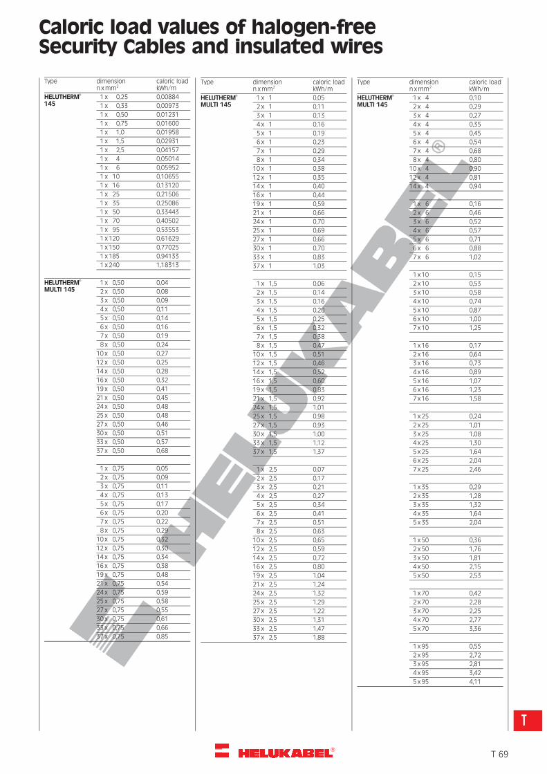
R
Caloric load values of halogen-freeSecurity Cables and insulated wires
Type dimensionn xmm2
caloric loadkWh/m
HELUTHERM�
1451 x 0,25 0,00884
1 x 0,33 0,00973
1 x 0,50 0,01231
1 x 0,75 0,01600
1 x 1,0 0,01958
1 x 1,5 0,02931
1 x 2,5 0,04157
1 x 4 0,05014
1 x 6 0,05952
1 x 10 0,10655
1 x 16 0,13120
1 x 25 0,21506
1 x 35 0,25086
1 x 50 0,33443
1 x 70 0,40502
1 x 95 0,53553
1 x 120 0,61629
1 x 150 0,77025
1 x 185 0,94133
1 x 240 1,18313
HELUTHERM�
MULTI 1451 x 0,50 0,04
2 x 0,50 0,08
3 x 0,50 0,09
4 x 0,50 0,11
5 x 0,50 0,14
6 x 0,50 0,16
7 x 0,50 0,19
8 x 0,50 0,24
10 x 0,50 0,27
12 x 0,50 0,25
14 x 0,50 0,28
16 x 0,50 0,32
19 x 0,50 0,41
21 x 0,50 0,45
24 x 0,50 0,48
25 x 0,50 0,48
27 x 0,50 0,46
30 x 0,50 0,51
33 x 0,50 0,57
37 x 0,50 0,68
1 x 0,75 0,05
2 x 0,75 0,09
3 x 0,75 0,11
4 x 0,75 0,13
5 x 0,75 0,17
6 x 0,75 0,20
7 x 0,75 0,22
8 x 0,75 0,29
10 x 0,75 0,32
12 x 0,75 0,30
14 x 0,75 0,34
16 x 0,75 0,38
19 x 0,75 0,48
21 x 0,75 0,54
24 x 0,75 0,59
25 x 0,75 0,58
27 x 0,75 0,55
30 x 0,75 0,61
33 x 0,75 0,66
37 x 0,75 0,85
Type dimensionn xmm2
caloric loadkWh/m
HELUTHERM�
MULTI 1451 x 1 0,05
2 x 1 0,11
3 x 1 0,13
4 x 1 0,16
5 x 1 0,19
6 x 1 0,23
7 x 1 0,29
8 x 1 0,34
10 x 1 0,38
12 x 1 0,35
14 x 1 0,40
16 x 1 0,44
19 x 1 0,59
21 x 1 0,66
24 x 1 0,70
25 x 1 0,69
27 x 1 0,66
30 x 1 0,70
33 x 1 0,83
37 x 1 1,03
1 x 1,5 0,06
2 x 1,5 0,14
3 x 1,5 0,16
4 x 1,5 0,20
5 x 1,5 0,25
6 x 1,5 0,32
7 x 1,5 0,38
8 x 1,5 0,47
10 x 1,5 0,51
12 x 1,5 0,46
14 x 1,5 0,52
16 x 1,5 0,60
19 x 1,5 0,83
21 x 1,5 0,92
24 x 1,5 1,01
25 x 1,5 0,98
27 x 1,5 0,93
30 x 1,5 1,00
33 x 1,5 1,12
37 x 1,5 1,37
1 x 2,5 0,07
2 x 2,5 0,17
3 x 2,5 0,21
4 x 2,5 0,27
5 x 2,5 0,34
6 x 2,5 0,41
7 x 2,5 0,51
8 x 2,5 0,63
10 x 2,5 0,65
12 x 2,5 0,59
14 x 2,5 0,72
16 x 2,5 0,80
19 x 2,5 1,04
21 x 2,5 1,24
24 x 2,5 1,32
25 x 2,5 1,29
27 x 2,5 1,22
30 x 2,5 1,31
33 x 2,5 1,47
37 x 2,5 1,88
Type dimensionn xmm2
caloric loadkWh/m
HELUTHERM�
MULTI 1451 x 4 0,10
2 x 4 0,29
3 x 4 0,27
4 x 4 0,35
5 x 4 0,45
6 x 4 0,54
7 x 4 0,68
8 x 4 0,80
10 x 4 0,90
12 x 4 0,81
14 x 4 0,94
1 x 6 0,16
2 x 6 0,46
3 x 6 0,52
4 x 6 0,57
5 x 6 0,71
6 x 6 0,88
7 x 6 1,02
1 x 10 0,15
2 x 10 0,53
3 x 10 0,58
4 x 10 0,74
5 x 10 0,87
6 x 10 1,00
7 x 10 1,25
1 x 16 0,17
2 x 16 0,64
3 x 16 0,73
4 x 16 0,89
5 x 16 1,07
6 x 16 1,23
7 x 16 1,58
1 x 25 0,24
2 x 25 1,01
3 x 25 1,08
4 x 25 1,30
5 x 25 1,64
6 x 25 2,04
7 x 25 2,46
1 x 35 0,29
2 x 35 1,28
3 x 35 1,32
4 x 35 1,64
5 x 35 2,04
1 x 50 0,36
2 x 50 1,76
3 x 50 1,81
4 x 50 2,15
5 x 50 2,53
1 x 70 0,42
2 x 70 2,28
3 x 70 2,25
4 x 70 2,77
5 x 70 3,36
1 x 95 0,55
2 x 95 2,72
3 x 95 2,81
4 x 95 3,42
5 x 95 4,11
�T 69
T
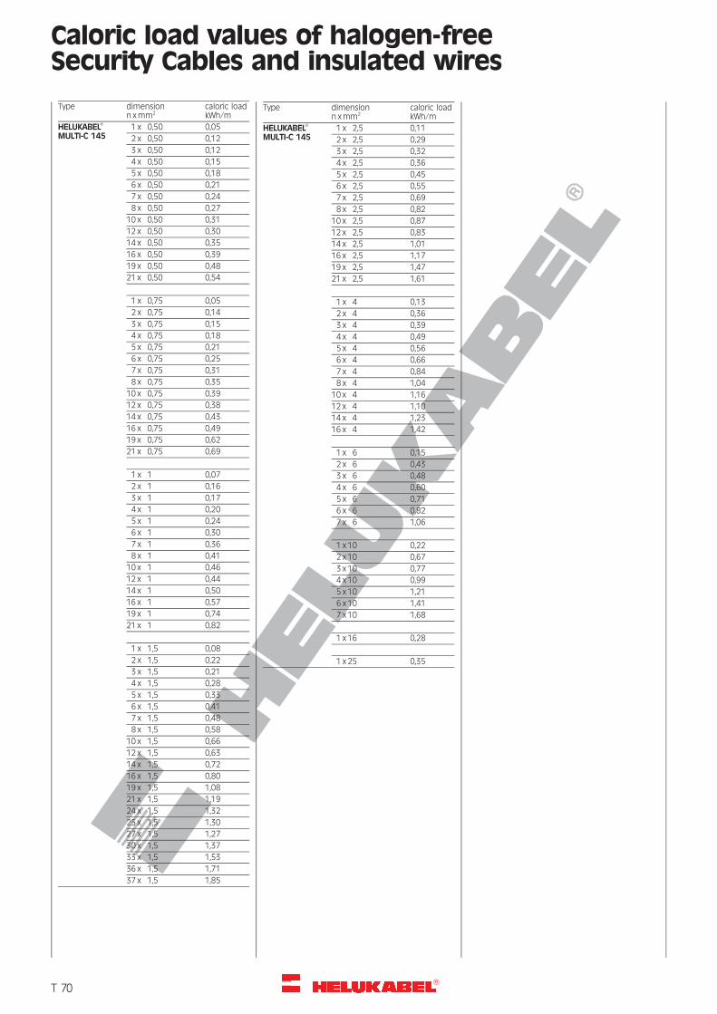
R
Caloric load values of halogen-freeSecurity Cables and insulated wires
Type dimensionn xmm2
caloric loadkWh/m
HELUKABEL�
MULTI-C 1451 x 0,50 0,05
2 x 0,50 0,12
3 x 0,50 0,12
4 x 0,50 0,15
5 x 0,50 0,18
6 x 0,50 0,21
7 x 0,50 0,24
8 x 0,50 0,27
10 x 0,50 0,31
12 x 0,50 0,30
14 x 0,50 0,35
16 x 0,50 0,39
19 x 0,50 0,48
21 x 0,50 0,54
1 x 0,75 0,05
2 x 0,75 0,14
3 x 0,75 0,15
4 x 0,75 0,18
5 x 0,75 0,21
6 x 0,75 0,25
7 x 0,75 0,31
8 x 0,75 0,35
10 x 0,75 0,39
12 x 0,75 0,38
14 x 0,75 0,43
16 x 0,75 0,49
19 x 0,75 0,62
21 x 0,75 0,69
1 x 1 0,07
2 x 1 0,16
3 x 1 0,17
4 x 1 0,20
5 x 1 0,24
6 x 1 0,30
7 x 1 0,36
8 x 1 0,41
10 x 1 0,46
12 x 1 0,44
14 x 1 0,50
16 x 1 0,57
19 x 1 0,74
21 x 1 0,82
1 x 1,5 0,08
2 x 1,5 0,22
3 x 1,5 0,21
4 x 1,5 0,28
5 x 1,5 0,33
6 x 1,5 0,41
7 x 1,5 0,48
8 x 1,5 0,58
10 x 1,5 0,66
12 x 1,5 0,63
14 x 1,5 0,72
16 x 1,5 0,80
19 x 1,5 1,08
21 x 1,5 1,19
24 x 1,5 1,32
25 x 1,5 1,30
27 x 1,5 1,27
30 x 1,5 1,37
33 x 1,5 1,53
36 x 1,5 1,71
37 x 1,5 1,85
Type dimensionn xmm2
caloric loadkWh/m
HELUKABEL�
MULTI-C 1451 x 2,5 0,11
2 x 2,5 0,29
3 x 2,5 0,32
4 x 2,5 0,36
5 x 2,5 0,45
6 x 2,5 0,55
7 x 2,5 0,69
8 x 2,5 0,82
10 x 2,5 0,87
12 x 2,5 0,83
14 x 2,5 1,01
16 x 2,5 1,17
19 x 2,5 1,47
21 x 2,5 1,61
1 x 4 0,13
2 x 4 0,36
3 x 4 0,39
4 x 4 0,49
5 x 4 0,56
6 x 4 0,66
7 x 4 0,84
8 x 4 1,04
10 x 4 1,16
12 x 4 1,10
14 x 4 1,23
16 x 4 1,42
1 x 6 0,15
2 x 6 0,43
3 x 6 0,48
4 x 6 0,60
5 x 6 0,71
6 x 6 0,82
7 x 6 1,06
1 x 10 0,22
2 x 10 0,67
3 x 10 0,77
4 x 10 0,99
5 x 10 1,21
6 x 10 1,41
7 x 10 1,68
1 x 16 0,28
1 x 25 0,35
�T 70
R
Information and Installation Instructionsfor UL and CSA cables
UL/CSA cables must be protected against mechan-ical, thermal and chemical damages.
Installation in switchboards and control boards
* Inside switchboards, flexible single core cablesmust be installed in cable channels of plastics
* As american cables are not so flexible, the mini-mum bending radius must be taken into consid-eration during flexible installation.
For connections on machinery and equipment
* Permissible tube and conduit-1 :minimum-1 = 1/2“ (inch)maximum-1 = 4“ (inch)Minimum wall-thickness of the conduit = 1,9 mm
* Normal steel armoured tubes with transitionsocket PG-NPT is used. Further metal cablechannels must also be used.
* The cables are permitted to be filled with onlymax. 50% cross-section of the cable channel.
* Flexible single cores must be installed in PVCtubes inside the conduits.
* If connectors are used, both the main and thecontrol cables should be installed separately.
Delivery program:
* PVC tubes
* Metal tubes and glands
* Fixing material
* Steel armoured tubes.
Cable Channels
* Cable channels in switchboards must be madeout of a flame resistant PVC and must haveenough spare space.
* Cable channels on machineries and equipmentmust be made out of metal. They must also beclosed and oil resistant.
Cable identification
* Cable identification is achieved through continu-ous numbers, letters or number/letter combina-tion. The beginning and end of the cable havethe same identification system.
Cable connections to apparatus
* Main and Control cables
It is depending on the type of connection to theapparatus if screw or press clamps are used.
* In USA, it is normal to install cables without usingcable lugs or cable crushing socket. The connec-tion is only possible with the UL-wires sizes. Thesesizes are not designed with fine wire strandingmake-up.
Conductor cross-section
General rules minimumcross-section for
* Motor Cables AWG 14* Control Cables
– in switchboards AWG 18
– in the installed system AWG 16
This rule does not apply to electronic devices andsystems.
In case, the electronic cables and other circuits areinstalled together, all cables must be set formaximum voltage.
Colour identification
* BlackFor main circuits, control- and subcircuits, directconnected to main voltage.* BlueFor direct voltage- (d. c.), control- and subcircuits,which are connected to the main circuit.* RedFor alternating voltage (a. c.), control and subcircuits.* Yellow or brownFor interlock circuits from an external power source.* White or greyFor current conveying earthed conductors at main,control and subcircuits.* Green or green-yellowFor insulated earth-connectors as protectiveconductor.
Motor-driving voltages200 / 230 / 460 / 575 V, 60 Hz
Driving voltageNormally the driving voltage is 120 V, 60 Hz or lower.Transformers must be operated with separate wind-ings.
�T 71
T
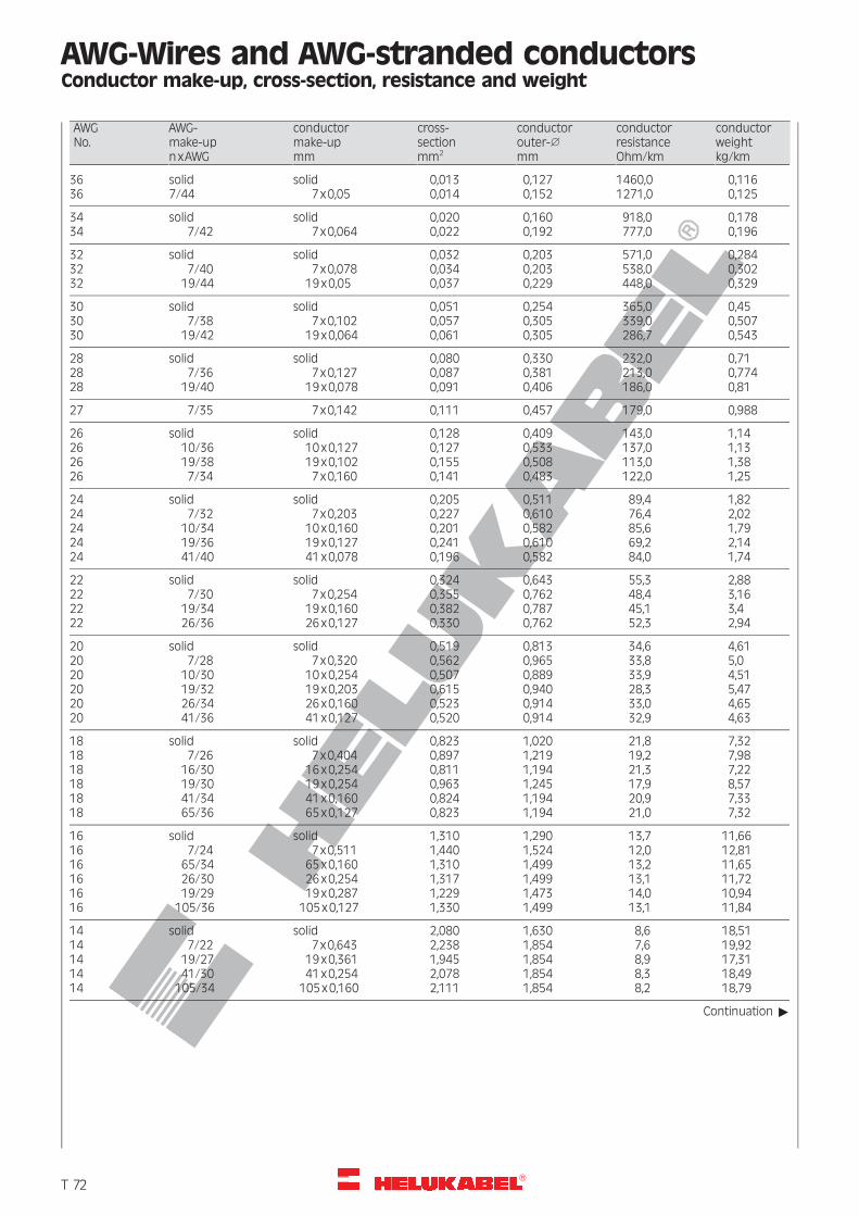
R
AWG-Wires and AWG-stranded conductorsConductor make-up, cross-section, resistance and weight
AWGNo.
AWG-make-upnxAWG
conductormake-upmm
cross-sectionmm2
conductorouter-1
mm
conductorresistanceOhm/km
conductorweightkg/km
3636
solid7/44
solid7x0,05
0,0130,014
0,1270,152
1460,01271,0
0,1160,125
34 solid solid 0,020 0,160 918,0 0,17834 7/42 7x0,064 0,022 0,192 777,0 0,196
32 solid solid 0,032 0,203 571,0 0,28432 7/40 7x0,078 0,034 0,203 538,0 0,30232 19/44 19x0,05 0,037 0,229 448,0 0,329
30 solid solid 0,051 0,254 365,0 0,4530 7/38 7x0,102 0,057 0,305 339,0 0,50730 19/42 19x0,064 0,061 0,305 286,7 0,543
28 solid solid 0,080 0,330 232,0 0,7128 7/36 7x0,127 0,087 0,381 213,0 0,77428 19/40 19x0,078 0,091 0,406 186,0 0,81
27 7/35 7x0,142 0,111 0,457 179,0 0,988
26 solid solid 0,128 0,409 143,0 1,1426 10/36 10x0,127 0,127 0,533 137,0 1,1326 19/38 19x0,102 0,155 0,508 113,0 1,3826 7/34 7x0,160 0,141 0,483 122,0 1,25
24 solid solid 0,205 0,511 89,4 1,8224 7/32 7x0,203 0,227 0,610 76,4 2,0224 10/34 10x0,160 0,201 0,582 85,6 1,7924 19/36 19x0,127 0,241 0,610 69,2 2,1424 41/40 41x0,078 0,196 0,582 84,0 1,74
22 solid solid 0,324 0,643 55,3 2,8822 7/30 7x0,254 0,355 0,762 48,4 3,1622 19/34 19x0,160 0,382 0,787 45,1 3,422 26/36 26x0,127 0,330 0,762 52,3 2,94
20 solid solid 0,519 0,813 34,6 4,6120 7/28 7x0,320 0,562 0,965 33,8 5,020 10/30 10x0,254 0,507 0,889 33,9 4,5120 19/32 19x0,203 0,615 0,940 28,3 5,4720 26/34 26x0,160 0,523 0,914 33,0 4,6520 41/36 41x0,127 0,520 0,914 32,9 4,63
18 solid solid 0,823 1,020 21,8 7,3218 7/26 7x0,404 0,897 1,219 19,2 7,9818 16/30 16x0,254 0,811 1,194 21,3 7,2218 19/30 19x0,254 0,963 1,245 17,9 8,5718 41/34 41x0,160 0,824 1,194 20,9 7,3318 65/36 65x0,127 0,823 1,194 21,0 7,32
16 solid solid 1,310 1,290 13,7 11,6616 7/24 7x0,511 1,440 1,524 12,0 12,8116 65/34 65x0,160 1,310 1,499 13,2 11,6516 26/30 26x0,254 1,317 1,499 13,1 11,7216 19/29 19x0,287 1,229 1,473 14,0 10,9416 105/36 105x0,127 1,330 1,499 13,1 11,84
14 solid solid 2,080 1,630 8,6 18,5114 7/22 7x0,643 2,238 1,854 7,6 19,9214 19/27 19x0,361 1,945 1,854 8,9 17,3114 41/30 41x0,254 2,078 1,854 8,3 18,4914 105/34 105x0,160 2,111 1,854 8,2 18,79
Continuation "
�T 72
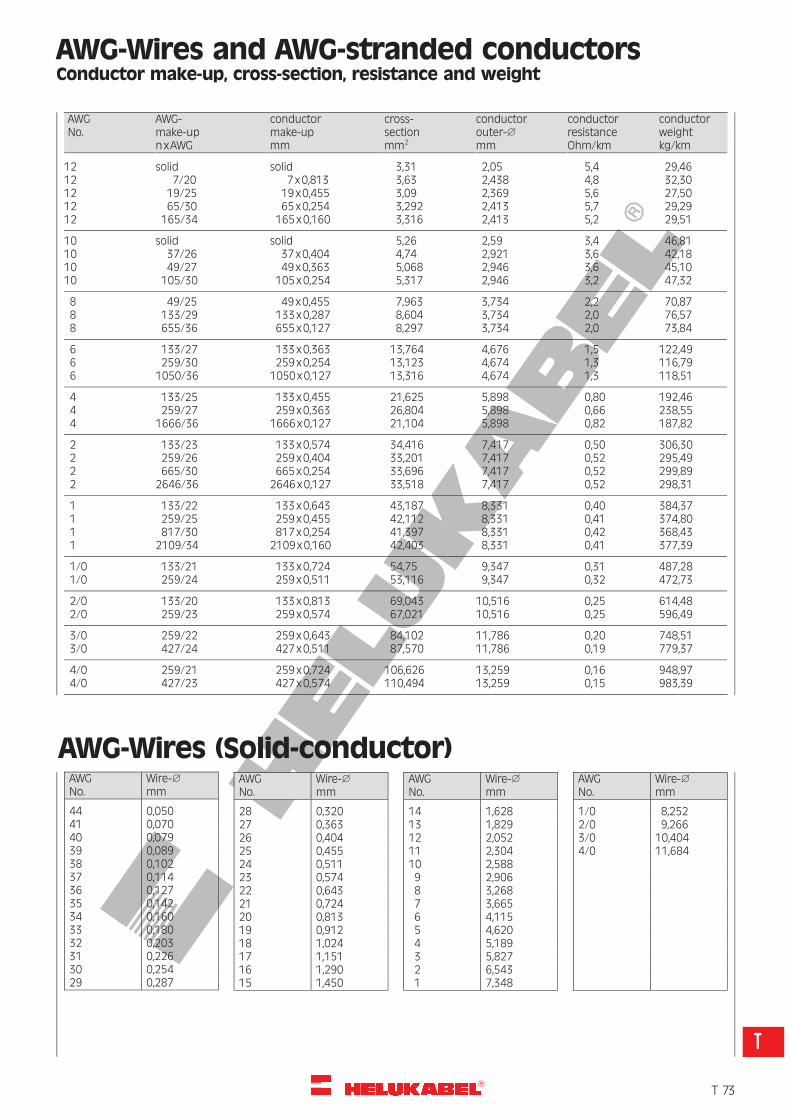
R
AWG-Wires and AWG-stranded conductorsConductor make-up, cross-section, resistance and weight
AWGNo.
AWG-make-upnxAWG
conductormake-upmm
cross-sectionmm2
conductorouter-1
mm
conductorresistanceOhm/km
conductorweightkg/km
12 solid solid 3,31 2,05 5,4 29,4612 7/20 7x0,813 3,63 2,438 4,8 32,3012 19/25 19x0,455 3,09 2,369 5,6 27,5012 65/30 65x0,254 3,292 2,413 5,7 29,2912 165/34 165x0,160 3,316 2,413 5,2 29,51
10 solid solid 5,26 2,59 3,4 46,8110 37/26 37x0,404 4,74 2,921 3,6 42,1810 49/27 49x0,363 5,068 2,946 3,6 45,1010 105/30 105x0,254 5,317 2,946 3,2 47,32
8 49/25 49x0,455 7,963 3,734 2,2 70,878 133/29 133x0,287 8,604 3,734 2,0 76,578 655/36 655x0,127 8,297 3,734 2,0 73,84
6 133/27 133x0,363 13,764 4,676 1,5 122,496 259/30 259x0,254 13,123 4,674 1,3 116,796 1050/36 1050x0,127 13,316 4,674 1,3 118,51
4 133/25 133x0,455 21,625 5,898 0,80 192,464 259/27 259x0,363 26,804 5,898 0,66 238,554 1666/36 1666x0,127 21,104 5,898 0,82 187,82
2 133/23 133x0,574 34,416 7,417 0,50 306,302 259/26 259x0,404 33,201 7,417 0,52 295,492 665/30 665x0,254 33,696 7,417 0,52 299,892 2646/36 2646x0,127 33,518 7,417 0,52 298,31
1 133/22 133x0,643 43,187 8,331 0,40 384,371 259/25 259x0,455 42,112 8,331 0,41 374,801 817/30 817x0,254 41,397 8,331 0,42 368,431 2109/34 2109x0,160 42,403 8,331 0,41 377,39
1/0 133/21 133x0,724 54,75 9,347 0,31 487,281/0 259/24 259x0,511 53,116 9,347 0,32 472,73
2/0 133/20 133x0,813 69,043 10,516 0,25 614,482/0 259/23 259x0,574 67,021 10,516 0,25 596,49
3/0 259/22 259x0,643 84,102 11,786 0,20 748,513/0 427/24 427x0,511 87,570 11,786 0,19 779,37
4/0 259/21 259x0,724 106,626 13,259 0,16 948,974/0 427/23 427x0,574 110,494 13,259 0,15 983,39
AWG-Wires (Solid-conductor)AWGNo.
Wire-1
mm
44 0,05041 0,07040 0,07939 0,08938 0,10237 0,11436 0,12735 0,14234 0,16033 0,18032 0,20331 0,22630 0,25429 0,287
AWGNo.
Wire-1
mm
28 0,32027 0,36326 0,40425 0,45524 0,51123 0,57422 0,64321 0,72420 0,81319 0,91218 1,02417 1,15116 1,29015 1,450
AWGNo.
Wire-1
mm
14 1,62813 1,82912 2,05211 2,30410 2,5889 2,9068 3,2687 3,6656 4,1155 4,6204 5,1893 5,8272 6,5431 7,348
AWGNo.
Wire-1
mm
1/0 8,2522/0 9,2663/0 10,4044/0 11,684
�T 73
T
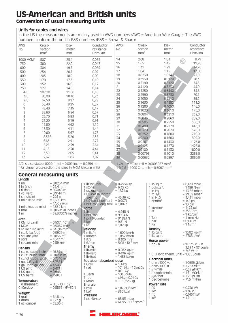
R
US-American and British unitsConversion of usual measuring units
Units for cables and wiresIn the US the measurements are mainly used in AWG-numbers (AWG = American Wire Gauge). The AWG-numbers conform the british B&S-numbers (B&S = Brown & Sharp).
AWGNo.
Cross-sectionmm2
Dia-metermm
ConductorresistanceOhm/km
1000 MCM* 507 25,4 0,035750 380 22,0 0,047600 304 19,7 0,059500 254 20,7 0,07400 203 18,9 0,09350 178 17,3 0,10300 152 16,0 0,12250 127 14,6 0,14
4/0 107,20 11,68 0,183/0 85,00 10,40 0,232/0 67,50 9,27 0,290 53,40 8,25 0,371 42,40 7,35 0,472 33,60 6,54 0,573 26,70 5,83 0,714 21,20 5,19 0,915 16,80 4,62 1,126 13,30 4,11 1,447 10,60 3,67 1,788 8,366 3,26 2,369 6,63 2,91 2,77
10 5,26 2,59 3,6411 4,15 2,30 4,4412 3,30 2,05 5,4113 2,62 1,83 7,02
4/0 is also stated: 0000; 1 mil = 0,001 inch = 0,0254 mm* for bigger cross-section the sizes in MCM (circular mils)
AWGNo.
Cross-sectionmm2
Dia-metermm
ConductorresistanceOhm/km
14 2,08 1,63 8,7915 1,65 1,45 11,2016 1,31 1,29 14,7017 1,04 1,15 17,8018 0,8230 1,0240 23,019 0,6530 0,9120 28,320 0,5190 0,8120 34,521 0,4120 0,7230 44,022 0,3250 0,6440 54,823 0,2590 0,5730 70,124 0,2050 0,5110 89,225 0,1630 0,4550 111,026 0,1280 0,4050 146,027 0,1020 0,3610 176,028 0,0804 0,3210 232,029 0,0646 0,2860 282,030 0,0503 0,2550 350,031 0,0400 0,2270 446,032 0,0320 0,2020 578,033 0,0252 0,1800 710,034 0,0200 0,1600 899,035 0,0161 0,1430 1125,036 0,0123 0,1270 1426,037 0,0100 0,1130 1800,038 0,00795 0,1010 2255,039 0,00632 0,0897 2860,0
1 CM = 1 Circ. mil. = 0,0005067 mm2
1 MCM = 1000 Circ. mils = 0,5067 mm2
General measuring unitsLength1 mil = 0,0254 mm1 in (inch) = 25,4 mm1 ft (foot) = 0,3048 m1 yd (yard) = 0,9144 m1 ch (chain) = 20,1 m1 mile (land mile) = 1,609 km
= 1760 yards1 mile (nautic mile) = 1,852 km1 mm = 0,039370 inches1 m = 39,370079 inches
Area1 CM (circ.mil) = 0,507 ? 10–3 mm2
1 MCM = 0,5067 mm2
1 sq. inch (sq. inch) = 645,16 mm2
1 sq. ft. (sq. foot) = 0,0929 m2
1 square yard = 0,836 m2
1 acre = 4047 m2
1 square mile = 2,59 km2
Density1 cu. in. (cubic inch) = 16,39 cm3
1 cu. ft. (cubic foot) = 0,0283 m3
1 cu. yd. (cubic yard) = 0,7646 m3
1 gal. (US gallon) = 3,785 l1 gal. (brit. gallon) = 4,546 l1 US pint = 0,473 l1 US quart = 0,946 l1 US barrel = 158,8 l
TemperatureF (Fahrenheit) = (1,8 ? C) + 328C (Celsius) = 0,5556 ? (F–328 )
Weight1 grain = 64,8 mg1 dram = 1,77 g1 oz (ounce) = 28,35 g
1 lb (pound) = 0,4536 Kp1 stone = 6,35 Kp1 qu (quarter) = 12,7 Kp1 US-cwt (hundred-weight) = 45,36 Kp
1 US ton (short ton) = 0,907t1 brit. ton (long ton) = 1,016 tForce1 lb = 4,448 N1 brit. ton = 9954 N1 pdl (Poundal) = 0,1383 N1 kp = 9,81 N1 N = 1,02 kpVelocity1 mile/h = 1,609 km/h1 Knoten = 1,852 km/h1 ft/s = 0,305 m/s1 ft/min = 5,08 ? 10–3 m/sEnergy1 lb/mile = 0,282 kg/m1 lb/yard = 0,496 kg/m1 lb/foot = 1,488 kg/mRadiation absorbed dose1 Gray = 1 J/kg1 rad = 10–2 J/kg=1CentiGy
= 0,01 Gy1 Centi = 100 Joule1 rad = cJ/kg=0,01Gy1 Mrad = 1 ?106 cJ/kgEnergie1 kcal = 1,16 ?103 kWh1 kWh = 360 kcalPressure1 psi (lb/sq.) = 68,95 mbar
= 6,895 ?10–3 Nmm2
1 lb/sq. ft. = 0,478 mbar1 pdl/sq. ft. = 1,489 N/m2
1 in Hg = 33,86 mbar1 ft H2O = 29,89 mbar1 in H2O = 2,491 mbar1 N/mm2 = 145 psi
= 10 bar1 kp/mm2 = 1422 psi1 at = 736 Torr
= 1 kp/cm2
1 Torr = 1 mm Hg1 bar = 0,1 H Pa1 Pa = 1 N/m2
Density1 lb/cu. ft. = 16,02 kg/m3
1 lb/cu. in. = 27,68 t/m3
Horse power1 hp ? h = 1,0139 PS ? h
= 2,684 ? 106 Joule= 746 W ? h
1 BTU (brit. therm. unit)= 1055 Joule
Electrical units1 ohm/1000 yd = 1,0936 W/km1 ohm/1000 ft = 3,28 W/km1 mF/mile = 0,62 mF/km1 megohm/mile = 1,61 MW/km1 mmf/foot = 3,28 pF/m1 decibel/mile = 71,5 mN/m
Power rate1 PS = 0,736 kW1 kW = 1,36 PS1 hp = 0,7457 kW1 kW = 1,31 hp
�T 74
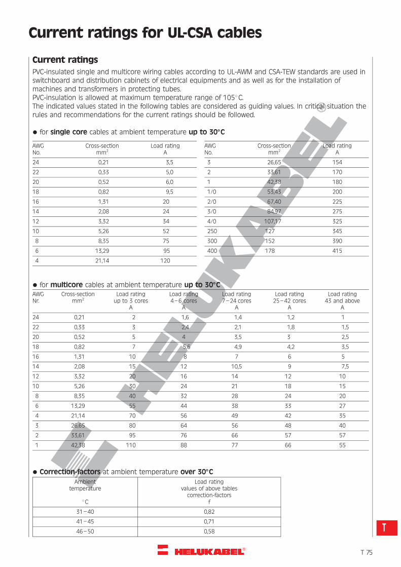
R
Current ratings for UL-CSA cables
Current ratings
PVC-insulated single and multicore wiring cables according to UL-AWM and CSA-TEW standards are used inswitchboard and distribution cabinets of electrical equipments and as well as for the installation ofmachines and transformers in protecting tubes.PVC-insulation is allowed at maximum temperature range of 1058C.The indicated values stated in the following tables are considered as guiding values. In critical situation therules and recommendations for the current ratings should be followed.
* for single core cables at ambient temperature up to 308C
AWGNo.
Cross-sectionmm2
Load ratingA
24 0,21 3,5
22 0,33 5,0
20 0,52 6,0
18 0,82 9,5
16 1,31 20
14 2,08 24
12 3,32 34
10 5,26 52
8 8,35 75
6 13,29 95
4 21,14 120
AWGNo.
Cross-sectionmm2
Load ratingA
3 26,65 154
2 33,61 170
1 42,38 180
1/0 53,43 200
2/0 67,40 225
3/0 84,97 275
4/0 107,17 325
250 127 345
300 152 390
400 178 415
* for multicore cables at ambient temperature up to 308CAWGNr.
Cross-sectionmm2
Load ratingup to 3 cores
A
Load rating4–6 cores
A
Load rating7–24 cores
A
Load rating25–42 cores
A
Load rating43 and above
A
24 0,21 2 1,6 1,4 1,2 1
22 0,33 3 2,4 2,1 1,8 1,5
20 0,52 5 4 3,5 3 2,5
18 0,82 7 5,6 4,9 4,2 3,5
16 1,31 10 8 7 6 5
14 2,08 15 12 10,5 9 7,5
12 3,32 20 16 14 12 10
10 5,26 30 24 21 18 15
8 8,35 40 32 28 24 20
6 13,29 55 44 38 33 27
4 21,14 70 56 49 42 35
3 26,65 80 64 56 48 40
2 33,61 95 76 66 57 57
1 42,38 110 88 77 66 55
* Correction-factors at ambient temperature over 308C
Ambienttemperature
8C
Load ratingvalues of above tables
correction-factorsf
31–40 0,82
41–45 0,71
46–50 0,58
�T 75
T
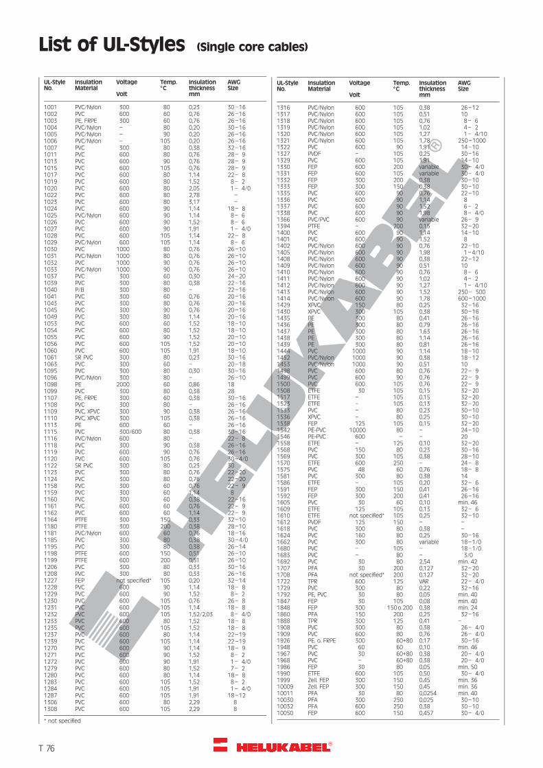
R
List of UL-Styles (Single core cables)
UL-StyleNo.
InsulationMaterial
Voltage
Volt
Temp.8C
Insulationthicknessmm
AWGSize
1001 PVC/Nylon 300 80 0,23 30–161002 PVC 600 60 0,76 26–161003 PE, FRPE 300 60 0,76 26–161004 PVC/Nylon – 80 0,20 30–161005 PVC/Nylon – 90 0,20 26–161006 PVC/Nylon – 105 0,20 26–161007 PVC 300 80 0,38 32–161011 PVC 600 80 0,76 28– 91013 PVC 600 90 0,76 28– 91015 PVC 600 105 0,76 28– 91017 PVC 600 80 1,14 22– 81019 PVC 600 80 1,52 8– 21020 PVC 600 80 2,05 1– 4/01022 PVC 600 80 2,78 –1023 PVC 600 80 3,17 –1024 PVC 600 90 1,14 18– 81025 PVC/Nylon 600 90 1,14 8– 61026 PVC 600 90 1,52 8– 61027 PVC 600 90 1,91 1– 4/01028 PVC 600 105 1,14 22– 81029 PVC/Nylon 600 105 1,14 8– 61030 PVC 1000 80 0,76 26–101031 PVC/Nylon 1000 80 0,76 26–101032 PVC 1000 90 0,76 26–101033 PVC/Nylon 1000 90 0,76 26–101037 PVC 300 60 0,30 24–201039 PVC 300 80 0,38 22–161040 P/B 300 80 – 22–161041 PVC 300 60 0,76 20–161043 PVC 300 80 0,76 20–161045 PVC 300 90 0,76 20–161049 PVC 300 80 1,14 20–161053 PVC 600 60 1,52 18–101054 PVC 600 80 1,52 18–101055 PVC 600 90 1,52 20–101056 PVC 600 105 1,52 20–101060 PVC 600 105 1,91 18–101061 SR PVC 300 80 0,23 30–161063 PVC 300 60 – 20–181095 PVC 300 80 0,30 30–161096 PVC/Nylon 300 80 – 26–101098 PE 2000 60 0,86 181099 PVC 300 80 0,38 281107 PE, FRPE 300 60 0,38 30–161108 PVC 300 80 – 26–161109 PVC, XPVC 300 90 0,38 26–161110 PVC, XPVC 300 105 0,38 26–161113 PE 600 60 – 26–161115 PVC 300/600 80 0,38 30–161116 PVC/Nylon 600 80 – 22– 81118 PVC 300 90 0,38 26–161119 PVC 600 90 0,76 26–161120 PVC 600 105 0,76 30–4/01122 SR PVC 300 80 0,23 301123 PVC 300 80 0,76 22–201124 PVC 300 80 0,76 22–201158 PVC 300 60 0,76 22– 91159 PVC 300 60 1,14 81160 PVC 300 60 0,38 22–161161 PVC 600 60 0,76 22– 91162 PVC 600 60 1,14 22– 91164 PTFE 300 150 0,33 32–101180 PTFE 300 200 0,38 28–101181 PVC/Nylon 600 60 0,76 18–161185 PVC 300 80 0,38 30–4/01195 PVC 300 80 0,38 26–141198 PTFE 600 150 0,51 26–101199 PTFE 600 200 0,51 26–101206 PVC 300 80 0,33 30–161208 PVC 300 80 0,33 26–161227 FEP not specified* 105 0,20 32–141228 PVC 600 90 1,14 18– 81229 PVC 600 90 1,52 8– 21230 PVC 600 105 0,76 26– 81231 PVC 600 105 1,14 18– 81232 PVC 600 105 1,52/2,03 8– 4/01233 PVC 600 80 1,52 18– 81235 PVC 600 105 1,52 18– 81237 PVC 600 80 1,14 22–191239 PVC 600 105 1,14 22–191270 PVC 600 90 1,14 18– 91271 PVC 600 90 1,52 8– 21272 PVC 600 90 1,91 1– 4/01279 PVC 600 80 1,52 7– 21280 PVC 600 80 1,14 18– 81283 PVC 600 105 1,52 8– 21284 PVC 600 105 1,91 1– 4/01287 PVC 600 105 1,91 18–121306 PVC 600 80 2,29 81308 PVC 600 105 2,29 8
* not specified
UL-StyleNo.
InsulationMaterial
Voltage
Volt
Temp.8C
Insulationthicknessmm
AWGSize
1316 PVC/Nylon 600 105 0,38 26–121317 PVC/Nylon 600 105 0,51 101318 PVC/Nylon 600 105 0,76 8– 61319 PVC/Nylon 600 105 1,02 4– 21320 PVC/Nylon 600 105 1,27 1– 4/101321 PVC/Nylon 600 105 1,78 250–10001322 PVC 600 90 1,91 14–101327 PVDF – 105 0,25 30–161329 PVC 600 105 1,91 14–101330 FEP 600 200 variable 30– 4/01331 FEP 600 105 variable 30– 4/01332 FEP 300 200 0,38 30–101333 FEP 300 150 0,38 30–101335 PVC 600 90 0,76 22–101336 PVC 600 90 1,14 81337 PVC 600 90 1,52 6– 21338 PVC 600 90 1,98 8– 4/01366 PVC/PVC 600 90 variable 26– 91394 PTFE – 200 0,15 32–201400 PVC 600 90 1,14 14–101401 PVC 600 90 1,52 81402 PVC/Nylon 600 90 0,76 22–101405 PVC/Nylon 600 90 1,98 1–4/101408 PVC/Nylon 600 90 0,38 22–121409 PVC/Nylon 600 90 0,51 101410 PVC/Nylon 600 90 0,76 8– 61411 PVC/Nylon 600 90 1,02 4– 21412 PVC/Nylon 600 90 1,27 1– 4/101413 PVC/Nylon 600 90 1,52 250– 5001414 PVC/Nylon 600 90 1,78 600–10001429 XPVC 150 80 0,25 32–161430 XPVC 300 105 0,38 30–161435 PE 300 80 0,41 26–161436 PE 300 80 0,79 26–161437 PE 300 80 1,63 26–161438 PE 300 80 1,14 26–161439 PE 300 80 0,81 26–161444 PVC 1000 90 1,14 18–101452 PVC/Nylon 1000 90 0,38 18–121453 PVC/Nylon 1000 90 0,51 101498 PVC 600 80 0,76 22– 91499 PVC 600 90 0,76 22– 91500 PVC 600 105 0,76 22– 91508 ETFE 30 105 0,15 32–201517 ETFE – 105 0,15 32–201523 ETFE – 105 0,13 32–201533 PVC – 80 0,23 30–101536 XPVC – 80 0,25 30–101538 FEP 125 105 0,15 32–201542 PE-PVC 10000 80 – 24–101546 PE-PVC 600 – – 201558 ETFE – 125 0,10 32–201568 PVC 150 80 0,23 30–161569 PVC 300 105 0,38 28–101570 ETFE 600 250 – 24– 81575 PVC 48 60 0,76 18– 81581 PVC 300 80 0,38 141586 ETFE – 105 0,20 32– 61591 FEP 300 150 0,41 26–161592 FEP 300 200 0,41 26–161605 PVC 30 60 0,10 min. 461609 ETFE 125 105 0,13 32– 61610 ETFE not specified* 105 0,25 32–101612 PVDF 125 150 – –1618 PVC 300 80 0,38 –1624 PVC 160 80 0,25 30–161662 PVC 300 80 variable 18–1/01680 PVC – 105 – 18–1/01683 PVC – 80 – 3/01692 PVC 30 80 2,54 min. 421707 PFA 30 200 0,127 32–201708 PFA not specified* 200 0,127 32–201722 TPR 600 125 VAR 22– 4/01729 PVC 300 80 0,22 32–161792 PE, PVC 30 80 0,05 min. 401847 FEP 30 105 0,08 min. 401848 FEP 300 150o.200 0,38 min. 241860 PFA 150 200 0,25 32–161888 TPR 300 125 0,41 –1908 PVC 300 80 0,38 26– 4/01909 PVC 600 80 0,76 26– 4/01926 PE. o. FRPE 300 60+80 0,17 30–161948 PVC 60 60 0,10 min. 461967 PVC 30 60+80 0,38 20– 4/01968 PVC – 60+80 0,38 20– 4/01986 FEP 30 80 0,05 min. 501990 ETFE 600 105 0,50 30– 4/01999 Zell. FEP 300 150 0,45 min. 3610009 Zell. FEP 300 150 0,45 min. 3610011 PFA 30 80 0,0254 min. 4010030 PFA 300 250 0,025 30–1010032 PFA 600 250 0,38 30–1010050 FEP 600 150 0,457 30– 4/0
�T 76
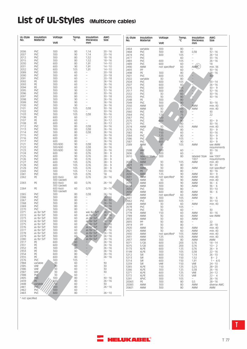
R
List of UL-Styles (Multicore cables)
UL-StyleNo.
InsulationMaterial
Voltage
Volt
Temp.8C
Insulationthicknessmm
AWGSize
2006 PVC 300 80 1,14 20–162007 PVC 300 90 1,14 20–162012 PVC 300 80 1,52 18–162015 PVC 300 80 1,52 18–162030 PVC 600 80 1,91 14–102031 PVC 600 90 1,91 14–102032 PVC 600 105 1,91 14–102089 PVC 300 60 – 20–182090 PVC 300 60 – 20–182091 PVC 300 60 – 20–182092 PE 300 60 – 26–162093 PE 300 60 – 26–162094 PE 300 60 – 26–162095 PVC 300 90 – 32–162096 PVC 300 80 – 30–162097 PVC 300 80 – 30–182098 PVC 300 90 – 26–162099 PVC 300 90 – 26–162100 PVC 300 90 – 26–162101 PVC 300 105 0,38 30–162102 PVC 300 105 – 30–162103 PVC 300 105 0,38 30–162106 PE 600 60 – 26–122107 PE 600 60 – 26–122108 PE 600 60 – 26–122112 PVC 300 80 0,38 26–162113 PVC 300 80 0,38 26–162114 PVC 300 80 0,38 26–162115 PVC 600 80 – 26–162116 PVC 600 80 – 26–162117 PVC 600 80 – 26–162121 PVC 300/600 90 0,38 26–162122 PVC 300/600 90 0,38 26–162123 PVC 300/600 90 0,38 26–162124 PVC 600 90 0,76 28– 92125 PVC 600 90 0,76 28– 92126 PVC 600 90 0,76 28– 92127 PVC 600 105 0,76 28– 92128 PVC 600 105 0,76 28– 92129 PVC 600 105 0,76 28– 92243 PVC 300 105 1,14 20–162261 PVC 300 105 0,76 182262 PE 600 (Isol.)
300 (Jacket)60 0,76 26–16
2263 PE 600 (Isol.)300 (Jacket)
60 0,76 26–16
2264 PE 600 (Isol.)300 (Jacket)
60 0,76 26–16
2265 PVC 300 80 0,38 26–162266 PVC 300 80 – 26–162267 PVC 300 80 – 36–302268 PVC 300 80 – 26–162269 PVC 300 80 – 26–162270 PVC 300 80 – 26–162271 as for SVT 300 60 wie fur SVT 26–162272 as for SVT 300 60 as for SVT 26–162273 as for SVT 300 60 as for SVT 26–162274 as for SVT 300 60 as for SVT 26–162275 as for SVT 300 60 as for SVT 26–162276 as for SVT 300 60 as for SVT 26–162277 as for SVT 300 60 as for SVT 26–162278 as for SVT 300 60 as for SVT 26–162279 as for SVT 300 60 as for SVT 26–162280 as for SVT 300 60 as for SVT 26–162317 PE 600 60 – 26–162351 PE 600 80 – 26–162352 PE 300 80 – 26–162353 PE 300 80 – 26–162354 PE 600 80 – 26–162355 PE 600 80 – 26–162376 PVC 300 105 – –2384 variable 30 60 – 302385 VAR 30 60 – 302386 VAR 30 60 – 302387 VAR 30 60 – 302388 PVC 30 60 – –2405 PVC 300 80 – 30–162439 PE 600 80 – 26–162448 variable 30 60 – 302461 PVC 300 80 – 26–162462 PVC 300 60 – –2463 PVC 600 80 – 26–10
* not specified
UL-StyleNo.
InsulationMaterial
Voltage
Volt
Temp.8C
Insulationthicknessmm
AWGSize
2464 variable 300 80 – 302468 PVC 300 80 0,38 32–162474 PVC 600 105 – 26–142477 PVC 60 – 33–162483 PVC 600 105 – 26–162489 PVC 600 60 – 182490 AWM not specified* 60 AWM min. 362493 PP 60 – 30–162498 PE 300 80 – 28–162501 PVC 600 105 – 302502 variable 30 80 – –2504 PVC 600 105 – 20–142507 PVC 600 60 – 26–162516 PVC 600 105 – 30– 92517 PVC 300 105 – 32–162532 PVC 30 60 – 30–162535 PVC 30 80 – 30–162548 PE 300 80 – –2549 PVC 300 90 – 30–162550 AWM 600 90 AWM min. 402551 AWM 30 105 AWM min. 402560 PVC 30 60 – 302564 PVC 125 75 – 222567 PVC 600 60 – –2570 PVC 600 80 – 30– 92571 PVC – 80 – 30–162574 AWM 30 105 AWM min. 402576 PVC 150 80 – 30– 92582 PE 150 60 – 30–162584 PVC 125 80 – 30– 92586 PVC 600 105 – 30– 92587 PVC 600 90 – 30– 92589 AWM 30 105 AWM see AWM
requirements2598 VAR 300 60 – 30–162606 PE 300 60 – 302610 labeled Style
1007300 80 labeled Style
1007see 1007requirements
2614 AWM 30 105 AWM min. 402623 PE 30 80 – 30–202626 AWM 30 80 AWM not specified*2629 PE 300 80 – 30–162630 AWM 125 90 AWM 30– 92631 AWM not specified* 90 AWM min. 402637 AWM 30 90 AWM min. 402653 AWM 600 90 AWM 36– 62654 AWM 300 90 AWM 36– 62655 PVC 300 80 – 33–102656 AWM 600 80 AWM 36– 62660 AWM not specified* 60 AWM –2661 AWM 300 105 AWM 36– 62662 PVC 600 105 – 33–102668 AWM 30 60 AWM min. 402678 PVC 30 105 – –2704 PVC 30 60 – 302778 AWM 150 60 AWM 30–162789 AWM 30 60 AWM see AWM2833 AWM 30 60 AWM –2835 PP 30 80 – 222919 PP 30 80 – 28–182920 AWM 30 60 AWM min. 402921 AWM 30 60 AWM min. 402930 AWM not specified* 105 AWM min. 402931 AWM 125 105 AWM min. 402937 AWM 300 80 AWM AWM3071 S/GB 600 200 0,76 18–143075 S/GB 600 200 0,76 10– 23173 XLPE 600 125 0,76 26– 93199 XLPE 300 105 0,38 22–163212 SiR 600 150 1,14 26–103213 SiR 600 150 1,52 8– 23214 SiR 600 150 1,91 1– 4/03239 SiR VAR 150 VAR 24–103265 XLPE 150 125 0,25 28–203266 XLPE 300 125 0,38 26–163271 XLPE 600 125 VAR 24–123272 XLPE 600 125 VAR 22– 43291 XPVC 300 105 – 26–1620063 PE 300 80 0,5 28–1620083 AWM 300 80 AWM diverse AWG20601 AWM 300 80 AWM AWM
�T 77
T
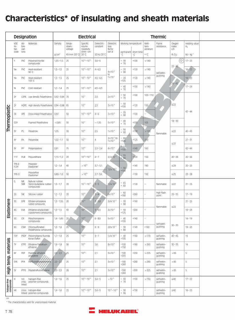
R
Characteristics* of insulating and sheath materials
halogen
-free
compounds
Hightemp.m
aterials
Thermoplastic
Elas
tomere
Designation Electrical Thermic
VDEini-tial-code
Ab-bre-viat-ions
Materials Density
g/cm3
Break-down-voltage
KV/mm (208C)
SpecificvolumeresistivityOhm ? cm208C
Dielectric-constant
50 Hz/208C
Dielectriclossfactortan d
Working temperature Melt-tem-perature
+8C
Flameresistance
OxygenindexLOI
(% O2)
Heating valueH0
MJ ? kg–1permanent8C
short time8C
Y PVC Polyvinylchloridecompounds
1,35–1,5 25 1013–1015 3,6–6
4 x 10⁻²
to1 x 10–1
– 30+ 70
+100 4140
self-extin-guishing
23–42
17–25
Yw PVC Heat-resistant908C
1,3–1,5 25 1012–1015 4–6,5 – 20+ 90
+120 4140 16–22
Yw PVC Heat-resistant1058C
1,3–1,5 25 1012–1015 4,5–6,5 – 20+105
+120 4140
24–42
16–20
Yk PVC Cold resistant 1,2–1,4 25 1012–1015 4,5–6,5– 40+ 70
+100 4140 17–24
2Y LDPE Low density Polyethylene 0,92–0,94 70 1017 2,3 2 x 10⁻⁴ – 50+ 70
+100 105–110
flammable
%22
42–44
2Y HDPE High density Polyethylene 0,94–0,98 85 1017 2,3 3 x 10⁻⁴ – 50+100 +120 130
2X VPE Cross-linked Polyethylene 0,92 50 1012–10
16 4–6 2 x 10⁻³ – 35+ 90 +100 –
O2Y Foamed Polyethylene *0,65 30 1017 *1,55 5 x 10⁻⁴ – 40+ 70 +100 105
18–30
3Y PS Polystrole 1,05 30 1016 2,5 1 x 10⁻⁴ – 50+ 80 +100 4120 %22 40–43
4Y PA Polyamide 1,02–1,1 30 1015 42 x 10–2 to1 x 10–3
– 60+105 +125 210
%22
27–31
9Y PP Polypropylene 0,91 75 1016 2,3–2,4 4 x 10⁻⁴ – 10+100 +140 160 42–44
11Y PUR Polyurethane 1,15–1,2 20 1010–1012 4–7 2,3 x 10⁻² – 55+ 80 +100 150 20–26 20–26
TPE-E(12Y)
PolyesterElastomer 1,2–1,4 40 41010 3,7–5,1
1,8 x 10⁻² – 50+100
+140 190 %29 20–25
TPE-OPolyolefineElastomer 0,89–1,0 30 41014 2,7–3,6 +130 150 %25 23–28
G NRSBR
Natural rubberStyrol-butadiene rubbercompounds
1,5–1,7 20 1012–1015 3–5 1,9 x 10⁻² – 65+ 60
+120 – flammable %22 21–25
2G SiR Silicone rubber 1,2–1,3 20 1015 3–4 6 x 10⁻³ – 60+180 +260 –
high flashpoint 25–35 17–19
3G EPR Ethylen-propylenerubber-compounds
1,3–1,55 20 1014 3–3,8 3,4 x 10⁻³ – 30+ 90
+160 –
flammable %22
21–25
4G EVA Ethylene-vinylacetatecopolymere-compounds
1,3–1,5 30 1012 5–6,5 2 x 10⁻² – 30+125
+200 – 19–23
5G CR Polychloroprenecompounds
1,4–1,65 20 1010 6–8,5 5 x 10⁻² – 40+100
+140 –
self-extin-guishing
30–35
14–19
6G CSM ChlorosulfonatedPolyethylene compounds
1,3–1,6 25 1012 6–9 2,8 x 10⁻² – 30+ 80
+140 +160 19–23
10Y PVDF Polyvinylidene fluorideKynar/Dyflor
1,7–1,9 25 1014 9–7 1,4 x 10⁻² – 40+135
+160 4170 self-extin-guishing
40–45 15
7Y ETFE Ethylene-Tetrafluor-ethylene
1,6–1,8 36 1016 2,6 8 x 10⁻⁴ –100+150
+180 4265 self-extin-guishing
30–35 14
6Y FEP Fluorine ethylenepropylene
2,0–2,3 25 1018 2,1 3 x 10⁻⁴ –100+205
+230 4225 self-extin-guishing
495 5
5YX PFA Perfluoralkoxypolymeric 2,0–2,3 25 1018 2,1 3 x 10⁻⁴ –190+260
+280 4290 self-extin-guishing
495 5
5Y PTFE Polytetrafluorethylene 2,0–2,3 20 1018 2,1 3 x 10⁻⁴ –190+260
+300 4325 self-extin-guishing
495 5
H notcrosslinked
halogen-freepolymer-compounds
1,4–1,6 25 1012–10
14 3,4–5 *10–3 – 30+ 70
+100 4130 self-extin-guishing
%40 17–22
HX crosslinked
halogen-freepolymer-compounds
1,4–1,6 25 1013–10
14 3,4–5 10–2–10–3 – 30+ 90
+150 – self-extin-guishing
%40 16–25
=* The characteristics valid for unprocessed material
T 78�
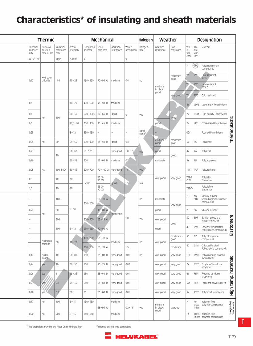
R
Characteristics* of insulating and sheath materials
halogen
-free
compounds
Hightemp.m
aterials
Elas
tomere
Thermoplastic
Thermic Mechanical Halogen Weather Designation
Thermal-conduct-ivity
W ? K–1 ? m–1
Corrosivegases incase of fire
Radiation-resistancemax
Mrad
tensilestrength
N/mm2
Elongationat break
%
Shorehardness
Abrasionresistance
Waterabsorbtion
%
halogen-free
Weatherresistance
Coldresistance
VDE-ini-tial-code
Ab-bre-viat-ions
Material
0,17Hydrogenchloride 80 10–25 130–350 70–95 (A) medium 0,4 no
medium,in black:good
moderate -good
Y PVC Polyvinylchloridecompounds
Yw PVC Heat-resistant908C
Yw PVC Heat-resistant1058C
very good YK PVC Cold resistant
0,3
no 100
10–20 400–600 43–50 (D) medium
0,1 yesgood
2Y LDPE Low density Polyethylene
0,4 20–30 500–1000 60–63 (D) good 2Y HDPE High density Polyethylene
0,3 12,5–20 300–400 40–45 (D) medium good 2X VPE Cross-linked Polyethylene
0,25 8–12 350–450 – – –condi-tional1) – 02Y Foamed Polyethylene
0,25 no 80 55–65 300–400 35–50 (D) good 0,4
yes
medium -good
moderate -good 3Y PS Polystrole
0,23
no
10
50–60 50–170 – very good 1,0–1,5 good
good
4Y PA Polyamid
0,19 20–35 300 55–60 (D) medium 0,1 moderate 9Y PP Polypropylene
0,25 100 (500) 30–45 500–700 70–100 (A) very good 1,5 yes2)
very good very good
11Y PUR Polyurethane
0,5 10 30
4300
85 (A)70 (D)
good 1,5 yes
TPE-E(12Y)
PolyesterElastomer
1,5 10 2055 (A)70 (D) TPE-O
PolyolefineElastomer
–
no
100
5–10
300–600
60–70 (A)
moderate
1,0
no moderate
very good
G NRSBR
Natural rubberStyrol-butadiene rubbercompounds
0,22 50 40–80 (A)
yes
good 2G SiR Silicone rubber
– 200 200–400 65–85 (A) very good
good
3G EPR Ethylen-propylenerubber-compounds
– 100 8–12 250–350 70–80 (A) good4G EVA Ethylene-vinylacetate
copolymere-compounds
–hydrogenchloride
50 10–20
400–700 55–70 (A)
medium no very good
moderate -good
5G CR Polychloroprenecompounds
– 350–600 60–70 (A) 1,5 moderate6G CSM Chlorosulfonated
Polyethylene compounds
0,17 hydro-fluoric
10 50–80 150 75–80 (D) very good 0,01 no very good very good 10Y PVDF Polyvinylidene fluorideKynar/Dyflor
0,24 yes 10 40–50 150 70–75 (D) very good 0,02 very good very good 7Y ETFE Ethylene-Tetrafluor-ethylene
0,26 yes 1 15–25 250 55–60 (D) very good 0,01 very good very good 6Y FEP Fluorine ethylenepropylene
0,21 yes 0,1 25–30 250 55–60 (D) very good 0,01 very good very good 5YX PFA Perfluoralkoxypolymeric
0,26 yes 0,1 80 50 55–60 (D) very good 0,01 very good very good 5Y PTFE Polytetrafluorethylene
0,17 no 100 8–13 150–250
65–95 (A)
medium
0,2–1,5 yesmediumin black:good
average
H notcrosslinked
halogen-freepolymer-compounds
0,20 no 200 8–13 150–250 medium HX cross-linked
halogen-freepolymer-compounds
1) The propellent may be e.g. Fluor-Chlor-Hydrocarbon 2) depend on the type compoundT
T 79�
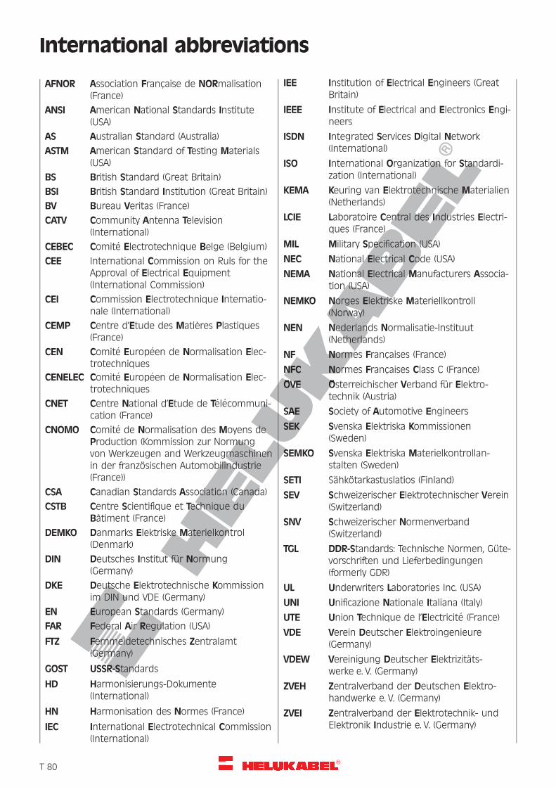
R
International abbreviations
AFNOR Association Francaise de NORmalisation(France)
ANSI American National Standards Institute(USA)
AS Australian Standard (Australia)
ASTM American Standard of Testing Materials(USA)
BS British Standard (Great Britain)
BSI British Standard Institution (Great Britain)
BV Bureau Veritas (France)
CATV Community Antenna Television(International)
CEBEC Comite Electrotechnique Belge (Belgium)
CEE International Commission on Ruls for theApproval of Electrical Equipment(International Commission)
CEI Commission Electrotechnique Internatio-nale (International)
CEMP Centre d’Etude des Matieres Plastiques(France)
CEN Comite Europeen de Normalisation Elec-trotechniques
CENELEC Comite Europeen de Normalisation Elec-trotechniques
CNET Centre National d’Etude de Telecommuni-cation (France)
CNOMO Comite de Normalisation des Moyens deProduction (Kommission zur Normungvon Werkzeugen and Werkzeugmaschinenin der franzosischen Automobilindustrie(France))
CSA Canadian Standards Association (Canada)
CSTB Centre Scientifique et Technique duBatiment (France)
DEMKO Danmarks Elektriske Materielkontrol(Denmark)
DIN Deutsches Institut fur Normung(Germany)
DKE Deutsche Elektrotechnische Kommissionim DIN und VDE (Germany)
EN European Standards (Germany)
FAR Federal Air Regulation (USA)
FTZ Fernmeldetechnisches Zentralamt(Germany)
GOST USSR-Standards
HD Harmonisierungs-Dokumente(International)
HN Harmonisation des Normes (France)
IEC International Electrotechnical Commission(International)
IEE Institution of Electrical Engineers (GreatBritain)
IEEE Institute of Electrical and Electronics Engi-neers
ISDN Integrated Services Digital Network(International)
ISO International Organization for Standardi-zation (International)
KEMA Keuring van Elektrotechnische Materialien(Netherlands)
LCIE Laboratoire Central des Industries Electri-ques (France)
MIL Military Specification (USA)
NEC National Electrical Code (USA)
NEMA National Electrical Manufacturers Associa-tion (USA)
NEMKO Norges Elektriske Materiellkontroll(Norway)
NEN Nederlands Normalisatie-Instituut(Netherlands)
NF Normes Francaises (France)
NFC Normes Francaises Class C (France)
OVE Osterreichischer Verband fur Elektro-technik (Austria)
SAE Society of Automotive Engineers
SEK Svenska Elektriska Kommissionen(Sweden)
SEMKO Svenska Elektriska Materielkontrollan-stalten (Sweden)
SETI Sahkotarkastuslatios (Finland)
SEV Schweizerischer Elektrotechnischer Verein(Switzerland)
SNV Schweizerischer Normenverband(Switzerland)
TGL DDR-Standards: Technische Normen, Gute-vorschriften und Lieferbedingungen(formerly GDR)
UL Underwriters Laboratories Inc. (USA)
UNI Unificazione Nationale Italiana (Italy)
UTE Union Technique de l’Electricite (France)
VDE Verein Deutscher Elektroingenieure(Germany)
VDEW Vereinigung Deutscher Elektrizitats-werke e. V. (Germany)
ZVEH Zentralverband der Deutschen Elektro-handwerke e. V. (Germany)
ZVEI Zentralverband der Elektrotechnik- undElektronik Industrie e. V. (Germany)
�T 80

R
Definitions: Classes of Stress (Duty) in FlexibleCables and Insulated Wires
The application of a flexible cable in certain areas as, or in, operating materials as well as for certain combi-nations of external influences that can occur in these areas, is described by the collective term “stress” or“duty”. Suitable flexible cables and insulated wires are defined in the applicable equipment standards forthe devices in question. On the basis of mechanical influences, as well the general expressions used, theterm “stress” or “duty” is divided into the following categories.
Normal stress / Ordinary duty– Normal stress is present when the cables are subject to low mechanical stresses in the areas of applica-
tion, and the risk of mechanical damage is low, as is the case to be expected in the normal use of smallto medium size equipment in domestic and commercial as well as in light industrial premises.Such equipment includes amongst others, vacuum cleaners, toasters, washing machines, refrigerators.
Low stress / Light duty– Low stress is then present when the risk of mechanical damage and mechanical stress is low in the
areas of application, as is the case to be expected for normal use of lightweight hand-held devices andlightweight operating materials in domestic households.Included in such equipment are radios, floor lamps, hairdryers, small desktop office equipment.
Very low stress / Extra light duty– Very low stress is then present when the risk of mechanical damage and mechanical stress is very low
and can be considered negligible, i.e. under those influences that are to be expected for lightweightappliances in households and offices; Cases of applications where the cables having a greater mechanicalprotection would restrict the freedom of movement by the appliance.Included in such types of appliances are electric clocks and electric shavers.
High stress / Heavy duty– High stress is then present when the risk of mechanical damage or a mechanical stress is of medium
severity appreciable, e.g. for normal use of equipment in moderately heavy branches of industry or agri-cultural workshops, and the temporary use of such at building sites.Included in such equipment are, amongst others, moderately heavy portable machinery and motors at abuilding site or in agricultural workings, large hot-water boiling installations, hand-held lamps, hoists, andfixed installations in temporary buildings.
High stress (Heavy duty) in multi-core cables– Applications as for high stress, though primarily for use in areas of manufacturing facilities including tool-
making machinery, or mechanical handling equipment. The cables can be used inside or outside build-ings for an ambient temperatures ranging from between –258C and +508C and the stabilised conductortemperatures do not exceed +608C Examples are for connecting a control unit to a production machine,connections between a control unit and a machine, e.g. in hoists or cranes where the cable length doesnot normally exceed 10 m. Longer cable lengths are permissible for fixed inter-connections.
Application: Indoor and outdoor use
The terms are in conjunction with the limiting conditions, such as for example, minimum and maximumoperating temperatures, or the influence of the ambient temperatures, understood as being limited by thedesign and intended usage. This context is defined by “the intended environment”.
Indoor use– The cables are installed or connected to an apparatus device and can be used permanently in the
building at all times, namely in “the intended environment”. The building can be used for commercial,industrial or residential purposes.
Outdoor use for a limited period– The cables may be used outdoors as “the intended environment” for short periods of time, e.g.
connected to electric lawnmowers or drills.
Permanent outdoor use– The cables are designed to resist the various stresses that can occur outdoors in “the intended environ-
ment” (including weather conditions).
�T 81
T
R
Safety Requirements in the Use of Cables andInsulated Wires
Fundamental requirements
The cables and insulated wires shall be of adequate safety for proper use in the intended manner suchthat these do not constitute any unacceptable risk to life or damage to property. The prevention of dangerto persons and property during usage and storage of operating equipment means safety to include thedetection of stress, risk and potential faults, as well as their rectification or a limitation to a minimum risklevel.Unless otherwise specified, cables and insulated wires should only be used for the conductance and distri-bution of electricity.
General requirements
The choice in the selection of cables and insulated wires should be such that the voltages and currentsprevailing in the operating equipment, a system or device used shall meet all operating conditions to beexpected.The cables shall be constructed, installed, protected, used and maintained to prevent danger as far as itsreasonably practical.
Limiting conditions
The limiting conditions in the DIN VDE and HD specifications shall be taken into account. An acceptableservice life will be attained by compliance with the limiting conditions, depending on the circuit designedunder defined conditions for use. The usable life of a permanently installed cable for power distribution islonger than that of a flexible cable.The influence by all of the factors given in the following sections must be considered as an interrelationshipand not on an individual basis.
Selection of cables and insulated wires
The choice in the selection of cables and insulated wires shall be made such that these are suitable for theoperating conditions as well as for all other external influences and compliance with the respective protec-tion class.a) Operating conditions are, for example:
– voltage
– protective measures
– grouping of cables
– current
– method of installation
– accessibility
b) External influences are, for example:
– ambient temperature
– presence of rain, water vapour or the accumulation of water
– presence of corrosive, contaminating or other chemical substances
– mechanical stresses (such as holes or sharp edges from metal constructions for example)
– animal world (such as rodents)
– plant world (such as fungal growths)
– irradiation (such as sunlight).
Note: The colour black provides a higher degree of protection than other colours.
�T 82
R
Safety Requirements in the Use of Cables andInsulated Wires
Requirements for cables
– for permanent installation, and
– for flexible applications
Requirements for fixed installation
In the normal case, cables for permanent installation have solid single wire or stranded conductors. Incertain circumstances, e.g. for greater ease of installation, the conductor may be Class 5 according to HD383 or DIN VDE 0295.Cables should not be in contact with, or close to, hot surfaces if the cables are not intended for suchconditions.Cables should not be buried directly in the earth and should be fastened by a suitable means while makingallowance for the maximum spacing between fixing points.The cable should not be damaged by any mechanical restraint used for its support . Cables which havebeen in use over longer periods of time may become damaged by movement. This can be caused by thenatural effects of ageing on the physical properties of the materials used for the insulation sheath andjacket which can become brittle with time.
For flexible applications
Flexible cables are made up conductors consisting of multiplicity of small wires and are either stranded orbunched. These cables meet either Class 5 or Class 6 of HD 383 and DIN VDE 0295.Flexible cables should be used for connections to mobile operating equipment. The length of theconnecting cable must be chosen such that response by the short-circuit protecting device is assured.The cable length should be as short as is needed for the practical application so as to reduce the risk ofmechanical damage. In cases of applications where flexible PVC-sheathed cables are permissible, the use ofspiral cables can be considered for shortening the effective length.Flexible PVC-sheathed cables are not necessarily suitable for processing further to spiral cables. Multicorecontrol cables shall be protected against permanent bending stress. Abrasion, notches and sharp bendsare to be avoided.
Except for cables for connections to permanently installed operating equipment, flexible cables should notbe permanently fixed (with the exception of heavy-duty cable designs for permanent installation intemporary facilities) unless these are contained in an enclosure affording mechanical protection. For a fixedinstallation, at least one cable should be used for “normal” stress.
Flexible cables should not be subjected to excessive straining from tensile forces, compression, twisting orkicking. This applies in particular at the point of entry into the device, and strain relief or the point ofconnection to the fixed wiring. These should not be damaged by any strain relief or clamping device atpoints to the permanent installation.
Flexible cables should not be placed under floorcoverings or carpets because there is the danger that thiscan cause thermal insulating effects, leading to increased temperatures, or that the weight of furniturefrom traffic can damage the cables.
Flexible cables should neither be in contact with, or close to, hot surfaces nor extend into the immediatevicinity of such, as they are not suitable for this purpose.
On account of their characteristics, this also applies in particular for PVC-sheathed and/or jacketed cables.The suitability of flexible cables for outdoor applications, either for short periods or continuous operation,is defined in the tables of the HD 516 and in DIN VDE Part 300.
Flexible PVC-sheathed cables are not suitable for permanent use in outdoor applications.The types of structures for PVC-sheathed cables for short-term use in outdoor applications should nothowever be operated in conditions others than these, e.g. at temperatures lower than the specifiedtemperature.
�T 83
T
R
Safety Requirements in the Use of Cables andInsulated Wires
Cables without a jacket may neither be used as a substitute for a jacketed cable nor as an extension cable.These shall principally not be used for connecting Class 2 equipment unless the cable in the constructionalstandard has been defined as a cable for extra light duty and the equipment standard explicitly permitsthis cable type.
The corresponding VDE and HD regulations shall be observed for the cables used in deep mining opera-tions, in quarrying as well as for moveable equipment, such as in cranes with spring-loaded reeling devicesfor example.
Voltage
The rated voltage for a cable is the reference voltage for which the cable is designed and which serves todefine the electrical testing requirements.The rated voltage is expressed as the ratio of two values, U0/U, whereby U0 is the effective value (r.m.s.) ofthe voltage between any insulated conductor and the “earth” (metal covering of the cable or surroundingmedium)U is the effective value (r.m.s.) between any two phase conductors of a multicore cable or of a system ofsingle core cables. In an alternating current system, the rated voltage of a cable shall be at least equal tothe nominal voltage to the value U0 and U. In direct current system, the rated voltage of the system shallnot be higher than 1,5 times that of the nominal voltage of the cable.Note: The operating voltage of a system may permanently exceed the rated voltage for the cable by 10 %.
Current carrying capacity
The nominal cross-section of each conductor should be selected such that the current carrying capacity isnot less than the maximum continuous current that flows through the conductor under normal conditionsof operation. The limiting temperature with respect to the current carrying capacity should not beexceeded for the cable insulation and sheath concerned.
Included in the defined conditions is also the method of installation for the cable used. The regulations forthe permissible current rating shall be observed here for the current.Correction factors may also be included in the values given for the load rating to allow for other conditions,such as for example:1. cable grouping2. type of overcurrent protection3. ambient temperature4. reeled / drummed cables5. thermal insulation6. frequency of the current (if other than 50 Hz)7. effects of harmonic waves
Serious damage can be caused if cables are operated for longer periods of time above those limits given inthe tables and can lead to early failure or considerable deterioration in the cable characteristics.
Thermal influences
Cables should be selected, located and installed so that the intended heat dissipation is not inhibited andthey do not present a fire hazard to adjacent materials.
The limiting temperatures for the individual cables are given separately in our catalogue. Under no circum-stances may these values be exceeded by an interaction of internal joulean heat (to the material of thecable, connections and terminals) by the ambient conditions.
�T 84
R
Safety Requirements in the Use of Cables andInsulated Wires
Mechanical stress
Allowance shall be made for all possible mechanical stress that can arise during a normal installationprocess for laying cable in order to assess the risk of mechanical damage to cables.
Tension
The following values for tension should not be exceeded for each conductor in use. This applies up to amaximum value of 1000 N for the tensile stress of all conductors unless HELUKABEL has approved limitsdeviating from this value.50 N/mm2 by permanent operation for fixed installation.15 N/mm2 for flexible cables under static tension for fixed installation that are used in current circuits.It is recommended for those cases where the above values are exceeded, that a separate strain-relievingelement or similar protection should be used. The connection of such a strain-relieving element to thecable shall be made such that the cable is not damaged.If flexible cables are subjected to dynamic tensile stress (including those due to the mass inertia,e.g. for reeling drums), the permissible tension or the fatigue life should be agreed between the user andHELUKABEL.Notes for cables which are installed vertically, without any intermediate support, can be found inDIN VDE 0298 part 300 and HD 516 S2, item 5.4.1, and Table 6.
Bending stress
The internal bending radius of a cable should be chosen such that the cable is not damaged by this.The internal bending radii are given in Table 6 of HD 516 S2 and DIN VDE 0298 part 300.The choice of bending radii smaller than specified shall be concurred with HELUKABEL.Attention shall be given when stripping the insulation that the conductor is not damaged by this as thebending characteristics will otherwise seriously deteriorate.The bending radii given apply for ambient temperatures of (20 + 10)8C. The recommendations fromHELUKABEL shall be enquired for ambient temperatures other than those given.For flexible cables and cords, particularly at terminations and at the point of entry of moveable appliances,it may be necessary to use a device which ensures that the cable is not bent to an internal bending radiusless than that specified in Table 6 of HD 516 S2 and DIN VDE 0298 part 300.
Bending too close to any internal and/or external anchorage shall be avoided.
Kink-protection sleeves or other devices shall not impede the movement of the cores within the cable.
Compression
Cables shall not be compressed to an extent that this will damage the cable.
Torsional stress
In general, flexible cables are not designed for torsional stress. In those cases where such torsional stresscannot be avoided, then the design of the cable and the installation arrangements should be agreedbetween user and HELUKABEL.
�T 85
T
R
Safety Requirements in the Use of Cables andInsulated Wires
Compatibility
The following points shall be considered in the selection and installation of cables:
– The avoidance of interference mechanical and electrical influences between adjacent circuits.
– Dissipation of heat from cables, or the chemical/physical influences from the materials used for thecables on bordering materials, such as for example, constructional and decorative materials, insulationtubes, supports, etc.
– Mutual interference by adjacent materials and the materials used for the cables. This applies for instance,for an absorption of plasticiser from PVC-sheathed cables by certain materials that are used for thermalinsulation purposes, for strapping materials or for the equipment.
Dynamic stress
The possibility should be taken into consideration of damage to cables and fastenings for these, by thedynamic forces that can be caused by any current including short-circuit currents.
Storage/Handling/Transportation
Cables that are not intended for outdoor applications should be stored in dry indoor environments. Anumber of constructional types of flexible cables are particularly susceptible to moisture, such as screenedcables for example.
The ends of the cables should be sealed for the application and the expected duration of outdoor storagein order to prevent the penetration of moisture. The temperatures given in the tables in HD 516 S2 forstorage shall be taken into account.
If the temperature of the cable falls below recommended values, then all types of mechanical stresses, inparticular vibrations, shock, impact, bending and torsional twist shall be avoided.
�T 86
R
Glossary of Terms: Cables and Wires
AAcceptance angle – The half-angle of the conewithin which incident light is totally internallyreflected by the fiber core. It is equal to arcsin (NA).
Aerial cable – A cable suspended in the air onpoles or other overhead structure.
Appliance Wire and Cable – A classification cover-ing insulated wire and cable for internal wiring ofappliances and equipment.
Armoured Cable – A cable provided with a wrap-ping of metal for mechanical protection.
ASA – Abbreviation for American Standards Associa-tion. Former name of ANSI.
ASME – Abbreviation for American Society ofMechanical Engineers.
ASTM – Abbreviation for the American Society forTesting and Materials.
ATM (Asynchronous Transfer Mode) – A newemerging data standard that uses many of thesame data rates as Fiber Channel and SONET.
Attenuation – The power drop or signal loss in acircuit, expressed in decibels (db). Generally attenua-tion increases (signal level decreases) with bothfrequency and cable length.
AWG – Abbreviation for American Wire Gauge. Astandard measurement of the size of a conductor.
AWM – Designation for Appliance Wiring Material.
BBit – A binary digit, smallest element of informationin binary system.
Bit (Binary Digit) – A basic unit for the datas of adigital transmitting system. A group of 8 Bit isusually expressed as one Byte.
Bit rate – The number of bits of data transmittedover a phone line per second.
B & S Gauge – Standard for Brown & Sharpe Gauge.The wire diameter standard is same as AWG.
Breakdown Voltage – The voltage at which theinsulation between two conductors will break down.Performed as a type test in the laboratory.
British Standard Wire Gauge – A modification ofthe Birmingham Wire Gauge and the legal standardof Great Britain for all wires. It is variously known asStandard Wire Gauge (SWG), New British Standard(NBS), English Legal Standard, and Imperial Wire Guide.
Building Wire – Insulated wires used in building forlight and power, 600 volts or less, usually notexposed to outdoor environment.
Buffer – A protective coating over an optical fibre. Asoft material extruded tightly over the fibre coating,mechanically isolates individual fibres.
BUS – A network which functions like a signal lineand is shared by a number of nodes.
CCable – Multicore stranded insulated wires underprotective sheath to conduct electrical energy e.g.power cable, telecommunication cable, installationcable, data cable etc.
Cable Core – The portion of an insulated cablelying under the protective covering.
Cable Sheath – A protecting covering over thecable core to prevent outer damages.
Capacitance (Capacity) – That property of a systemof conductors and a dielectric which permits thestorage of electricity when potential difference existsbetween the conductors. A capacitance value isalways positive.
Capacitive Coupling – Electrical interactionbetween two conductors caused by the capacitancebetween them.
CATV – Acronym for Community Antenna Television.
CEBEC – Belgium approval agency; Comite Electro-technique Belge Service de la Marque.
CEE – European standards agency; InternationalCommission on Rules for the Approval of ElectricalEquipment.
Cellular insulation – Insulating material in foamedor sponge form with the cells closed or intercon-nected.
CENELEC – European standards agency; EuropeanCommittee for Electrotechnical Norms.
Chromatic dispersion – The speed of an opticalpulse travelling in a fiber changes if its wavelengthchanges. Chromatic dispersion can be measured bythe measurement of travel time at different wave-length.
Circuit – The entire route of an electrical current. Acomplete path over which electrons can flow fromthe negative terminals of a voltage source throughparts and wires to the positive terminals of thesame voltage source.
�T 87
T
R
Glossary of Terms: Cables and Wires
Circuit Sizes – A popular term for building wiresizes 14 through 10 AWG.
Circular Mil (CM) – Used to define cross-sectionalareas of conductors. Area of a circle 1/1000 inchesin a diameter. 1 mil (0,001 inch) is equal to squaremil x 0,78540.
Cladding – A low-refractive index, glass or plasticthat surrounds the core of a fiber. Optical claddingpromotes total internal reflection for the propaga-tion of light in a fiber.
Coaxial Cable – A cable consisting of two cylindricalconductors with a common axis, separated by adielectric. The outer conductor or shield iscommonly used to prevent external radiation fromaffecting the current flowing in the inner conductor.
Coherent waves – The phenomenon related to theexistence of a correlation between the phases ofthe corresponding components of two waves orbetween the values of the phase of a given compo-nent of one wave at two instants in time or twopoints in space.
Colour Code – A system of identifying differentinsulated cores by means of colours, numbers, print-ing etc.
Concentric lay – Cable core composed of a centralcore surrounded by one or more layers of helicallylaid insulated wires or cores.
Conductor – A material capable of easily carryingan electrical conductivity. A wire or combination ofwires not insulated from one another, suitable forcarrying electric current.
Control Cable – A multi-conductor cable made foroperation in control of signal circuits.
Copolymer – A compound resulting from the poly-merization of two different monomers.
Copperweld – Copper covered steel wire. Copperand steel welded together. The trade name of FlexoWire Division (Copperweld Steel Corp.) for theircopper-clad steel conductors.
Cord – A small, flexible insulated cable.
Cord Set – Portable cords fitted with a wiring deviceat one or both ends. Cord is a small flexible insu-lated conductor or group of conductors, normallynot larger than AWG 10 – up to 4 cores.
Core – In cables, a component or assembly ofcomponents over which other materials are applied,such as additional components, shield, sheath, orarmour.
Corona – A discharge due to ionization of airaround a conductor with a potential gradientexceeding a certain critical value. A high voltageelectrical discharge that attacks insulation.
Crimp – Act of compressing a connector barrelaround a cable in order to make an electricalconnection.
Cross-linked – Setting up the chemical linksbetween the molecular chains. A form of polyethylenmaterial whose moleculars are more closely linkedto produce a greater balance of physical and elec-trical properties. (XLPE – compound)
Crosstalk – Interference caused by audio frequen-cies. Undesired electrical currents in conductorscaused by electromagnetic or electrostatic couplingfrom other conductors or from external sources.Also, leakage of optical power from one opticalconductor to another.
CSA – Abbreviation for Canadian Standards Associa-tion, a non-profit independent organization whichoperates a listing service for electrical and electronicmaterials and equipment. The Canadian counterpartof the Underwriter’s Laboratories.
Current – Flow of electricity measured in amperes.Practical unit is the ampere which represents thetransfer of one coulomb per second.
Current rating – The maximum continuous elec-trical flow of current recommended by a given wirein a given situation, expressed in amperes.
Cut off wavelength – For a singlemode fiber, thewavelength above which the fiber exhibits single-mode operation.
DdB – see decibel
D.C. – Abbreviation for direct current (D – C), Electri-city that flows in one direction only.
Decibel (dB) – One-tenth of a bel. Unit to expressdifferences of power level. Example: The decibel is10 times the common logarithm of the power ratio.It is used to express power gain in amplifiers orpower loss in passive circuits or cables.
DEMKO – Approval agency of Denmark. DenmarksElektriske Material Kontrol.
Dielectric Breakdown – The voltage required tocause an electrical failure or breakthrough of theinsulation.
�T 88
R
Glossary of Terms: Cables and Wires
Dielectric Strength – The maximum voltage insula-tion can withstand without rapture. Usuallyexpressed as a voltage gradient, e.g. volts per mil.
Dispersion – A general term for those phenomenathat cause a broadening or spreading of light as itpropagates through an optical fiber. The three typesare modal, material, and waveguide
Drain Wire – An uninsulated wire used as an earthconnection. This is generally laid over the compo-nent or under the screening, braiding etc.
Duct – An underground or overhead tube orconduit for carrying electrical cables.
EEIA – Abbreviation for Electronic Industries Associa-tion.
Elastomer – Any material that will return to itsoriginal size after stretching. Elastomer is a rubberor rubber-like material which will stretch repeatedlyto 200 percent or more and return rapidly withforce to its approximate original shape.
Electromagnetic Coupling – Energy transfer bymeans of a varying magnetic field.
Electromagnetic Induction – The production of avoltage in a coil due to a change in the number ofmagnetic lines of force (flux linkages) passingthrough the coil.
Elongation – The fractional increase in the lengthof a material stressed in tension.
EMC – Electromagnetic Compatibility (EMV).
EMF – Abbreviation for Electro Motive Force – forcedeterminating flow of electricity (voltage).
EMI – Any electrical or electromagnetic interferencethat causes undesirable response, degradation, orfailure in electronic equipment. Optical fibers neitheremit or receive EMI.
EMV – Designation for electromagnetic compatibility(EMC).
EPR – Ethylene-propylene copolymer rubber. Thecopolymer is chemically cross-linked.
ETFE – Ethylene tetrafluoroethylene
FFDDI – Fiber Distributed Data Interface. Very highspeed Computer Network working with fiber optics.
FEP – Fluorinated ethylene propylene
Ferrule – A component of a connector that holdsfiber in place and aids in its alignment, usuallycylindrical in shape with a hole through the center.
Filled Cable – A telephone cable construction inwhich the cable core is filled with a material that willprevent moisture from entering or passing throughthe cable.
Fine Stranded Wire – Stranded wire with compo-nent strands of 36 AWG or smaller.
Flame Resistance – The ability of a material not topropagate flame once the heat source is removed.
Flammability – The measure of the material’s abilityto support combustion.
Flat Cable – A cable in flat form, where the coreslying parallel longitudinally but essentially with flatsurfaces.
Foamed Plastics – Insulations having a cellularstructure.
Foils – A thin supporting film of continuous sheetsuch as plastic foil, metal foil, laminated foil etc. forstatic shielding, contacts and other electrical appli-cations.
FR-1 – A flammability rating established by Under-writers Laboratories for wires and cables that pass aspecially designed vertical flame test. This desig-nation has been replaced by VW-1.
FRNC – Flame Retardant Non Corrosive
GGauge – A term used to denote the physical size ofa wire.
Graded-index fiber – An optical fiber whose corehas a nonuniform index of refraction. The core iscomposed of concentric rings of glass whose refrac-tive indices decrease from the center axis. Thepurpose is to reduce modal dispersion and therebyincrease fiber bandwidth.
Ground Conductor – An electrical conductor forthe connection to the earth, making a completeelectrical circuit.
HHelix – A continuous spiral winding.
Henry – The unit of inductance (H).
Hertz (Hz) – A unit of measurements of thefrequency equal to one cycle per second.
High Temperature Wire and Cable – Electricalwire and cables having thermal operating character-istics of 1508C and higher.
�T 89
T
R
Glossary of Terms: Cables and Wires
Hi-Pot – A test designed to determine the highestvoltage that can be applied to a conductor withoutelectrically breaking down the insulation.
High Voltage – Generally, a wire or cable with anoperating voltage of 600 volts and above.
Hook-up Wire – Single conductor used to hook-upelectrical parts of instruments for low current andvoltage (under 1000 volts).
Hybrid Cable – Multi-conductor cable containingtwo or more types of components.
Hypalon – Du Pont’s trade name for their chlorosul-fonated polyethylene, an ozone resistant syntheticrubber (908C).
Hz – Abbreviation for Hertz.
IICEA – Abbreviation for Insulated Cable EngineersAssociation.
IEC – European Standardization agency; Interna-tional Electrotechnical Commission.
IEEE – Abbreviation for Institute of Electrical andElectronics Engineers.
Impedance – Resistance to flow of an alternatingcurrent at a particular frequency, expressed inohms. It is a combination of resistance R and re-actance X, measured in ohms.
Index profile – A graded-index optical fiber, therefractive index as a function of radius.
Induction – An influence exerted by a chargedbody or by a magnetic field on adjacent bodieswithout apparent communication.
Inductive Coupling – Crosstalk resulting from theaction of the electromagnetic field of one conductoron the other.
Insulation – A non-conducting substance, namedas dielectric, surrounding the conductor.
Interface – The two surfaces on the contact side ofboth halves of a multiple-contact connector whichface each other when the connector is assembled.Common interconnection point for devices, e.g.RS232 Interface: Mouse-Personalcomputer.
ISDN – Integrated Services Digital Network. A stan-dard protocol for digital telecommunications trans-missions.
JJacket – An overall covering of a cable, called alsosheath – which protects against the environmentand stress.
Jumper – A short length of conductor used tomake a temporary connection between terminals,around a break in a circuit, or around an instru-ment.
KKEMA KEUR – Approval agency of Netherlands.Keuring van Elektrotechnische Materialien.
KV – Abbreviation for kilovolt = 1000 volts.
KVA – Abbreviation for kilovolt ampere = 1000 voltsx amperes.
KW – Abbreviation for kilowatt = 1000 watt.
Kynar – Fluorocarbon insulation rated –658C to
+1358C, typically used as insulation for wire wrap-wire. A Pennwalt trade name for polyvinylidenefloride.
L
Laser – Light Amplification by Stimulated Emissionof Radiation. An electro-optic device that producescoherent light with a narrow range of wavelengths,typically centered around 780 nm, 1310 nm, or1550 nm.
Laminated Tape – A tape consisting of two ormore layers of different materials bonded together.
LAN = Local Area Network – A network located in alocalised area e.g. in an office, building, complexbuildings whose communication technologyprovides a high-bandwidth, low-cost medium towhich many nodes can be connected.
LED – Light Emitting Diode.
LOCA – Abbreviation for Loss of Coolant Accident, asystem malfunction associated with nuclear generat-ing stations.
Loop Resistance – The total resistance of twoconductors in a closed circuit, measured round tripfrom one end.
Loss Factor – The loss factor of an insulating mate-rial is equal to the product of its dissipation anddielectric constant.
MMCM – Cross-section of greater AWG-sizes.1 MCM = 1000 circular mils = 0,5067 mm2.
Meg or Mega – Prefix meaning1 million = 1.000000 = 106.
�T 90
R
Glossary of Terms: Cables and Wires
Megarad – A unit for measuring radiation dosage.1 megarad = one million rads = 106 rad or 106 cJ/kg.
Mho – The unit of conductivity. The reciprocal of anohm.
MHz – One million cycles per second = mega-hertz = 106 Hz.
Modem – Abbreviation for Modulator/Demodulator.Device which allows to transmit electrical data viaanalogues transmission paths with limited band-width, e.g. Computer data via telephone lines.
MTW – An acronym for thermoplastic insulatedMachine Tool Wire.
Multi-conductor – A combination of two or moreconductors in a cable under jacket.
Multimode-Fiber – A type of optical fiber thatsupports more than one propagation mode.
Mutal Capacitance – Capacitance between twoconductors when all other conductors areconnected together to shield and ground.
Mylar� – Du Pont trademark for polyester material.
NNational Electric Code Article 725 – The NECArticle which covers remote control, signal andcommunication power limited circuits that are notan integral part of the device or appliance.
National Electric Code Article 760 – The NECArticle which covers the fire and burglar alarmsinstallation of wire and equipment operating at600 Volts or less.
National Electric Code (NEC) – A set of regulationsgoverning construction and installation of electricalwiring and apparatus in the United States, estab-lished by the American National Board of FireUnderwriters.
NEMA – National Electrical Manufacturers Associa-tion.
NEMKO – Approval agency of Norway. Norges Elek-triske Materiellkontroll.
Neoprene – A synthetic rubber of thermosettingmaterial with good resistance to oil, chemical, andflame, known as polychloroprene – mostly used asjacketing.
Neper – An electrical unit similar to decibel, used toexpress the ratio between two amount of powerexisting at two distinct points. 1 Neper = 8,686 deci-bels.
NFPA – Abbreviation for National Fire ProtectionAssociation. Administrative Sponsor of the NationalElectric Code (ANSI Standards Committee CI).
Numerical Aperture NA – The “light-gatheringability“ of a fiber, defining the maximum angle tothe fiber axis at which light will be accepted andpropagated through the fiber. NA = sin f, where f isthe acceptance angle.
Nylon – A group of polyamide polymers, used forwire and cable jacketings with good chemical andabrasion resistance.
OOhm – The electrical unit of resistance. The value ofresistance through which a potential difference ofone volt will maintain a current of one ampere.
Optical Fiber – Any filament or fiber, made ofdielectric materials, that guides light, whether or notit is used to transmit signals. Synonym: optical wave-guide.
OSHA – Abbreviation for Occupational Safety andHealth Act. Specifically the Williams-Steiger lawpassed in 1970 covering all factors relating to safetyin places of employment.
OVE – Approval agency of Austria. OesterreichischerVerband fur Elektrotechnik.
Overlap – A certain portion of a foil or band whichlaps over the leading edge of a helical or longitudin-ally wrapping tape.
Ozone – A faintly blue gasious, reactive form ofoxygen, obtained by the silent discharge of electri-city in ordinary oxygen or in air.
Ozone Index – Percentage of oxygen necessary tosupport combustion in gas mixture.
PPair – 2 insulated wires twisted together in acertain lay-length to built a single circuit of trans-mission line.
Patch Cable – A cable with plugs or terminals oneach end of the conductors to temporarily connectcircuits of equipment together. In the IBM CablingSystem, a length of Type 6 cable with data connec-tors on both ends.
Patch Cord – A flexible piece of electrical cordterminated at both ends with plugs, used for inter-connecting circuits on a pasteboard.
Patch Panel – Distribution area to rearrange fiberconnections and circuits.
�T 91
T
R
Glossary of Terms: Cables and Wires
pH – The measure of acidity or alkalinity of asubstance. PH values are described from 0 to 14.Value 7 indicate the neutrality. Numbers below 7result increasing acidity and number greater than 7increasing alkalinity.
Pick – Distance between two adjacent crossoverpoints of braiding wires or filaments, measured inpicks per inch.
Pigtail – A short length of optical fiber, permanentlyfixed to a component, used to couple powerbetween the component and a transmission fiber.
Plenum – The air return way of a central air han-dling system, either ductwork or open space over adropped ceiling.
Plenum Cable – Cable approved by UnderwritersLaboratories for installation in plenums without theneed for conduit.
Plug – The part of the two mating halves of aconnector which is movable when not fastened tothe other mating half.
Polychloroprene – Chemical name of neoprene. Arubber-like compound for jacketing and also forinsulating where cables are subject to rough usage,oils, moisture, solvents, greases and chemicals.
Polyester (PETP) – A resin formed by the reactionbetween a dibasic acid and a dithydroxy alcohol.Polyethylene terephthalate, used extensively as amoisture resistant cable core wrap.
Polyethylene (PE) – This material is basically purehydrocarbon resins with excellent dielectric proper-ties, i. e. low dielectric constant, low dielectric lossacross the frequency spectrum, mechanically ruggedand resists abrasion and cold flow. The insulatingmaterials derived from polymerization of ethylenegas.
Polyerm – A material of high molecular weightformed by polymerization of lower molecular weightmolecules.
Polyolefin – A group of thermoplastics based uponthe unsaturated hydrocarbons, known as olefins.When combined with butylene or styrene polymers,the form compounds such as polyethylene andpolypropylene.
Polypropylene (PP) – A thermoplastic similar topolyethylene but stiffer and having higher softeningpoint (temperature); excellent electrical properties.
Polyurethane (PUR) – Class of polymers known forgood abrasion and solvent resistance. A copolymerof urethane is similar in properties to neoprene,usually used as a coldcuring moulding compound.
Polyvinyl Chloride (PVC) – This is a group of ther-moplastic compounds composed of polymers ofpolyvinyl chloride or its polymer, vinylacetate, incombination with certain stabilizers, fillers, plasticiz-ers, pigments etc., widely used for wire and cableinsulations and several jackets.
Power Cables – Cables of several sizes, construc-tion, and insulation, single or multi-conductor,designed to distribute primary power to varioustypes of equipment, such as cables ^0,6/1 kV.
Power Factor – The ratio between the true powerin watts and the apparent power in volts – amperes.
Primary Coating – The plastic coating applieddirectly to the cladding surface of the fiber duringmanufacture to preserve the integrity of the surface.
Printed Wiring – A printed circuit intended toprovide point-to-point electrical connections.
Propagation – Delay time required for an electricalwave to travel between two points on a transmis-sion line.
RRayleigh Scattering – The scattering of light thatresults of from small inhomogeneities in materialdensity or composition.
Reel – A revolvable flanged device made of wood ormetal, used for winding of wires or cables.
Refractive index – The ratio of the velocity of lightin a vacuum to its velocity in the medium. Synonym:Index of Refraction.
Resistance – Property of an electric circuit whichdetermines for a given current the rate at whichelectric energy is converted into a heat and has avalue, is measured in ohms.
RG/U – Abbreviation for Radio Government,Universal. RG is the military designation for coaxialcable in Mil-C-17. R = Radio, G = Guide, U = Utility.
Ribbon Cable – A flat cable consisting of two ormore insulated conductors laid parallel in one planeand held together by means of adhesive or woventextile yarns.
RMS (Root Mean Square) – The effektive value ofan alternating current or voltage.
Rubber (Wire Insulation) – Term used to describewire insulations made of thermosetting elastomers,occur naturally or may be made synthetically.
�T 92
R
Glossary of Terms: Cables and Wires
SS – Rubber insulated heavy duty flexible cable,stranded copper wires with separator. Two or morecolour coded, stranding with filler, wrapped withseparator, rubber jacket. 600 V.
Semi-Rigid – A cable containing a flexible innercore and a relatively inflexible sheathing.
Semi-Rigid PVC – A hard semi-flexible polyvinyl-chloride compound with low plasticizer content,(shore A ^97), for Termi-Point – connecting tech-nique.
Semi-Solid – An insulation cross-section having apartially open space between the conductor and theinsulation perimeter.
SEMKO – Approval agency of Sweden.
Separator – A layer of insulating material which isplaced between a conductor and its dielectric,between a cable jacket and the component itcovers, or between various components of amultiple-conductor cable.
Silicone – A thermosetting elastomer with excellentheat-resistant. Polymeric materials in which therecuring chemical groups contain silicon and oxygenatoms at links in the main chain.
Simplex – Transmission only in one direction.
Singlemode-Fiber – A small-core optical fiber thatsupports only one mode of light propagation abovethe cutoff wavelength. Typical diameter is 9–10 mm,the dispersion very low. Singlemode fibers areproper for long distance transmissions.
SJ – Junior hard service, rubber-insulated pendantor portable cord. Same construction as type S, but300 V. Jacket thickness different.
SJO – Same as SJ, but neoprene, oil resistantcompound outer jacket. Can also be made “water-resistant“ 300 V, 608C.
SJT – Junior hard service thermoplastic or rubber-insulated conductors with overall thermoplasticjacket. 300 V, 608C to 1058C.
SJTO – Same as SJT but oil resistant thermoplasticouter jacket. 608C.
SO – Hard service cord, same construction as type Sexcept oil resistant neoprene jacket. 600 V, 608C to908C.
Solid Conductor – A conductor consisting of asingle wire.
SONET – Synchronous Optical Network.
SP-1 – All rubber, parallel-jacketed, two-conductorlight duty cord for pendant or portable use in damplocations. 300 V.
SP-2 – Same as SP-1, but heavier construction, withor without third conductor for grounding purposes.300 V.
SP-3 – Same as SP-2, but heavier construction forrefrigerators or room air conditioners. 300 V.
SPT-1 – Same as SP-1, except all-thermoplastic.300 V. With or without third conductor forgrounding.
SPT-2 – Same as SP-2, except all-thermoplastic.300 V. With or without third conductor for grounding.
SPT-3 – Same as SP-3, except all-thermoplastic.300 V. With or without third conductor forgrounding.
Spark Test – A test designed to locate pinholes inan insulated wire by application of an electricalpotential across the material for a very short periodof time while the wire is drawn through an elec-trode field.
Splice – An interconnection method for joining theends of two optical fibers in a permanent or semi-permanent fashion. Maybe thermally fused ormechanically applied.
ST – Hard service cord, jacketed, same as type S,except all-plastic design. 600 V, 608C to 1058C.
Step index Fiber – An optical fiber, either multi-mode or singlemode, in which the core refractiveindex is uniform throughout so that a sharp step inrefractive index occurs at the core-to-cladding inter-face.
STO – Same as ST but with oil resistant thermo-plastic outer jacket. 600 V, 608C.
SV – Vacuum cleaner cord, two or three-conductor,rubber-insulated. Overall rubber jacket. For lightduty in damp locations. 300 V, 608C.
SVO – Same as SV except neoprene jacket. 300 V,608C.
SVT – Same as SV except all-plastic, construction.With or without third conductor for groundingpurposes only. 300 V, 608C to 908C.
TTape Wrap – A spirally applied tape over an insu-lated or uninsulated wire.
Tear Strength – The force required to initiate orcontinue a tear in a material under specified condi-tions.
�T 93
T
R
Glossary of Terms: Cables and Wires
Temperature Rating – The maximum temperatureat which an insulating material may be used in con-tinuous operation without loss of its basic properties.
TEW – Canadian Standard Association type appli-ance wires. Solid or stranded single conductor,plastic-insulated. 600 V, 1058C.
TF – Fixture wire, thermoplastic-covered solid or7 strands. 608C.
TFE – Tetrafluoroethylene.
TFF – Same as TF but flexible stranding. 608C.
THHN – 908C, 600 V nylon jacketed building wire.
Thermocouple Lead Wire – An insulated pair ofwires used from the couple to a junction box.
Thermoplastic – A material which softens whenheated and becomes firm on cooling.
THW – Thermoplastic vinyl insulated building wire.Flame-retardant, moisture and heat-resistant 758C.Dry and wet locations.
THWN – Same as THW but with nylon jacket overall.758C.
Transmission – Transfer of electric energy from onelocation to another through conductors or by radia-tion or induction fields.
Tray Cable – A factory-assembled multi-conductoror multipair control cable approved under theNational Electrical Code for installation in cable trays.
Triaxial Cable – A three-conductor cableconstructed in three coincident axes, of which oneconductor in the centre, second circular conductorconcentric with the first and the third circularconductor insulated from the concentric with thefirst and second, usually with insulation, a braidingand a outer jacket.
TW – Thermoplastic vinyl-jacketed building wire,moisture resistant 608C.
Twisted Pairs – A cable composed of two smallinsulated conductors twisted together without acommon covering.
UUL – Abbreviation for Underwriter’s Laboratories, Inc.
Ultraviolet – Optical radiation for which the wave-lengths are shorter than those for visible radiation,that is approximately between 1 nm and 400 nm.
Unilay Stranding – A conductor constructed inbunch form having more than one layer in aconcentric stranding with a common length anddirection of lay and contains 19, 27, 37 and anynumber of strands.
VVDE – West Germany approval agency.
Velocity of light – The velocity of light is 300.000km/s in vacuum. In a medium it depends on therefractive index and the wavelength.
Velocity of Propagation – Ratio of speed of flow ofelectric current in an insulated cable to the speedof light. Usually expressed in percentage.
Volt – A unit of electromotive force.
Voltage – The term most often used in place ofelectromotive force, potential difference, or voltagedrop to designate the electric pressure that existsbetween two points and is capable of producing acurrent when a closed circuit is connected betweentwo points.
Voltage Drop – The amount of voltage loss fromoriginal input to point of electrical device.
Voltage Rating – The highest voltage that may becontinuously applied to a wire in comformance withstandards.
VW-1 – A flammability rating established by Under-writers Laboratories for wires and cables that pass aspecially designed vertical flame test, (formerlydesignated FR-1).
WWall Thickness – The thickness of the applied insu-lation or jacket.
WAN – Wide Area Network. A network of connectedcomputers that covers a great geographical area.
Water Absorption – A test to determine the waterabsorbed by a material after a given immersionperiod.
Wire – A conductor, either bare or insulated. Aslender rod of metal usually referring to a singleconductor, such as size 9 AWG and smaller.
Wire Gauge – A system of numerical designation ofwire sizes.
XXLPE – Cross-linked polyethylene.
YYield Strength – The minimum stress at which amaterial will start to physically deform withoutfurther increase in load.
ZZytel – Du Pont’s trade name for nylon resins.
�T 94
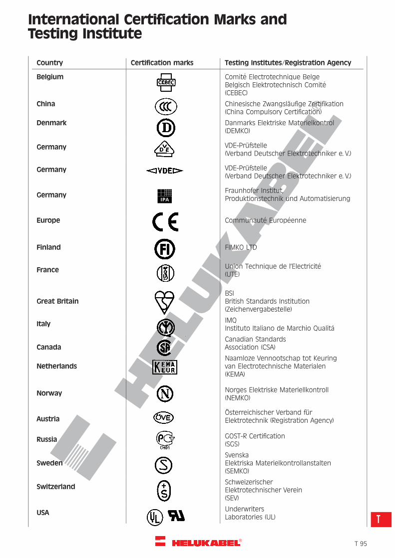
R
International Certification Marks andTesting Institute
Country Certification marks Testing Institutes/Registration Agency
Belgium Comite Electrotechnique BelgeBelgisch Elektrotechnisch Comite(CEBEC)
China Chinesische Zwangslaufige Zertifikation(China Compulsory Certification)
Denmark Danmarks Elektriske Materielkontrol(DEMKO)
Germany VDE-Prufstelle(Verband Deutscher Elektrotechniker e. V.)
Germany VDE-Prufstelle(Verband Deutscher Elektrotechniker e. V.)
GermanyFraunhofer Institut,Produktionstechnik und Automatisierung
Europe Communaute Europeenne
Finland FIMKO LTD
France Union Technique de l’Electricite(UTE)
Great BritainBSIBritish Standards Institution(Zeichenvergabestelle)
Italy IMQInstituto Italiano de Marchio Qualita
CanadaCanadian StandardsAssociation (CSA)
NetherlandsNaamloze Vennootschap tot Keuringvan Electrotechnische Materialen(KEMA)
Norway Norges Elektriske Materiellkontroll(NEMKO)
AustriaOsterreichischer Verband furElektrotechnik (Registration Agency)
Russia GOST-R Certification(SGS)
SwedenSvenskaElektriska Materielkontrollanstalten(SEMKO)
SwitzerlandSchweizerischerElektrotechnischer Verein(SEV)
USA UnderwritersLaboratories (UL)
�T 95
T
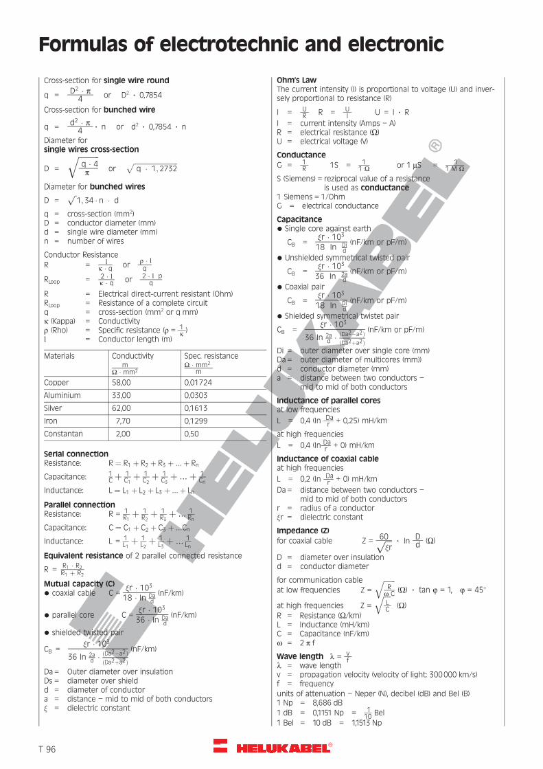
R
Formulas of electrotechnic and electronic
Cross-section for single wire round
q = D2 � p4 or D2 ? 0,7854
Cross-section for bunched wire
q = d2 � p4 ? n or d2 ? 0,7854 ? n
Diameter forsingle wires cross-section
D =
ffiffiffiffiffiffiffiffiffi
q � 4p
q
orffiffiffiffiffiffiffiffiffiffiffiffiffiffiffiffiffiffiffiffiffiffiffiffiffiffiffi
q � 1; 2732p
Diameter for bunched wires
D =ffip1; 34 � n � d
q = cross-section (mm2)D = conductor diameter (mm)d = single wire diameter (mm)n = number of wires
Conductor ResistanceR = l
k � q orr � lq
RLoop = 2 � lk � q or 2 � l p
q
R = Electrical direct-current resistant (Ohm)RLoop = Resistance of a complete circuitq = cross-section (mm2 or q mm)k (Kappa) = Conductivityr (Rho) = Specific resistance (r = 1
k )l = Conductor length (m)
Materials Conductivitym
W � mm2
Spec. resistanceW � mm2
m
Copper 58,00 0,01724
Aluminium 33,00 0,0303
Silver 62,00 0,1613
Iron 7,70 0,1299
Constantan 2,00 0,50
Serial connectionResistance: R ¼ R1 þ R2 þ R3 þ :::þ Rn
Capacitance: 1C þ 1
C1þ 1
C2þ 1
C3þ :::þ 1
Cn
Inductance: L ¼ L1 þ L2 þ L3 þ :::þ Ln
Parallel connectionResistance: R = 1
R1þ 1
R2þ 1
R3þ ::: 1
Rn
Capacitance: C ¼ C1 þ C2 þ C3 þ :::Cn
Inductance: L = 1L1þ 1
L2þ 1
L3þ ::: 1
Ln
Equivalent resistance of 2 parallel connected resistance
R = R1 � R2R1 þ R2
Mutual capacity (C)* coaxial cable C =
�r � 10318 � In Da
d
(nF/km)
* parallel core C =�r � 10336 � In Da
d
(nF/km)
* shielded twisted pair
CB =�r � 103
36 In 2ad � ðDa2�a2Þ
ðDa2þa2Þ
(nF/km)
Da= Outer diameter over insulationDs = diameter over shieldd = diameter of conductora = distance – mid to mid of both conductors� = dielectric constant
Ohm’s LawThe current intensity (I) is proportional to voltage (U) and inver-sely proportional to resistance (R)
I = UR R = U
I U = I ? R
I = current intensity (Amps – A)R = electrical resistance (W)U = electrical voltage (V)
ConductanceG = 1
R 1S = 11 W or 1 mS = 1
1 M WS (Siemens) = reziprocal value of a resistance
is used as conductance1 Siemens = 1/OhmG = electrical conductance
Capacitance* Single core against earth
CB =�r � 10318 In Di
d
(nF/km or pF/m)
* Unshielded symmetrical twisted pair
CB =�r � 10336 In 2a
d
(nF/km or pF/m)
* Coaxial pair
CB =�r � 10318 In Di
d
(nF/km or pF/m)
* Shielded symmetrical twistet pair
CB =�r � 103
36 In 2ad � ðDa2�a2Þ
ðDa2þa2Þ
(nF/km or pF/m)
Di = outer diameter over single core (mm)Da= outer diameter of multicores (mm))d = conductor diameter (mm)a = distance between two conductors –
mid to mid of both conductors
Inductance of parallel coresat low frequencies
L = 0,4 (In Dar + 0,25) mH/km
at high frequencies
L = 0,4 (In Dar + 0) mH/km
Inductance of coaxial cableat high frequencies
L = 0,2 (In Dar + 0) mH/km
Da= distance between two conductors –mid to mid of both conductors
r = radius of a conductor�r = dielectric constant
Impedance (Z)for coaxial cable Z = 60
ffiffiffi
�rp ? In
Dd (W)
D = diameter over insulationd = conductor diameter
for communication cableat low frequencies Z =
ffiffiffiffiffiffi
Rw C
q
(W) ? tan j = 1, j = 458
at high frequencies Z =
ffiffiffiffi
LC
q
(W)R = Resistance (W/km)L = Inductance (mH/km)C = Capacitance (nF/km)w = 2 p f
Wave length l = vf
l = wave lengthv = propagation velocity (velocity of light: 300000 km/s)f = frequencyunits of attenuation – Neper (N), decibel (dB) and Bel (B)1 Np = 8,686 dB1 dB = 0,1151 Np = 1
10 Bel1 Bel = 10 dB = 1,1513 Np
�T 96
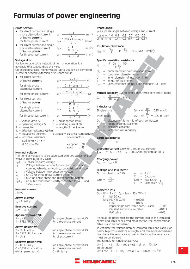
R
Formulas of power engineering
Cross section* for direct current and single
phase alternative current q = 2 � I � lk � u (mm2)
of known currentfor three-phase current q =
1;732 � I � cosj � lk � u (mm2)
* for direct current and singlephase alternative current q = 2 � I � P
k � u � U (mm2)of known powerfor three-phase current q = I � P
k � u � U (mm2)
Voltage dropFor low voltage cable network of normal operation, it isadvisable of a voltage drop of 3–5%.On exceptional case, higher values (up to 7%) can be permittedin case of network-extension or in short-circuit.* for direct current
of known current u = 2 � I � lk � q (V)
for single phasealternative current u =
2 � I � cosj � lk � q (V)
for three-phase current u =1;732 � I � cosj � l
k � q (V)
* for direct current
of known power u = 2 � I � Pk � q � U (V)
for single phasealternative current u = 2 � I � P
k � q � U (V)
for three-phase current u = I � Pk � q � U (V)
u = voltage drop (V) q = cross-section (mm2)U = operating voltage (V) I = working current (A)P = power (W) l = length of the line (m)Rw = effective resistance (W/km)L = Inductance (mH/km) k (Kappa) = electrical conductivitywL = inductive resistance of conductors
(W)/km) (w = 2 ? p ? fat 50 Hz = 314) k-copper : 58
k-Alu : 33
Nominal voltageThe nominal voltage is to be expressed with two values of alter-native current U0/U in V (Volt).U0/U = phase-to-earth voltageU0 : Voltage between conductor and earth or metallic
covering (shields, armouring, concentric conductor)U : Voltage between two outer conductorsU0 : U/
ffiffiffi
3p
for three-phase current systemsU0 : U/2 for single-phase and direct current systemsU0/U0 : an outer conductor is earth-connected for A.C.- and
D.C.-systems
Nominal currentI in (A)
Active currentIw = I ? cos j
Reactive currentI0 = I ? sin j
Apparent power (VA)S = U ? I for single phase current (A.C.)S = 1,732 ? U ? I for three-phase current
Active power (W)P = U ? I ? cos j for single phase current (A.C.)P = 1,732 ? U ? I ? cos j for three-phase currentP = U ? I for direct current
Reactive power (var)Q = U ? I ? sin j for single phase current (A.C.)Q = 1,732 ? U ? I ? sin j for three-phase current(Voltampere reactiv) Q = P ? tan j
Phase anglej is a phase angle between voltage and current
cos j ¼ 1;0 0;9 0;8 0;7 0;6 0;5sin j ¼ 0 0;44 0;6 0;71 0;8 0;87
Insulation resistance
Riso =Sisol
? InDad ? 10–8 (MW ? km)
Specific Insulation resistance
Rs = R � 2� � l � 108
In Dadi
Da = outer diameter over insulation (mm)d = conductor diameter (mm)di = inner diameter of insulation (mm)l = length of the line (m)Siso = Spec. resistance of insulation materials (W ? cm)
Mutual capacity (CB) for single-core, three-core and H-cable)
CB =�r � 10318 In Da
d
(nF/km)
Inductance
Single-phase 0,4 ? (InDar + 0,25) mH/km
three-phase 0,2 ? (InDar + 0,25) mH/km
Da = distance – mid to mid of both conductorsr = radius of conductor (mm)�r = dielectric constant0,25 = factor for low frequency
Earth capacitanceEC = 0,6 ? CB
Charging current (only for three-phase current)ILad = U ? 2 p f ? CB ? 10–6 A/km per core at 50 Hz
Charging powerPLad = ILad ? U
Leakage and loss factorG = tand ? w C (S) w = 2 p f
C = Capacitytand = G
w C tand = loss factorS = Siemens =
11W
Dielectric lossDv = U2 ? 2 p f ? CB ? tan ? 10–6 (W/km)
f bei 50 Hztand PE/VPE (XLPE) ,0,0005
EPR ,0,005Paper-single core, three-core, H-cable ,0,003Oil-filled and pressure cable ,0,003PVC cable ,0,05
It should be noted that for the current load of the insulatedcables and wires of selected cross-section, the power ratingstable is also be considered.
To estimate the voltage drop of insulated wires and cables forheavy (big) cross-sections of single- and three-phase-overheadline, the active resistance as well as the inductive resistancemust be considered.The formula for single-phase (A.C.):
U = 2 ? l ? I ? (Rw ? cos j + wL ? sin j) ? 10–3 (V)Three-phase:U = 1,732 ? l ? I ? (Rw ? cos j + wL ? sin j) ? 10–3 (V)
�T 97
T
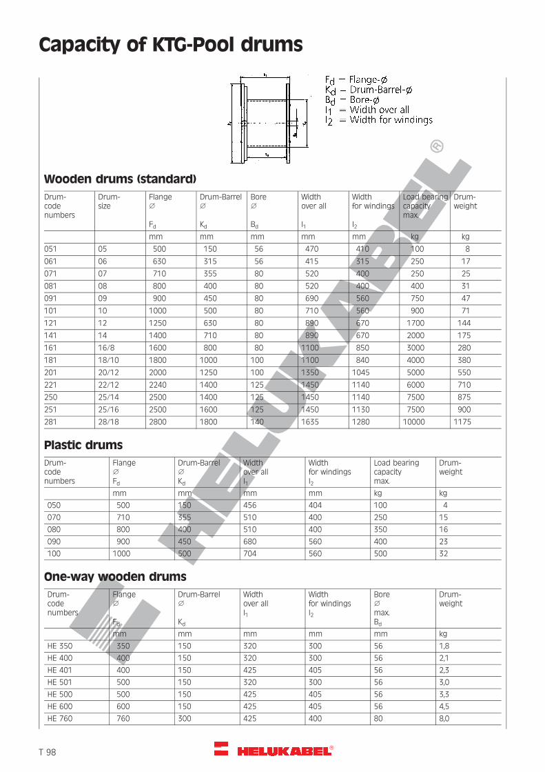
R
Capacity of KTG-Pool drums
Wooden drums (standard)
Drum-codenumbers
Drum-size
Flange1
Fd
Drum-Barrel1
Kd
Bore1
Bd
Widthover all
I1
Widthfor windings
I2
Load bearingcapacitymax.
Drum-weight
mm mm mm mm mm kg kg
051 05 500 150 56 470 410 100 8
061 06 630 315 56 415 315 250 17
071 07 710 355 80 520 400 250 25
081 08 800 400 80 520 400 400 31
091 09 900 450 80 690 560 750 47
101 10 1000 500 80 710 560 900 71
121 12 1250 630 80 890 670 1700 144
141 14 1400 710 80 890 670 2000 175
161 16/8 1600 800 80 1100 850 3000 280
181 18/10 1800 1000 100 1100 840 4000 380
201 20/12 2000 1250 100 1350 1045 5000 550
221 22/12 2240 1400 125 1450 1140 6000 710
250 25/14 2500 1400 125 1450 1140 7500 875
251 25/16 2500 1600 125 1450 1130 7500 900
281 28/18 2800 1800 140 1635 1280 10000 1175
Plastic drums
Drum-codenumbers
Flange1
Fd
Drum-Barrel1
Kd
Widthover allI1
Widthfor windingsI2
Load bearingcapacitymax.
Drum-weight
mm mm mm mm kg kg
050 500 150 456 404 100 4
070 710 355 510 400 250 15
080 800 400 510 400 350 16
090 900 450 680 560 400 23
100 1000 500 704 560 500 32
One-way wooden drums
Drum-codenumbers
Flange1
Fd
Drum-Barrel1
Kd
Widthover allI1
Widthfor windingsI2
Bore1
max.Bd
Drum-weight
mm mm mm mm mm kg
HE 350 350 150 320 300 56 1,8
HE 400 400 150 320 300 56 2,1
HE 401 400 150 425 405 56 2,3
HE 501 500 150 320 300 56 3,0
HE 500 500 150 425 405 56 3,3
HE 600 600 150 425 405 56 4,5
HE 760 760 300 425 400 80 8,0
�T 98
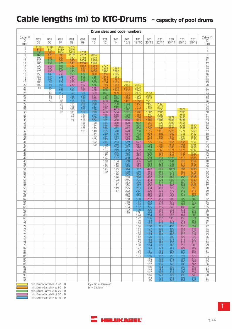
R
Cable lengths (m) to KTG-Drums – capacity of pool drums
Drum sizes and code numbers
Cable 1
Dmm
05105
06106
07107
08108
09109
10110
12112
14114
16116/8
18118/10
20120/12
22122/14
25025/14
25125/16
28128/18
Cable 1
Dmm
6 1130 1110 2024 2755 67 815 840 1480 2340 78 630 640 1064 1463 2730 89 460 470 890 1152 2202 2866 910 390 388 680 980 1768 2349 1011 320 315 564 760 1404 1910 1112 260 254 470 643 1206 1540 1213 220 238 385 542 1032 1339 2727 1314 190 190 360 454 880 1159 2265 2967 1415 170 180 300 430 749 1000 1990 2480 1516 150 140 239 358 632 860 1756 2205 1617 130 134 228 294 603 736 1545 1960 1718 110 102 218 280 505 705 1355 1737 1819 105 96 172 228 485 599 1184 1535 2722 1920 100 92 165 220 402 576 1139 1352 2435 2830 2021 80 90 159 210 387 485 990 1304 2172 2527 2122 65 122 167 315 468 856 1145 1930 2248 2223 62 117 160 304 389 827 999 1870 2172 2954 2324 60 113 156 294 377 709 967 1657 1927 2608 2425 58 110 150 285 365 688 839 1608 1867 2522 2526 56 80 116 226 299 668 814 1420 1650 2218 2627 78 113 220 290 567 700 1244 1450 2150 2860 2728 76 109 215 282 550 680 1210 1410 1880 2777 2829 73 106 209 226 462 663 1180 1370 1826 2450 2976 2930 70 103 162 220 450 564 1028 1200 1583 2383 2893 3031 76 157 214 438 550 1003 1166 1540 2089 2558 3132 74 153 209 428 537 866 1009 1500 2035 2978 2490 3233 72 150 204 352 450 846 985 1289 1984 2908 2428 3334 146 158 344 440 828 962 1257 1726 2605 2134 3435 108 154 336 430 710 824 1227 1685 2547 2083 2890 3536 105 150 329 422 692 806 1040 1646 2270 2035 2820 3637 103 148 265 348 678 788 1017 1418 2223 1774 2760 3738 144 259 340 664 772 994 1386 1969 1735 2432 3839 110 254 334 560 653 972 1356 1930 1697 2380 3940 105 249 327 549 640 812 1328 1892 1486 2330 4041 102 244 264 539 627 795 1130 1664 1435 2036 4142 100 190 259 529 615 779 1107 1633 1406 1995 4243 187 254 437 510 763 1085 1603 1199 1956 4344 183 249 430 502 750 1065 1574 1175 1692 4445 180 245 422 492 610 890 1373 1153 1660 4546 177 240 415 484 600 874 1349 1130 1630 4647 174 187 408 475 589 858 1326 1110 1600 4748 130 184 330 386 578 842 1144 930 1366 4849 127 180 325 380 568 828 1125 914 1342 4950 125 178 319 373 558 878 1107 898 1320 5051 123 175 314 367 442 666 1089 883 1298 5152 120 172 310 360 435 655 1072 869 1276 5253 170 305 356 428 644 912 715 1072 5354 126 230 280 420 634 898 700 1056 5455 124 235 276 414 624 885 690 1040 5556 122 232 270 408 614 872 680 1022 5657 121 228 267 400 488 860 668 1006 5758 119 225 263 304 480 720 658 990 5859 117 222 260 300 473 710 649 815 5960 220 256 295 466 700 640 803 6061 216 252 290 460 690 610 790 6162 160 190 287 453 680 500 780 6263 158 187 282 448 670 494 770 6364 156 184 280 440 662 487 760 6465 154 182 275 335 640 480 748 6566 152 180 270 330 534 474 738 6667 150 178 266 326 528 468 588 6768 174 264 320 520 462 580 6869 172 186 317 515 456 574 6970 170 184 313 510 450 566 7071 168 182 310 502 342 558 7172 166 180 305 498 338 552 7273 164 177 300 490 334 545 7374 162 175 297 486 330 540 7475 160 173 294 480 326 532 7576 112 170 291 380 322 526 7677 110 168 287 375 318 520 7778 109 166 284 370 314 514 7879 108 164 281 367 310 508 7980 107 163 278 363 306 502 8081 106 161 196 360 304 382 8182 105 158 194 356 300 378 8283 103 156 192 352 297 375 8384 155 190 349 294 370 8485 154 188 345 290 367 8586 152 186 342 288 363 8687 150 184 338 285 359 8788 149 182 335 202 355 8889 147 180 332 200 352 8990 146 178 329 198 348 9091 144 176 248 196 345 9192 90 175 245 194 340 92
min. Drum-Barrel-1 % 40 ? D Kd = Drum-Barrel-1
min. Drum-Barrel-1 % 30 ? D D = Cable-1
min. Drum-Barrel-1 % 25 ? Dmin. Drum-Barrel-1 % 20 ? Dmin. Drum-Barrel-1 % 15 ? D
�T 99
T
R
Explanatory notes on CE markingLow Voltage Directive (NSR), EMC Legislation
The Manufacturers must have to identify thoseproducts by the CE marking which fall within theapplicability of certain EC (European Community)directives.
This applies to products which are covered by thesedirectives in accordance with the new concept toinclude particular requirements on the technicalcharacteristics of products.
The realization of these requirements is the condi-tion for marketing the products in Europe. Thenthese CE directives constitute binding legislation forthe European Union.
The inclusion of the CE marking confirms thecompliance by the products with the basic require-ments of all specifications applicable to thatproduct. This means that CE marking is thus thecompelling requirement in order of placing theproducts on the market within the EU. This alsoapplies in the country of manufacture.
These directives are only then binding when thesehave been implemented in the national legislationof individual EU member states. An implementationin the national legislation of individual membersstates does not always occurs at the same time andis not always accomplished within the foreseenperiod.Furthermore, certain transition rules may apply. Ifthe obligation for implementation of these directivesis not met, then these directives can still be directlyapplicable in certain circumstances.
The validity for these directives are not alwaysclearly formulated and are sometimes abstract andnot differentiated such that it cannot always beunambiguously established whether a product iscovered by one or more directives and thus requiresthe CE marking.
The CE marking serves as evidence to the supervi-sory authorities of compliance with these directives.It is however often misinterpreted as being a“symbol for safety or quality” which is why it is oftenrequested from customers without any legal justifi-cation.
EC Low Voltage Directive (NSR)
The EC Low Voltage Directive (NSR) is one of theseCE Designation Directives (Article 13 of the CEMarking Directive). This means that electrical equip-ment used in low voltage range applications mustalso be identified by the CE marking. The CEmarking is affixed on these products since01.01.1997.
The CE Marking Directive will apply to a largenumber of electrical products, alone on account ofthe extensive range of applicability of the LowVoltage (NSR) and Electromagnetic Compatibility(EMC) Directives.
The following directives are of particularsignificance for the electrical industry:
73/23/EEC and 93/68/EECElectrical equipment for use within specifiedvoltage limits (Low Voltage Directive)
89/106/EECConstruction products
89/336/EECElectromagnetic compatibility (EMC Directive)
89/392/EECSafety of machinery
91/263/EECTelecommunications terminal equipment
For HELUKABEL as manufacturer and supplier ofcables and wires, only the Low Voltage Directive is ofsignificance. The EMC directive is of indirect applic-ability – for customer enquiries – in that queriescould arise regarding the immunity of cables tointerference, capacitance unbalance values andsimilar characteristics.
The EMC Directive
The EMC Directive, which applies for the electro-magnetic compatibility of electrical and electronicequipment in their environments, can only beapplied in complete systems.
For example, systems which are made up of severalunits, whereby each individual unit alone meet EMCrequirements, are tested as a system for EMCtogether with the interconnecting cables.
EMC testing of a single cable or a single wire cannotbe specified.
Title:73/23/EEC and 93/68/EEC: Directive of the Councildated February 19, 1973, for harmonisation of thelegislation in member states regarding electricalequipment for use within specified voltage ranges –with amendments dated July 22, 1993.
Continuation "
�T 100
R
Explanatory notes on CE markingLow Voltage Directive (NSR), EMC Legislation
Important information regarding the LowVoltage Directive (NSR):
1. General Conditions:
a) The major characteristics required for know-ledge and observance, for use in accordancewith the intended application, are given on theelectrical equipment, or, if this is not possible,in the accompanying instructions.
b) The manufacturer’s symbol or trade mark shallbe clearly visible on the electrical equipment,or, where this is not possible, shall be affixedon the packaging.
c) The electrical devices as well as the compo-nents for these, shall be procured such thatthese can be connected safely and properly.
d) The electrical equipment shall be designedand constructed such that protection from thehazards listed in item 2 and 3, is assuredduring use and proper maintenance in accor-dance with the intended application.
2. Protection against hazards which may arisefrom electrical equipment – technicalmeasures shall be foreseen in accordancewith item 1, such that:
a) Humans and working animals are protectedfrom injury or other harm which can be causedby either direct or indirect contact.
b) No high temperatures, arcs or radiation aregenerated from which hazards could arise.
c) Humans, working animals and property areadequately protected against non-electricalhazards which, from experience, can arise fromelectrical equipment.
d) The insulation complies to the property re-quirements.
3. Protection against hazards which can arisefrom external influences on electrical equip-ment – technical measures are foreseen inaccordance with item 1, such that the elec-trical equipment:
a) can withstand the mechanical loads such thathumans, working animals or property are notendangered.
b) can withstand the non-mechanical effectsunder foreseen environmental conditions suchthat humans, working animals or property arenot endangered.
c) cannot endanger humans, working animals orproperty in any way by the foreseen overloads.
Equipment and areas which do not fall within theDirective.
* Electrical equipment for use in explosiveatmospheres
* Electrical-radiological and electrical medicalequipment
* Electrical components of passenger and goodslifts
* Electricity meters, household plug-in fixtures,radio interference suppression devices
* Installation for supplying power to electrifiedpasture fencing
* Specified electrical equipment intended for useon ships, in aircraft or railways and which complywith the safety regulations of member states forinternational installations.
Electrical equipment within the context of the LowVoltage Directive is electrical equipment for applica-tions with a rated voltage between 50 and 1000 Valternating current and between 75 and 1500 Vdirect current.
For a more exact interpretation of the Directive,cables and wires are covered by the regulation, nothowever cables with a rated voltage exceeding1000 V alternating current or 1500 V direct current.
HELUKABEL as manufacturer and supplier must actin accordance with the Low Voltage Directive, that isto say:
Cables and wires up to 1000 V nominal voltagemust be identified by the CE marking, refer topage T 95.
The identification can be attached either to theproduct or on the label.
�T 101
T

R
Part Number Index
Part No. Page Part No. Page Part No. Page
"
From Part No.10001 – 15713
10001 — 10059 A 1
10060 — 10168 A 2
10169 A 1
10170 A 2
10172 — 10173 A 1
10174 — 10176 A 2
10177 — 10178 A 1
10179 — 10181 A 2
10182 — 10183 A 1
10184 — 10199 A 2
10200 — 10272 A 10
10273 — 10331 A 11
10332 A 10
10333 A 2
10334 — 10339 A 17
10400 — 10473 A 12
10474 — 10532 A 13
10533 — 10534 A 1
10535 — 10536 A 2
10537 — 10547 A 16
10550 — 10615 A 5
10616 — 10746 A 6
10747 — 10749 A 16
10800 — 10880 A 9
10881 — 10904 A 3
10910 — 10933 A 4
11001 — 11097 A 14
11104 — 11160 A 15
11201 — 11240 G 29
11241 — 11331 G 30
11464 — 11584 A 7
11590 — 11629 A 8
11656 — 11733 G 31
11744 — 11812 G 32
11815 — 11941 A 77
12001 — 12056 A 18
12057 — 12111 A 19
12112 — 12114 A 18
12115 — 12119 A 19
12188 A 18
12200 — 12301 A 20
12302 — 12311 A 21
12312 — 12313 A 20
12314 — 12317 A 21
12318 — 12319 A 20
12320 — 12326 A 21
12327 A 19
12328 A 21
12345 — 12470 A 78
12471 — 12527 A 24
12528 — 12543 A 25
12550 — 12620 A 28
12630 — 12671 A 32
12680 — 12722 A 34
13001 — 13036 B 1
13037 — 13059 B 2
13060 — 13095 B 4
13096 — 13118 B 5
13119 B 1
13120 — 13121 B 2
13122 — 13127 B 1
13128 B 2
13129 — 13131 B 4
13132 B 5
13133 — 13136 B 3
13137 A 8
13138 B 3
13139 — 13140 A 2
13141 — 13146 B 3
13147 A 8
13148 — 13160 B 3
13170 — 13197 B 6
13920 — 13936 B 1
13937 — 13949 B 2
13951 — 13970 B 4
13971 — 13985 B 5
14001 — 14076 A 104
14077 — 14087 A 105
14088 A 104
14089 — 14092 A 105
14093 — 14099 A 105
14100 — 14102 A 104
15001 — 15054 A 40
15055 — 15089 A 41
15090 — 15092 A 40
15093 — 15141 D 10
15142 — 15150 A 41
15151 — 15163 A 42
15100 — 15113 D 10
15200 — 15213 D 10
15214 A 40
15215 — 15216 A 41
15300 — 15313 D 10
15400 — 15413 D 10
15500 — 15513 D 10
15520 — 15573 A 46
15575 — 15592 A 47
15600 — 15613 D 10
15620 — 15652 A 47
15700 — 15713 D 10
�T 102
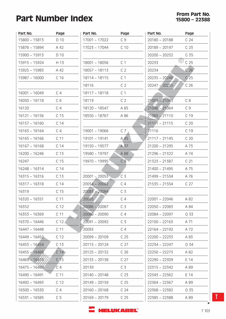
R
15800 — 15813 D 10
15876 — 15894 A 42
15900 — 15913 D 10
15915 — 15924 H 13
15925 — 15983 A 42
15987 — 16000 C 16
16001 — 16049 C 4
16050 — 16118 C 6
16120 C 4
16121 — 16156 C 15
16157 — 16160 C 14
16163 — 16164 C 4
16165 — 16166 C 11
16167 — 16168 C 14
16200 — 16246 C 13
16247 C 15
16248 — 16314 C 14
16315 — 16316 C 13
16317 — 16318 C 14
16319 C 15
16320 — 16351 C 11
16352 C 12
16353 — 16369 C 11
16370 — 16446 C 12
16447 — 16448 C 11
16449 — 16452 C 12
16453 — 16454 C 13
16455 — 16468 C 14
16469 — 16474 C 15
16475 — 16489 C 4
16490 — 16491 C 11
16492 — 16493 C 12
16500 — 16530 C 4
16531 — 16585 C 5
17001 — 17022 C 9
17023 — 17044 C 10
18001 — 18056 C 1
18057 — 18113 C 2
18114 — 18115 C 1
18116 C 2
18117 — 18118 C 1
18119 C 2
18120 — 18547 A 85
18550 — 18767 A 86
19001 — 19066 C 7
19101 — 19141 A 45
19150 — 19577 A 87
19580 — 19797 A 88
19970 — 19995 C 9
20001 — 20053 C 3
20054 — 20082 C 4
20083 — 20084 C 3
20085 C 4
20086 — 20087 C 3
20088 — 20090 C 4
20091 — 20092 C 3
20093 C 4
20099 — 20109 C 25
20115 — 20124 C 27
20125 — 20132 C 26
20133 — 20138 C 27
20139 C 3
20140 — 20148 C 23
20149 — 20159 C 25
20160 — 20168 C 24
20169 — 20179 C 25
20180 — 20188 C 24
20189 — 20197 C 23
20200 — 20232 G 35
20233 C 25
20234 C 26
20235 — 20246 C 25
20247 — 20255 C 26
21001 — 21045 C 8
21046 — 21064 C 9
21065 — 21110 C 19
21111 — 21115 C 20
21116 C 19
21117 — 21145 C 20
21200 — 21295 A 73
21296 — 21322 A 74
21323 — 21387 C 21
21400 — 21495 A 75
21499 — 21534 A 76
21535 — 21554 C 27
22001 — 22046 A 82
22050 — 22083 A 84
22084 — 22097 Q 33
22100 — 22163 A 71
22164 — 22192 A 72
22200 — 22233 A 83
22234 — 22247 Q 34
22250 — 22273 A 82
22290 — 22309 E 14
22315 — 22342 A 89
22343 — 22362 E 14
22364 — 22367 A 89
22368 — 22382 Q 35
22385 — 22388 A 89
Part No. Page Part No. Page Part No. Page
Part Number Index
"
From Part No.15800 – 22388
�T 103
T

R
Part Number Index
22400 — 22451 A 48
22452 — 22494 A 49
22495 — 22499 E 32
22501 — 22565 A 50
22571 — 22592 A 51
22593 — 22634 A 52
22637 — 22667 E 7
22673 — 22687 Q 36
22800 Q 45
22801 Q 41
22802 — 22806 Q 45
22810 — 22814 Q 42
22818 Q 40
22819 Q 42
22820 Q 43
22823 Q 40
22824 — 22825 Q 39
22827 Q 41
22834 Q 44
22845 — 22846 Q 43
22847 Q 46
22848 — 22849 Q 44
22850 — 22853 Q 46
22854 — 22869 Q 37
22870 — 22877 A 68
22878 — 22883 A 50
22884 — 22889 A 52
22890 — 22892 Q 41
22960 — 22967 Q 37
22970 — 22985 A 68
22989 — 23012 E 1
23013 — 23059 E 2
23062 — 23103 E 3
23104 — 23105 E 1
23106 — 23110 E 9
23111 — 23126 E 11
23127 — 23136 E 1
23137 — 23146 E 2
23147 — 23149 E 9
23151 — 23199 E 4
23200 — 23913 E 8
23214 — 23252 E 5
23253 — 23290 E 6
23314 — 23388 A 70
23914 — 23949 A 67
23953 — 23959 E 8
23960 — 23987 E 13
24002 — 24046 E 17
24050 — 24085 A 56
24086 — 24118 A 62
24119 — 24155 A 58
24156 — 24190 A 64
24191 — 24235 A 60
24236 — 24272 A 66
24273 — 24285 E 15
24291 — 24292 E 17
24295 — 24330 A 57
24335 — 24367 A 63
24370 — 24406 A 59
24410 — 24444 A 65
24450 — 24488 A 61
24501 — 24566 E 15
24567 — 24582 A 53
24600 — 24813 E 8
24614 — 24629 A 54
25001 — 25075 O 2
25080 — 25101 O 5
25259 — 25268 O 4
25269 — 25294 A 55
25439 Q 31
25440 Q 31
25459 — 25462 Q 31
25508 Q 31
25511 — 25618 E 15
25620 — 25690 A 92
25691 — 25760 A 93
25761 — 25825 A 94
25826 — 25887 A 95
26001 — 26032 O 7
26035 — 26059 O 6
26060 — 26069 D 5
26070 — 26091 O 1
26092 D 5
26093 — 26098 Q 32
26099 D 5
26100 — 26107 O 3
26108 — 26119 D 5
26120 — 26124 Q 32
26125 — 26215 A 96
26217 — 26265 A 97
26266 — 26306 A 98
26307 — 26346 A 100
26347 — 26385 A 101
26405 — 26500 D 1
26505 — 26584 D 2
26590 — 26687 D 3
26690 — 26753 D 4
26755 — 26936 D 5
26937 — 26960 D 6
26980 — 27029 J 1
Part No. Page Part No. Page Part No. Page
From Part No.22400 – 27029
"
�T 104
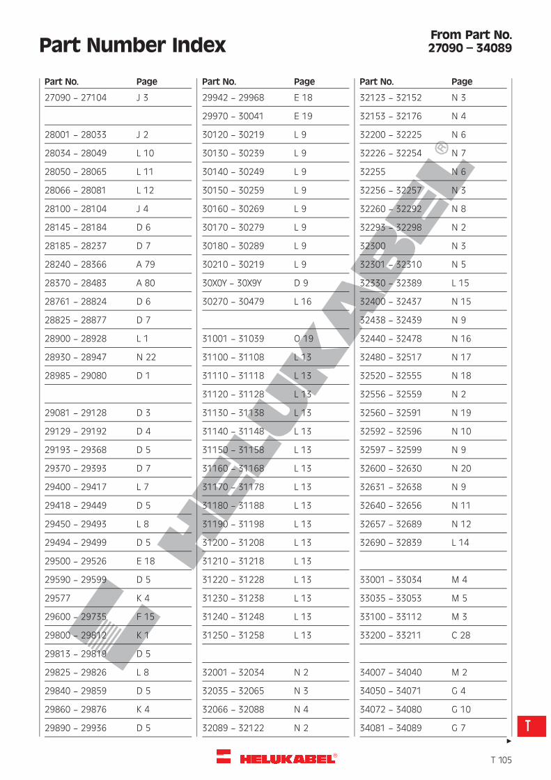
R
Part Number Index
27090 — 27104 J 3
28001 — 28033 J 2
28034 — 28049 L 10
28050 — 28065 L 11
28066 — 28081 L 12
28100 — 28104 J 4
28145 — 28184 D 6
28185 — 28237 D 7
28240 — 28366 A 79
28370 — 28483 A 80
28761 — 28824 D 6
28825 — 28877 D 7
28900 — 28928 L 1
28930 — 28947 N 22
28985 — 29080 D 1
29081 — 29128 D 3
29129 — 29192 D 4
29193 — 29368 D 5
29370 — 29393 D 7
29400 — 29417 L 7
29418 — 29449 D 5
29450 — 29493 L 8
29494 — 29499 D 5
29500 — 29526 E 18
29590 — 29599 D 5
29577 K 4
29600 — 29735 F 15
29800 — 29812 K 1
29813 — 29819 D 5
29825 — 29826 L 8
29840 — 29859 D 5
29860 — 29876 K 4
29890 — 29936 D 5
29942 — 29968 E 18
29970 — 30041 E 19
30120 — 30219 L 9
30130 — 30239 L 9
30140 — 30249 L 9
30150 — 30259 L 9
30160 — 30269 L 9
30170 — 30279 L 9
30180 — 30289 L 9
30210 — 30219 L 9
30X0Y — 30X9Y D 9
30270 — 30479 L 16
31001 — 31039 O 19
31100 — 31108 L 13
31110 — 31118 L 13
31120 — 31128 L 13
31130 — 31138 L 13
31140 — 31148 L 13
31150 — 31158 L 13
31160 — 31168 L 13
31170 — 31178 L 13
31180 — 31188 L 13
31190 — 31198 L 13
31200 — 31208 L 13
31210 — 31218 L 13
31220 — 31228 L 13
31230 — 31238 L 13
31240 — 31248 L 13
31250 — 31258 L 13
32001 — 32034 N 2
32035 — 32065 N 3
32066 — 32088 N 4
32089 — 32122 N 2
32123 — 32152 N 3
32153 — 32176 N 4
32200 — 32225 N 6
32226 — 32254 N 7
32255 N 6
32256 — 32257 N 3
32260 — 32292 N 8
32293 — 32298 N 2
32300 N 3
32301 — 32310 N 5
32330 — 32389 L 15
32400 — 32437 N 15
32438 — 32439 N 9
32440 — 32478 N 16
32480 — 32517 N 17
32520 — 32555 N 18
32556 — 32559 N 2
32560 — 32591 N 19
32592 — 32596 N 10
32597 — 32599 N 9
32600 — 32630 N 20
32631 — 32638 N 9
32640 — 32656 N 11
32657 — 32689 N 12
32690 — 32839 L 14
33001 — 33034 M 4
33035 — 33053 M 5
33100 — 33112 M 3
33200 — 33211 C 28
34007 — 34040 M 2
34050 — 34071 G 4
34072 — 34080 G 10
34081 — 34089 G 7
Part No. Page Part No. Page Part No. Page
From Part No.27090 – 34089
"
�T 105
T
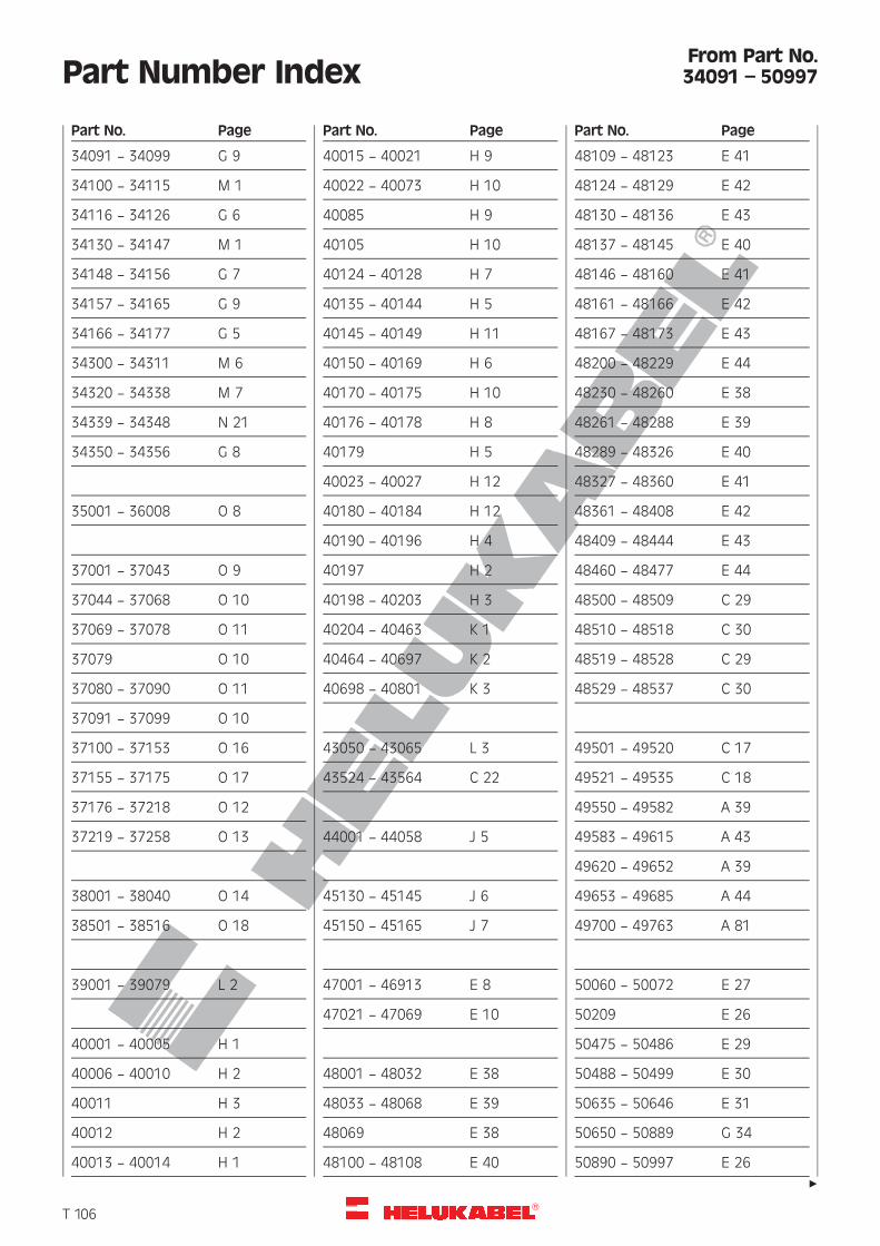
R
Part Number Index
34091 — 34099 G 9
34100 — 34115 M 1
34116 — 34126 G 6
34130 — 34147 M 1
34148 — 34156 G 7
34157 — 34165 G 9
34166 — 34177 G 5
34300 — 34311 M 6
34320 — 34338 M 7
34339 — 34348 N 21
34350 — 34356 G 8
35001 — 36008 O 8
37001 — 37043 O 9
37044 — 37068 O 10
37069 — 37078 O 11
37079 O 10
37080 — 37090 O 11
37091 — 37099 O 10
37100 — 37153 O 16
37155 — 37175 O 17
37176 — 37218 O 12
37219 — 37258 O 13
38001 — 38040 O 14
38501 — 38516 O 18
39001 — 39079 L 2
40001 — 40005 H 1
40006 — 40010 H 2
40011 H 3
40012 H 2
40013 — 40014 H 1
40015 — 40021 H 9
40022 — 40073 H 10
40085 H 9
40105 H 10
40124 — 40128 H 7
40135 — 40144 H 5
40145 — 40149 H 11
40150 — 40169 H 6
40170 — 40175 H 10
40176 — 40178 H 8
40179 H 5
40023 — 40027 H 12
40180 — 40184 H 12
40190 — 40196 H 4
40197 H 2
40198 — 40203 H 3
40204 — 40463 K 1
40464 — 40697 K 2
40698 — 40801 K 3
43050 — 43065 L 3
43524 — 43564 C 22
44001 — 44058 J 5
45130 — 45145 J 6
45150 — 45165 J 7
47001 — 46913 E 8
47021 — 47069 E 10
48001 — 48032 E 38
48033 — 48068 E 39
48069 E 38
48100 — 48108 E 40
48109 — 48123 E 41
48124 — 48129 E 42
48130 — 48136 E 43
48137 — 48145 E 40
48146 — 48160 E 41
48161 — 48166 E 42
48167 — 48173 E 43
48200 — 48229 E 44
48230 — 48260 E 38
48261 — 48288 E 39
48289 — 48326 E 40
48327 — 48360 E 41
48361 — 48408 E 42
48409 — 48444 E 43
48460 — 48477 E 44
48500 — 48509 C 29
48510 — 48518 C 30
48519 — 48528 C 29
48529 — 48537 C 30
49501 — 49520 C 17
49521 — 49535 C 18
49550 — 49582 A 39
49583 — 49615 A 43
49620 — 49652 A 39
49653 — 49685 A 44
49700 — 49763 A 81
50060 — 50072 E 27
50209 E 26
50475 — 50486 E 29
50488 — 50499 E 30
50635 — 50646 E 31
50650 — 50889 G 34
50890 — 50997 E 26
Part No. Page Part No. Page Part No. Page
From Part No.34091 – 50997
"
�T 106
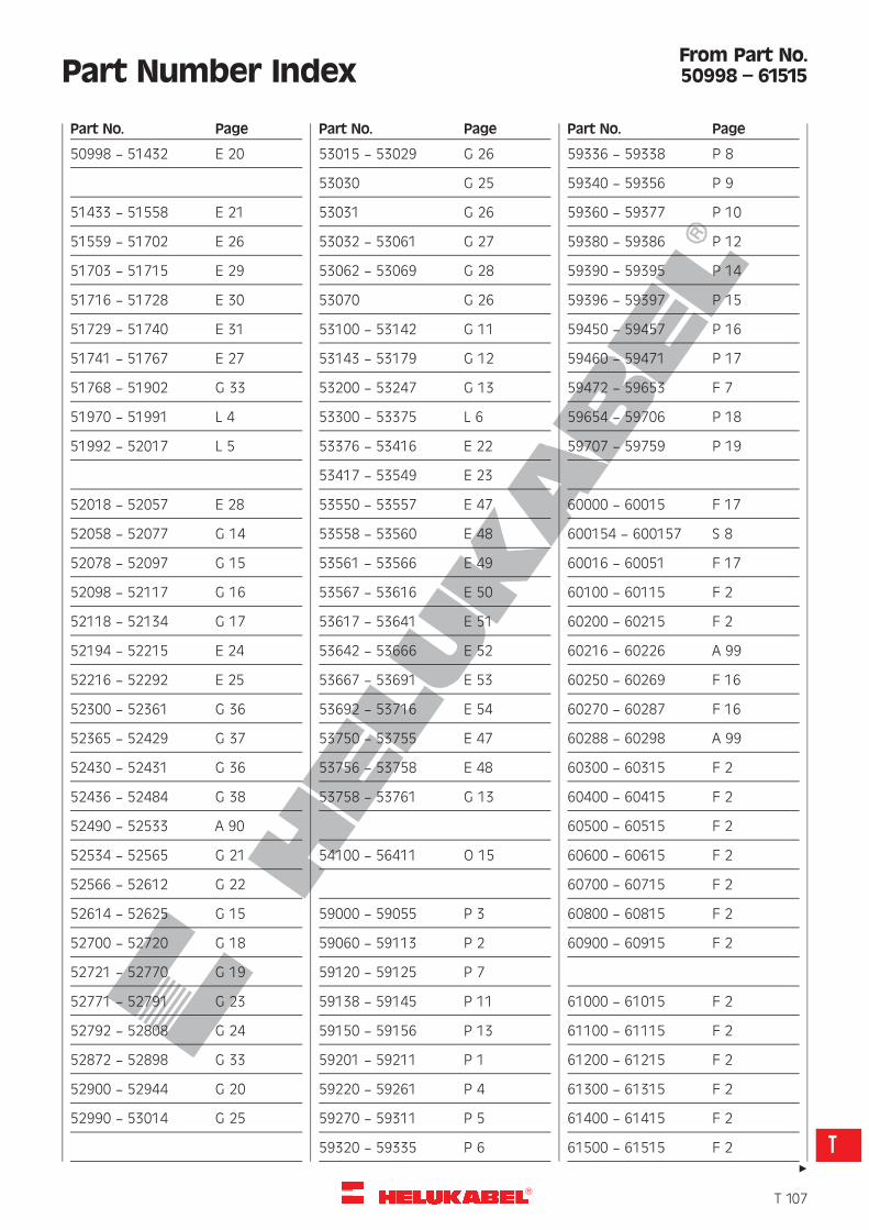
R
Part Number Index
50998 — 51432 E 20
51433 — 51558 E 21
51559 — 51702 E 26
51703 — 51715 E 29
51716 — 51728 E 30
51729 — 51740 E 31
51741 — 51767 E 27
51768 — 51902 G 33
51970 — 51991 L 4
51992 — 52017 L 5
52018 — 52057 E 28
52058 — 52077 G 14
52078 — 52097 G 15
52098 — 52117 G 16
52118 — 52134 G 17
52194 — 52215 E 24
52216 — 52292 E 25
52300 — 52361 G 36
52365 — 52429 G 37
52430 — 52431 G 36
52436 — 52484 G 38
52490 — 52533 A 90
52534 — 52565 G 21
52566 — 52612 G 22
52614 — 52625 G 15
52700 — 52720 G 18
52721 — 52770 G 19
52771 — 52791 G 23
52792 — 52808 G 24
52872 — 52898 G 33
52900 — 52944 G 20
52990 — 53014 G 25
53015 — 53029 G 26
53030 G 25
53031 G 26
53032 — 53061 G 27
53062 — 53069 G 28
53070 G 26
53100 — 53142 G 11
53143 — 53179 G 12
53200 — 53247 G 13
53300 — 53375 L 6
53376 — 53416 E 22
53417 — 53549 E 23
53550 — 53557 E 47
53558 — 53560 E 48
53561 — 53566 E 49
53567 — 53616 E 50
53617 — 53641 E 51
53642 — 53666 E 52
53667 — 53691 E 53
53692 — 53716 E 54
53750 — 53755 E 47
53756 — 53758 E 48
53758 — 53761 G 13
54100 — 56411 O 15
59000 — 59055 P 3
59060 — 59113 P 2
59120 — 59125 P 7
59138 — 59145 P 11
59150 — 59156 P 13
59201 — 59211 P 1
59220 — 59261 P 4
59270 — 59311 P 5
59320 — 59335 P 6
59336 — 59338 P 8
59340 — 59356 P 9
59360 — 59377 P 10
59380 — 59386 P 12
59390 — 59395 P 14
59396 — 59397 P 15
59450 — 59457 P 16
59460 — 59471 P 17
59472 — 59653 F 7
59654 — 59706 P 18
59707 — 59759 P 19
60000 — 60015 F 17
600154 — 600157 S 8
60016 — 60051 F 17
60100 — 60115 F 2
60200 — 60215 F 2
60216 — 60226 A 99
60250 — 60269 F 16
60270 — 60287 F 16
60288 — 60298 A 99
60300 — 60315 F 2
60400 — 60415 F 2
60500 — 60515 F 2
60600 — 60615 F 2
60700 — 60715 F 2
60800 — 60815 F 2
60900 — 60915 F 2
61000 — 61015 F 2
61100 — 61115 F 2
61200 — 61215 F 2
61300 — 61315 F 2
61400 — 61415 F 2
61500 — 61515 F 2
Part No. Page Part No. Page Part No. Page
From Part No.50998 – 61515
"
�T 107
T
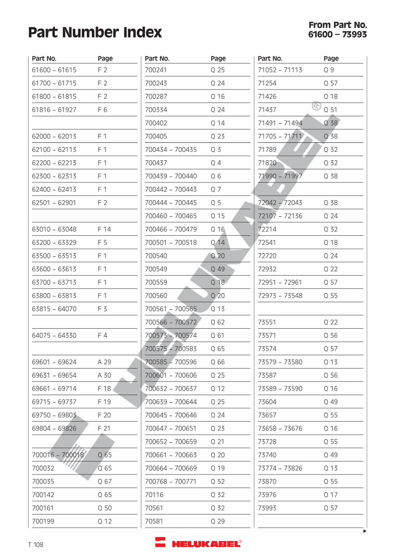
R
Part Number Index
61600 — 61615 F 2
61700 — 61715 F 2
61800 — 61815 F 2
61816 — 61927 F 6
62000 — 62013 F 1
62100 — 62113 F 1
62200 — 62213 F 1
62300 — 62313 F 1
62400 — 62413 F 1
62501 — 62901 F 2
63010 — 63048 F 14
63200 — 63329 F 5
63500 — 63513 F 1
63600 — 63613 F 1
63700 — 63713 F 1
63800 — 63813 F 1
63815 — 64070 F 3
64075 — 64330 F 4
69601 — 69624 A 29
69631 — 69654 A 30
69661 — 69714 F 18
69715 — 69737 F 19
69750 — 69803 F 20
69804 — 69826 F 21
700016 — 700018 Q 65
700032 Q 65
700035 Q 67
700142 Q 65
700161 Q 50
700199 Q 12
700241 Q 25
700243 Q 24
700287 Q 16
700334 Q 24
700402 Q 14
700405 Q 23
700434 — 700435 Q 3
700437 Q 4
700439 — 700440 Q 6
700442 — 700443 Q 7
700444 — 700445 Q 5
700460 — 700465 Q 15
700466 — 700479 Q 16
700501 — 700518 Q 14
700540 Q 20
700549 Q 49
700559 Q 18
700560 Q 20
700561 — 700565 Q 13
700566 — 700572 Q 62
700573 — 700574 Q 61
700575 — 700583 Q 65
700585 — 700596 Q 66
700601 — 700606 Q 25
700632 — 700637 Q 12
700639 — 700644 Q 25
700645 — 700646 Q 24
700647 — 700651 Q 23
700652 — 700659 Q 21
700661 — 700663 Q 20
700664 — 700669 Q 19
700768 — 700771 Q 52
70116 Q 32
70561 Q 32
70581 Q 29
71052 — 71113 Q 9
71254 Q 57
71426 Q 18
71437 Q 51
71491 — 71494 Q 38
71705 — 71711 Q 38
71789 Q 32
71820 Q 32
71990 — 71997 Q 38
72042 — 72043 Q 38
72107 — 72136 Q 24
72214 Q 32
72541 Q 18
72720 Q 24
72932 Q 22
72951 — 72961 Q 57
72973 — 73548 Q 55
73551 Q 22
73571 Q 56
73574 Q 57
73579 — 73580 Q 13
73587 Q 56
73589 — 73590 Q 16
73604 Q 49
73657 Q 55
73658 — 73676 Q 16
73728 Q 55
73740 Q 49
73774 — 73826 Q 13
73870 Q 55
73976 Q 17
73993 Q 57
Part No. Page Part No. Page Part No. Page
From Part No.61600 – 73993
"
�T 108
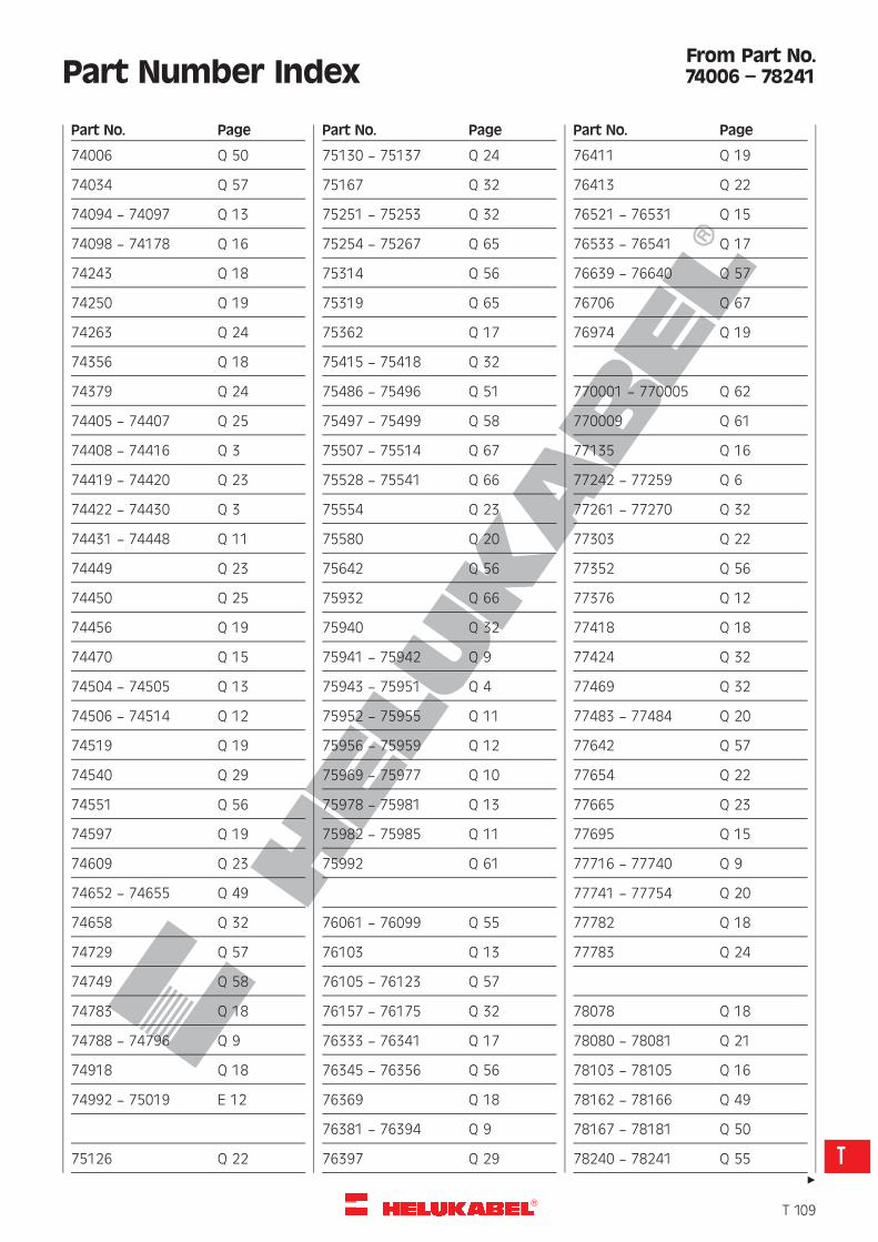
R
Part Number Index
74006 Q 50
74034 Q 57
74094 — 74097 Q 13
74098 — 74178 Q 16
74243 Q 18
74250 Q 19
74263 Q 24
74356 Q 18
74379 Q 24
74405 — 74407 Q 25
74408 — 74416 Q 3
74419 — 74420 Q 23
74422 — 74430 Q 3
74431 — 74448 Q 11
74449 Q 23
74450 Q 25
74456 Q 19
74470 Q 15
74504 — 74505 Q 13
74506 — 74514 Q 12
74519 Q 19
74540 Q 29
74551 Q 56
74597 Q 19
74609 Q 23
74652 — 74655 Q 49
74658 Q 32
74729 Q 57
74749 Q 58
74783 Q 18
74788 — 74796 Q 9
74918 Q 18
74992 — 75019 E 12
75126 Q 22
75130 — 75137 Q 24
75167 Q 32
75251 — 75253 Q 32
75254 — 75267 Q 65
75314 Q 56
75319 Q 65
75362 Q 17
75415 — 75418 Q 32
75486 — 75496 Q 51
75497 — 75499 Q 58
75507 — 75514 Q 67
75528 — 75541 Q 66
75554 Q 23
75580 Q 20
75642 Q 56
75932 Q 66
75940 Q 32
75941 — 75942 Q 9
75943 — 75951 Q 4
75952 — 75955 Q 11
75956 — 75959 Q 12
75969 — 75977 Q 10
75978 — 75981 Q 13
75982 — 75985 Q 11
75992 Q 61
76061 — 76099 Q 55
76103 Q 13
76105 — 76123 Q 57
76157 — 76175 Q 32
76333 — 76341 Q 17
76345 — 76356 Q 56
76369 Q 18
76381 — 76394 Q 9
76397 Q 29
76411 Q 19
76413 Q 22
76521 — 76531 Q 15
76533 — 76541 Q 17
76639 — 76640 Q 57
76706 Q 67
76974 Q 19
770001 — 770005 Q 62
770009 Q 61
77135 Q 16
77242 — 77259 Q 6
77261 — 77270 Q 32
77303 Q 22
77352 Q 56
77376 Q 12
77418 Q 18
77424 Q 32
77469 Q 32
77483 — 77484 Q 20
77642 Q 57
77654 Q 22
77665 Q 23
77695 Q 15
77716 — 77740 Q 9
77741 — 77754 Q 20
77782 Q 18
77783 Q 24
78078 Q 18
78080 — 78081 Q 21
78103 — 78105 Q 16
78162 — 78166 Q 49
78167 — 78181 Q 50
78240 — 78241 Q 55
Part No. Page Part No. Page Part No. Page
From Part No.74006 – 78241
"
�T 109
T

R
Part Number Index
78284 — 78291 Q 56
78358 Q 8
78363 — 78366 Q 23
78367 Q 18
78372 Q 22
78377 — 78479 Q 8
78493 Q 19
78499 Q 30
78522 Q 18
78648 Q 22
78654 Q 23
78689 — 78691 Q 18
78824 Q 16
78828 Q 20
78829 Q 22
78894 Q 20
78938 — 78947 Q 11
78948 — 78952 Q 12
78954 — 78958 Q 13
78963 Q 20
78983 Q 67
78990 N 22
79269 Q 24
79513 Q 20
79514 — 79534 Q 5
79535 — 79552 Q 7
79562 — 79579 Q 14
79613 Q 21
79619 Q 20
79850 — 79907 Q 56
79921 Q 57
80000 – 80003 I 16
800044 I 66
80005 I 16
800067 I 54
800068 I 40
80008 I 16
800086 I 46
800087 I 47
800088 I 55
80010 I 16
800109 I 67
80011 – 80017 I 16
800171 – 800189 I 55
80019 I 16
800190 – 800209 I 55
80021 I 16
800210 – 800213 I 55
800227 – 800239 I 54
80024 I 16
800240 – 800254 I 54
80026 – 80028 I 16
80031 I 17
80032 – 80041 I 16
80043 – 80044 I 52
80045 I 7
80046 – 80048 I 16
800497 I 90
80051 I 16
80053 I 51
800571 I 75
800579 I 4
800647 I 49
800648 I 65
800649 I 67
800650 I 69
800653 – 800654 I 95
800655 I 94
80068 I 51
800680 I 62
800681 – 800682 I 87
800683 – 800684 I 85
800685 I 75
80070 I 51
800708 – 800709 I 19
80071 I 51
800710 I 19
800715 I 69
80072 – 80073 I 50
80074 – 80076 I 52
80084 – 80116 I 17
80118 I 18
80120 – 80130 I 17
80131 – 80138 I 11
80139 – 80146 I 12
80148 – 80155 I 11
80156 – 80162 I 12
80164 – 80171 I 11
80172 – 80178 I 12
80180 – 80187 I 15
80188 – 80195 I 14
80196 – 80204 I 15
80207 – 80211 I 14
80212 – 80218 I 15
80219 I 14
80220 I 15
80223 – 80227 I 14
80228 – 80263 I 15
80264 – 80281 I 9
80294 I 45
80316 I 5
80363 I 23
80369 – 80374 I 10
Part No. Page Part No. Page Part No. Page
From Part No.78284 – 80374
"
�T 110
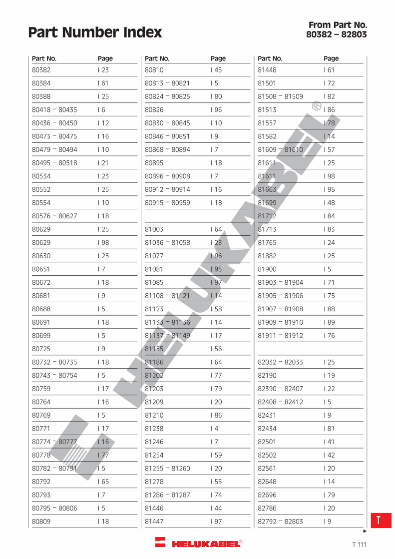
R
Part Number Index
80382 I 23
80384 I 61
80388 I 25
80418 – 80435 I 6
80436 – 80450 I 12
80473 – 80475 I 16
80479 – 80494 I 10
80495 – 80518 I 21
80534 I 23
80552 I 25
80554 I 10
80576 – 80627 I 18
80629 I 25
80629 I 98
80630 I 25
80651 I 7
80672 I 18
80681 I 9
80688 I 5
80691 I 18
80699 I 5
80725 I 9
80732 – 80735 I 18
80743 – 80754 I 5
80759 I 17
80764 I 16
80769 I 5
80771 I 17
80774 – 80777 I 16
80778 I 77
80782 – 80791 I 5
80792 I 65
80793 I 7
80795 – 80806 I 5
80809 I 18
80810 I 45
80813 – 80821 I 5
80824 – 80825 I 80
80826 I 96
80830 – 80845 I 10
80846 – 80851 I 9
80868 – 80894 I 7
80895 I 18
80896 – 80908 I 7
80912 – 80914 I 16
80915 – 80959 I 18
81003 I 64
81036 – 81058 I 23
81077 I 96
81081 I 95
81085 I 97
81108 – 81121 I 14
81123 I 58
81133 – 81136 I 14
81137 – 81149 I 17
81155 I 56
81186 I 64
81202 I 77
81203 I 79
81209 I 20
81210 I 86
81238 I 4
81246 I 7
81254 I 59
81255 – 81260 I 20
81278 I 55
81286 – 81287 I 74
81446 I 44
81447 I 97
81448 I 61
81501 I 72
81508 – 81509 I 82
81513 I 86
81557 I 78
81582 I 14
81609 – 81610 I 57
81611 I 25
81611 I 98
81663 I 95
81699 I 48
81712 I 84
81713 I 83
81765 I 24
81882 I 25
81900 I 5
81903 – 81904 I 71
81905 – 81906 I 75
81907 – 81908 I 88
81909 – 81910 I 89
81911 – 81912 I 76
82032 – 82033 I 25
82190 I 19
82390 – 82407 I 22
82408 – 82412 I 5
82431 I 9
82434 I 81
82501 I 41
82502 I 42
82561 I 20
82648 I 14
82696 I 79
82786 I 20
82792 – 82803 I 9
Part No. Page Part No. Page Part No. Page
From Part No.80382 – 82803
"
�T 111
T
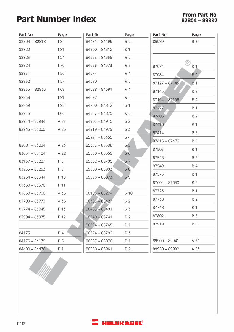
R
Part Number Index
82804 – 82818 I 8
82822 I 81
82823 I 24
82824 I 70
82831 I 56
82832 I 57
82835 – 82836 I 68
82838 I 91
82839 I 92
82913 I 66
82914 — 82944 A 27
82945 — 83000 A 26
83001 — 83024 A 23
83031 — 83104 A 22
83137 — 83227 F 8
83233 — 83253 F 9
83254 — 83344 F 10
83350 — 83370 F 11
83650 — 83708 A 35
83709 — 83773 A 36
83774 — 83845 F 13
83904 — 83975 F 12
84175 R 4
84176 — 84179 R 5
84400 — 84476 R 1
84481 — 84499 R 2
84500 — 84612 S 1
84653 — 84655 R 2
84656 — 84673 R 3
84674 R 4
84680 R 5
84688 — 84691 R 4
84692 R 5
84700 — 84812 S 1
84867 — 84875 R 6
84903 — 84915 S 2
84919 — 84979 S 3
85221 — 85355 S 4
85357 — 85508 S 5
85550 — 85659 S 6
85662 — 85795 S 7
85900 — 85993 S 8
85996 — 86073 S 9
86185 — 86274 S 10
86303 — 86427 S 2
86463 — 86491 S 3
86740 — 86741 R 2
86764 — 86765 R 1
86774 — 86782 R 3
86867 — 86870 R 1
86960 — 86961 R 2
86989 R 3
87074 R 1
87084 R 2
87127 — 87143 R 1
87145 R 2
87164 — 87196 R 4
87277 R 1
87406 R 2
87410 R 1
87414 R 5
87416 — 87476 R 4
87503 R 1
87548 R 3
87549 R 4
87575 R 1
87604 — 87690 R 2
87725 R 1
87738 R 2
87748 R 1
87802 R 3
87919 R 4
89900 — 89941 A 31
89950 — 89992 A 33
Part No. Page Part No. Page Part No. Page
From Part No.82804 – 89992
�T 112
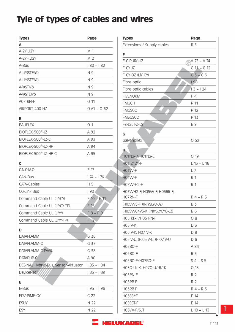
R
Tyle of types of cables and wires
A
A-2Y(L)2Y M 1
A-2YF(L)2Y M 2
A-Bus I 80 — I 82
A-LiY(STE)Yo N 9
A-LiY(STE)Yo N 9
A-Y(ST)Yo N 9
A-Y(STE)Yo N 9
A07 RN-F O 11
AIRPORT 400 HZ Q 61 — Q 62
B
BAUFLEX O 1
BIOFLEX-500�-JZ A 92
BIOFLEX-500�-JZ-C A 93
BIOFLEX-500�-JZ-HF A 94
BIOFLEX-500�-JZ-HF-C A 95
C
C.N.O.M.O F 17
CAN-Bus I 74 — I 76
CATV-Cables H 5
CC-Link Bus I 90
Command Cable UL (LiYCY) F 10 — F 11
Command Cable UL (LiYCY-TP) F 13
Command Cable UL (LiYY) F 8 — F 9
Command Cable UL (LiYY-TP) F 12
D
DATAFLAMM G 36
DATAFLAMM-C G 37
DATAFLAMM-C-PAAR G 38
DATAPUR-C A 90
DESINA� Hybrid-Bus, Sensor-Aktuator I 83 — I 84
DeviceNet� I 85 — I 89
E
E-Bus I 95 — I 96
EDV-PiMF-CY C 22
ESUY N 22
ESY N 22
Extensions / Supply cables R 5
F
F-C-PURo-JZ A 73 — A 74
F-CY-JZ C 11 — C 12
F-CY-OZ (LiY-CY) C 5 — C 6
Fibre optic I 98
Fibre optic cables I 3 — I 24
FIVENORM F 4
FMGCH P 11
FMGSGO P 12
FMSGSGO P 13
FZ-LSi, FZ-LS E 9
G
Galvanoflex Q 52
H
H01N2-D/H01N2-E O 19
H03 Z1Z1-F L 15 — L 16
H03VV-F L 7
H03VV-F R 1
H03VV-H2-F R 1
H03VVH2-F, H05VV-F, H05RR-F,
H07RN-F R 4 — R 5
(H)05VV5-F ((N)YSLYO-JZ) B 3
(H)05VVC4V5-K ((N)YSLYCYO-JZ) B 6
H05 RR-F/H05 RN-F O 8
H05 V-K D 3
H05 V-K, H07 V-K D 8
H05 V-U, (H)05 V-U, (H)07 V-U D 6
H05BQ-F A 84
H05BQ-F R 3
H05BQ-F/H07BQ-F S 4 — S 5
H05G-U/-K, H07G-U/-R/-K O 15
H05RN-F R 2
H05RR-F R 2
H05RR-F R 4 — R 5
H05SS+F E 14
H05SST-F E 14
H05VV-F/SJT L 10 — L 13
Types Page Types Page
"
�T 113
T
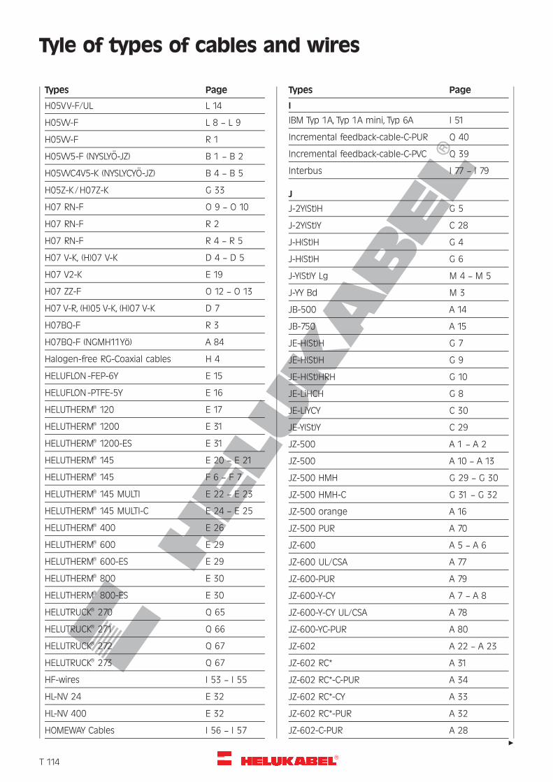
R
Tyle of types of cables and wires
H05VV-F/UL L 14
H05VV-F L 8 — L 9
H05VV-F R 1
H05VV5-F (NYSLYO-JZ) B 1 — B 2
H05VVC4V5-K (NYSLYCYO-JZ) B 4 — B 5
H05Z-K/H07Z-K G 33
H07 RN-F O 9 — O 10
H07 RN-F R 2
H07 RN-F R 4 — R 5
H07 V-K, (H)07 V-K D 4 — D 5
H07 V2-K E 19
H07 ZZ-F O 12 — O 13
H07 V-R, (H)05 V-K, (H)07 V-K D 7
H07BQ-F R 3
H07BQ-F (NGMH11Yo) A 84
Halogen-free RG-Coaxial cables H 4
HELUFLON -FEP-6Y E 15
HELUFLON -PTFE-5Y E 16
HELUTHERM� 120 E 17
HELUTHERM� 1200 E 31
HELUTHERM� 1200-ES E 31
HELUTHERM� 145 E 20 — E 21
HELUTHERM� 145 F 6 — F 7
HELUTHERM� 145 MULTI E 22 — E 23
HELUTHERM� 145 MULTI-C E 24 — E 25
HELUTHERM� 400 E 26
HELUTHERM� 600 E 29
HELUTHERM� 600-ES E 29
HELUTHERM� 800 E 30
HELUTHERM� 800-ES E 30
HELUTRUCK� 270 Q 65
HELUTRUCK� 271 Q 66
HELUTRUCK� 272 Q 67
HELUTRUCK� 273 Q 67
HF-wires I 53 — I 55
HL-NV 24 E 32
HL-NV 400 E 32
HOMEWAY Cables I 56 — I 57
I
IBM Typ 1A, Typ 1A mini, Typ 6A I 51
Incremental feedback-cable-C-PUR Q 40
Incremental feedback-cable-C-PVC Q 39
Interbus I 77 — I 79
J
J-2Y(St)H G 5
J-2Y(St)Y C 28
J-H(St)H G 4
J-H(St)H G 6
J-Y(St)Y Lg M 4 — M 5
J-YY Bd M 3
JB-500 A 14
JB-750 A 15
JE-H(St)H G 7
JE-H(St)H G 9
JE-H(St)HRH G 10
JE-LiHCH G 8
JE-LiYCY C 30
JE-Y(St)Y C 29
JZ-500 A 1 — A 2
JZ-500 A 10 — A 13
JZ-500 HMH G 29 — G 30
JZ-500 HMH-C G 31 — G 32
JZ-500 orange A 16
JZ-500 PUR A 70
JZ-600 A 5 — A 6
JZ-600 UL/CSA A 77
JZ-600-PUR A 79
JZ-600-Y-CY A 7 — A 8
JZ-600-Y-CY UL/CSA A 78
JZ-600-YC-PUR A 80
JZ-602 A 22 — A 23
JZ-602 RC* A 31
JZ-602 RC*-C-PUR A 34
JZ-602 RC*-CY A 33
JZ-602 RC*-PUR A 32
JZ-602-C-PUR A 28
Types Page Types Page
"
�T 114
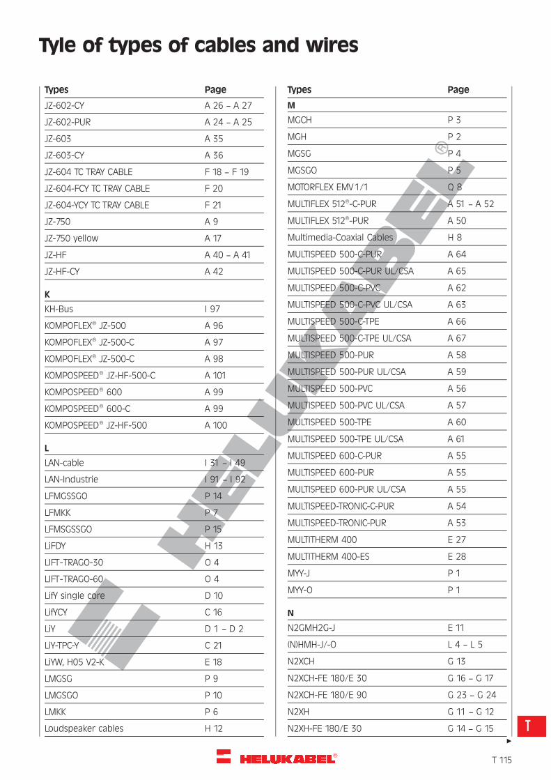
R
Tyle of types of cables and wires
JZ-602-CY A 26 — A 27
JZ-602-PUR A 24 — A 25
JZ-603 A 35
JZ-603-CY A 36
JZ-604 TC TRAY CABLE F 18 — F 19
JZ-604-FCY TC TRAY CABLE F 20
JZ-604-YCY TC TRAY CABLE F 21
JZ-750 A 9
JZ-750 yellow A 17
JZ-HF A 40 — A 41
JZ-HF-CY A 42
K
KH-Bus I 97
KOMPOFLEX� JZ-500 A 96
KOMPOFLEX� JZ-500-C A 97
KOMPOFLEX� JZ-500-C A 98
KOMPOSPEED� JZ-HF-500-C A 101
KOMPOSPEED� 600 A 99
KOMPOSPEED� 600-C A 99
KOMPOSPEED� JZ-HF-500 A 100
L
LAN-cable I 31 — I 49
LAN-Industrie I 91 — I 92
LFMGSSGO P 14
LFMKK P 7
LFMSGSSGO P 15
LiFDY H 13
LIFT-TRAGO-30 O 4
LIFT-TRAGO-60 O 4
LifY single core D 10
LifYCY C 16
LiY D 1 — D 2
LiY-TPC-Y C 21
LiYW, H05 V2-K E 18
LMGSG P 9
LMGSGO P 10
LMKK P 6
Loudspeaker cables H 12
M
MGCH P 3
MGH P 2
MGSG P 4
MGSGO P 5
MOTORFLEX EMV1/1 Q 8
MULTIFLEX 512�-C-PUR A 51 — A 52
MULTIFLEX 512�-PUR A 50
Multimedia-Coaxial Cables H 8
MULTISPEED 500-C-PUR A 64
MULTISPEED 500-C-PUR UL/CSA A 65
MULTISPEED 500-C-PVC A 62
MULTISPEED 500-C-PVC UL/CSA A 63
MULTISPEED 500-C-TPE A 66
MULTISPEED 500-C-TPE UL/CSA A 67
MULTISPEED 500-PUR A 58
MULTISPEED 500-PUR UL/CSA A 59
MULTISPEED 500-PVC A 56
MULTISPEED 500-PVC UL/CSA A 57
MULTISPEED 500-TPE A 60
MULTISPEED 500-TPE UL/CSA A 61
MULTISPEED 600-C-PUR A 55
MULTISPEED 600-PUR A 55
MULTISPEED 600-PUR UL/CSA A 55
MULTISPEED-TRONIC-C-PUR A 54
MULTISPEED-TRONIC-PUR A 53
MULTITHERM 400 E 27
MULTITHERM 400-ES E 28
MYY-J P 1
MYY-O P 1
N
N2GMH2G-J E 11
(N)HMH-J/-O L 4 — L 5
N2XCH G 13
N2XCH-FE 180/E 30 G 16 — G 17
N2XCH-FE 180/E 90 G 23 — G 24
N2XH G 11 — G 12
N2XH-FE 180/E 30 G 14 — G 15
Types Page Types Page
"
�T 115
T
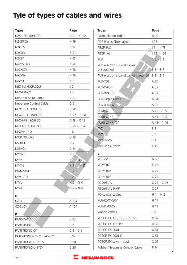
R
Tyle of types of cables and wires
N2XH-FE 180/E 90 G 21 — G 22
N2XS(F)2Y N 19
N2XS2Y N 17
N2XSEY N 21
N2XSY N 15
NA2XS(F)2Y N 20
NA2XS2Y N 18
NA2XSY N 16
NAYY-J N 5
NEO-flat (NGFLGOU) J 2
NEO-flat-CY J 4
Neopren Spiral Cable S 10
Neoprene Control Cable O 2
NHXCH-FE 180/E 30 G 20
NHXCH-FE 180/E 90 G 27 — G 28
NHXH-FE 180/E 30 G 18 — G 19
NHXH-FE 180/E 90 G 25 — G 26
NHXMH-J/-O L 6
NSGAFOU 3KV O 18
NSHTOU O 7
NSSHOU O 14
NYCWY N 8
NYCY N 6 — N 7
NYKY-J N 11 — N 12
(N)YM(St)-J L 3
NYM-J/-O L 2
NYY-J N 2 — N 4
NYY-O N 2 — N 4
O
OZ-BL A 104
OZ-BL-CY A 104
P
PAAR-CY-OZ C 10
PAAR-TRONIC C 7
PAAR-TRONIC-CY C 8 — C 9
PAAR-TRONIC-CY-CY (LiYCY-CY) C 19
PAAR-TRONIC-Li-2YCYv C 20
PAAR-TRONIC-Li-2YCY C 20
Petrol station cable N 10
POF-Plastic fibre cables I 25
PROFIBUS I 61 — I 73
PROFInet I 93 — I 94
PUR S 2 — S 3
PUR electronic spiral cables
unscreened S 6 — S 7
PUR electronic spiral cables screened S 8 — S 9
PUR-750 A 81
PUR-C-PUR A 89
PUR-ORANGE A 82
PUR-Single Cores G 34
PUR-YELLOW A 83
PURo-JZ A 71 — A 72
PURo-JZ-HF A 46 — A 47
PURo-JZ-HF-YCP A 48 — A 49
PVC S 1
PVC-flat J 1
PVC-flat-CY J 3
PVC-Single Cores F 15
R
RD-H(St)H G 35
RD-Y(St)Y C 23
RD-Y(St)Yv C 24
RD-Y(St)YY C 24
RE-2Y(St)Yv C 25 — C 26
RE-2Y(St)Yv PiMF C 27
RG-coaxial cables H 1 — H 3
RGB-KOAX-(St)Y H 11
RGB-KOAX-CY H 11
Ribbon cables J 5
ROBOFLEX 150,...151,...152,...153 Q 32
ROBOFLEX 156-flat Q 30
ROBOFLEX 2001 Q 31
ROBOFLEX 2001-C Q 31
ROBOFLEX sewer robot Q 29
Rubber/Neoprene Control Cable F 14
Types Page Types Page
"
�T 116
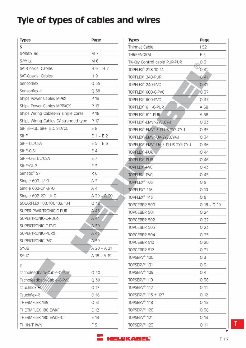
R
Tyle of types of cables and wires
S
S-Y(St)Y Bd M 7
S-YY Lg M 6
SAT-Coaxial Cables H 6 — H 7
SAT-Coaxial Cables H 9
Sensorflex Q 55
Sensorflex-H Q 58
Ships Power Cables MPRX P 18
Ships Power Cables MPRXCX P 19
Ships Wiring Cables-SY single cores P 16
Ships Wiring Cables-SY stranded type P 17
SiF, SiF/GL, SiFF, SiD, SiD/GL E 8
SiHF E 1 — E 2
SiHF UL/CSA E 5 — E 6
SiHF-C-Si E 4
SiHF-C-Si UL/CSA E 7
SiHF/GL-P E 3
Simatic� S7 R 6
Single 600 -J/-O A 3
Single 600-CY -J/-O A 4
Single 602-RC* -J/-O A 29 — A 30
SOLARFLEX 100, 101, 102, 104 Q 49
SUPER-PAAR-TRONIC-C-PUR A 45
SUPERTRONIC-C-PURo A 44
SUPERTRONIC-C-PVC A 39
SUPERTRONIC-PURo A 43
SUPERTRONIC-PVC A 39
SY-JB A 20 — A 21
SY-JZ A 18 — A 19
T
Tachofeedback-Cable-C-PUR Q 40
Tachofeedback-Cable-C-PVC Q 39
Tauchflex-FL O 17
Tauchflex-R O 16
THERMFLEX 145 Q 51
THERMFLEX 180 EWKF E 12
THERMFLEX 180 EWKF-C E 13
THHN/THWN F 5
Thinnet Cable I 52
THREENORM F 3
TK-Key Control cable PUR-PUR O 3
TOPFLEX� 228-10-14 Q 42
TOPFLEX� 240-PUR Q 41
TOPFLEX� 240-PVC Q 41
TOPFLEX� 600-C-PVC Q 37
TOPFLEX� 600-PVC Q 37
TOPFLEX� 611-C-PUR A 68
TOPFLEX� 611-PUR A 68
TOPFLEX�-EMV*-2YSLCY-J Q 33
TOPFLEX�-EMV*-3 PLUS 2YSLCY-J Q 35
TOPFLEX�-EMV*-UV-2YSLCYK-J Q 34
TOPFLEX�-EMV*-UV-3 PLUS 2YSLCY-J Q 36
TOPFLEX�-PUR Q 44
TOPFLEX�-PUR Q 46
TOPFLEX�-PVC Q 43
TOPFLEX�-PVC Q 45
TOPFLEX� 103 Q 9
TOPFLEX� 116 Q 10
TOPFLEX� 143 Q 9
TOPGEBER 500 Q 18 — Q 19
TOPGEBER 501 Q 24
TOPGEBER 502 Q 22
TOPGEBER 503 Q 23
TOPGEBER 504 Q 25
TOPGEBER 510 Q 20
TOPGEBER 512 Q 21
TOPSERV� 100 Q 3
TOPSERV� 101 Q 3
TOPSERV� 109 Q 4
TOPSERV� 110 Q 38
TOPSERV� 112 Q 11
TOPSERV� 113 + 127 Q 12
TOPSERV� 118 Q 15
TOPSERV� 120 Q 38
TOPSERV� 121 Q 13
TOPSERV� 123 Q 11
Types Page Types Page
"
�T 117
T
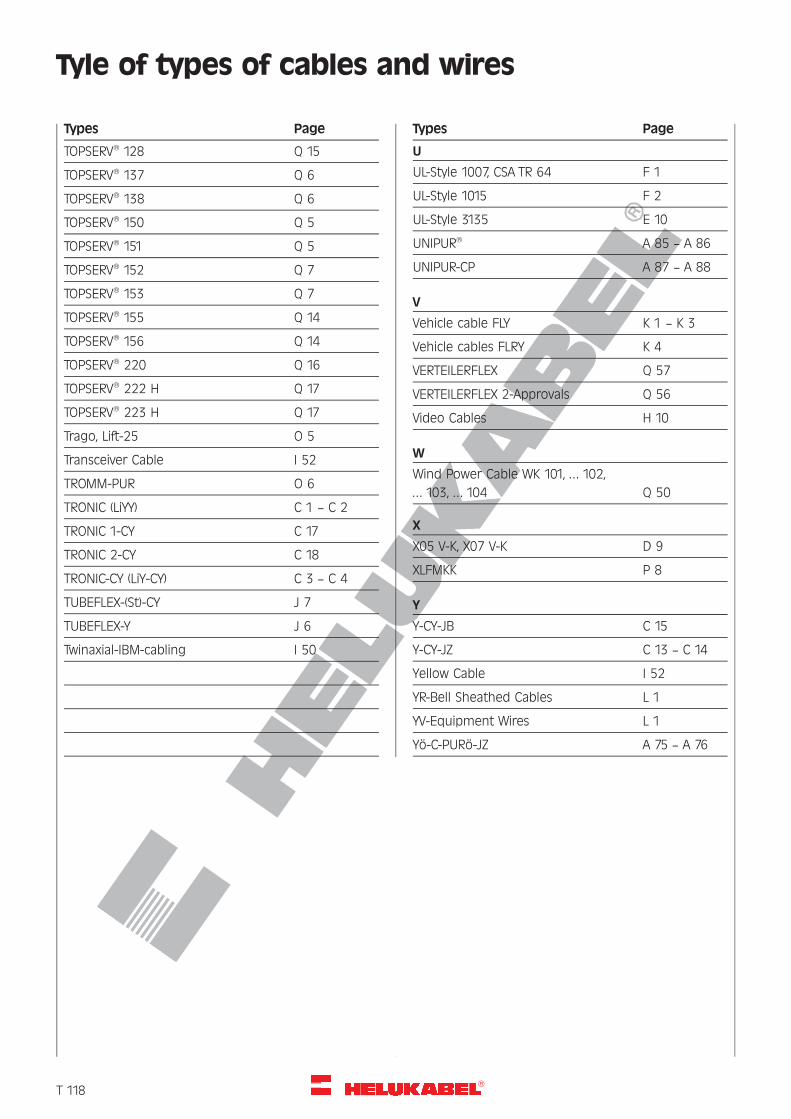
R
Tyle of types of cables and wires
TOPSERV� 128 Q 15
TOPSERV� 137 Q 6
TOPSERV� 138 Q 6
TOPSERV� 150 Q 5
TOPSERV� 151 Q 5
TOPSERV� 152 Q 7
TOPSERV� 153 Q 7
TOPSERV� 155 Q 14
TOPSERV� 156 Q 14
TOPSERV� 220 Q 16
TOPSERV� 222 H Q 17
TOPSERV� 223 H Q 17
Trago, Lift-25 O 5
Transceiver Cable I 52
TROMM-PUR O 6
TRONIC (LiYY) C 1 — C 2
TRONIC 1-CY C 17
TRONIC 2-CY C 18
TRONIC-CY (LiY-CY) C 3 — C 4
TUBEFLEX-(St)-CY J 7
TUBEFLEX-Y J 6
Twinaxial-IBM-cabling I 50
U
UL-Style 1007, CSA TR 64 F 1
UL-Style 1015 F 2
UL-Style 3135 E 10
UNIPUR� A 85 — A 86
UNIPUR-CP A 87 — A 88
V
Vehicle cable FLY K 1 — K 3
Vehicle cables FLRY K 4
VERTEILERFLEX Q 57
VERTEILERFLEX 2-Approvals Q 56
Video Cables H 10
W
Wind Power Cable WK 101, . . . 102,
. . . 103, . . . 104 Q 50
X
X05 V-K, X07 V-K D 9
XLFMKK P 8
Y
Y-CY-JB C 15
Y-CY-JZ C 13 — C 14
Yellow Cable I 52
YR-Bell Sheathed Cables L 1
YV-Equipment Wires L 1
Yo-C-PURo-JZ A 75 — A 76
Types Page Types Page
�T 118
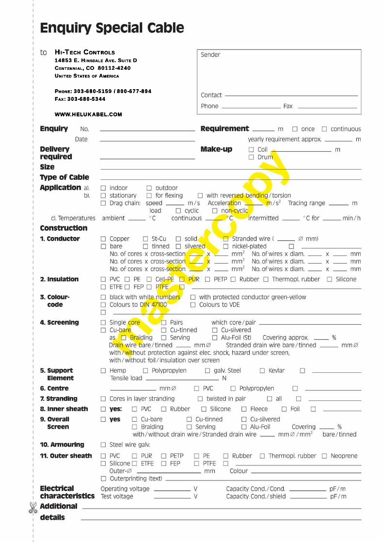
HI-TECH CONTROLS14853 E. HINSDALE AVE. SUITE DCENTENNIAL, CO 80112-4240UNITED STATES OF AMERICA
PHONE: 303-680-5159 / 800-677-894FAX: 303-680-5344
WWWWW.HELUKABEL.COM

HI-TECH CONTROLS14853 E. HINSDALE AVE. SUITE DCENTENNIAL, CO 80112-4240UNITED STATES OF AMERICA
PHONE: 303-680-5159 / 800-677-894FAX: 303-680-5344
WWWWW.HELUKABEL.COM
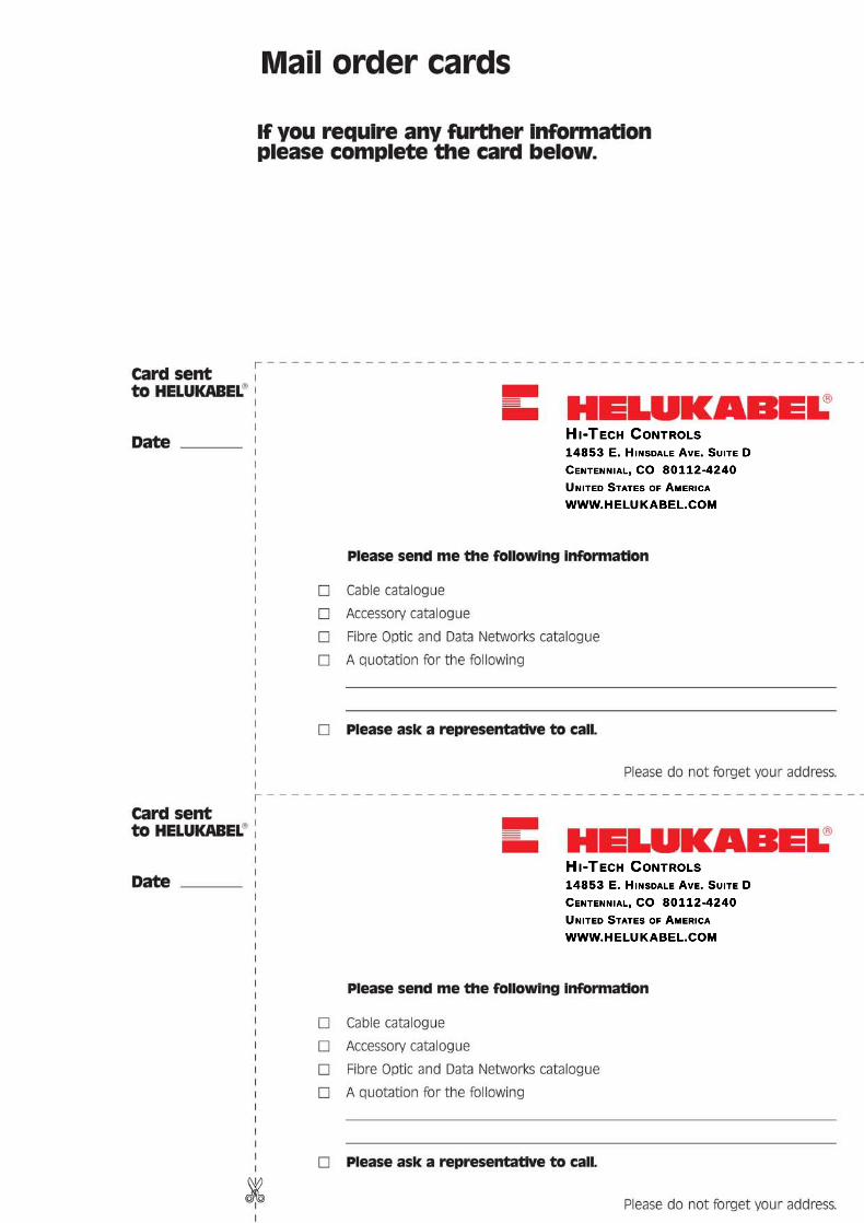
HI-TECH CONTROLS14853 E. HINSDALE AVE. SUITE DCENTENNIAL, CO 80112-4240UNITED STATES OF AMERICA
WWW.HELUKABEL.COM
HI-TECH CONTROLS14853 E. HINSDALE AVE. SUITE DCENTENNIAL, CO 80112-4240UNITED STATES OF AMERICA
WWW.HELUKABEL.COM

HI-TECH CONTROLS14853 E. HINSDALE AVE. SUITE DCENTENNIAL, CO 80112-4240UNITED STATES OF AMERICA
WWW.HELUKABEL.COM
HI-TECH CONTROLS14853 E. HINSDALE AVE. SUITE DCENTENNIAL, CO 80112-4240UNITED STATES OF AMERICA
WWW.HELUKABEL.COM
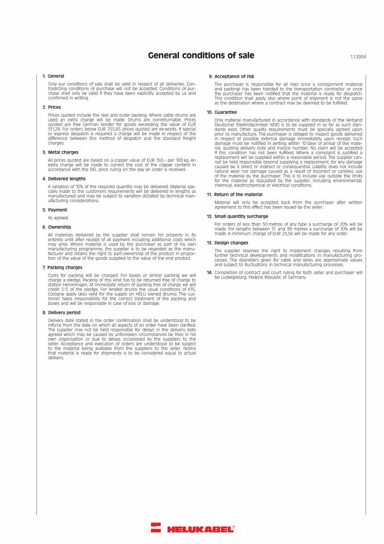
�
General conditions of sale 1.1.2004
1. General
Only our conditions of sale shall be valid in respect of all deliveries. Con-tradicting conditions of purchase will not be accepted. Conditions of pur-chase shall only be valid if they have been explicitly accepted by us andconfirmed in writing.
2. Prices
Prices quoted include the reel and outer packing. Where cable drums areused an extra charge will be made. Drums are nonreturnable. Pricesquoted are free German border for goods exceeding the value of EUR511,29. For orders below EUR 255,65 prices quoted are ex-works. If specialor express despatch is required a charge will be made in respect of thedifference between this method of despatch and the standard freightcharges.
3. Metal charges
All prices quoted are based on a copper value of EUR 150,– per 100 kg. Anextra charge will be made to correct the cost of the copper content inaccordance with the DEL price ruling on the day an order is received.
4. Delivered lengths
A variation of 10% of the required quantity may be delivered. Material spe-cially made to the customers requirements will be delivered in lengths asmanufactured and may be subject to variation dictated by technical man-ufacturing considerations.
5. Payment
As agreed.
6. Ownership
All materials delivered by the supplier shall remain his property in itsentirety until after receipt of all payment including additional costs whichmay arise. Where material is used by the purchaser as part of his ownmanufacturing programme, the supplier is to be regarded as the manu-facturer and retains the right to part-ownership of the product in propor-tion of the value of the goods supplied to the value of the end product.
7. Packing charges
Costs for packing will be charged. For boxes or similar packing we willcharge a pledge. Packing of this kind has to be returned free of charge tostation Hemmingen. At immediate return of packing free of charge we willcredit 2/3 of the pledge. For lended drums the usual conditions of KTG,Cologne apply (also valid for the supply on HELU owned drums). The cus-tomer takes responsibility for the correct treatment of the packing andboxes and will be responsible in case of loss or damage.
8. Delivery period
Delivery date stated in the order confirmation shall be understood to beinforce from the date on which all aspects of an order have been clarified.The supplier may not be held responsible for delays in the delivery dateagreed which may be caused by unforeseen circumstances be they in hisown organisation or due to delays occasioned by the suppliers to theseller. Acceptance and execution of orders are understood to be subjectto the material being available from the suppliers to the seller. Noticethat material is ready for shipments is to be considered equal to actualdelivery.
9. Acceptance of risk
The purchaser is responsible for all risks once a consignment (materialand packing) has been handed to the transportation contractor or oncethe purchaser has been notified that the material is ready for despatch.This condition shall apply also where point of shipment is not the sameas the destination where a contract may be deemed to be fulfilled.
10. Guarantee
Only material manufactured in accordance with standards of the VerbandDeutscher Elektrotechniker (VDE) is to be supplied in so far as such stan-dards exist. Other quality requirements must be specially agreed uponprior to manufacture. The purchaser is obliged to inspect goods deliveredin respect of possible external damage immediately upon receipt. Suchdamage must be notified in writing within 10 days of arrival of the mate-rial, quoting delivery note and invoice number. No claim will be acceptedif this condition has not been fulfilled. Where a complaint is justified areplacement will be supplied within a reasonable period. The supplier can-not be held responsible beyond supplying a replacement, for any damagecaused be it direct or indirect or consequential. Liability does not includenatural wear nor damage caused as a result of incorrect or careless useof the material by the purchaser. This is to include use outside the limitsfor the material as stipulated by the supplier, including environmental,chemical, electrochemical or electrical conditions.
11. Return of the material
Material will only be accepted back from the purchaser after writtenagreement to this effect has been issued by the seller.
12. Small quantity surcharge
For orders of less than 50 metres of any type a surcharge of 20% will bemade. For lengths between 51 and 99 metres a surcharge of 10% will bemade. A minimum charge of EUR 25,56 will be made for any order.
13. Design changes
The supplier reserves the right to implement changes resulting fromfurther technical developments and modifications in manufacturing pro-cesses. The diameters given for cable and wires are approximate valuesand subject to fluctuations in technical manufacturing processes.
14. Completion of contract and court ruling for both seller and purchaser willbe Ludwigsburg, Federal Republic of Germany.