Embed Size (px)
Citation preview

Original instructions, English 27/11/2014 1 / 266This document and the information contained herein, is the exclusive property of SWF Krantechnik GmbH and represents a non-public, confidential and proprietary trade secret that may not be reproduced, disclosed to third parties, altered or otherwise employed in any manner whatsoever without the express written consent of SWF Krantechnik GmbH. Copyright © (2013) SWF Krantechnik GmbH. All rights reserved.
SU
PD
OC
TG
QD
IM30
100-
0 P
S02
505
26.1
1.20
14
TECHNICAL GUIDE FOR HOISTS
Dimensions (SI/50Hz)
SI
SUPDOCTGQDIM3-0.ORD 26.11.2014
- - - -
080674
SWF Krantechnik GmbH Postbox 310410 68264 Mannheim Germany Boehringerstraße 4 68307 Mannheim Germany tel +49(0)621 789-900 fax +49(0)621 789 90-100 [email protected] www.swfkrantechnik.com

TECHNICAL GUIDE FOR HOISTS
English 27/11/2014 2 / 266This document and the information contained herein, is the exclusive property of SWF Krantechnik GmbH and represents a non-public, confidential and proprietary trade secret that may not be reproduced,
disclosed to third parties, altered or otherwise employed in any manner whatsoever without the express written consent of SWF Krantechnik GmbH. Copyright © (2013) SWF Krantechnik GmbH. All rights
reserved.
Table of contents
1 CHANGE HISTORY ........................................................................................................................... 6
LOW HEADROOM TROLLEY .................................................................................................................. 8
2 LOW HEADROOM HOIST NB, REEVING: 02 .................................................................................... 9
3 LOW HEADROOM HOIST NB, REEVING: 04 .................................................................................. 11
4 LOW HEADROOM HOIST NC, REEVING: 02 ................................................................................. 13
5 LOW HEADROOM HOIST NC, REEVING: 04 ................................................................................. 15
6 LOW HEADROOM HOIST NC, REEVING: 04, EXTENDED LOAD .................................................. 17
7 LOW HEADROOM HOIST NC, REEVING: A2 ................................................................................. 19
8 LOW HEADROOM HOIST NC, REEVING: A4 ................................................................................. 21
9 LOW HEADROOM HOIST ND, REEVING: 02 ................................................................................. 23
10 LOW HEADROOM HOIST ND, REEVING: 04 .............................................................................. 25
11 LOW HEADROOM HOIST ND, REEVING: 04, EXTENDED LOAD .............................................. 27
DOUBLE GIRDER TROLLEY, MEDIUM ................................................................................................ 29
12 DOUBLE GIRDER HOIST NB, REEVING: 02 ............................................................................... 31
13 DOUBLE GIRDER HOIST NB, REEVING: 04 ............................................................................... 33
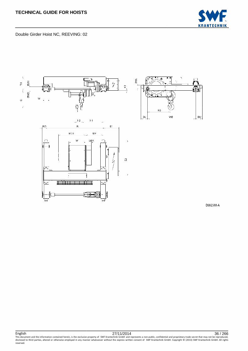
14 DOUBLE GIRDER HOIST NC, REEVING: 02............................................................................... 35
15 DOUBLE GIRDER HOIST NC, REEVING: 04............................................................................... 37
16 DOUBLE GIRDER HOIST ND, REEVING: 02............................................................................... 39
17 DOUBLE GIRDER HOIST ND, REEVING: 04............................................................................... 41
18 DOUBLE GIRDER HOIST ND, REEVING: 06............................................................................... 43
19 DOUBLE GIRDER HOIST ND, REEVING: 08............................................................................... 45
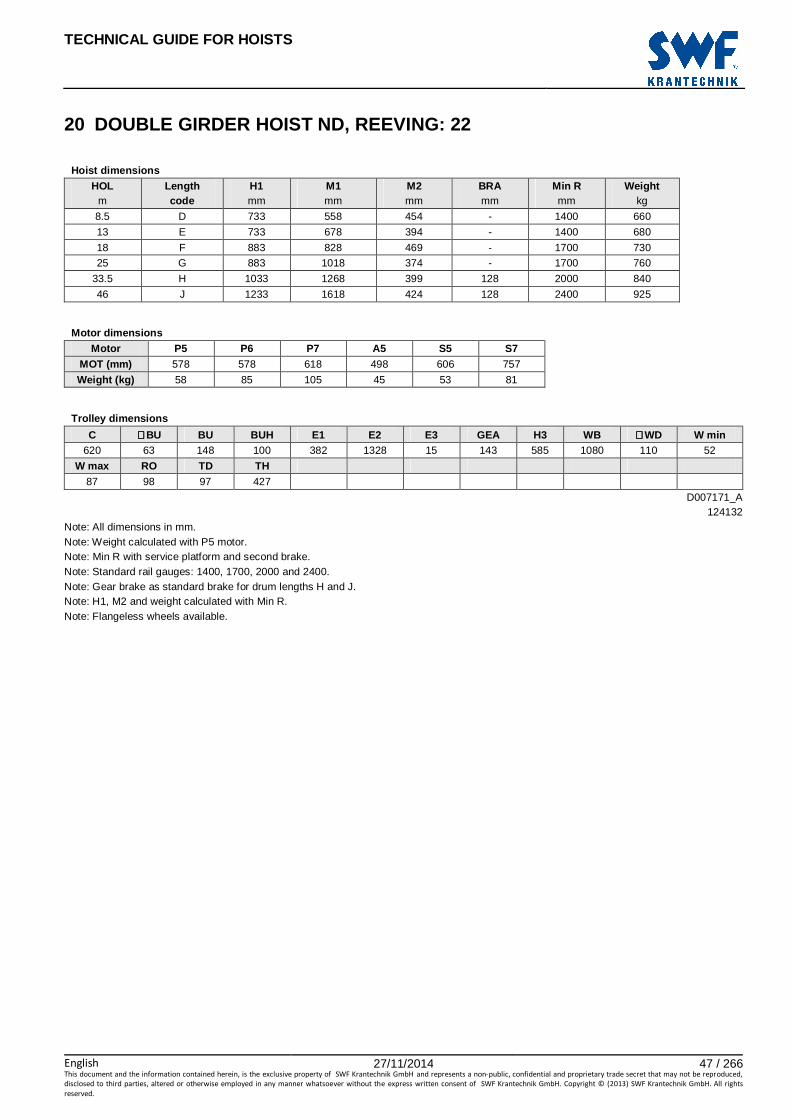
20 DOUBLE GIRDER HOIST ND, REEVING: 22............................................................................... 47
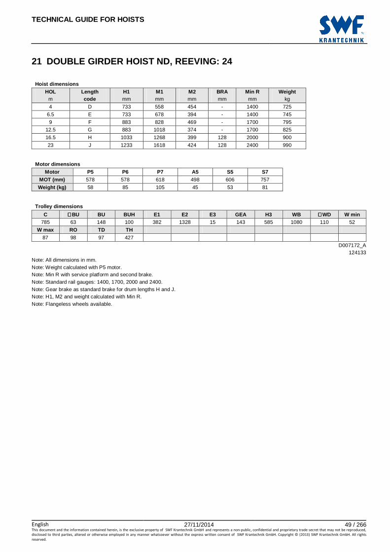
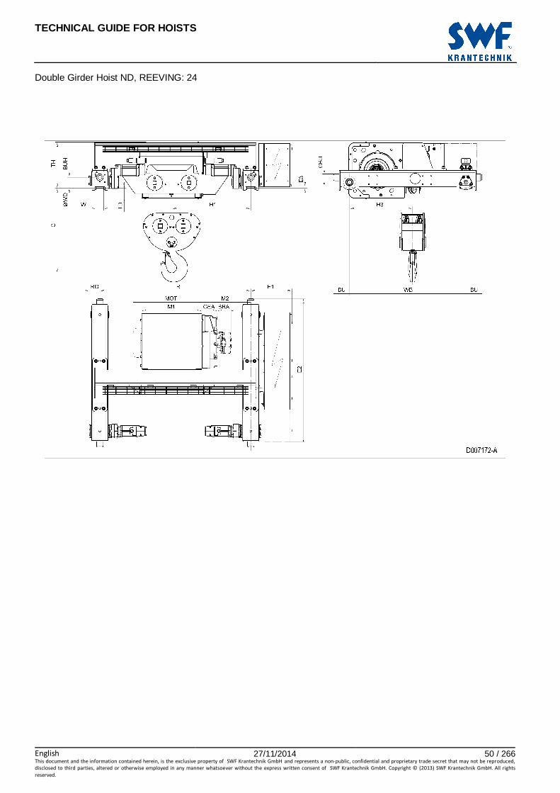
21 DOUBLE GIRDER HOIST ND, REEVING: 24............................................................................... 49
22 DOUBLE GIRDER HOIST ND, REEVING: 26............................................................................... 51
23 DOUBLE GIRDER HOIST ND, REEVING: 28............................................................................... 53
24 DOUBLE GIRDER HOIST NE, REEVING: 02 ............................................................................... 55
25 DOUBLE GIRDER HOIST NE, REEVING: 04 ............................................................................... 57
26 DOUBLE GIRDER HOIST NE, REEVING: 06 ............................................................................... 59
27 DOUBLE GIRDER HOIST NE, REEVING: 08 ............................................................................... 61
28 DOUBLE GIRDER HOIST NE, REEVING: 22 ............................................................................... 63
29 DOUBLE GIRDER HOIST NE, REEVING: 24 ............................................................................... 65
30 DOUBLE GIRDER HOIST NE, REEVING: 26 ............................................................................... 67
31 DOUBLE GIRDER HOIST NE, REEVING: 28 ............................................................................... 69
32 DOUBLE GIRDER HOIST NF, REEVING: 22 ............................................................................... 71
33 DOUBLE GIRDER HOIST NF, REEVING: 24 ............................................................................... 73
34 DOUBLE GIRDER HOIST NF, REEVING: 26 ............................................................................... 75
35 DOUBLE GIRDER HOIST NF, REEVING: 28 ............................................................................... 77
DOUBLE GIRDER TROLLEY, HIGH ...................................................................................................... 79
36 HIGH DOUBLE GIRDER HOIST NB, REEVING: 02 ..................................................................... 81
37 HIGH DOUBLE GIRDER HOIST NB, REEVING: 04 ..................................................................... 83

TECHNICAL GUIDE FOR HOISTS
English 27/11/2014 3 / 266This document and the information contained herein, is the exclusive property of SWF Krantechnik GmbH and represents a non-public, confidential and proprietary trade secret that may not be reproduced,
disclosed to third parties, altered or otherwise employed in any manner whatsoever without the express written consent of SWF Krantechnik GmbH. Copyright © (2013) SWF Krantechnik GmbH. All rights
reserved.
38 HIGH DOUBLE GIRDER HOIST NC, REEVING: 02 .................................................................... 85
39 HIGH DOUBLE GIRDER HOIST NC, REEVING: 04 .................................................................... 87
40 HIGH DOUBLE GIRDER HOIST ND, REEVING: 02 .................................................................... 89
41 HIGH DOUBLE GIRDER HOIST ND, REEVING: 04 .................................................................... 91
42 HIGH DOUBLE GIRDER HOIST ND, REEVING: 06 .................................................................... 93
43 HIGH DOUBLE GIRDER HOIST ND, REEVING: 08 .................................................................... 95
44 HIGH DOUBLE GIRDER HOIST ND, REEVING: 22 .................................................................... 97
45 HIGH DOUBLE GIRDER HOIST ND, REEVING: 24 .................................................................... 99
46 HIGH DOUBLE GIRDER HOIST ND, REEVING: 26 .................................................................. 101
47 HIGH DOUBLE GIRDER HOIST ND, REEVING: 28 .................................................................. 103
DOUBLE GIRDER TROLLEY, LOW .................................................................................................... 105
48 LOW DOUBLE GIRDER HOIST ND, REEVING: 02 ................................................................... 107
49 LOW DOUBLE GIRDER HOIST ND, REEVING: 04 ................................................................... 109
NORMAL HEADROOM TROLLEY ...................................................................................................... 111
50 NORMAL HEADROOM HOIST NB, REEVING: 02 .................................................................... 113
51 NORMAL HEADROOM HOIST NB, REEVING: 04 .................................................................... 115
52 NORMAL HEADROOM HOIST NC, REEVING: 02 .................................................................... 117
53 NORMAL HEADROOM HOIST NC, REEVING: 02, CURVED TRACK ...................................... 119
54 NORMAL HEADROOM HOIST NC, REEVING: 04 .................................................................... 121
55 NORMAL HEADROOM HOIST NC, REEVING: 04, CURVED TRACK ...................................... 123
56 NORMAL HEADROOM HOIST ND, REEVING: 02 .................................................................... 125
57 NORMAL HEADROOM HOIST ND, REEVING: 02, CURVED TRACK ...................................... 127
58 NORMAL HEADROOM HOIST ND, REEVING: 04 .................................................................... 129
59 NORMAL HEADROOM HOIST ND, REEVING: 04, CURVED TRACK ...................................... 131
60 NORMAL HEADROOM HOIST ND, REEVING: 06 .................................................................... 133
61 NORMAL HEADROOM HOIST ND, REEVING: 06, CURVED TRACK ..................................... 135
62 NORMAL HEADROOM HOIST ND, REEVING: 08 .................................................................... 137
63 NORMAL HEADROOM HOIST ND, REEVING: 08, CURVED TRACK ...................................... 139
64 NORMAL HEADROOM HOIST ND, REEVING: 22 .................................................................... 141
65 NORMAL HEADROOM HOIST ND, REEVING: 22, CURVED TRACK ...................................... 143
66 NORMAL HEADROOM HOIST ND, REEVING: 24 .................................................................... 145
67 NORMAL HEADROOM HOIST ND, REEVING: 24, CURVED TRACK ...................................... 147
68 NORMAL HEADROOM HOIST ND, REEVING: 26 .................................................................... 149
69 NORMAL HEADROOM HOIST ND, REEVING: 26, CURVED TRACK ...................................... 151
70 NORMAL HEADROOM HOIST ND, REEVING: 28 .................................................................... 153
71 NORMAL HEADROOM HOIST ND, REEVING: 28, CURVED TRACK ...................................... 155
72 NORMAL HEADROOM HOIST NE, REEVING: 02 .................................................................... 157
73 NORMAL HEADROOM HOIST NE, REEVING: 04 .................................................................... 159
74 NORMAL HEADROOM HOIST NE, REEVING: 06 .................................................................... 161
75 NORMAL HEADROOM HOIST NE, REEVING: 22 .................................................................... 163
76 NORMAL HEADROOM HOIST NE, REEVING: 24 .................................................................... 165
77 NORMAL HEADROOM HOIST NE, REEVING: 26 .................................................................... 167
78 NORMAL HEADROOM HOIST NE, REEVING: 28 .................................................................... 169
FIXED HOIST ...................................................................................................................................... 171
79 FIXED HOIST NB, REEVING: 02 ............................................................................................... 173

TECHNICAL GUIDE FOR HOISTS
English 27/11/2014 4 / 266This document and the information contained herein, is the exclusive property of SWF Krantechnik GmbH and represents a non-public, confidential and proprietary trade secret that may not be reproduced,
disclosed to third parties, altered or otherwise employed in any manner whatsoever without the express written consent of SWF Krantechnik GmbH. Copyright © (2013) SWF Krantechnik GmbH. All rights
reserved.
80 FIXED HOIST NB, REEVING: 04................................................................................................ 175
81 FIXED HOIST NC, REEVING: 02 ............................................................................................... 177
82 FIXED HOIST NC, REEVING: 04 ............................................................................................... 179
83 FIXED HOIST ND, REEVING: 02 ............................................................................................... 181
84 FIXED HOIST ND, REEVING: 04 ............................................................................................... 183
85 FIXED HOIST ND, REEVING: 06 ............................................................................................... 185
86 FIXED HOIST ND, REEVING: 08 ............................................................................................... 187
87 FIXED HOIST ND, REEVING: 22 ............................................................................................... 189
88 FIXED HOIST ND, REEVING: 24 ............................................................................................... 191
89 FIXED HOIST ND, REEVING: 26 ............................................................................................... 193
90 FIXED HOIST ND, REEVING: 28 ............................................................................................... 195
91 FIXED HOIST NE, REEVING: 02................................................................................................ 197
92 FIXED HOIST NE, REEVING: 04................................................................................................ 199
93 FIXED HOIST NE, REEVING: 06................................................................................................ 201
94 FIXED HOIST NE, REEVING: 08................................................................................................ 203
95 FIXED HOIST NE, REEVING: 22................................................................................................ 205
96 FIXED HOIST NE, REEVING: 24................................................................................................ 207
97 FIXED HOIST NE, REEVING: 26................................................................................................ 209
98 FIXED HOIST NE, REEVING: 28................................................................................................ 211
99 FIXED HOIST NF, REEVING: 22 ................................................................................................ 213
100 FIXED HOIST NF, REEVING: 24 ................................................................................................ 215
101 FIXED HOIST NF, REEVING: 26 ................................................................................................ 217
102 FIXED HOIST NF, REEVING: 28 ................................................................................................ 219
MACHINERY HOIST ............................................................................................................................ 221
103 MACHINERY HOIST NBM1V, REEVING: M1............................................................................. 223
104 MACHINERY HOIST NBM2V, REEVING: M2, ROPES TO SAME DIRECTION ......................... 225
105 MACHINERY HOIST NBM2V, REEVING: M2, ROPES TO OPPOSITE DIRECTIONS ............... 227
106 MACHINERY HOIST NCM1V, REEVING: M1 ............................................................................ 229
107 MACHINERY HOIST NCM2V, REEVING: M2, ROPES TO SAME DIRECTION ......................... 231
108 MACHINERY HOIST NCM2V, REEVING: M2, ROPES TO OPPOSITE DIRECTIONS .............. 233
109 MACHINERY HOIST NDM1V, REEVING: M1 ............................................................................ 235
110 MACHINERY HOIST NDM2V, REEVING: M2, ROPES TO SAME DIRECTION ......................... 237
111 MACHINERY HOIST NDM2V, REEVING: M2, ROPES TO OPPOSITE DIRECTIONS .............. 239
112 MACHINERY HOIST NEM1V, REEVING: M1............................................................................. 241
113 MACHINERY HOIST NEM2V, REEVING: M2............................................................................. 243
114 HOIST ELECTRIC CUBICLES ................................................................................................... 245
114.1 Deep-Drawn Hoist Cubicles; ‘QBOX’ ................................................................................................. 245
114.2 External Resistor Cubicle; ‘RBOX’ ..................................................................................................... 245
114.3 Hinged Hoist Cubicles ....................................................................................................................... 247
114.4 Hoist Electric Cubicle Selection With Crane Electric Provisions ......................................................... 249
114.5 Hoist Electric Cubicle Selection With Solo Electric Provisions ............................................................ 251
115 SOLO ELECTRICS IN EXTERNAL CUBICLE, NB/NC/ND LOW HEADROOM AND NORMAL HEADROOM HOISTS .......................................................................................................................... 253
116 HOOK OPERATED ULTIMATE HOISTING LIMIT ...................................................................... 255
117 DOUBLE GIRDER TROLLEY OPTIONAL FEATURES .............................................................. 257
118 SERVICE PLATFORM: DOUBLE GIRDER TROLLEY, MEDIUM ............................................... 259
119 HOOK ......................................................................................................................................... 261

TECHNICAL GUIDE FOR HOISTS
English 27/11/2014 5 / 266This document and the information contained herein, is the exclusive property of SWF Krantechnik GmbH and represents a non-public, confidential and proprietary trade secret that may not be reproduced,
disclosed to third parties, altered or otherwise employed in any manner whatsoever without the express written consent of SWF Krantechnik GmbH. Copyright © (2013) SWF Krantechnik GmbH. All rights
reserved.
119.1 Standard Hook Block Dimensions ..................................................................................................... 261
119.2 Optional Lockable Hook Block Dimensions........................................................................................ 262
119.3 Optional Isolated Hook Block Dimensions ......................................................................................... 263
119.4 Single Hook Forging Dimensions ...................................................................................................... 264
119.5 Ramshorn Hook Forging Dimensions ................................................................................................ 265
120 DRUM AND ROPE SHEAVE DIAMETERS ................................................................................ 266

TECHNICAL GUIDE FOR HOISTS
English 27/11/2014 6 / 266This document and the information contained herein, is the exclusive property of SWF Krantechnik GmbH and represents a non-public, confidential and proprietary trade secret that may not be reproduced,
disclosed to third parties, altered or otherwise employed in any manner whatsoever without the express written consent of SWF Krantechnik GmbH. Copyright © (2013) SWF Krantechnik GmbH. All rights
reserved.
1 CHANGE HISTORY Change Drawing code Table code Modified by Date
Hook orientation corrected. D007219-A ETTPSU 1.2.2013
H3 and H3* corrected. 062190 ETTPSU 19.2.2013
Dimensions PL1, PL2 and weights updated (NE/NF) 135661 ETTPSU 20.2.2013
Buffer extension lengths update; travelling motor side (NE/NF)
135661
ETTPSU 12.3.2013
Two Hoist Trolley removed from manual. D004568-A 063932 ETTPSU 12.3.2013
Two Hoist Trolley removed from manual. D004558-A 063934 ETTPSU 12.3.2013
Two Hoist Trolley removed from manual. D004578-A 063871 ETTPSU 12.3.2013
Two Hoist Trolley removed from manual. D004577-A 063870 ETTPSU 12.3.2013
Two Hoist Trolley removed from manual. D004576-A 063869 ETTPSU 12.3.2013
Two Hoist Trolley removed from manual. D004575-A 063868 ETTPSU 12.3.2013
Two Hoist Trolley removed from manual. D004580-A 063873 ETTPSU 12.3.2013
Two Hoist Trolley removed from manual. D004579-A 063872 ETTPSU 12.3.2013
Two Hoist Trolley removed from manual. D004571-A 063877 ETTPSU 12.3.2013
Two Hoist Trolley removed from manual. D004572-A 063878 ETTPSU 12.3.2013
Two Hoist Trolley removed from manual. D004570-A 063876 ETTPSU 12.3.2013
Two Hoist Trolley removed from manual. D004556-A 063874 ETTPSU 12.3.2013
Two Hoist Trolley removed from manual. D004574-A 063879 ETTPSU 12.3.2013
Two Hoist Trolley removed from manual. D004573-A 064086 ETTPSU 12.3.2013
Two Hoist Trolley removed from manual. D004564-A 063875 ETTPSU 12.3.2013
Dimensions E1 and BF updated (length codes K-N) 101302 ETTPSU 21.5.2013
Dimensions E1 and BF updated (length codes K-N) 101303 ETTPSU 21.5.2013
Dimensions E1 and BF updated (length codes K-N) 101304 ETTPSU 21.5.2013
Dimensions E1 and BF updated (length codes K-N) 101305 ETTPSU 21.5.2013
Dimension R updated (length codes K-N) 102577 ETTPSU 21.5.2013
Dimension R updated (length codes K-N) 102578 ETTPSU 21.5.2013
Dimension R updated (length codes K-N) 102579 ETTPSU 21.5.2013
Dimension R updated (length codes K-N) 102580 ETTPSU 21.5.2013
Dimension W max. updated. 090659 ETTPSU 22.5.2013
Dimension W max. updated. 090660 ETTPSU 22.5.2013
Notes about PU wheels removed; PU wheels not available 135661 ETTPSU 22.5.2013
Added data about hoists with solo electric provisions. D007500-A 157545 ETTPSU 22.5.2013
Added data about hook operated ultimate hoisting limit. 157665 ETTPSU 23.5.2013
Added data about double girder trolley options. D007501-A 157729 ETTPSU 24.5.2013
Added data about ramshorn hook forgings. 102134 ETTPSU 28.5.2013
Added data about optional hooks. 102134 ETTPSU 30.5.2013
RSN20/25 replaced by RFN20/25. 102134 ETTPSU 30.5.2013
C-dimensions changed. 059568 ETTPSU 2.8.2013
C-dimensions changed. 004991 ETTPSU 2.8.2013
C-dimensions changed. 005000 ETTPSU 2.8.2013
C-dimensions changed. 062531 ETTPSU 2.8.2013
C-dimensions changed. 062529 ETTPSU 2.8.2013
C-dimension increases changed. 157665 ETTPSU 2.8.2013
Dimensions R and M2 updated. 102573 ETTPSU 3.11.2013
Dimensions R and M2 updated. M2 added to drawing. D006937-A 102574 ETTPSU 3.11.2013
Dimensions R and M2 updated. 102575 ETTPSU 3.11.2013
Dimensions R and M2 updated. 102576 ETTPSU 3.11.2013
Dimension Max R updated for length codes G/H 090649 ETTPSU 3.11.2013
Dimension Max R updated for length codes G/H 090650 ETTPSU 3.11.2013
Dimension Max R updated for length codes G/H 090651 ETTPSU 3.11.2013
Dimension Max R updated for length codes G/H 090652 ETTPSU 3.11.2013
Dimension Max R updated for length codes K/L/M 090653 ETTPSU 3.11.2013

TECHNICAL GUIDE FOR HOISTS
English 27/11/2014 7 / 266This document and the information contained herein, is the exclusive property of SWF Krantechnik GmbH and represents a non-public, confidential and proprietary trade secret that may not be reproduced,
disclosed to third parties, altered or otherwise employed in any manner whatsoever without the express written consent of SWF Krantechnik GmbH. Copyright © (2013) SWF Krantechnik GmbH. All rights
reserved.
Dimension Max R updated for length codes K/L/M 090654 ETTPSU 3.11.2013
Dimension Max R updated for length codes K/L/M 090655 ETTPSU 3.11.2013
Dimension Max R updated for length codes K/L/M 090656 ETTPSU 3.11.2013
Dimension Max R updated for length codes J/K/L/M 090657 ETTPSU 3.11.2013
Dimension Max R updated for length codes J/K/L/M 090658 ETTPSU 3.11.2013
Dimension Max R updated for length codes J/K/L/M 090659 ETTPSU 3.11.2013
Dimension Max R updated for length codes J/K/L/M 090660 ETTPSU 3.11.2013
C Increase values updated for ND. 157665 ETTPSU 12.03.2014
NC/ND service platform dimensions updated. 135661 ETTPSU 13.03.2014
M2 corrected for length code H. 090660 ETTPSU 17.7.2014
Dimensions rearranged, cubicle selection tables removed. 103527 ETTPSU 3.11.2014
Dimensions rearranged, cubicle selection tables removed. 103528 ETTPSU 3.11.2014
Dimensions rearranged, cubicle selection tables removed. 103529 ETTPSU 3.11.2014
Dimensions rearranged, cubicle selection tables removed. 101302 ETTPSU 3.11.2014
Dimensions rearranged, cubicle selection tables removed. 101303 ETTPSU 3.11.2014
Dimensions rearranged, cubicle selection tables removed. 101304 ETTPSU 3.11.2014
Dimensions rearranged, cubicle selection tables removed. 101305 ETTPSU 3.11.2014
Electric cubicle dimension / selection data added. 191937 ETTPSU 3.11.2014
Data rearranged. D007500-A 157545 ETTPSU 11.11.2014
Dimensions rearranged. 061739 ETTPSU 21.11.2014
Dimensions rearranged. 062124 ETTPSU 21.11.2014
Dimensions rearranged. 001576 ETTPSU 21.11.2014
Dimensions rearranged. 062166 ETTPSU 21.11.2014
Dimensions rearranged. 062511 ETTPSU 21.11.2014
Dimensions rearranged. 062531 ETTPSU 21.11.2014
Dimensions rearranged. 062529 ETTPSU 21.11.2014
Dimensions rearranged. 059568 ETTPSU 21.11.2014
Dimensions rearranged. 004991 ETTPSU 21.11.2014
Dimensions rearranged. 005000 ETTPSU 21.11.2014
Dimensions rearranged. 062129 ETTPSU 21.11.2014
Dimensions rearranged. 062130 ETTPSU 21.11.2014
Dimensions rearranged. 062140 ETTPSU 21.11.2014
Dimensions rearranged. 062168 ETTPSU 21.11.2014
Dimensions rearranged. 062143 ETTPSU 21.11.2014
Dimensions rearranged. 062169 ETTPSU 21.11.2014
Dimensions rearranged. 062272 ETTPSU 21.11.2014
Dimensions rearranged. 062273 ETTPSU 21.11.2014
Dimensions rearranged. 062274 ETTPSU 21.11.2014
Dimensions rearranged. 062275 ETTPSU 21.11.2014
Dimensions rearranged. 124578 ETTPSU 21.11.2014
Dimensions rearranged. 124579 ETTPSU 21.11.2014
Dimensions rearranged. 124580 ETTPSU 21.11.2014
Dimensions rearranged. 124581 ETTPSU 21.11.2014
Dimensions rearranged. 124936 ETTPSU 21.11.2014
Dimensions rearranged. 124937 ETTPSU 21.11.2014
Dimensions rearranged. 124938 ETTPSU 21.11.2014
Dimensions rearranged. 124939 ETTPSU 21.11.2014
Dimensions rearranged. 124940 ETTPSU 21.11.2014
Dimensions rearranged. 124941 ETTPSU 21.11.2014
Dimensions rearranged. 124942 ETTPSU 21.11.2014
Dimensions rearranged. 124943 ETTPSU 21.11.2014

TECHNICAL GUIDE FOR HOISTS
English 27/11/2014 8 / 266This document and the information contained herein, is the exclusive property of SWF Krantechnik GmbH and represents a non-public, confidential and proprietary trade secret that may not be reproduced,
disclosed to third parties, altered or otherwise employed in any manner whatsoever without the express written consent of SWF Krantechnik GmbH. Copyright © (2013) SWF Krantechnik GmbH. All rights
reserved.
LOW HEADROOM TROLLEY

TECHNICAL GUIDE FOR HOISTS
English 27/11/2014 9 / 266This document and the information contained herein, is the exclusive property of SWF Krantechnik GmbH and represents a non-public, confidential and proprietary trade secret that may not be reproduced,
disclosed to third parties, altered or otherwise employed in any manner whatsoever without the express written consent of SWF Krantechnik GmbH. Copyright © (2013) SWF Krantechnik GmbH. All rights
reserved.
2 LOW HEADROOM HOIST NB, REEVING: 02
Hoist dimensions HOL Length M1 H1 H2 H3 H3* H4 BUF Weight
m code mm mm mm mm mm mm mm kg
12 A 326 132 90 495 510 524 368 175
19 C 456 132 144 495 510 524 498 195
Motor dimensions
Motor P1 P2 P3 A3 S3 MOT (mm) 386 446 476 446 526
Weight (kg) 21 31 35 32 28
Trolley dimensions B min. B max. ∅∅∅∅WD ∅∅∅∅BU BU BUH E1 E2 GEA TD TF TH
80 410 80 40 42 28 100 532 110 153 32 248
TW 29
D002075_A 061739
C-dimensions B C
80 - 270 400
271 - 320 430
321 - 370 460
371 - 410 485
Note: All dimensions in mm. Note: Weight calculated with P1 motor. * Please, disregard the dimension H3*.

TECHNICAL GUIDE FOR HOISTS
English 27/11/2014 10 / 266This document and the information contained herein, is the exclusive property of SWF Krantechnik GmbH and represents a non-public, confidential and proprietary trade secret that may not be reproduced,
disclosed to third parties, altered or otherwise employed in any manner whatsoever without the express written consent of SWF Krantechnik GmbH. Copyright © (2013) SWF Krantechnik GmbH. All rights
reserved.
Low Headroom Hoist NB, REEVING: 02

TECHNICAL GUIDE FOR HOISTS
English 27/11/2014 11 / 266This document and the information contained herein, is the exclusive property of SWF Krantechnik GmbH and represents a non-public, confidential and proprietary trade secret that may not be reproduced,
disclosed to third parties, altered or otherwise employed in any manner whatsoever without the express written consent of SWF Krantechnik GmbH. Copyright © (2013) SWF Krantechnik GmbH. All rights
reserved.
3 LOW HEADROOM HOIST NB, REEVING: 04
Hoist dimensions HOL Length M1 H1 H2 H3 H3* H4 BUF Weight
m code mm mm mm mm mm mm mm kg
6 A 326 203 45 495 510 524 368 180
9.5 C 456 203 72 495 510 524 498 200
Motor dimensions
Motor P1 P2 P3 A3 S3 MOT (mm) 386 446 476 446 526
Weight (kg) 21 31 35 32 28
Trolley dimensions B min. B max. ∅∅∅∅WD ∅∅∅∅BU BU BUH E1 E2 GEA TD TF TH
80 410 80 40 42 28 100 461 110 153 32 248
TW 29
D002080_A 062124
C-dimensions B C
80 - 270 350
271 - 320 380
321 - 370 410
371 - 410 435
Note: All dimensions in mm. Note: Weight calculated with P1 motor. * Please, disregard the dimension H3*.

TECHNICAL GUIDE FOR HOISTS
English 27/11/2014 12 / 266This document and the information contained herein, is the exclusive property of SWF Krantechnik GmbH and represents a non-public, confidential and proprietary trade secret that may not be reproduced,
disclosed to third parties, altered or otherwise employed in any manner whatsoever without the express written consent of SWF Krantechnik GmbH. Copyright © (2013) SWF Krantechnik GmbH. All rights
reserved.
Low Headroom Hoist NB, REEVING: 04

TECHNICAL GUIDE FOR HOISTS
English 27/11/2014 13 / 266This document and the information contained herein, is the exclusive property of SWF Krantechnik GmbH and represents a non-public, confidential and proprietary trade secret that may not be reproduced,
disclosed to third parties, altered or otherwise employed in any manner whatsoever without the express written consent of SWF Krantechnik GmbH. Copyright © (2013) SWF Krantechnik GmbH. All rights
reserved.
4 LOW HEADROOM HOIST NC, REEVING: 02
Hoist dimensions HOL Length M1 H1 H2 H3 H3* H4 BUF Weight
m code mm mm mm mm mm mm mm kg
12 B 356 258 95 568 584 536 524 325
18 C 456 258 144 568 584 536 624 345
24 D 556 258 193 568 584 536 724 365
Motor dimensions
Motor P3 P4 A3 S3 S5 MOT (mm) 473 574 443 523 602
Weight (kg) 35 53 32 28 53
Trolley dimensions B min. B max. ∅∅∅∅WD ∅∅∅∅BU BU BUH E1 E2 GEA TD TF TH
100 490 100 63 168 42 8 628 116 203 45 241
TW 38
D002087_A 001576
C-dimensions B C
100 - 250 440
251 - 300 470
301 - 350 505
351 - 400 535
401 - 450 570
451 - 490 595
Note: All dimensions in mm. Note: Weight calculated with P3 motor. Note: Motor S5 is unavailable for load class 3200 kg. * Please, disregard the dimension H3*.

TECHNICAL GUIDE FOR HOISTS
English 27/11/2014 14 / 266This document and the information contained herein, is the exclusive property of SWF Krantechnik GmbH and represents a non-public, confidential and proprietary trade secret that may not be reproduced,
disclosed to third parties, altered or otherwise employed in any manner whatsoever without the express written consent of SWF Krantechnik GmbH. Copyright © (2013) SWF Krantechnik GmbH. All rights
reserved.
Low Headroom Hoist NC, REEVING: 02

TECHNICAL GUIDE FOR HOISTS
English 27/11/2014 15 / 266This document and the information contained herein, is the exclusive property of SWF Krantechnik GmbH and represents a non-public, confidential and proprietary trade secret that may not be reproduced,
disclosed to third parties, altered or otherwise employed in any manner whatsoever without the express written consent of SWF Krantechnik GmbH. Copyright © (2013) SWF Krantechnik GmbH. All rights
reserved.
5 LOW HEADROOM HOIST NC, REEVING: 04
Hoist dimensions HOL Length M1 H1 H2 H3 H3* H4 BUF Weight
m code mm mm mm mm mm mm mm kg
6 B 356 338 49 568 584 536 524 330
9 C 456 338 74 568 584 536 624 350
12 D 556 338 99 568 584 536 724 370
Motor dimensions
Motor P3 P4 A3 S3 S5 MOT (mm) 473 574 443 523 602
Weight (kg) 35 53 32 28 53
Trolley dimensions B min. B max. ∅∅∅∅WD ∅∅∅∅BU BU BUH E1 E2 GEA TD TF TH
100 490 100 63 168 42 8 548 116 203 45 241
TW 38
D002092_A 062166
C-dimensions B C
100 - 199 490
200 - 249 460
250 - 300 425
301 - 350 455
351 - 400 490
401 - 450 520
451 - 490 550
Note: All dimensions in mm. Note: Weight calculated with P3 motor. * Please, disregard the dimension H3*.
TECHNICAL GUIDE FOR HOISTS
English 27/11/2014 16 / 266This document and the information contained herein, is the exclusive property of SWF Krantechnik GmbH and represents a non-public, confidential and proprietary trade secret that may not be reproduced,
disclosed to third parties, altered or otherwise employed in any manner whatsoever without the express written consent of SWF Krantechnik GmbH. Copyright © (2013) SWF Krantechnik GmbH. All rights
reserved.
Low Headroom Hoist NC, REEVING: 04
TECHNICAL GUIDE FOR HOISTS
English 27/11/2014 17 / 266This document and the information contained herein, is the exclusive property of SWF Krantechnik GmbH and represents a non-public, confidential and proprietary trade secret that may not be reproduced,
disclosed to third parties, altered or otherwise employed in any manner whatsoever without the express written consent of SWF Krantechnik GmbH. Copyright © (2013) SWF Krantechnik GmbH. All rights
reserved.
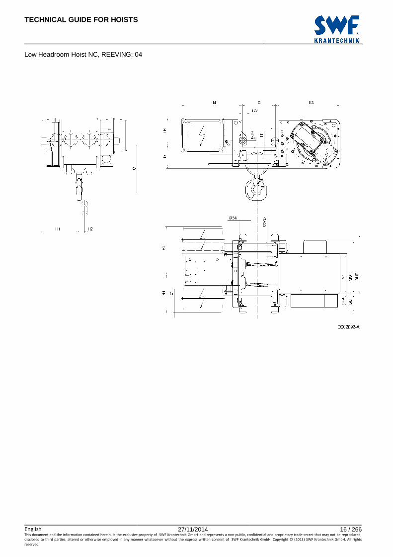
6 LOW HEADROOM HOIST NC, REEVING: 04, EXTENDED LOAD
Hoist dimensions HOL Length M1 H1 H2 H3 H3* H4 BUF Weight
m code mm mm mm mm mm mm mm kg
6 B 356 366 49 574 590 538 524 330
9 C 456 366 74 574 590 538 624 350
12 D 556 366 99 574 590 538 724 370
Motor dimensions
Motor P3 A3 S3 MOT (mm) 473 443 523
Weight (kg) 35 32 28
Trolley dimensions B min. B max. ∅∅∅∅WD ∅∅∅∅BU BU BUH E1 E2 GEA TD TF TH
100 490 125 63 195 41 56 568 116 190 42 253
TW 42
D002093_A 062511
C-dimensions B C
100 - 199 505
200 - 249 470
250 - 300 440
301 - 350 475
351 - 400 505
401 - 450 540
451 - 490 570
Note: All dimensions in mm. Note: Weight calculated with P3 motor. * Please, disregard the dimension H3*.

TECHNICAL GUIDE FOR HOISTS
English 27/11/2014 18 / 266This document and the information contained herein, is the exclusive property of SWF Krantechnik GmbH and represents a non-public, confidential and proprietary trade secret that may not be reproduced,
disclosed to third parties, altered or otherwise employed in any manner whatsoever without the express written consent of SWF Krantechnik GmbH. Copyright © (2013) SWF Krantechnik GmbH. All rights
reserved.
Low Headroom Hoist NC, REEVING: 04, Extended Load

TECHNICAL GUIDE FOR HOISTS
English 27/11/2014 19 / 266This document and the information contained herein, is the exclusive property of SWF Krantechnik GmbH and represents a non-public, confidential and proprietary trade secret that may not be reproduced,
disclosed to third parties, altered or otherwise employed in any manner whatsoever without the express written consent of SWF Krantechnik GmbH. Copyright © (2013) SWF Krantechnik GmbH. All rights
reserved.
7 LOW HEADROOM HOIST NC, REEVING: A2
Hoist dimensions HOL Length M1 H1 H2 H3 H3* H4 BUF Weight
m code mm mm mm mm mm mm mm kg
22.5 C 456 258 144 568 584 536 624 320
30 D 556 258 193 568 584 536 724 340
Motor dimensions
Motor P2 P4 A3 S3 S5 MOT (mm) 446 574 443 523 602
Weight (kg) 35 53 32 28 53
Trolley dimensions B min. B max ∅∅∅∅WD ∅∅∅∅BU BU BUH E1 E2 GEA TD TF TH
100 490 100 63 168 42 8 628 116 203 45 241
TW 38
D002106_A 062531
C-dimensions B C
100 - 300 450
301 - 350 475
351 - 400 505
401 - 450 540
451 - 490 570
Note: All dimensions in mm. Note: Weight calculated with P2 motor. * Please, disregard the dimension H3*.
TECHNICAL GUIDE FOR HOISTS
English 27/11/2014 20 / 266This document and the information contained herein, is the exclusive property of SWF Krantechnik GmbH and represents a non-public, confidential and proprietary trade secret that may not be reproduced,
disclosed to third parties, altered or otherwise employed in any manner whatsoever without the express written consent of SWF Krantechnik GmbH. Copyright © (2013) SWF Krantechnik GmbH. All rights
reserved.
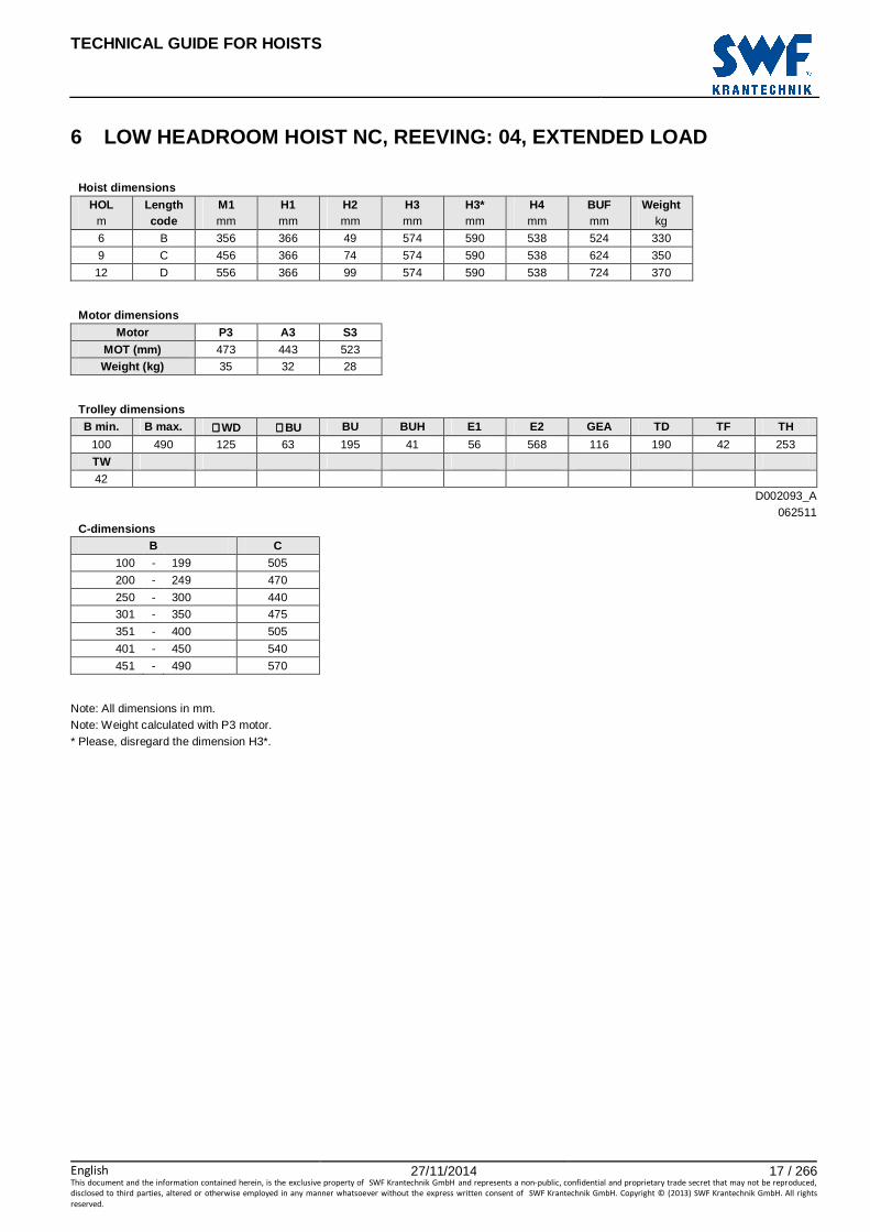
Low Headroom Hoist NC, REEVING: A2

TECHNICAL GUIDE FOR HOISTS
English 27/11/2014 21 / 266This document and the information contained herein, is the exclusive property of SWF Krantechnik GmbH and represents a non-public, confidential and proprietary trade secret that may not be reproduced,
disclosed to third parties, altered or otherwise employed in any manner whatsoever without the express written consent of SWF Krantechnik GmbH. Copyright © (2013) SWF Krantechnik GmbH. All rights
reserved.
8 LOW HEADROOM HOIST NC, REEVING: A4
Hoist dimensions HOL Length M1 H1 H2 H3 H3* H4 BUF Weight
m code mm mm mm mm mm mm mm kg
11 C 456 318 73 568 584 536 624 335
15 D 556 318 99 568 584 536 724 355
Motor dimensions
Motor P2 P4 A3 S3 S5 MOT (mm) 446 574 443 523 602
Weight (kg) 35 53 32 28 53
Trolley dimensions B min. B max. ∅∅∅∅WD ∅∅∅∅BU BU BUH E1 E2 GEA TD TF TH
100 490 100 63 168 42 8 568 116 203 45 241
TW 38
D002107_A 062529
C-dimensions B C
100 - 300 380
301 - 350 415
351 - 400 445
401 - 450 480
451 - 490 510
Note: All dimensions in mm. Note: Weight calculated with P2 motor. * Please, disregard the dimension H3*.

TECHNICAL GUIDE FOR HOISTS
English 27/11/2014 22 / 266This document and the information contained herein, is the exclusive property of SWF Krantechnik GmbH and represents a non-public, confidential and proprietary trade secret that may not be reproduced,
disclosed to third parties, altered or otherwise employed in any manner whatsoever without the express written consent of SWF Krantechnik GmbH. Copyright © (2013) SWF Krantechnik GmbH. All rights
reserved.
Low Headroom Hoist NC, REEVING: A4
TECHNICAL GUIDE FOR HOISTS
English 27/11/2014 23 / 266This document and the information contained herein, is the exclusive property of SWF Krantechnik GmbH and represents a non-public, confidential and proprietary trade secret that may not be reproduced,
disclosed to third parties, altered or otherwise employed in any manner whatsoever without the express written consent of SWF Krantechnik GmbH. Copyright © (2013) SWF Krantechnik GmbH. All rights
reserved.
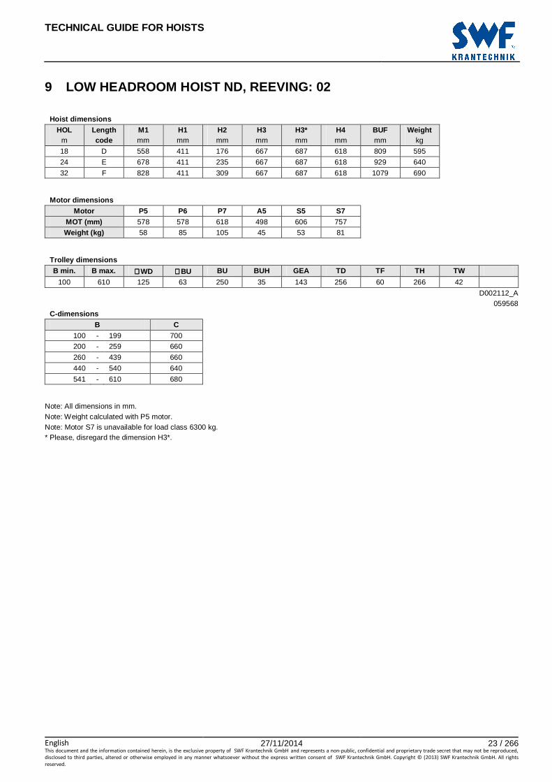
9 LOW HEADROOM HOIST ND, REEVING: 02
Hoist dimensions HOL Length M1 H1 H2 H3 H3* H4 BUF Weight
m code mm mm mm mm mm mm mm kg
18 D 558 411 176 667 687 618 809 595
24 E 678 411 235 667 687 618 929 640
32 F 828 411 309 667 687 618 1079 690
Motor dimensions
Motor P5 P6 P7 A5 S5 S7 MOT (mm) 578 578 618 498 606 757
Weight (kg) 58 85 105 45 53 81
Trolley dimensions B min. B max. ∅∅∅∅WD ∅∅∅∅BU BU BUH GEA TD TF TH TW
100 610 125 63 250 35 143 256 60 266 42
D002112_A 059568
C-dimensions B C
100 - 199 700
200 - 259 660
260 - 439 660
440 - 540 640
541 - 610 680
Note: All dimensions in mm. Note: Weight calculated with P5 motor. Note: Motor S7 is unavailable for load class 6300 kg. * Please, disregard the dimension H3*.

TECHNICAL GUIDE FOR HOISTS
English 27/11/2014 24 / 266This document and the information contained herein, is the exclusive property of SWF Krantechnik GmbH and represents a non-public, confidential and proprietary trade secret that may not be reproduced,
disclosed to third parties, altered or otherwise employed in any manner whatsoever without the express written consent of SWF Krantechnik GmbH. Copyright © (2013) SWF Krantechnik GmbH. All rights
reserved.
Low Headroom Hoist ND, REEVING: 02

TECHNICAL GUIDE FOR HOISTS
English 27/11/2014 25 / 266This document and the information contained herein, is the exclusive property of SWF Krantechnik GmbH and represents a non-public, confidential and proprietary trade secret that may not be reproduced,
disclosed to third parties, altered or otherwise employed in any manner whatsoever without the express written consent of SWF Krantechnik GmbH. Copyright © (2013) SWF Krantechnik GmbH. All rights
reserved.
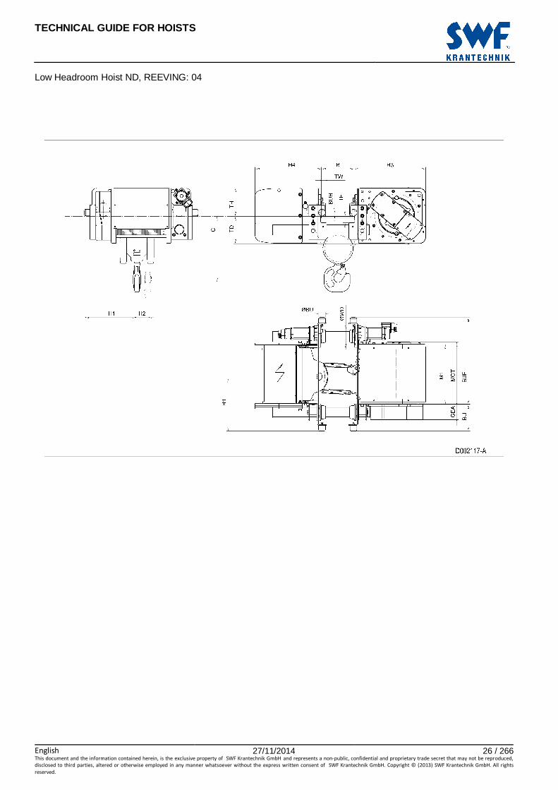
10 LOW HEADROOM HOIST ND, REEVING: 04
Hoist dimensions HOL Length M1 H1 H2 H3 H3* H4 BUF Weight
m code mm mm mm mm mm mm mm kg
9 D 558 489 88 667 687 618 809 610
12 E 678 489 118 667 687 618 929 660
16 F 828 489 156 667 687 618 1079 710
Motor dimensions
Motor P5 P6 P7 A5 S5 S7 MOT (mm) 578 578 618 498 606 757
Weight (kg) 58 85 105 45 53 81
Trolley dimensions B min. B max. ∅∅∅∅WD ∅∅∅∅BU BU BUH GEA TD TF TH TW
100 610 125 63 250 35 143 256 60 266 42
D002117_A 004991
C-dimensions B C
100 - 199 660
200 - 289 630
290 - 530 600
531 - 610 650
Note: All dimensions in mm. Note: Weight calculated with P5 motor. * Please, disregard the dimension H3*.
TECHNICAL GUIDE FOR HOISTS
English 27/11/2014 26 / 266This document and the information contained herein, is the exclusive property of SWF Krantechnik GmbH and represents a non-public, confidential and proprietary trade secret that may not be reproduced,
disclosed to third parties, altered or otherwise employed in any manner whatsoever without the express written consent of SWF Krantechnik GmbH. Copyright © (2013) SWF Krantechnik GmbH. All rights
reserved.
Low Headroom Hoist ND, REEVING: 04
TECHNICAL GUIDE FOR HOISTS
English 27/11/2014 27 / 266This document and the information contained herein, is the exclusive property of SWF Krantechnik GmbH and represents a non-public, confidential and proprietary trade secret that may not be reproduced,
disclosed to third parties, altered or otherwise employed in any manner whatsoever without the express written consent of SWF Krantechnik GmbH. Copyright © (2013) SWF Krantechnik GmbH. All rights
reserved.
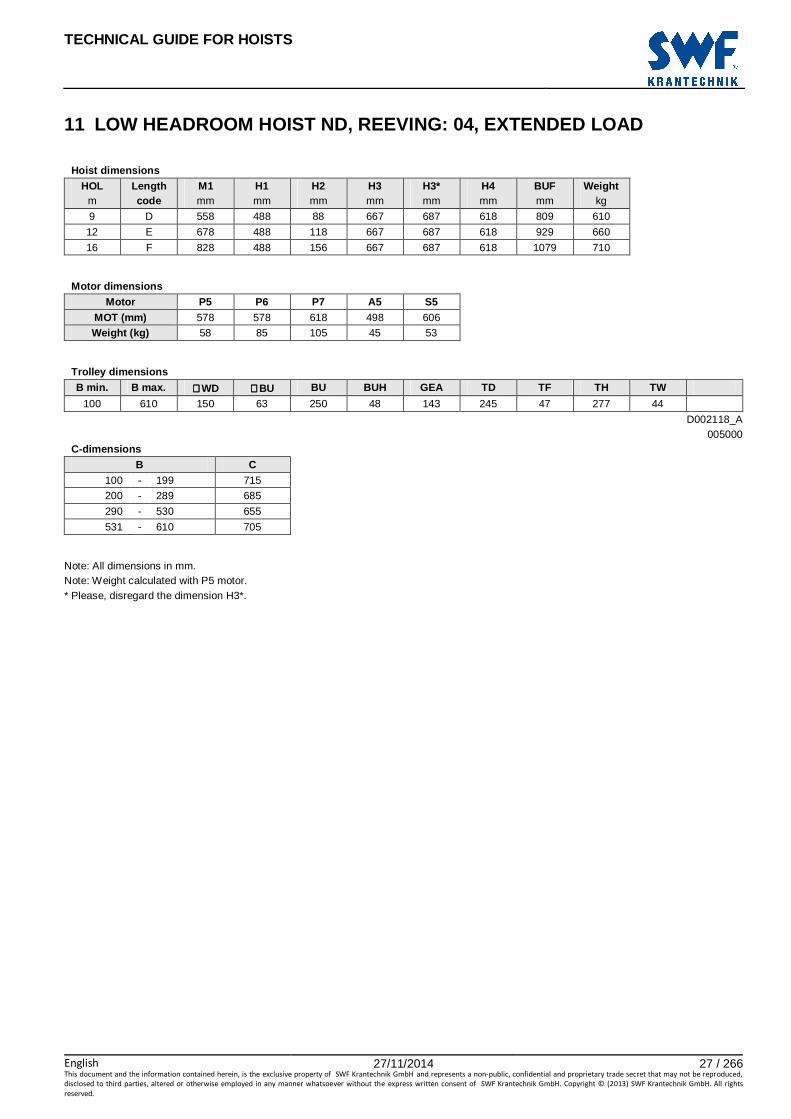
11 LOW HEADROOM HOIST ND, REEVING: 04, EXTENDED LOA D
Hoist dimensions HOL Length M1 H1 H2 H3 H3* H4 BUF Weight
m code mm mm mm mm mm mm mm kg
9 D 558 488 88 667 687 618 809 610
12 E 678 488 118 667 687 618 929 660
16 F 828 488 156 667 687 618 1079 710
Motor dimensions
Motor P5 P6 P7 A5 S5 MOT (mm) 578 578 618 498 606
Weight (kg) 58 85 105 45 53
Trolley dimensions B min. B max. ∅∅∅∅WD ∅∅∅∅BU BU BUH GEA TD TF TH TW
100 610 150 63 250 48 143 245 47 277 44
D002118_A 005000
C-dimensions B C
100 - 199 715
200 - 289 685
290 - 530 655
531 - 610 705
Note: All dimensions in mm. Note: Weight calculated with P5 motor. * Please, disregard the dimension H3*.

TECHNICAL GUIDE FOR HOISTS
English 27/11/2014 28 / 266This document and the information contained herein, is the exclusive property of SWF Krantechnik GmbH and represents a non-public, confidential and proprietary trade secret that may not be reproduced,
disclosed to third parties, altered or otherwise employed in any manner whatsoever without the express written consent of SWF Krantechnik GmbH. Copyright © (2013) SWF Krantechnik GmbH. All rights
reserved.
Low Headroom Hoist ND, REEVING: 04, Extended Load

TECHNICAL GUIDE FOR HOISTS
English 27/11/2014 29 / 266This document and the information contained herein, is the exclusive property of SWF Krantechnik GmbH and represents a non-public, confidential and proprietary trade secret that may not be reproduced,
disclosed to third parties, altered or otherwise employed in any manner whatsoever without the express written consent of SWF Krantechnik GmbH. Copyright © (2013) SWF Krantechnik GmbH. All rights
reserved.
DOUBLE GIRDER TROLLEY, MEDIUM

TECHNICAL GUIDE FOR HOISTS
English 27/11/2014 30 / 266This document and the information contained herein, is the exclusive property of SWF Krantechnik GmbH and represents a non-public, confidential and proprietary trade secret that may not be reproduced,
disclosed to third parties, altered or otherwise employed in any manner whatsoever without the express written consent of SWF Krantechnik GmbH. Copyright © (2013) SWF Krantechnik GmbH. All rights
reserved.

TECHNICAL GUIDE FOR HOISTS
English 27/11/2014 31 / 266This document and the information contained herein, is the exclusive property of SWF Krantechnik GmbH and represents a non-public, confidential and proprietary trade secret that may not be reproduced,
disclosed to third parties, altered or otherwise employed in any manner whatsoever without the express written consent of SWF Krantechnik GmbH. Copyright © (2013) SWF Krantechnik GmbH. All rights
reserved.
12 DOUBLE GIRDER HOIST NB, REEVING: 02
Hoist dimensions HOL Length M1 M2 H1 H2 Min R Weight
m code mm mm mm mm mm kg
12 A 326 424 519 90 1200 220
19 C 456 424 519 144 1200 230
Motor dimensions
Motor P1 P2 P3 A3 S3 MOT (mm) 386 446 476 446 526
Weight (kg) 21 31 35 32 28
Trolley dimensions
C ∅∅∅∅BU BU BUH E1 E2 E3 GEA H3 WB ∅∅∅∅WD W min
320 63 138 90 327 714 15 110 398 820 90 50
W max RO TD TH 70 83 113 268
D002076_A 062126
Note: All dimensions in mm. Note: H1, M2 and weight calculated with P1 motor and Min R. Note: Min R with second brake. Note: Standard rail gauges: 1200, 1400, 1700 and 2000. Note: Flangeless wheels available.

TECHNICAL GUIDE FOR HOISTS
English 27/11/2014 32 / 266This document and the information contained herein, is the exclusive property of SWF Krantechnik GmbH and represents a non-public, confidential and proprietary trade secret that may not be reproduced,
disclosed to third parties, altered or otherwise employed in any manner whatsoever without the express written consent of SWF Krantechnik GmbH. Copyright © (2013) SWF Krantechnik GmbH. All rights
reserved.
Double Girder Hoist NB, REEVING: 02
TECHNICAL GUIDE FOR HOISTS
English 27/11/2014 33 / 266This document and the information contained herein, is the exclusive property of SWF Krantechnik GmbH and represents a non-public, confidential and proprietary trade secret that may not be reproduced,
disclosed to third parties, altered or otherwise employed in any manner whatsoever without the express written consent of SWF Krantechnik GmbH. Copyright © (2013) SWF Krantechnik GmbH. All rights
reserved.
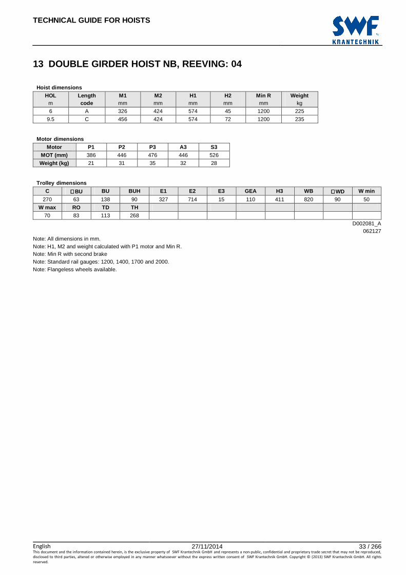
13 DOUBLE GIRDER HOIST NB, REEVING: 04
Hoist dimensions HOL Length M1 M2 H1 H2 Min R Weight
m code mm mm mm mm mm kg
6 A 326 424 574 45 1200 225
9.5 C 456 424 574 72 1200 235
Motor dimensions
Motor P1 P2 P3 A3 S3 MOT (mm) 386 446 476 446 526
Weight (kg) 21 31 35 32 28
Trolley dimensions
C ∅∅∅∅BU BU BUH E1 E2 E3 GEA H3 WB ∅∅∅∅WD W min
270 63 138 90 327 714 15 110 411 820 90 50
W max RO TD TH 70 83 113 268
D002081_A 062127
Note: All dimensions in mm. Note: H1, M2 and weight calculated with P1 motor and Min R. Note: Min R with second brake Note: Standard rail gauges: 1200, 1400, 1700 and 2000. Note: Flangeless wheels available.

TECHNICAL GUIDE FOR HOISTS
English 27/11/2014 34 / 266This document and the information contained herein, is the exclusive property of SWF Krantechnik GmbH and represents a non-public, confidential and proprietary trade secret that may not be reproduced,
disclosed to third parties, altered or otherwise employed in any manner whatsoever without the express written consent of SWF Krantechnik GmbH. Copyright © (2013) SWF Krantechnik GmbH. All rights
reserved.
Double Girder Hoist NB, REEVING: 04

TECHNICAL GUIDE FOR HOISTS
English 27/11/2014 35 / 266This document and the information contained herein, is the exclusive property of SWF Krantechnik GmbH and represents a non-public, confidential and proprietary trade secret that may not be reproduced,
disclosed to third parties, altered or otherwise employed in any manner whatsoever without the express written consent of SWF Krantechnik GmbH. Copyright © (2013) SWF Krantechnik GmbH. All rights
reserved.
14 DOUBLE GIRDER HOIST NC, REEVING: 02
Hoist dimensions HOL Length M1 M2 H1 H2 Min R Weight
m code mm mm mm mm mm kg
12 B 356 368 459 95 1200 310
18 C 456 368 459 144 1200 320
24 D 556 468 559 193 1400 335
30 E 676 468 559 252 1400 350
Motor dimensions
Motor P3 P4 A3 S3 S5 MOT (mm) 473 574 443 523 602
Weight (kg) 35 53 32 28 53
Trolley dimensions
C ∅∅∅∅BU BU BUH E1 E2 E3 GEA H3 WB ∅∅∅∅WD W min
360 63 138 90 327 758 12 116 482 1010 90 50
W max RO TD TH 70 83 126 304
D002088_A 062138
Note: All dimensions in mm. Note: H1, M2 and weight calculated with P3 motor and Min R. Note: Motor S5 is unavailable for load class 3200 kg. Note: Min R with service platform and second brake. Note: Standard rail gauges: 1200, 1400, 1700 and 2000. Note: Flangeless wheels available.
TECHNICAL GUIDE FOR HOISTS
English 27/11/2014 36 / 266This document and the information contained herein, is the exclusive property of SWF Krantechnik GmbH and represents a non-public, confidential and proprietary trade secret that may not be reproduced,
disclosed to third parties, altered or otherwise employed in any manner whatsoever without the express written consent of SWF Krantechnik GmbH. Copyright © (2013) SWF Krantechnik GmbH. All rights
reserved.
Double Girder Hoist NC, REEVING: 02

TECHNICAL GUIDE FOR HOISTS
English 27/11/2014 37 / 266This document and the information contained herein, is the exclusive property of SWF Krantechnik GmbH and represents a non-public, confidential and proprietary trade secret that may not be reproduced,
disclosed to third parties, altered or otherwise employed in any manner whatsoever without the express written consent of SWF Krantechnik GmbH. Copyright © (2013) SWF Krantechnik GmbH. All rights
reserved.
15 DOUBLE GIRDER HOIST NC, REEVING: 04
Hoist dimensions HOL Length M1 M2 H1 H2 Min R Weight
m code mm mm mm mm mm kg
6 B 356 368 537 49 1200 315
9 C 456 368 537 74 1200 325
12 D 556 468 637 99 1400 340
15 E 676 468 637 129 1400 360
Motor dimensions
Motor P3 P4 A3 S3 S5 MOT (mm) 473 574 443 523 602
Weight (kg) 35 53 32 28 53
Trolley dimensions
C1 C2 ∅∅∅∅BU BU BUH E1 E2 E3 GEA H3 WB ∅∅∅∅WD 350 366 63 138 90 327 758 12 116 482 1010 90
W min W max RO TD TH 50 70 83 126 304
D002095_A 062139
Note: All dimensions in mm. Note: H1, M2 and weight calculated with P3 motor and Min R. Note: Motor S5 is unavailable for load class 6300 kg. Note: Min R with service platform and second brake. Note: Standard rail gauges: 1200, 1400, 1700 and 2000. Note: Flangeless wheels available.

TECHNICAL GUIDE FOR HOISTS
English 27/11/2014 38 / 266This document and the information contained herein, is the exclusive property of SWF Krantechnik GmbH and represents a non-public, confidential and proprietary trade secret that may not be reproduced,
disclosed to third parties, altered or otherwise employed in any manner whatsoever without the express written consent of SWF Krantechnik GmbH. Copyright © (2013) SWF Krantechnik GmbH. All rights
reserved.
Double Girder Hoist NC, REEVING: 04

TECHNICAL GUIDE FOR HOISTS
English 27/11/2014 39 / 266This document and the information contained herein, is the exclusive property of SWF Krantechnik GmbH and represents a non-public, confidential and proprietary trade secret that may not be reproduced,
disclosed to third parties, altered or otherwise employed in any manner whatsoever without the express written consent of SWF Krantechnik GmbH. Copyright © (2013) SWF Krantechnik GmbH. All rights
reserved.
16 DOUBLE GIRDER HOIST ND, REEVING: 02
Hoist dimensions HOL Length M1 M2 H1 H2 Min R Weight
m code mm mm mm mm mm kg
18 D 558 403 558 176 1400 650
24 E 678 403 558 235 1400 675
32 F 828 516 671 309 1700 720
40 G 1018 666 821 403 2000 760
Motor dimensions
Motor P5 P6 P7 A5 S5 S7 MOT (mm) 578 578 618 498 606 757
Weight (kg) 58 85 105 45 53 81
Trolley dimensions
C ∅∅∅∅BU BU BUH E1 E2 E3 GEA H3 WB ∅∅∅∅WD W min
476 63 148 100 382 1028 15 143 552 1080 110 52
W max RO TD TH 87 98 90 426
D002113_A 005020
Note: All dimensions in mm. Note: H1, M2 and weight calculated with P5 motor and Min R. Note: Motor S7 is unavailable for load class 6300 kg. Note: Min R with service platform and second brake. Note: Standard rail gauges: 1400, 1700 and 2000. Note: Flangeless wheels available.

TECHNICAL GUIDE FOR HOISTS
English 27/11/2014 40 / 266This document and the information contained herein, is the exclusive property of SWF Krantechnik GmbH and represents a non-public, confidential and proprietary trade secret that may not be reproduced,
disclosed to third parties, altered or otherwise employed in any manner whatsoever without the express written consent of SWF Krantechnik GmbH. Copyright © (2013) SWF Krantechnik GmbH. All rights
reserved.
Double Girder Hoist ND, REEVING: 02

TECHNICAL GUIDE FOR HOISTS
English 27/11/2014 41 / 266This document and the information contained herein, is the exclusive property of SWF Krantechnik GmbH and represents a non-public, confidential and proprietary trade secret that may not be reproduced,
disclosed to third parties, altered or otherwise employed in any manner whatsoever without the express written consent of SWF Krantechnik GmbH. Copyright © (2013) SWF Krantechnik GmbH. All rights
reserved.
17 DOUBLE GIRDER HOIST ND, REEVING: 04
Hoist dimensions HOL Length M1 M2 H1 H2 Min R Weight
m code mm mm mm mm mm kg
9 D 558 403 640 88 1400 670
12 E 678 403 640 118 1400 700
16 F 828 516 753 156 1700 745
20 G 1018 666 903 201 2000 785
Motor dimensions
Motor P5 P6 P7 A5 S5 S7 MOT (mm) 578 578 618 498 606 757
Weight (kg) 58 85 105 45 53 81
Trolley dimensions
C1 C2 ∅∅∅∅BU BU BUH E1 E2 E3 GEA H3 WB ∅∅∅∅WD 421 477 63 148 100 382 1028 15 143 585 1080 110
W min W max RO TD TH 52 87 98 90 426
D002119_A 005021
Note: All dimensions in mm. Note: Weight calculated with P5 motor. Note: Motor S7 is unavailable for load class 12500 kg. Note: Min R with service platform and second brake. Note: Standard rail gauges: 1400, 1700 and 2000. Note: Flangeless wheels available.

TECHNICAL GUIDE FOR HOISTS
English 27/11/2014 42 / 266This document and the information contained herein, is the exclusive property of SWF Krantechnik GmbH and represents a non-public, confidential and proprietary trade secret that may not be reproduced,
disclosed to third parties, altered or otherwise employed in any manner whatsoever without the express written consent of SWF Krantechnik GmbH. Copyright © (2013) SWF Krantechnik GmbH. All rights
reserved.
Double Girder Hoist ND, REEVING: 04

TECHNICAL GUIDE FOR HOISTS
English 27/11/2014 43 / 266This document and the information contained herein, is the exclusive property of SWF Krantechnik GmbH and represents a non-public, confidential and proprietary trade secret that may not be reproduced,
disclosed to third parties, altered or otherwise employed in any manner whatsoever without the express written consent of SWF Krantechnik GmbH. Copyright © (2013) SWF Krantechnik GmbH. All rights
reserved.
18 DOUBLE GIRDER HOIST ND, REEVING: 06
Hoist dimensions HOL Length M1 M2 H1 H2 Min R Weight
m code mm mm mm mm mm kg
6 D 558 538 505 53 1400 760
8 E 678 758 725 78 1700 805
10 F 828 913 880 98 2000 850
13 G 1018 1123 1090 132 2400 915
Motor dimensions
Motor P5 P6 P7 A5 S5 S7 MOT (mm) 578 578 618 498 606 757
Weight (kg) 58 85 105 45 53 81
Trolley dimensions
C ∅∅∅∅BU BU BUH E1 E2 E3 GEA WB ∅∅∅∅WD W min W max 790 63 163 100 382 1343 18 143 1080 140 54 84
RO TD TH
98 94 430
D007194_A 124515
Note: All dimensions in mm. Note: Weight calculated with P5 motor. Note: Min R with service platform and second brake. Note: Standard rail gauges: 1400, 1700, 2000 and 2400. Note: H1, M2 and weight calculated with Min R. Note: Flangeless wheels available.

TECHNICAL GUIDE FOR HOISTS
English 27/11/2014 44 / 266This document and the information contained herein, is the exclusive property of SWF Krantechnik GmbH and represents a non-public, confidential and proprietary trade secret that may not be reproduced,
disclosed to third parties, altered or otherwise employed in any manner whatsoever without the express written consent of SWF Krantechnik GmbH. Copyright © (2013) SWF Krantechnik GmbH. All rights
reserved.
Double Girder Hoist ND, REEVING: 06

TECHNICAL GUIDE FOR HOISTS
English 27/11/2014 45 / 266This document and the information contained herein, is the exclusive property of SWF Krantechnik GmbH and represents a non-public, confidential and proprietary trade secret that may not be reproduced,
disclosed to third parties, altered or otherwise employed in any manner whatsoever without the express written consent of SWF Krantechnik GmbH. Copyright © (2013) SWF Krantechnik GmbH. All rights
reserved.
19 DOUBLE GIRDER HOIST ND, REEVING: 08
Hoist dimensions HOL Length M1 M2 H1 H2 Min R Weight
m code mm mm mm mm mm kg
4.5 D 558 538 505 44 1400 770
6 E 678 758 725 53 1700 815
8 F 828 913 880 76 2000 865
10 G 1018 1123 1090 98 2400 925
Motor dimensions
Motor P5 P6 P7 A5 S5 S7 MOT (mm) 578 578 618 498 606 757
Weight (kg) 58 85 105 45 53 81
Trolley dimensions
C ∅∅∅∅BU BU BUH E1 E2 E3 GEA WB ∅∅∅∅WD W min W max 790 63 163 100 382 1343 18 143 1080 140 54 84
RO TD TH
98 94 430
D007195_A 124516
Note: All dimensions in mm. Note: Weight calculated with P5 motor. Note: Min R with service platform and second brake. Note: Standard rail gauges: 1400, 1700, 2000 and 2400. Note: H1, M2 and weight calculated with Min R. Note: Flangeless wheels available.

TECHNICAL GUIDE FOR HOISTS
English 27/11/2014 46 / 266This document and the information contained herein, is the exclusive property of SWF Krantechnik GmbH and represents a non-public, confidential and proprietary trade secret that may not be reproduced,
disclosed to third parties, altered or otherwise employed in any manner whatsoever without the express written consent of SWF Krantechnik GmbH. Copyright © (2013) SWF Krantechnik GmbH. All rights
reserved.
Double Girder Hoist ND, REEVING: 08
TECHNICAL GUIDE FOR HOISTS
English 27/11/2014 47 / 266This document and the information contained herein, is the exclusive property of SWF Krantechnik GmbH and represents a non-public, confidential and proprietary trade secret that may not be reproduced,
disclosed to third parties, altered or otherwise employed in any manner whatsoever without the express written consent of SWF Krantechnik GmbH. Copyright © (2013) SWF Krantechnik GmbH. All rights
reserved.
20 DOUBLE GIRDER HOIST ND, REEVING: 22
Hoist dimensions HOL Length H1 M1 M2 BRA Min R Weight
m code mm mm mm mm mm kg
8.5 D 733 558 454 - 1400 660
13 E 733 678 394 - 1400 680
18 F 883 828 469 - 1700 730
25 G 883 1018 374 - 1700 760
33.5 H 1033 1268 399 128 2000 840
46 J 1233 1618 424 128 2400 925
Motor dimensions
Motor P5 P6 P7 A5 S5 S7 MOT (mm) 578 578 618 498 606 757
Weight (kg) 58 85 105 45 53 81
Trolley dimensions
C ∅∅∅∅BU BU BUH E1 E2 E3 GEA H3 WB ∅∅∅∅WD W min 620 63 148 100 382 1328 15 143 585 1080 110 52
W max RO TD TH
87 98 97 427
D007171_A 124132
Note: All dimensions in mm. Note: Weight calculated with P5 motor. Note: Min R with service platform and second brake. Note: Standard rail gauges: 1400, 1700, 2000 and 2400. Note: Gear brake as standard brake for drum lengths H and J. Note: H1, M2 and weight calculated with Min R. Note: Flangeless wheels available.

TECHNICAL GUIDE FOR HOISTS
English 27/11/2014 48 / 266This document and the information contained herein, is the exclusive property of SWF Krantechnik GmbH and represents a non-public, confidential and proprietary trade secret that may not be reproduced,
disclosed to third parties, altered or otherwise employed in any manner whatsoever without the express written consent of SWF Krantechnik GmbH. Copyright © (2013) SWF Krantechnik GmbH. All rights
reserved.
Double Girder Hoist ND, REEVING: 22
TECHNICAL GUIDE FOR HOISTS
English 27/11/2014 49 / 266This document and the information contained herein, is the exclusive property of SWF Krantechnik GmbH and represents a non-public, confidential and proprietary trade secret that may not be reproduced,
disclosed to third parties, altered or otherwise employed in any manner whatsoever without the express written consent of SWF Krantechnik GmbH. Copyright © (2013) SWF Krantechnik GmbH. All rights
reserved.
21 DOUBLE GIRDER HOIST ND, REEVING: 24
Hoist dimensions HOL Length H1 M1 M2 BRA Min R Weight
m code mm mm mm mm mm kg
4 D 733 558 454 - 1400 725
6.5 E 733 678 394 - 1400 745
9 F 883 828 469 - 1700 795
12.5 G 883 1018 374 - 1700 825
16.5 H 1033 1268 399 128 2000 900
23 J 1233 1618 424 128 2400 990
Motor dimensions
Motor P5 P6 P7 A5 S5 S7 MOT (mm) 578 578 618 498 606 757
Weight (kg) 58 85 105 45 53 81
Trolley dimensions
C ∅∅∅∅BU BU BUH E1 E2 E3 GEA H3 WB ∅∅∅∅WD W min 785 63 148 100 382 1328 15 143 585 1080 110 52
W max RO TD TH
87 98 97 427
D007172_A 124133
Note: All dimensions in mm. Note: Weight calculated with P5 motor. Note: Min R with service platform and second brake. Note: Standard rail gauges: 1400, 1700, 2000 and 2400. Note: Gear brake as standard brake for drum lengths H and J. Note: H1, M2 and weight calculated with Min R. Note: Flangeless wheels available.
TECHNICAL GUIDE FOR HOISTS
English 27/11/2014 50 / 266This document and the information contained herein, is the exclusive property of SWF Krantechnik GmbH and represents a non-public, confidential and proprietary trade secret that may not be reproduced,
disclosed to third parties, altered or otherwise employed in any manner whatsoever without the express written consent of SWF Krantechnik GmbH. Copyright © (2013) SWF Krantechnik GmbH. All rights
reserved.
Double Girder Hoist ND, REEVING: 24

TECHNICAL GUIDE FOR HOISTS
English 27/11/2014 51 / 266This document and the information contained herein, is the exclusive property of SWF Krantechnik GmbH and represents a non-public, confidential and proprietary trade secret that may not be reproduced,
disclosed to third parties, altered or otherwise employed in any manner whatsoever without the express written consent of SWF Krantechnik GmbH. Copyright © (2013) SWF Krantechnik GmbH. All rights
reserved.
22 DOUBLE GIRDER HOIST ND, REEVING: 26
Hoist dimensions HOL Length H1 M1 M2 BRA Min R Weight
m code mm mm mm mm mm kg
4 E 733 678 394 - 1400 780
6 F 883 828 469 - 1700 825
8 G 883 1018 374 - 1700 855
11 H 1033 1268 399 128 2000 935
15 J 1233 1618 424 128 2400 1020
Motor dimensions
Motor P5 P6 P7 A5 S5 S7 MOT (mm) 578 578 618 498 606 757
Weight (kg) 58 85 105 45 53 81
Trolley dimensions
C ∅∅∅∅BU BU BUH E1 E2 E3 GEA WB ∅∅∅∅WD W min W max 785 63 163 100 382 1343 18 143 1080 140 54 84
RO TD TH
98 94 430
D007173_A 124134
Note: All dimensions in mm. Note: Weight calculated with P5 motor. Note: Min R with service platform and second brake. Note: Standard rail gauges: 1400, 1700, 2000 and 2400. Note: Gear brake as standard brake for drum lengths H and J. Note: H1, M2 and weight calculated with Min R. Note: Flangeless wheels available.

TECHNICAL GUIDE FOR HOISTS
English 27/11/2014 52 / 266This document and the information contained herein, is the exclusive property of SWF Krantechnik GmbH and represents a non-public, confidential and proprietary trade secret that may not be reproduced,
disclosed to third parties, altered or otherwise employed in any manner whatsoever without the express written consent of SWF Krantechnik GmbH. Copyright © (2013) SWF Krantechnik GmbH. All rights
reserved.
Double Girder Hoist ND, REEVING: 26

TECHNICAL GUIDE FOR HOISTS
English 27/11/2014 53 / 266This document and the information contained herein, is the exclusive property of SWF Krantechnik GmbH and represents a non-public, confidential and proprietary trade secret that may not be reproduced,
disclosed to third parties, altered or otherwise employed in any manner whatsoever without the express written consent of SWF Krantechnik GmbH. Copyright © (2013) SWF Krantechnik GmbH. All rights
reserved.
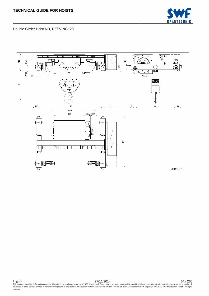
23 DOUBLE GIRDER HOIST ND, REEVING: 28
Hoist dimensions HOL Length H1 M1 M2 BRA Min R Weight
m code mm mm mm mm mm kg
4.5 F 883 828 469 - 1700 840
6 G 883 1018 374 - 1700 870
8 H 1033 1268 399 128 2000 945
11.5 J 1233 1618 424 128 2400 1030
Motor dimensions
Motor P5 P6 P7 A5 S5 S7 MOT (mm) 578 578 618 498 606 757
Weight (kg) 58 85 105 45 53 81
Trolley dimensions
C ∅∅∅∅BU BU BUH E1 E2 E3 GEA WB ∅∅∅∅WD W min W max 785 63 163 100 382 1343 18 143 1080 140 54 84
RO TD TH
98 94 430
D007174_A 124135
Note: All dimensions in mm. Note: Weight calculated with P5 motor. Note: Min R with service platform and second brake. Note: Standard rail gauges: 1700, 2000 and 2400. Note: Gear brake as standard brake for drum lengths H and J. Note: H1, M2 and weight calculated with Min R. Note: Flangeless wheels available.
TECHNICAL GUIDE FOR HOISTS
English 27/11/2014 54 / 266This document and the information contained herein, is the exclusive property of SWF Krantechnik GmbH and represents a non-public, confidential and proprietary trade secret that may not be reproduced,
disclosed to third parties, altered or otherwise employed in any manner whatsoever without the express written consent of SWF Krantechnik GmbH. Copyright © (2013) SWF Krantechnik GmbH. All rights
reserved.
Double Girder Hoist ND, REEVING: 28

TECHNICAL GUIDE FOR HOISTS
English 27/11/2014 55 / 266This document and the information contained herein, is the exclusive property of SWF Krantechnik GmbH and represents a non-public, confidential and proprietary trade secret that may not be reproduced,
disclosed to third parties, altered or otherwise employed in any manner whatsoever without the express written consent of SWF Krantechnik GmbH. Copyright © (2013) SWF Krantechnik GmbH. All rights
reserved.
24 DOUBLE GIRDER HOIST NE, REEVING: 02
Hoist Dimensions HOL HOL* Length M1 M2 H1 H2 Min R Max R Weight**
m m code mm mm mm mm mm mm kg
15.5 10 C 462 714 654 139 1400 1400 1250
21 15.5 D 562 799 739 188 1700 2700 1320
28 22.5 E 682 799 739 251 1700 3100 1370
36 30.5 F 832 949 889 322 2000 3100 1460
47 41.5 G 1022 1149 1089 421 2400 3800 1570
61 55.5 H 1272 1469 1409 546 3100 4200 1750
80.5 75 J 1622 1559 1499 721 3400 4200 1950
97 91.5 K 1922 1944 1884 868 4200 4200 2200
*HOL with drum brake. **Presence of a drum brake will increase weight by 80 kgs.
Motor Dimensions
Motor P6 P7 P8 A7 S7 S8 SA MOT (mm) 536 576 711 536 715 763 803
Weight (kg) 85 105 106 71 81 97 120
Trolley Dimensions
C ∅∅∅∅WD ∅∅∅∅BU BU BUH E1 E2 E3 GEA H3 H4 M3 892 140 63 163 100 488 1842 18 218 757 743 44
RO TD TH WB W min W max 101 90 631 1500 54 84
D006647_A 090649
Note: All dimensions in mm. Note: Weight calculated with P6 motor. Note: Standard rail gauges: 1400, 1700, 2000, 2400, 2700, 3100, 3400, 3800 and 4200. Note: H1, M2 and weight calculated with min R. Note: Flangeless wheels available.

TECHNICAL GUIDE FOR HOISTS
English 27/11/2014 56 / 266This document and the information contained herein, is the exclusive property of SWF Krantechnik GmbH and represents a non-public, confidential and proprietary trade secret that may not be reproduced,
disclosed to third parties, altered or otherwise employed in any manner whatsoever without the express written consent of SWF Krantechnik GmbH. Copyright © (2013) SWF Krantechnik GmbH. All rights
reserved.
Double Girder Hoist NE, REEVING: 02

TECHNICAL GUIDE FOR HOISTS
English 27/11/2014 57 / 266This document and the information contained herein, is the exclusive property of SWF Krantechnik GmbH and represents a non-public, confidential and proprietary trade secret that may not be reproduced,
disclosed to third parties, altered or otherwise employed in any manner whatsoever without the express written consent of SWF Krantechnik GmbH. Copyright © (2013) SWF Krantechnik GmbH. All rights
reserved.
25 DOUBLE GIRDER HOIST NE, REEVING: 04
Hoist Dimensions HOL HOL* Length M1 M2 H1 H2 Min R Max R Weight**
m m code mm mm mm mm mm mm kg
7.5 4.5 C 462 714 654 69 1400 1400 1290
10.5 7.5 D 562 799 739 94 1700 2700 1360
14 11 E 682 799 739 125 1700 3100 1410
18 15 F 832 949 889 161 2000 3100 1500
23.5 20.5 G 1022 1149 1089 210 2400 3800 1620
30.5 27.5 H 1272 1469 1409 273 3100 4200 1790
40 37 J 1622 1559 1499 360 3400 4200 2000
48.5 45.5 K 1922 1944 1884 434 4200 4200 2240
*HOL with drum brake **Presence of a drum brake will increase weight by 80 kgs.
Motor Dimensions
Motor P6 P7 P8 A7 S7 S8 SA MOT (mm) 536 576 711 536 715 763 803
Weight (kg) 85 105 106 71 81 97 120
Trolley Dimensions
C ∅∅∅∅WD ∅∅∅∅BU BU BUH E1 E2 E3 GEA H3 H4 M3 892 140 63 163 100 488 1842 18 218 757 743 44
RO TD TH WB W min W max 101 90 631 1500 54 84
D006648_A 090650
Note: All dimensions in mm. Note: Weight calculated with P6 motor. Note: Standard rail gauges: 1400, 1700, 2000, 2400, 2700, 3100, 3400, 3800 and 4200. Note: H1, M2 and weight calculated with min R. Note: Flangeless wheels available.

TECHNICAL GUIDE FOR HOISTS
English 27/11/2014 58 / 266This document and the information contained herein, is the exclusive property of SWF Krantechnik GmbH and represents a non-public, confidential and proprietary trade secret that may not be reproduced,
disclosed to third parties, altered or otherwise employed in any manner whatsoever without the express written consent of SWF Krantechnik GmbH. Copyright © (2013) SWF Krantechnik GmbH. All rights
reserved.
Double Girder Hoist NE, REEVING: 04

TECHNICAL GUIDE FOR HOISTS
English 27/11/2014 59 / 266This document and the information contained herein, is the exclusive property of SWF Krantechnik GmbH and represents a non-public, confidential and proprietary trade secret that may not be reproduced,
disclosed to third parties, altered or otherwise employed in any manner whatsoever without the express written consent of SWF Krantechnik GmbH. Copyright © (2013) SWF Krantechnik GmbH. All rights
reserved.
26 DOUBLE GIRDER HOIST NE, REEVING: 06
Hoist Dimensions HOL HOL* Length M1 M2 H1 H2 Min R Max R Weight**
m m code mm mm mm mm mm mm kg
5 3 C 462 714 654 46 1400 1400 1570
7 5 D 562 799 739 63 1700 2700 1650
9 7 E 682 799 739 84 1700 3100 1700
12 10 F 832 949 889 107 2000 3100 1800
15.5 13.5 G 1022 1149 1089 140 2400 3800 1940
20 18 H 1272 1469 1409 182 3100 4200 2210
26.5 24.5 J 1622 1559 1499 240 3400 4200 2430
32 30 K 1922 1944 1884 289 4200 4200 2820
*HOL with drum brake **Presence of a drum brake will increase weight by 80 kgs.
Motor Dimensions
Motor P6 P7 P8 A7 S7 S8 SA MOT (mm) 536 576 711 536 715 763 803
Weight (kg) 85 105 106 71 81 97 120
Trolley Dimensions
C ∅∅∅∅WD ∅∅∅∅BU BU BUH E1 E2 E3 GEA H3 H4 M3 949 200 80 226 100 488 1860 80 218 712 698 44
RO TD TH WB W min W max 122 28 693 1410 54 99
D006649_A 090651
Note: All dimensions in mm. Note: Weight calculated with P6 motor. Note: Standard rail gauges: 1400, 1700, 2000, 2400, 2700, 3100, 3400, 3800 and 4200. Note: H1, M2 and weight calculated with min R. Note: Flangeless wheels available.

TECHNICAL GUIDE FOR HOISTS
English 27/11/2014 60 / 266This document and the information contained herein, is the exclusive property of SWF Krantechnik GmbH and represents a non-public, confidential and proprietary trade secret that may not be reproduced,
disclosed to third parties, altered or otherwise employed in any manner whatsoever without the express written consent of SWF Krantechnik GmbH. Copyright © (2013) SWF Krantechnik GmbH. All rights
reserved.
Double Girder Hoist NE, REEVING: 06
TECHNICAL GUIDE FOR HOISTS
English 27/11/2014 61 / 266This document and the information contained herein, is the exclusive property of SWF Krantechnik GmbH and represents a non-public, confidential and proprietary trade secret that may not be reproduced,
disclosed to third parties, altered or otherwise employed in any manner whatsoever without the express written consent of SWF Krantechnik GmbH. Copyright © (2013) SWF Krantechnik GmbH. All rights
reserved.
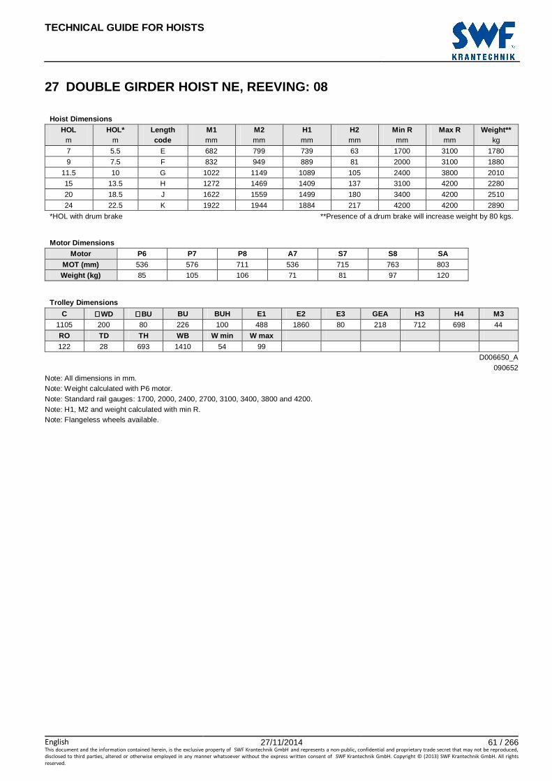
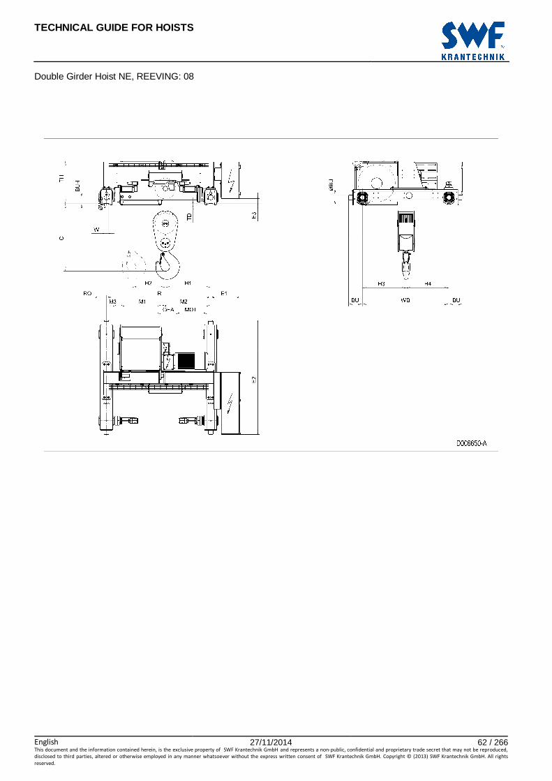
27 DOUBLE GIRDER HOIST NE, REEVING: 08
Hoist Dimensions HOL HOL* Length M1 M2 H1 H2 Min R Max R Weight**
m m code mm mm mm mm mm mm kg
7 5.5 E 682 799 739 63 1700 3100 1780
9 7.5 F 832 949 889 81 2000 3100 1880
11.5 10 G 1022 1149 1089 105 2400 3800 2010
15 13.5 H 1272 1469 1409 137 3100 4200 2280
20 18.5 J 1622 1559 1499 180 3400 4200 2510
24 22.5 K 1922 1944 1884 217 4200 4200 2890
*HOL with drum brake **Presence of a drum brake will increase weight by 80 kgs.
Motor Dimensions
Motor P6 P7 P8 A7 S7 S8 SA MOT (mm) 536 576 711 536 715 763 803
Weight (kg) 85 105 106 71 81 97 120
Trolley Dimensions
C ∅∅∅∅WD ∅∅∅∅BU BU BUH E1 E2 E3 GEA H3 H4 M3 1105 200 80 226 100 488 1860 80 218 712 698 44
RO TD TH WB W min W max 122 28 693 1410 54 99
D006650_A 090652
Note: All dimensions in mm. Note: Weight calculated with P6 motor. Note: Standard rail gauges: 1700, 2000, 2400, 2700, 3100, 3400, 3800 and 4200. Note: H1, M2 and weight calculated with min R. Note: Flangeless wheels available.
TECHNICAL GUIDE FOR HOISTS
English 27/11/2014 62 / 266This document and the information contained herein, is the exclusive property of SWF Krantechnik GmbH and represents a non-public, confidential and proprietary trade secret that may not be reproduced,
disclosed to third parties, altered or otherwise employed in any manner whatsoever without the express written consent of SWF Krantechnik GmbH. Copyright © (2013) SWF Krantechnik GmbH. All rights
reserved.
Double Girder Hoist NE, REEVING: 08

TECHNICAL GUIDE FOR HOISTS
English 27/11/2014 63 / 266This document and the information contained herein, is the exclusive property of SWF Krantechnik GmbH and represents a non-public, confidential and proprietary trade secret that may not be reproduced,
disclosed to third parties, altered or otherwise employed in any manner whatsoever without the express written consent of SWF Krantechnik GmbH. Copyright © (2013) SWF Krantechnik GmbH. All rights
reserved.
28 DOUBLE GIRDER HOIST NE, REEVING: 22
Hoist Dimensions HOL HOL* Length M1 M2 Min R Max R Weight**
m m code mm mm mm mm kg
16.5 9 E 682 359 1400 2000 1310
22 14.5 F 832 434 1700 2400 1380
29.5 22 G 1022 339 1700 2700 1440
39 31.5 H 1272 364 2000 3100 1560
52 44.5 J 1622 389 2400 3400 1720
63.5 56 K 1922 389 2700 3400 1890
77 69.5 L 2272 414 3100 3400 2090
86.5 79 M 2522 439 3400 3800 2240
98 90.5 N 2822 489 3800 4200 2430
*HOL with drum brake **Presence of a drum brake will increase weight by 80 kgs.
Motor Dimensions
Motor P6 P7 P8 A7 S7 S8 SA MOT (mm) 536 576 711 536 715 763 803
Weight (kg) 85 105 106 71 81 97 120
Trolley Dimensions
C ∅∅∅∅WD ∅∅∅∅BU BU BUH E1 E2 E3 GEA H3 H4 M3 807 140 63 163 100 488 1834 18 218 757 743 44
RO TD TH WB W min W max 101 90 631 1500 54 84
D006651_A 090653
Note: All dimensions in mm. Note: Weight calculated with P6 motor. Note: Standard rail gauges: 1400, 1700, 2000, 2400, 2700, 3100, 3400, 3800 and 4200. Note: M2 and weight calculated with min R. Note: Flangeless wheels available.

TECHNICAL GUIDE FOR HOISTS
English 27/11/2014 64 / 266This document and the information contained herein, is the exclusive property of SWF Krantechnik GmbH and represents a non-public, confidential and proprietary trade secret that may not be reproduced,
disclosed to third parties, altered or otherwise employed in any manner whatsoever without the express written consent of SWF Krantechnik GmbH. Copyright © (2013) SWF Krantechnik GmbH. All rights
reserved.
Double Girder Hoist NE, REEVING: 22

TECHNICAL GUIDE FOR HOISTS
English 27/11/2014 65 / 266This document and the information contained herein, is the exclusive property of SWF Krantechnik GmbH and represents a non-public, confidential and proprietary trade secret that may not be reproduced,
disclosed to third parties, altered or otherwise employed in any manner whatsoever without the express written consent of SWF Krantechnik GmbH. Copyright © (2013) SWF Krantechnik GmbH. All rights
reserved.
29 DOUBLE GIRDER HOIST NE, REEVING: 24
Hoist Dimensions HOL HOL* Length M1 M2 Min R Max R Weight**
m m code mm mm mm mm kg
8 4 E 682 359 1400 2000 1380
11 7 F 832 434 1700 2400 1450
14.5 10.5 G 1022 339 1700 2700 1520
19.5 15.5 H 1272 364 2000 3100 1640
26 22 J 1622 389 2400 3400 1800
31.5 27.5 K 1922 389 2700 3800 1970
38.5 34.5 L 2272 414 3100 4200 2170
43 39 M 2522 439 3400 4200 2320
49 45 N 2822 489 3800 4200 2510
*HOL with drum brake **Presence of a drum brake will increase weight by 80 kgs.
Motor Dimensions
Motor P6 P7 P8 A7 S7 S8 SA MOT (mm) 536 576 711 536 715 763 803
Weight (kg) 85 105 106 71 81 97 120
Trolley Dimensions
C ∅∅∅∅WD ∅∅∅∅BU BU BUH E1 E2 E3 GEA H3 H4 M3 1115 140 63 163 100 488 1834 18 218 757 743 44
RO TD TH WB W min W max 101 90 631 1500 54 84
D006652_A 090654
Note: All dimensions in mm. Note: Weight calculated with P6 motor. Note: Standard rail gauges: 1400, 1700, 2000, 2400, 2700, 3100, 3400, 3800 and 4200. Note: M2 and weight calculated with the Min R. Note: Flangeless wheels available.

TECHNICAL GUIDE FOR HOISTS
English 27/11/2014 66 / 266This document and the information contained herein, is the exclusive property of SWF Krantechnik GmbH and represents a non-public, confidential and proprietary trade secret that may not be reproduced,
disclosed to third parties, altered or otherwise employed in any manner whatsoever without the express written consent of SWF Krantechnik GmbH. Copyright © (2013) SWF Krantechnik GmbH. All rights
reserved.
Double Girder Hoist NE, REEVING: 24

TECHNICAL GUIDE FOR HOISTS
English 27/11/2014 67 / 266This document and the information contained herein, is the exclusive property of SWF Krantechnik GmbH and represents a non-public, confidential and proprietary trade secret that may not be reproduced,
disclosed to third parties, altered or otherwise employed in any manner whatsoever without the express written consent of SWF Krantechnik GmbH. Copyright © (2013) SWF Krantechnik GmbH. All rights
reserved.
30 DOUBLE GIRDER HOIST NE, REEVING: 26
Hoist Dimensions HOL HOL* Length M1 M2 Min R Max R Weight**
m m code mm mm mm mm kg
5.5 3 E 682 359 1400 2000 1650
7 4.5 F 832 434 1700 2400 1730
9.5 7 G 1022 339 1700 2700 1800
13 10.5 H 1272 364 2000 3100 1920
17 14.5 J 1622 389 2400 3400 2100
21 18.5 K 1922 389 2700 3800 2280
25.5 23 L 2272 414 3100 4200 2490
28.5 26 M 2522 439 3400 4200 2660
32.5 30 N 2822 489 3800 4200 2870
*HOL with drum brake **Presence of a drum brake will increase weight by 80 kgs.
Motor Dimensions
Motor P6 P7 P8 A7 S7 S8 SA MOT (mm) 536 576 711 536 715 763 803
Weight (kg) 85 105 106 71 81 97 120
Trolley Dimensions
C ∅∅∅∅WD ∅∅∅∅BU BU BUH E1 E2 E3 GEA H3 H4 M3 1154 200 80 226 100 488 1852 80 218 712 698 44
RO TD TH WB W min W max 122 28 693 1410 54 99
D006653_A 090655
Note: All dimensions in mm. Note: Weight calculated with P6 motor. Note: Standard rail gauges: 1400, 1700, 2000, 2400, 2700, 3100, 3400, 3800 and 4200. Note: M2 and weight calculated wit the Min R. Note: Flangeless wheels available.

TECHNICAL GUIDE FOR HOISTS
English 27/11/2014 68 / 266This document and the information contained herein, is the exclusive property of SWF Krantechnik GmbH and represents a non-public, confidential and proprietary trade secret that may not be reproduced,
disclosed to third parties, altered or otherwise employed in any manner whatsoever without the express written consent of SWF Krantechnik GmbH. Copyright © (2013) SWF Krantechnik GmbH. All rights
reserved.
Double Girder Hoist NE, REEVING: 26

TECHNICAL GUIDE FOR HOISTS
English 27/11/2014 69 / 266This document and the information contained herein, is the exclusive property of SWF Krantechnik GmbH and represents a non-public, confidential and proprietary trade secret that may not be reproduced,
disclosed to third parties, altered or otherwise employed in any manner whatsoever without the express written consent of SWF Krantechnik GmbH. Copyright © (2013) SWF Krantechnik GmbH. All rights
reserved.
31 DOUBLE GIRDER HOIST NE, REEVING: 28
Hoist Dimensions HOL HOL* Length M1 M2 Min R Max R Weight**
m m code mm mm mm mm kg
5.5 3.5 F 832 434 1700 2400 1850
7 5 G 1022 339 1700 2700 1920
9.5 7.5 H 1272 364 2000 3100 2050
13 11 J 1622 389 2400 3400 2230
15.5 13.5 K 1922 389 2700 3800 2400
19 17 L 2272 414 3100 4200 2620
21.5 19.5 M 2522 439 3400 4200 2790
24.5 22.5 N 2822 489 3800 4200 3010
*HOL with drum brake **Presence of a drum brake will increase weight by 80 kgs.
Motor Dimensions
Motor P6 P7 P8 A7 S7 S8 SA MOT (mm) 536 576 711 536 715 763 803
Weight (kg) 85 105 106 71 81 97 120
Trolley Dimensions
C ∅∅∅∅WD ∅∅∅∅BU BU BUH E1 E2 E3 GEA H3 H4 M3 1280 200 80 226 100 488 1852 80 218 712 698 44
RO TD TH WB W min W max 122 28 693 1410 54 99
D006654_A 090656
Note: All dimensions in mm. Note: Weight calculated with P6 motor. Note: Standard rail gauges: 1700, 2000, 2400, 2700, 3100, 3400, 3800 and 4200. Note: M2 and weight calculated with the Min R. Note: Flangeless wheels available.

TECHNICAL GUIDE FOR HOISTS
English 27/11/2014 70 / 266This document and the information contained herein, is the exclusive property of SWF Krantechnik GmbH and represents a non-public, confidential and proprietary trade secret that may not be reproduced,
disclosed to third parties, altered or otherwise employed in any manner whatsoever without the express written consent of SWF Krantechnik GmbH. Copyright © (2013) SWF Krantechnik GmbH. All rights
reserved.
Double Girder Hoist NE, REEVING: 28

TECHNICAL GUIDE FOR HOISTS
English 27/11/2014 71 / 266This document and the information contained herein, is the exclusive property of SWF Krantechnik GmbH and represents a non-public, confidential and proprietary trade secret that may not be reproduced,
disclosed to third parties, altered or otherwise employed in any manner whatsoever without the express written consent of SWF Krantechnik GmbH. Copyright © (2013) SWF Krantechnik GmbH. All rights
reserved.
32 DOUBLE GIRDER HOIST NF, REEVING: 22
Hoist Dimensions HOL HOL* Length M1 M2 Min R Max R Weight**
m m code mm mm mm mm kg
15.5 9 F 832 434 1700 2400 1800
20.5 14 G 1022 339 1700 2700 1950
27.5 21 H 1272 214 2000 3100 2080
37.5 31 J 1622 389 2400 3400 2270
46 39.5 K 1922 389 2700 3800 2430
55.5 49 L 2272 414 3100 4200 2620
62.5 56 M 2522 439 3400 4200 2780
71 64.5 N 2822 489 3800 4200 2970
*HOL with drum brake **Presence of a drum brake will increase weight by 80 kgs.
Motor Dimensions
Motor P6 P7 A7 S7 S8 SA MOT (mm) 536 576 536 715 763 803
Weight (kg) 85 105 71 81 97 120
Trolley Dimensions
C ∅∅∅∅WD ∅∅∅∅BU BU BUH E1 E2 E3 GEA H3 H4 M3 960 200 80 226 100 488 1826 80 218 712 698 44
RO TD TH WB W min W max 122 30 693 1410 54 99
D006655_A 090657
Note: All dimensions in mm. Note: Weight calculated with P6 motor. Note: Standard rail gauges: 1700, 2000, 2400, 2700, 3100, 3400, 3800 and 4200. Note: M2 and weight calculated with min R. Note: Flangeless wheels available.
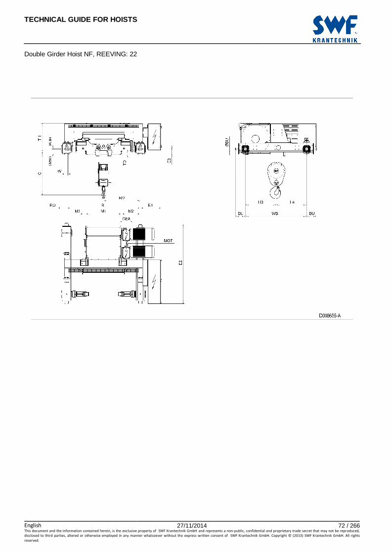
TECHNICAL GUIDE FOR HOISTS
English 27/11/2014 72 / 266This document and the information contained herein, is the exclusive property of SWF Krantechnik GmbH and represents a non-public, confidential and proprietary trade secret that may not be reproduced,
disclosed to third parties, altered or otherwise employed in any manner whatsoever without the express written consent of SWF Krantechnik GmbH. Copyright © (2013) SWF Krantechnik GmbH. All rights
reserved.
Double Girder Hoist NF, REEVING: 22

TECHNICAL GUIDE FOR HOISTS
English 27/11/2014 73 / 266This document and the information contained herein, is the exclusive property of SWF Krantechnik GmbH and represents a non-public, confidential and proprietary trade secret that may not be reproduced,
disclosed to third parties, altered or otherwise employed in any manner whatsoever without the express written consent of SWF Krantechnik GmbH. Copyright © (2013) SWF Krantechnik GmbH. All rights
reserved.
33 DOUBLE GIRDER HOIST NF, REEVING: 24
Hoist Dimensions HOL HOL* Length M1 M2 Min R Max R Weight**
m m code mm mm mm mm kg
7.5 4 F 832 434 1700 2400 2040
10 6.5 G 1022 339 1700 2700 2200
13.5 10 H 1272 214 2000 3100 2330
18.5 15 J 1622 389 2400 3400 2530
23 19.5 K 1922 389 2700 3800 2680
27.5 24 L 2272 414 3100 4200 2880
31 27.5 M 2522 439 3400 4200 3030
35.5 32 N 2822 489 3800 4200 3230
*HOL with drum brake **Presence of a drum brake will increase weight by 80 kgs.
Motor Dimensions
Motor P6 P7 A7 S7 S8 SA MOT (mm) 536 576 536 715 763 803
Weight (kg) 85 105 71 81 97 120
Trolley Dimensions
C ∅∅∅∅WD ∅∅∅∅BU BU BUH E1 E2 E3 GEA H3 H4 M3 1305 200 80 226 100 488 1856 80 218 712 698 44
RO TD TH WB W min W max 122 30 693 1410 54 99
D006656_A 090658
Note: All dimensions in mm. Note: Weight calculated with P6 motor. Note: Standard rail gauges: 1700, 2000, 2400, 2700, 3100, 3400, 3800 and 4200. Note: M2 and weight calculated with min R. Note: Flangeless wheels available.

TECHNICAL GUIDE FOR HOISTS
English 27/11/2014 74 / 266This document and the information contained herein, is the exclusive property of SWF Krantechnik GmbH and represents a non-public, confidential and proprietary trade secret that may not be reproduced,
disclosed to third parties, altered or otherwise employed in any manner whatsoever without the express written consent of SWF Krantechnik GmbH. Copyright © (2013) SWF Krantechnik GmbH. All rights
reserved.
Double Girder Hoist NF, REEVING: 24
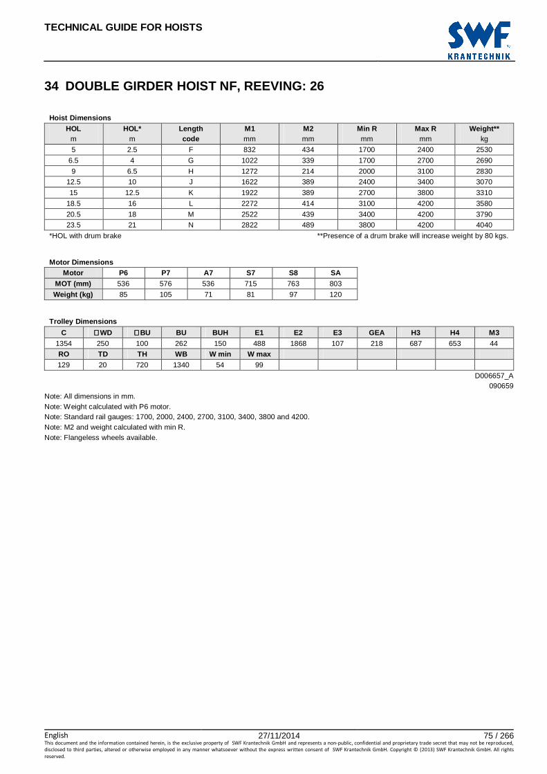
TECHNICAL GUIDE FOR HOISTS
English 27/11/2014 75 / 266This document and the information contained herein, is the exclusive property of SWF Krantechnik GmbH and represents a non-public, confidential and proprietary trade secret that may not be reproduced,
disclosed to third parties, altered or otherwise employed in any manner whatsoever without the express written consent of SWF Krantechnik GmbH. Copyright © (2013) SWF Krantechnik GmbH. All rights
reserved.
34 DOUBLE GIRDER HOIST NF, REEVING: 26
Hoist Dimensions HOL HOL* Length M1 M2 Min R Max R Weight**
m m code mm mm mm mm kg
5 2.5 F 832 434 1700 2400 2530
6.5 4 G 1022 339 1700 2700 2690
9 6.5 H 1272 214 2000 3100 2830
12.5 10 J 1622 389 2400 3400 3070
15 12.5 K 1922 389 2700 3800 3310
18.5 16 L 2272 414 3100 4200 3580
20.5 18 M 2522 439 3400 4200 3790
23.5 21 N 2822 489 3800 4200 4040
*HOL with drum brake **Presence of a drum brake will increase weight by 80 kgs.
Motor Dimensions
Motor P6 P7 A7 S7 S8 SA MOT (mm) 536 576 536 715 763 803
Weight (kg) 85 105 71 81 97 120
Trolley Dimensions
C ∅∅∅∅WD ∅∅∅∅BU BU BUH E1 E2 E3 GEA H3 H4 M3 1354 250 100 262 150 488 1868 107 218 687 653 44
RO TD TH WB W min W max 129 20 720 1340 54 99
D006657_A 090659
Note: All dimensions in mm. Note: Weight calculated with P6 motor. Note: Standard rail gauges: 1700, 2000, 2400, 2700, 3100, 3400, 3800 and 4200. Note: M2 and weight calculated with min R. Note: Flangeless wheels available.
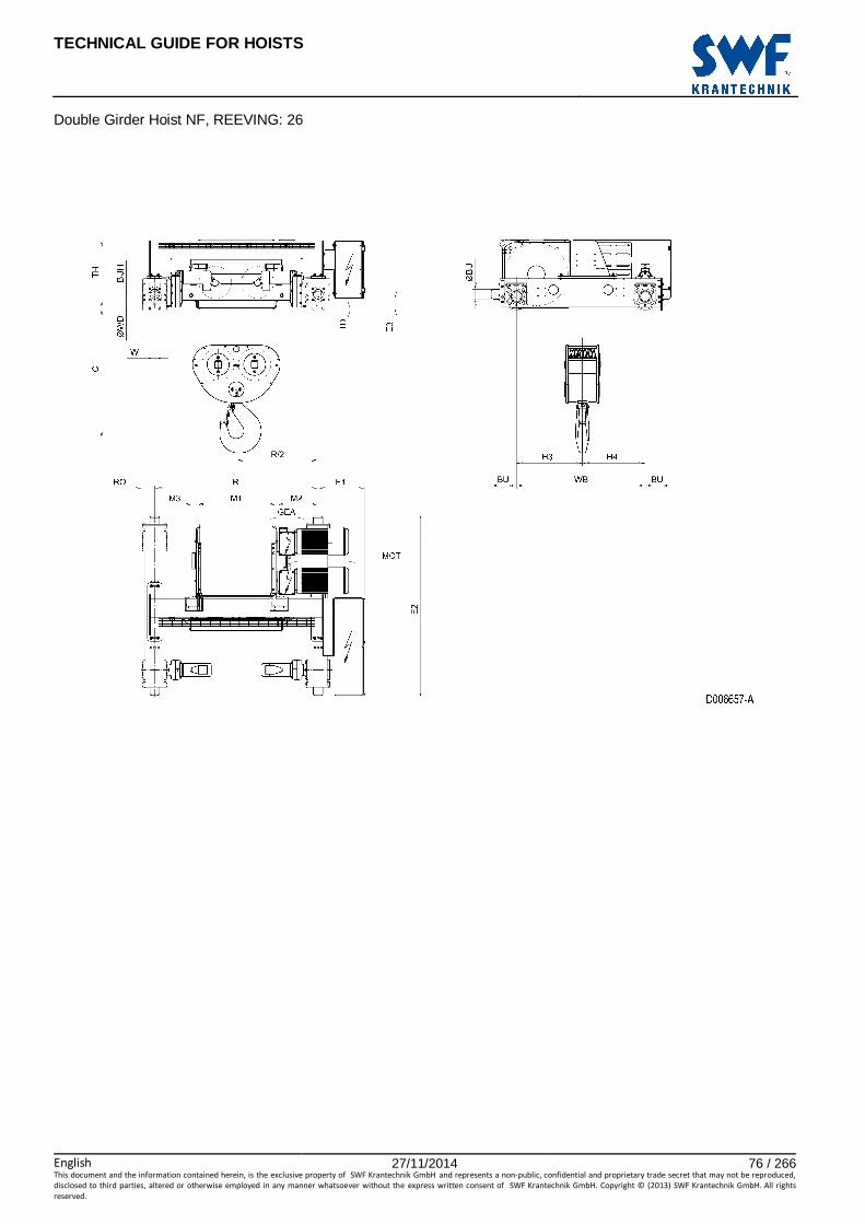
TECHNICAL GUIDE FOR HOISTS
English 27/11/2014 76 / 266This document and the information contained herein, is the exclusive property of SWF Krantechnik GmbH and represents a non-public, confidential and proprietary trade secret that may not be reproduced,
disclosed to third parties, altered or otherwise employed in any manner whatsoever without the express written consent of SWF Krantechnik GmbH. Copyright © (2013) SWF Krantechnik GmbH. All rights
reserved.
Double Girder Hoist NF, REEVING: 26

TECHNICAL GUIDE FOR HOISTS
English 27/11/2014 77 / 266This document and the information contained herein, is the exclusive property of SWF Krantechnik GmbH and represents a non-public, confidential and proprietary trade secret that may not be reproduced,
disclosed to third parties, altered or otherwise employed in any manner whatsoever without the express written consent of SWF Krantechnik GmbH. Copyright © (2013) SWF Krantechnik GmbH. All rights
reserved.
35 DOUBLE GIRDER HOIST NF, REEVING: 28
Hoist Dimensions HOL HOL* Length M1 M2 Min R Max R Weight**
m m code mm mm mm mm kg
6.5 4.5 H 1272 564 2400 3100 3380
9 7 J 1622 389 2400 3400 3610
11 9 K 1922 389 2700 3800 3860
13.5 11.5 L 2272 414 3100 4200 4140
15.5 13.5 M 2522 439 3400 4200 4330
17.5 15.5 N 2822 489 3800 4200 4590
*HOL with drum brake **Presence of a drum brake will increase weight by 80 kgs.
Motor Dimensions
Motor P6 P7 A7 S7 S8 SA MOT (mm) 536 576 536 715 763 803
Weight (kg) 85 105 71 81 97 120
Trolley Dimensions
C ∅∅∅∅WD ∅∅∅∅BU BU BUH E1 E2 E3 GEA H3 H4 M3 1410 250 100 262 150 488 1868 142 218 687 733 44
RO TD TH WB W min W max 173 20 755 1420 54 99
D006658_A 090660
Note: All dimensions in mm. Note: Weight calculated with P6 motor. Note: Standard rail gauges: 2400, 2700, 3100, 3400, 3800 and 4200. Note: M2 and weight calculated with min R. Note: Flangeless wheels available.

TECHNICAL GUIDE FOR HOISTS
English 27/11/2014 78 / 266This document and the information contained herein, is the exclusive property of SWF Krantechnik GmbH and represents a non-public, confidential and proprietary trade secret that may not be reproduced,
disclosed to third parties, altered or otherwise employed in any manner whatsoever without the express written consent of SWF Krantechnik GmbH. Copyright © (2013) SWF Krantechnik GmbH. All rights
reserved.
Double Girder Hoist NF, REEVING: 28
TECHNICAL GUIDE FOR HOISTS
English 27/11/2014 79 / 266This document and the information contained herein, is the exclusive property of SWF Krantechnik GmbH and represents a non-public, confidential and proprietary trade secret that may not be reproduced,
disclosed to third parties, altered or otherwise employed in any manner whatsoever without the express written consent of SWF Krantechnik GmbH. Copyright © (2013) SWF Krantechnik GmbH. All rights
reserved.
DOUBLE GIRDER TROLLEY, HIGH

TECHNICAL GUIDE FOR HOISTS
English 27/11/2014 80 / 266This document and the information contained herein, is the exclusive property of SWF Krantechnik GmbH and represents a non-public, confidential and proprietary trade secret that may not be reproduced,
disclosed to third parties, altered or otherwise employed in any manner whatsoever without the express written consent of SWF Krantechnik GmbH. Copyright © (2013) SWF Krantechnik GmbH. All rights
reserved.

TECHNICAL GUIDE FOR HOISTS
English 27/11/2014 81 / 266This document and the information contained herein, is the exclusive property of SWF Krantechnik GmbH and represents a non-public, confidential and proprietary trade secret that may not be reproduced,
disclosed to third parties, altered or otherwise employed in any manner whatsoever without the express written consent of SWF Krantechnik GmbH. Copyright © (2013) SWF Krantechnik GmbH. All rights
reserved.
36 HIGH DOUBLE GIRDER HOIST NB, REEVING: 02
Hoist dimensions HOL Length M1 M2 H1 H2 Min R Weight
m code mm mm mm mm mm kg
12 A 326 274 369 90 900 210
19 C 456 274 369 144 900 220
Motor dimensions
Motor P1 P2 P3 A3 S3 MOT (mm) 386 446 476 446 526
Weight (kg) 21 31 35 32 28
Trolley dimensions
C ∅∅∅∅BU BU BUH E1 E2 E3 GEA H3 WB ∅∅∅∅WD W min
185 63 138 90 327 714 15 110 398 820 90 50
W max RO TD TH 70 83 15 403
D002074_A 062128
Note: All dimensions in mm. Note: H1, M2 and weight calculated with P1 motor and Min R. Note: Min R with second brake. Note: Standard rail gauges: 900, 1200, 1400, 1700 and 2000. Note: Flangeless wheels available.
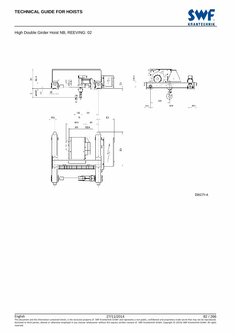
TECHNICAL GUIDE FOR HOISTS
English 27/11/2014 82 / 266This document and the information contained herein, is the exclusive property of SWF Krantechnik GmbH and represents a non-public, confidential and proprietary trade secret that may not be reproduced,
disclosed to third parties, altered or otherwise employed in any manner whatsoever without the express written consent of SWF Krantechnik GmbH. Copyright © (2013) SWF Krantechnik GmbH. All rights
reserved.
High Double Girder Hoist NB, REEVING: 02

TECHNICAL GUIDE FOR HOISTS
English 27/11/2014 83 / 266This document and the information contained herein, is the exclusive property of SWF Krantechnik GmbH and represents a non-public, confidential and proprietary trade secret that may not be reproduced,
disclosed to third parties, altered or otherwise employed in any manner whatsoever without the express written consent of SWF Krantechnik GmbH. Copyright © (2013) SWF Krantechnik GmbH. All rights
reserved.
37 HIGH DOUBLE GIRDER HOIST NB, REEVING: 04
Hoist dimensions HOL Length M1 M2 H1 H2 Min R Weight
m code mm mm mm mm mm kg
6 A 326 274 424 45 900 210
9.5 C 456 274 424 72 900 220
Motor dimensions
Motor P1 P2 P3 A3 S3 MOT (mm) 386 446 476 446 526
Weight (kg) 21 31 35 32 28
Trolley dimensions
C ∅∅∅∅BU BU BUH E1 E2 E3 GEA WB ∅∅∅∅WD W min W max
135 63 138 90 327 714 15 110 820 90 50 70
RO TD TH 83 15 403
D002079_A 028596
Note: All dimensions in mm. Note: H1, M2 and weight calculated with P1 motor and Min R. Note: Min R with second brake. Note: Standard rail gauges: 900, 1200, 1400, 1700 and 2000. Note: Flangeless wheels available.

TECHNICAL GUIDE FOR HOISTS
English 27/11/2014 84 / 266This document and the information contained herein, is the exclusive property of SWF Krantechnik GmbH and represents a non-public, confidential and proprietary trade secret that may not be reproduced,
disclosed to third parties, altered or otherwise employed in any manner whatsoever without the express written consent of SWF Krantechnik GmbH. Copyright © (2013) SWF Krantechnik GmbH. All rights
reserved.
High Double Girder Hoist NB, REEVING: 04
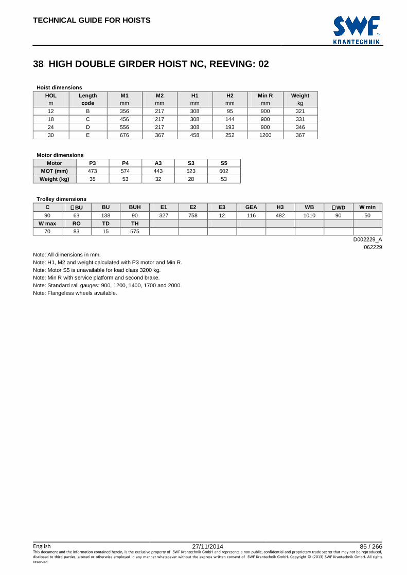
TECHNICAL GUIDE FOR HOISTS
English 27/11/2014 85 / 266This document and the information contained herein, is the exclusive property of SWF Krantechnik GmbH and represents a non-public, confidential and proprietary trade secret that may not be reproduced,
disclosed to third parties, altered or otherwise employed in any manner whatsoever without the express written consent of SWF Krantechnik GmbH. Copyright © (2013) SWF Krantechnik GmbH. All rights
reserved.
38 HIGH DOUBLE GIRDER HOIST NC, REEVING: 02
Hoist dimensions HOL Length M1 M2 H1 H2 Min R Weight
m code mm mm mm mm mm kg
12 B 356 217 308 95 900 321
18 C 456 217 308 144 900 331
24 D 556 217 308 193 900 346
30 E 676 367 458 252 1200 367
Motor dimensions
Motor P3 P4 A3 S3 S5 MOT (mm) 473 574 443 523 602
Weight (kg) 35 53 32 28 53
Trolley dimensions
C ∅∅∅∅BU BU BUH E1 E2 E3 GEA H3 WB ∅∅∅∅WD W min
90 63 138 90 327 758 12 116 482 1010 90 50
W max RO TD TH 70 83 15 575
D002229_A 062229
Note: All dimensions in mm. Note: H1, M2 and weight calculated with P3 motor and Min R. Note: Motor S5 is unavailable for load class 3200 kg. Note: Min R with service platform and second brake. Note: Standard rail gauges: 900, 1200, 1400, 1700 and 2000. Note: Flangeless wheels available.

TECHNICAL GUIDE FOR HOISTS
English 27/11/2014 86 / 266This document and the information contained herein, is the exclusive property of SWF Krantechnik GmbH and represents a non-public, confidential and proprietary trade secret that may not be reproduced,
disclosed to third parties, altered or otherwise employed in any manner whatsoever without the express written consent of SWF Krantechnik GmbH. Copyright © (2013) SWF Krantechnik GmbH. All rights
reserved.
High Double Girder Hoist NC, REEVING: 02

TECHNICAL GUIDE FOR HOISTS
English 27/11/2014 87 / 266This document and the information contained herein, is the exclusive property of SWF Krantechnik GmbH and represents a non-public, confidential and proprietary trade secret that may not be reproduced,
disclosed to third parties, altered or otherwise employed in any manner whatsoever without the express written consent of SWF Krantechnik GmbH. Copyright © (2013) SWF Krantechnik GmbH. All rights
reserved.
39 HIGH DOUBLE GIRDER HOIST NC, REEVING: 04
Hoist dimensions HOL Length M1 M2 H1 H2 Min R Weight
m code mm mm mm mm mm kg
6 B 356 217 386 49 900 325
9 C 456 217 386 74 900 335
12 D 556 217 386 99 900 355
15 E 676 367 536 129 1200 375
Motor dimensions
Motor P3 P4 A3 S3 S5 MOT (mm) 473 574 443 523 602
Weight (kg) 35 53 32 28 53
Trolley dimensions
C1 C2 ∅∅∅∅BU BU BUH E1 E2 E3 GEA WB ∅∅∅∅WD W min
80 97 63 138 90 327 758 12 116 1010 90 50
W max RO TD TH 70 83 15 575
D002230_A 062231
Note: All dimensions in mm. Note: H1, M2 and weight calculated with P3 motor and Min R. Note: Motor S5 is unavailable for load class 6300 kg. Note: Min R with service platform and second brake. Note: Standard rail gauges: 900, 1200, 1400, 1700 and 2000. Note: Flangeless wheels available.

TECHNICAL GUIDE FOR HOISTS
English 27/11/2014 88 / 266This document and the information contained herein, is the exclusive property of SWF Krantechnik GmbH and represents a non-public, confidential and proprietary trade secret that may not be reproduced,
disclosed to third parties, altered or otherwise employed in any manner whatsoever without the express written consent of SWF Krantechnik GmbH. Copyright © (2013) SWF Krantechnik GmbH. All rights
reserved.
High Double Girder Hoist NC, REEVING: 04

TECHNICAL GUIDE FOR HOISTS
English 27/11/2014 89 / 266This document and the information contained herein, is the exclusive property of SWF Krantechnik GmbH and represents a non-public, confidential and proprietary trade secret that may not be reproduced,
disclosed to third parties, altered or otherwise employed in any manner whatsoever without the express written consent of SWF Krantechnik GmbH. Copyright © (2013) SWF Krantechnik GmbH. All rights
reserved.
40 HIGH DOUBLE GIRDER HOIST ND, REEVING: 02
Hoist dimensions HOL Length M1 M2 H1 H2 Min R Weight
m code mm mm mm mm mm kg
18 D 558 303 458 176 1200 665
24 E 678 303 458 235 1200 690
32 F 828 266 421 309 1200 715
40 G 1018 516 671 403 1700 795
Motor dimensions
Motor P5 P6 P7 A5 S5 S7 MOT (mm) 578 578 618 498 606 757
Weight (kg) 58 85 105 45 53 81
Trolley dimensions
C ∅∅∅∅BU BU BUH E1 E2 E3 GEA H3 WB ∅∅∅∅WD W min
211 63 148 100 382 1028 15 143 552 1080 110 52
W max RO TD TH 87 98 15 692
D002238_A 062235
Note: All dimensions in mm. Note: H1, M2 and weight calculated with P5 motor and Min R. Note: Motor S7 is unavailable for load class 6300 kg. Note: Min R with service platform and second brake. Note: Standard rail gauges: 1200, 1400, 1700 and 2000. Note: Flangeless wheels available.

TECHNICAL GUIDE FOR HOISTS
English 27/11/2014 90 / 266This document and the information contained herein, is the exclusive property of SWF Krantechnik GmbH and represents a non-public, confidential and proprietary trade secret that may not be reproduced,
disclosed to third parties, altered or otherwise employed in any manner whatsoever without the express written consent of SWF Krantechnik GmbH. Copyright © (2013) SWF Krantechnik GmbH. All rights
reserved.
High Double Girder Hoist ND, REEVING: 02

TECHNICAL GUIDE FOR HOISTS
English 27/11/2014 91 / 266This document and the information contained herein, is the exclusive property of SWF Krantechnik GmbH and represents a non-public, confidential and proprietary trade secret that may not be reproduced,
disclosed to third parties, altered or otherwise employed in any manner whatsoever without the express written consent of SWF Krantechnik GmbH. Copyright © (2013) SWF Krantechnik GmbH. All rights
reserved.
41 HIGH DOUBLE GIRDER HOIST ND, REEVING: 04
Hoist dimensions HOL Length M1 M2 H1 H2 Min R Weight
m code mm mm mm mm mm kg
9 D 558 303 540 88 1200 685
12 E 678 303 540 118 1200 710
16 F 828 266 503 156 1200 735
20 G 1018 516 753 204 1700 815
Motor dimensions
Motor P5 P6 P7 A5 S5 S7 MOT (mm) 578 578 618 498 606 757
Weight (kg) 58 85 105 45 53 81
Trolley dimensions
C1 C2 ∅∅∅∅BU BU BUH E1 E2 E3 GEA H3 WB ∅∅∅∅WD 155 210 63 148 100 382 1028 15 143 585 1080 110
W min W max RO TD TH 52 87 98 15 692
D002240_A 062246
Note: All dimensions in mm. Note: H1, M2 and weight calculated with P5 motor and Min R. Note: Motor S7 is unavailable for load class 12500 kg. Note: Min R with service platform and second brake. Note: Standard rail gauges: 1200, 1400, 1700 and 2000. Note: Flangeless wheels available.

TECHNICAL GUIDE FOR HOISTS
English 27/11/2014 92 / 266This document and the information contained herein, is the exclusive property of SWF Krantechnik GmbH and represents a non-public, confidential and proprietary trade secret that may not be reproduced,
disclosed to third parties, altered or otherwise employed in any manner whatsoever without the express written consent of SWF Krantechnik GmbH. Copyright © (2013) SWF Krantechnik GmbH. All rights
reserved.
High Double Girder Hoist ND, REEVING: 04

TECHNICAL GUIDE FOR HOISTS
English 27/11/2014 93 / 266This document and the information contained herein, is the exclusive property of SWF Krantechnik GmbH and represents a non-public, confidential and proprietary trade secret that may not be reproduced,
disclosed to third parties, altered or otherwise employed in any manner whatsoever without the express written consent of SWF Krantechnik GmbH. Copyright © (2013) SWF Krantechnik GmbH. All rights
reserved.
42 HIGH DOUBLE GIRDER HOIST ND, REEVING: 06
Hoist dimensions HOL Length M1 M2 H1 H2 Min R Weight
m code mm mm mm mm mm kg
6 D 558 548 515 53 1200 765
8 E 678 628 595 78 1400 800
10 F 828 778 745 98 1700 850
13 G 1018 888 855 132 2000 905
Motor dimensions
Motor P5 P6 P7 A5 S5 S7 MOT (mm) 578 578 618 498 606 757
Weight (kg) 58 85 105 45 53 81
Trolley dimensions
C ∅∅∅∅BU BU BUH E1 E2 E3 GEA WB ∅∅∅∅WD W min W max 525 63 163 100 382 1343 18 143 1080 140 54 84
RO TD TH
98 20 695
D007196_A 124517
Note: All dimensions in mm. Note: H1, M2 and weight calculated with P5 motor and Min R. Note: Min R with service platform and second brake. Note: Standard rail gauges: 1200, 1400, 1700, 2000 and 2400. Note: Flangeless wheels available.

TECHNICAL GUIDE FOR HOISTS
English 27/11/2014 94 / 266This document and the information contained herein, is the exclusive property of SWF Krantechnik GmbH and represents a non-public, confidential and proprietary trade secret that may not be reproduced,
disclosed to third parties, altered or otherwise employed in any manner whatsoever without the express written consent of SWF Krantechnik GmbH. Copyright © (2013) SWF Krantechnik GmbH. All rights
reserved.
High Double Girder Hoist ND, REEVING: 06
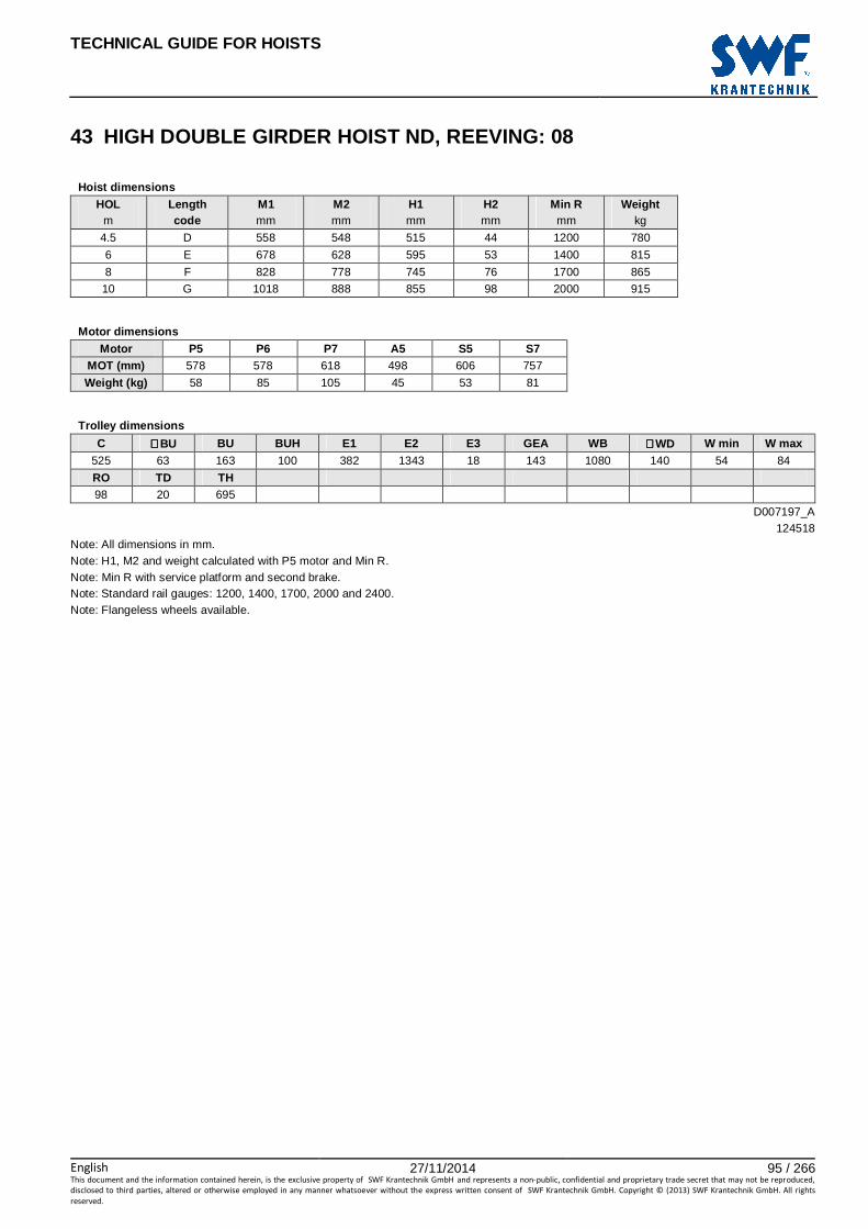
TECHNICAL GUIDE FOR HOISTS
English 27/11/2014 95 / 266This document and the information contained herein, is the exclusive property of SWF Krantechnik GmbH and represents a non-public, confidential and proprietary trade secret that may not be reproduced,
disclosed to third parties, altered or otherwise employed in any manner whatsoever without the express written consent of SWF Krantechnik GmbH. Copyright © (2013) SWF Krantechnik GmbH. All rights
reserved.
43 HIGH DOUBLE GIRDER HOIST ND, REEVING: 08
Hoist dimensions HOL Length M1 M2 H1 H2 Min R Weight
m code mm mm mm mm mm kg
4.5 D 558 548 515 44 1200 780
6 E 678 628 595 53 1400 815
8 F 828 778 745 76 1700 865
10 G 1018 888 855 98 2000 915
Motor dimensions
Motor P5 P6 P7 A5 S5 S7 MOT (mm) 578 578 618 498 606 757
Weight (kg) 58 85 105 45 53 81
Trolley dimensions
C ∅∅∅∅BU BU BUH E1 E2 E3 GEA WB ∅∅∅∅WD W min W max 525 63 163 100 382 1343 18 143 1080 140 54 84
RO TD TH
98 20 695
D007197_A 124518
Note: All dimensions in mm. Note: H1, M2 and weight calculated with P5 motor and Min R. Note: Min R with service platform and second brake. Note: Standard rail gauges: 1200, 1400, 1700, 2000 and 2400. Note: Flangeless wheels available.

TECHNICAL GUIDE FOR HOISTS
English 27/11/2014 96 / 266This document and the information contained herein, is the exclusive property of SWF Krantechnik GmbH and represents a non-public, confidential and proprietary trade secret that may not be reproduced,
disclosed to third parties, altered or otherwise employed in any manner whatsoever without the express written consent of SWF Krantechnik GmbH. Copyright © (2013) SWF Krantechnik GmbH. All rights
reserved.
High Double Girder Hoist ND, REEVING: 08

TECHNICAL GUIDE FOR HOISTS
English 27/11/2014 97 / 266This document and the information contained herein, is the exclusive property of SWF Krantechnik GmbH and represents a non-public, confidential and proprietary trade secret that may not be reproduced,
disclosed to third parties, altered or otherwise employed in any manner whatsoever without the express written consent of SWF Krantechnik GmbH. Copyright © (2013) SWF Krantechnik GmbH. All rights
reserved.
44 HIGH DOUBLE GIRDER HOIST ND, REEVING: 22
Hoist dimensions HOL Length M1 M2 BRA Min R Weight
m code mm mm mm mm kg
8.5 D 558 321 - 1200 675
13 E 678 261 - 1200 695
18 F 828 286 - 1400 735
25 G 1018 341 - 1700 785
33.5 H 1268 216 128 1700 840
46 J 1618 424 128 2400 950
Motor dimensions
Motor P5 P6 P7 A5 S5 S7 MOT (mm) 578 578 618 498 606 757
Weight (kg) 58 85 105 45 53 81
Trolley dimensions
C ∅∅∅∅BU BU BUH E1 E2 E3 GEA H3 WB ∅∅∅∅WD W min 355 63 148 100 382 1328 15 143 585 1080 110 52
W max RO TD TH
87 98 20 692
D007182_A 124426
Note: All dimensions in mm. Note: M2 and weight calculated with P5 motor and Min R. Note: Min R with service platform and second brake. Note: Standard rail gauges: 1200, 1400, 1700, 2000 and 2400. Note: Gear brake as standard brake for drum lengths H and J. Note: Flangeless wheels available.
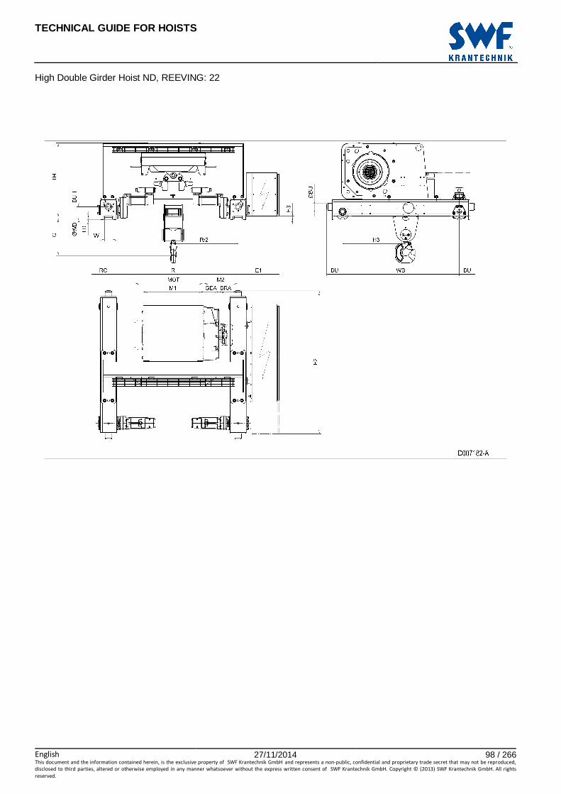
TECHNICAL GUIDE FOR HOISTS
English 27/11/2014 98 / 266This document and the information contained herein, is the exclusive property of SWF Krantechnik GmbH and represents a non-public, confidential and proprietary trade secret that may not be reproduced,
disclosed to third parties, altered or otherwise employed in any manner whatsoever without the express written consent of SWF Krantechnik GmbH. Copyright © (2013) SWF Krantechnik GmbH. All rights
reserved.
High Double Girder Hoist ND, REEVING: 22

TECHNICAL GUIDE FOR HOISTS
English 27/11/2014 99 / 266This document and the information contained herein, is the exclusive property of SWF Krantechnik GmbH and represents a non-public, confidential and proprietary trade secret that may not be reproduced,
disclosed to third parties, altered or otherwise employed in any manner whatsoever without the express written consent of SWF Krantechnik GmbH. Copyright © (2013) SWF Krantechnik GmbH. All rights
reserved.
45 HIGH DOUBLE GIRDER HOIST ND, REEVING: 24
Hoist dimensions HOL Length M1 M2 BRA Min R Weight
m code mm mm mm mm kg
4 D 558 321 - 1200 740
6.5 E 678 261 - 1200 760
9 F 828 286 - 1400 800
12.5 G 1018 341 - 1700 850
16.5 H 1268 216 128 1700 905
23 J 1618 424 128 2400 1015
Motor dimensions
Motor P5 P6 P7 A5 S5 S7 MOT (mm) 578 578 618 498 606 757
Weight (kg) 58 85 105 45 53 81
Trolley dimensions
C ∅∅∅∅BU BU BUH E1 E2 E3 GEA H3 WB ∅∅∅∅WD W min 520 63 148 100 382 1328 15 143 585 1080 110 52
W max RO TD TH
87 98 20 692
D007183_A 124427
Note: All dimensions in mm. Note: M2 and weight calculated with P5 motor and Min R. Note: Min R with service platform and second brake. Note: Standard rail gauges: 1200, 1400, 1700, 2000 and 2400. Note: Gear brake as standard brake for drum lengths H and J. Note: Flangeless wheels available.
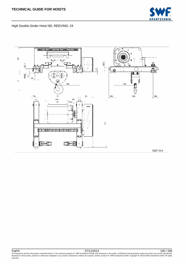
TECHNICAL GUIDE FOR HOISTS
English 27/11/2014 100 / 266This document and the information contained herein, is the exclusive property of SWF Krantechnik GmbH and represents a non-public, confidential and proprietary trade secret that may not be reproduced,
disclosed to third parties, altered or otherwise employed in any manner whatsoever without the express written consent of SWF Krantechnik GmbH. Copyright © (2013) SWF Krantechnik GmbH. All rights
reserved.
High Double Girder Hoist ND, REEVING: 24
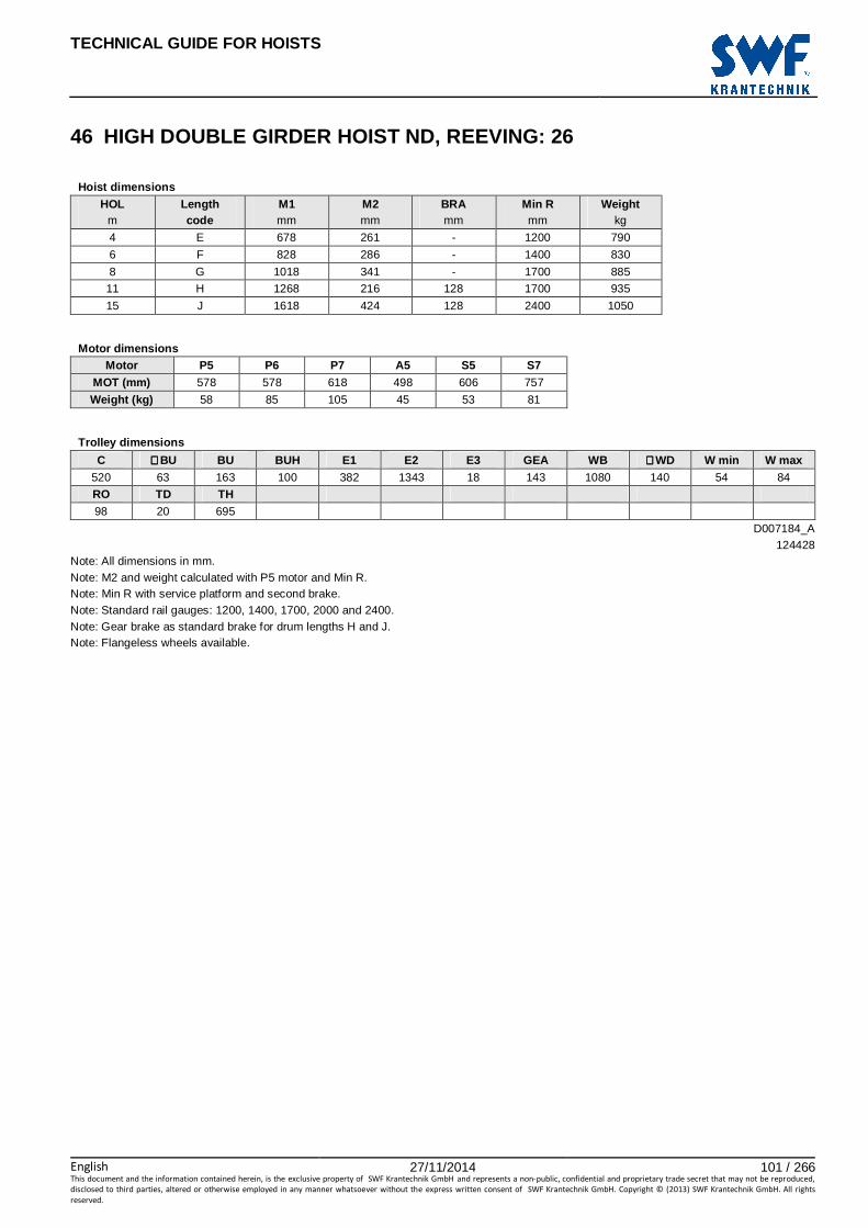
TECHNICAL GUIDE FOR HOISTS
English 27/11/2014 101 / 266This document and the information contained herein, is the exclusive property of SWF Krantechnik GmbH and represents a non-public, confidential and proprietary trade secret that may not be reproduced,
disclosed to third parties, altered or otherwise employed in any manner whatsoever without the express written consent of SWF Krantechnik GmbH. Copyright © (2013) SWF Krantechnik GmbH. All rights
reserved.
46 HIGH DOUBLE GIRDER HOIST ND, REEVING: 26
Hoist dimensions HOL Length M1 M2 BRA Min R Weight
m code mm mm mm mm kg
4 E 678 261 - 1200 790
6 F 828 286 - 1400 830
8 G 1018 341 - 1700 885
11 H 1268 216 128 1700 935
15 J 1618 424 128 2400 1050
Motor dimensions
Motor P5 P6 P7 A5 S5 S7 MOT (mm) 578 578 618 498 606 757
Weight (kg) 58 85 105 45 53 81
Trolley dimensions
C ∅∅∅∅BU BU BUH E1 E2 E3 GEA WB ∅∅∅∅WD W min W max 520 63 163 100 382 1343 18 143 1080 140 54 84
RO TD TH
98 20 695
D007184_A 124428
Note: All dimensions in mm. Note: M2 and weight calculated with P5 motor and Min R. Note: Min R with service platform and second brake. Note: Standard rail gauges: 1200, 1400, 1700, 2000 and 2400. Note: Gear brake as standard brake for drum lengths H and J. Note: Flangeless wheels available.

TECHNICAL GUIDE FOR HOISTS
English 27/11/2014 102 / 266This document and the information contained herein, is the exclusive property of SWF Krantechnik GmbH and represents a non-public, confidential and proprietary trade secret that may not be reproduced,
disclosed to third parties, altered or otherwise employed in any manner whatsoever without the express written consent of SWF Krantechnik GmbH. Copyright © (2013) SWF Krantechnik GmbH. All rights
reserved.
High Double Girder Hoist ND, REEVING: 26

TECHNICAL GUIDE FOR HOISTS
English 27/11/2014 103 / 266This document and the information contained herein, is the exclusive property of SWF Krantechnik GmbH and represents a non-public, confidential and proprietary trade secret that may not be reproduced,
disclosed to third parties, altered or otherwise employed in any manner whatsoever without the express written consent of SWF Krantechnik GmbH. Copyright © (2013) SWF Krantechnik GmbH. All rights
reserved.
47 HIGH DOUBLE GIRDER HOIST ND, REEVING: 28
Hoist dimensions HOL Length M1 M2 BRA Min R Weight
m code mm mm mm mm kg
4.5 F 828 286 - 1400 840
6 G 1018 341 - 1700 895
8 H 1268 216 128 1700 945
11.5 J 1618 424 128 2400 1060
Motor dimensions
Motor P5 P6 P7 A5 S5 S7 MOT (mm) 578 578 618 498 606 757
Weight (kg) 58 85 105 45 53 81
Trolley dimensions
C ∅∅∅∅BU BU BUH E1 E2 E3 GEA WB ∅∅∅∅WD W min W max 520 63 163 100 382 1343 18 143 1080 140 54 84
RO TD TH
98 20 695
D007185_A 124429
Note: All dimensions in mm. Note: M2 and weight calculated with P5 motor and Min R. Note: Min R with service platform and second brake. Note: Standard rail gauges: 1400, 1700, 2000 and 2400. Note: Gear brake as standard brake for drum lengths H and J. Note: Flangeless wheels available.

TECHNICAL GUIDE FOR HOISTS
English 27/11/2014 104 / 266This document and the information contained herein, is the exclusive property of SWF Krantechnik GmbH and represents a non-public, confidential and proprietary trade secret that may not be reproduced,
disclosed to third parties, altered or otherwise employed in any manner whatsoever without the express written consent of SWF Krantechnik GmbH. Copyright © (2013) SWF Krantechnik GmbH. All rights
reserved.
High Double Girder Hoist ND, REEVING: 28

TECHNICAL GUIDE FOR HOISTS
English 27/11/2014 105 / 266This document and the information contained herein, is the exclusive property of SWF Krantechnik GmbH and represents a non-public, confidential and proprietary trade secret that may not be reproduced,
disclosed to third parties, altered or otherwise employed in any manner whatsoever without the express written consent of SWF Krantechnik GmbH. Copyright © (2013) SWF Krantechnik GmbH. All rights
reserved.
DOUBLE GIRDER TROLLEY, LOW

TECHNICAL GUIDE FOR HOISTS
English 27/11/2014 106 / 266This document and the information contained herein, is the exclusive property of SWF Krantechnik GmbH and represents a non-public, confidential and proprietary trade secret that may not be reproduced,
disclosed to third parties, altered or otherwise employed in any manner whatsoever without the express written consent of SWF Krantechnik GmbH. Copyright © (2013) SWF Krantechnik GmbH. All rights
reserved.
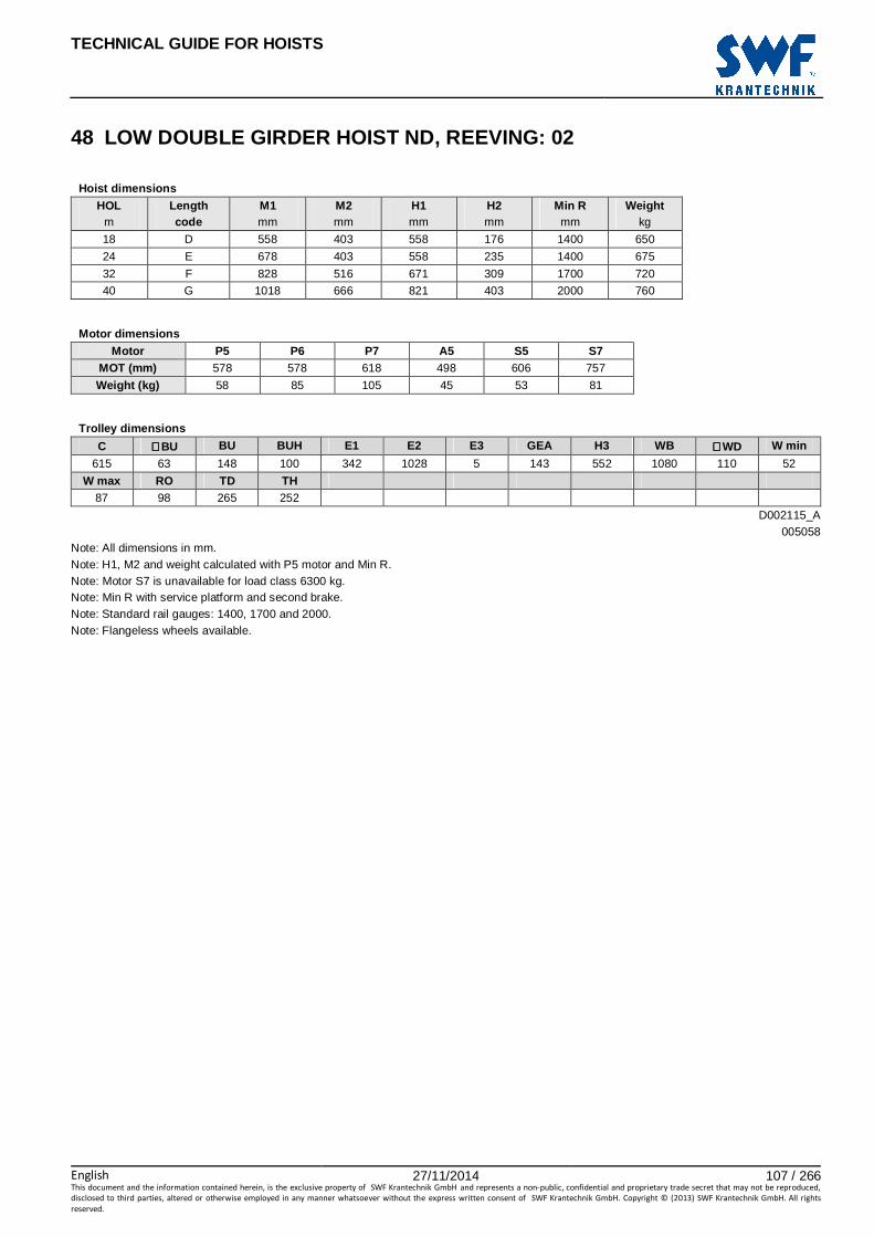
TECHNICAL GUIDE FOR HOISTS
English 27/11/2014 107 / 266This document and the information contained herein, is the exclusive property of SWF Krantechnik GmbH and represents a non-public, confidential and proprietary trade secret that may not be reproduced,
disclosed to third parties, altered or otherwise employed in any manner whatsoever without the express written consent of SWF Krantechnik GmbH. Copyright © (2013) SWF Krantechnik GmbH. All rights
reserved.
48 LOW DOUBLE GIRDER HOIST ND, REEVING: 02
Hoist dimensions HOL Length M1 M2 H1 H2 Min R Weight
m code mm mm mm mm mm kg
18 D 558 403 558 176 1400 650
24 E 678 403 558 235 1400 675
32 F 828 516 671 309 1700 720
40 G 1018 666 821 403 2000 760
Motor dimensions
Motor P5 P6 P7 A5 S5 S7 MOT (mm) 578 578 618 498 606 757
Weight (kg) 58 85 105 45 53 81
Trolley dimensions
C ∅∅∅∅BU BU BUH E1 E2 E3 GEA H3 WB ∅∅∅∅WD W min
615 63 148 100 342 1028 5 143 552 1080 110 52
W max RO TD TH 87 98 265 252
D002115_A 005058
Note: All dimensions in mm. Note: H1, M2 and weight calculated with P5 motor and Min R. Note: Motor S7 is unavailable for load class 6300 kg. Note: Min R with service platform and second brake. Note: Standard rail gauges: 1400, 1700 and 2000. Note: Flangeless wheels available.

TECHNICAL GUIDE FOR HOISTS
English 27/11/2014 108 / 266This document and the information contained herein, is the exclusive property of SWF Krantechnik GmbH and represents a non-public, confidential and proprietary trade secret that may not be reproduced,
disclosed to third parties, altered or otherwise employed in any manner whatsoever without the express written consent of SWF Krantechnik GmbH. Copyright © (2013) SWF Krantechnik GmbH. All rights
reserved.
Low Double Girder Hoist ND, REEVING: 02

TECHNICAL GUIDE FOR HOISTS
English 27/11/2014 109 / 266This document and the information contained herein, is the exclusive property of SWF Krantechnik GmbH and represents a non-public, confidential and proprietary trade secret that may not be reproduced,
disclosed to third parties, altered or otherwise employed in any manner whatsoever without the express written consent of SWF Krantechnik GmbH. Copyright © (2013) SWF Krantechnik GmbH. All rights
reserved.
49 LOW DOUBLE GIRDER HOIST ND, REEVING: 04
Hoist dimensions HOL Length M1 M2 H1 H2 Min R Weight
m code mm mm mm mm mm kg
9 D 558 403 640 88 1400 670
12 E 678 403 640 118 1400 700
16 F 828 516 753 156 1700 745
20 G 1018 666 903 204 2000 785
Motor dimensions
Motor P5 P6 P7 A5 S5 S7 MOT (mm) 578 578 618 498 606 757
Weight (kg) 58 85 105 45 53 81
Trolley dimensions
C1 C2 ∅∅∅∅BU BU BUH E1 E2 E3 GEA H3 WB ∅∅∅∅WD 595 651 63 148 100 342 1028 5 143 585 1080 110
W min W max RO TD TH 52 87 98 265 252
D002122_A 005060
Note: All dimensions in mm. Note: H1, M2 and weight calculated with P5 motor and Min R. Note: Motor S7 is unavailable for load class 12500 kg. Note: Min R with service platform and second brake. Note: Standard rail gauges: 1400, 1700 and 2000. Note: Flangeless wheels available.
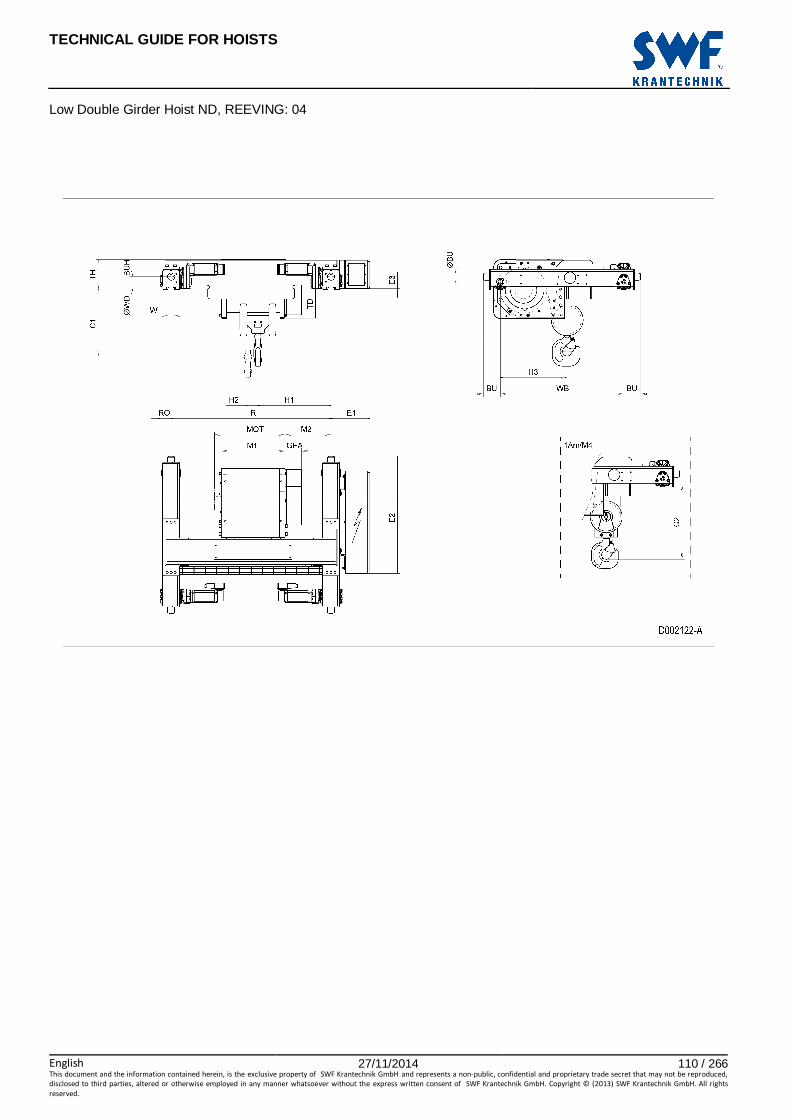
TECHNICAL GUIDE FOR HOISTS
English 27/11/2014 110 / 266This document and the information contained herein, is the exclusive property of SWF Krantechnik GmbH and represents a non-public, confidential and proprietary trade secret that may not be reproduced,
disclosed to third parties, altered or otherwise employed in any manner whatsoever without the express written consent of SWF Krantechnik GmbH. Copyright © (2013) SWF Krantechnik GmbH. All rights
reserved.
Low Double Girder Hoist ND, REEVING: 04

TECHNICAL GUIDE FOR HOISTS
English 27/11/2014 111 / 266This document and the information contained herein, is the exclusive property of SWF Krantechnik GmbH and represents a non-public, confidential and proprietary trade secret that may not be reproduced,
disclosed to third parties, altered or otherwise employed in any manner whatsoever without the express written consent of SWF Krantechnik GmbH. Copyright © (2013) SWF Krantechnik GmbH. All rights
reserved.
NORMAL HEADROOM TROLLEY

TECHNICAL GUIDE FOR HOISTS
English 27/11/2014 112 / 266This document and the information contained herein, is the exclusive property of SWF Krantechnik GmbH and represents a non-public, confidential and proprietary trade secret that may not be reproduced,
disclosed to third parties, altered or otherwise employed in any manner whatsoever without the express written consent of SWF Krantechnik GmbH. Copyright © (2013) SWF Krantechnik GmbH. All rights
reserved.

TECHNICAL GUIDE FOR HOISTS
English 27/11/2014 113 / 266This document and the information contained herein, is the exclusive property of SWF Krantechnik GmbH and represents a non-public, confidential and proprietary trade secret that may not be reproduced,
disclosed to third parties, altered or otherwise employed in any manner whatsoever without the express written consent of SWF Krantechnik GmbH. Copyright © (2013) SWF Krantechnik GmbH. All rights
reserved.
50 NORMAL HEADROOM HOIST NB, REEVING: 02
Hoist dimensions HOL Length M1 H1 H2 H3 H3* H4 BF Weight
m code mm mm mm mm mm mm mm kg
12 A 326 190 90 447 462 633 58 250
19 C 456 190 144 447 462 633 58 270
Motor dimensions Travelling dimensions
Motor P1 P2 P3 A3 S3 Motor MF06LA MOT (mm) 386 446 476 446 526 TMO (mm) 400
Weight (kg) 21 31 35 32 28 Weight (kg) 7.8
Trolley dimensions B min. B max. C ∅∅∅∅BU ∅∅∅∅WD BU BUF BUH E1 E2 GEA M2
100 450 740 63 100 253 412 40 241 372 110 96
TF TD TH TW 45 557 150 31
D002077_A 062129
Minimum track radius B Min R
100 - 109 2500
110 - 119 2000
120 - 450 1500
Note: All dimensions in mm. Note: Weight calculated with P1 motor when B=300 mm. Note: Additional travelling machinery for curved track (option) indicated with an ‘X’ in the drawing. * Please, disregard the dimension H3*.

TECHNICAL GUIDE FOR HOISTS
English 27/11/2014 114 / 266This document and the information contained herein, is the exclusive property of SWF Krantechnik GmbH and represents a non-public, confidential and proprietary trade secret that may not be reproduced,
disclosed to third parties, altered or otherwise employed in any manner whatsoever without the express written consent of SWF Krantechnik GmbH. Copyright © (2013) SWF Krantechnik GmbH. All rights
reserved.
Normal Headroom Hoist NB, REEVING: 02

TECHNICAL GUIDE FOR HOISTS
English 27/11/2014 115 / 266This document and the information contained herein, is the exclusive property of SWF Krantechnik GmbH and represents a non-public, confidential and proprietary trade secret that may not be reproduced,
disclosed to third parties, altered or otherwise employed in any manner whatsoever without the express written consent of SWF Krantechnik GmbH. Copyright © (2013) SWF Krantechnik GmbH. All rights
reserved.
51 NORMAL HEADROOM HOIST NB, REEVING: 04
Hoist dimensions HOL Length M1 H1 H2 H3 H3* H4 BF Weight
m code mm mm mm mm mm mm mm kg
6 A 326 238 45 465 480 617 58 260
9.5 C 456 238 72 465 480 617 58 300
Motor dimensions Travelling dimensions
Motor P1 P2 P3 A3 S3 Motor MF06LA MOT (mm) 386 446 476 446 526 TMO (mm) 400
Weight (kg) 21 31 35 32 28 Weight (kg) 7.8
Trolley dimensions B min. B max. C ∅∅∅∅BU ∅∅∅∅WD BU BUF BUH E1 E2 GEA M2
80 450 690 63 100 253 412 40 296 317 110 151
TF TD TH TW 45 557 150 31
D002082_A 062130
Minimum track radius B Min R
100 - 109 2500
110 - 119 2000
120 - 450 1500
Note: All dimensions in mm. Note: Weight calculated with P1 motor,when B=300 mm. Note: Additional travelling machinery for curved track (option) indicated with an ‘X’ in the drawing. * Please, disregard the dimension H3*.

TECHNICAL GUIDE FOR HOISTS
English 27/11/2014 116 / 266This document and the information contained herein, is the exclusive property of SWF Krantechnik GmbH and represents a non-public, confidential and proprietary trade secret that may not be reproduced,
disclosed to third parties, altered or otherwise employed in any manner whatsoever without the express written consent of SWF Krantechnik GmbH. Copyright © (2013) SWF Krantechnik GmbH. All rights
reserved.
Normal Headroom Hoist NB, REEVING: 04

TECHNICAL GUIDE FOR HOISTS
English 27/11/2014 117 / 266This document and the information contained herein, is the exclusive property of SWF Krantechnik GmbH and represents a non-public, confidential and proprietary trade secret that may not be reproduced,
disclosed to third parties, altered or otherwise employed in any manner whatsoever without the express written consent of SWF Krantechnik GmbH. Copyright © (2013) SWF Krantechnik GmbH. All rights
reserved.
52 NORMAL HEADROOM HOIST NC, REEVING: 02
Hoist dimensions HOL Length BU BUF BF M1 H1 H2 H3 H3* H4 Weight
m code mm mm mm mm mm mm mm mm mm kg
12 B 373 586 269 356 244 98 532 548 665 350
18 C 373 586 269 456 244 147 532 548 665 390
24 D 373 586 373 556 244 198 532 548 665 420
30 E 253 737 218 676 274 258 532 548 665 480
Motor dimensions Travelling dimensions
Motor P3 P4 A3 S3 S5 Motor MF06LA MOT (mm) 473 574 443 523 602 TMO (mm) 400
Weight (kg) 35 53 32 28 53 Weight (kg) 7.8
Trolley dimensions
B min B max C ∅∅∅∅BU ∅∅∅∅WD BUH GEA M2 TD TF TH TS
120 450 835 63 100 40 116 87 586 40 150 420
TW 31
Trolley dimensions Length E1 E2 code
B/C/D 233 505
E 199 540
D002090_A
062140 Note: All dimensions in mm. Note: Weight calculated with P3 motor, when B=300 mm. Note: Motor S5 is unavailable for load class 3200 kg. * Please, disregard the dimension H3*.
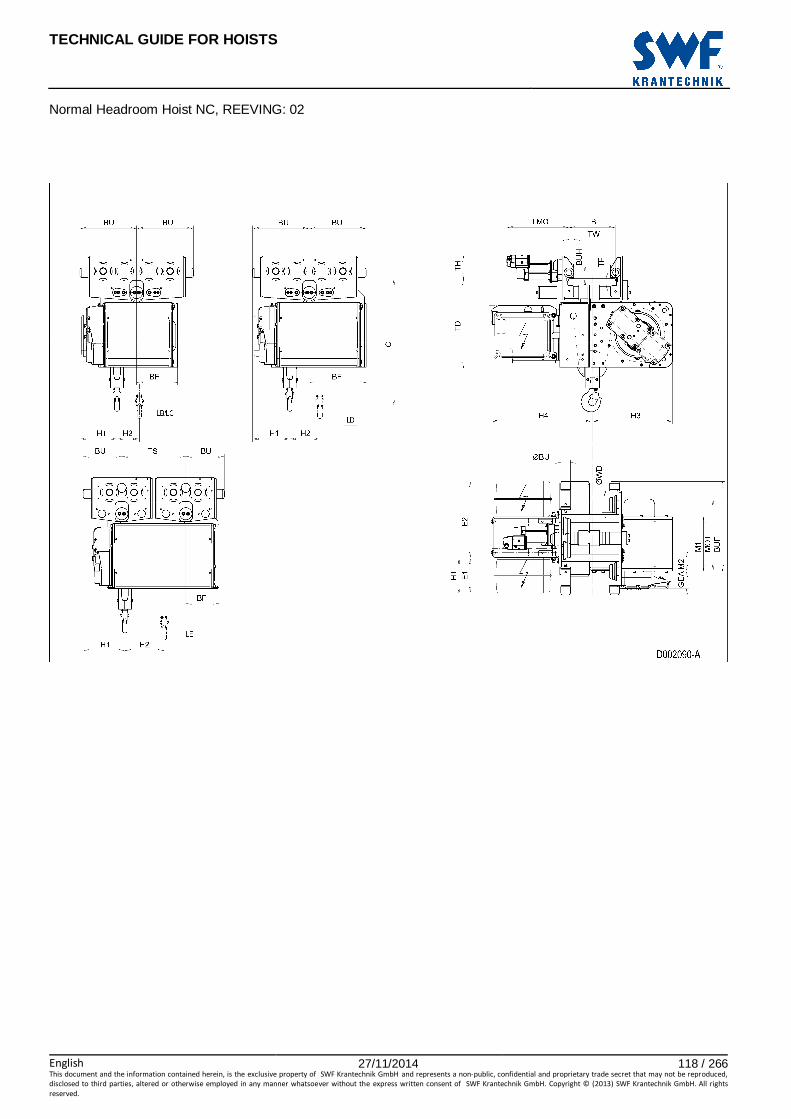
TECHNICAL GUIDE FOR HOISTS
English 27/11/2014 118 / 266This document and the information contained herein, is the exclusive property of SWF Krantechnik GmbH and represents a non-public, confidential and proprietary trade secret that may not be reproduced,
disclosed to third parties, altered or otherwise employed in any manner whatsoever without the express written consent of SWF Krantechnik GmbH. Copyright © (2013) SWF Krantechnik GmbH. All rights
reserved.
Normal Headroom Hoist NC, REEVING: 02

TECHNICAL GUIDE FOR HOISTS
English 27/11/2014 119 / 266This document and the information contained herein, is the exclusive property of SWF Krantechnik GmbH and represents a non-public, confidential and proprietary trade secret that may not be reproduced,
disclosed to third parties, altered or otherwise employed in any manner whatsoever without the express written consent of SWF Krantechnik GmbH. Copyright © (2013) SWF Krantechnik GmbH. All rights
reserved.
53 NORMAL HEADROOM HOIST NC, REEVING: 02, CURVED TR ACK
Hoist dimensions HOL Length M1 H1 H2 H3 H3* H4 Weight
m code mm mm mm mm mm mm kg
12 B 356 350 98 532 548 663 470
18 C 456 350 147 532 548 663 490
24 D 556 350 198 532 548 663 530
30 E 676 350 258 532 548 663 540
Motor dimensions Travelling dimensions
Motor P3 P4 A3 S3 S5 Motor MF06LA MOT (mm) 473 574 443 523 602 TMO (mm) 400
Weight (kg) 35 53 32 28 53 Weight (kg) 7.8
Trolley dimensions
B min B max C ∅∅∅∅BU ∅∅∅∅WD BU BUF BUH GEA M2 TD TF
90 350 995 63 100 253 790 40 116 113 746 42
TH TS TW 150 523 31
D003840_A 062168
Track radius B R min
90 - 109 2500
110 - 119 2000
120 - 350 1500
Note: All dimensions in mm. Note: Weight calculated with P3 motor. Note: Motor S5 is unavailable for load class 3200 kg. * Please, disregard the dimension H3*.

TECHNICAL GUIDE FOR HOISTS
English 27/11/2014 120 / 266This document and the information contained herein, is the exclusive property of SWF Krantechnik GmbH and represents a non-public, confidential and proprietary trade secret that may not be reproduced,
disclosed to third parties, altered or otherwise employed in any manner whatsoever without the express written consent of SWF Krantechnik GmbH. Copyright © (2013) SWF Krantechnik GmbH. All rights
reserved.
Normal Headroom Hoist NC, REEVING: 02, Curved Track

TECHNICAL GUIDE FOR HOISTS
English 27/11/2014 121 / 266This document and the information contained herein, is the exclusive property of SWF Krantechnik GmbH and represents a non-public, confidential and proprietary trade secret that may not be reproduced,
disclosed to third parties, altered or otherwise employed in any manner whatsoever without the express written consent of SWF Krantechnik GmbH. Copyright © (2013) SWF Krantechnik GmbH. All rights
reserved.
54 NORMAL HEADROOM HOIST NC, REEVING: 04
Hoist dimensions HOL Length BU BUF BF M1 H1 H2 H3 H3* H4 Weight
m code mm mm mm mm mm mm mm mm mm kg
6 B 253 466 269 356 205 49 555 571 638 470
9 C 253 466 269 456 205 73 555 571 638 490
12 D 373 586 373 556 325 97 555 571 638 530
15 E 253 737 218 676 354 121 555 571 638 540
Motor dimensions Travelling dimensions
Motor P3 P4 A3 S3 S5 Motor MF06LA MOT (mm) 473 574 443 523 602 TMO (mm) 400
Weight (kg) 35 53 32 28 53 Weight (kg) 7.8
Trolley dimensions
B min B max C ∅∅∅∅BU ∅∅∅∅WD BUH GEA M2 TD TF TH TS
80 450 870 63 100 40 116 168 586 40 150 420
TW 31
Trolley dimensions Length E1 E2 code
B/C/D 313 425
E 284 454
D002097_A 062143
Note: All dimensions in mm. Note: Weight calculated with P3 motor, when B=300 mm. Note: Motor S5 is unavailable for load class 6300 kg. * Please, disregard the dimension H3*.

TECHNICAL GUIDE FOR HOISTS
English 27/11/2014 122 / 266This document and the information contained herein, is the exclusive property of SWF Krantechnik GmbH and represents a non-public, confidential and proprietary trade secret that may not be reproduced,
disclosed to third parties, altered or otherwise employed in any manner whatsoever without the express written consent of SWF Krantechnik GmbH. Copyright © (2013) SWF Krantechnik GmbH. All rights
reserved.
Normal Headroom Hoist NC, REEVING: 04

TECHNICAL GUIDE FOR HOISTS
English 27/11/2014 123 / 266This document and the information contained herein, is the exclusive property of SWF Krantechnik GmbH and represents a non-public, confidential and proprietary trade secret that may not be reproduced,
disclosed to third parties, altered or otherwise employed in any manner whatsoever without the express written consent of SWF Krantechnik GmbH. Copyright © (2013) SWF Krantechnik GmbH. All rights
reserved.
55 NORMAL HEADROOM HOIST NC, REEVING: 04, CURVED TR ACK
Hoist dimensions HOL Length M1 M2 H1 H2 H3 H3* H4 Weight
m code mm mm mm mm mm mm mm kg
6 B 356 165 205 49 555 571 638 360
9 C 456 165 205 73 555 571 638 400
12 D 556 193 430 97 555 571 638 550
15 E 676 193 430 121 555 571 638 565
Motor dimensions Travelling dimensions
Motor P3 P4 A3 S3 S5 Motor MF06LA MOT (mm) 473 574 443 523 602 TMO (mm) 400
Weight (kg) 35 53 32 28 53 Weight (kg) 7.8
Trolley dimensions B1 min B1 max B2 min B2 max C1 C2 ∅∅∅∅BU ∅∅∅∅WD BU BUH GEA TH
80 450 90 350 870 1030 63 100 253 40 116 150
TS TW 523 31
Trolley dimensions Length BUF E1 E2 TD TF code
B/C 522 313 425 586 40
D/E 967 357 381 746 42
D003841_A 062169
Track radius B R min
80 - 109 2500
110 - 119 2000
120 - 450 1500
Note: All dimensions in mm. Note: Weight calculated with P3 motor. Note: Motor S5 is unavailable for load class 6300 kg. * Please, disregard the dimension H3*.

TECHNICAL GUIDE FOR HOISTS
English 27/11/2014 124 / 266This document and the information contained herein, is the exclusive property of SWF Krantechnik GmbH and represents a non-public, confidential and proprietary trade secret that may not be reproduced,
disclosed to third parties, altered or otherwise employed in any manner whatsoever without the express written consent of SWF Krantechnik GmbH. Copyright © (2013) SWF Krantechnik GmbH. All rights
reserved.
Normal Headroom Hoist NC, REEVING: 04, Curved Track

TECHNICAL GUIDE FOR HOISTS
English 27/11/2014 125 / 266This document and the information contained herein, is the exclusive property of SWF Krantechnik GmbH and represents a non-public, confidential and proprietary trade secret that may not be reproduced,
disclosed to third parties, altered or otherwise employed in any manner whatsoever without the express written consent of SWF Krantechnik GmbH. Copyright © (2013) SWF Krantechnik GmbH. All rights
reserved.
56 NORMAL HEADROOM HOIST ND, REEVING: 02
Hoist dimensions HOL Length M1 H1 H2 H3 H3* H4 Weight
m code mm mm mm mm mm mm kg
18 D 558 361 176 625 645 667 750
24 E 678 361 235 625 645 667 820
32 F 828 336 309 625 645 667 900
40 G 1018 336 403 625 645 667 960
Motor dimensions Travelling dimensions
Motor P5 P6 P7 A5 S5 S7 Motor MF06MA MF06LA MOT (mm) 578 578 618 498 606 757 TMO (mm) 360 400
Weight (kg) 58 85 105 45 53 81 Weight (kg) 5.7 7.8
Trolley dimensions
B min B max C ∅∅∅∅BU ∅∅∅∅WD BU BUH GEA M2 TD TF TH
120 610 1080 63 100 253 40 143 158 700 40 150
TW 31
D002114_A 062272
Trolley dimensions Length TS BUF code
D/E 494 924
F/G 522 1239
Note: All dimensions in mm. Note: Weight calculated with P6 motor, when B=300 mm. Note: Motor S7 is unavailable for load class 6300 kg. * Please, disregard the dimension H3*.

TECHNICAL GUIDE FOR HOISTS
English 27/11/2014 126 / 266This document and the information contained herein, is the exclusive property of SWF Krantechnik GmbH and represents a non-public, confidential and proprietary trade secret that may not be reproduced,
disclosed to third parties, altered or otherwise employed in any manner whatsoever without the express written consent of SWF Krantechnik GmbH. Copyright © (2013) SWF Krantechnik GmbH. All rights
reserved.
Normal Headroom Hoist ND, REEVING: 02

TECHNICAL GUIDE FOR HOISTS
English 27/11/2014 127 / 266This document and the information contained herein, is the exclusive property of SWF Krantechnik GmbH and represents a non-public, confidential and proprietary trade secret that may not be reproduced,
disclosed to third parties, altered or otherwise employed in any manner whatsoever without the express written consent of SWF Krantechnik GmbH. Copyright © (2013) SWF Krantechnik GmbH. All rights
reserved.
57 NORMAL HEADROOM HOIST ND, REEVING: 02, CURVED TR ACK
Hoist dimensions HOL Length M1 H1 H2 H3 H3* H4 Weight
m code mm mm mm mm mm mm kg
18 D 558 389 176 625 645 667 810
24 E 678 389 235 625 645 667 870
32 F 828 389 309 625 645 667 940
40 G 1018 389 403 625 645 667 1000
Motor dimensions Travelling dimensions
Motor P5 P6 P7 A5 S5 S7 Motor MF06MA MF06LA MOT (mm) 578 578 618 498 606 757 TMO (mm) 360 400
Weight (kg) 58 85 105 45 53 81 Weight (kg) 5.7 7.8
Trolley dimensions
B min B max C ∅∅∅∅BU ∅∅∅∅WD BU BUH GEA M2 TD TF TH
90 350 1230 63 100 253 40 143 154 850 42 150
TW 31
D004135_A 062273
Trolley dimensions Length TS BUF code
D/E 520 957
F/G 640 1297
Track radius
B R min 90 - 109 2500
110 - 119 2000
120 - 350 1500
Note: All dimensions in mm. Note: Weight calculated with P5 motor. Note: Motor S7 is unavailable for load class 6300 kg. * Please, disregard the dimension H3*.
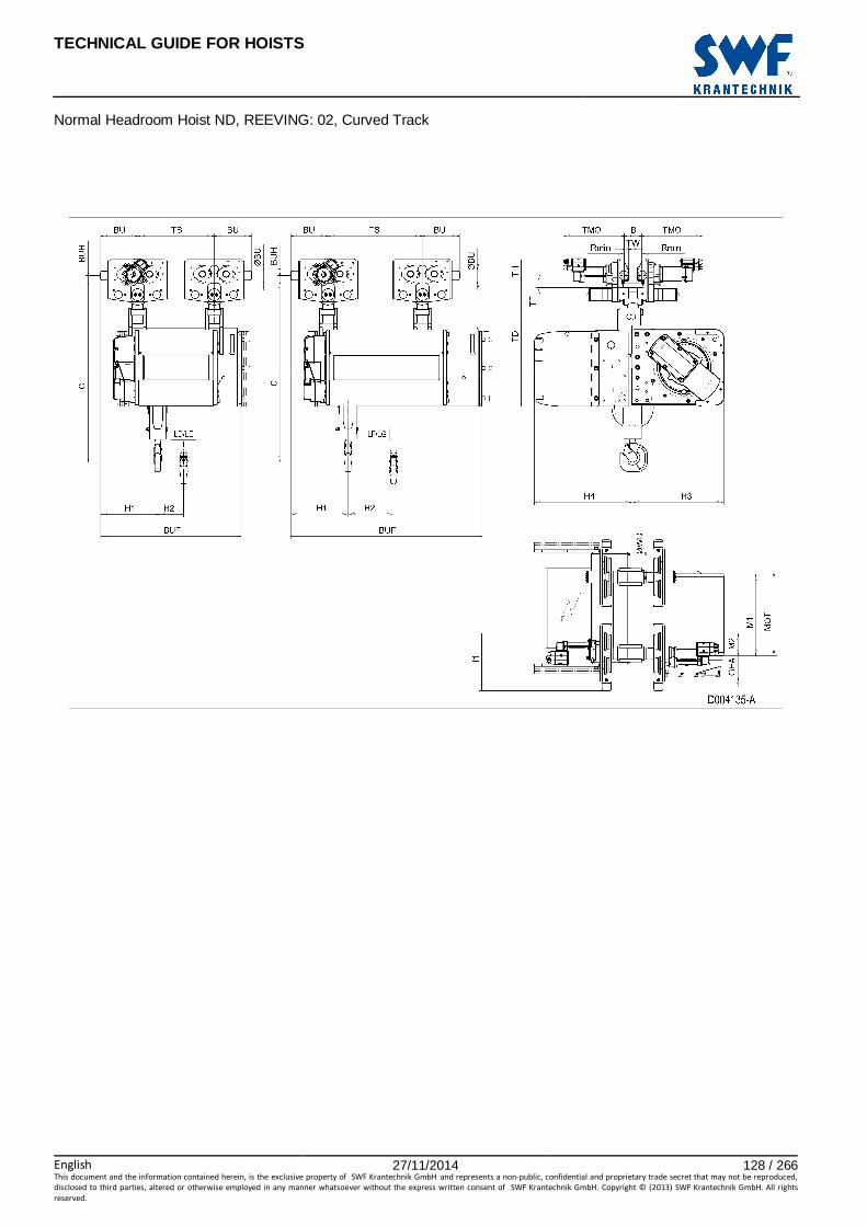
TECHNICAL GUIDE FOR HOISTS
English 27/11/2014 128 / 266This document and the information contained herein, is the exclusive property of SWF Krantechnik GmbH and represents a non-public, confidential and proprietary trade secret that may not be reproduced,
disclosed to third parties, altered or otherwise employed in any manner whatsoever without the express written consent of SWF Krantechnik GmbH. Copyright © (2013) SWF Krantechnik GmbH. All rights
reserved.
Normal Headroom Hoist ND, REEVING: 02, Curved Track

TECHNICAL GUIDE FOR HOISTS
English 27/11/2014 129 / 266This document and the information contained herein, is the exclusive property of SWF Krantechnik GmbH and represents a non-public, confidential and proprietary trade secret that may not be reproduced,
disclosed to third parties, altered or otherwise employed in any manner whatsoever without the express written consent of SWF Krantechnik GmbH. Copyright © (2013) SWF Krantechnik GmbH. All rights
reserved.
58 NORMAL HEADROOM HOIST ND, REEVING: 04
Hoist dimensions HOL Length M1 H1 H2 H3 H3* H4 Weight
m code mm mm mm mm mm mm kg
9 D 558 441 88 649 669 643 790
12 E 678 441 118 649 669 643 850
16 F 828 416 156 649 669 643 930
20 G 1018 416 204 649 669 643 990
Motor dimensions Travelling dimensions
Motor P5 P6 P7 A5 S5 S7 Motor MF06MA MF06LA MOT (mm) 578 578 618 498 606 757 TMO (mm) 360 400
Weight (kg) 58 85 105 45 53 81 Weight (kg) 5.7 7.8
Trolley dimensions
B min B max C ∅∅∅∅BU ∅∅∅∅WD BU BUH GEA M2 TD TF TH
80 610 1024 63 100 253 40 143 238 700 40 150
TW 31
D002120_A 062274
Trolley dimensions Length TS BUF code
D/E 494 924
F/G 522 1239
Note: All dimensions in mm. Note: Weight calculated with P6 motor, when B=300 mm. * Please, disregard the dimension H3*.
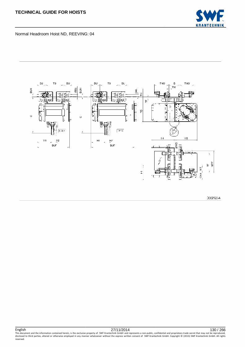
TECHNICAL GUIDE FOR HOISTS
English 27/11/2014 130 / 266This document and the information contained herein, is the exclusive property of SWF Krantechnik GmbH and represents a non-public, confidential and proprietary trade secret that may not be reproduced,
disclosed to third parties, altered or otherwise employed in any manner whatsoever without the express written consent of SWF Krantechnik GmbH. Copyright © (2013) SWF Krantechnik GmbH. All rights
reserved.
Normal Headroom Hoist ND, REEVING: 04

TECHNICAL GUIDE FOR HOISTS
English 27/11/2014 131 / 266This document and the information contained herein, is the exclusive property of SWF Krantechnik GmbH and represents a non-public, confidential and proprietary trade secret that may not be reproduced,
disclosed to third parties, altered or otherwise employed in any manner whatsoever without the express written consent of SWF Krantechnik GmbH. Copyright © (2013) SWF Krantechnik GmbH. All rights
reserved.
59 NORMAL HEADROOM HOIST ND, REEVING: 04, CURVED TR ACK
Hoist dimensions HOL Length M1 H1 H2 H3 H3* H4 Weight
m code mm mm mm mm mm mm kg
9 D 558 473 88 649 669 643 880
12 E 678 473 118 649 669 643 930
16 F 828 473 156 649 669 643 1000
20 G 1018 473 204 649 669 643 1090
Motor dimensions Travelling dimensions
Motor P5 P6 P7 A5 S5 S7 Motor MF06MA MF06LA MOT (mm) 578 578 618 498 606 757 TMO (mm) 360 400
Weight (kg) 58 85 105 45 53 81 Weight (kg) 5.7 7.8
Trolley dimensions
B min B max C ∅∅∅∅BU ∅∅∅∅WD BU BUH GEA M2 TD TF TH
90 350 1170 63 100 253 40 143 238 850 42 150
TW 31
D004136_A 062275
Trolley dimensions Length TS BUF code
D/E 520 957
F/G 640 1297
Track radius
B R min 90 - 109 2500
110 - 119 2000
120 - 350 1500
Note: All dimensions in mm. Note: Weight calculated with P5 motor. * Please, disregard the dimension H3*.

TECHNICAL GUIDE FOR HOISTS
English 27/11/2014 132 / 266This document and the information contained herein, is the exclusive property of SWF Krantechnik GmbH and represents a non-public, confidential and proprietary trade secret that may not be reproduced,
disclosed to third parties, altered or otherwise employed in any manner whatsoever without the express written consent of SWF Krantechnik GmbH. Copyright © (2013) SWF Krantechnik GmbH. All rights
reserved.
Normal Headroom Hoist ND, REEVING: 04, Curved Track

TECHNICAL GUIDE FOR HOISTS
English 27/11/2014 133 / 266This document and the information contained herein, is the exclusive property of SWF Krantechnik GmbH and represents a non-public, confidential and proprietary trade secret that may not be reproduced,
disclosed to third parties, altered or otherwise employed in any manner whatsoever without the express written consent of SWF Krantechnik GmbH. Copyright © (2013) SWF Krantechnik GmbH. All rights
reserved.
60 NORMAL HEADROOM HOIST ND, REEVING: 06
Hoist dimensions HOL Length M1 H1 H2 H3 H3* H4 Weight
m code mm mm mm mm mm mm kg
6 D 558 556 53 605 625 612 1030
8 E 678 556 78 605 625 612 1050
10 F 828 596 98 605 625 612 1140
13 G 1018 596 132 605 625 612 1195
Motor dimensions Travelling dimensions
Motor P5 P6 P7 A5 S5 S7 Motor MF06MA MF06LA MOT (mm) 578 578 618 498 606 757 TMO (mm) 360 400
Weight (kg) 58 85 105 45 53 81 Weight (kg) 5.7 7.8
Trolley dimensions
B min B max C ∅∅∅∅BU ∅∅∅∅WD BU BUH GEA M2 TD TF TH
110 610 1413 63 125 288 40 143 33 716 40 170
TW 41.5
D007206_A 124578
Trolley dimensions Length code
BF TS
D/E 110 600
F/G 370 720
Note: All dimensions in mm. Note: Weight calculated with P5 motor, when B=300 mm * Please, disregard the dimension H3*.
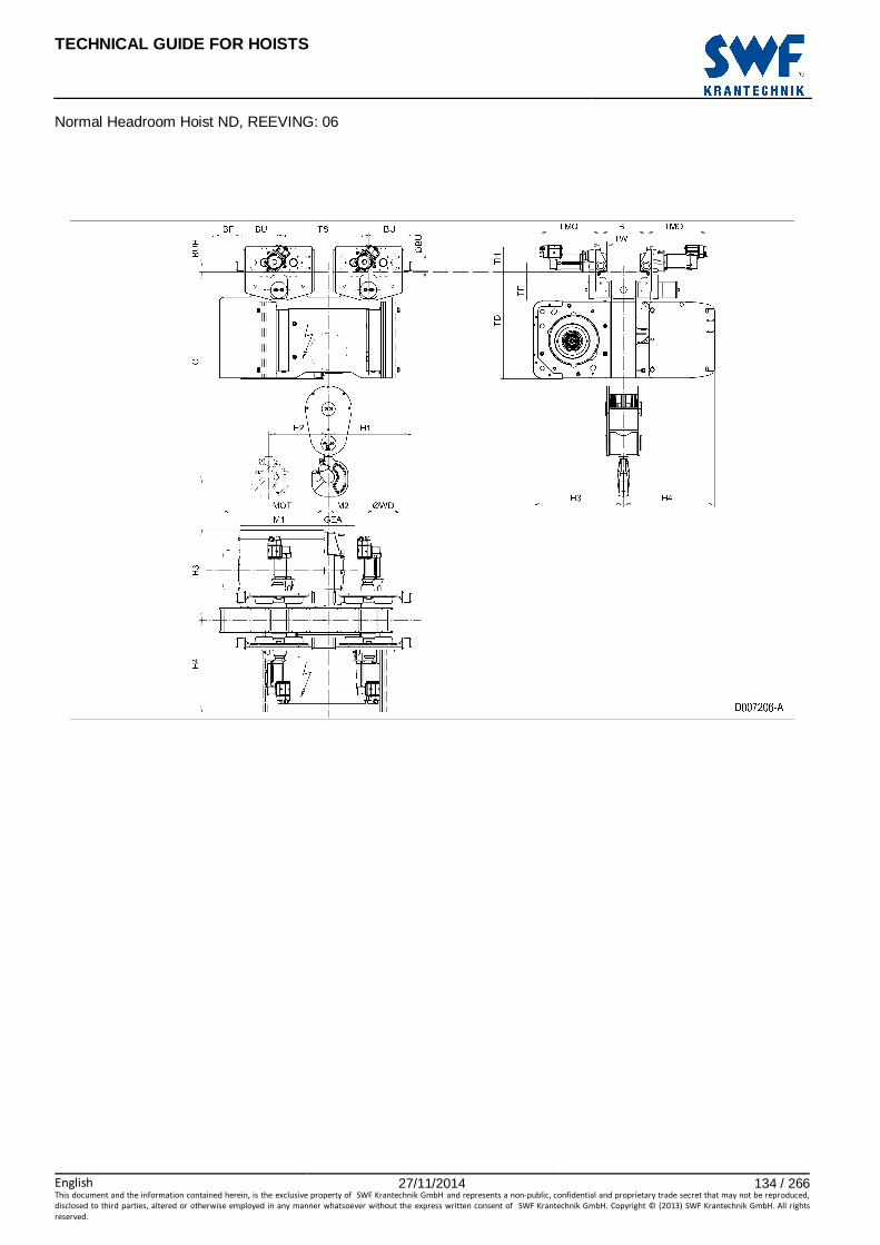
TECHNICAL GUIDE FOR HOISTS
English 27/11/2014 134 / 266This document and the information contained herein, is the exclusive property of SWF Krantechnik GmbH and represents a non-public, confidential and proprietary trade secret that may not be reproduced,
disclosed to third parties, altered or otherwise employed in any manner whatsoever without the express written consent of SWF Krantechnik GmbH. Copyright © (2013) SWF Krantechnik GmbH. All rights
reserved.
Normal Headroom Hoist ND, REEVING: 06

TECHNICAL GUIDE FOR HOISTS
English 27/11/2014 135 / 266This document and the information contained herein, is the exclusive property of SWF Krantechnik GmbH and represents a non-public, confidential and proprietary trade secret that may not be reproduced,
disclosed to third parties, altered or otherwise employed in any manner whatsoever without the express written consent of SWF Krantechnik GmbH. Copyright © (2013) SWF Krantechnik GmbH. All rights
reserved.
61 NORMAL HEADROOM HOIST ND, REEVING: 06, CURVED T RACK
Hoist dimensions HOL Length M1 H1 H2 H3 H3* H4 Weight
m code mm mm mm mm mm mm kg
6 D 558 556 53 605 625 612 1110
8 E 678 556 78 605 625 612 1155
10 F 828 596 98 605 625 612 1245
13 G 1018 596 132 605 625 612 1300
Motor dimensions Travelling dimensions
Motor P5 P6 P7 A5 S5 S7 Motor MF06MA MF06LA MOT (mm) 578 578 618 498 606 757 TMO (mm) 360 400
Weight (kg) 58 85 105 45 53 81 Weight (kg) 5.7 7.8
Trolley dimensions
B min B max C ∅∅∅∅BU ∅∅∅∅WD R min BU BUH GEA M2 TD TF
120 300 1568 63 125 2500 288 40 143 33 871 39.5
TH TW 170 41.5
D007207_A 124579
Trolley dimensions Length code
BF TS
D/E 110 600
F/G 370 720
Note: All dimensions in mm. Note: Weight calculated with P5 motor. * Please, disregard the dimension H3*.

TECHNICAL GUIDE FOR HOISTS
English 27/11/2014 136 / 266This document and the information contained herein, is the exclusive property of SWF Krantechnik GmbH and represents a non-public, confidential and proprietary trade secret that may not be reproduced,
disclosed to third parties, altered or otherwise employed in any manner whatsoever without the express written consent of SWF Krantechnik GmbH. Copyright © (2013) SWF Krantechnik GmbH. All rights
reserved.
Normal Headroom Hoist ND, REEVING: 06, Curved Track

TECHNICAL GUIDE FOR HOISTS
English 27/11/2014 137 / 266This document and the information contained herein, is the exclusive property of SWF Krantechnik GmbH and represents a non-public, confidential and proprietary trade secret that may not be reproduced,
disclosed to third parties, altered or otherwise employed in any manner whatsoever without the express written consent of SWF Krantechnik GmbH. Copyright © (2013) SWF Krantechnik GmbH. All rights
reserved.
62 NORMAL HEADROOM HOIST ND, REEVING: 08
Hoist dimensions HOL Length M1 H1 H2 H3 H3* H4 Weight
m code mm mm mm mm mm mm kg
4.5 D 558 556 44 605 625 612 1040
6 E 678 556 53 605 625 612 1060
8 F 828 596 76 605 625 612 1150
10 G 1018 596 98 605 625 612 1210
Motor dimensions Travelling dimensions
Motor P5 P6 P7 A5 S5 S7 Motor MF06MA MF06LA MOT (mm) 578 578 618 498 606 757 TMO (mm) 360 400
Weight (kg) 58 85 105 45 53 81 Weight (kg) 5.7 7.8
Trolley dimensions
B min B max C ∅∅∅∅BU ∅∅∅∅WD BU BUH GEA M2 TD TF TH
110 610 1413 63 125 288 40 143 33 716 39.5 170
TW 41.5
D007208_A 124580
Trolley dimensions Length code
BF TS
D/E 110 600
F/G 370 720
Note: All dimensions in mm. Note: Weight calculated with P5 motor, when B=300 mm. * Please, disregard the dimension H3*.
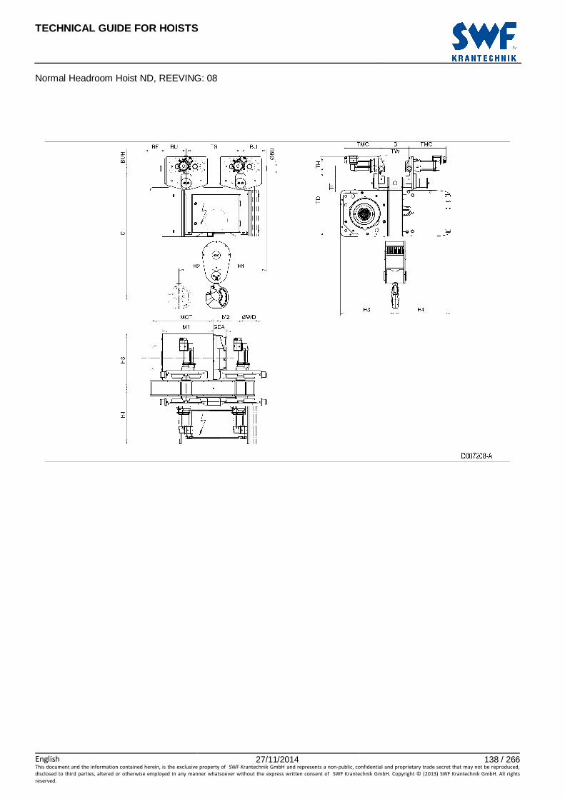
TECHNICAL GUIDE FOR HOISTS
English 27/11/2014 138 / 266This document and the information contained herein, is the exclusive property of SWF Krantechnik GmbH and represents a non-public, confidential and proprietary trade secret that may not be reproduced,
disclosed to third parties, altered or otherwise employed in any manner whatsoever without the express written consent of SWF Krantechnik GmbH. Copyright © (2013) SWF Krantechnik GmbH. All rights
reserved.
Normal Headroom Hoist ND, REEVING: 08

TECHNICAL GUIDE FOR HOISTS
English 27/11/2014 139 / 266This document and the information contained herein, is the exclusive property of SWF Krantechnik GmbH and represents a non-public, confidential and proprietary trade secret that may not be reproduced,
disclosed to third parties, altered or otherwise employed in any manner whatsoever without the express written consent of SWF Krantechnik GmbH. Copyright © (2013) SWF Krantechnik GmbH. All rights
reserved.
63 NORMAL HEADROOM HOIST ND, REEVING: 08, CURVED TR ACK
Hoist dimensions HOL Length M1 H1 H2 H3 H3* H4 Weight
m code mm mm mm mm mm mm kg
4.5 D 558 556 44 605 625 612 1120
6 E 678 556 53 605 625 612 1170
8 F 828 596 76 605 625 612 1260
10 G 1018 596 98 605 625 612 1315
Motor dimensions Travelling dimensions
Motor P5 P6 P7 A5 S5 S7 Motor MF06MA MF06LA MOT (mm) 578 578 618 498 606 757 TMO (mm) 360 400
Weight (kg) 58 85 105 45 53 81 Weight (kg) 5.7 7.8
Trolley dimensions
B min B max C ∅∅∅∅BU ∅∅∅∅WD R min BU BUH GEA M2 TD TF
120 300 1568 63 125 2500 288 40 143 33 716 39.5
TH TW
170 41.5
D007209_A 124581
Trolley dimensions Length code
BF TS
D/E 110 600
F/G 370 720
Note: All dimensions in mm. Note: Weight calculated with P5 motor. * Please, disregard the dimension H3*.

TECHNICAL GUIDE FOR HOISTS
English 27/11/2014 140 / 266This document and the information contained herein, is the exclusive property of SWF Krantechnik GmbH and represents a non-public, confidential and proprietary trade secret that may not be reproduced,
disclosed to third parties, altered or otherwise employed in any manner whatsoever without the express written consent of SWF Krantechnik GmbH. Copyright © (2013) SWF Krantechnik GmbH. All rights
reserved.
Normal Headroom Hoist ND, REEVING: 08, Curved Track
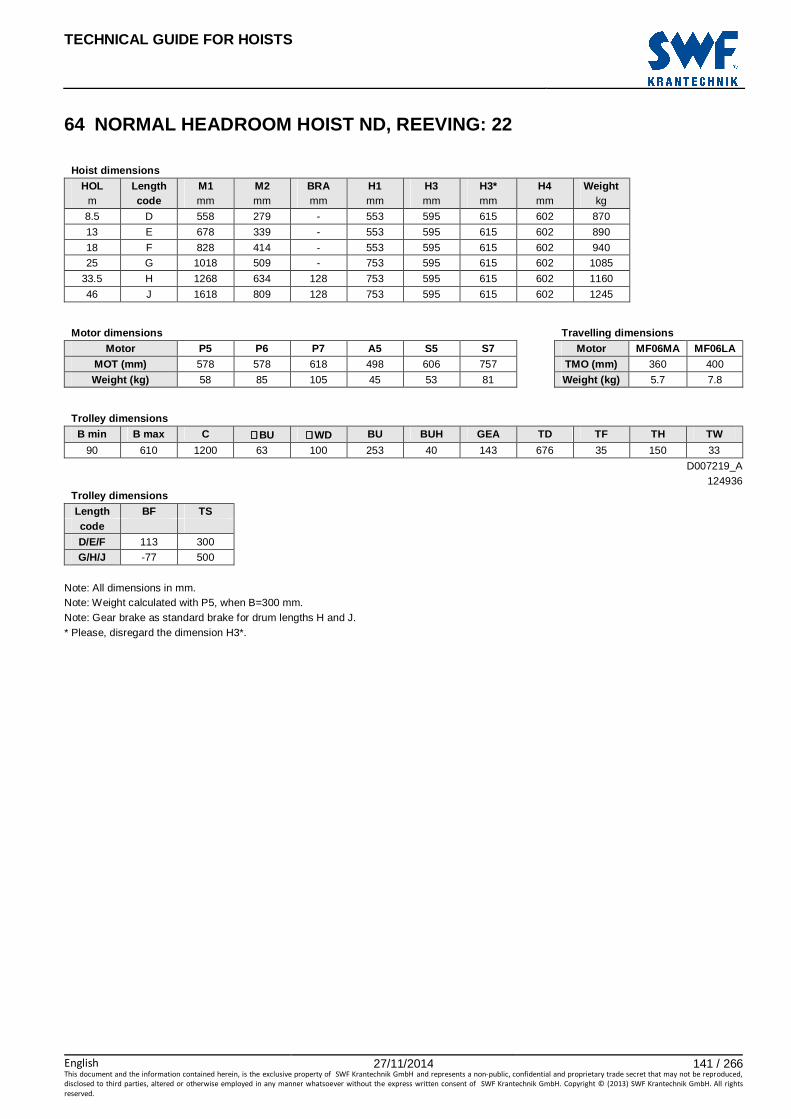
TECHNICAL GUIDE FOR HOISTS
English 27/11/2014 141 / 266This document and the information contained herein, is the exclusive property of SWF Krantechnik GmbH and represents a non-public, confidential and proprietary trade secret that may not be reproduced,
disclosed to third parties, altered or otherwise employed in any manner whatsoever without the express written consent of SWF Krantechnik GmbH. Copyright © (2013) SWF Krantechnik GmbH. All rights
reserved.
64 NORMAL HEADROOM HOIST ND, REEVING: 22
Hoist dimensions HOL Length M1 M2 BRA H1 H3 H3* H4 Weight
m code mm mm mm mm mm mm mm kg
8.5 D 558 279 - 553 595 615 602 870
13 E 678 339 - 553 595 615 602 890
18 F 828 414 - 553 595 615 602 940
25 G 1018 509 - 753 595 615 602 1085
33.5 H 1268 634 128 753 595 615 602 1160
46 J 1618 809 128 753 595 615 602 1245
Motor dimensions Travelling dimensions
Motor P5 P6 P7 A5 S5 S7 Motor MF06MA MF06LA MOT (mm) 578 578 618 498 606 757 TMO (mm) 360 400
Weight (kg) 58 85 105 45 53 81 Weight (kg) 5.7 7.8
Trolley dimensions
B min B max C ∅∅∅∅BU ∅∅∅∅WD BU BUH GEA TD TF TH TW
90 610 1200 63 100 253 40 143 676 35 150 33
D007219_A 124936
Trolley dimensions Length BF TS code
D/E/F 113 300
G/H/J -77 500
Note: All dimensions in mm. Note: Weight calculated with P5, when B=300 mm. Note: Gear brake as standard brake for drum lengths H and J. * Please, disregard the dimension H3*.

TECHNICAL GUIDE FOR HOISTS
English 27/11/2014 142 / 266This document and the information contained herein, is the exclusive property of SWF Krantechnik GmbH and represents a non-public, confidential and proprietary trade secret that may not be reproduced,
disclosed to third parties, altered or otherwise employed in any manner whatsoever without the express written consent of SWF Krantechnik GmbH. Copyright © (2013) SWF Krantechnik GmbH. All rights
reserved.
Normal Headroom Hoist ND, REEVING: 22

TECHNICAL GUIDE FOR HOISTS
English 27/11/2014 143 / 266This document and the information contained herein, is the exclusive property of SWF Krantechnik GmbH and represents a non-public, confidential and proprietary trade secret that may not be reproduced,
disclosed to third parties, altered or otherwise employed in any manner whatsoever without the express written consent of SWF Krantechnik GmbH. Copyright © (2013) SWF Krantechnik GmbH. All rights
reserved.
65 NORMAL HEADROOM HOIST ND, REEVING: 22, CURVED TR ACK
Hoist dimensions HOL Length M1 M2 BRA H1 H3 H3* H4 Weight
m code mm mm mm mm mm mm mm kg
8.5 D 558 279 - 553 595 615 602 890
13 E 678 339 - 553 595 615 602 945
18 F 828 414 - 553 595 615 602 1000
25 G 1018 509 - 753 595 615 602 1145
33.5 H 1268 634 128 753 595 615 602 1215
46 J 1618 809 128 753 595 615 602 1330
Motor dimensions Travelling dimensions
Motor P5 P6 P7 A5 S5 S7 Motor MF06MA MF06LA MOT (mm) 578 578 618 498 606 757 TMO (mm) 360 400
Weight (kg) 58 85 105 45 53 81 Weight (kg) 5.7 7.8
Trolley dimensions
B min B max C ∅∅∅∅BU ∅∅∅∅WD BU BUH GEA TD TF TH TW
90 350 1353 63 100 253 40 143 829 42 150 30.5
D007220_A 124937
Track radius Trolley dimensions
B R min Length BF TS 90 - 109 2500 code
110 - 119 2000 D/E/F 113 300
120 - 350 1500 G/H/J -77 500
Note: All dimensions in mm. Note: Weight calculated with P5 motor. Note: Gear brake as standard brake for drum lengths H and J. * Please, disregard the dimension H3*.

TECHNICAL GUIDE FOR HOISTS
English 27/11/2014 144 / 266This document and the information contained herein, is the exclusive property of SWF Krantechnik GmbH and represents a non-public, confidential and proprietary trade secret that may not be reproduced,
disclosed to third parties, altered or otherwise employed in any manner whatsoever without the express written consent of SWF Krantechnik GmbH. Copyright © (2013) SWF Krantechnik GmbH. All rights
reserved.
Normal Headroom Hoist ND, REEVING: 22, Curved Track

TECHNICAL GUIDE FOR HOISTS
English 27/11/2014 145 / 266This document and the information contained herein, is the exclusive property of SWF Krantechnik GmbH and represents a non-public, confidential and proprietary trade secret that may not be reproduced,
disclosed to third parties, altered or otherwise employed in any manner whatsoever without the express written consent of SWF Krantechnik GmbH. Copyright © (2013) SWF Krantechnik GmbH. All rights
reserved.
66 NORMAL HEADROOM HOIST ND, REEVING: 24
Hoist dimensions HOL Length M1 M2 BRA H1 H3 H3* H4 Weight
m code mm mm mm mm mm mm mm kg
4 D 558 279 - 553 595 615 602 950
6.5 E 678 339 - 553 595 615 602 970
9 F 828 414 - 553 595 615 602 1020
12.5 G 1018 509 - 753 595 615 602 1165
16.5 H 1268 634 128 753 595 615 602 1240
23 J 1618 809 128 753 595 615 602 1325
Motor dimensions Travelling dimensions
Motor P5 P6 P7 A5 S5 S7 Motor MF06MA MF06LA MOT (mm) 578 578 618 498 606 757 TMO (mm) 360 400
Weight (kg) 58 85 105 45 53 81 Weight (kg) 5.7 7.8
Trolley dimensions
B min B max C ∅∅∅∅BU ∅∅∅∅WD BU BUH GEA TD TF TH TW
90 610 1365 63 100 253 40 143 676 35 150 31
D007221_A 124938
Trolley dimensions Length BF TS code
D/E/F 113 300
G/H/J -77 500
Note: All dimensions in mm. Note: Weight calculated with P5 motor, when B=300 mm. Note: Gear brake as standard brake for drum lengths H and J. * Please, disregard the dimension H3*.
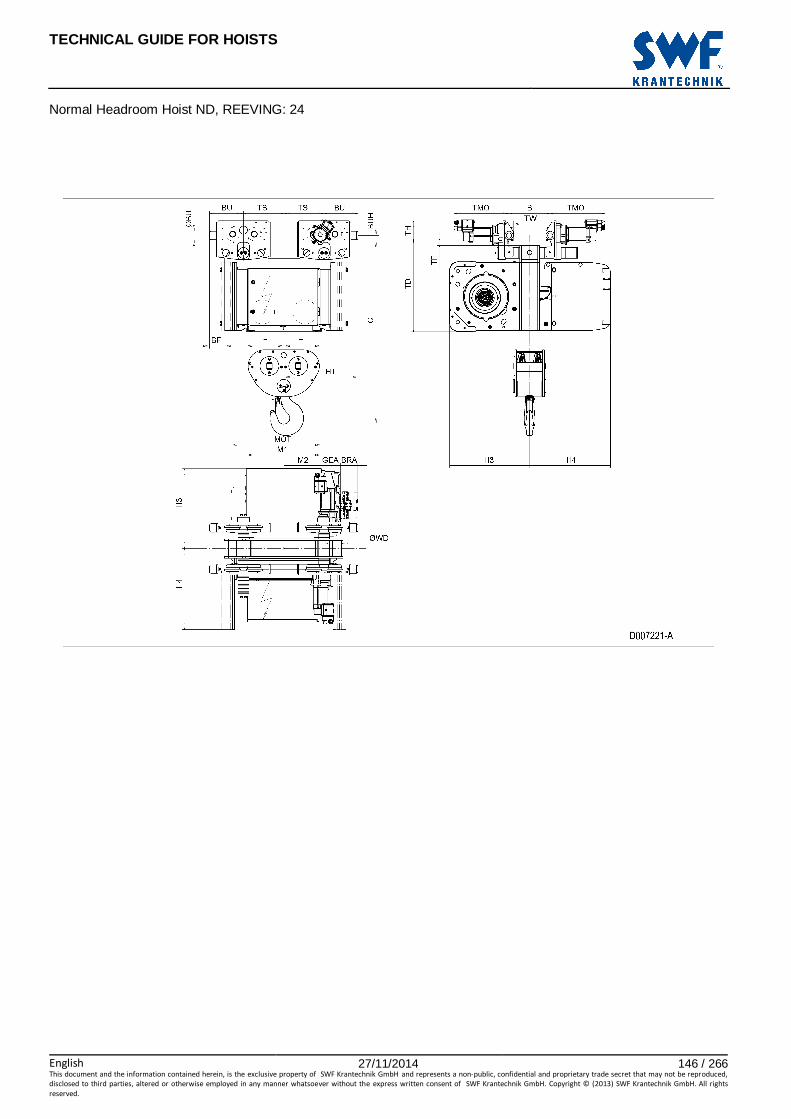
TECHNICAL GUIDE FOR HOISTS
English 27/11/2014 146 / 266This document and the information contained herein, is the exclusive property of SWF Krantechnik GmbH and represents a non-public, confidential and proprietary trade secret that may not be reproduced,
disclosed to third parties, altered or otherwise employed in any manner whatsoever without the express written consent of SWF Krantechnik GmbH. Copyright © (2013) SWF Krantechnik GmbH. All rights
reserved.
Normal Headroom Hoist ND, REEVING: 24

TECHNICAL GUIDE FOR HOISTS
English 27/11/2014 147 / 266This document and the information contained herein, is the exclusive property of SWF Krantechnik GmbH and represents a non-public, confidential and proprietary trade secret that may not be reproduced,
disclosed to third parties, altered or otherwise employed in any manner whatsoever without the express written consent of SWF Krantechnik GmbH. Copyright © (2013) SWF Krantechnik GmbH. All rights
reserved.
67 NORMAL HEADROOM HOIST ND, REEVING: 24, CURVED TR ACK
Hoist dimensions HOL Length M1 M2 BRA H1 H3 H3* H4 Weight
m code mm mm mm mm mm mm mm kg
4 D 558 279 - 553 595 615 602 980
6.5 E 678 339 - 553 595 615 602 1025
9 F 828 414 - 553 595 615 602 1075
12.5 G 1018 509 - 753 595 615 602 1220
16.5 H 1268 634 128 753 595 615 602 1295
23 J 1618 809 128 753 595 615 602 1405
Motor dimensions Travelling dimensions
Motor P5 P6 P7 A5 S5 S7 Motor MF06MA MF06LA MOT (mm) 578 578 618 498 606 757 TMO (mm) 360 400
Weight (kg) 58 85 105 45 53 81 Weight (kg) 5.7 7.8
Trolley dimensions
B min B max C ∅∅∅∅BU ∅∅∅∅WD BU BUH GEA TD TF TH TW
90 350 1518 63 100 253 40 143 829 42 150 31
D007222_A 124939
Track radius Trolley dimensions B R min Length BF TS
90 - 109 2500 code
110 - 119 2000 D/E/F 113 300
120 - 350 1500 G/H/J -77 500
Note: All dimensions in mm. Note: Weight calculated with P5 motor. Note: Gear brake as standard brake for drum lengths H and J. * Please, disregard the dimension H3*.

TECHNICAL GUIDE FOR HOISTS
English 27/11/2014 148 / 266This document and the information contained herein, is the exclusive property of SWF Krantechnik GmbH and represents a non-public, confidential and proprietary trade secret that may not be reproduced,
disclosed to third parties, altered or otherwise employed in any manner whatsoever without the express written consent of SWF Krantechnik GmbH. Copyright © (2013) SWF Krantechnik GmbH. All rights
reserved.
Normal Headroom Hoist ND, REEVING: 24, Curved Track
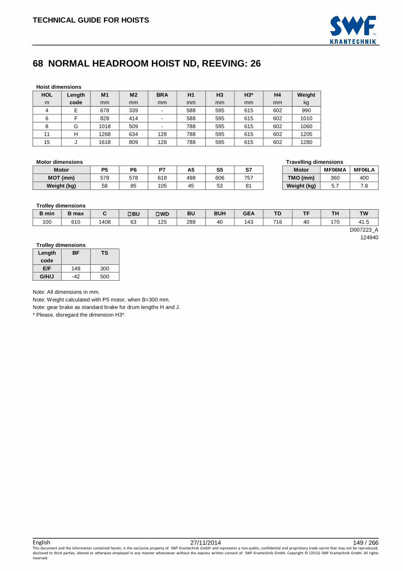
TECHNICAL GUIDE FOR HOISTS
English 27/11/2014 149 / 266This document and the information contained herein, is the exclusive property of SWF Krantechnik GmbH and represents a non-public, confidential and proprietary trade secret that may not be reproduced,
disclosed to third parties, altered or otherwise employed in any manner whatsoever without the express written consent of SWF Krantechnik GmbH. Copyright © (2013) SWF Krantechnik GmbH. All rights
reserved.
68 NORMAL HEADROOM HOIST ND, REEVING: 26
Hoist dimensions HOL Length M1 M2 BRA H1 H3 H3* H4 Weight
m code mm mm mm mm mm mm mm kg
4 E 678 339 - 588 595 615 602 990
6 F 828 414 - 588 595 615 602 1010
8 G 1018 509 - 788 595 615 602 1060
11 H 1268 634 128 788 595 615 602 1205
15 J 1618 809 128 788 595 615 602 1280
Motor dimensions Travelling dimensions
Motor P5 P6 P7 A5 S5 S7 Motor MF06MA MF06LA MOT (mm) 578 578 618 498 606 757 TMO (mm) 360 400
Weight (kg) 58 85 105 45 53 81 Weight (kg) 5.7 7.8
Trolley dimensions
B min B max C ∅∅∅∅BU ∅∅∅∅WD BU BUH GEA TD TF TH TW
100 610 1408 63 125 288 40 143 716 40 170 41.5
D007223_A 124940
Trolley dimensions Length BF TS code
E/F 148 300
G/H/J -42 500
Note: All dimensions in mm. Note: Weight calculated with P5 motor, when B=300 mm. Note: gear brake as standard brake for drum lengths H and J. * Please, disregard the dimension H3*.

TECHNICAL GUIDE FOR HOISTS
English 27/11/2014 150 / 266This document and the information contained herein, is the exclusive property of SWF Krantechnik GmbH and represents a non-public, confidential and proprietary trade secret that may not be reproduced,
disclosed to third parties, altered or otherwise employed in any manner whatsoever without the express written consent of SWF Krantechnik GmbH. Copyright © (2013) SWF Krantechnik GmbH. All rights
reserved.
Normal Headroom Hoist ND, REEVING: 26

TECHNICAL GUIDE FOR HOISTS
English 27/11/2014 151 / 266This document and the information contained herein, is the exclusive property of SWF Krantechnik GmbH and represents a non-public, confidential and proprietary trade secret that may not be reproduced,
disclosed to third parties, altered or otherwise employed in any manner whatsoever without the express written consent of SWF Krantechnik GmbH. Copyright © (2013) SWF Krantechnik GmbH. All rights
reserved.
69 NORMAL HEADROOM HOIST ND, REEVING: 26, CURVED TR ACK
Hoist dimensions HOL Length M1 M2 BRA H1 H3 H3* H4 Weight
m code mm mm mm mm mm mm mm kg
4 E 678 339 - 588 595 615 602 1115
6 F 828 414 - 588 595 615 602 1165
8 G 1018 509 - 788 595 615 602 1310
11 H 1268 634 128 788 595 615 602 1385
15 J 1618 809 128 788 595 615 602 1495
Motor dimensions Travelling dimensions
Motor P5 P6 P7 A5 S5 S7 Motor MF06MA MF06LA MOT (mm) 578 578 618 498 606 757 TMO (mm) 360 400
Weight (kg) 58 85 105 45 53 81 Weight (kg) 5.7 7.8
Trolley dimensions
B min B max C ∅∅∅∅BU ∅∅∅∅WD R min BU BUH GEA TD TF TH
120 300 1563 63 125 2500 288 40 143 871 40 170
TW 41.5
D007224_A 124941
Trolley dimensions Length BF TS code
E/F 148 300
G/H/J -42 500
Note: All dimensions in mm. Note: Weight calculated with P5 motor. Note: Gear brake as standard brake for drum lengths H and J. * Please, disregard the dimension H3*.

TECHNICAL GUIDE FOR HOISTS
English 27/11/2014 152 / 266This document and the information contained herein, is the exclusive property of SWF Krantechnik GmbH and represents a non-public, confidential and proprietary trade secret that may not be reproduced,
disclosed to third parties, altered or otherwise employed in any manner whatsoever without the express written consent of SWF Krantechnik GmbH. Copyright © (2013) SWF Krantechnik GmbH. All rights
reserved.
Normal Headroom Hoist ND, REEVING: 26, Curved Track

TECHNICAL GUIDE FOR HOISTS
English 27/11/2014 153 / 266This document and the information contained herein, is the exclusive property of SWF Krantechnik GmbH and represents a non-public, confidential and proprietary trade secret that may not be reproduced,
disclosed to third parties, altered or otherwise employed in any manner whatsoever without the express written consent of SWF Krantechnik GmbH. Copyright © (2013) SWF Krantechnik GmbH. All rights
reserved.
70 NORMAL HEADROOM HOIST ND, REEVING: 28
Hoist dimensions HOL Length M1 M2 BRA H1 H3 H3* H4 Weight
m code mm mm mm mm mm mm mm kg
4.5 F 828 414 - 588 595 615 602 1075
6 G 1018 509 - 788 595 615 602 1220
8 H 1268 634 128 788 595 615 602 1295
11.5 J 1618 809 128 788 595 615 602 1380
Motor dimensions Travelling dimensions
Motor P5 P6 P7 A5 S5 S7 Motor MF06MA MF06LA MOT (mm) 578 578 618 498 606 757 TMO (mm) 360 400
Weight (kg) 58 85 105 45 53 81 Weight (kg) 5.7 7.8
Trolley dimensions
B min B max C ∅∅∅∅BU ∅∅∅∅WD BU BUH GEA TD TF TH TW
100 610 1408 63 125 288 40 143 716 40 170 41.5
D007225_A 124942
Trolley dimensions Length BF TS code
F 148 300
G/H/J -42 500
Note: All dimensions in mm. Note: Weight calculated with P5 motor, when B=300 mm. Note: Gear brake as standard brake for drum lengths H and J. * Please, disregard the dimension H3*.

TECHNICAL GUIDE FOR HOISTS
English 27/11/2014 154 / 266This document and the information contained herein, is the exclusive property of SWF Krantechnik GmbH and represents a non-public, confidential and proprietary trade secret that may not be reproduced,
disclosed to third parties, altered or otherwise employed in any manner whatsoever without the express written consent of SWF Krantechnik GmbH. Copyright © (2013) SWF Krantechnik GmbH. All rights
reserved.
Normal Headroom Hoist ND, REEVING: 28

TECHNICAL GUIDE FOR HOISTS
English 27/11/2014 155 / 266This document and the information contained herein, is the exclusive property of SWF Krantechnik GmbH and represents a non-public, confidential and proprietary trade secret that may not be reproduced,
disclosed to third parties, altered or otherwise employed in any manner whatsoever without the express written consent of SWF Krantechnik GmbH. Copyright © (2013) SWF Krantechnik GmbH. All rights
reserved.
71 NORMAL HEADROOM HOIST ND, REEVING: 28, CURVED TR ACK
Hoist dimensions HOL Length M1 M2 BRA H1 H3 H3* H4 Weight
m code mm mm mm mm mm mm mm kg
4.5 F 828 414 - 588 595 615 602 1180
6 G 1018 509 - 788 595 615 602 1325
8 H 1268 634 128 788 595 615 602 1400
11.5 J 1618 809 128 788 595 615 602 1510
Motor dimensions Travelling dimensions
Motor P5 P6 P7 A5 S5 S7 Motor MF06MA MF06LA MOT (mm) 578 578 618 498 606 757 TMO (mm) 360 400
Weight (kg) 58 85 105 45 53 81 Weight (kg) 5.7 7.8
Trolley dimensions
B min B max C ∅∅∅∅BU ∅∅∅∅WD R min BU BUH GEA TD TF TH
120 300 1563 63 125 2500 288 40 143 871 40 170
TW 41.5
D007226_A 124943
Trolley dimensions Length BF TS code
F 148 300
G/H/J -42 500
Note: All dimensions in mm. Note: Weight calculated with P5 motor. Note: Gear brake as standard brake for drum lengths H and J. * Please, disregard the dimension H3*.
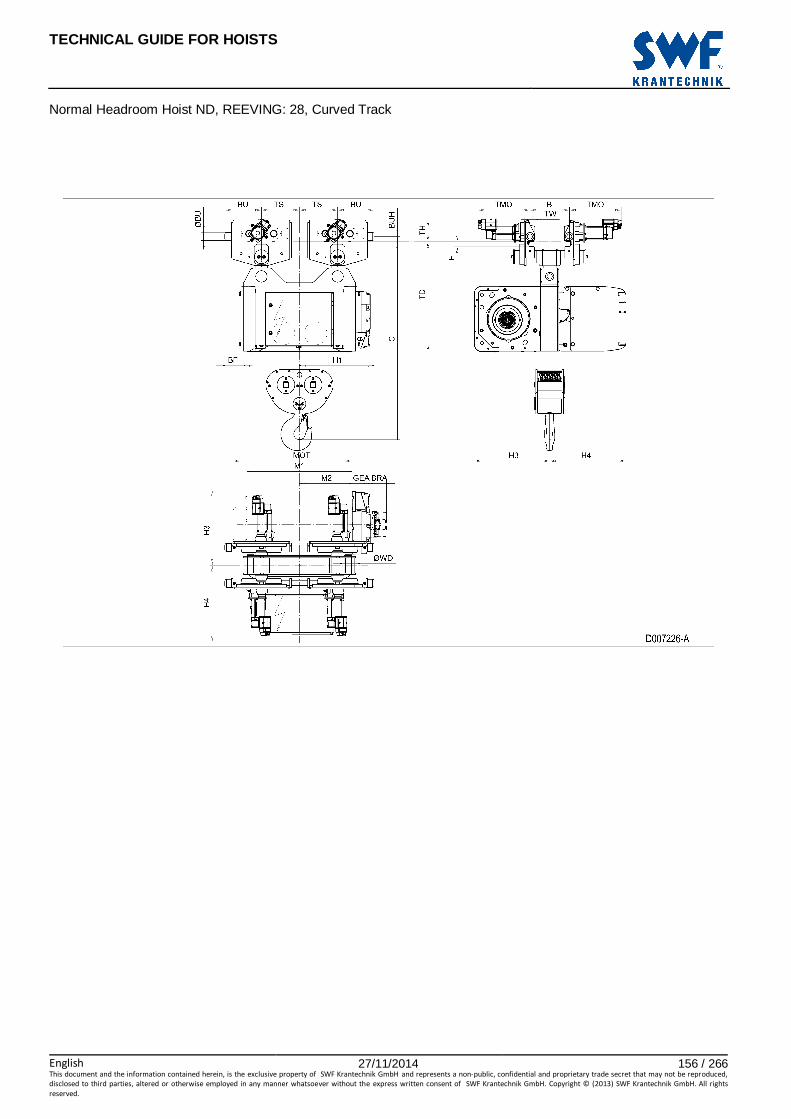
TECHNICAL GUIDE FOR HOISTS
English 27/11/2014 156 / 266This document and the information contained herein, is the exclusive property of SWF Krantechnik GmbH and represents a non-public, confidential and proprietary trade secret that may not be reproduced,
disclosed to third parties, altered or otherwise employed in any manner whatsoever without the express written consent of SWF Krantechnik GmbH. Copyright © (2013) SWF Krantechnik GmbH. All rights
reserved.
Normal Headroom Hoist ND, REEVING: 28, Curved Track

TECHNICAL GUIDE FOR HOISTS
English 27/11/2014 157 / 266This document and the information contained herein, is the exclusive property of SWF Krantechnik GmbH and represents a non-public, confidential and proprietary trade secret that may not be reproduced,
disclosed to third parties, altered or otherwise employed in any manner whatsoever without the express written consent of SWF Krantechnik GmbH. Copyright © (2013) SWF Krantechnik GmbH. All rights
reserved.
72 NORMAL HEADROOM HOIST NE, REEVING: 02
Hoist dimensions HOL HOL* Length
Code E11 M1 M2 TS BF H1 H2 H3 H4 Weight
A** Weight
B** m m mm mm mm mm mm mm mm mm mm kg kg
15.5 10 C 605 462 610 1310 88 838 139 871 756 2000 2200
21 15.5 D 605 562 610 1310 88 838 188 871 756 2000 2300
28 22.5 E 605 682 560 1540 88 788 251 871 756 2200 2400
36 30.5 F 605 832 560 1540 88 788 322 871 756 2300 2500
47 41.5 G 605 1022 640 2050 88 868 421 871 756 2500 2700
61 55.5 H 605 1272 640 2050 88 868 546 871 756 2700 2900
80.5 75 J 1064 1622 600 1910 -371 828 721 871 756 3100 3400
97 91.5 K 1064 1922 600 1910 -371 828 868 871 756 3300 3600
*HOL with drum brake **Presence of a drum brake will increase weight by 80 kgs.
Motor dimensions Travelling dimensions
Motor P6 P7 P8 A7 S7 S8 SA Motor MF06LA MOT (mm) 536 576 711 536 715 763 803 TMO (mm) 400
Weight (kg) 85 105 106 71 81 97 120 Weight (kg) 7.8
Trolley dimensions B1 min B1 max B2 min B2 max C ∅∅∅∅BU ∅∅∅∅WD Min R BU BUH E1 E2
120 610 180 320 1752 63 125 2500 288 40 605 959
E3 GEA M3 TD TF TH TW
126 218 44 998 35 170 41.5
D006985_A 103527
Note: All dimensions in mm. Note: Weight calculated with P6 motor when B=300 mm. Note: Dimensions B1 min, B1 max and Weight A for normal track suspension. Note: Dimensions B2 min, B2 max, Weight B and Min R for curved track suspension (option).

TECHNICAL GUIDE FOR HOISTS
English 27/11/2014 158 / 266This document and the information contained herein, is the exclusive property of SWF Krantechnik GmbH and represents a non-public, confidential and proprietary trade secret that may not be reproduced,
disclosed to third parties, altered or otherwise employed in any manner whatsoever without the express written consent of SWF Krantechnik GmbH. Copyright © (2013) SWF Krantechnik GmbH. All rights
reserved.
Normal Headroom Hoist NE, REEVING: 02 Note: For hoists with Solo electric provisions and a hoisting inverter, a special cubicle layout is required. Please consult the factory. Note: Detail view A for normal track suspension. Detail view B for curved track suspension (option). Note: X points the location for an auxiliary electrical cubicle.

TECHNICAL GUIDE FOR HOISTS
English 27/11/2014 159 / 266This document and the information contained herein, is the exclusive property of SWF Krantechnik GmbH and represents a non-public, confidential and proprietary trade secret that may not be reproduced,
disclosed to third parties, altered or otherwise employed in any manner whatsoever without the express written consent of SWF Krantechnik GmbH. Copyright © (2013) SWF Krantechnik GmbH. All rights
reserved.
73 NORMAL HEADROOM HOIST NE, REEVING: 04
Hoist dimensions HOL HOL* Length
Code E11 M1 M2 TS BF H1 H2 H3 H4 Weight
A** Weight
B** m m mm mm mm mm mm mm mm mm mm kg kg 7.5 4.5 C 605 462 610 1310 165 915 69 871 756 2300 2500
10.5 7.5 D 605 562 610 1310 165 915 94 871 756 2300 2600
14 11 E 1085 682 560 1060 -315 865 125 871 756 2500 2700
18 15 F 1085 832 560 1060 -315 865 161 871 756 2600 2800
23.5 20.5 G 1255 1022 640 1400 -485 945 210 871 756 2800 3000
30.5 27.5 H 1255 1272 640 1400 -485 945 273 871 756 3000 3200
40 37 J 1574 1622 600 1400 -804 905 360 871 756 3400 3600
48.5 45.5 K 1574 1922 600 1400 -804 905 434 871 756 3600 3900
*HOL with drum brake **Presence of a drum brake will increase weight by 80 kgs.
Motor dimensions Travelling dimensions
Motor P6 P7 P8 A7 S7 S8 SA Motor MF06LA MOT (mm) 536 576 711 536 715 763 803 TMO (mm) 431
Weight (kg) 85 105 106 71 81 97 120 Weight (kg) 7.8
Trolley dimensions B1 min B1 max B2 min B2 max C ∅∅∅∅BU ∅∅∅∅WD Min R BU BUH E1 E2
130 610 180 320 1762 80 180 4000 365 53 605 959
E3 GEA M3 TD TF TH TW
126 218 44 1008 45 208 53
D006986_A 103528
Note: All dimensions in mm. Note: Weight calculated with P6 motor when B=300 mm. Note: Dimensions B1 min, B1 max and Weight A for normal track suspension. Note: Dimensions B2 min, B2 max, Weight B and Min R for curved track suspension (option).

TECHNICAL GUIDE FOR HOISTS
English 27/11/2014 160 / 266This document and the information contained herein, is the exclusive property of SWF Krantechnik GmbH and represents a non-public, confidential and proprietary trade secret that may not be reproduced,
disclosed to third parties, altered or otherwise employed in any manner whatsoever without the express written consent of SWF Krantechnik GmbH. Copyright © (2013) SWF Krantechnik GmbH. All rights
reserved.
Normal Headroom Hoist NE, REEVING: 04 Note: For hoists with Solo electric provisions and a hoisting inverter, a special cubicle layout is required. Please consult the factory. Note: Detail view A for normal track suspension. Detail view B for curved track suspension (option). Note: X points the location for an auxiliary electrical cubicle.

TECHNICAL GUIDE FOR HOISTS
English 27/11/2014 161 / 266This document and the information contained herein, is the exclusive property of SWF Krantechnik GmbH and represents a non-public, confidential and proprietary trade secret that may not be reproduced,
disclosed to third parties, altered or otherwise employed in any manner whatsoever without the express written consent of SWF Krantechnik GmbH. Copyright © (2013) SWF Krantechnik GmbH. All rights
reserved.
74 NORMAL HEADROOM HOIST NE, REEVING: 06
Hoist dimensions HOL HOL* Length
Code E11 M1 M2 TS BF H1 H2 H3 H4 Weight
A** Weight
B** m m mm mm mm mm mm mm mm mm mm kg kg 5 3 C 605 462 610 1310 165 915 46 871 756 2400 2600
7 5 D 605 562 610 1310 165 915 63 871 756 2400 2700
9 7 E 1085 682 560 1060 -315 865 84 871 756 2600 2800
12 10 F 1085 832 560 1060 -315 865 107 871 756 2700 2900
15.5 13.5 G 1255 1022 640 1400 -485 945 140 871 756 2900 3100
20 18 H 1255 1272 640 1400 -485 945 182 871 756 3100 3300
26.5 24.5 J 1574 1622 600 1400 -804 905 240 871 756 3500 3700
32 30 K 1574 1922 600 1400 -804 905 289 871 756 3700 4000
*HOL with drum brake **Presence of a drum brake will increase weight by 80 kgs.
Motor dimensions Travelling dimensions
Motor P6 P7 P8 A7 S7 S8 SA Motor MF06LA MOT (mm) 536 576 711 536 715 763 803 TMO (mm) 431
Weight (kg) 85 105 106 71 81 97 120 Weight (kg) 7.8
Trolley dimensions B1 min B1 max B2 min B2 max C ∅∅∅∅BU ∅∅∅∅WD Min R BU BUH E1 E2
130 610 180 320 1881 80 180 4000 365 53 605 959
E3 GEA M3 TD TF TH TW
126 218 44 1008 45 208 53
D006987_A 103529
Note: All dimensions in mm. Note: Weight calculated with P6 motor when B=300 mm. Note: Dimensions B1 min, B1 max and Weight A for normal track suspension. Note: Dimensions B2 min, B2 max,Weight B and Min R for curved track suspension (option).

TECHNICAL GUIDE FOR HOISTS
English 27/11/2014 162 / 266This document and the information contained herein, is the exclusive property of SWF Krantechnik GmbH and represents a non-public, confidential and proprietary trade secret that may not be reproduced,
disclosed to third parties, altered or otherwise employed in any manner whatsoever without the express written consent of SWF Krantechnik GmbH. Copyright © (2013) SWF Krantechnik GmbH. All rights
reserved.
Normal Headroom Hoist NE, REEVING: 06 Note: For hoists with Solo electric provisions and a hoisting inverter, a special cubicle layout is required. Please consult the factory. Note: Detail view A for normal track suspension. Detail view B for curved track suspension (option). Note: X points the location for an auxiliary electrical cubicle.

TECHNICAL GUIDE FOR HOISTS
English 27/11/2014 163 / 266This document and the information contained herein, is the exclusive property of SWF Krantechnik GmbH and represents a non-public, confidential and proprietary trade secret that may not be reproduced,
disclosed to third parties, altered or otherwise employed in any manner whatsoever without the express written consent of SWF Krantechnik GmbH. Copyright © (2013) SWF Krantechnik GmbH. All rights
reserved.
75 NORMAL HEADROOM HOIST NE, REEVING: 22
Hoist dimensions HOL HOL* Length E1 M1 M2 H3 H4 TS BF Weight
A** Weight
B** m m code mm mm mm mm mm mm mm kg kg
16.5 9 E 605 682 314 848 733 655 93 2000 2200
22 14.5 F 605 832 239 848 733 655 93 2100 2300
29.5 22 G 605 1022 144 848 733 655 93 2300 2500
39 31.5 H 605 1272 319 848 733 955 93 2500 2800
52 44.5 J 605 1622 144 848 733 955 93 2800 3100
63.5 56 K 925 1922 -306 848 733 655 -227 3000 3300
77 69.5 L 925 2272 -481 848 733 655 -227 3300 3600
86.5 79 M 900 2522 -306 848 733 955 -202 3600 4000
98 90.5 N 900 2822 -456 848 733 955 -202 3800 4300
*HOL with drum brake **Presence of a drum brake will increase weight by 80 kgs.
Motor dimensions Travelling dimensions
Motor P6 P7 P8 A7 S7 S8 SA Motor MF06LA MOT (mm) 536 576 711 536 715 763 803 TMO (mm) 400
Weight (kg) 85 105 106 71 81 97 120 Weight (kg) 7.8
Trolley dimensions B1 min B1 max B2 min B2 max C ∅∅∅∅BU ∅∅∅∅WD Min R BU BUH E2 E3
120 610 180 320 1667 63 125 2500 288 40 979 126
GEA M3 TD TF TH TW
218 44 998 35 170 41.5
D006895_A 101302
Note: All dimensions in mm. Note: Weight calculated with P6 motor when B=300 mm. Note: Dimensions B1 min, B1 max and Weight A for normal track suspension. Note: Dimensions B2 min, B2 max, Weight B and Min R for curved track suspension (option).

TECHNICAL GUIDE FOR HOISTS
English 27/11/2014 164 / 266This document and the information contained herein, is the exclusive property of SWF Krantechnik GmbH and represents a non-public, confidential and proprietary trade secret that may not be reproduced,
disclosed to third parties, altered or otherwise employed in any manner whatsoever without the express written consent of SWF Krantechnik GmbH. Copyright © (2013) SWF Krantechnik GmbH. All rights
reserved.
Normal Headroom Hoist NE, REEVING: 22 Note: For hoists with Solo electric provisions and a hoisting inverter, a special cubicle layout is required. Please consult the factory. Note: Detail view A for normal track suspension. Detail view B for curved track suspension (option). Note: X points the location for an auxiliary electrical cubicle.

TECHNICAL GUIDE FOR HOISTS
English 27/11/2014 165 / 266This document and the information contained herein, is the exclusive property of SWF Krantechnik GmbH and represents a non-public, confidential and proprietary trade secret that may not be reproduced,
disclosed to third parties, altered or otherwise employed in any manner whatsoever without the express written consent of SWF Krantechnik GmbH. Copyright © (2013) SWF Krantechnik GmbH. All rights
reserved.
76 NORMAL HEADROOM HOIST NE, REEVING: 24
Hoist dimensions HOL HOL* Length
code E1 M1 M2 H3 H4 TS BF Weight
A** Weight
B**
m m mm mm mm mm mm mm mm kg kg
8 4 E 605 682 314 848 733 655 93 2100 2300
11 7 F 605 832 239 848 733 655 93 2200 2400
14.5 10.5 G 605 1022 144 848 733 655 93 2400 2600
19.5 15.5 H 605 1272 319 848 733 955 93 2600 2900
26 22 J 605 1622 144 848 733 955 93 2900 3100
31.5 27.5 K 925 1922 -306 848 733 655 -227 3100 3400
38.5 34.5 L 925 2272 -481 848 733 655 -227 3400 3700
43 39 M 900 2522 -306 848 733 955 -202 3700 4100
49 45 N 900 2822 -456 848 733 955 -202 3900 4300
*HOL with drum brake **Presence of a drum brake will increase weight by 80 kgs.
Motor dimensions Travelling dimensions
Motor P6 P7 P8 A7 S7 S8 SA Motor MF06LA MOT (mm) 536 576 711 536 715 763 803 TMO (mm) 400
Weight (kg) 85 105 106 71 81 97 120 Weight (kg) 7.8
Trolley dimensions B1 min B1 max B2 min B2 max C ∅∅∅∅BU ∅∅∅∅WD Min R BU BUH E2 E3
120 610 180 320 1975 63 125 2500 288 40 979 126
GEA M3 TD TF TH TW
218 44 998 35 170 41.5
D006896_A 101303
Note: All dimensions in mm. Note: Weight calculated with P6 motor when B=300 mm. Note: Dimensions B1 min, B1 max and Weight A for normal track suspension. Note: Dimensions B2 min, B2 max, Weight B and Min R for curved track suspension (option).
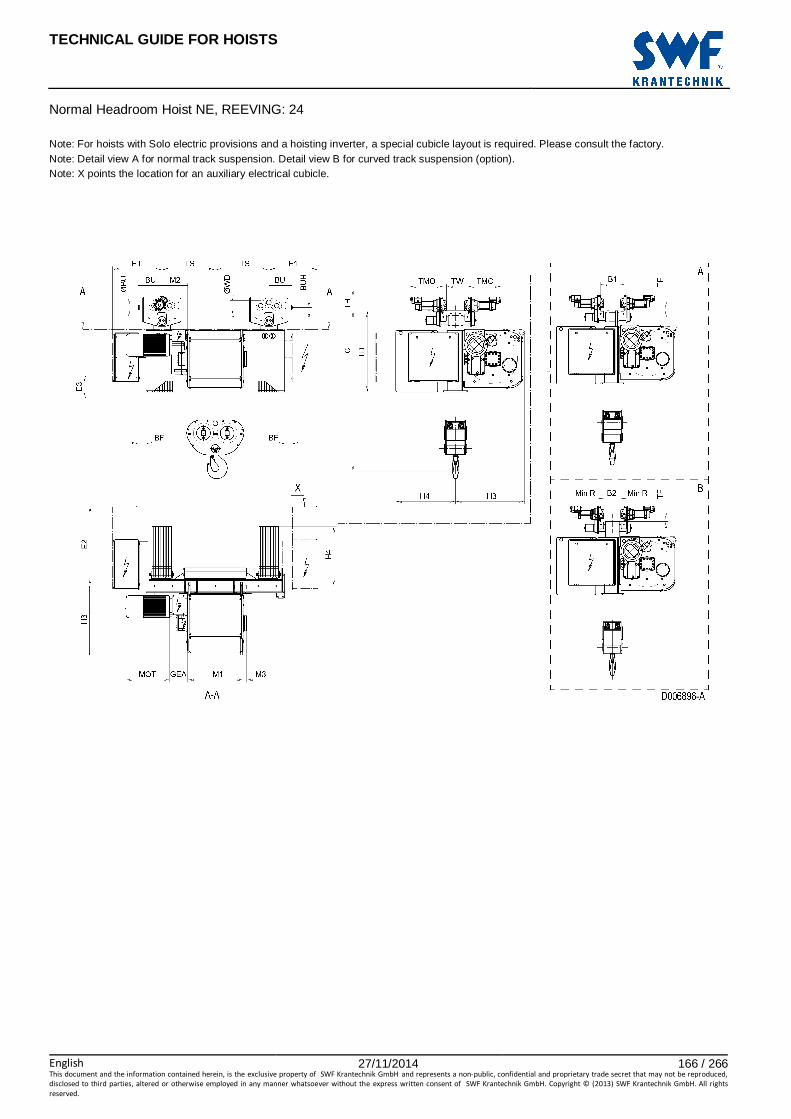
TECHNICAL GUIDE FOR HOISTS
English 27/11/2014 166 / 266This document and the information contained herein, is the exclusive property of SWF Krantechnik GmbH and represents a non-public, confidential and proprietary trade secret that may not be reproduced,
disclosed to third parties, altered or otherwise employed in any manner whatsoever without the express written consent of SWF Krantechnik GmbH. Copyright © (2013) SWF Krantechnik GmbH. All rights
reserved.
Normal Headroom Hoist NE, REEVING: 24 Note: For hoists with Solo electric provisions and a hoisting inverter, a special cubicle layout is required. Please consult the factory. Note: Detail view A for normal track suspension. Detail view B for curved track suspension (option). Note: X points the location for an auxiliary electrical cubicle.

TECHNICAL GUIDE FOR HOISTS
English 27/11/2014 167 / 266This document and the information contained herein, is the exclusive property of SWF Krantechnik GmbH and represents a non-public, confidential and proprietary trade secret that may not be reproduced,
disclosed to third parties, altered or otherwise employed in any manner whatsoever without the express written consent of SWF Krantechnik GmbH. Copyright © (2013) SWF Krantechnik GmbH. All rights
reserved.
77 NORMAL HEADROOM HOIST NE, REEVING: 26
Hoist dimensions HOL HOL* Length
Code E1 M1 M2 H3 H4 TS BF Weight
A** Weight
B**
m m mm mm mm mm mm mm mm kg kg
5.5 3 E 605 682 314 848 733 655 170 2400 2600
7 4.5 F 605 832 239 848 733 655 170 2500 2700
9.5 7 G 605 1022 144 848 733 655 170 2700 2900
13 11.5 H 605 1272 319 848 733 955 170 2900 3200
17 14.5 J 605 1622 144 848 733 955 170 3200 3500
21 18.5 K 925 1922 -306 848 733 655 -150 3400 3700
25.5 23 L 925 2272 -481 848 733 655 -150 3700 4000
28.5 26 M 900 2522 -306 848 733 955 -125 4000 4400
32.5 30 N 900 2822 -456 848 733 955 -125 4200 4700
*HOL with drum brake **Presence of a drum brake will increase weight by 80 kgs.
Motor dimensions Travelling dimensions
Motor P6 P7 P8 A7 S7 S8 SA Motor MF06LA MOT (mm) 536 576 711 536 715 763 803 TMO (mm) 431
Weight (kg) 85 105 106 71 81 97 120 Weight (kg) 7.8
Trolley dimensions B1 min B1 max B2 min B2 max C ∅∅∅∅BU ∅∅∅∅WD Min R BU BUH E2 E3
130 610 180 320 2086 80 180 4000 365 53 979 126
GEA M3 TD TF TH TW
218 44 1008 45 208 53
D006897_A 101304
Note: All dimensions in mm. Note: Weight calculated with P6 motor when B=300 mm. Note: Dimensions B1 min, B1 max and Weight A for normal track suspension. Note: Dimensions B2 min, B2 max, Weight B and Min R for curved track suspension (option).

TECHNICAL GUIDE FOR HOISTS
English 27/11/2014 168 / 266This document and the information contained herein, is the exclusive property of SWF Krantechnik GmbH and represents a non-public, confidential and proprietary trade secret that may not be reproduced,
disclosed to third parties, altered or otherwise employed in any manner whatsoever without the express written consent of SWF Krantechnik GmbH. Copyright © (2013) SWF Krantechnik GmbH. All rights
reserved.
Normal Headroom Hoist NE, REEVING: 26 Note: For hoists with Solo electric provisions and a hoisting inverter, a special cubicle layout is required. Please consult the factory. Note: Detail view A for normal track suspension. Detail view B for curved track suspension (option). Note: X points the location for an auxiliary electrical cubicle.
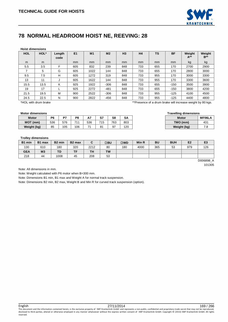
TECHNICAL GUIDE FOR HOISTS
English 27/11/2014 169 / 266This document and the information contained herein, is the exclusive property of SWF Krantechnik GmbH and represents a non-public, confidential and proprietary trade secret that may not be reproduced,
disclosed to third parties, altered or otherwise employed in any manner whatsoever without the express written consent of SWF Krantechnik GmbH. Copyright © (2013) SWF Krantechnik GmbH. All rights
reserved.
78 NORMAL HEADROOM HOIST NE, REEVING: 28
Hoist dimensions HOL HOL* Length
code E1 M1 M2 H3 H4 TS BF Weight
A** Weight
B**
m m mm mm mm mm mm mm mm kg kg
5.5 3.5 F 605 832 239 848 733 655 170 2700 2900
7 5 G 605 1022 144 848 733 655 170 2800 3000
9.5 7.5 H 605 1272 319 848 733 955 170 3000 3300
13 11 J 605 1622 144 848 733 955 170 3300 3600
15.5 13.5 K 925 1922 -306 848 733 655 -150 3500 3900
19 17 L 925 2272 -481 848 733 655 -150 3800 4200
21.5 19.5 M 900 2522 -306 848 733 955 -125 4100 4500
24.5 22.5 N 900 2822 -456 848 733 955 -125 4400 4800
*HOL with drum brake **Presence of a drum brake will increase weight by 80 kgs.
Motor dimensions Travelling dimensions
Motor P6 P7 P8 A7 S7 S8 SA Motor MF06LA MOT (mm) 536 576 711 536 715 763 803 TMO (mm) 431
Weight (kg) 85 105 106 71 81 97 120 Weight (kg) 7.8
Trolley dimensions B1 min B1 max B2 min B2 max C ∅∅∅∅BU ∅∅∅∅WD Min R BU BUH E2 E3
130 610 180 320 2212 80 180 4000 365 53 979 126
GEA M3 TD TF TH TW
218 44 1008 45 208 53
D006898_A 101305
Note: All dimensions in mm. Note: Weight calculated with P6 motor when B=300 mm. Note: Dimensions B1 min, B1 max and Weight A for normal track suspension. Note: Dimensions B2 min, B2 max, Weight B and Min R for curved track suspension (option).

TECHNICAL GUIDE FOR HOISTS
English 27/11/2014 170 / 266This document and the information contained herein, is the exclusive property of SWF Krantechnik GmbH and represents a non-public, confidential and proprietary trade secret that may not be reproduced,
disclosed to third parties, altered or otherwise employed in any manner whatsoever without the express written consent of SWF Krantechnik GmbH. Copyright © (2013) SWF Krantechnik GmbH. All rights
reserved.
Normal Headroom Hoist NE, REEVING: 28 Note: For hoists with Solo electric provisions and a hoisting inverter, a special cubicle layout is required. Please consult the factory. Note: Detail view A for normal track suspension. Detail view B for curved track suspension (option). Note: X points the location for an auxiliary electrical cubicle.

TECHNICAL GUIDE FOR HOISTS
English 27/11/2014 171 / 266This document and the information contained herein, is the exclusive property of SWF Krantechnik GmbH and represents a non-public, confidential and proprietary trade secret that may not be reproduced,
disclosed to third parties, altered or otherwise employed in any manner whatsoever without the express written consent of SWF Krantechnik GmbH. Copyright © (2013) SWF Krantechnik GmbH. All rights
reserved.
FIXED HOIST

TECHNICAL GUIDE FOR HOISTS
English 27/11/2014 172 / 266This document and the information contained herein, is the exclusive property of SWF Krantechnik GmbH and represents a non-public, confidential and proprietary trade secret that may not be reproduced,
disclosed to third parties, altered or otherwise employed in any manner whatsoever without the express written consent of SWF Krantechnik GmbH. Copyright © (2013) SWF Krantechnik GmbH. All rights
reserved.

TECHNICAL GUIDE FOR HOISTS
English 27/11/2014 173 / 266This document and the information contained herein, is the exclusive property of SWF Krantechnik GmbH and represents a non-public, confidential and proprietary trade secret that may not be reproduced,
disclosed to third parties, altered or otherwise employed in any manner whatsoever without the express written consent of SWF Krantechnik GmbH. Copyright © (2013) SWF Krantechnik GmbH. All rights
reserved.
79 FIXED HOIST NB, REEVING: 02
Hoist dimensions HOL Length M1 H2 H3 H3* R Weight
m code mm mm mm mm mm kg
12 A 326 90 448 463 400 125
19 C 456 144 448 463 530 135
Motor dimensions
Motor P1 P2 P3 A3 S3 MOT (mm) 386 446 476 446 526
Weight (kg) 21 31 35 32 28
Trolley dimensions
C ∅∅∅∅F E3 F1 F3 GEA H1 H4 M2 RO TH
195 18 78 100 100 110 127 391 37 25 395 D002071_A
062131 Note: All dimensions in mm. Note: Weight calculated with P1 motor. * Please, disregard the dimension H3*.

TECHNICAL GUIDE FOR HOISTS
English 27/11/2014 174 / 266This document and the information contained herein, is the exclusive property of SWF Krantechnik GmbH and represents a non-public, confidential and proprietary trade secret that may not be reproduced,
disclosed to third parties, altered or otherwise employed in any manner whatsoever without the express written consent of SWF Krantechnik GmbH. Copyright © (2013) SWF Krantechnik GmbH. All rights
reserved.
Fixed Hoist NB, REEVING: 02

TECHNICAL GUIDE FOR HOISTS
English 27/11/2014 175 / 266This document and the information contained herein, is the exclusive property of SWF Krantechnik GmbH and represents a non-public, confidential and proprietary trade secret that may not be reproduced,
disclosed to third parties, altered or otherwise employed in any manner whatsoever without the express written consent of SWF Krantechnik GmbH. Copyright © (2013) SWF Krantechnik GmbH. All rights
reserved.
80 FIXED HOIST NB, REEVING: 04
Hoist dimensions HOL Length M1 H2 H3 H3* R Weight
m code mm mm mm mm mm kg
6 A 326 45 461 476 400 130
9.5 C 456 72 461 476 530 140
Motor dimensions
Motor P1 P2 P3 A3 S3 MOT (mm) 386 446 476 446 526
Weight (kg) 21 31 35 32 28
Trolley dimensions
C ∅∅∅∅F E3 F1 F3 GEA H1 H4 M2 RO TH
145 18 78 113 100 110 182 378 37 25 395 D002078_A
062132 Note: All dimensions in mm. Note: Weight calculated with P1 motor. * Please, disregard the dimension H3*.
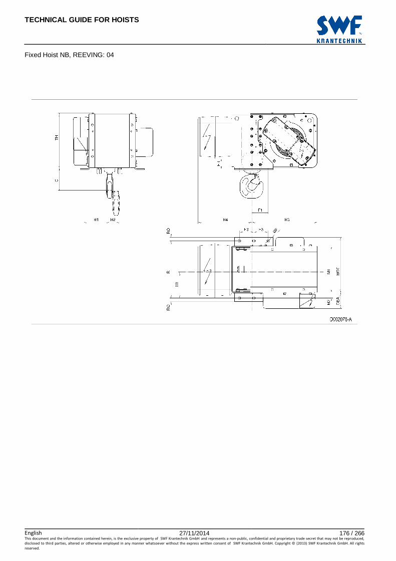
TECHNICAL GUIDE FOR HOISTS
English 27/11/2014 176 / 266This document and the information contained herein, is the exclusive property of SWF Krantechnik GmbH and represents a non-public, confidential and proprietary trade secret that may not be reproduced,
disclosed to third parties, altered or otherwise employed in any manner whatsoever without the express written consent of SWF Krantechnik GmbH. Copyright © (2013) SWF Krantechnik GmbH. All rights
reserved.
Fixed Hoist NB, REEVING: 04
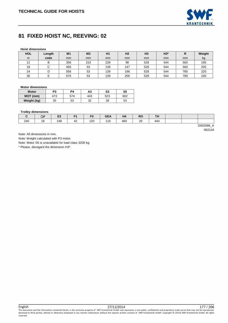
TECHNICAL GUIDE FOR HOISTS
English 27/11/2014 177 / 266This document and the information contained herein, is the exclusive property of SWF Krantechnik GmbH and represents a non-public, confidential and proprietary trade secret that may not be reproduced,
disclosed to third parties, altered or otherwise employed in any manner whatsoever without the express written consent of SWF Krantechnik GmbH. Copyright © (2013) SWF Krantechnik GmbH. All rights
reserved.
81 FIXED HOIST NC, REEVING: 02
Hoist dimensions HOL Length M1 M2 H1 H2 H3 H3* R Weight
m code mm mm mm mm mm mm mm kg
12 B 356 153 239 98 528 544 560 195
18 C 456 53 139 147 528 544 560 205
24 D 556 53 139 196 528 544 780 220
30 E 676 53 139 256 528 544 780 240
Motor dimensions
Motor P3 P4 A3 S3 S5 MOT (mm) 473 574 443 523 602
Weight (kg) 35 53 32 28 53
Trolley dimensions
C ∅∅∅∅F E3 F1 F3 GEA H4 RO TH
240 18 148 42 120 116 460 20 444 D002086_A
062134 Note: All dimensions in mm. Note: Weight calculated with P3 motor. Note: Motor S5 is unavailable for load class 3200 kg. * Please, disregard the dimension H3*.
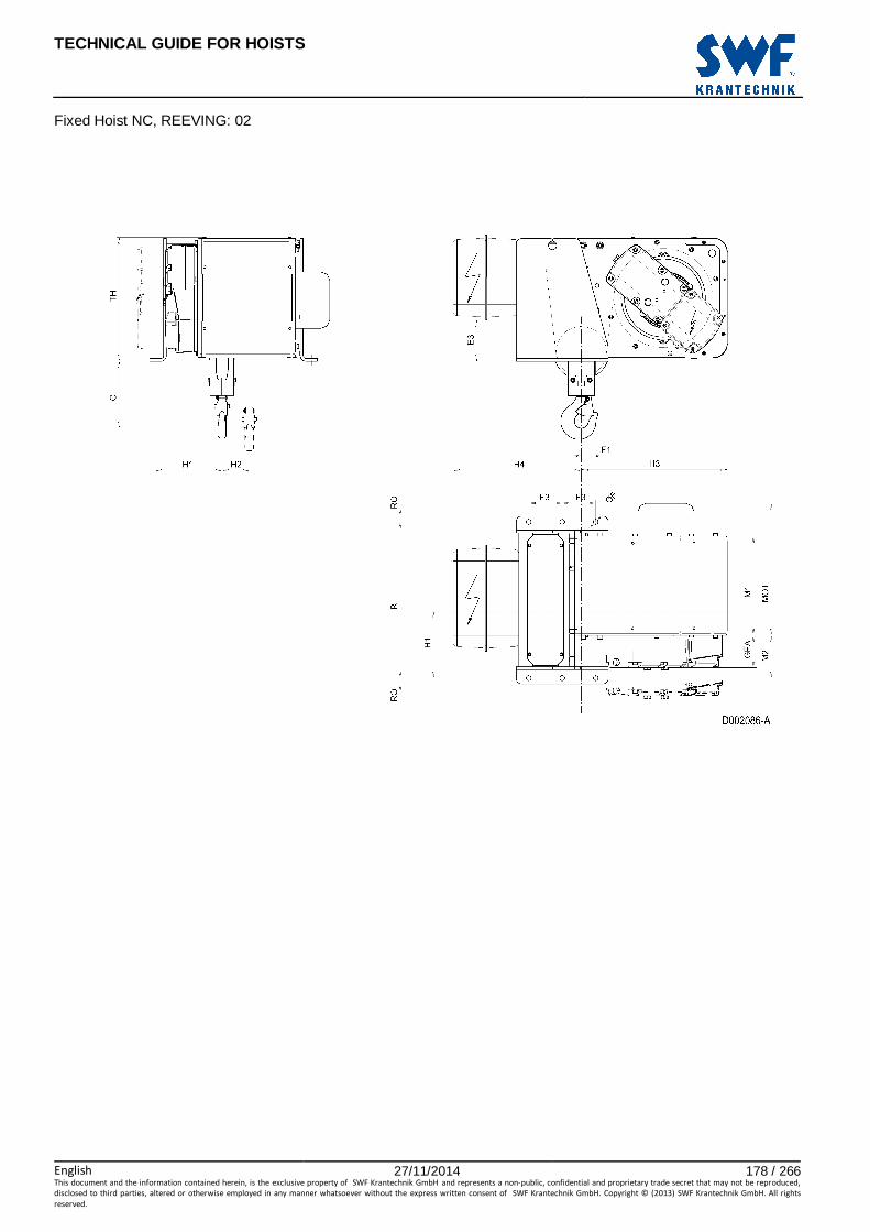
TECHNICAL GUIDE FOR HOISTS
English 27/11/2014 178 / 266This document and the information contained herein, is the exclusive property of SWF Krantechnik GmbH and represents a non-public, confidential and proprietary trade secret that may not be reproduced,
disclosed to third parties, altered or otherwise employed in any manner whatsoever without the express written consent of SWF Krantechnik GmbH. Copyright © (2013) SWF Krantechnik GmbH. All rights
reserved.
Fixed Hoist NC, REEVING: 02

TECHNICAL GUIDE FOR HOISTS
English 27/11/2014 179 / 266This document and the information contained herein, is the exclusive property of SWF Krantechnik GmbH and represents a non-public, confidential and proprietary trade secret that may not be reproduced,
disclosed to third parties, altered or otherwise employed in any manner whatsoever without the express written consent of SWF Krantechnik GmbH. Copyright © (2013) SWF Krantechnik GmbH. All rights
reserved.
82 FIXED HOIST NC, REEVING: 04
Hoist dimensions HOL Length M1 M2 H1 H2 H3 H3* R Weight
m code mm mm mm mm mm mm mm kg
6 B 356 153 320 49 551 567 560 200
9 C 456 53 220 73 551 567 560 210
12 D 556 53 220 97 551 567 780 220
15 E 676 53 220 127 551 567 780 230
Motor dimensions
Motor P3 P4 A3 S3 S5 MOT (mm) 473 574 443 523 602
Weight (kg) 35 53 32 28 53
Trolley dimensions
C1 C2 ∅∅∅∅F E3 F1 F3 GEA H4 RO TH
215 232 18 148 65 120 116 436 20 444 D002091_A
062135 Note: All dimensions in mm. Note: Weight calculated with P3 motor. Note: Motor S5 is unavailable for load class 6300 kg. * Please, disregard the dimension H3*.

TECHNICAL GUIDE FOR HOISTS
English 27/11/2014 180 / 266This document and the information contained herein, is the exclusive property of SWF Krantechnik GmbH and represents a non-public, confidential and proprietary trade secret that may not be reproduced,
disclosed to third parties, altered or otherwise employed in any manner whatsoever without the express written consent of SWF Krantechnik GmbH. Copyright © (2013) SWF Krantechnik GmbH. All rights
reserved.
Fixed Hoist NC, REEVING: 04

TECHNICAL GUIDE FOR HOISTS
English 27/11/2014 181 / 266This document and the information contained herein, is the exclusive property of SWF Krantechnik GmbH and represents a non-public, confidential and proprietary trade secret that may not be reproduced,
disclosed to third parties, altered or otherwise employed in any manner whatsoever without the express written consent of SWF Krantechnik GmbH. Copyright © (2013) SWF Krantechnik GmbH. All rights
reserved.
83 FIXED HOIST ND, REEVING: 02
Hoist dimensions HOL Length M1 M2 H1 H2 H3 H3* R Weight
m code mm mm mm mm mm mm mm kg
18 D 558 196 354 176 621 641 830 430
24 E 678 76 234 235 621 641 830 445
32 F 828 76 234 310 621 641 1170 460
40 G 1018 76 234 405 621 641 1170 480
Motor dimensions
Motor P5 P6 P7 A5 S5 S7 MOT (mm) 578 578 618 498 606 757
Weight (kg) 58 85 105 45 53 81
Trolley dimensions
C ∅∅∅∅F E3 F1 F3 GEA H4 RO TH
366 18 80 140 175 143 543 25 537 D002111_A
062189 Note: All dimensions in mm. Note: Weight calculated with P5 motor. Note: Motor S7 is unavailable for load class 6300 kg. * Please, disregard the dimension H3*.

TECHNICAL GUIDE FOR HOISTS
English 27/11/2014 182 / 266This document and the information contained herein, is the exclusive property of SWF Krantechnik GmbH and represents a non-public, confidential and proprietary trade secret that may not be reproduced,
disclosed to third parties, altered or otherwise employed in any manner whatsoever without the express written consent of SWF Krantechnik GmbH. Copyright © (2013) SWF Krantechnik GmbH. All rights
reserved.
Fixed Hoist ND, REEVING: 02

TECHNICAL GUIDE FOR HOISTS
English 27/11/2014 183 / 266This document and the information contained herein, is the exclusive property of SWF Krantechnik GmbH and represents a non-public, confidential and proprietary trade secret that may not be reproduced,
disclosed to third parties, altered or otherwise employed in any manner whatsoever without the express written consent of SWF Krantechnik GmbH. Copyright © (2013) SWF Krantechnik GmbH. All rights
reserved.
84 FIXED HOIST ND, REEVING: 04
Hoist dimensions HOL Length M1 M2 H1 H2 H3 H3* R Weight
m code mm mm mm mm mm mm mm kg
9 D 558 196 434 88 645 665 830 445
12 E 678 76 314 118 645 665 830 460
16 F 828 76 314 156 645 665 1170 480
20 G 1018 76 314 204 645 665 1170 500
Motor dimensions
Motor P5 P6 P7 A5 S5 S7 MOT (mm) 578 578 618 498 606 757
Weight (kg) 58 85 105 45 53 81
Trolley dimensions
C1 C2 ∅∅∅∅F E3 F1 F3 GEA H4 RO TH
310 367 18 80 168 175 143 516 25 537 D002116_A
062190 Note: All dimensions in mm. Note: Weight calculated with P5 motor. Note: Motor S7 is unavailable for load class 12500 kg. * Please, disregard the dimension H3*.
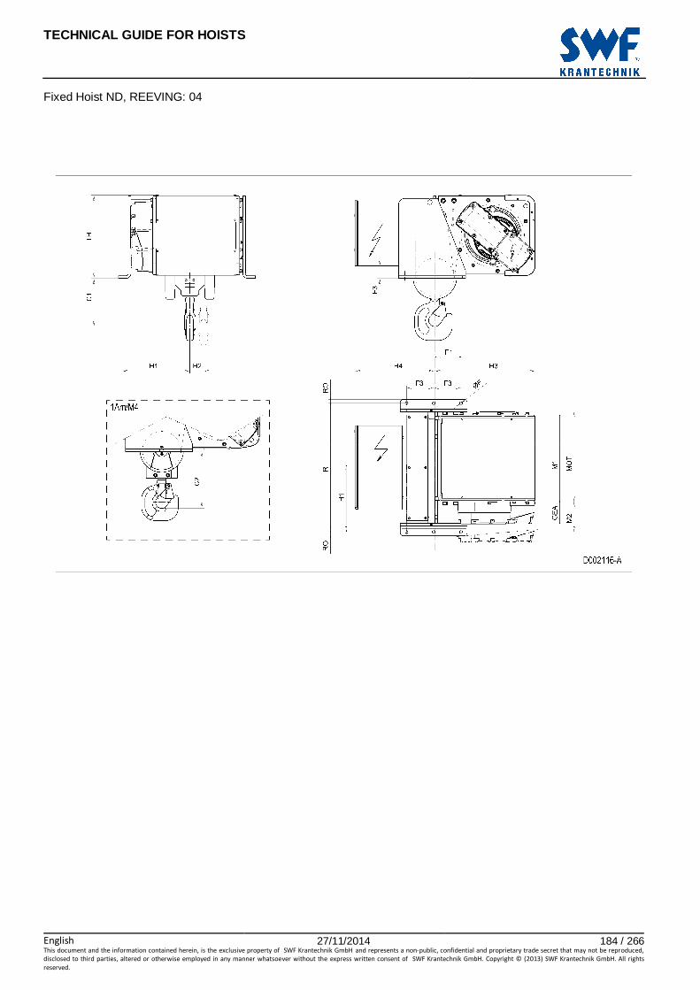
TECHNICAL GUIDE FOR HOISTS
English 27/11/2014 184 / 266This document and the information contained herein, is the exclusive property of SWF Krantechnik GmbH and represents a non-public, confidential and proprietary trade secret that may not be reproduced,
disclosed to third parties, altered or otherwise employed in any manner whatsoever without the express written consent of SWF Krantechnik GmbH. Copyright © (2013) SWF Krantechnik GmbH. All rights
reserved.
Fixed Hoist ND, REEVING: 04

TECHNICAL GUIDE FOR HOISTS
English 27/11/2014 185 / 266This document and the information contained herein, is the exclusive property of SWF Krantechnik GmbH and represents a non-public, confidential and proprietary trade secret that may not be reproduced,
disclosed to third parties, altered or otherwise employed in any manner whatsoever without the express written consent of SWF Krantechnik GmbH. Copyright © (2013) SWF Krantechnik GmbH. All rights
reserved.
85 FIXED HOIST ND, REEVING: 06
Hoist dimensions HOL Length M1 M2 Min R H1 H2 H3 H3* Weight
m code mm mm mm mm mm mm mm kg
6 D 558 548 1200 515 53 605 625 585
8 E 678 628 1400 595 78 605 625 625
10 F 828 778 1700 745 98 605 625 675
13 G 1018 888 2000 855 132 605 625 735
Motor dimensions
Motor P5 P6 P7 A5 S5 S7 MOT (mm) 578 578 618 498 606 757
Weight (kg) 58 85 105 45 53 81
Trolley dimensions
C ∅∅∅∅F E1 E3 E8 F1 F2 F3 GEA H4 RO TH
693 18 406 100 130 200 440 70 143 270 70 527
D007242_A 126313
Note: All dimensions in mm. Note: Weight calculated with P5 motor. Note: H1, M2 and weight calculated with Min R. Note: Standard rail gauges: 1200, 1400, 1700, 2000 and 2400. * Please, disregard the dimension H3*.

TECHNICAL GUIDE FOR HOISTS
English 27/11/2014 186 / 266This document and the information contained herein, is the exclusive property of SWF Krantechnik GmbH and represents a non-public, confidential and proprietary trade secret that may not be reproduced,
disclosed to third parties, altered or otherwise employed in any manner whatsoever without the express written consent of SWF Krantechnik GmbH. Copyright © (2013) SWF Krantechnik GmbH. All rights
reserved.
Fixed Hoist ND, REEVING: 06

TECHNICAL GUIDE FOR HOISTS
English 27/11/2014 187 / 266This document and the information contained herein, is the exclusive property of SWF Krantechnik GmbH and represents a non-public, confidential and proprietary trade secret that may not be reproduced,
disclosed to third parties, altered or otherwise employed in any manner whatsoever without the express written consent of SWF Krantechnik GmbH. Copyright © (2013) SWF Krantechnik GmbH. All rights
reserved.
86 FIXED HOIST ND, REEVING: 08
Hoist dimensions HOL Length M1 M2 Min R H1 H2 H3 H3* Weight
m code mm mm mm mm mm mm mm kg
4.5 D 558 548 1200 515 44 605 625 600
6 E 678 628 1400 595 53 605 625 635
8 F 828 778 1700 745 76 605 625 690
10 G 1018 888 2000 855 98 605 625 750
Motor dimensions
Motor P5 P6 P7 A5 S5 S7 MOT (mm) 578 578 618 498 606 757
Weight (kg) 58 85 105 45 53 81
Trolley dimensions
C ∅∅∅∅F E1 E3 E8 F1 F2 F3 GEA H4 RO TH
693 18 406 100 130 200 440 70 143 270 70 527
D007243_A 126314
Note: All dimensions in mm. Note: Weight calculated with P5 motor. Note: H1, M2 and weight calculated with Min R. Note: Standard rail gauges: 1200, 1400, 1700, 2000 and 2400. * Please, disregard the dimension H3*.

TECHNICAL GUIDE FOR HOISTS
English 27/11/2014 188 / 266This document and the information contained herein, is the exclusive property of SWF Krantechnik GmbH and represents a non-public, confidential and proprietary trade secret that may not be reproduced,
disclosed to third parties, altered or otherwise employed in any manner whatsoever without the express written consent of SWF Krantechnik GmbH. Copyright © (2013) SWF Krantechnik GmbH. All rights
reserved.
Fixed Hoist ND, REEVING: 08

TECHNICAL GUIDE FOR HOISTS
English 27/11/2014 189 / 266This document and the information contained herein, is the exclusive property of SWF Krantechnik GmbH and represents a non-public, confidential and proprietary trade secret that may not be reproduced,
disclosed to third parties, altered or otherwise employed in any manner whatsoever without the express written consent of SWF Krantechnik GmbH. Copyright © (2013) SWF Krantechnik GmbH. All rights
reserved.
87 FIXED HOIST ND, REEVING: 22
Hoist dimensions HOL Length M1 M2 Min R BRA H3 H3* Weight
m code mm mm mm mm mm mm kg
8.5 D 558 321 1200 - 595 615 505
13 E 678 261 1200 - 595 615 530
18 F 828 186 1200 - 595 615 555
25 G 1018 91 1200 - 595 615 590
33.5 H 1268 216 1700 128 595 615 670
46 J 1618 191 2000 128 595 615 755
Motor dimensions
Motor P5 P6 P7 A5 S5 S7 MOT (mm) 578 578 618 498 606 757
Weight (kg) 58 85 105 45 53 81
Trolley dimensions
C ∅∅∅∅F E1 E3 E8 F1 F2 F3 GEA H4 RO TH
523 18 406 100 130 155 440 70 143 315 70 527
D007244_A 126316
Note: All dimensions in mm. Note: Weight calculated with P5 motor. Note: M2 and weight calculated with Min R. Note: Standard rail gauges: 1200, 1700 and 2000. Note: Gear brake as standard brake for drum lengths H and J. * Please, disregard the dimension H3*.
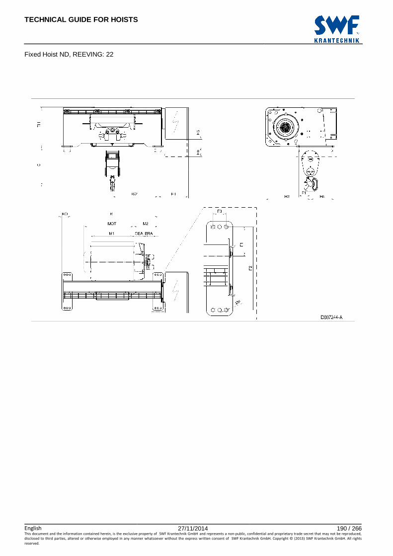
TECHNICAL GUIDE FOR HOISTS
English 27/11/2014 190 / 266This document and the information contained herein, is the exclusive property of SWF Krantechnik GmbH and represents a non-public, confidential and proprietary trade secret that may not be reproduced,
disclosed to third parties, altered or otherwise employed in any manner whatsoever without the express written consent of SWF Krantechnik GmbH. Copyright © (2013) SWF Krantechnik GmbH. All rights
reserved.
Fixed Hoist ND, REEVING: 22

TECHNICAL GUIDE FOR HOISTS
English 27/11/2014 191 / 266This document and the information contained herein, is the exclusive property of SWF Krantechnik GmbH and represents a non-public, confidential and proprietary trade secret that may not be reproduced,
disclosed to third parties, altered or otherwise employed in any manner whatsoever without the express written consent of SWF Krantechnik GmbH. Copyright © (2013) SWF Krantechnik GmbH. All rights
reserved.
88 FIXED HOIST ND, REEVING: 24
Hoist dimensions HOL Length M1 M2 Min R BRA H3 H3* Weight
m code mm mm mm mm mm mm kg
4 D 558 321 1200 - 595 615 570
6.5 E 678 261 1200 - 595 615 590
9 F 828 186 1200 - 595 615 620
12.5 G 1018 91 1200 - 595 615 655
16.5 H 1268 216 1700 128 595 615 735
23 J 1618 191 2000 128 595 615 815
Motor dimensions
Motor P5 P6 P7 A5 S5 S7 MOT (mm) 578 578 618 498 606 757
Weight (kg) 58 85 105 45 53 81
Trolley dimensions
C ∅∅∅∅F E1 E3 E8 F1 F2 F3 GEA H4 RO TH
688 18 406 100 130 155 440 70 143 315 70 527
D007245_A 126317
Note: All dimensions in mm. Note: Weight calculated with P5 motor. Note: M2 and weight calculated with Min R. Note: Standard rail gauges: 1200, 1700 and 2000. Note: Gear brake as standard brake for drum lengths H and J. * Please, disregard the dimension H3*.

TECHNICAL GUIDE FOR HOISTS
English 27/11/2014 192 / 266This document and the information contained herein, is the exclusive property of SWF Krantechnik GmbH and represents a non-public, confidential and proprietary trade secret that may not be reproduced,
disclosed to third parties, altered or otherwise employed in any manner whatsoever without the express written consent of SWF Krantechnik GmbH. Copyright © (2013) SWF Krantechnik GmbH. All rights
reserved.
Fixed Hoist ND, REEVING: 24

TECHNICAL GUIDE FOR HOISTS
English 27/11/2014 193 / 266This document and the information contained herein, is the exclusive property of SWF Krantechnik GmbH and represents a non-public, confidential and proprietary trade secret that may not be reproduced,
disclosed to third parties, altered or otherwise employed in any manner whatsoever without the express written consent of SWF Krantechnik GmbH. Copyright © (2013) SWF Krantechnik GmbH. All rights
reserved.
89 FIXED HOIST ND, REEVING: 26
Hoist dimensions HOL Length M1 M2 Min R BRA H3 H3* Weight
m code mm mm mm mm mm mm kg
4 E 678 261 1200 - 595 615 600
6 F 828 186 1200 - 595 615 625
8 G 1018 91 1200 - 595 615 665
11 H 1268 216 1700 128 595 615 745
15 J 1618 191 2000 128 595 615 830
Motor dimensions
Motor P5 P6 P7 A5 S5 S7 MOT (mm) 578 578 618 498 606 757
Weight (kg) 58 85 105 45 53 81
Trolley dimensions
C ∅∅∅∅F E1 E3 E8 F1 F2 F3 GEA H4 RO TH
688 18 406 100 130 200 440 70 143 270 70 527
D007246_A 126318
Note: All dimensions in mm. Note: Weight calculated with P5 motor. Note: M2 and weight calculated with Min R. Note: Standard rail gauges: 1200, 1700 and 2000. Note: Gear brake as standard brake for drum lengths H and J. * Please, disregard the dimension H3*.

TECHNICAL GUIDE FOR HOISTS
English 27/11/2014 194 / 266This document and the information contained herein, is the exclusive property of SWF Krantechnik GmbH and represents a non-public, confidential and proprietary trade secret that may not be reproduced,
disclosed to third parties, altered or otherwise employed in any manner whatsoever without the express written consent of SWF Krantechnik GmbH. Copyright © (2013) SWF Krantechnik GmbH. All rights
reserved.
Fixed Hoist ND, REEVING: 26

TECHNICAL GUIDE FOR HOISTS
English 27/11/2014 195 / 266This document and the information contained herein, is the exclusive property of SWF Krantechnik GmbH and represents a non-public, confidential and proprietary trade secret that may not be reproduced,
disclosed to third parties, altered or otherwise employed in any manner whatsoever without the express written consent of SWF Krantechnik GmbH. Copyright © (2013) SWF Krantechnik GmbH. All rights
reserved.
90 FIXED HOIST ND, REEVING: 28
Hoist dimensions HOL Length M1 M2 Min R BRA H3 H3* Weight
m code mm mm mm mm mm mm kg
4.5 F 828 186 1200 - 595 615 640
6 G 1018 91 1200 - 595 615 675
8 H 1268 216 1700 128 595 615 755
11.5 J 1618 191 2000 128 595 615 815
Motor dimensions
Motor P5 P6 P7 A5 S5 S7 MOT (mm) 578 578 618 498 606 757
Weight (kg) 58 85 105 45 53 81
Trolley dimensions
C ∅∅∅∅F E1 E3 E8 F1 F2 F3 GEA H4 RO TH
688 18 406 100 130 200 440 70 143 270 70 527
D007247_A 126319
Note: All dimensions in mm. Note: Weight calculated with P5 motor. Note: M2 and weight calculated with Min R. Note: Standard rail gauges: 1200, 1700 and 2000. Note: Gear brake as standard brake for drum lengths H and J. * Please, disregard the dimension H3*.

TECHNICAL GUIDE FOR HOISTS
English 27/11/2014 196 / 266This document and the information contained herein, is the exclusive property of SWF Krantechnik GmbH and represents a non-public, confidential and proprietary trade secret that may not be reproduced,
disclosed to third parties, altered or otherwise employed in any manner whatsoever without the express written consent of SWF Krantechnik GmbH. Copyright © (2013) SWF Krantechnik GmbH. All rights
reserved.
Fixed Hoist ND, REEVING: 28

TECHNICAL GUIDE FOR HOISTS
English 27/11/2014 197 / 266This document and the information contained herein, is the exclusive property of SWF Krantechnik GmbH and represents a non-public, confidential and proprietary trade secret that may not be reproduced,
disclosed to third parties, altered or otherwise employed in any manner whatsoever without the express written consent of SWF Krantechnik GmbH. Copyright © (2013) SWF Krantechnik GmbH. All rights
reserved.
91 FIXED HOIST NE, REEVING: 02
Hoist dimensions HOL HOL* Length R M1 M2 H1 H2 Weight**
m m code mm mm mm mm mm kg
15.5 10 C 1610 462 760 700 139 1200
21 15.5 D 1610 562 760 700 188 1300
28 22.5 E 1840 682 710 650 251 1300
36 30.5 F 1840 832 710 650 322 1400
47 41.5 G 2350 1022 790 730 421 1500
61 55.5 H 2350 1272 790 730 546 1600
80.5 75 J 2669 1622 750 690 721 1900
97 91.5 K 2669 1922 750 690 868 2000
*HOL with drum brake **Presence of a drum brake will increase weight by 80 kgs.
Motor dimensions
Motor P6 P7 P8 A7 S7 S8 SA MOT (mm) 536 576 711 536 715 763 803
Weight (kg) 85 105 106 71 81 97 120
Trolley dimensions
C ∅∅∅∅F E1 E2 E3 F1 F2 F3 GEA H3 M3 RO
754 18 455 960 126 158.5 320 60 218 871 44 50
TH 769
D006936_A 102573
Note: All dimensions in mm. Note: Weight calculated with P6 motor. Note: X points the location for an auxiliary electrical cubicle.

TECHNICAL GUIDE FOR HOISTS
English 27/11/2014 198 / 266This document and the information contained herein, is the exclusive property of SWF Krantechnik GmbH and represents a non-public, confidential and proprietary trade secret that may not be reproduced,
disclosed to third parties, altered or otherwise employed in any manner whatsoever without the express written consent of SWF Krantechnik GmbH. Copyright © (2013) SWF Krantechnik GmbH. All rights
reserved.
Fixed Hoist NE, REEVING: 02
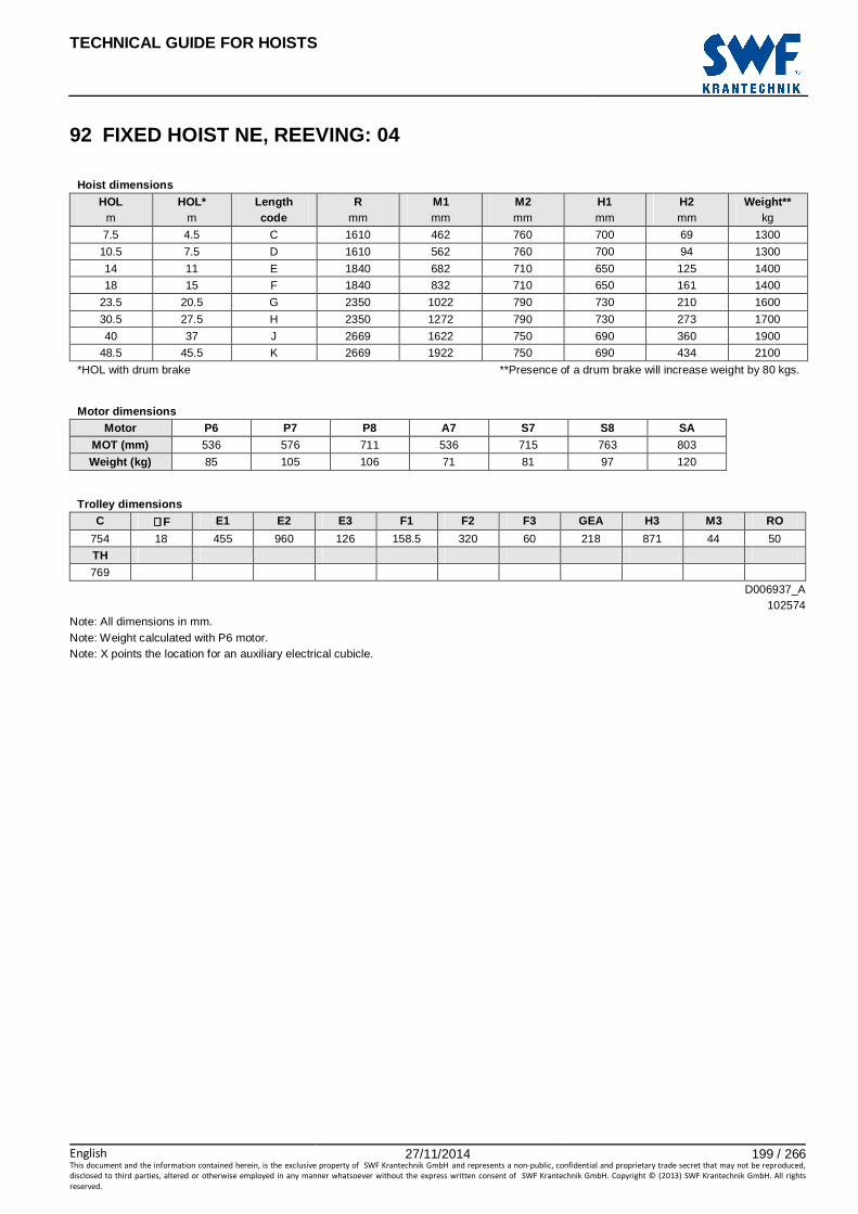
TECHNICAL GUIDE FOR HOISTS
English 27/11/2014 199 / 266This document and the information contained herein, is the exclusive property of SWF Krantechnik GmbH and represents a non-public, confidential and proprietary trade secret that may not be reproduced,
disclosed to third parties, altered or otherwise employed in any manner whatsoever without the express written consent of SWF Krantechnik GmbH. Copyright © (2013) SWF Krantechnik GmbH. All rights
reserved.
92 FIXED HOIST NE, REEVING: 04
Hoist dimensions HOL HOL* Length R M1 M2 H1 H2 Weight**
m m code mm mm mm mm mm kg
7.5 4.5 C 1610 462 760 700 69 1300
10.5 7.5 D 1610 562 760 700 94 1300
14 11 E 1840 682 710 650 125 1400
18 15 F 1840 832 710 650 161 1400
23.5 20.5 G 2350 1022 790 730 210 1600
30.5 27.5 H 2350 1272 790 730 273 1700
40 37 J 2669 1622 750 690 360 1900
48.5 45.5 K 2669 1922 750 690 434 2100
*HOL with drum brake **Presence of a drum brake will increase weight by 80 kgs.
Motor dimensions
Motor P6 P7 P8 A7 S7 S8 SA MOT (mm) 536 576 711 536 715 763 803
Weight (kg) 85 105 106 71 81 97 120
Trolley dimensions
C ∅∅∅∅F E1 E2 E3 F1 F2 F3 GEA H3 M3 RO
754 18 455 960 126 158.5 320 60 218 871 44 50
TH 769
D006937_A 102574
Note: All dimensions in mm. Note: Weight calculated with P6 motor. Note: X points the location for an auxiliary electrical cubicle.

TECHNICAL GUIDE FOR HOISTS
English 27/11/2014 200 / 266This document and the information contained herein, is the exclusive property of SWF Krantechnik GmbH and represents a non-public, confidential and proprietary trade secret that may not be reproduced,
disclosed to third parties, altered or otherwise employed in any manner whatsoever without the express written consent of SWF Krantechnik GmbH. Copyright © (2013) SWF Krantechnik GmbH. All rights
reserved.
Fixed Hoist NE, REEVING: 04

TECHNICAL GUIDE FOR HOISTS
English 27/11/2014 201 / 266This document and the information contained herein, is the exclusive property of SWF Krantechnik GmbH and represents a non-public, confidential and proprietary trade secret that may not be reproduced,
disclosed to third parties, altered or otherwise employed in any manner whatsoever without the express written consent of SWF Krantechnik GmbH. Copyright © (2013) SWF Krantechnik GmbH. All rights
reserved.
93 FIXED HOIST NE, REEVING: 06
Hoist dimensions HOL HOL* Length R M1 M2 H1 H2 Weight**
m m code mm mm mm mm mm kg
5 3 C 1610 462 760 700 46 1300
7 5 D 1610 562 760 700 63 1400
9 7 E 1840 682 710 650 84 1500
12 10 F 1840 832 710 650 107 1500
15.5 13.5 G 2350 1022 790 730 140 1600
20 18 H 2350 1272 790 730 182 1800
26.5 24.5 J 2669 1622 750 690 240 2000
32 30 K 2669 1922 750 690 289 2100
*HOL with drum brake **Presence of a drum brake will increase weight by 80 kgs.
Motor dimensions
Motor P6 P7 P8 A7 S7 S8 SA MOT (mm) 536 576 711 536 715 763 803
Weight (kg) 85 105 106 71 81 97 120
Trolley dimensions
C ∅∅∅∅F E1 E2 E3 F1 F2 F3 GEA H3 M3 RO
873 18 455 960 126 158.5 320 60 218 871 44 50
TH 769
D006938_A 102575
Note: All dimensions in mm. Note: Weight calculated with P6 motor. Note: X points the location for an auxiliary electrical cubicle.

TECHNICAL GUIDE FOR HOISTS
English 27/11/2014 202 / 266This document and the information contained herein, is the exclusive property of SWF Krantechnik GmbH and represents a non-public, confidential and proprietary trade secret that may not be reproduced,
disclosed to third parties, altered or otherwise employed in any manner whatsoever without the express written consent of SWF Krantechnik GmbH. Copyright © (2013) SWF Krantechnik GmbH. All rights
reserved.
Fixed Hoist NE, REEVING: 06

TECHNICAL GUIDE FOR HOISTS
English 27/11/2014 203 / 266This document and the information contained herein, is the exclusive property of SWF Krantechnik GmbH and represents a non-public, confidential and proprietary trade secret that may not be reproduced,
disclosed to third parties, altered or otherwise employed in any manner whatsoever without the express written consent of SWF Krantechnik GmbH. Copyright © (2013) SWF Krantechnik GmbH. All rights
reserved.
94 FIXED HOIST NE, REEVING: 08
Hoist dimensions HOL HOL* Length R M1 M2 H1 H2 Weight**
m m code mm mm mm mm mm kg
7 5.5 E 1840 682 710 650 63 1500
9 7.5 F 1840 832 710 650 81 1600
11.5 10 G 2350 1022 790 730 105 1700
15 13.5 H 2350 1272 790 730 137 1800
20 18.5 J 2669 1622 750 690 180 2100
24 22.5 K 2669 1922 750 690 217 2200
*HOL with drum brake **Presence of a drum brake will increase weight by 80 kgs.
Motor dimensions
Motor P6 P7 P8 A7 S7 S8 SA MOT (mm) 536 576 711 536 715 763 803
Weight (kg) 85 105 106 71 81 97 120
Trolley dimensions
C ∅∅∅∅F E1 E2 E3 F1 F2 F3 GEA H3 M3 RO
1096 18 455 960 126 158.5 320 60 218 871 44 50
TH 769
D006939_A 102576
Note: All dimensions in mm. Note: Weight calculated with P6 motor. Note: X points the location for an auxiliary electrical cubicle.

TECHNICAL GUIDE FOR HOISTS
English 27/11/2014 204 / 266This document and the information contained herein, is the exclusive property of SWF Krantechnik GmbH and represents a non-public, confidential and proprietary trade secret that may not be reproduced,
disclosed to third parties, altered or otherwise employed in any manner whatsoever without the express written consent of SWF Krantechnik GmbH. Copyright © (2013) SWF Krantechnik GmbH. All rights
reserved.
Fixed Hoist NE, REEVING: 08
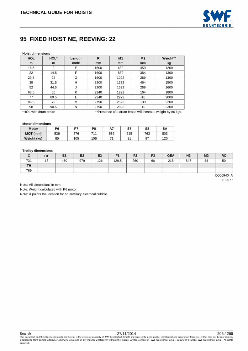
TECHNICAL GUIDE FOR HOISTS
English 27/11/2014 205 / 266This document and the information contained herein, is the exclusive property of SWF Krantechnik GmbH and represents a non-public, confidential and proprietary trade secret that may not be reproduced,
disclosed to third parties, altered or otherwise employed in any manner whatsoever without the express written consent of SWF Krantechnik GmbH. Copyright © (2013) SWF Krantechnik GmbH. All rights
reserved.
95 FIXED HOIST NE, REEVING: 22
Hoist dimensions HOL HOL* Length R M1 M2 Weight**
m m code mm mm mm kg
16.5 9 E 1600 682 459 1200
22 14.5 F 1600 832 384 1300
29.5 22 G 1600 1022 289 1300
39 31.5 H 2200 1272 464 1500
52 44.5 J 2200 1622 289 1600
63.5 56 K 2240 1922 164 1800
77 69.5 L 2240 2272 -10 2000
86.5 79 M 2790 2522 139 2200
98 90.5 N 2790 2822 -10 2300
*HOL with drum brake **Presence of a drum brake will increase weight by 80 kgs.
Motor dimensions
Motor P6 P7 P8 A7 S7 S8 SA MOT (mm) 536 576 711 536 715 763 803
Weight (kg) 85 105 106 71 81 97 120
Trolley dimensions
C ∅∅∅∅F E1 E2 E3 F1 F2 F3 GEA H3 M3 RO
731 18 460 979 126 129.5 260 60 218 847 44 50
TH 769
D006940_A 102577
Note: All dimensions in mm. Note: Weight calculated with P6 motor. Note: X points the location for an auxiliary electrical cubicle.
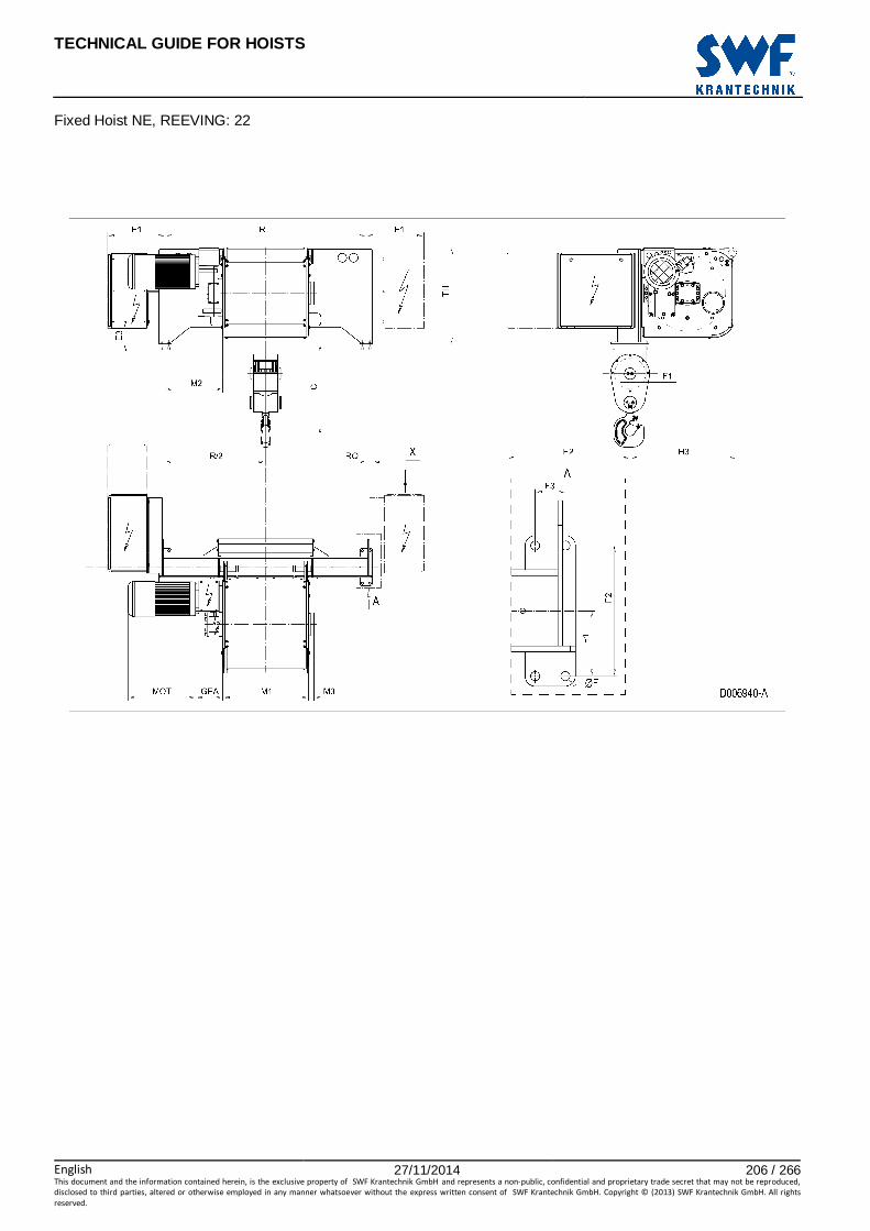
TECHNICAL GUIDE FOR HOISTS
English 27/11/2014 206 / 266This document and the information contained herein, is the exclusive property of SWF Krantechnik GmbH and represents a non-public, confidential and proprietary trade secret that may not be reproduced,
disclosed to third parties, altered or otherwise employed in any manner whatsoever without the express written consent of SWF Krantechnik GmbH. Copyright © (2013) SWF Krantechnik GmbH. All rights
reserved.
Fixed Hoist NE, REEVING: 22

TECHNICAL GUIDE FOR HOISTS
English 27/11/2014 207 / 266This document and the information contained herein, is the exclusive property of SWF Krantechnik GmbH and represents a non-public, confidential and proprietary trade secret that may not be reproduced,
disclosed to third parties, altered or otherwise employed in any manner whatsoever without the express written consent of SWF Krantechnik GmbH. Copyright © (2013) SWF Krantechnik GmbH. All rights
reserved.
96 FIXED HOIST NE, REEVING: 24
Hoist dimensions HOL HOL* Length R M1 M2 Weight**
m m code mm mm mm kg
8 4 E 1600 682 459 1300
11 7 F 1600 832 384 1300
14.5 10.5 G 1600 1022 289 1400
19.5 15.5 H 2200 1272 464 1600
26 22 J 2200 1622 289 1700
31.5 27.5 K 2240 1922 164 1900
38.5 34.5 L 2240 2272 -10 2000
43 39 M 2790 2522 139 2200
49 45 N 2790 2822 -10 2400
*HOL with drum brake **Presence of a drum brake will increase weight by 80 kgs.
Motor dimensions
Motor P6 P7 P8 A7 S7 S8 SA MOT (mm) 536 576 711 536 715 763 803
Weight (kg) 85 105 106 71 81 97 120
Trolley dimensions
C ∅∅∅∅F E1 E2 E3 F1 F2 F3 GEA H3 M3 RO
1040 18 460 979 126 129.5 260 60 218 847 44 50
TH 769
D006941_A 102578
Note: All dimensions in mm. Note: Weight calculated with P6 motor. Note: X points the location for an auxiliary electrical cubicle.

TECHNICAL GUIDE FOR HOISTS
English 27/11/2014 208 / 266This document and the information contained herein, is the exclusive property of SWF Krantechnik GmbH and represents a non-public, confidential and proprietary trade secret that may not be reproduced,
disclosed to third parties, altered or otherwise employed in any manner whatsoever without the express written consent of SWF Krantechnik GmbH. Copyright © (2013) SWF Krantechnik GmbH. All rights
reserved.
Fixed Hoist NE, REEVING: 24

TECHNICAL GUIDE FOR HOISTS
English 27/11/2014 209 / 266This document and the information contained herein, is the exclusive property of SWF Krantechnik GmbH and represents a non-public, confidential and proprietary trade secret that may not be reproduced,
disclosed to third parties, altered or otherwise employed in any manner whatsoever without the express written consent of SWF Krantechnik GmbH. Copyright © (2013) SWF Krantechnik GmbH. All rights
reserved.
97 FIXED HOIST NE, REEVING: 26
Hoist dimensions HOL HOL* Length R M1 M2 Weight**
m m code mm mm mm kg
5.5 3 E 1600 682 459 1400
7 4.5 F 1600 832 384 1400
9.5 7 G 1600 1022 289 1500
13 10.5 H 2200 1272 464 1700
17 14.5 J 2200 1622 289 1800
21 18.5 K 2240 1922 164 1900
25.5 23 L 2240 2272 -10 2100
28.5 26 M 2790 2522 139 2300
32.5 30 N 2790 2822 -10 2400
*HOL with drum brake **Presence of a drum brake will increase weight by 80 kgs.
Motor dimensions
Motor P6 P7 P8 A7 S7 S8 SA MOT (mm) 536 576 711 536 715 763 803
Weight (kg) 85 105 106 71 81 97 120
Trolley dimensions
C ∅∅∅∅F E1 E2 E3 F1 F2 F3 GEA H3 M3 RO
1079 18 460 979 126 129.5 260 60 218 847 44 50
TH 769
D006942_A 102579
Note: All dimensions in mm. Note: Weight calculated with P6 motor. Note: X points the location for an auxiliary electrical cubicle.

TECHNICAL GUIDE FOR HOISTS
English 27/11/2014 210 / 266This document and the information contained herein, is the exclusive property of SWF Krantechnik GmbH and represents a non-public, confidential and proprietary trade secret that may not be reproduced,
disclosed to third parties, altered or otherwise employed in any manner whatsoever without the express written consent of SWF Krantechnik GmbH. Copyright © (2013) SWF Krantechnik GmbH. All rights
reserved.
Fixed Hoist NE, REEVING: 26

TECHNICAL GUIDE FOR HOISTS
English 27/11/2014 211 / 266This document and the information contained herein, is the exclusive property of SWF Krantechnik GmbH and represents a non-public, confidential and proprietary trade secret that may not be reproduced,
disclosed to third parties, altered or otherwise employed in any manner whatsoever without the express written consent of SWF Krantechnik GmbH. Copyright © (2013) SWF Krantechnik GmbH. All rights
reserved.
98 FIXED HOIST NE, REEVING: 28
Hoist dimensions HOL HOL* Length R M1 M2 Weight**
m m code mm mm mm kg
5.5 3.5 F 1600 832 384 1500
7 5 G 1600 1022 289 1600
9.5 7.5 H 2200 1272 464 1800
13 11 J 2200 1622 289 1900
15.5 13.5 K 2240 1922 164 2100
19 17 L 2240 2272 -10 2200
21.5 19.5 M 2790 2522 139 2400
24.5 22.5 N 2790 2822 -10 2600
*HOL with drum brake **Presence of a drum brake will increase weight by 80 kgs.
Motor dimensions
Motor P6 P7 P8 A7 S7 S8 SA MOT (mm) 536 576 711 536 715 763 803
Weight (kg) 85 105 106 71 81 97 120
Trolley dimensions
C ∅∅∅∅F E1 E2 E3 F1 F2 F3 GEA H3 M3 RO
1206 18 460 979 126 129.5 260 60 218 847 44 50
TH 769
D006943_A 102580
Note: All dimensions in mm. Note: Weight calculated with P6 motor. Note: X points the location for an auxiliary electrical cubicle.

TECHNICAL GUIDE FOR HOISTS
English 27/11/2014 212 / 266This document and the information contained herein, is the exclusive property of SWF Krantechnik GmbH and represents a non-public, confidential and proprietary trade secret that may not be reproduced,
disclosed to third parties, altered or otherwise employed in any manner whatsoever without the express written consent of SWF Krantechnik GmbH. Copyright © (2013) SWF Krantechnik GmbH. All rights
reserved.
Fixed Hoist NE, REEVING: 28

TECHNICAL GUIDE FOR HOISTS
English 27/11/2014 213 / 266This document and the information contained herein, is the exclusive property of SWF Krantechnik GmbH and represents a non-public, confidential and proprietary trade secret that may not be reproduced,
disclosed to third parties, altered or otherwise employed in any manner whatsoever without the express written consent of SWF Krantechnik GmbH. Copyright © (2013) SWF Krantechnik GmbH. All rights
reserved.
99 FIXED HOIST NF, REEVING: 22
Hoist dimensions HOL HOL* Length R M1 M2 Weight**
m m code mm mm mm kg
15.5 9 F 1700 832 434 1400
20.5 14 G 1700 1022 339 1500
27.5 21 H 2400 1272 565 1600
37.5 31 J 2400 1622 389 1800
46 39.5 K 3100 1922 339 2000
55.5 49 L 3100 2272 414 2200
62.5 56 M 3800 2522 840 2400
71 64.5 N 3800 2822 690 2600
*HOL with drum brake **Presence of a drum brake will increase weight by 80 kgs.
Motor dimensions
Motor P6 P7 A7 S7 S8 SA MOT (mm) 536 576 536 715 763 803
Weight (kg) 85 105 71 81 97 120
Trolley dimensions
C ∅∅∅∅F E1 E2 E3 F1 F2 F3 GEA H3 M3 RO
918 18 488 941 122 220 540 70 218 871 44 92
TD TH 272 463
D006944_A 102581
Note: All dimensions in mm. Note: Weight calculated with P6 motors. Note: The larger electrical cubicle is required with P7 motors.

TECHNICAL GUIDE FOR HOISTS
English 27/11/2014 214 / 266This document and the information contained herein, is the exclusive property of SWF Krantechnik GmbH and represents a non-public, confidential and proprietary trade secret that may not be reproduced,
disclosed to third parties, altered or otherwise employed in any manner whatsoever without the express written consent of SWF Krantechnik GmbH. Copyright © (2013) SWF Krantechnik GmbH. All rights
reserved.
Fixed Hoist NF, REEVING: 22
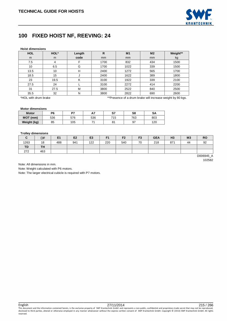
TECHNICAL GUIDE FOR HOISTS
English 27/11/2014 215 / 266This document and the information contained herein, is the exclusive property of SWF Krantechnik GmbH and represents a non-public, confidential and proprietary trade secret that may not be reproduced,
disclosed to third parties, altered or otherwise employed in any manner whatsoever without the express written consent of SWF Krantechnik GmbH. Copyright © (2013) SWF Krantechnik GmbH. All rights
reserved.
100 FIXED HOIST NF, REEVING: 24
Hoist dimensions HOL HOL* Length R M1 M2 Weight**
m m code mm mm mm kg
7.5 4 F 1700 832 434 1500
10 6.5 G 1700 1022 339 1500
13.5 10 H 2400 1272 565 1700
18.5 15 J 2400 1622 389 1800
23 19.5 K 3100 1922 339 2100
27.5 24 L 3100 2272 414 2200
31 27.5 M 3800 2522 840 2500
35.5 32 N 3800 2822 690 2600
*HOL with drum brake **Presence of a drum brake will increase weight by 80 kgs.
Motor dimensions
Motor P6 P7 A7 S7 S8 SA MOT (mm) 536 576 536 715 763 803
Weight (kg) 85 105 71 81 97 120
Trolley dimensions
C ∅∅∅∅F E1 E2 E3 F1 F2 F3 GEA H3 M3 RO
1263 18 488 941 122 220 540 70 218 871 44 92
TD TH 272 463
D006945_A 102582
Note: All dimensions in mm. Note: Weight calculated with P6 motors. Note: The larger electrical cubicle is required with P7 motors.

TECHNICAL GUIDE FOR HOISTS
English 27/11/2014 216 / 266This document and the information contained herein, is the exclusive property of SWF Krantechnik GmbH and represents a non-public, confidential and proprietary trade secret that may not be reproduced,
disclosed to third parties, altered or otherwise employed in any manner whatsoever without the express written consent of SWF Krantechnik GmbH. Copyright © (2013) SWF Krantechnik GmbH. All rights
reserved.
Fixed Hoist NF, REEVING: 24

TECHNICAL GUIDE FOR HOISTS
English 27/11/2014 217 / 266This document and the information contained herein, is the exclusive property of SWF Krantechnik GmbH and represents a non-public, confidential and proprietary trade secret that may not be reproduced,
disclosed to third parties, altered or otherwise employed in any manner whatsoever without the express written consent of SWF Krantechnik GmbH. Copyright © (2013) SWF Krantechnik GmbH. All rights
reserved.
101 FIXED HOIST NF, REEVING: 26
Hoist dimensions HOL HOL* Length R M1 M2 Weight**
m m code mm mm mm kg
5 2.5 F 1700 832 434 1600
6.5 4 G 1700 1022 339 1700
9 6.5 H 2400 1272 565 1900
12.5 10 J 2400 1622 389 2000
15 12.5 K 3100 1922 339 2400
18.5 16 L 3100 2272 414 2600
20.5 18 M 3800 2522 840 3000
23.5 21 N 3800 2822 690 3100
*HOL with drum brake **Presence of a drum brake will increase weight by 80 kgs.
Motor dimensions
Motor P6 P7 A7 S7 S8 SA MOT (mm) 536 576 536 715 763 803
Weight (kg) 85 105 71 81 97 120
Trolley dimensions
C ∅∅∅∅F E1 E2 E3 F1 F2 F3 GEA H3 M3 RO
1339 18 488 941 122 220 540 70 218 871 44 92
TD TH 330 405
D006946_A 102583
Note: All dimensions in mm. Note: Weight calculated with P6 motors. Note: The larger electrical cubicle is required with P7 motors.

TECHNICAL GUIDE FOR HOISTS
English 27/11/2014 218 / 266This document and the information contained herein, is the exclusive property of SWF Krantechnik GmbH and represents a non-public, confidential and proprietary trade secret that may not be reproduced,
disclosed to third parties, altered or otherwise employed in any manner whatsoever without the express written consent of SWF Krantechnik GmbH. Copyright © (2013) SWF Krantechnik GmbH. All rights
reserved.
Fixed Hoist NF, REEVING: 26

TECHNICAL GUIDE FOR HOISTS
English 27/11/2014 219 / 266This document and the information contained herein, is the exclusive property of SWF Krantechnik GmbH and represents a non-public, confidential and proprietary trade secret that may not be reproduced,
disclosed to third parties, altered or otherwise employed in any manner whatsoever without the express written consent of SWF Krantechnik GmbH. Copyright © (2013) SWF Krantechnik GmbH. All rights
reserved.
102 FIXED HOIST NF, REEVING: 28
Hoist dimensions HOL HOL* Length R M1 M2 Weight**
m m code mm mm mm kg
6.5 4.5 H 2400 1272 565 2000
9 7 J 2400 1622 389 2200
11 9 K 3100 1922 339 2600
13.5 11.5 L 3100 2272 414 2700
15.5 13.5 M 3800 2522 840 3100
17.5 15.5 N 3800 2822 690 3200
*HOL with drum brake **Presence of a drum brake will increase weight by 80 kgs.
Motor dimensions
Motor P6 P7 A7 S7 S8 SA MOT (mm) 536 576 536 715 763 803
Weight (kg) 85 105 71 81 97 120
Trolley dimensions
C ∅∅∅∅F E1 E2 E3 F1 F2 F3 GEA H3 M3 RO
1430 18 488 941 122 220 540 70 218 871 44 92
TD TH 330 405
D006947_A 102584
Note: All dimensions in mm. Note: Weight calculated with P6 motors. Note: The larger electrical cubicle is required with P7 motors.
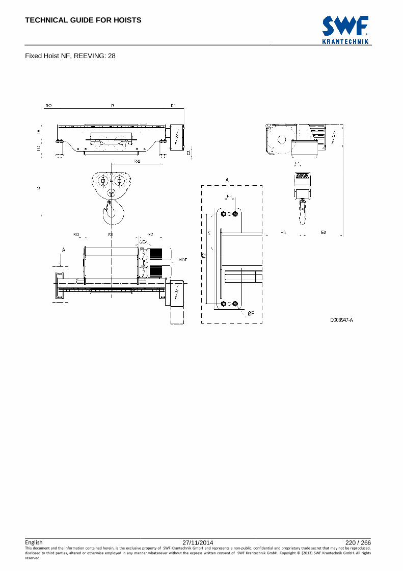
TECHNICAL GUIDE FOR HOISTS
English 27/11/2014 220 / 266This document and the information contained herein, is the exclusive property of SWF Krantechnik GmbH and represents a non-public, confidential and proprietary trade secret that may not be reproduced,
disclosed to third parties, altered or otherwise employed in any manner whatsoever without the express written consent of SWF Krantechnik GmbH. Copyright © (2013) SWF Krantechnik GmbH. All rights
reserved.
Fixed Hoist NF, REEVING: 28
TECHNICAL GUIDE FOR HOISTS
English 27/11/2014 221 / 266This document and the information contained herein, is the exclusive property of SWF Krantechnik GmbH and represents a non-public, confidential and proprietary trade secret that may not be reproduced,
disclosed to third parties, altered or otherwise employed in any manner whatsoever without the express written consent of SWF Krantechnik GmbH. Copyright © (2013) SWF Krantechnik GmbH. All rights
reserved.
MACHINERY HOIST

TECHNICAL GUIDE FOR HOISTS
English 27/11/2014 222 / 266This document and the information contained herein, is the exclusive property of SWF Krantechnik GmbH and represents a non-public, confidential and proprietary trade secret that may not be reproduced,
disclosed to third parties, altered or otherwise employed in any manner whatsoever without the express written consent of SWF Krantechnik GmbH. Copyright © (2013) SWF Krantechnik GmbH. All rights
reserved.

TECHNICAL GUIDE FOR HOISTS
English 27/11/2014 223 / 266This document and the information contained herein, is the exclusive property of SWF Krantechnik GmbH and represents a non-public, confidential and proprietary trade secret that may not be reproduced,
disclosed to third parties, altered or otherwise employed in any manner whatsoever without the express written consent of SWF Krantechnik GmbH. Copyright © (2013) SWF Krantechnik GmbH. All rights
reserved.
103 MACHINERY HOIST NBM1V, REEVING: M1
Hoist dimensions HOL Length M1 H2 T1 Weight
m code mm mm mm kg
24 A 318 182 270 95
38 C 448 288 400 105
Motor dimensions
Motor P1 P2 P3 A3 S3 MOT (mm) 382 442 472 442 522
Weight (kg) 21 31 35 32 28
Trolley dimensions
∅∅∅∅F E1 GEA H1 M2 T2 TH TO
14 291 114 28 24 300 386 40
D002083_A 062495
Note: All dimensions in mm. Note: Weight calculated with P1 motor. Note: Motor P1 is unavailable for load classes 600 and 800 kg. Note: Max rope angle from drum groove +/- 4 degrees.

TECHNICAL GUIDE FOR HOISTS
English 27/11/2014 224 / 266This document and the information contained herein, is the exclusive property of SWF Krantechnik GmbH and represents a non-public, confidential and proprietary trade secret that may not be reproduced,
disclosed to third parties, altered or otherwise employed in any manner whatsoever without the express written consent of SWF Krantechnik GmbH. Copyright © (2013) SWF Krantechnik GmbH. All rights
reserved.
Machinery Hoist NBM1V, REEVING: M1
Note: Rope directions presented in detail views: A: down, B: left, C: up, D: right.

TECHNICAL GUIDE FOR HOISTS
English 27/11/2014 225 / 266This document and the information contained herein, is the exclusive property of SWF Krantechnik GmbH and represents a non-public, confidential and proprietary trade secret that may not be reproduced,
disclosed to third parties, altered or otherwise employed in any manner whatsoever without the express written consent of SWF Krantechnik GmbH. Copyright © (2013) SWF Krantechnik GmbH. All rights
reserved.
104 MACHINERY HOIST NBM2V, REEVING: M2, ROPES TO SA ME DIRECTION
Hoist dimensions
HOL Length M1 H2 T1 Weight m code mm mm mm kg
7 A 318 53 270 95
15 C 448 118 400 105
Motor dimensions
Motor P1 P2 P3 A3 S3 MOT (mm) 382 442 472 442 522
Weight (kg) 21 31 35 32 28
Trolley dimensions
∅∅∅∅F E1 GEA H1 H3 M2 T2 TH TO
14 291 114 28 74 24 300 386 40 D002085_A
062496 Note: All dimensions in mm. Note: Weight calculated with P1 motor. Note: Motor P1 is unavailable for load classes 600 and 800 kg. Note: Rope 1 closer to the gearbox. Note: max rope angle from drum groove +/- 4 degrees.

TECHNICAL GUIDE FOR HOISTS
English 27/11/2014 226 / 266This document and the information contained herein, is the exclusive property of SWF Krantechnik GmbH and represents a non-public, confidential and proprietary trade secret that may not be reproduced,
disclosed to third parties, altered or otherwise employed in any manner whatsoever without the express written consent of SWF Krantechnik GmbH. Copyright © (2013) SWF Krantechnik GmbH. All rights
reserved.
Machinery Hoist NBM2V, REEVING: , Ropes To Same Direction
Note: Rope directions presented in detail view: A: down, B: left, C: up, D: right.

TECHNICAL GUIDE FOR HOISTS
English 27/11/2014 227 / 266This document and the information contained herein, is the exclusive property of SWF Krantechnik GmbH and represents a non-public, confidential and proprietary trade secret that may not be reproduced,
disclosed to third parties, altered or otherwise employed in any manner whatsoever without the express written consent of SWF Krantechnik GmbH. Copyright © (2013) SWF Krantechnik GmbH. All rights
reserved.
105 MACHINERY HOIST NBM2V, REEVING: M2, ROPES TO OP POSITE DIRECTIONS
Hoist dimensions
HOL Length M1 H2 T1 Weight m code mm mm mm kg
7 A 318 53 270 95
15 C 448 118 400 105
Motor dimensions
Motor P1 P2 P3 A3 S3 MOT (mm) 382 442 472 442 522
Weight (kg) 21 31 35 32 28
Trolley dimensions
∅∅∅∅F E1 E2 GEA H1 H3 M2 T2 TH TO
14 291 307 114 28 74 24 300 386 40 D002084_A
062561 Note: All dimensions in mm. Note: Weight calculated with P1 motor. Note: Motor P1 is unavailable for load classes 600 and 800 kg. Note: Both ropes within the allowed rope angle! Note: Max rope angle from drum groove +/- 4 degrees.

TECHNICAL GUIDE FOR HOISTS
English 27/11/2014 228 / 266This document and the information contained herein, is the exclusive property of SWF Krantechnik GmbH and represents a non-public, confidential and proprietary trade secret that may not be reproduced,
disclosed to third parties, altered or otherwise employed in any manner whatsoever without the express written consent of SWF Krantechnik GmbH. Copyright © (2013) SWF Krantechnik GmbH. All rights
reserved.
Machinery Hoist NBM2V, REEVING: M2, Ropes To Opposite Directions
Note: Rope directions presented in detail views: A: rope 1 down, B: rope 1 left, C: rope 2 up, D: rope 2 right. Note: Detail view E shows the optional and transport position of the cubicle.

TECHNICAL GUIDE FOR HOISTS
English 27/11/2014 229 / 266This document and the information contained herein, is the exclusive property of SWF Krantechnik GmbH and represents a non-public, confidential and proprietary trade secret that may not be reproduced,
disclosed to third parties, altered or otherwise employed in any manner whatsoever without the express written consent of SWF Krantechnik GmbH. Copyright © (2013) SWF Krantechnik GmbH. All rights
reserved.
106 MACHINERY HOIST NCM1V, REEVING: M1
Hoist dimensions HOL Length M1 H2 T1 Weight
m code mm mm mm kg
24 B 350 196 300 140
36 C 450 292 400 150
48 D 550 392 500 160
62 E 670 506 620 170
Motor dimensions
Motor P3 P4 A3 S3 S5 MOT (mm) 470 571 440 520 599
Weight (kg) 35 53 32 28 53
Trolley dimensions
∅∅∅∅F E1 GEA H1 M2 T2 TH TO
18 294 119 40 25 350 456 43 D002108_A
062500 Note: All dimensions in mm. Note: Weight calculated with P3 motor. Note: Motor S5 is unavailable for load class 1600 kg. Note: Max rope angle from drum groove +/- 4 degrees.
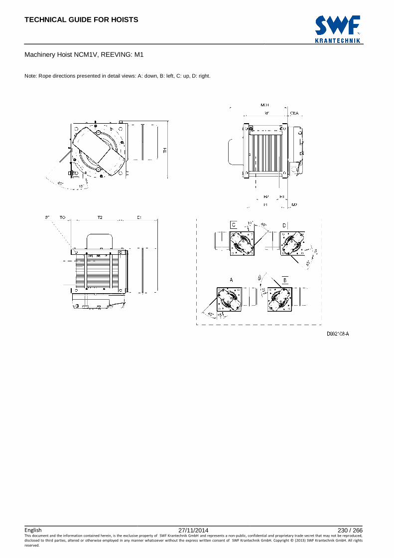
TECHNICAL GUIDE FOR HOISTS
English 27/11/2014 230 / 266This document and the information contained herein, is the exclusive property of SWF Krantechnik GmbH and represents a non-public, confidential and proprietary trade secret that may not be reproduced,
disclosed to third parties, altered or otherwise employed in any manner whatsoever without the express written consent of SWF Krantechnik GmbH. Copyright © (2013) SWF Krantechnik GmbH. All rights
reserved.
Machinery Hoist NCM1V, REEVING: M1
Note: Rope directions presented in detail views: A: down, B: left, C: up, D: right.

TECHNICAL GUIDE FOR HOISTS
English 27/11/2014 231 / 266This document and the information contained herein, is the exclusive property of SWF Krantechnik GmbH and represents a non-public, confidential and proprietary trade secret that may not be reproduced,
disclosed to third parties, altered or otherwise employed in any manner whatsoever without the express written consent of SWF Krantechnik GmbH. Copyright © (2013) SWF Krantechnik GmbH. All rights
reserved.
107 MACHINERY HOIST NCM2V, REEVING: M2, ROPES TO SA ME DIRECTION
Hoist dimensions
HOL Length M1 H2 T1 Weight m code mm mm mm kg
9.5 B 350 62 300 140
17 C 450 112 400 150
25 D 550 162 500 160
34 E 670 222 620 170
Motor dimensions
Motor P3 P4 A3 S3 S5 MOT (mm) 470 571 440 520 599
Weight (kg) 35 53 32 28 53
Trolley dimensions
∅∅∅∅F E1 GEA H1 H3 M2 T2 TH TO
18 294 119 40 80 25 350 456 43 D002110_A
062505 Note: All dimensions in mm. Note: Weight calculated with P3 motor. Note: Motor S5 is unavailable for load class 1600 kg. Note: Max rope angle from drum groove +/- 4 degrees.

TECHNICAL GUIDE FOR HOISTS
English 27/11/2014 232 / 266This document and the information contained herein, is the exclusive property of SWF Krantechnik GmbH and represents a non-public, confidential and proprietary trade secret that may not be reproduced,
disclosed to third parties, altered or otherwise employed in any manner whatsoever without the express written consent of SWF Krantechnik GmbH. Copyright © (2013) SWF Krantechnik GmbH. All rights
reserved.
Machinery Hoist NCM2V, REEVING: M2, Ropes To Same Direction
Note: Rope directions presented in detail view: A: down, B: left, C: up, D: right.

TECHNICAL GUIDE FOR HOISTS
English 27/11/2014 233 / 266This document and the information contained herein, is the exclusive property of SWF Krantechnik GmbH and represents a non-public, confidential and proprietary trade secret that may not be reproduced,
disclosed to third parties, altered or otherwise employed in any manner whatsoever without the express written consent of SWF Krantechnik GmbH. Copyright © (2013) SWF Krantechnik GmbH. All rights
reserved.
108 MACHINERY HOIST NCM2V, REEVING: M2, ROPES TO OPPOSITE DIRECTIONS
Hoist dimensions
HOL Length M1 H2 T1 Weight m code mm mm mm kg
9.5 B 350 62 300 140
17 C 450 112 400 150
25 D 550 162 500 160
34 E 670 222 620 170
Motor dimensions
Motor P3 P4 A3 S3 S5 MOT (mm) 470 571 440 520 599
Weight (kg) 35 53 32 28 53
Trolley dimensions
∅∅∅∅F E1 E2 GEA H1 H3 M2 T2 TH TO
18 296 308 119 40 80 25 350 456 43 D002109_A
062501 Note: All dimensions in mm. Note: Weight calculated with P3 motor. Note: Motor S5 is unavailable for load class 1600 kg. Note: Max rope angle from drum groove +/- 4 degrees. Note: Rope 1 closer to the gearbox.

TECHNICAL GUIDE FOR HOISTS
English 27/11/2014 234 / 266This document and the information contained herein, is the exclusive property of SWF Krantechnik GmbH and represents a non-public, confidential and proprietary trade secret that may not be reproduced,
disclosed to third parties, altered or otherwise employed in any manner whatsoever without the express written consent of SWF Krantechnik GmbH. Copyright © (2013) SWF Krantechnik GmbH. All rights
reserved.
Machinery Hoist NCM2V, REEVING: M2, Ropes To Opposite Directions
Note: Rope directions presented in detail view: A: rope 1 down, B: rope 1 left, C: rope 2 up, D: rope 2 right. Note: Detail view E shows the optional and transport position of the cubicle.

TECHNICAL GUIDE FOR HOISTS
English 27/11/2014 235 / 266This document and the information contained herein, is the exclusive property of SWF Krantechnik GmbH and represents a non-public, confidential and proprietary trade secret that may not be reproduced,
disclosed to third parties, altered or otherwise employed in any manner whatsoever without the express written consent of SWF Krantechnik GmbH. Copyright © (2013) SWF Krantechnik GmbH. All rights
reserved.
109 MACHINERY HOIST NDM1V, REEVING: M1
Hoist dimensions HOL Length M1 H2 T1 Weight
m code mm mm mm kg
36 D 552 352 490 315
48 E 672 472 610 330
64 F 822 622 760 350
82 G 1012 812 950 370
Motor dimensions
Motor P5 P6 P7 A5 S5 S7 MOT (mm) 575 575 615 495 603 754
Weight (kg) 58 85 105 45 53 81
Trolley dimensions
∅∅∅∅F E1 GEA H1 M2 T2 TH TO
22 391 146 54 31 400 541 58 D002138_A
062940 Note: All dimensions in mm. Note: Weight calculated with P5 motor. Note: Motor S7 is unavailable for load class 3150 kg. Note: Max rope angle from drum groove +/- 4 degrees.

TECHNICAL GUIDE FOR HOISTS
English 27/11/2014 236 / 266This document and the information contained herein, is the exclusive property of SWF Krantechnik GmbH and represents a non-public, confidential and proprietary trade secret that may not be reproduced,
disclosed to third parties, altered or otherwise employed in any manner whatsoever without the express written consent of SWF Krantechnik GmbH. Copyright © (2013) SWF Krantechnik GmbH. All rights
reserved.
Machinery Hoist NDM1V, REEVING: M1
Note: Rope directions presented in detail view: A: down, B: left, C: up, D: right.

TECHNICAL GUIDE FOR HOISTS
English 27/11/2014 237 / 266This document and the information contained herein, is the exclusive property of SWF Krantechnik GmbH and represents a non-public, confidential and proprietary trade secret that may not be reproduced,
disclosed to third parties, altered or otherwise employed in any manner whatsoever without the express written consent of SWF Krantechnik GmbH. Copyright © (2013) SWF Krantechnik GmbH. All rights
reserved.
110 MACHINERY HOIST NDM2V, REEVING: M2, ROPES TO SA ME DIRECTION
Hoist dimensions
HOL Length M1 H2 T1 Weight m code mm mm mm kg
18 D 552 128 490 315
27 E 672 188 610 330
38 F 822 263 760 350
50 G 1012 358 950 370
Motor dimensions
Motor P5 P6 P7 A5 S5 S7 MOT (mm) 575 575 615 495 603 754
Weight (kg) 58 85 105 45 53 81
Trolley dimensions
∅∅∅∅F E1 E2 GEA H1 H3 M2 T2 TH TO
22 391 499 146 65 99 31 400 541 58 D002137_A
062942 Note: All dimensions in mm. Note: Weight calculated with P5 motor. Note: Motor S7 is unavailable for load class 3150 kg. Note: Max rope angle from drum groove +/- 4 degrees.

TECHNICAL GUIDE FOR HOISTS
English 27/11/2014 238 / 266This document and the information contained herein, is the exclusive property of SWF Krantechnik GmbH and represents a non-public, confidential and proprietary trade secret that may not be reproduced,
disclosed to third parties, altered or otherwise employed in any manner whatsoever without the express written consent of SWF Krantechnik GmbH. Copyright © (2013) SWF Krantechnik GmbH. All rights
reserved.
Machinery Hoist NDM2V, REEVING: M2, Ropes To Same Direction
Note: Rope directions presented in detail view: A: down, B: left, C: up, D: right.

TECHNICAL GUIDE FOR HOISTS
English 27/11/2014 239 / 266This document and the information contained herein, is the exclusive property of SWF Krantechnik GmbH and represents a non-public, confidential and proprietary trade secret that may not be reproduced,
disclosed to third parties, altered or otherwise employed in any manner whatsoever without the express written consent of SWF Krantechnik GmbH. Copyright © (2013) SWF Krantechnik GmbH. All rights
reserved.
111 MACHINERY HOIST NDM2V, REEVING: M2, ROPES TO OPPOSITE DIRECTIONS
Hoist dimensions
HOL Length M1 H2 T1 Weight m code mm mm mm kg
18 D 552 128 490 315
27 E 672 188 610 330
38 F 822 263 760 350
50 G 1012 358 950 370
Motor dimensions
Motor P5 P6 P7 A5 S5 S7 MOT (mm) 575 575 615 495 603 754
Weight (kg) 58 85 105 45 53 81
Trolley dimensions
∅∅∅∅F E1 E2 GEA H1 H3 M2 T2 TH TO
22 391 499 146 65 99 31 400 541 58 D002139_A
062943 Note: All dimensions in mm. Note: Weight calculated with P5 motor. Note: Motor S7 is unavailable for load class 3150 kg. Note: Rope 1 closer to the gearbox. Note: Max rope angle from drum groove +/- 4 degrees.
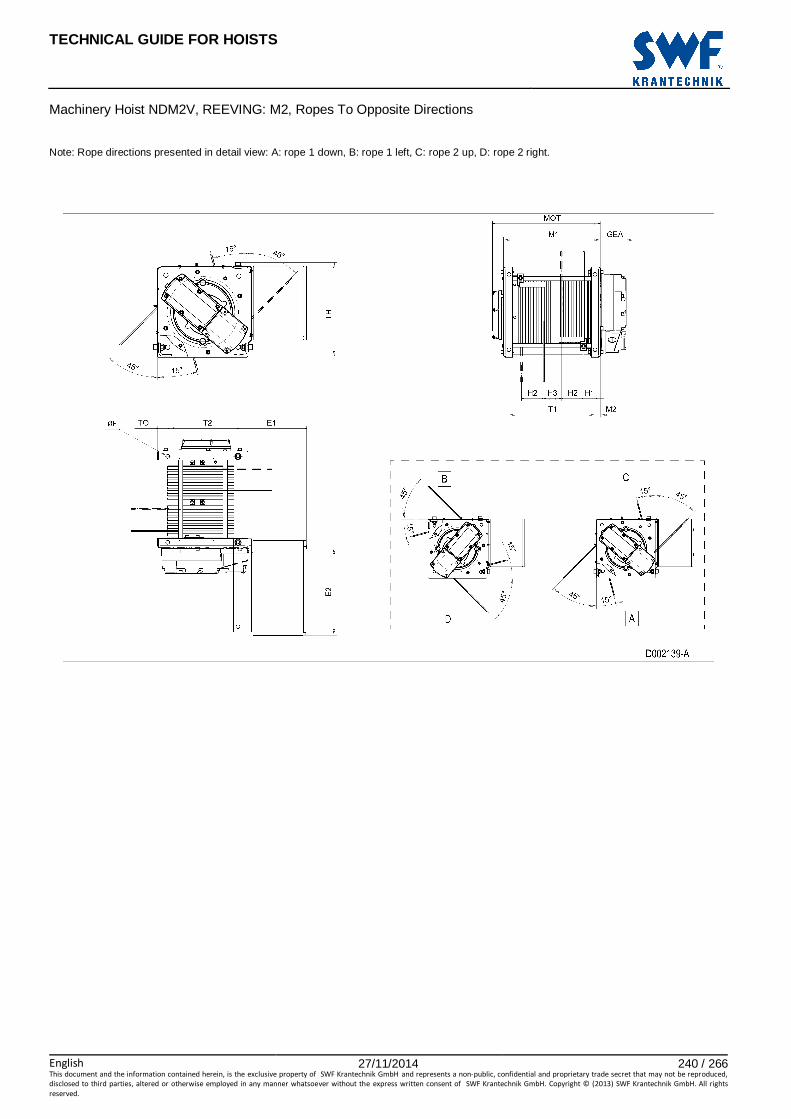
TECHNICAL GUIDE FOR HOISTS
English 27/11/2014 240 / 266This document and the information contained herein, is the exclusive property of SWF Krantechnik GmbH and represents a non-public, confidential and proprietary trade secret that may not be reproduced,
disclosed to third parties, altered or otherwise employed in any manner whatsoever without the express written consent of SWF Krantechnik GmbH. Copyright © (2013) SWF Krantechnik GmbH. All rights
reserved.
Machinery Hoist NDM2V, REEVING: M2, Ropes To Opposite Directions
Note: Rope directions presented in detail view: A: rope 1 down, B: rope 1 left, C: rope 2 up, D: rope 2 right.

TECHNICAL GUIDE FOR HOISTS
English 27/11/2014 241 / 266This document and the information contained herein, is the exclusive property of SWF Krantechnik GmbH and represents a non-public, confidential and proprietary trade secret that may not be reproduced,
disclosed to third parties, altered or otherwise employed in any manner whatsoever without the express written consent of SWF Krantechnik GmbH. Copyright © (2013) SWF Krantechnik GmbH. All rights
reserved.
112 MACHINERY HOIST NEM1V, REEVING: M1
Hoist dimensions HOL HOL* Length H2 T1 M1 Weight**
m m code mm mm mm kg
32 22 C 286 400 466 600
43 33 D 385 500 566 630
56.5 46.5 E 506 620 686 660
73 63 F 654 770 836 700
94.5 84.5 G 846 960 1026 740
122.5 112.5 H 1097 1210 1276 810
161.5 151.5 J 1446 1560 1626 900
195 185 K 1746 1860 1926 980
*HOL with drum brake **Presence of a drum brake will increase weight by 80 kgs.
Motor dimensions Motor P6 P7 P8 A7 S7 S8 SA
MOT (mm) 536 576 711 536 715 763 803
Weight (kg) 85 105 106 71 81 97 120
Trolley dimensions
∅∅∅∅F E1 E2 GEA H1 LIF M2 M3 T2 T3 T4 TH
21 300 669 218 57 62 33 44 660 540 420 809
TO 72
D002433_A 063844
Note: All dimensions in mm. Note: Weight calculated with P6 motor. Note: Max rope angle from drum groove +/- 4 degrees.

TECHNICAL GUIDE FOR HOISTS
English 27/11/2014 242 / 266This document and the information contained herein, is the exclusive property of SWF Krantechnik GmbH and represents a non-public, confidential and proprietary trade secret that may not be reproduced,
disclosed to third parties, altered or otherwise employed in any manner whatsoever without the express written consent of SWF Krantechnik GmbH. Copyright © (2013) SWF Krantechnik GmbH. All rights
reserved.
Machinery Hoist NEM1V, REEVING: M1 Note: Rope directions presented in detail views: A: down, B: left, C: up, D: right. Note: Detail view E for alternative mounting.

TECHNICAL GUIDE FOR HOISTS
English 27/11/2014 243 / 266This document and the information contained herein, is the exclusive property of SWF Krantechnik GmbH and represents a non-public, confidential and proprietary trade secret that may not be reproduced,
disclosed to third parties, altered or otherwise employed in any manner whatsoever without the express written consent of SWF Krantechnik GmbH. Copyright © (2013) SWF Krantechnik GmbH. All rights
reserved.
113 MACHINERY HOIST NEM2V, REEVING: M2
Hoist dimensions HOL HOL* Length H2 T1 M1 Weight**
m m code mm mm mm kg
37 23 E 242 620 686 660
48.5 34.5 F 317 770 836 700
63 49 G 412 960 1026 740
82 68 H 537 1210 1276 810
108.5 94.5 J 710 1560 1626 900
131.5 117.5 K 861 1860 1926 980
158.5 144.5 L 1037 2210 2276 1070
177.5 163.5 M 1162 2460 2526 1140
200.5 186.5 N 1312 2760 2826 1220
*HOL with drum brake **Presence of a drum brake will increase weight by 80 kgs.
Motor dimensions
Motor P6 P7 P8 A7 S7 S8 SA MOT (mm) 536 576 711 536 715 763 803
Weight (kg) 85 105 106 71 81 97 120
Trolley dimensions
∅∅∅∅F E1 E2 GEA H1 H3 LIF M2 M3 T2 T3 T4
21 308 669 218 53 30 62 33 44 660 540 420
TH TO 809 72
D002411_A 063845
Note: All dimensions in mm. Note: Weight calculated with P6 motor. Note: Angle of rope 2 can variate 0-360 degrees. Note: Max rope angle from drum groove +/- 4 degrees.

TECHNICAL GUIDE FOR HOISTS
English 27/11/2014 244 / 266This document and the information contained herein, is the exclusive property of SWF Krantechnik GmbH and represents a non-public, confidential and proprietary trade secret that may not be reproduced,
disclosed to third parties, altered or otherwise employed in any manner whatsoever without the express written consent of SWF Krantechnik GmbH. Copyright © (2013) SWF Krantechnik GmbH. All rights
reserved.
Machinery Hoist NEM2V, REEVING: M2 Note: Rope directions presented in detail views: A: down, B: left, C: up, D: right. Note: Detail view E for alternative mounting and rope 1 angle.
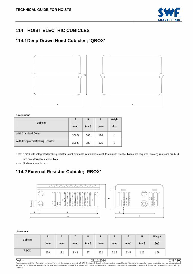
TECHNICAL GUIDE FOR HOISTS
English 27/11/2014 245 / 266This document and the information contained herein, is the exclusive property of SWF Krantechnik GmbH and represents a non-public, confidential and proprietary trade secret that may not be reproduced,
disclosed to third parties, altered or otherwise employed in any manner whatsoever without the express written consent of SWF Krantechnik GmbH. Copyright © (2013) SWF Krantechnik GmbH. All rights
reserved.
114 HOIST ELECTRIC CUBICLES
114.1 Deep-Drawn Hoist Cubicles; ‘QBOX’
Dimensions
Cubicle
A
(mm)
B
(mm)
C
(mm)
Weight
(kg)
With Standard Cover 306.5 383 124 4
With Integrated Braking Resistor 306.5 383 125 8
Note: QBOX with integrated braking resistor is not available in stainless steel. If stainless steel cubicles are required, braking resistors are built
into an external resistor cubicle.
Note: All dimensions in mm.
114.2 External Resistor Cubicle; ‘RBOX’
Dimensions
Cubicle
A
(mm)
B
(mm)
C
(mm)
D
(mm)
E
(mm)
F
(mm)
G
(mm)
H
(mm)
Weight
(kg)
‘RBOX’ 279 192 93.8 37 232 72.8 33.5 125 1.68
TECHNICAL GUIDE FOR HOISTS
English 27/11/2014 246 / 266This document and the information contained herein, is the exclusive property of SWF Krantechnik GmbH and represents a non-public, confidential and proprietary trade secret that may not be reproduced,
disclosed to third parties, altered or otherwise employed in any manner whatsoever without the express written consent of SWF Krantechnik GmbH. Copyright © (2013) SWF Krantechnik GmbH. All rights
reserved.
Note: All dimensions in mm.

TECHNICAL GUIDE FOR HOISTS
English 27/11/2014 247 / 266This document and the information contained herein, is the exclusive property of SWF Krantechnik GmbH and represents a non-public, confidential and proprietary trade secret that may not be reproduced,
disclosed to third parties, altered or otherwise employed in any manner whatsoever without the express written consent of SWF Krantechnik GmbH. Copyright © (2013) SWF Krantechnik GmbH. All rights
reserved.
114.3 Hinged Hoist Cubicles
Dimensions
Cubicle
A
(mm)
B
(mm)
C
(mm)
D
(mm)
E
(mm)
F
(mm)
G
(mm)
H
(mm)
Weight
(kg)
H260x250x160 260 160 250 25 210 140 25 200 4.5
H350x300x200 350 213 300 18 310 192 40.5 230 9.5
H400x400x250 400 255 400 50 300 235 50 300 13
H540x420x300 540 305 420 75 390 285 27.5 365 18
H540x650x300 540 308 650 75 390 285 27.5 595 28
H600x250x200 600 216 250 50 500 195 50 150 14
H600x600x300 600 308 600 50 500 285 50 500 32
H900x250x200 900 216 250 50 800 195 50 150 17
H900x400x250 900 257 397 50 800 234 48.5 300 24
H1000x600x300 1000 305 600 50 900 284 50 500 49

TECHNICAL GUIDE FOR HOISTS
English 27/11/2014 248 / 266This document and the information contained herein, is the exclusive property of SWF Krantechnik GmbH and represents a non-public, confidential and proprietary trade secret that may not be reproduced,
disclosed to third parties, altered or otherwise employed in any manner whatsoever without the express written consent of SWF Krantechnik GmbH. Copyright © (2013) SWF Krantechnik GmbH. All rights
reserved.
H1200x400x250 1200 257 397 50 1100 234 48.5 300 31
Note: All dimensions in mm.

TECHNICAL GUIDE FOR HOISTS
English 27/11/2014 249 / 266This document and the information contained herein, is the exclusive property of SWF Krantechnik GmbH and represents a non-public, confidential and proprietary trade secret that may not be reproduced,
disclosed to third parties, altered or otherwise employed in any manner whatsoever without the express written consent of SWF Krantechnik GmbH. Copyright © (2013) SWF Krantechnik GmbH. All rights
reserved.
114.4 Hoist Electric Cubicle Selection With Crane E lectric Provisions
Hoist
Type
Main
Cubicle
Auxiliary
Cubicle
Optional Main
Cubicles
Low Headroom
QA-L Q-Box Q-Box -
QB-L Q-Box Q-Box -
QC-L 540x420x300 - 540x650x300
Normal Headroom
QA-N Q-Box Q-Box -
QB-N Q-Box Q-Box -
QC-N 540x420x300 - 540x650x300
QD-N, 400V or 460V
Basic electrics 600x600x300 - 1000x600x300
Standard electrics
D2M 002 600x600x300 - 1000x600x300
D2M 003-004 1000x600x300 - -
D2M 005-007 600x600x300* - 1000x600x300
Special electrics
D2C 002-005 600x600x300 600x400x250 1000x600x300
D2C 007-011 600x600x300* - 1000x600x300
QD-N, other voltages
Basic electrics 1000x600x300 - -
Standard electrics
D2M 002 1000x600x300 - -
D2M 003-004 1000x600x300 600x400x250 -
D2M 005-007 600x600x300* - 1000x600x300
Special electrics
D2C 002-011 600x600x300* - 1000x600x300

TECHNICAL GUIDE FOR HOISTS
English 27/11/2014 250 / 266This document and the information contained herein, is the exclusive property of SWF Krantechnik GmbH and represents a non-public, confidential and proprietary trade secret that may not be reproduced,
disclosed to third parties, altered or otherwise employed in any manner whatsoever without the express written consent of SWF Krantechnik GmbH. Copyright © (2013) SWF Krantechnik GmbH. All rights
reserved.
Double Girder
QA-M/H 600x250x200 - 900x250x200
QB-M/H 600x250x200 - 900x250x200
QC-M/H 900x400x250 - 1200x400x250
QC-W 900x250x200 - 600x250x200
QD-M 1000x600x300 - 900x400x250
600x600x300
QE-M 1000x600x300 - 600x600x300
Fixed Hoist
QA-F Q-Box - -
QB-F Q-Box - -
QC-F 540x420x300 - 540x650x300
QD-F 600x600x300 - 1000x600x300
QE-F 600x600x300 - 1000x600x300
Machinery Hoist
QA-V Q-Box - -
QB-V Q-Box - -
QC-V 540x420x300 - 540x650x300
QD-V 600x600x300 - 1000x600x300
*) Inverter in bridge panel

TECHNICAL GUIDE FOR HOISTS
English 27/11/2014 251 / 266This document and the information contained herein, is the exclusive property of SWF Krantechnik GmbH and represents a non-public, confidential and proprietary trade secret that may not be reproduced,
disclosed to third parties, altered or otherwise employed in any manner whatsoever without the express written consent of SWF Krantechnik GmbH. Copyright © (2013) SWF Krantechnik GmbH. All rights
reserved.
114.5 Hoist Electric Cubicle Selection With Solo El ectric Provisions
Hoist
Type
Main
Cubicle
Auxiliary
Cubicle
Optional Main
Cubicles
Solo Electrics in
External Cubicle
Low Headroom
QA-L Q-Box Q-Box - YES
QB-L Q-Box Q-Box - YES
QC-L 540x420x300 - 540x650x300 YES
Normal Headroom
QA-N Q-Box Q-Box 400x400x250 YES
QB-N Q-Box Q-Box 400x400x250 YES
QC-N 540x420x300 - 540x650x300 YES
QD-N, 400V or 460V
Basic electrics 1000x600x300 - - NO
Standard electrics
D2M 002 1000x600x300 - - NO
D2M 003-004 1000x600x300 - - NO
D2M 005-007 1000x600x300 1000x600x300 - NO
Special electrics
D2C 002-005 1000x600x300 600x400x250 - NO
D2C 007-011 1000x600x300 1000x600x300 - NO
QD-N, other voltages
Basic electrics 1000x600x300 - - NO
Standard electrics
D2M 002 1000x600x300 - - NO
D2M 003-004 1000x600x300 600x400x250 - NO
D2M 005-007 1000x600x300 1000x600x300** NO
Special electrics
D2C 002-005 1000x600x300 600x400x250 - NO

TECHNICAL GUIDE FOR HOISTS
English 27/11/2014 252 / 266This document and the information contained herein, is the exclusive property of SWF Krantechnik GmbH and represents a non-public, confidential and proprietary trade secret that may not be reproduced,
disclosed to third parties, altered or otherwise employed in any manner whatsoever without the express written consent of SWF Krantechnik GmbH. Copyright © (2013) SWF Krantechnik GmbH. All rights
reserved.
D2C 007-011 1000x600x300 1000x600x300** - NO
**) Transformer in bridge panel
191937

TECHNICAL GUIDE FOR HOISTS
English 27/11/2014 253 / 266This document and the information contained herein, is the exclusive property of SWF Krantechnik GmbH and represents a non-public, confidential and proprietary trade secret that may not be reproduced,
disclosed to third parties, altered or otherwise employed in any manner whatsoever without the express written consent of SWF Krantechnik GmbH. Copyright © (2013) SWF Krantechnik GmbH. All rights
reserved.
115 SOLO ELECTRICS IN EXTERNAL CUBICLE, NB/NC/ND LO W HEADROOM AND NORMAL HEADROOM HOISTS
Solo electrics in external cubicle increase the hoist overall dimensions. Variable dimension indicates the dimension that is extended by the reported value to produce the new hoist overall dimension ES due to the presence of solo electrics. See the appropriate variable dimensions from the data of the hoist in question. Hoists not reported here don’t have their overall dimensions affected by solo electrics.
NB/NC Hoists
Hoist Case ES mm
NB, Low Headroom A B/2 + 697
NC, Low Headroom A B/2 + 709
NB, Reeving: 02, Normal Headroom A 813
NB, Reeving: 04, Normal Headroom A 797
NC, Reeving: 02, Normal Headroom A 843
NC, Reeving: 04, Normal Headroom A 818
ND Hoists
Hoist Case ES mm
ND, Reeving: 02, Low Headroom B 442
ND, Reeving: 04, Low Headroom B 520
ND, Normal Headroom, Reeving: 02, Normal Track, Length Codes D/E B 548
ND, Normal Headroom, Reeving: 02, Normal Track, Length Codes F/G B 523
ND, Normal Headroom, Reeving: 04, Normal Track, Length Codes D/E B 628
ND, Normal Headroom, Reeving: 04, Normal Track, Length Codes F/G B 603
ND, Normal Headroom, Reeving: 02, Curved Track B 526
ND, Normal Headroom, Reeving: 04, Curved Track B 610
ND, Normal Headroom, Reeving: 06/08, Length Codes D/E/F B 684
ND, Normal Headroom, Reeving: 22/24, Length Codes D/E/F B 684
ND, Normal Headroom, Reeving: 26/28, Length Codes E/F B 719
ND hoist ES.dimensions given with maximum amount of counterweights. D007500_A
157545 Note: All dimensions in mm.

TECHNICAL GUIDE FOR HOISTS
English 27/11/2014 254 / 266This document and the information contained herein, is the exclusive property of SWF Krantechnik GmbH and represents a non-public, confidential and proprietary trade secret that may not be reproduced,
disclosed to third parties, altered or otherwise employed in any manner whatsoever without the express written consent of SWF Krantechnik GmbH. Copyright © (2013) SWF Krantechnik GmbH. All rights
reserved.
Solo Electrics In External Cubicle, NB/NC/ND Low Headroom And Normal Headroom Hoists

TECHNICAL GUIDE FOR HOISTS
English 27/11/2014 255 / 266This document and the information contained herein, is the exclusive property of SWF Krantechnik GmbH and represents a non-public, confidential and proprietary trade secret that may not be reproduced,
disclosed to third parties, altered or otherwise employed in any manner whatsoever without the express written consent of SWF Krantechnik GmbH. Copyright © (2013) SWF Krantechnik GmbH. All rights
reserved.
116 HOOK OPERATED ULTIMATE HOISTING LIMIT The hook operated ultimate hoisting limit is adjusted to engage when the hook is in the minimum C-dimension attainable with a given hoist, as shown in the dimension tables in this technical guide. The minimum C-dimension is limited by the surrounding steel structure and rope fleet angles. The primary hoisting limit switch must be set to engage before the ultimate limit engagement point. The actual C-dimension is thus increased by the difference between these engagement points. Additionally, in some trolley constructions, the steel structure of the ultimate limit may restrict hook travel, further impacting the C-dimension. This is the case especially with low headroom trolleys, where available space is most constricted. The tables below show the C-dimension increase for each hoist type.
Double Girder Hoists
Low Headroom Hoists
Hoist Reeving C Increase Hoist Reeving B min B max C Increase mm mm mm mm
NB 02 90
NB
all 80 270 135
04 140 271 320 105
NC all 90 321 370 75
ND
02/04 120 371 410 50
06/08 50
NC
02
100 250 215
22/24/26/28 50 251 300 185
NE/NF all 50 301 350 150
351 400 120
Fixed Hoists 401 450 85
Hoist Reeving C Increase 451 490 60
mm
04
100 199 80
NB all 205 200 249 110
NC all 90 250 300 145
ND
02/04 120 301 350 115
06/08 50 351 400 80
22/24/26/28 50 401 450 50
NE/NF all 50 451 490 20
A2
100 300 165
Normal Headroom Hoists 301 350 140
351 400 110
Hoist Reeving C Increase 401 450 75
mm 451 490 45
NB/NC all 120
A4
100 300 175
ND
02/04 120 301 350 140
06/08 50 351 400 110
22/24/26/28 50 401 450 75
ND/NE all 50 451 490 45
ND all 100 610 100
157665
Note: All dimensions in mm.
TECHNICAL GUIDE FOR HOISTS
English 27/11/2014 256 / 266This document and the information contained herein, is the exclusive property of SWF Krantechnik GmbH and represents a non-public, confidential and proprietary trade secret that may not be reproduced,
disclosed to third parties, altered or otherwise employed in any manner whatsoever without the express written consent of SWF Krantechnik GmbH. Copyright © (2013) SWF Krantechnik GmbH. All rights
reserved.

TECHNICAL GUIDE FOR HOISTS
English 27/11/2014 257 / 266This document and the information contained herein, is the exclusive property of SWF Krantechnik GmbH and represents a non-public, confidential and proprietary trade secret that may not be reproduced,
disclosed to third parties, altered or otherwise employed in any manner whatsoever without the express written consent of SWF Krantechnik GmbH. Copyright © (2013) SWF Krantechnik GmbH. All rights
reserved.
117 DOUBLE GIRDER TROLLEY OPTIONAL FEATURES Double girder trolley optional features are installed at the end of the hoist end carriages, thus increasing the hoist overall dimensions BU and RO. The following table shows how much the overall dimensions are increased for each end carriage type (discernable by the end carriage wheel diameter ∅WD). The figures are those of how much an individual option affects the total length at one end of the end carriage.
Dimension Increase To Dimensions BU and RO By An In dividual Option
∅∅∅∅WD Anti-Jump Catch Guide Roller Rail Sweep Proximity Sensor
BU RO BU RO BU RO BU RO* mm mm mm mm mm mm mm mm mm
90 10 347 N/A N/A 236 - - 174
110 10 332 200 50 236 - - 159
140 10 332 200 50 236 - - 159
200 10 308 200 33 236 - - 135
250 - 291 250 26 250 - - 100 With 3 Wheels - 247 250 - 250 - - 56
*Maximum effect, when longer fixing plate is used and installation is done as indicated on the picture with letter ‘A’. Available buffer extensions lengths according to wh eel diameter.
∅∅∅∅WD mm
Buffer Extension Length
100 200 250 300 400 500 600 700 750 1000 1500
mm mm mm mm mm mm mm mm mm mm mm
90 x x x x x x x
110 x x x x x x x
140 x x x x x x x
200 x x x x x x x
250 x x x x x x With 3 Wheels x x x x x x
Buffer extension length is added to dimension BU. Buffer extensions never increase hoist overall dimensions in direction of dimension RO.
D007501_A 157729
Note: All dimensions in mm. Note: Anti-Jump Catches are installed in pairs, one at each end of the end carriage. Note: Guide rollers are always installed on the electric cubicle side, and they are adjustable for rails 80–120 mm wide. The end carriages are then equipped with flangeless wheels. Guide rollers are not available for the smallest end carriage.

TECHNICAL GUIDE FOR HOISTS
English 27/11/2014 258 / 266This document and the information contained herein, is the exclusive property of SWF Krantechnik GmbH and represents a non-public, confidential and proprietary trade secret that may not be reproduced,
disclosed to third parties, altered or otherwise employed in any manner whatsoever without the express written consent of SWF Krantechnik GmbH. Copyright © (2013) SWF Krantechnik GmbH. All rights
reserved.
Double Girder Trolley Optional Features

TECHNICAL GUIDE FOR HOISTS
English 27/11/2014 259 / 266This document and the information contained herein, is the exclusive property of SWF Krantechnik GmbH and represents a non-public, confidential and proprietary trade secret that may not be reproduced,
disclosed to third parties, altered or otherwise employed in any manner whatsoever without the express written consent of SWF Krantechnik GmbH. Copyright © (2013) SWF Krantechnik GmbH. All rights
reserved.
118 SERVICE PLATFORM: DOUBLE GIRDER TROLLEY, MEDIUM
Service Platform Dimensions Buffer Extension Lengths* Hoist End
Carriage PL1 PL2 PL3 PH1 PH2 PW Travelling
Motor Side Hoisting Unit
Side mm mm mm mm mm mm mm mm
NC QNC09 2275 495 495 749 1168 244 500 500
ND QNC11 2475 545 555 748 1168 244 500 600
ND QNC14 2475 485 585 745 1168 244 500 600
ND QNC20 2475 485 585 693 1168 244 500 600
NE QNC14 2895 572 498 555 1168 244 600 500
NE QNC20 2895 554 480 493 1168 244 600 500
NE QNC25 2895 563 469 408 1168 244 750 500
NF QNC20 2895 554 480 493 1168 244 600 500
NF QNC25 2895 563 469 408 1168 244 750 500
NF QNC25B 2895 399 553 373 1168 244 750 500
*Use buffer extensions when two hoists on track. Service Platform Weights NC/ND
R SP1 SP2 SP3
mm
One platform, hoisting unit side
kg
Two platforms, one on each side
kg
One platform, travelling motor side, ND only.
kg
1400 244 356 244
1700 265 398 265
2000 291 448 291
2400 319 505 319
Service Platform Weights NE/NF*
R SP1 SP2 SP3
mm
One platform, hoisting unit side
kg
Two platforms, one on each side
kg
One platform, travelling motor side
kg
1400 243 358 249
1700 267 406 274
2000 290 455 299
2400 321 520 333
2700 345 568 358
3100 376 636 394
3400 399 683 418
3800 430 748 451
4200 462 812 485
* If the end carriage is QNC25B, reported weight increases by 20 kg. D007355_A
135661 Note: All dimensions in mm. Note: All service platforms are available for medium double girder trolleys ONLY.
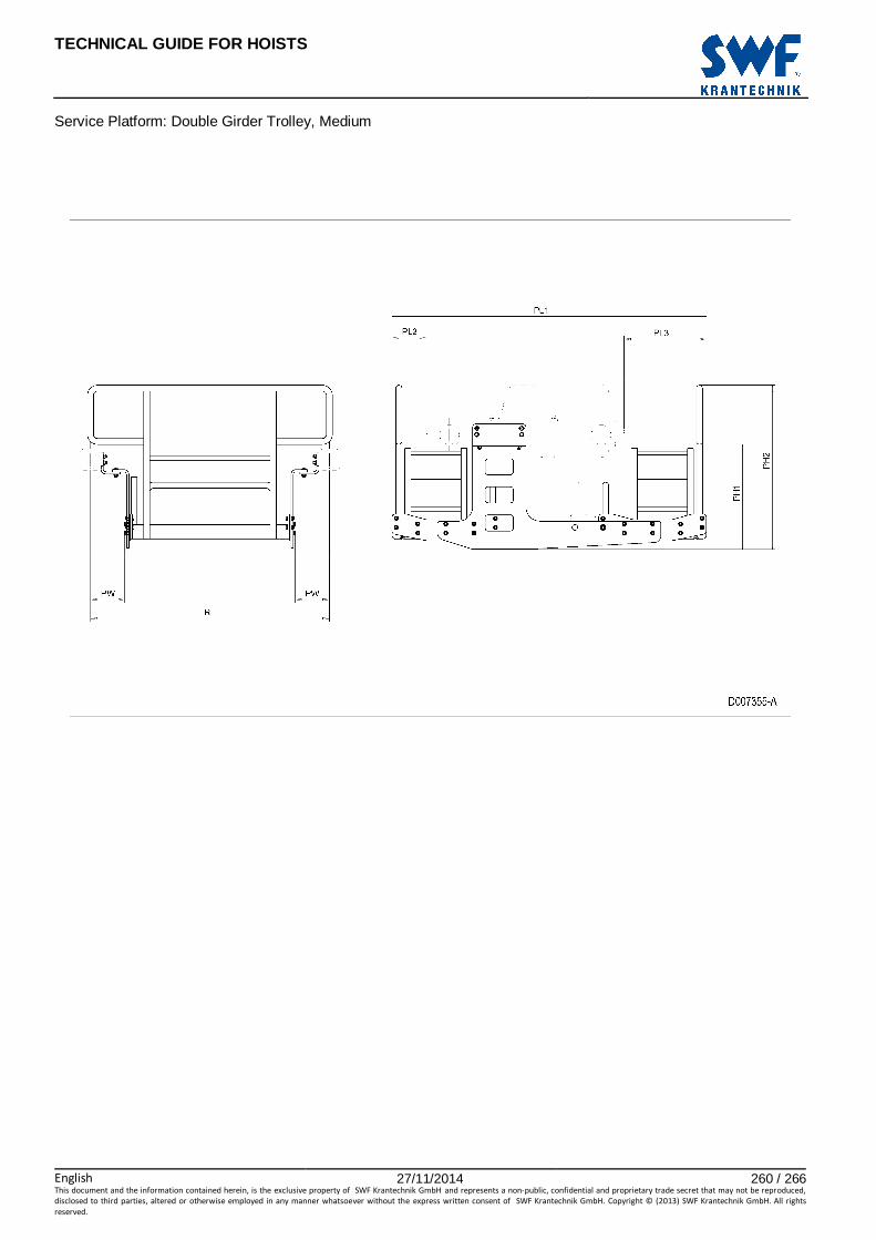
TECHNICAL GUIDE FOR HOISTS
English 27/11/2014 260 / 266This document and the information contained herein, is the exclusive property of SWF Krantechnik GmbH and represents a non-public, confidential and proprietary trade secret that may not be reproduced,
disclosed to third parties, altered or otherwise employed in any manner whatsoever without the express written consent of SWF Krantechnik GmbH. Copyright © (2013) SWF Krantechnik GmbH. All rights
reserved.
Service Platform: Double Girder Trolley, Medium

TECHNICAL GUIDE FOR HOISTS
English 27/11/2014 261 / 266This document and the information contained herein, is the exclusive property of SWF Krantechnik GmbH and represents a non-public, confidential and proprietary trade secret that may not be reproduced,
disclosed to third parties, altered or otherwise employed in any manner whatsoever without the express written consent of SWF Krantechnik GmbH. Copyright © (2013) SWF Krantechnik GmbH. All rights
reserved.
119 HOOK
119.1 Standard Hook Block Dimensions
Standard Hook Block Dimensions
Hoist Rope Hoist duty Hook Fig. Hook block dimensions (mm) Weight frame falls 1Am/M4 2m/M5 3m/M6 forging H H1 H2 H3 D B (kg)
Z 02 M5 RSN 1 V 1 385 84 261 72 168 108 9.3
Z 04 M5 RSN 1.6 V 2 391 84 258 77 168 202 16.2
B 02 M5 M6 RSN 1 V 1 385 84 261 72 168 108 9.3
B 04 M5 M6 HBC 1.6 V 2 337 84 198 54 168 221 13
C 02 M4 M5 M6 RSN 1 V 1 425 102 282 72 204 118 14
C 04 M5 M6 HBC 2.5 V 2 426 102 259 92 204 270 22
C 04 M4 HBC 2.5 V 2 443 102 276 81 204 241 31.5
C A2 M5 M6 RSN 1 V 1 385 84 261 72 168 108 9.3
C A4 M5 M6 HBC 1.6 V 2 337 84 198 54 168 221 13
D 02 M4 M5 M6 HBC 2.5 V 1 578 142 371 92 283 148 31
D 04 M5 M6 HBC 5 V 2 548 142 316 90 283 376 46.5
D 04 M4 HBC 5 V 2 604 142 372 111 283 341 77.5
D 06 M5 M6 HBC 5 V 4 740 155 495 101 310 243 86
D 08 M4 M5 HBC 5 V 4 740 155 495 101 310 243 91
D 22 M5 M6 HBC 2.5 V 3 541 115 361 66 230 203 37
D 24 M5 M6 RSN 6 V 3 639 120 433 102 530 243 100
D 26 M5 M6 RSN 6 V 3 639 120 433 102 530 243 104
D 28 M4 M5 RSN 6 V 3 639 120 433 102 530 243 110
E 02 M4 M5 M6 HBC 5 V 4 830 205 535 101 410 244 98
E 04 M4 M5 M6 HBC 5 V 4 830 205 535 101 410 244 111
E 06 M4 M5 M6 RSN 10 T 4 966 205 654 112 410 282 181
E 08 M4 M5 RSN 16 T 4 1119 205 780 160 410 294 251
E 22 M4 M5 M6 HBC 5 V 4 740 155 495 101 310 243 78
E 24 M4 M5 M6 RSN 6 V 3 719 160 473 102 700 275 143
E 26 M4 M5 M6 RSN 10 T 3 830 160 564 117 700 282 192
E 28 M4 M5 RSN 16 T 3 974 160 680 160 700 294 277
F 22 M4 M5 M6 RSN 6 V 4 844 205 553 102 410 244 111
F 24 M4 M5 M6 RSN 16 T 3 1034 200 700 160 910 377 373
F 26 M4 M5 M6 RFN 20 T 3 1118 200 766 185 910 377 478
F 28 M4 M5 RFN 25 T 3 1219 200 847 205 910 377 603
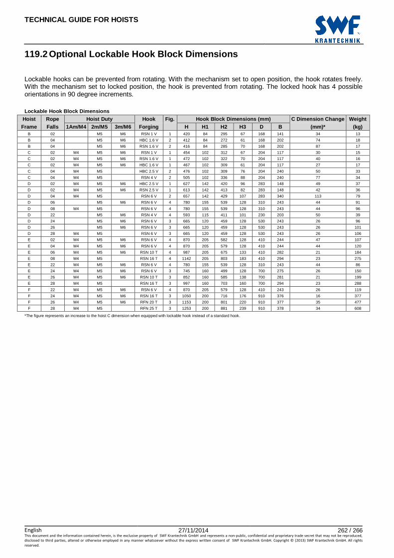
TECHNICAL GUIDE FOR HOISTS
English 27/11/2014 262 / 266This document and the information contained herein, is the exclusive property of SWF Krantechnik GmbH and represents a non-public, confidential and proprietary trade secret that may not be reproduced,
disclosed to third parties, altered or otherwise employed in any manner whatsoever without the express written consent of SWF Krantechnik GmbH. Copyright © (2013) SWF Krantechnik GmbH. All rights
reserved.
119.2 Optional Lockable Hook Block Dimensions
Lockable hooks can be prevented from rotating. With the mechanism set to open position, the hook rotates freely. With the mechanism set to locked position, the hook is prevented from rotating. The locked hook has 4 possible orientations in 90 degree increments. Lockable Hook Block Dimensions
Hoist Rope Hoist Duty Hook Fig. Hook Block Dimensions (mm) C Dimension Change Weight Frame Falls 1Am/M4 2m/M5 3m/M6 Forging H H1 H2 H3 D B (mm)* (kg)
B 02 M5 M6 RSN 1 V 1 420 84 295 67 168 141 34 13
B 04 M5 M6 HBC 1.6 V 2 412 84 272 61 168 202 74 18
B 04 M5 M6 RSN 1.6 V 2 416 84 285 70 168 202 87 17
C 02 M4 M5 M6 RSN 1 V 1 454 102 312 67 204 117 30 15
C 02 M4 M5 M6 RSN 1.6 V 1 472 102 322 70 204 117 40 16
C 02 M4 M5 M6 HBC 1.6 V 1 467 102 309 61 204 117 27 17
C 04 M4 M5 HBC 2.5 V 2 476 102 309 76 204 240 50 33
C 04 M4 M5 RSN 4 V 2 505 102 336 88 204 240 77 34
D 02 M4 M5 M6 HBC 2.5 V 1 627 142 420 96 283 148 49 37
D 02 M4 M5 M6 RSN 2.5 V 1 613 142 413 82 283 148 42 36
D 04 M4 M5 RSN 6 V 2 657 142 429 107 283 340 113 79
D 06 M5 M6 RSN 6 V 4 780 155 539 128 310 243 44 91
D 08 M4 M5 RSN 6 V 4 780 155 539 128 310 243 44 96
D 22 M5 M6 RSN 4 V 4 593 115 411 101 230 203 50 39
D 24 M5 M6 RSN 6 V 3 665 120 459 128 530 243 26 96
D 26 M5 M6 RSN 6 V 3 665 120 459 128 530 243 26 101
D 28 M4 M5 RSN 6 V 3 665 120 459 128 530 243 26 106
E 02 M4 M5 M6 RSN 6 V 4 870 205 582 128 410 244 47 107
E 04 M4 M5 M6 RSN 6 V 4 870 205 579 128 410 244 44 120
E 06 M4 M5 M6 RSN 10 T 4 987 205 675 133 410 282 21 184
E 08 M4 M5 RSN 16 T 4 1142 205 803 183 410 294 23 275
E 22 M4 M5 M6 RSN 6 V 4 780 155 539 128 310 243 44 86
E 24 M4 M5 M6 RSN 6 V 3 745 160 499 128 700 275 26 150
E 26 M4 M5 M6 RSN 10 T 3 852 160 585 138 700 281 21 199
E 28 M4 M5 RSN 16 T 3 997 160 703 160 700 294 23 288
F 22 M4 M5 M6 RSN 6 V 4 870 205 579 128 410 243 26 119
F 24 M4 M5 M6 RSN 16 T 3 1050 200 716 176 910 376 16 377
F 26 M4 M5 M6 RFN 20 T 3 1153 200 801 220 910 377 35 477
F 28 M4 M5 RFN 25 T 3 1253 200 881 239 910 378 34 608
*The figure represents an increase to the hoist C dimension when equipped with lockable hook instead of a standard hook.

TECHNICAL GUIDE FOR HOISTS
English 27/11/2014 263 / 266This document and the information contained herein, is the exclusive property of SWF Krantechnik GmbH and represents a non-public, confidential and proprietary trade secret that may not be reproduced,
disclosed to third parties, altered or otherwise employed in any manner whatsoever without the express written consent of SWF Krantechnik GmbH. Copyright © (2013) SWF Krantechnik GmbH. All rights
reserved.
119.3 Optional Isolated Hook Block Dimensions
Isolated hooks are isolated against electrical current transmitted between the hook forging and the steel wire rope. Isolated Hook Block Dimensions
Hoist Rope Hoist Duty Hook Fig. Hook Block Dimensions (mm) C Dimension Change Weight Frame Falls 1Am/M4 2m/M5 3m/M6 Forging H H1 H2 H3 D B (mm)* (kg)
B 02 M5 M6 RSN 1 V 1 419 84 295 68 168 148 34 10
B 04 M5 M6 HBC 1.6 V 2 418 84 278 62 168 202 80 20
B 04 M5 M6 RSN 1.6 V 2 422 84 291 71 168 202 93 19
C 02 M4 M5 M6 RSN 1 V 1 454 102 312 68 204 122 30 14
C 02 M4 M5 M6 RSN 1.6 V 1 472 102 322 67 204 122 40 16
C 02 M4 M5 M6 HBC 1.6 V 1 467 102 309 58 204 122 27 16
C 04 M4 M5 HBC 2.5 V 2 480 102 313 88 204 240 54 34
C 04 M4 M5 RSN 4 V 2 510 102 340 100 204 240 81 35
D 02 M4 M5 M6 HBC 2.5 V 1 627 142 420 109 283 162 49 32
D 02 M4 M5 M6 RSN 2.5 V 1 613 142 413 95 283 162 42 31
D 04 M4 M5 RSN 6 V 2 661 142 433 131 283 340 117 79
D 06 M5 M6 RSN 6 V 4 757 155 516 105 310 243 21 86
D 08 M4 M5 RSN 6 V 4 757 155 516 105 310 243 21 91
D 22 M5 M6 RSN 4 V 4 580 115 402 92 230 203 41 37
D 24 M5 M6 RSN 6 V 3 642 120 436 105 530 243 3 94
D 26 M5 M6 RSN 6 V 3 642 120 436 105 530 243 3 99
D 28 M4 M5 RSN 6 V 3 642 120 436 105 530 243 3 104
E 02 M4 M5 M6 RSN 6 V 4 847 205 556 105 410 244 21 102
E 04 M4 M5 M6 RSN 6 V 4 847 205 556 105 410 243 21 112
E 06 M4 M5 M6 RSN10 T 4 976 205 664 107 410 282 10 169
E 08 M4 M5 RSN 16 T 4 1136 205 797 167 410 294 17 254
E 22 M4 M5 M6 RSN 6 V 4 757 155 516 105 310 243 21 82
E 24 M4 M5 M6 RSN 6 V 3 722 160 476 105 700 275 3 139
E 26 M4 M5 M6 RSN10 T 3 830 160 564 117 700 281 0 191
E 28 M4 M5 RSN 16 T 3 991 160 695 167 700 294 15 279
F 22 M4 M5 M6 RSN 6 V 4 846 205 556 105 410 243 3 112
F 24 M4 M5 M6 RSN 16 T 3 1056 200 722 167 910 377 22 381
F 26 M4 M5 M6 RFN 20 T 3 1138 200 786 198 910 377 20 480
F 28 M4 M5 RFN 25 T 3 1237 200 865 210 910 378 18 620
*The figure represents an increase to the hoist C dimension when equipped with isolated hook instead of a standard hook.
These special characteristics apply to all isolated hook blocks:
Special Characteristics For Isolated Hooks
Isolation Material POM (Ertacetal H)
Ball Indentation Hardness 160 N/mm² (ISO 2039-1)
Dielectric Strength 20 kV/mm
Comparative Tracking Index (CTI) 600 V
Nominal Voltage 1000 V
Test Voltage 3000 V/1min
Contamination Rate 3 (industry environment)
Material Class 1 (according to material CTI)
Minimum Clearance 0.8 mm (air) (up to 2000 m from sea-level)
Minimum Creepage Distance 12.5 mm (surface)

TECHNICAL GUIDE FOR HOISTS
English 27/11/2014 264 / 266This document and the information contained herein, is the exclusive property of SWF Krantechnik GmbH and represents a non-public, confidential and proprietary trade secret that may not be reproduced,
disclosed to third parties, altered or otherwise employed in any manner whatsoever without the express written consent of SWF Krantechnik GmbH. Copyright © (2013) SWF Krantechnik GmbH. All rights
reserved.
119.4 Single Hook Forging Dimensions
RSN RFN HBC RSN 1 RSN 1.6 RSN 2.5 RSN 4 RSN 5 RSN 6 RSN 10 RSN 16 RFN 20 RFN 25 HBC 1.6 HBC 2.5 HBC 5
a1 50 + 3 56 + 3 63 + 3 71 + 4 80 + 4 90 + 5 112 + 6 140 + 6 160 + 12 180 + 12 56 + 3 63 + 3 80 + 3
a2 40 + 3 45 + 3 50 + 3 56 + 4 63 + 4 71 + 5 90 + 6 112 + 6 125 + 12 140 + 12 45 + 3 51 + 3 63 + 3
a3 57 + 3 64 + 3 72 + 3 80 + 4 90 + 4 101 + 5 127 + 6 160 + 6 180 + 10 202 + 10 60 + 3 65 + 3 84 + 3
b1 38 + 3 45 + 3 53 + 3 63 + 4 71 + 4 80 + 5 100 + 6 125 + 6 140 + 16 160 + 16 46 + 3 52 + 3 75 + 3
b2 32 + 3 38 + 3 45 + 3 53 + 4 60 + 4 67 + 5 85 + 6 106 + 6 118 + 16 132 + 16 40 + 3 44 + 3 64 + 3
b3 32 + 3 37 + 3 59 + 3
b4 32 + 3 37 + 3 45 + 2
d1 30 + 3 36 + 3 42 + 3 48 + 4 53 + 4 60 + 5 75 + 6 95 + 6 106 + 12 118 + 12 38 + 3 44 + 3 55 + 3
e3 105 + 3 118 + 3 132 + 3 148 + 4 165 + 4 185 + 5 221 + 6 280 + 6 330 ± 10 360 ± 10 105 + 3 118 + 3 148 + 3
f1 31 + 1 35 + 1 40 + 1 45 + 2 51 + 2 57 + 2 46 + 3 58 + 3 68 + 5 74 + 5 40 + 1 45 + 2 56 + 2
g1 12.5 + 1 14 + 1 16 + 1 16 + 2 18 + 2 18 + 2 23 + 3 33 + 3 33 + 5 38 + 5 14 + 1 16 + 1 18 + 2
h1 48 + 3 56 + 3 67 + 3 80 + 4 90 + 4 100 + 5 125 + 6 160 + 6 180 + 20 200 + 20
h2 40 + 3 48 + 3 58 + 3 67 + 4 75 + 4 85 + 5 106 + 6 132 + 6 150 + 20 170 + 20 56 + 3 65 + 3 90 + 4
h3 76 + 3 85 + 3 112 + 4
h4 84 + 3 100 + 3 130 + 4
l1 197 + 3 224 + 3 253 + 3 285 + 4 318 + 4 380 + 5 452 + 6 582 + 6 665 + 20 735 + 20 199 + 3 260 + 3 300 + 4
r2 50 + 3 56 + 3 63 + 3 71 + 4 90 + 4 90 + 5 112 + 6 140 + 6 28 32 56 + 3 63 + 3 80 + 4
weight (forging)
kg 3.2 4.5 6.3 8.8 12.3 17.1 34 66 112 160 5.1 8 15
Note: Safety latch on HBC forging decreases dimension a2 about 5 mm and about 15 mm on RSN/RFN forgings.
Note: The ‘+ number’ or ‘± number’ after the nominal dimension indicates the tolerance. For example 160+6
means that the actual dimension is between 160 - 166 mm. 160±6 means that the actual dimension is between
154 - 166 mm
Hook forging standard RSN And RFN HBC
Dimension standard DIN 15401 DIN 15401 when applicable
Material standard DIN 15400 DIN 15400

TECHNICAL GUIDE FOR HOISTS
English 27/11/2014 265 / 266This document and the information contained herein, is the exclusive property of SWF Krantechnik GmbH and represents a non-public, confidential and proprietary trade secret that may not be reproduced,
disclosed to third parties, altered or otherwise employed in any manner whatsoever without the express written consent of SWF Krantechnik GmbH. Copyright © (2013) SWF Krantechnik GmbH. All rights
reserved.
119.5 Ramshorn Hook Forging Dimensions
RSN RFN 1 1.6 2.5 4 5 6 10 16 20 25 10 16 20 25
a1 40 + 3 45 + 3 50 + 3 56 + 4 63 + 4 71 + 5 90 + 6 112 + 6 125 + 8 140 + 8 90 + 10 112 + 10 125 + 12 140 + 12
a2 32 + 3 36 + 3 40 + 3 45 + 4 50 + 4 56 + 5 71 + 6 90 + 6 100 + 8 112 + 8 71 + 10 90 + 10 100 + 12 112 + 12
a3 52 + 3 59 + 3 65 + 3 73 + 4 82 + 4 92 + 5 116 + 6 146 + 6 163 + 8 182 + 8 116 ± 8 146 ± 8 163 ± 10 182 ± 10
b1 28 + 3 34 + 3 40 + 3 48 + 4 53 + 4 60 + 5 75 + 6 95 + 6 106 + 8 118 + 8 75 + 12 95 + 12 106 + 16 118 + 16
d1 30 + 3 36 + 3 42 + 3 48 + 4 53 + 4 60 + 5 75 + 6 95 + 6 106 + 8 118 + 8 75 + 10 95 + 10 106 + 12 118 + 12
e 96 + 3 100 + 3 112 + 3 124 + 4 143 + 4 160 + 5 192 + 6 237 + 6 265 + 8 315 + 8 192 + 4 237 + 4 265 + 5 315 + 5
f1 158 + 3 183 + 3 208 + 3 238 + 4 266 + 4 301 + 5 377 + 6 471 + 6 531 + 8 598 + 8 377 471 531 598
f2 22 + 3 28 + 3 30 + 3 33 + 4 40 + 4 44 + 5 54 + 6 69 + 6 75 + 8 86 + 8 54 + 10 69 + 10 75 + 12 86 + 12
f3 14 + 1 14 + 1 14 + 1 23 + 2 23 + 2 23 + 2 27 + 4 36 + 4 36 + 5 45 + 5 27 + 4 36 + 4 36 + 5 45 + 5
g 12 + 1 12.5 + 1 14 + 1 16 + 2 16 + 2 18 + 2 23 + 4 28 + 4 33 + 5 33 + 5 23 + 4 28 + 4 33 + 5 33 + 5
h 36 + 3 43 + 3 50 + 3 60 + 4 67 + 4 75 + 5 95 + 6 118 + 6 132 + 8 150 + 8 95 + 16 118 + 16 132 + 20 150 + 20
l1 195 + 3 222 + 3 250 + 3 280 + 4 312 + 4 375 + 5 450 + 6 580 + 6 650 + 8 715 + 8 450 + 16 580 + 16 650 + 20 715 + 20
r1 4 5 6 7 8 9 11 14 16 18 11 14 16 18
r2 3.5 + 3 4 + 3 4.5 + 3 5.5 + 4 6.5 + 4 7 + 5 9 + 6 11 + 6 12.5 + 8 14 + 8 9 11 12.5 14
r3 44 51 58 87 75 85 106 132 150 170 106 132 150 170
r4 7 7 7 10 10 10 12 16 16 20 12 16 16 20
r5 1.6 1.6 1.6 2.5 2.5 2.5 3 4 4 5 3 4 4 5 weight
(forging)
kg 3.8 5.3 6.9 9.7 13.4 16.8 35.5 69.7 97.5 135 36.3 71.1 99.5 138
Note: Safety latch decreases dimension a2 about 15 mm on RSN/RFN forgings.
Note: The ‘+ number’ or ‘± number’ after the nominal dimension indicates the tolerance. For example 160+6
means that the actual dimension is between 160 - 166 mm. 160±6 means that the actual dimension is between
154 - 166 mm
Hook forging standard
RSN And RFN Dimension standard DIN 15402
Material standard DIN 15400

TECHNICAL GUIDE FOR HOISTS
English 27/11/2014 266 / 266This document and the information contained herein, is the exclusive property of SWF Krantechnik GmbH and represents a non-public, confidential and proprietary trade secret that may not be reproduced,
disclosed to third parties, altered or otherwise employed in any manner whatsoever without the express written consent of SWF Krantechnik GmbH. Copyright © (2013) SWF Krantechnik GmbH. All rights
reserved.
120 DRUM AND ROPE SHEAVE DIAMETERS
D
C
B
A
Nominal diameter
Rope sheave
diameters Rope diameter
Duty class A B C D
(nominal, mm) (nominal, mm) FEM / ISO (mm) (mm) (mm) (mm)
146 6.4 3m / ISO M6 22 3.3 18 40
180 8 3m / ISO M6 26 4.2 20 50
248 11 3m / ISO M6 38 5.8 23 65
338 15 3m / ISO M6 46 8 28 85
Frame size code
Rope diameter
(mm) Reeving
Rope drum diameter
(nominal, (mm))
Rope drum pitch (mm)
Rope sheave diameter
(nominal, mm)
Number of rope clamps on drum
Z 6.2 Standard 243 7 146 2
B 6.4 Standard 303 7.2 146 3
C 8 Standard 355 9.1 180 3
D 11 Standard 406 12.5 248 4
D 8 True vertical 406 9.1 180 2x3
E 15 Standard 608 17.1 338 6
E 11 True vertical 608 12.5 248 2x4
F 15 True vertical 608 17.1 338 2x6
102134