Embed Size (px)
Citation preview
J D N O P E R A T I O N M A N U A LA I R H O I S T S M O N O R A I L H O I S T S
20 - 100
Page 2
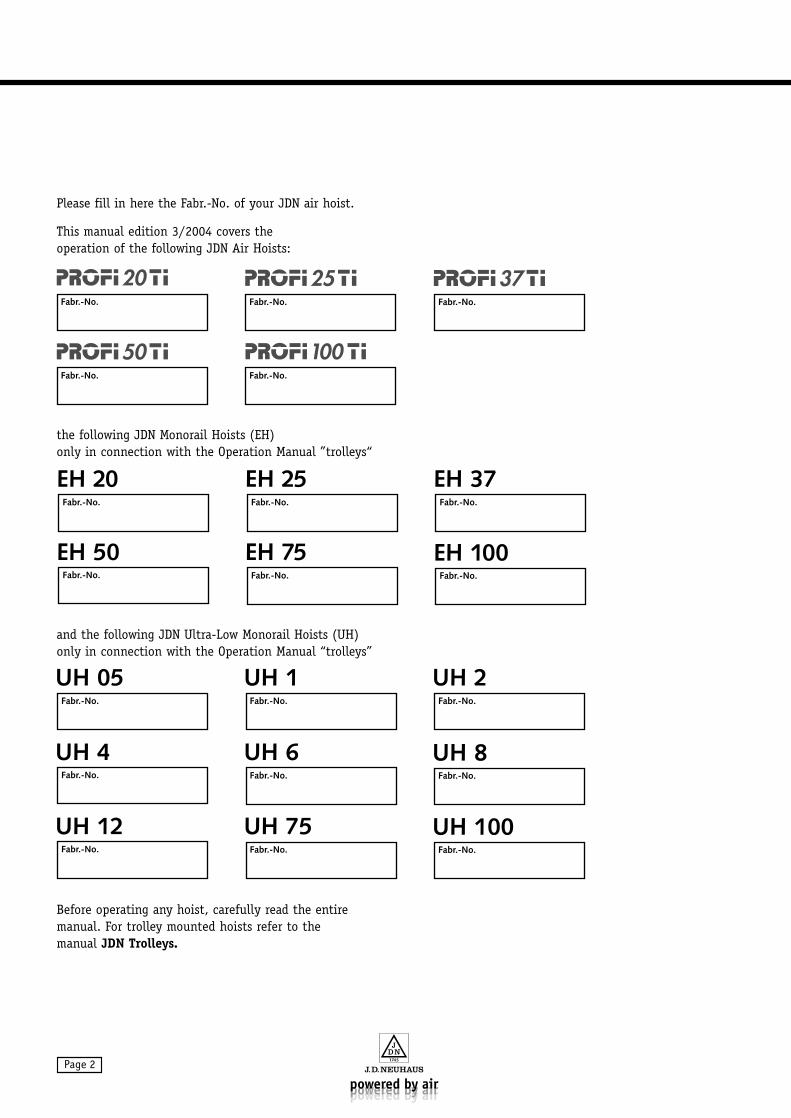
Please fill in here the Fabr.-No. of your JDN air hoist.
This manual edition 3/2004 covers theoperation of the following JDN Air Hoists:
the following JDN Monorail Hoists (EH) only in connection with the Operation Manual ”trolleys“
and the following JDN Ultra-Low Monorail Hoists (UH)only in connection with the Operation Manual “trolleys”
Before operating any hoist, carefully read the entiremanual. For trolley mounted hoists refer to the manual JDN Trolleys.
Fabr.-No.
25Fabr.-No.
20Fabr.-No.
Fabr.-No.
37
50Fabr.-No.
100
Fabr.-No. Fabr.-No.
Fabr.-No.
EH 20 EH 25Fabr.-No.
EH 37
Fabr.-No.
EH 100EH 50Fabr.-No.
EH 75
Fabr.-No. Fabr.-No.
Fabr.-No.
UH 05 UH 1Fabr.-No.
UH 2
Fabr.-No.
UH 8
Fabr.-No.
UH 100
UH 4
Fabr.-No.
UH 12
Fabr.-No.
UH 6
Fabr.-No.
UH 75
Page 3
CONTENTS
Organisational measures . . . . . . . . . . . . . . . . . . 5
Personnel safety . . . . . . . . . . . . . . . . . . . . . . . . 5
Preventing equipment damage . . . . . . . . . . . . . . 5
The operation manual . . . . . . . . . . . . . . . . . . . . 6
Warnings and symbols . . . . . . . . . . . . . . . . . . . 6
Identification . . . . . . . . . . . . . . . . . . . . . . . . . . 7
Operating mode . . . . . . . . . . . . . . . . . . . . . . . . 8
Explosion Protection . . . . . . . . . . . . . . . . . . . . . 8
Emission . . . . . . . . . . . . . . . . . . . . . . . . . . . . 13
Intended use . . . . . . . . . . . . . . . . . . . . . . . . . 13
Conditions of use . . . . . . . . . . . . . . . . . . . . . . 13
Certification . . . . . . . . . . . . . . . . . . . . . . . . . . 13
Application areas . . . . . . . . . . . . . . . . . . . . . . 14
Suspension points . . . . . . . . . . . . . . . . . . . . . . 14
Energy requirements . . . . . . . . . . . . . . . . . . . . 14
Transportation . . . . . . . . . . . . . . . . . . . . . . . . 15
Storage . . . . . . . . . . . . . . . . . . . . . . . . . . . . . 15
Unpacking . . . . . . . . . . . . . . . . . . . . . . . . . . . 16
Mounting . . . . . . . . . . . . . . . . . . . . . . . . . . . . 16
Installing the hoist . . . . . . . . . . . . . . . . . . . . . 16
Fastening the pendant control . . . . . . . . . . . . . 17
Connecting the main air supply . . . . . . . . . . . . 18
Initial operating checks . . . . . . . . . . . . . . . . . . 19
Safety instructions . . . . . . . . . . . . . . . . . . . . . 20
Operating materials . . . . . . . . . . . . . . . . . . . . . 23
Controls . . . . . . . . . . . . . . . . . . . . . . . . . . . . . 24
Chain . . . . . . . . . . . . . . . . . . . . . . . . . . . . . . . 25
Load hook . . . . . . . . . . . . . . . . . . . . . . . . . . . 26
Starting operation . . . . . . . . . . . . . . . . . . . . . . 26
Troubleshooting . . . . . . . . . . . . . . . . . . . . . . . 27
Care . . . . . . . . . . . . . . . . . . . . . . . . . . . . . . . . 28
Service unit . . . . . . . . . . . . . . . . . . . . . . . . . . 29
Checking the control elements . . . . . . . . . . . . . 33
Testing the brake function . . . . . . . . . . . . . . . . 33
Testing the limit switch . . . . . . . . . . . . . . . . . . 33
Lubrication of the chain . . . . . . . . . . . . . . . . . 34
Inspections and maintenance work . . . . . . . . . . 34
Maintenance list . . . . . . . . . . . . . . . . . . . . . . . 35
Inspection list . . . . . . . . . . . . . . . . . . . . . . . . 35
Test dimensions . . . . . . . . . . . . . . . . . . . . . . . 36
Chain container . . . . . . . . . . . . . . . . . . . . . . . 37
Filter silencer . . . . . . . . . . . . . . . . . . . . . . . . . 38
Overload protection . . . . . . . . . . . . . . . . . . . . . 39
Booster valve . . . . . . . . . . . . . . . . . . . . . . . . . 41
Axial bearing . . . . . . . . . . . . . . . . . . . . . . . . . 42
Technical data . . . . . . . . . . . . . . . . . . . . . . . . . 42
Dimensions . . . . . . . . . . . . . . . . . . . . . . . . . . 42
ANNEX
ACCESSORIES
MAINTENANCE
OPERATION
SETTING UP
TRANSPORTATION AND STORAGE
APPLICATION
PRODUCT INFORMATION
SAFETY INSTRUCTIONS
Please note!
Within the Federal Republic of Germanyoperators of air hoists must observe the currently applicable
UVV Winches, Lifting and Pulling Devices(BGV D8), and
UVV Load carrying Devices Used with LiftingEquipment (VBG 9a),
and users of trolley mounted hoists must additionallycomply with the currently applicable
UVV Cranes (BGV D6).
Users must also initiate the prescribed tests (see also“Principle for the Testing of Cranes“ BGG 905 (ZH1/27)).
In all other countries the user shall comply with localregulations as applicable.
Additional regulations may apply when incorporatingair hoists into other installations or using air hoists in unusual conditions.
Page 4
JDN Air Hoists/Monorail Hoists (in the following calledJDN Air Hoists) are manufactured in accordance withthe latest state of the art and accepted safety practice.Nonetheless, the use of an air hoist may be associatedwith the risk of injury or death of the user or of somethird party, or with the risk of property damage, if safetyrules are disregarded.
All personnel involved with the safe operation of the airhoist must carefully read and understand the operationmanual, especially the present section dealing withsafety. This is particularly important when personnelnot normally working with air hoists are charged with maintenance, repair or other additional works.
The user is obliged to ensure that the air hoist is operated in a safe manner. The following measures are requested as a minimum:
keep this manual readily available at the air hoist operating site,
carry out training on air hoist operation on a regular basis,
set up an inspection log and keep it up to date, and on a regular basis, check up on the personnel wor-
king with the air hoist to ensure that it is being usedin a safe and proper manner.
Ensure that only properly trained personnel are entrusted with the operation, maintenance and repairof the air hoist.
„Properly trained“ in the present case means that theoperator has appropriate training and experience inworking with air hoists and is sufficiently versed inoccupational safety and accident prevention regulationsto be able to determine whether or not it is safe to operate the air hoist.
Follow the applicable regulations for the workplace in question.
Observe all relevant accident prevention regulations,in particular BGV D8 (Winches, Lifting and PullingDevices) and VBG 9a (Load-carrying Devices Used withLifting Equipment).
Ensure that you are properly informed about anyhazardous materials you may be working with.
Follow the safety instructions given in this manual.
The user of JDN Air Hoists is responsible for ensuringthat the inspection log delivered with the hoist is correctly used and kept up to date.
Ensure that the scheduled maintenance is performedas prescribed.
Do not use the air hoist for any other purpose thanits intended design use.
Ensure that the conditions of use as detailed beloware met.
PREVENTING EQUIPMENT DAMAGE
PERSONNEL SAFETYORGANISATIONAL MEASURES
SAFETY INSTRUCTIONS
SAFETY INSTRUCTIONS
Page 5
The present manual is intended to help the operator to inform himself about JDN Air Hoists and how to usethem properly.
This manual contains important information on thesafe, proper, and economic operation of the JDN AirHoists. By following this information the risk of safetyhazards, repair costs and machinery downtime can bereduced and the useful lifetime of the air hoist can beextended.
Always keep the manual readily available at the locationwhere the JDN Air Hoist is being used.
All persons charged with operating, maintaining, orrepairing JDN Air Hoists must read and follow theinstructions in this manual.
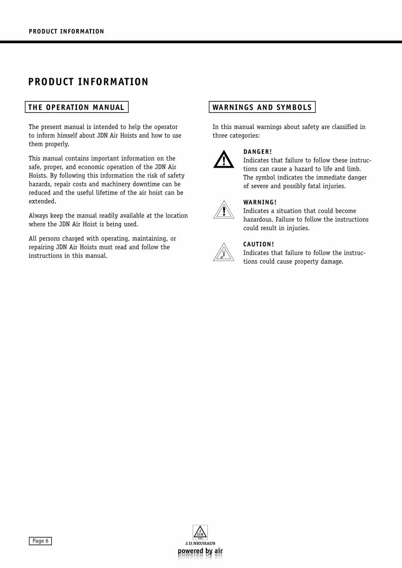
In this manual warnings about safety are classified inthree categories:
DANGER!Indicates that failure to follow these instruc-tions can cause a hazard to life and limb. The symbol indicates the immediate dangerof severe and possibly fatal injuries.
WARNING!Indicates a situation that could becomehazardous. Failure to follow the instructionscould result in injuries.
CAUTION!Indicates that failure to follow the instruc-tions could cause property damage.
WARNINGS AND SYMBOLSTHE OPERATION MANUAL
PRODUCT INFORMATION
PRODUCT INFORMATION
Page 6
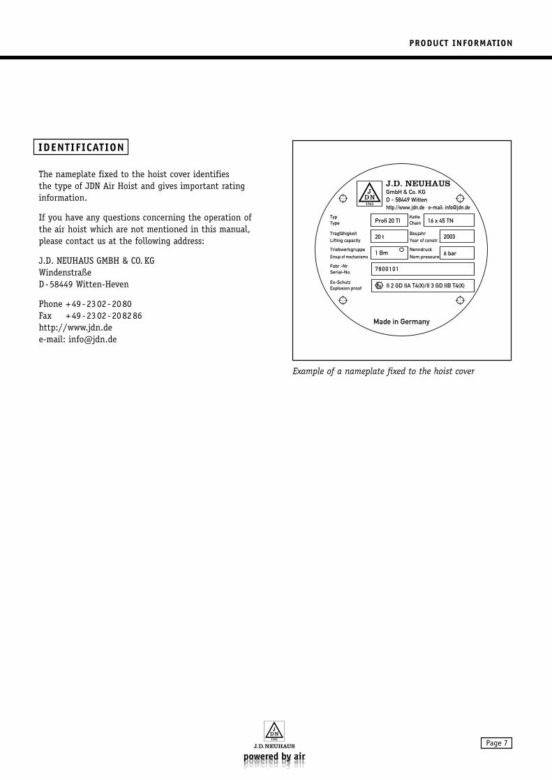
The nameplate fixed to the hoist cover identifies the type of JDN Air Hoist and gives important ratinginformation.
If you have any questions concerning the operation ofthe air hoist which are not mentioned in this manual,please contact us at the following address:
J.D. NEUHAUS GMBH & CO. KGWindenstraßeD-58449 Witten-Heven
Phone +49-2302-2080Fax +49-2302-208286http://www.jdn.dee-mail: [email protected]
Example of a nameplate fixed to the hoist cover
TypProfi 20 TI 16 x 45 TN
20 t
6 bar
2003
1 Bm
7800101
II 2 GD IIA T4(X)/II 3 GD IIB T4(X)
Type
J.D. NEUHAUSGmbH & Co. KGD - 58449 Wittenhttp.//www.jdn.de · e-mail: [email protected]
ChainKette
TragfähigkeitLifting capacity
Triebwerkgruppe
Group of mechanisms
BaujahrYear of constr.
Nenndruck
Nom.pressure
Fabr.-Nr.Serial-No.
Ex-SchutzExplosion proof
Made in Germany
IDENTIFICATION
PRODUCT INFORMATION
Page 7
PRODUCT INFORMATION
Page 8
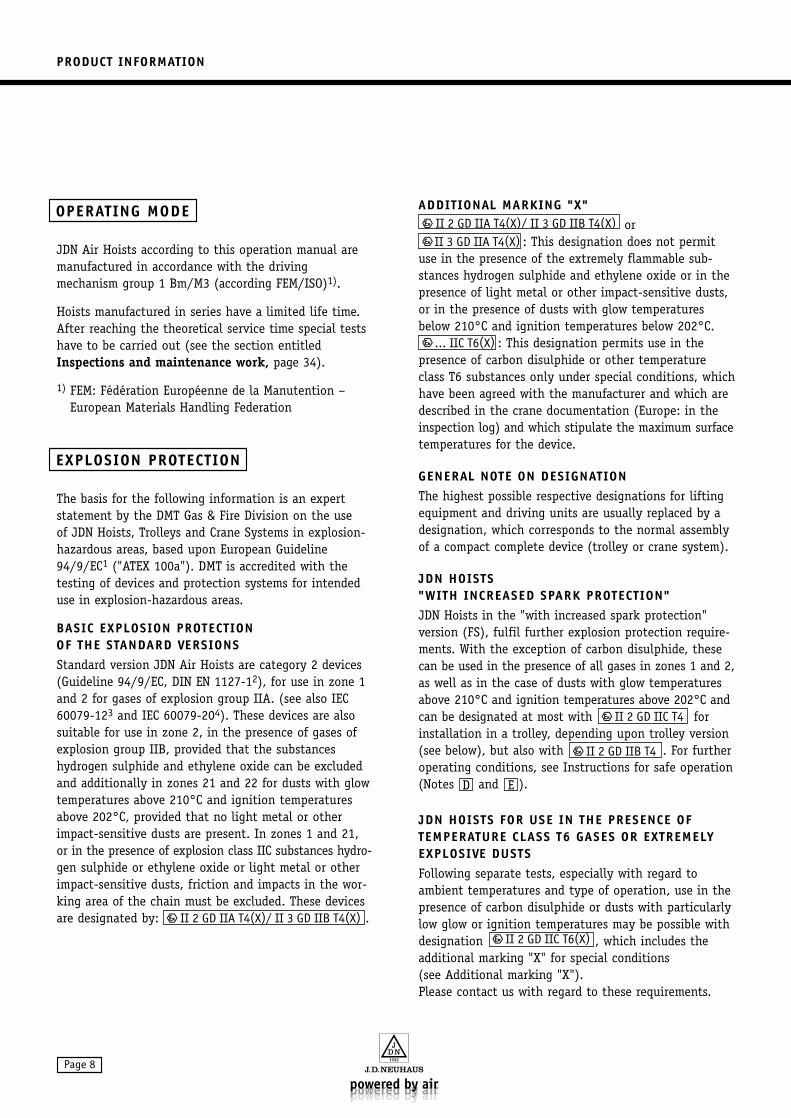
JDN Air Hoists according to this operation manual aremanufactured in accordance with the drivingmechanism group 1 Bm/M3 (according FEM/ISO)1).
Hoists manufactured in series have a limited life time.After reaching the theoretical service time special testshave to be carried out (see the section entitledInspections and maintenance work, page 34).
1) FEM: Fédération Européenne de la Manutention –European Materials Handling Federation
The basis for the following information is an expert statement by the DMT Gas & Fire Division on the use of JDN Hoists, Trolleys and Crane Systems in explosion-hazardous areas, based upon European Guideline94/9/EC1 ("ATEX 100a"). DMT is accredited with thetesting of devices and protection systems for intendeduse in explosion-hazardous areas.
BASIC EXPLOSION PROTECTION OF THE STANDARD VERSIONS Standard version JDN Air Hoists are category 2 devices(Guideline 94/9/EC, DIN EN 1127-12), for use in zone 1and 2 for gases of explosion group IIA. (see also IEC60079-123 and IEC 60079-204). These devices are alsosuitable for use in zone 2, in the presence of gases ofexplosion group IIB, provided that the substanceshydrogen sulphide and ethylene oxide can be excludedand additionally in zones 21 and 22 for dusts with glowtemperatures above 210°C and ignition temperaturesabove 202°C, provided that no light metal or otherimpact-sensitive dusts are present. In zones 1 and 21,or in the presence of explosion class IIC substances hydro-gen sulphide or ethylene oxide or light metal or otherimpact-sensitive dusts, friction and impacts in the wor-king area of the chain must be excluded. These devicesare designated by: .
ADDITIONAL MARKING "X"or
: This designation does not permituse in the presence of the extremely flammable sub-stances hydrogen sulphide and ethylene oxide or in thepresence of light metal or other impact-sensitive dusts,or in the presence of dusts with glow temperaturesbelow 210°C and ignition temperatures below 202°C.
: This designation permits use in the presence of carbon disulphide or other temperatureclass T6 substances only under special conditions, whichhave been agreed with the manufacturer and which aredescribed in the crane documentation (Europe: in theinspection log) and which stipulate the maximum surfacetemperatures for the device.
GENERAL NOTE ON DESIGNATIONThe highest possible respective designations for liftingequipment and driving units are usually replaced by adesignation, which corresponds to the normal assemblyof a compact complete device (trolley or crane system).
JDN HOISTS "WITH INCREASED SPARK PROTECTION"JDN Hoists in the "with increased spark protection" version (FS), fulfil further explosion protection require-ments. With the exception of carbon disulphide, thesecan be used in the presence of all gases in zones 1 and 2,as well as in the case of dusts with glow temperaturesabove 210°C and ignition temperatures above 202°C andcan be designated at most with forinstallation in a trolley, depending upon trolley version(see below), but also with . For furtheroperating conditions, see Instructions for safe operation(Notes and ).
JDN HOISTS FOR USE IN THE PRESENCE OF TEMPERATURE CLASS T6 GASES OR EXTREMELYEXPLOSIVE DUSTSFollowing separate tests, especially with regard toambient temperatures and type of operation, use in thepresence of carbon disulphide or dusts with particularlylow glow or ignition temperatures may be possible withdesignation , which includes theadditional marking "X" for special conditions (see Additional marking "X"). Please contact us with regard to these requirements.
ED
... IIC T6(X)
II 3 GD IIA T4(X)
EXPLOSION PROTECTION
OPERATING MODE
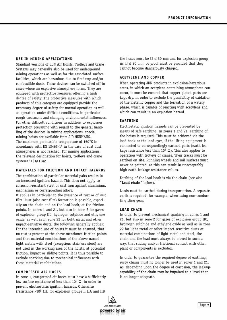
USE IN MINING APPLICATIONSStandard versions of JDN Air Hoists, Trolleys and CraneSystems may generally also be used for undergroundmining operations as well as for the associated surfacefacilities, which are hazardous due to firedamp and/orcombustible dusts. These devices can be switched off incases where an explosive atmosphere forms. They areequipped with protective measures offering a highdegree of safety. The protective measures with whichproducts of this category are equipped provide thenecessary degree of safety for normal operation as wellas operation under difficult conditions, in particularrough treatment and changing environmental influences.For other difficult conditions in addition to explosionprotection prevailing with regard to the general hand-ling of the devices in mining applications, specialmining hoists are available from J.D.NEUHAUS. The maximum permissible temperature of 150°C inaccordance with EN 13463-15 in the case of coal dustatmospheres is not reached. For mining applications,the relevant designation for hoists, trolleys and cranesystems is .
MATERIALS FOR FRICTION AND IMPACT HAZARDSThe combination of particular material pairs results inan increased ignition hazard. This does not apply tocorrosion-resistant steel or cast iron against aluminium,magnesium or corresponding alloys. It applies in particular to the presence of rust or of rustfilm. Rust (also rust film) formation is possible, especi-ally on the chain and on the load hook, at the frictionpoints. In zones 1 and 21, but also in zone 2 for gasesof explosion group IIC, hydrogen sulphide and ethyleneoxide, as well as in zone 22 for light metal and otherimpact-sensitive dusts, the following generally applies:For the intended use of hoists it must be ensured, thatno rust is present at the above-mentioned friction pointsand that material combinations of the above-namedlight metals with steel (exception: stainless steel) arenot used in the working area of the hoists, at potentialfriction, impact or sliding points. It is thus possible toexclude sparking due to mechanical influences withthese material combinations.
COMPRESSED AIR HOSESIn zone 1, compressed air hoses must have a sufficientlylow surface resistance of less than 109 Ω, in order toprevent electrostatic ignition hazards. Otherwise (resistance >109 Ω), for explosion groups I, IIA and IIB
the hoses must be ∅ ≤ 30 mm and for explosion groupiic ∅ ≤ 20 mm, or proof must be provided that theycannot become dangerously charged.
ACETYLENE AND COPPERWhen operating JDN products in explosion-hazardousareas, in which an acetylene-containing atmosphere canoccur, it must be ensured that copper-plated parts arekept dry, in order to exclude the possibility of oxidationof the metallic copper and the formation of a wateryphase, which is capable of reacting with acetylene andwhich can result in an explosion hazard.
EARTHINGElectrostatic ignition hazards can be prevented bymeans of safe earthing. In zones 1 and 21, earthing ofthe hoists is required. This must be achieved via theload hook or the load eyes, if the lifting equipment isconnected to correspondingly earthed parts (earth lea-kage resistance less than 106 Ω). This also applies tooperation with trolleys or cranes. Their tracks must beearthed on site. Running wheels and rail surfaces mustnever be painted, as this can result in unacceptablyhigh earth leakage resistance values.
Earthing of the load hook is via the chain (see also"Load chain" below).
Loads must be earthed during transportation. A separateearth is required, for example, when using non-conduc-ting sling gear.
LOAD CHAINIn order to prevent mechanical sparking in zones 1 and21, but also in zone 2 for gases of explosion group IIC,hydrogen sulphide and ethylene oxide as well as in zone22 for light metal or other impact-sensitive dusts ormaterial combinations of light metal and steel, thechain and the load must always be moved in such away, that sliding and/or frictional contact with otherplant or components is excluded.
In order to guarantee the required degree of earthing,rusty chains must no longer be used in zones 1 and 21.As, depending upon the degree of corrosion, the leakagecapability of the chain may be impaired to a level thatis no longer adequate.
PRODUCT INFORMATION
Page 9
PRODUCT INFORMATION
Page 10
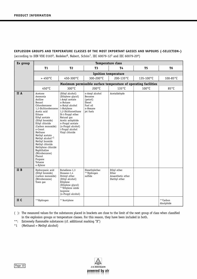
Ex group Temperature classT1 T2 T3 T4 T5 T6
Ignition temperature> 450°C 450-300°C 300-200°C 200-135°C 135-100°C 100-85°C
Maximum permissible surface temperature of operating facilities450°C 300°C 200°C 135°C 100°C 85°C
II A Acetone (Ethyl alcohol) n-Amyl alcohol AcetaldehydeAmmonia (Ethylene glycol) Benzene Aniline i-Amyl acetate (petrol)Benzol n-Butane DieselChlorobenzene n-Butyl alcohol Fuel oil1,2-Dichlorobenzene 1-Butylene n-HexaneAcetic acid 1,2-Dichloroethane jet fuelsEthane Di-i-Propyl etherEthyl acetate Natural gas(Ethyl bromide) Acetic anhydrideEthyl chloride n-Propyl acetate(Carbon monoxide) (n-Propyl alcohol)o-Cresol i-Propyl alcoholMethane Vinyl chlorideMethyl acetateMethyl alcohol*1Methyl bromideMethyl chlorideMethylene chlorideNaphthaline(Nitrobenzene)PhenolPropaneTolueneo-Xylene
II B Hydrocyanic acid Butadiene-1,3 Dimethylether Ethyl ether(Ethyl bromide) Dioxane-1,4 **Hydrogen Ether(carbon monoxide) Divinyl ether sulfide Anaesthetic ether(Nitrobenzene) (Ethyl alcohol) Diethyl etherTown gas Ethylene
(Ethylene glycol)**Ethylene oxideIsoprene(n-Propyl alcohol)
II C **Hydrogen **Acetylene **Carbondisulphide
EXPLOSION GROUPS AND TEMPERATURE CLASSES OF THE MOST IMPORTANT GASSES AND VAPOURS (-SELECTION-)(according to DIN VDE 01656, Redeker8, Nabert, Schön7, IEC 60079-123 and IEC 60079-204)
( ): The measured values for the substances placed in brackets are close to the limit of the next group of class when classifiedin the explosion groups or temperature classes. For this reason, they have been included in both.
**: Extremely flammable substances (cf. additional marking "X")*1 (Methanol = Methyl alcohol)
PRODUCT INFORMATION
Page 11
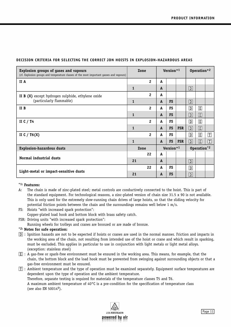
DECISION CRITERIA FOR SELECTING THE CORRECT JDN HOISTS IN EXPLOSION-HAZARDOUS AREAS
Explosion groups of gases and vapours Zone Version*1 Operation*2
(cf. Explosion groups and temperature classes of the most important gasses and vapours)
II A 2 A
1 A
II B (X) except hydrogen sulphide, ethylene oxide 2 A(particularly flammable) 1 A FS
II B 2 A FS
1 A FS
II C / T4 2 A FS
1 A FS FSR
II C / T6(X) 2 A FS
1 A FS FSR
Explosion-hazardous dusts Zone Version*1 Operation*2
Normal industrial dusts22 A
21 A
Light-metal or impact-sensitive dusts22 A FS
21 A FS D
D
D
TED
TED
ED
ED
ED
ED
D
D
*1: Features:A: The chain is made of zinc-plated steel; metal controls are conductively connected to the hoist. This is part of
the standard equipment. For technological reasons, a zinc-plated version of chain size 31.5 x 90 is not available.This is only used for the extremely slow-running chain drives of large hoists, so that the sliding velocity for potential friction points between the chain and the surroundings remains well below 1 m/s.
FS: Hoists "with increased spark protection":Copper-plated load hook and bottom block with brass safety catch.
FSR: Driving units "with increased spark protection": Running wheels for trolleys and cranes are bronzed or are made of bronze.
*2: Notes for safe operation:: Ignition hazards are not to be expected if hoists or cranes are used in the normal manner. Friction and impacts in
the working area of the chain, not resulting from intended use of the hoist or crane and which result in sparking,must be excluded. This applies in particular to use in conjunction with light metals or light metal alloys. (exception: stainless steel)
: A gas-free or spark-free environment must be ensured in the working area. This means, for example, that thechain, the bottom block and the load hook must be prevented from swinging against surrounding objects or that agas-free environment must be ensured.
: Ambient temperature and the type of operation must be examined separately. Equipment surface temperatures aredependent upon the type of operation and the ambient temperature. Therefore, separate testing is required for materials of the temperature classes T5 and T6.A maximum ambient temperature of 40°C is a pre-condition for the specification of temperature class (see also EN 500149).
T
E
D
PRODUCT INFORMATION
Page 12
TEMPERATURE LIMIT FOR EXPLOSION-HAZARDOUS DUSTSIn areas which are explosion-hazardous due to combu-stible dusts, the surface temperature must not exceedtwo-thirds of the ignition temperature in °C of thedust/air mixture. The temperatures of surfaces on whichhazardous deposits of combustible dusts can be formed,must not exceed the glow temperature of the relevantdust minus 75°K. Greater safety margins are required ifthickness of the dust layer exceeds 5 mm.
The corresponding surface temperatures can be derivedfrom the lowest values for glow and ignition tempera-tures of dusts specified in the HVBG/BIA Report 12/979
"Combustion and explosion characteristics of dusts":
Synthetic rubber, soot-containing:Glow temperature 220°C - 75°C = 145°C
max. permissiblesurface temperature
Stearic acid:Ignition temperature 190°C x 2/3 = 126°C
max. permissible surface temperature.
PLEASE ALSO OBSERVE YOUR CORRESPONDING NATIONAL REGULATIONS.
1 Richtlinie 94/9/EG des Europäischen Parlamentes und des Rates vom 23. März 1994 zur Angleichung derRechtsvorschriften der Mitgliedsstaaten für Geräte und Schutzsysteme zur bestimmungsgemäßen Verwendung in explosionsgefährdeten Bereichen
2 DIN EN 1127-1: Explosionsfähige Atmosphären - Explosionsschutz, Teil 1: Grundlagen und Methodik, 1997-10.
3 IEC 60079-12: Electrical apparatus for explosive gas atmospheres, Part 12: Classification of mixtures of gases andvapours with air according to their maximum experimental safe gaps and minimum igniting currents, 1978.
4 IEC 60079-20: Electrical apparatus for explosive gas atmospheres, Part 20: Data forflammable gases and vapours, relating to the use of electric apparatus, 1996-10.
5 EN 13463-1: Nichtelektrische Geräte für den Einsatz in explosionsgefährdeten Bereichen - Teil 1: GrundlegendeMethodik und Anforderungen
6 DIN VDE 0165: Errichten elektrischer Anlagen in explosionsgefährdeten Bereichen, 1991
7 Nabert, Schön: Sicherheitstechnische Kennzahlen brennbarer Gase und Dämpfe 2. Auflage,1978
8 Redeker, Schön: 6. Nachtrag zu Sicherheitstechnische Kennzahlen brennbarer Gase und Dämpfe, 1990
9 DIN EN 50014 (VDE 0170/0171 Teil 1): 2000-02Elektrische Betriebsmittel für explosionsgefährdete Bereiche: Allgemeine Bestimmungen
10 HVBG/BIA-Report 12/97: Hauptverband der Deutschen Berufsgenossenschaften/Berufsgenossenschaftliches Institut für Arbeitssicherheit
PRODUCT INFORMATION
Page 13
The sound emission figures are shown in tableTechnical data, page 43.The sound pressure level at the measuring surface at 1 mdistance from the machine surface was determined acc.to DIN 45635, Part 20 with an air pressure acc. to ourinstructions. The reduction of the sound level underindoor conditions is approx. 3 dB (A) per each doubleddistance.When in operation – due to motor lubrication – smallamounts of lubricating oil are discharged with theexhaust air into the ambient atmosphere.When using a filter silencer (see the section entitledOverload protection, page 40) the oil emission can beavoided. Additionally the sound emission will be reduced.
JDN Air Hoists are designed for lifting and loweringloads within the specified load-carrying capacities, with a vertically-arranged chain. In exceptional circum-stances, the lifting of personnel-carrying equipment isalso permitted. Please also observe the individual natio-nal regulations. In combination with trolleys, JDN AirHoists are also suitable for the floorless horizontalmovement of loads.
Any other use shall be deemed improper. Such improperuse is at the customer’s own risk, and the company J.D. NEUHAUS GMBH & CO. KG shall not be liable forany resulting damages.
Please also see Safety Instructions, page 21.
The JDN Air Hoists are sturdy and require very littlemaintenance. They are suitable for use in locations subject to explosion hazards, as well as locations expo-sed to soot, dust, humidity and extreme temperaturesbetween -20°C and approximately +70°C. Permittedchain and hook temperatures: -40°C up to +150°C.
WARNING!When touching metallic hand controls beingcolder than 0°C frostbites of the skin mayoccur within a few seconds, at temperaturesabove 55°C burnings may occur. Protectivemeasures: use suitable safety gloves.
Every JDN Air Hoist is issued with a works certificate.
CONDITIONS OF USE
INTENDED USE
EMISSION
-CERTIFICATION
APPLICATION
Page 14
Hoists intended for permanent outdoors operation mustbe protected against the influences of weather and theintervals between maintenance must be reduced.
DANGER!Suspension points for JDN Air Hoists are to be constructed in such a way that theexpected forces can be safely held. Ensure that your JDN Air Hoist can come free into alignment under load, otherwiseunallowed additional forces can occur.
DANGER!The supporting structure of air hoists musthave a rigid bedding. Vibrations damage the chain and may lead to chain cracks.Furthermore no vibrations must be trans-mitted from the outside to the hoist (as for example by the suspended load).
Air pressure, amounts and connections, see the tableentitled Technical data, page 43.
DETAILS OF THE AIR PRESSUREJDN Air Hoists are also identified by the nominal pressure (overpressure) stated on the hoist itself. With this value we want to coordinate the hoist to a corresponding air pressure system.
When connected but not working the hoist receives thepressure of the air circuit. After starting operation thepressure decreases to the actual value i.e. working pres-sure which varies according to the load figure and thedirection of the load movement (up or down).Furthermore it depends upon the hose section, the hoselength as well as upon the diameter of the air circuitand its length.
When calculating the lifting capacity of the hoists wehave therefore considered a loss of 10% of the nominalair pressure for lifting the maximum load. In otherwords: A hoist with a nominal pressure of 6 bar reachesthe stated parameters at a working pressure of 5.4 bar.
DANGER!Working with system pressures of more than6 bar may cause risks of overloading.Therefore the pressure has to be limited to 6 bar.
JDN Air Hoists must have sufficient supply of clean anddry working air (to fulfill this requirement an air dryermust, if necessary, be connected to the air supply).
Do not drive JDN Air Hoists with other gases (contactsupplier).
Working air must have sufficient of the followingqualities:
Solid particle content: Size of particles, smaller than 40 µm Density of particles, less than 5 mg/m3
Pressure dew point:At least 10°C under the lowest expected temperature insurrounding area of application.
For lubrication of the motor, the working air must contain lubricating oil in the following quantities:
Oil content: 10 mg per m3 air consumption
The adjustable oiler, which is built into the connectedair service unit, ensures that the operating air contains the required amount of oil (see the sectionentitled Service unit, page 30).
In working areas where the surrounding temperature is0°C or under and in case of longer periods of operation (e.g. several minutes) particular attention must be paidthat the working air is not too damp. Danger of icingup of air hoses, control valves, motor and brake!With the connection of an air dryer icing up can beavoided. Under certain conditions it is sufficient to feedlubricating oil with anti-freeze protection (see the sectionOperating materials, page 24) to the working air (see the section entitled Service unit, page 30).
ENERGY REQUIREMENTS
SUSPENSION POINTS
APPLICATION AREAS
APPLICATION
TRANSPORTATION AND STORAGE
Page 15
DANGER!Do not throw or drop your JDN Air Hoist.
Make sure that load hook, chain loops and control hosesdo not hang down.
Control hoses and switches must not be damaged when handling JDN Air Hoists.– Danger of incorrect functioning!
Store your JDN Air Hoist in a clean and dry place.
Take care that the control elements and control hosescannot be damaged.
Protect the connection for the air intake hose againstdamage or intake of dirt or foreign bodies.
In case of longer periods of non operation protect yourJDN Air Hoist including chain and load hook againstcorrosion. To protect the motor against corrosion injectconservating oil into the air supply hose after the lastuse (see the section entitled Operating materials,page 24), then run your JDN Air Hoist for a short period.
After longer periods of non operation clean the motorby pouring about 30 cm3 of petroleum into the air hoseand then run your JDN Air Hoist for approximately halfa minute. Then, straight away, pour a little lubricatingoil into the air hose – further lubrication is carried outby the service unit.
STORAGE
TRANSPORTATION
TRANSPORTATION AND STORAGE
SETTING UP
Page 16
WARNING!Be careful when unpacking the hoist. Observethe weight (see Technical Data, page 43)
CAUTION!Take care to prevent twisting the controlhoses which could lead to incorrect functioning of the hoist.
Keep the hoist documentation in the appropriateplace provided at site.
Carefully lift the hoist out of the carton (if existing). Recycle packaging materials in accordance
with local regulations.
The JDN Air Hoists are generally delivered in fully-assembled condition.
If not, then proceed to the sections entitled
Fastening the pendant control (page 18) Connecting the rope control (page 19) Chain container (page 38)
THE CHAIN MUST BE LUBRICATED BEFORE STARTING OPERATION (SEE PAGE 35).
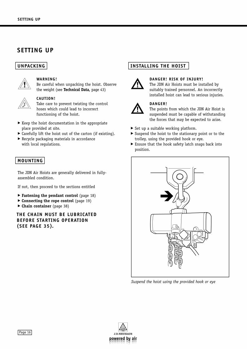
DANGER! RISK OF INJURY!The JDN Air Hoists must be installed bysuitably trained personnel. An incorrectly installed hoist can lead to serious injuries.
DANGER!The points from which the JDN Air Hoist issuspended must be capable of withstandingthe forces that may be expected to arise.
Set up a suitable working platform. Suspend the hoist to the stationary point or to the
trolley, using the provided hook or eye. Ensure that the hook safety latch snaps back into
position.
Suspend the hoist using the provided hook or eye
INSTALLING THE HOIST
MOUNTING
UNPACKING
SETTING UP
SETTING UP
Page 17
FASTENING THE COMPLETE PENDANT CONTROL TO THE HOISTFI control: First, fasten the hose carrier by unscrewing the cap
screw and screwing on the hose carrier.
E, F and HT controls: Hang up the loop of the wire rope into the
existing ring bolt.
CONNECTING THE CONTROL HOSESFor your help short hose pieces have been put into theplug-in connexion the colours of which correspond tothose of the hoses to be connected enabling you toconnect the hoses one after the other.
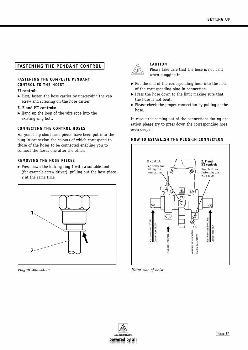
REMOVING THE HOSE PIECES Press down the locking ring 1 with a suitable tool
(for example screw driver), pulling out the hose piece2 at the same time.
CAUTION!Please take care that the hose is not bentwhen plugging in.
Put the end of the corresponding hose into the holeof the corresponding plug-in connection.
Press the hose down to the limit making sure thatthe hose is not bent.
Please check the proper connection by pulling at thehose.
In case air is coming out of the connections during ope-ration please try to press down the corresponding hoseeven deeper.
HOW TO ESTABLISH THE PLUG-IN CONNECTION
Motor side of hoist
FI control:Cap screw forfasting thehose carrier
E, F andHT control:Ring bolt for fastening thewire rope
Air
con
nect
ion
LIFT
ING
Cont
rol h
ose
GREE
N
Mai
n ai
r co
nnec
tion
Aux
iliar
y ai
r co
nnec
tion
Cont
rol h
ose
WH
ITE
Air
con
nect
ion
LOW
ERIN
G
Cont
rol h
ose
RED
Plug-in connection
2
1
FASTENING THE PENDANT CONTROL
SETTING UP
Page 18
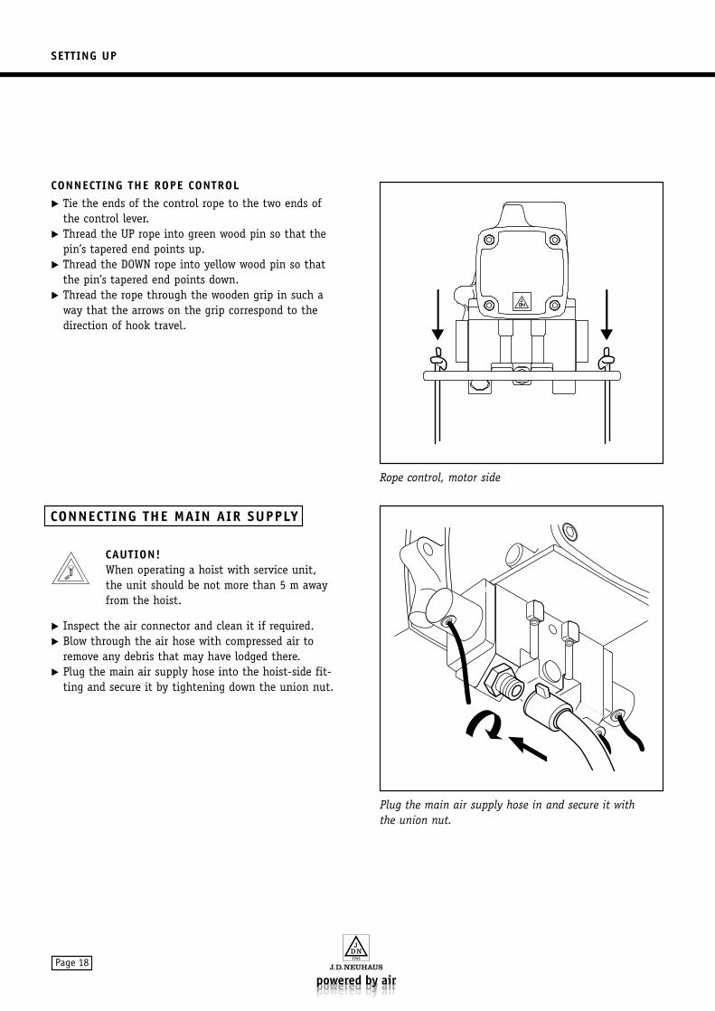
CONNECTING THE ROPE CONTROL Tie the ends of the control rope to the two ends of
the control lever. Thread the UP rope into green wood pin so that the
pin’s tapered end points up. Thread the DOWN rope into yellow wood pin so that
the pin’s tapered end points down. Thread the rope through the wooden grip in such a
way that the arrows on the grip correspond to thedirection of hook travel.
CAUTION!When operating a hoist with service unit, the unit should be not more than 5 m awayfrom the hoist.
Inspect the air connector and clean it if required. Blow through the air hose with compressed air to
remove any debris that may have lodged there. Plug the main air supply hose into the hoist-side fit-
ting and secure it by tightening down the union nut.
Plug the main air supply hose in and secure it with the union nut.
Rope control, motor side
CONNECTING THE MAIN AIR SUPPLY
SETTING UP
Page 19
Prior to initial use the hoist and supporting structuremust be checked by a qualified person. Hoists in trol-leys, monorail hoists and ultra-low monorail hoists haveto be checked by an authorised person. Checking mustalso be carried out after any major modification. Theobject of such testing is to determine that the liftingequipment is correctly installed and ready for operation.
TESTING THE BRAKEThe correct functioning of the brake must be testedbefore starting to use the hoist. Proceed as follows:
Operate the hoist with no load, alternating betweenlifting and lowering.
The chain must stop running immediately after relea-sing a control button.
DANGER!If you notice that the chain running doesnot stop immediately stop using the hoist atonce! The hoist must be repaired before anyfurther use.
CHECKING THE DIRECTION OF OPERATION Check that the load hook moves up and down in
accordance with the markings on the hoist controls.
CHECKING THE OVERRUN PROTECTION Lift the load hook with no load until it almost
reaches the upper end. Carefully lift it still further until the hook or the
chain stop strikes the overrun switch.
The lifting operation must stop when the control leverhas reached its central position.
DANGER!In case the hoisting movement is not stoppedwith the control lever in its central positionand the control lever blocks in the downposition, stop using the hoist at once ! The hoist must be repaired before any further use.
CHECKING THE EMERGENCY STOP SWITCH Actuate lifting process and press down red emergency
stop switch whilst lever is still pressed down. Liftingprocess must come to a halt immediately. Releaseemergency stop switch.
Actuate lowering process and press down red emer-gency stop switch whilst lever is still pressed down.Lowering process must come to a halt immediately.Release emergency stop switch.
INITIAL OPERATING CHECKS
OPERATION
Page 20
FOLLOW THESE RULES FOR SAFE HOIST OPERATION
Whenever you operate a hoist, you are responsible foryour own safety and the safety of your fellow workers.
Only persons duly authorised by the managementshall operate the hoist.
Before beginning to use the JDN Air Hoist you shouldinform yourself thoroughly about the correct methodof operation. Read this manual carefully and carry outthe indicated procedures on the hoist step by step.
Report any malfunctioning to your safety representa-tive at once, so that it can be corrected.
Follow the instructions issued by the responsible acci-dent prevention authorities (in Germany, theseinstructions are known as UVV’s and are issued by thetrade associations).
As a prerequisite for proper use the instructions in theoperation manual must be observed and the recommen-ded inspection and maintenance procedures must becarried out.
Hoists have to be checked by trained staff at least oncea year or after a service time of 160 hours (see the sec-tion entitled Inspections and maintenance work,page 34).
In addition to the annual inspection by an expert JDN Air Hoists should be checked according to the service and inspection lists (see the sections entitledMaintenance list and Inspection list, page 35).
For example JDN Air Hoists may not be used in the following areas:
critical surroundings in atomic plants. above acid baths or similar plants with aggressive
substances. in areas where organic acids can be found. operating the hoist whilst lying on the floor or
moving loads horizontally.
On the following pages some important points for thesafe operation of your JDN Air Hoist are listed. Theyshould help you to avoid hazards.
Improper use includes but is not limited to any andall of the following:
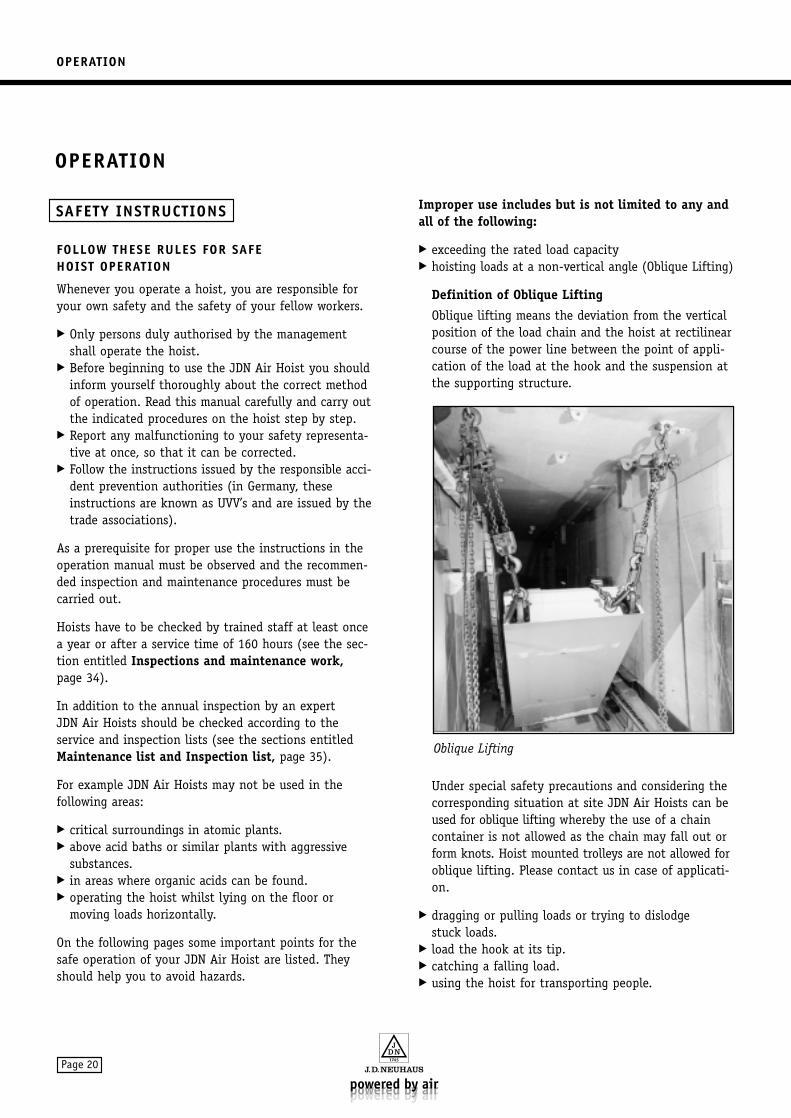
exceeding the rated load capacity hoisting loads at a non-vertical angle (Oblique Lifting)
Definition of Oblique Lifting
Oblique lifting means the deviation from the verticalposition of the load chain and the hoist at rectilinearcourse of the power line between the point of appli-cation of the load at the hook and the suspension atthe supporting structure.
Under special safety precautions and considering thecorresponding situation at site JDN Air Hoists can beused for oblique lifting whereby the use of a chaincontainer is not allowed as the chain may fall out orform knots. Hoist mounted trolleys are not allowed foroblique lifting. Please contact us in case of applicati-on.
dragging or pulling loads or trying to dislodge stuck loads.
load the hook at its tip. catching a falling load. using the hoist for transporting people.
Oblique Lifting
SAFETY INSTRUCTIONS
OPERATION
OPERATION
Page 21
hoisting by tipping the control buttons or levers overlonger lifting distances.
reversing the hoist while it is in motion. deliberately ramming the end stop switch.
For the safety of all personnel it is vital to follow the instructions given below whenever operating a JDN Air Hoist.
Never touch a running chain. Never allow any person to stay under a raised/sus-
pended load. When hooking loads observe appropriate regulations. Make sure that the operating place is without any
danger for the operator due to suspension or load. Start carefully when lifting loads. Never try to correct a fault or damage while the hoist
is under load. Never operate the hoist whilst lying on the floor or
move loads horizontally. Never run to end positions under normal working
conditions. Never use bent, open or twisted hooks.
Hoist to repair, never straighten, change hook. Never use stiff moving hook at the chain. Inspection. Never use stiff moving hook in the housing without
load. Inspection. Never load hook on the tip, only on deepest part of
hook saddle. Never lock hook at connecting point. Never anneal the hook. Never block operating elements. Never use stiff operating elements. Repair shop. Operate JDN Air Hoists only with original JDN con-
trols. Uncontrollable external power influences
(e.g. through hydrocylinder, falling loads) are notpermitted.1
Use only suitable and approved harness, do not jamhook at the fixing point of the harness.
Never use the hoist chain for wrapping around a loadto be lifted.
Position the load vertically under the hoist before lifting. The chain should be hanging straight down.
Never allow a load to drop into the harness. Before lifting a load, ensure that it does not exceed
the rated capacity of the hoist including the weightof the load and the harness.
Do not take up the load at full speed if the chain isinitially slack.
Ensure that the load is in a stable position when lif-ting or lowering it down to avoid accidents caused bya toppling or falling load.
Never use the hoist in an attempt to dislodge a loadthat has become stuck.
Never lift more than one load at a time. Never allow the chain to be bent. Save the load in case of loss of energy. Do not join or mend hoist chain. Exchange deformed load hook. Repair damaged hook safety latch. Repair tight hook bearing. Do not bend or squeeze control hoses. Loose screws must be fastened by repair shop. Shut off air supply before taking off air hoses. Do not exceed allowed quantity of chain
in the chain container. When working without chain container avoid dangers
caused by the idle chain: falling down, interlocking,striking (see section Chain Container, page 38).
Repair hoist in case of a too long braking distance. Check blocked chain for damages. Check chain for damage if hoist blocks in switched
on position. In case of lifting a load with several hoists avoid
overloading by wrong load distribution. Avoid unacceptable load distribution.
Choose safe place of control. Do not exceed operating pressure. Put in order twisted chain (capsized bottom block). Do not work with damaged or worn or rusty chain. Do not work with chain pulled rigid, bent or
extended chain. Do not use the load chain as a sling for suspension. It is not permitted to connect or repair hoist chains
(e.g. with bolts, emergency links or otherwise). Remove chain accumulated in front of chain intake. Do not bend the chain. Admissible temperature range for chain and hook:
-40°C up to +150°C, permitted heat bearing capacityof the body of the air hoist max. 90 °C, permittedambient temperature: -20°C up to +70°C.
Never touch metallic hand controls being colder than0°C or warmer than 43°C without using suitablesafety gloves.
OPERATION
Page 22
Do not carry out any modifications on the air hoist. It is not allowed to use other than JDN components
with JDN Air Hoists because of the dangers connectedtherewith.
Only use original JDN spare parts. When using foreigncomponents and/or carrying out changes by non authorised persons J.D. Neuhaus GmbH & Co. KG doesnot undertake any responsilbility.
If the air supply is cut protect area around the loaduntil power is restored.
Turn off the compressed air before detaching the airhoist from the compressed air system.
Do not start a double or multiple fall chain hoistwhen the bottom block is still supported.
DANGER!Make sure that the load hook can be loweredup to the floor at all operating conditions ofthe air hoist in order to avoid that a load islowered to its lowest position without rea-ching the floor. Danger of overloading.
In case of using hoists in extremely difficult conditionsthe user has to work out a directive on the basis of thisOperation Manual understandable for and in the languageof the operator. In this directive regulations for the safeoperation are stipulated considering the special conditi-ons at site.
In addition, it is essential to follow all instructionsgiven in the sections entitled Intended use andConditions of use, page 14.
JDN Air Hoists are equipped with round steel chains asload chains. When in use section 5 of DIN 685 should beobserved.
Extract: “At the instigation of the operator chains inuse should be checked and tested at regular intervals bya responsable expert” (see the section entitledInspection list, page 36).
OPERATION
Page 23
FOR MOTOR LUBRICATION: lubricating oil ”D” (pneumatic oil), DIN 51502,
kinematic viscosity approx. 32 mm2/s (cST) at 40°C(ISO VG 32, DIN 51519).
Additives: Anticorrosive, wear protection and cleaning
If surrounding temperatures are 0°C or below andaccording to the humidity of the pressurised air ananti-freeze additive to the lubricating oil or pneumaticoil with anti-freeze additive for the appropriatetemperatures is recommended.
WARNING!Oil and grease may cause skin irritation.Wear protective gloves at all times.
CAUTION!Risk of motor damage! Never mix syntheticoil with mineral oil as the physical and ther-mal properties may be adversely affected.
If a service unit is in use no synthetic lubricants shouldbe used at all. Do not use alcohol-based products foranti-icing protection.
FOR MOTOR PRESERVATION: Use a non resinous and non sticking conserving oil.
The preservation protection duration should be inaccordance with the intended period of non operation.
FOR LUBRICATION OF BEARINGS AND GEAR: Roller bearing grease, lithium saponified, walk pene-
tration 265–295 (0.1 mm). Dropping point: 190°C.
Operable temperature range: -30°C to +130°C, groundoil viscosity at 40°C 190 mm2/s, DIN 51502, additives:anticorrosive and ageing protection.
FOR MOTOR CLEANING: Pure petroleum.
FOR CHAIN LUBRICATION: Motor oil, kinematic viscosity
approx. 150 mm2/s (cST) at 40°C.
If the environmental conditions at the working site aresuch that they induce wear please consult the manufac-turer about the appropriate motor and chain lubricant.
OPERATING MATERIALS
OPERATION
Page 24
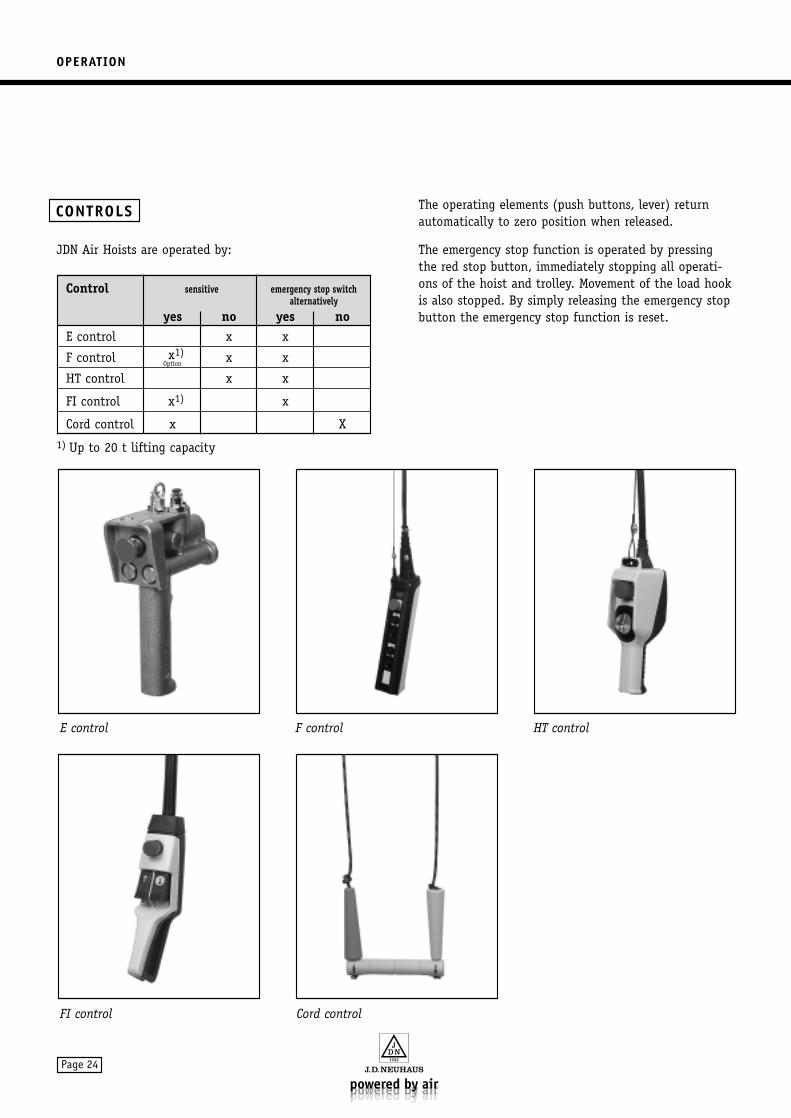
JDN Air Hoists are operated by:
1) Up to 20 t lifting capacity
The operating elements (push buttons, lever) returnautomatically to zero position when released.
The emergency stop function is operated by pressingthe red stop button, immediately stopping all operati-ons of the hoist and trolley. Movement of the load hookis also stopped. By simply releasing the emergency stopbutton the emergency stop function is reset.
CONTROLS
FI control Cord control
E control F control HT control
Control sensitive emergency stop switchalternatively
yes no yes noE control x x
F control x1) x x
HT control x x
FI control x1) x
Cord control x X
Option
OPERATION
Page 25
RULES FOR RUNNING IN HOIST CHAINS BEFORE CARRYING OUT THE OVERLOAD TEST
CAUTION!In case this information should not be observed you damage the high tensile chainin your hoist/lifting gear already duringtesting prior to initial use for which themanufacturer does not undertake any liability.
Hoisting chains with a load capacity of over 25 metrictons have to be run in before carrying out the overloadtest so that they can withstand the high surface pressureat the contact points of the chain links (in the joints).
For preparing the test with overload the following pre-requisites have to be fulfilled:
1. The chain has to be carefully lubricated in the joints.Please observe the relevant information in theOperation Manual.
2. The chain has to be loaded five times by lifting andlowering with approximately 50% the nominal loadthus sufficiently increasing the load bearing capacityof the joints.
3. Especially the part of the chain which will be testedwith overload has to be carefully lubricated onceagain.
Only now the overload test can be carried out.
DANGER!Extreme corrosions (pitting corrosion) heavily reduces the resistance against vibra-tions of chains. Danger of cracks!Hydrogen induced brittleness with followingstress corrosion cracking due to corrodingmedia (as for example sea water) can occurat high tensile steels (as for example at thechain). Danger of cracks!
So-called recombination poisons as for example hydro-gen sulphide, cyanides, arsenic compounds and rhoda-nides favour this procedure.
Furthermore dangers arise due to rusty chains whenusing chain containers as the chain may fall out of thebox when piling up.
Apart from that rusty chains increase wear.Protect the chain against corrosion.Before operation ensure that the chain of your JDN AirHoist is in perfect condition.
Order any twisted chain. Ensure that the chain can run straight so that
blocking of the chain intake at the mid section is avoided.
The chain has to be checked in regular intervals (see the section entitled Inspection list, page 36)
In case of any of the following defects: Extended chain links Bent chain links Externally damaged links Chain pulled rigid Severe wear in the link joints Corrosion scarsthe JDN Air Hoist must be sent for overhaul immediately(see the section entitled Test dimensions, page 37).
The chain must be lubricated when not under load (see the section entitled Lubrication of the chain,page 35).
Appropriate lubricants see the section entitledOperating materials, page 24.
The lubrication intervals depend on the dailyrunning time.
Increased wear can occur due to aggressiveenvironmental influences.
Shorten maintenance intervals.
For safety reasons please note that the chain may not be
used as a sling round the load for suspension. handled while running. run at an angle so that the links can be bent on entry. repaired or attached to other hoist chains
(e.g. with bolts, emergency links or otherwise).
The allowed chain temperature range is from–40°C to +150°C.
If you use a chain container the permitted filling capacity may not be exceeded (see the section entitledChain container, page 38).
CHAIN
OPERATION
Page 26
Check the throat width “a” and the height “h” of theload hook of the JDN Air Hoist in use at least once ayear (see the section entitled Test dimensions, page 37).
Load hooks may not be Loaded on the tip Straightened Annealed
If the hook is bent the JDN Air Hoist should be sent forinspection.
The allowed load hook temperature range is from–40°C to +150°C.
JDN Air Hoists including their supporting structure areto be checked by trained staff prior to being placed inservice.
In case JDN Hoists are mounted by the user into trolleysor cranes, these powered cranes have to be checked bytrained staff prior to being placed in service or prior tobeing placed in service again after a substantial modifi-cation.
For preparation of the compressed air JDN Air Hoistsmust be operated with an air service unit. The air service unit must not be more than 10 m awayfrom the hoist.
The air service unit is supplied without the oil.Oiler and regulator are already preset.
For filling the oiler, see the sections entitled Operatingmaterials, page 24, and Service unit, page 30.
Lubrication of the chain by the client before initial useis especially important (see the sections entitledLubrication of the chain, page 35, and Operating materials, page 24).
A well ordered running-in of the chain is a must for aproper functioning of the JDN Air Hoist. Before everyoperation, please check that the chain is not twisted orthe bottom block – if applicable – has not been flippedthrough the chain falls. Order the chain if necessary.
Observe all appropriate regulations when attaching the load!
Before every operation and after longer idle periodsaction should be taken in the following order:
1. Check power requirements (air pressure and air consumption see the section entitled Technical data,page 43) and the setting of the regulator in the service unit.
2. Check the oil level in the oiler of the service unitand if necessary replenish (see the section entitledService unit, page 30).
3. Lubricate the chain if necessary.
4. Blow through the air hose before connecting.
5. Connect air supply hose (for size of hose and airconnection screw see the section entitled Technicaldata, page 43).
6. Test the brake function and – at the same time – the control unit and the limit switch (see the sectionentitled Testing the limit switch, page 34).
Switch the JDN Air Hoist (without load) for short periodsalternatively to raise and lower. When the control elementis released the chain should not continue to run. If the chain continues to run and/or the operating element does not automatically return to the zero position, your JDN Air Hoist must be sent for repair!
STARTING OPERATION
LOAD HOOK
OPERATION
Page 27
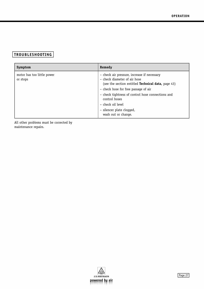
All other problems must be corrected bymaintenance repairs.
TROUBLESHOOTING
Symptom Remedy
motor has too little power – check air pressure, increase if necessaryor stops – check diameter of air hose
(see the section entitled Technical data, page 43)
– check hose for free passage of air
– check tightness of control hose connections and control hoses
– check oil level
– silencer plate clogged,wash out or change.
MAINTENANCE
Page 28
If maintenance measures exceed care and servicing please contact the manufacturer.
With regard to the qualification of maintenance personnel see the section entitled Safety instructions,page 5.
If your JDN Air Hoist is not suspended, connected orinstalled stationary but frequently changing workingplace – especially in contaminated or humid surroun-dings – ensure that for periods of non operation it isstored in a clean and dry place (see the section entitledStorage, page 16).
CARE
MAINTENANCE
MAINTENANCE
Page 29
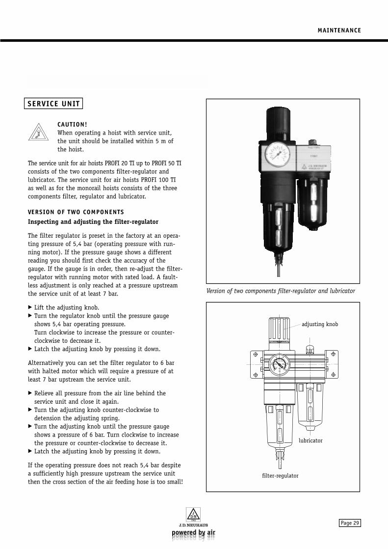
CAUTION!When operating a hoist with service unit, the unit should be installed within 5 m ofthe hoist.
The service unit for air hoists PROFI 20 TI up to PROFI 50 TIconsists of the two components filter-regulator andlubricator. The service unit for air hoists PROFI 100 TIas well as for the monorail hoists consists of the threecomponents filter, regulator and lubricator.
VERSION OF TWO COMPONENTSInspecting and adjusting the filter-regulator
The filter regulator is preset in the factory at an opera-ting pressure of 5,4 bar (operating pressure with run-ning motor). If the pressure gauge shows a differentreading you should first check the accuracy of thegauge. If the gauge is in order, then re-adjust the filter-regulator with running motor with rated load. A fault-less adjustment is only reached at a pressure upstreamthe service unit of at least 7 bar.
Lift the adjusting knob. Turn the regulator knob until the pressure gauge
shows 5,4 bar operating pressure.Turn clockwise to increase the pressure or counter-clockwise to decrease it.
Latch the adjusting knob by pressing it down.
Alternatively you can set the filter regulator to 6 barwith halted motor which will require a pressure of atleast 7 bar upstream the service unit.
Relieve all pressure from the air line behind the service unit and close it again.
Turn the adjusting knob counter-clockwise to detension the adjusting spring.
Turn the adjusting knob until the pressure gaugeshows a pressure of 6 bar. Turn clockwise to increasethe pressure or counter-clockwise to decrease it.
Latch the adjusting knob by pressing it down.
If the operating pressure does not reach 5,4 bar despitea sufficiently high pressure upstream the service unitthen the cross section of the air feeding hose is too small!
adjusting knob
lubricator
filter-regulator
Version of two components filter-regulator and lubricator
SERVICE UNIT
MAINTENANCE
Page 30
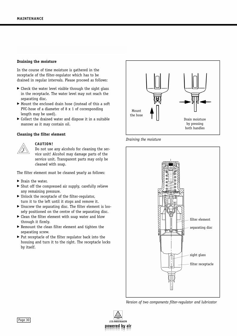
Draining the moisture
In the course of time moisture is gathered in thereceptacle of the filter-regulator which has to be drained in regular intervals. Please proceed as follows:
Check the water level visible through the sight glassin the receptacle. The water level may not reach theseparating disc.
Mount the enclosed drain hose (instead of this a softPVC-hose of a diameter of 8 x 1 of correspondinglength may be used).
Collect the drained water and dispose it in a suitablemanner as it may contain oil.
Cleaning the filter element
CAUTION!Do not use any alcohols for cleaning the ser-vice unit! Alcohol may damage parts of theservice unit. Transparent parts may only becleaned with soap.
The filter element must be cleaned yearly as follows:
Drain the water. Shut off the compressed air supply, carefully relieve
any remaining pressure. Unlock the receptacle of the filter-regulator,
turn it to the left until it stops and remove it. Unscrew the separating disc. The filter element is loo-
sely positioned on the centre of the separating disc. Clean the filter element with soap water and blow
through it firmly. Remount the clean filter element and tighten the
separating screw. Put receptacle of the filter regulator back into the
hosuing and turn it to the right. The receptacle locksby itself.
Version of two components filter-regulator and lubricator
filter element
separating disc
sight glass
filter receptacle
Draining the moisture
Mountthe hose
Drain moistureby pressing
both handles
MAINTENANCE
Page 31
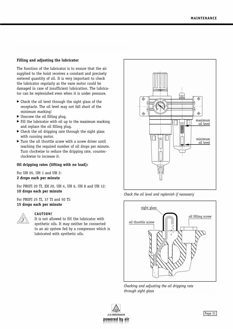
Filling and adjusting the lubricator
The function of the lubricator is to ensure that the airsupplied to the hoist receives a constant and preciselymetered quantity of oil. It is very important to checkthe lubricator regularly as the vane motor could bedamaged in case of insufficient lubrication. The lubrica-tor can be replenished even when it is under pressure.
Check the oil level through the sight glass of thereceptacle. The oil level may not fall short of theminimum marking!
Unscrew the oil filling plug. Fill the lubricator with oil up to the maximum marking
and replace the oil filling plug. Check the oil dripping rate through the sight glass
with running motor. Turn the oil throttle screw with a screw driver until
reaching the required number of oil drops per minute.Turn clockwise to reduce the dripping rate, counter-clockwise to increase it.
Oil dripping rates (lifting with no load):
For UH 05, UH 1 and UH 2:2 drops each per minute
For PROFI 20 TI, EH 20, UH 4, UH 6, UH 8 and UH 12:10 drops each per minute
For PROFI 25 TI, 37 TI and 50 TI:15 drops each per minute
CAUTION!It is not allowed to fill the lubricator withsynthetic oils. It may neither be connectedto an air system fed by a compressor which islubricated with synthetic oils.
Checking and adjusting the oil dripping ratethrough sight glass
sight glass
oil throttle screw
oil filling screw
Check the oil level and replenish if necessary
maximumoil level
minimumoil level
MAINTENANCE
Page 32
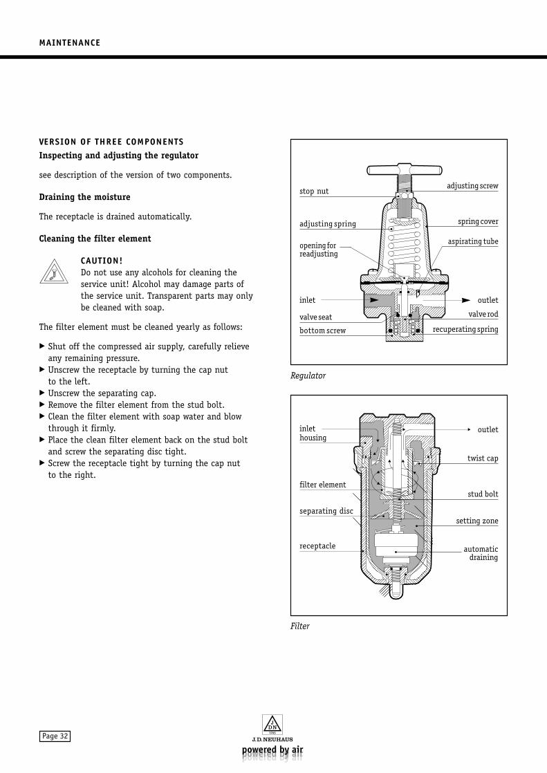
VERSION OF THREE COMPONENTSInspecting and adjusting the regulator
see description of the version of two components.
Draining the moisture
The receptacle is drained automatically.
Cleaning the filter element
CAUTION!Do not use any alcohols for cleaning the service unit! Alcohol may damage parts ofthe service unit. Transparent parts may onlybe cleaned with soap.
The filter element must be cleaned yearly as follows:
Shut off the compressed air supply, carefully relieveany remaining pressure.
Unscrew the receptacle by turning the cap nut to the left.
Unscrew the separating cap. Remove the filter element from the stud bolt. Clean the filter element with soap water and blow
through it firmly. Place the clean filter element back on the stud bolt
and screw the separating disc tight. Screw the receptacle tight by turning the cap nut
to the right.
Filter
Regulator
QQQQ
QQQQQQ
QQQQQQQQ
QQQQQQQQ
QQQQQQQ
QQQQQ
QQQ
¢¢
¢¢¢¢
¢¢¢¢¢¢
¢¢¢¢¢¢¢¢
¢¢¢¢¢¢¢¢
¢¢¢¢¢¢¢
¢¢¢¢¢
¢¢¢
QQQQ
QQQQQQ
QQQQQQQ
QQQQQQ
QQQQQ
QQQ
¢¢
¢¢¢¢
¢¢¢¢¢¢
¢¢¢¢¢¢¢
¢¢¢¢¢¢
¢¢¢¢¢
¢¢¢
QQQ
¢¢
¢¢¢
QQ¢¢
¢¢
¢¢
¢¢
¢¢
QQQ
¢¢¢
¢¢
QQQ
QQQQ
¢¢¢
¢¢¢¢
¢¢Q¢
QQQ
¢¢¢
valveseat •
stop nut •
adjusting spring•
opening forreadjusting
inlet
bottom screw•
• adjustingscrew
• springcover
aspirating tube
• valve rod
•recuperatingspring
•
•
outlet
inlethousing
•
filter element•
separating disc•
receptacle•
outlet
• twist cap
• stud bolt
•setting zone
• automaticdraining
MAINTENANCE
Page 33
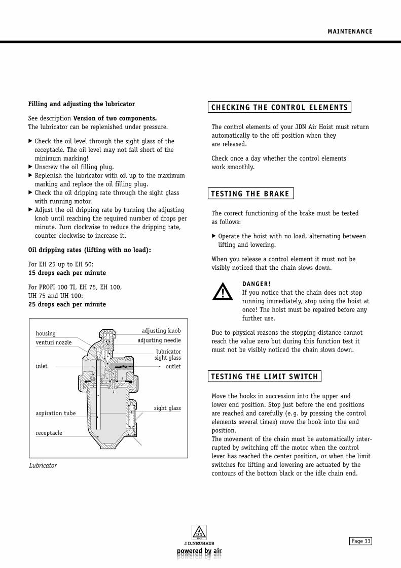
Filling and adjusting the lubricator
See description Version of two components.The lubricator can be replenished under pressure.
Check the oil level through the sight glass of thereceptacle. The oil level may not fall short of theminimum marking!
Unscrew the oil filling plug. Replenish the lubricator with oil up to the maximum
marking and replace the oil filling plug. Check the oil dripping rate through the sight glass
with running motor. Adjust the oil dripping rate by turning the adjusting
knob until reaching the required number of drops perminute. Turn clockwise to reduce the dripping rate,counter-clockwise to increase it.
Oil dripping rates (lifting with no load):
For EH 25 up to EH 50:15 drops each per minute
For PROFI 100 TI, EH 75, EH 100, UH 75 and UH 100:25 drops each per minute
The control elements of your JDN Air Hoist must returnautomatically to the off position when they are released.
Check once a day whether the control elements work smoothly.
The correct functioning of the brake must be tested as follows:
Operate the hoist with no load, alternating betweenlifting and lowering.
When you release a control element it must not be visibly noticed that the chain slows down.
DANGER!If you notice that the chain does not stoprunning immediately, stop using the hoist atonce! The hoist must be repaired before anyfurther use.
Due to physical reasons the stopping distance cannotreach the value zero but during this function test itmust not be visibly noticed the chain slows down.
Move the hooks in succession into the upper and lower end position. Stop just before the end positionsare reached and carefully (e.g. by pressing the controlelements several times) move the hook into the endposition.The movement of the chain must be automatically inter-rupted by switching off the motor when the controllever has reached the center position, or when the limitswitches for lifting and lowering are actuated by thecontours of the bottom black or the idle chain end.
TESTING THE LIMIT SWITCH
TESTING THE BRAKE
CHECKING THE CONTROL ELEMENTS
Lubricator
•adjusting knob
outlet
venturi nozzle
inlet
aspiration tube•
receptacle•
•adjusting needle
• lubricatorsight glass
•
housing
•
•sight glass
MAINTENANCE
Page 34
The links of the chain of your JDN Air Hoist must belubricated in unloaded position.
Place the chain in an appropriate container. Spray the chain with so much car oil that it is
completely covered with an oil film (see the sectionentitled Operating materials, page 24).
If there is no container available for carrying outlubrication the chain can be lubricated while it ishanging. Ensure that the links are completely coatedwith oil (e.g. by moving).
You can get from JDN a high duty lubricator in a sprayer which sticks well to the chain and does notdrop after the solvent has evaporated, article No. 12066(sprayer 400 ml).For operation in areas with high corrosion potential,e.g. in the off-shore sector, the chain can be largelyprotected against corrosion by the use of special lubricants.These types of lubricants are characterised by weatheringresistance, water insolubility, good adhesion propertiesetc. Re-lubrication intervals must be stipulated in accor-dance with the loading.Please contact us, if required.
Hoists are classified into groups and designed accordingto their planned operating method according FEM/ISO.The daily running time and the load collective determinethe classification (1 Bm/M3). The theoretical servicetime is 1600 hours in the load collective 2, correspon-ding to 400 hours of full load.
Whereby it is supposed that the distance for lifting andlowering is more or less the same.
The life time of hoists used mainly for lowering purposes(approx. 75% of the duty cycle) would be reducedbecause of the higher lowering speed in the range of50% to 100% of the nominal load.
Therefore, the determined portion of the theoreticaloperating time must be multiplied by a factor of fv. Thefactor fv has the value 1 at 50% nominal load linearlyascending to 1,5 at 100% nominal load (P = percentageof nominal load).
In order to obtain safe working periods the client has tocheck at each inspection whether the theoretical servicetime has been reached. This has to be documentated atleast once a year in the check book which contains anexample of how to calculate the actual service time.
When the theoretical service time is reached a generaloverhaul has to be carried out. Local (national) safetyregulations detail the precise method to be used for cal-culating and recording the actual service time. It is thecustomer’s responsibility to initiate the overhaul whichmust be recorded in the check book. For information onthe general overhaul consult the manufacturer.
It is only when the assumption for the group classifica-tion is in accordance with the practical operation of thehoist that a safe working period corresponds to thetheoretical service time. Any deviation between theactual working time and the theoretical service timeincreases or decreases the safe working period.
Apart from the daily inspection all inspection proceduresrequire removing the hoist from its operating position.
Release all pressure from the air lines. Set up a suitable working platform. Disconnect the air supply and control hoses
from the hoist. Take the hoist out and remove it to a location suita-
ble for conducting the work required.
WARNING!Every time repairs have been carried out thesetting up checks must be done on the hoist.
fv = 1+0,5 P-5050
(for P > 50%)
INSPECTIONS AND MAINTENANCE WORK
LUBRICATION OF THE CHAIN
MAINTENANCE
Page 35
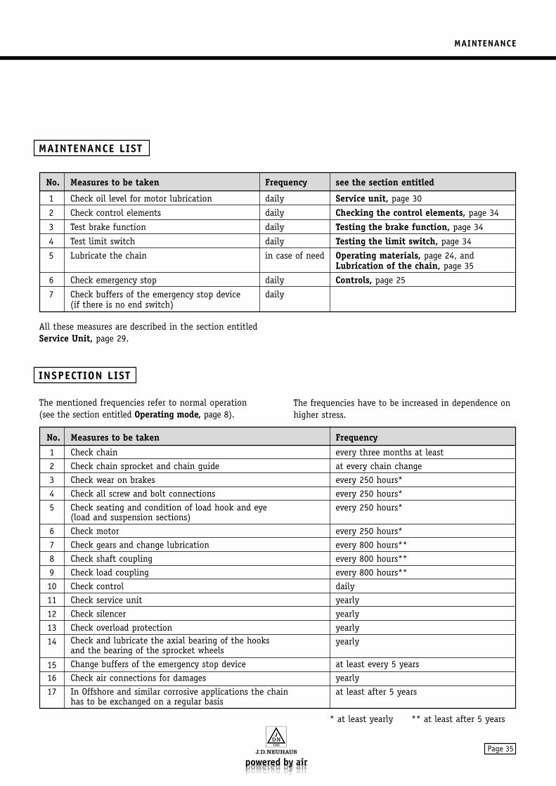
All these measures are described in the section entitledService Unit, page 29.
The mentioned frequencies refer to normal operation (see the section entitled Operating mode, page 8).
The frequencies have to be increased in dependence onhigher stress.
INSPECTION LIST
MAINTENANCE LIST
No. Measures to be taken Frequency see the section entitled
1 Check oil level for motor lubrication daily Service unit, page 30
2 Check control elements daily Checking the control elements, page 34
3 Test brake function daily Testing the brake function, page 34
4 Test limit switch daily Testing the limit switch, page 34
5 Lubricate the chain in case of need Operating materials, page 24, andLubrication of the chain, page 35
6 Check emergency stop daily Controls, page 25
7 Check buffers of the emergency stop device daily(if there is no end switch)
No. Measures to be taken Frequency
1 Check chain every three months at least
2 Check chain sprocket and chain guide at every chain change
3 Check wear on brakes every 250 hours*
4 Check all screw and bolt connections every 250 hours*
5 Check seating and condition of load hook and eye every 250 hours*(load and suspension sections)
6 Check motor every 250 hours*
7 Check gears and change lubrication every 800 hours**
8 Check shaft coupling every 800 hours**
9 Check load coupling every 800 hours**
10 Check control daily
11 Check service unit yearly
12 Check silencer yearly
13 Check overload protection yearly
14 Check and lubricate the axial bearing of the hooks yearlyand the bearing of the sprocket wheels
15 Change buffers of the emergency stop device at least every 5 years
16 Check air connections for damages yearly
17 In Offshore and similar corrosive applications the chain at least after 5 yearshas to be exchanged on a regular basis
* at least yearly ** at least after 5 years
MAINTENANCE
Page 36
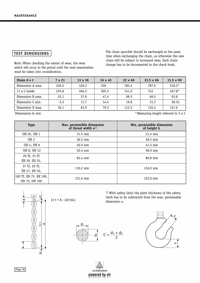
Note: When checking the extent of wear, the wearwhich will occur in the period until the next examinationmust be taken into consideration.
The chain sprocket should be exchanged at the sametime when exchanging the chain, as otherwise the newchain will be subject to increased wear. Each chainchange has to be documented in the check book.
1) With safety latch the plate thickness of the safetylatch has to be subtracted from the max. permissabledimension a.
TEST DIMENSIONS
C = d1 + d2
2
d1
d 2
Chain d x t 7 x 21 13 x 36 16 x 45 22 x 66 23.5 x 66 31.5 x 90
Dimension A max. 249.2 429.2 536 783.4 787.9 518.3*
11 x t inside 235.8 404.3 505.3 741.2 743 457.8*
Dimension B max. 22.1 37.9 47.4 69.5 69.5 93.8
Dimension C min. 6.3 11.7 14.4 19.8 21.2 28.35
Dimension D max. 36.1 63.9 79.3 113.3 116.4 157.6
Type Max. permissible dimension Min. permissible dimensionof throat width a1) of height h
UH 05, UH 1 31.5 mm 21.4 mm
UH 2 36.5 mm 28.5 mm
UH 4, UH 6 46.0 mm 41.3 mm
UH 8, UH 12 50.4 mm 58.9 mm
20 TI, 25 TI 83.4 mm 80.8 mm
EH 20, EH 25,
37 TI, 50 TI, 110.2 mm 116.9 mm
EH 37, EH 50,
100 TI, EH 75, EH 100, 131.0 mm 152.0 mm
UH 75, UH 100
Dimensions in mm *Measuring length referred to 5 x t
ACCESSORIES
Page 37
Use only JDN chain containers with JDN Air Hoists. Other constructions could be a high safety risk.
Never exceed the permitted filling capacity for a chain container.
For chains in containers lubrication is of utmost importance for making full use of the bucket capacity. Rust on chains assist high piling up of the chain in the bucket and is therefore not allowed.
When the chain runs into the container it has to beobserved that between lower edge of mid section andchain pile at least 5 chain links can hang withoutobstruction.
The chain may only pass into the container over thechain drive. Should it have fallen out of the containerfor example during transportation it must be completelyextended at the load hook side and then returned intothe container over the chain drive with running hoist.
In case a load is fastened directly under the load hookit has to be safeguarded that it cannot be drivenagainst the chain container. If necessary a clampingsleeve has to be mounted on the chain above the loadhook acting as an emergency stop at the control lever.
DANGER!When operating JDN Air Hoists without achain container it has to be made certainthat the idle chain running up and down thechain sprocket (unloaded chain end) doesnot cause any risks for example byinterlocking, striking or falling down.
Crash dangers may also arise when duringthe lifting process the idle chain at first settles on large surface loads or other surfaces above the transport level and thenslides or falls down.
DANGER!Do not exceed the admissible filling capacity!Danger of a chain drop!
DANGER!When using a chain container the lubricationof the chain is of special importance to avoidthe chain to fall out.
CAUTION!The chain container must be protectedagainst impacts from the load when lifting. Fit a chain stop to the chain if required.
CAUTION!Do not allow the chain to pile up in the chain container.
CHAIN CONTAINER
ACCESSORIES
ACCESSORIES
Page 38
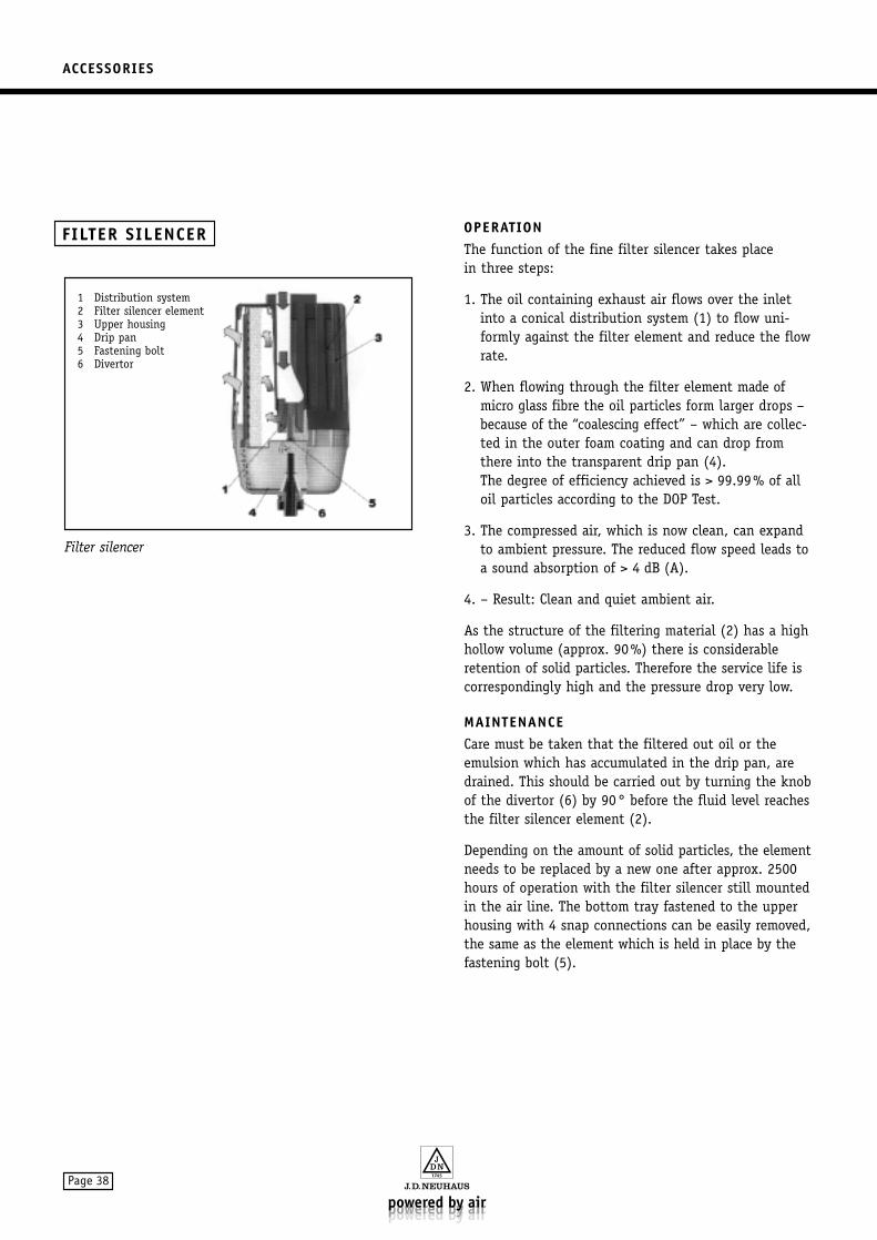
OPERATIONThe function of the fine filter silencer takes place in three steps:
1. The oil containing exhaust air flows over the inletinto a conical distribution system (1) to flow uni-formly against the filter element and reduce the flowrate.
2. When flowing through the filter element made ofmicro glass fibre the oil particles form larger drops –because of the “coalescing effect” – which are collec-ted in the outer foam coating and can drop fromthere into the transparent drip pan (4). The degree of efficiency achieved is > 99.99% of alloil particles according to the DOP Test.
3. The compressed air, which is now clean, can expandto ambient pressure. The reduced flow speed leads toa sound absorption of > 4 dB (A).
4. – Result: Clean and quiet ambient air.
As the structure of the filtering material (2) has a highhollow volume (approx. 90%) there is considerableretention of solid particles. Therefore the service life iscorrespondingly high and the pressure drop very low.
MAINTENANCECare must be taken that the filtered out oil or theemulsion which has accumulated in the drip pan, aredrained. This should be carried out by turning the knobof the divertor (6) by 90° before the fluid level reachesthe filter silencer element (2).
Depending on the amount of solid particles, the elementneeds to be replaced by a new one after approx. 2500hours of operation with the filter silencer still mountedin the air line. The bottom tray fastened to the upperhousing with 4 snap connections can be easily removed,the same as the element which is held in place by thefastening bolt (5).
Filter silencer
FILTER SILENCER
1 Distribution system2 Filter silencer element3 Upper housing4 Drip pan5 Fastening bolt6 Divertor
ACCESSORIES
Page 39
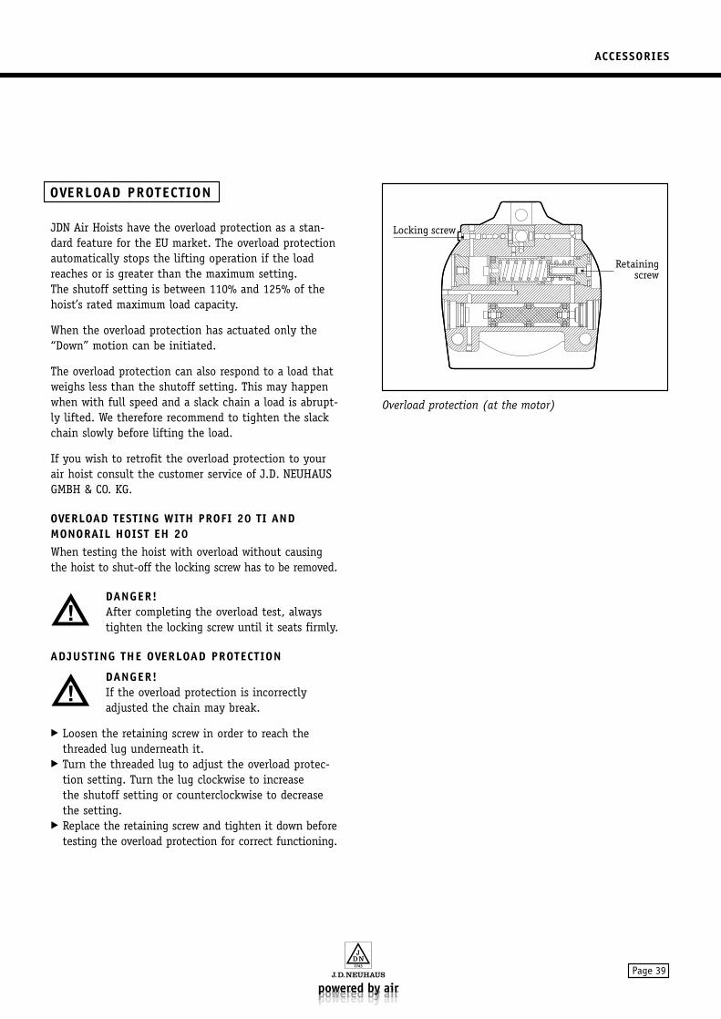
JDN Air Hoists have the overload protection as a stan-dard feature for the EU market. The overload protectionautomatically stops the lifting operation if the load reaches or is greater than the maximum setting. The shutoff setting is between 110% and 125% of thehoist’s rated maximum load capacity.
When the overload protection has actuated only the“Down” motion can be initiated.
The overload protection can also respond to a load thatweighs less than the shutoff setting. This may happenwhen with full speed and a slack chain a load is abrupt-ly lifted. We therefore recommend to tighten the slackchain slowly before lifting the load.
If you wish to retrofit the overload protection to yourair hoist consult the customer service of J.D. NEUHAUSGMBH & CO. KG.
OVERLOAD TESTING WITH PROFI 20 TI ANDMONORAIL HOIST EH 20When testing the hoist with overload without causingthe hoist to shut-off the locking screw has to be removed.
DANGER!After completing the overload test, always tighten the locking screw until it seats firmly.
ADJUSTING THE OVERLOAD PROTECTION
DANGER!If the overload protection is incorrectlyadjusted the chain may break.
Loosen the retaining screw in order to reach thethreaded lug underneath it.
Turn the threaded lug to adjust the overload protec-tion setting. Turn the lug clockwise to increase the shutoff setting or counterclockwise to decreasethe setting.
Replace the retaining screw and tighten it down beforetesting the overload protection for correct functioning.
Overload protection (at the motor)
Q
QQQ
QQQQ
QQQQ
QQQQ
QQQQ
QQQ
Q
¢
¢¢¢
¢¢¢¢
¢¢¢¢
¢¢¢¢
¢¢¢¢
¢¢¢
¢
QQQQQ
¢¢¢¢¢
¢¢
QQ¢¢
¢¢
QQ¢¢
¢¢
QQQQQQ
¢¢¢¢¢¢
QQQQ
QQQQ
QQQ
¢¢
¢¢¢¢
¢¢¢¢
¢¢¢
QQ¢¢
¢¢
QQQ
QQ¢¢¢
¢¢
@@@@
ÀÀÀÀ
@@@@
ÀÀÀÀ
@@@@
ÀÀÀÀ
@@@@
ÀÀÀÀ
@@@@
ÀÀÀÀ
QQQQ
¢¢¢¢
@@@ÀÀÀ@@@ÀÀÀ@@@ÀÀÀ@@@ÀÀÀ@@@ÀÀÀQQQ¢¢¢
@@@ÀÀÀ@@@ÀÀÀ@@@ÀÀÀ@@@ÀÀÀ@@@ÀÀÀQQQ¢¢¢
@@@ÀÀÀ@@@ÀÀÀ@@@ÀÀÀ@@@ÀÀÀ@@@ÀÀÀQQQ¢¢¢
QQQ
QQQQ
QQQQ
¢¢¢
¢¢¢¢
¢¢¢¢
Q
QQQ
QQQQ
QQQQ
QQQQ
QQQQ
QQQ
¢
¢¢¢
¢¢¢¢
¢¢¢¢
¢¢¢¢
¢¢¢¢
¢¢¢
¢¢
Q
Q
QQQ
QQQQ
QQQQ
QQQQ
QQQQ
QQQ¢
¢
¢¢¢
¢¢¢¢
¢¢¢¢
¢¢¢¢
¢¢¢¢
¢¢¢
@@
@@@@
@@@@@
@@@@@
@@@@@
@@@@
@@
ÀÀ
ÀÀÀÀ
ÀÀÀÀÀ
ÀÀÀÀÀ
ÀÀÀÀÀ
ÀÀÀÀ
ÀÀ
@@
@@@@
@@@@@
@@@@@
@@@@@
@@@@
@@
ÀÀ
ÀÀÀÀ
ÀÀÀÀÀ
ÀÀÀÀÀ
ÀÀÀÀÀ
ÀÀÀÀ
ÀÀ
@@
@@@@
@@@@@
@@@@@
@@@@@
@@@@
@@
ÀÀ
ÀÀÀÀ
ÀÀÀÀÀ
ÀÀÀÀÀ
ÀÀÀÀÀ
ÀÀÀÀ
ÀÀ
@@
@@@@
@@@@@
@@@@@
@@@@@
@@@@
@@
ÀÀ
ÀÀÀÀ
ÀÀÀÀÀ
ÀÀÀÀÀ
ÀÀÀÀÀ
ÀÀÀÀ
ÀÀ
@@
@@@@
@@@@@
@@@@@
@@@@@
@@@@
@@
ÀÀ
ÀÀÀÀ
ÀÀÀÀÀ
ÀÀÀÀÀ
ÀÀÀÀÀ
ÀÀÀÀ
ÀÀ
QQQQ
QQQQQ
QQQQQ
QQQQQ
QQQQ
¢¢
¢¢¢¢
¢¢¢¢¢
¢¢¢¢¢
¢¢¢¢¢
¢¢¢¢
¢¢
@@@@
ÀÀÀÀ
@@@@
ÀÀÀÀ
@@@@
ÀÀÀÀ
@@@@
ÀÀÀÀ
@@@@
ÀÀÀÀ
QQQQ
¢¢¢¢
@@@ÀÀÀ@@@ÀÀÀ@@@ÀÀÀ@@@ÀÀÀ@@@ÀÀÀQQQ¢¢¢
@@@@
ÀÀÀÀ
@@@@
ÀÀÀÀ
@@@@
ÀÀÀÀ
@@@@
ÀÀÀÀ
@@@@
ÀÀÀÀ
QQQQ
¢¢¢¢
@@ÀÀ@@ÀÀ@@ÀÀ@@ÀÀ@@ÀÀQQ¢¢
@@@@
ÀÀÀÀ
@@@@
ÀÀÀÀ
@@@@
ÀÀÀÀ
@@@@
ÀÀÀÀ
@@@@
ÀÀÀÀ
QQQQ
¢¢¢¢
@@@ÀÀÀ@@@ÀÀÀ@@@ÀÀÀ@@@ÀÀÀ@@@ÀÀÀQQQ¢¢¢
@@@@
ÀÀÀÀ
@@@@
ÀÀÀÀ
@@@@
ÀÀÀÀ
@@@@
ÀÀÀÀ
@@@@
ÀÀÀÀ
QQQQ
¢¢¢¢
@@@ÀÀÀ@@@ÀÀÀ@@@ÀÀÀ@@@ÀÀÀ@@@ÀÀÀQQQ¢¢¢
@@@@
ÀÀÀÀ
@@@@
ÀÀÀÀ
@@@@
ÀÀÀÀ
@@@@
ÀÀÀÀ
@@@@
ÀÀÀÀ
QQQQ
¢¢¢¢
@@@ÀÀÀ@@@ÀÀÀ@@@ÀÀÀ@@@ÀÀÀ@@@ÀÀÀQQQ¢¢¢
@@@@
ÀÀÀÀ
@@@@
ÀÀÀÀ
@@@@
ÀÀÀÀ
@@@@
ÀÀÀÀ
@@@@
ÀÀÀÀ
QQQQ
¢¢¢¢
@@@ÀÀÀ@@@ÀÀÀ@@@ÀÀÀ@@@ÀÀÀ@@@ÀÀÀQQQ¢¢¢
QQQ
Q¢¢
¢¢¢
¢
OVERLOAD PROTECTION
Locking screw•
•Retaining
screw
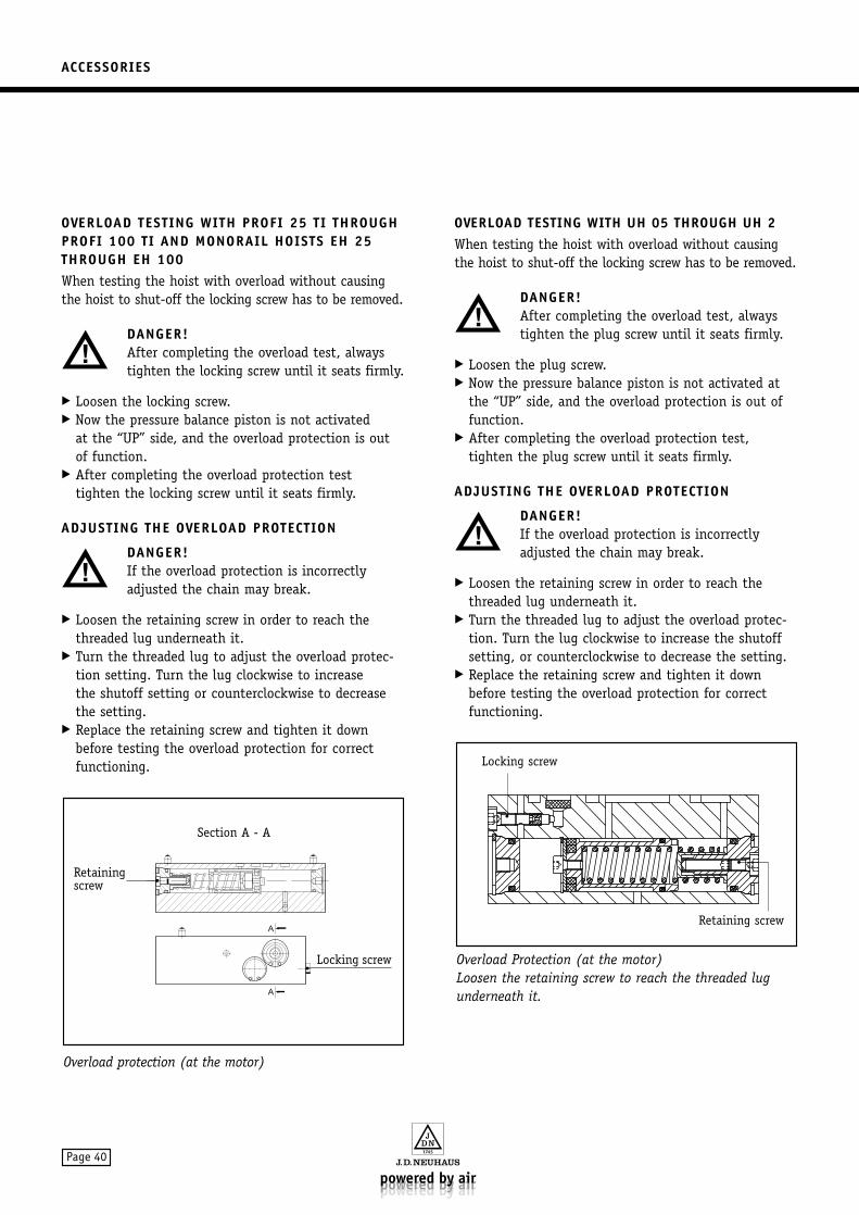
ACCESSORIES
Page 40
OVERLOAD TESTING WITH PROFI 25 TI THROUGHPROFI 100 TI AND MONORAIL HOISTS EH 25THROUGH EH 100When testing the hoist with overload without causingthe hoist to shut-off the locking screw has to be removed.
DANGER!After completing the overload test, always tighten the locking screw until it seats firmly.
Loosen the locking screw. Now the pressure balance piston is not activated
at the “UP” side, and the overload protection is outof function.
After completing the overload protection test tighten the locking screw until it seats firmly.
ADJUSTING THE OVERLOAD PROTECTION
DANGER!If the overload protection is incorrectlyadjusted the chain may break.
Loosen the retaining screw in order to reach thethreaded lug underneath it.
Turn the threaded lug to adjust the overload protec-tion setting. Turn the lug clockwise to increase the shutoff setting or counterclockwise to decreasethe setting.
Replace the retaining screw and tighten it down before testing the overload protection for correct functioning.
OVERLOAD TESTING WITH UH 05 THROUGH UH 2When testing the hoist with overload without causingthe hoist to shut-off the locking screw has to be removed.
DANGER!After completing the overload test, alwaystighten the plug screw until it seats firmly.
Loosen the plug screw. Now the pressure balance piston is not activated at
the “UP” side, and the overload protection is out offunction.
After completing the overload protection test, tighten the plug screw until it seats firmly.
ADJUSTING THE OVERLOAD PROTECTION
DANGER!If the overload protection is incorrectlyadjusted the chain may break.
Loosen the retaining screw in order to reach thethreaded lug underneath it.
Turn the threaded lug to adjust the overload protec-tion. Turn the lug clockwise to increase the shutoffsetting, or counterclockwise to decrease the setting.
Replace the retaining screw and tighten it down before testing the overload protection for correct functioning.
Overload Protection (at the motor)Loosen the retaining screw to reach the threaded lugunderneath it.
Overload protection (at the motor)
.
..
..
.
(( (
.
A
A
. . . .
..
..
. .
.. . . . .
..
..
..
.
Section A - A
Retaining •screw
•Locking screw
Locking screw
Retaining screw
•
•
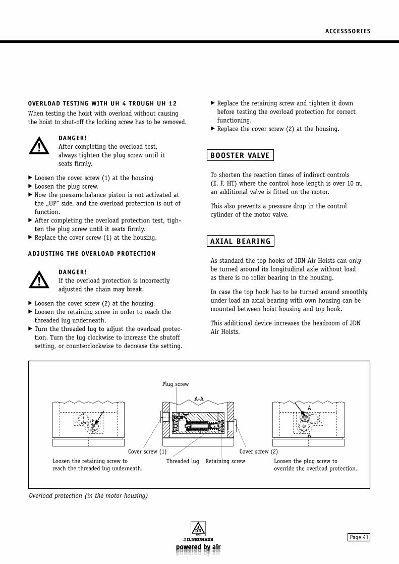
ACCESSSORIES
Page 41
OVERLOAD TESTING WITH UH 4 TROUGH UH 12When testing the hoist with overload without causingthe hoist to shut-off the locking screw has to be removed.
DANGER!After completing the overload test,always tighten the plug screw until itseats firmly.
Loosen the cover screw (1) at the housing Loosen the plug screw. Now the pressure balance piston is not activated at
the „UP“ side, and the overload protection is out offunction.
After completing the overload protection test, tigh-ten the plug screw until it seats firmly.
Replace the cover screw (1) at the housing.
ADJUSTING THE OVERLOAD PROTECTION
DANGER!If the overload protection is incorrectlyadjusted the chain may break.
Loosen the cover screw (2) at the housing. Loosen the retaining screw in order to reach the
threaded lug underneath. Turn the threaded lug to adjust the overload protec-
tion. Turn the lug clockwise to increase the shutoffsetting, or counterclockwise to decrease the setting.
Replace the retaining screw and tighten it down before testing the overload protection for correct functioning.
Replace the cover screw (2) at the housing.
To shorten the reaction times of indirect controls(E, F, HT) where the control hose length is over 10 m,an additional valve is fitted on the motor.
This also prevents a pressure drop in the control cylinder of the motor valve.
As standard the top hooks of JDN Air Hoists can only be turned around its longitudinal axle without load as there is no roller bearing in the housing.
In case the top hook has to be turned around smoothlyunder load an axial bearing with own housing can bemounted between hoist housing and top hook.
This additional device increases the headroom of JDNAir Hoists.
AXIAL BEARING
BOOSTER VALVE
Overload protection (in the motor housing)
Loosen the plug screw tooverride the overload protection.
Loosen the retaining screw toreach the threaded lug underneath.
•
Threaded lug Retaining screw
• •
Cover screw (2)
•
Plug screw
A-A
Cover screw (1)
•
A
A
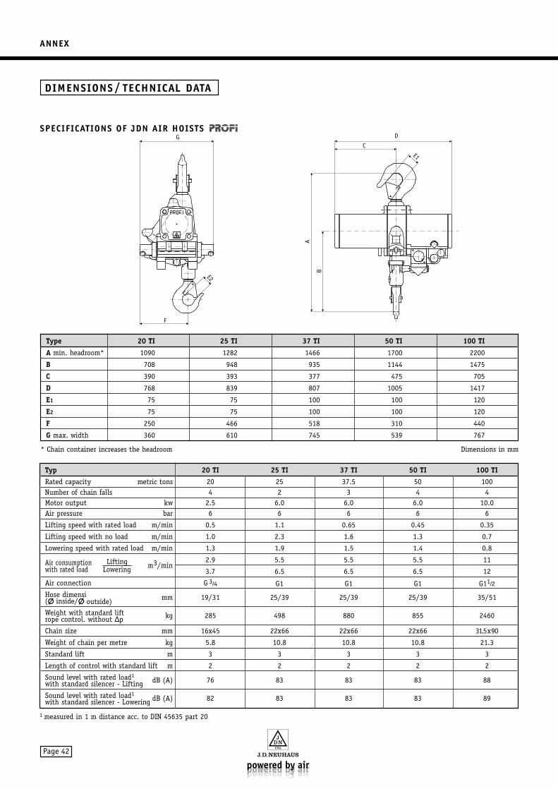
ANNEX
Page 42
Type 20 TI 25 TI 37 TI 50 TI 100 TI
A min. headroom* 1090 1282 1466 1700 2200
B 708 948 935 1144 1475
C 390 393 377 475 705
D 768 839 807 1005 1417
E1 75 75 100 100 120
E2 75 75 100 100 120
F 250 466 518 310 440
G max. width 360 610 745 539 767
Dimensions in mm* Chain container increases the headroom
G
E2
F
C
A
B
D
E1
SPECIFICATIONS OF JDN AIR HOISTS
DIMENSIONS / TECHNICAL DATA
Typ 20 TI 25 TI 37 TI 50 TI 100 TI
Rated capacity metric tons 20 25 37.5 50 100Number of chain falls 4 2 3 4 4Motor output kw 2.5 6.0 6.0 6.0 10.0Air pressure bar 6 6 6 6 6
Lifting speed with rated load m/min 0.5 1.1 0.65 0.45 0.35
Lifting speed with no load m/min 1.0 2.3 1.6 1.3 0.7
Lowering speed with rated load m/min 1.3 1.9 1.5 1.4 0.8
Air consumption Lifting m3/min2.9 5.5 5.5 5.5 11
with rated load Lowering 3.7 6.5 6.5 6.5 12
Air connection G 3⁄4 G1 G1 G1 G11⁄2
Hose dimensi( inside/ outside) mm 19/31 25/39 25/39 25/39 35/51
Weight with standard liftrope control. without ∆p kg 285 498 880 855 2460
Chain size mm 16x45 22x66 22x66 22x66 31.5x90
Weight of chain per metre kg 5.8 10.8 10.8 10.8 21.3
Standard lift m 3 3 3 3 3
Length of control with standard lift m 2 2 2 2 2
Sound level with rated load1
with standard silencer - Lifting dB (A) 76 83 83 83 88
Sound level with rated load1
with standard silencer - Lowering dB (A) 82 83 83 83 89
1 measured in 1 m distance acc. to DIN 45635 part 20
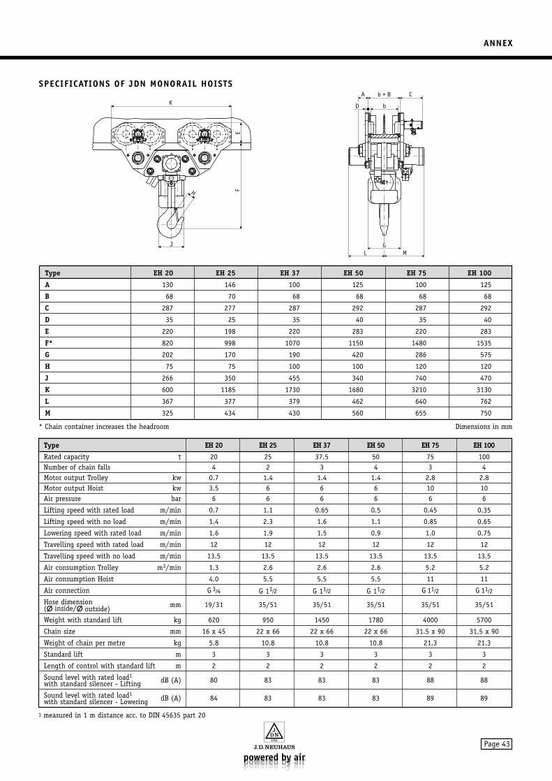
ANNEX
Page 43
SPECIFICATIONS OF JDN MONORAIL HOISTS
Type EH 20 EH 25 EH 37 EH 50 EH 75 EH 100
Rated capacity t 20 25 37.5 50 75 100Number of chain falls 4 2 3 4 3 4Motor output Trolley kw 0.7 1.4 1.4 1.4 2.8 2.8Motor output Hoist kw 3.5 6 6 6 10 10Air pressure bar 6 6 6 6 6 6
Lifting speed with rated load m/min 0.7 1.1 0.65 0.5 0.45 0.35
Lifting speed with no load m/min 1.4 2.3 1.6 1.1 0.85 0.65
Lowering speed with rated load m/min 1.6 1.9 1.5 0.9 1.0 0.75
Travelling speed with rated load m/min 12 12 12 12 12 12
Travelling speed with no load m/min 13.5 13.5 13.5 13.5 13.5 13.5
Air consumption Trolley m3/min 1.3 2.6 2.6 2.6 5.2 5.2
Air consumption Hoist 4.0 5.5 5.5 5.5 11 11
Air connection G 3⁄4 G 11⁄2 G 11⁄2 G 11⁄2 G 11⁄2 G 11⁄2
Hose dimension ( inside/ outside) mm 19/31 35/51 35/51 35/51 35/51 35/51
Weight with standard lift kg 620 950 1450 1780 4000 5700
Chain size mm 16 x 45 22 x 66 22 x 66 22 x 66 31.5 x 90 31.5 x 90
Weight of chain per metre kg 5.8 10.8 10.8 10.8 21.3 21.3
Standard lift m 3 3 3 3 3 3
Length of control with standard lift m 2 2 2 2 2 2
Sound level with rated load1
with standard silencer - Lifting dB (A) 80 83 83 83 88 88
Sound level with rated load1
with standard silencer - Lowering dB (A) 84 83 83 83 89 89
1 measured in 1 m distance acc. to DIN 45635 part 20
Type EH 20 EH 25 EH 37 EH 50 EH 75 EH 100
A 130 146 100 125 100 125
B 68 70 68 68 68 68
C 287 277 287 292 287 292
D 35 25 35 40 35 40
E 220 198 220 283 220 283
F* 820 998 1070 1150 1480 1535
G 202 170 190 420 286 575
H 75 75 100 100 120 120
J 266 350 455 340 740 470
K 600 1185 1730 1680 3210 3130
L 367 377 379 462 640 762
M 325 434 430 560 655 750
Dimensions in mm
K
J
H FE
G
A C
b
b + B
D
L M
* Chain container increases the headroom
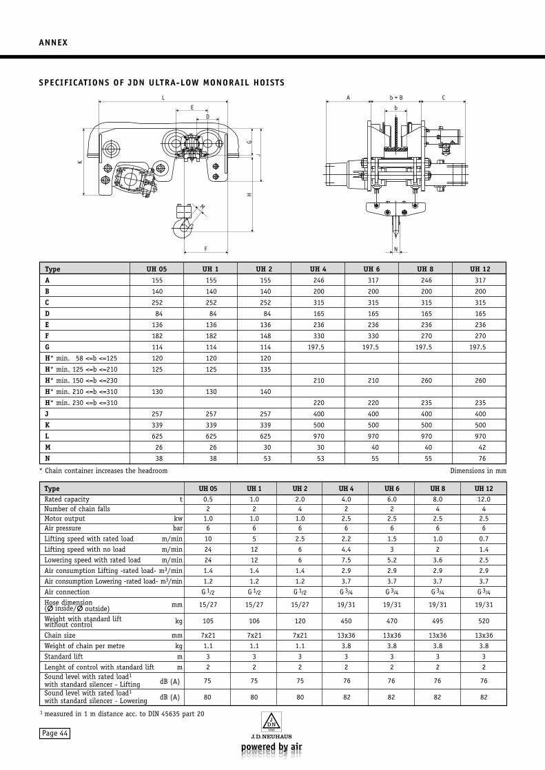
ANNEX
Page 44
SPECIFICATIONS OF JDN ULTRA-LOW MONORAIL HOISTS
Type UH 05 UH 1 UH 2 UH 4 UH 6 UH 8 UH 12Rated capacity t 0.5 1.0 2.0 4.0 6.0 8.0 12.0Number of chain falls 2 2 4 2 2 4 4Motor output kw 1.0 1.0 1.0 2.5 2.5 2.5 2.5Air pressure bar 6 6 6 6 6 6 6Lifting speed with rated load m/min 10 5 2.5 2.2 1.5 1.0 0.7Lifting speed with no load m/min 24 12 6 4.4 3 2 1.4Lowering speed with rated load m/min 24 12 6 7.5 5.2 3.6 2.5Air consumption Lifting -rated load- m3/min 1.4 1.4 1.4 2.9 2.9 2.9 2.9Air consumption Lowering -rated load- m3/min 1.2 1.2 1.2 3.7 3.7 3.7 3.7Air connection G 1⁄2 G 1⁄2 G 1⁄2 G 3⁄4 G 3⁄4 G 3⁄4 G 3⁄4
Hose dimension ( inside/ outside) mm 15/27 15/27 15/27 19/31 19/31 19/31 19/31
Weight with standard lift without control kg 105 106 120 450 470 495 520
Chain size mm 7x21 7x21 7x21 13x36 13x36 13x36 13x36Weight of chain per metre kg 1.1 1.1 1.1 3.8 3.8 3.8 3.8Standard lift m 3 3 3 3 3 3 3Lenght of control with standard lift m 2 2 2 2 2 2 2Sound level with rated load1
dB (A)with standard silencer - Lifting 75 75 75 76 76 76 76
Sound level with rated load1
with standard silencer - Lowering dB (A) 80 80 80 82 82 82 82
Type UH 05 UH 1 UH 2 UH 4 UH 6 UH 8 UH 12A 155 155 155 246 317 246 317
B 140 140 140 200 200 200 200
C 252 252 252 315 315 315 315
D 84 84 84 165 165 165 165
E 136 136 136 236 236 236 236
F 182 182 148 330 330 270 270
G 114 114 114 197.5 197.5 197.5 197.5
H* min. 58 <=b <=125 120 120 120
H* min. 125 <=b <=210 125 125 135
H* min. 150 <=b <=230 210 210 260 260
H* min. 210 <=b <=310 130 130 140
H* min. 230 <=b <=310 220 220 235 235
J 257 257 257 400 400 400 400
K 339 339 339 500 500 500 500
L 625 625 625 970 970 970 970
M 26 26 30 30 40 40 42
N 38 38 53 53 55 55 76
Dimensions in mm
L
E
F
D
G
K
H
M
A b + B
b
N
C
* Chain container increases the headroom
1 measured in 1 m distance acc. to DIN 45635 part 20

NOTES
Page 45

is a registered trademark of our company.BA 811 GB · Issue: March 2004 · Alterations reserved · With the issueof this edition all previous versions are null and void · 32004
J.D. Neuhaus GmbH & Co.KG_D-58449 Witten-HevenPhone: +49(0)2302-208-0_Fax: +49(0)2302-208-286 Web site: www.jdn.de_E-mail: [email protected]