Embed Size (px)
Citation preview

26.08.2013 Wachendorff Elektronik GmbH & Co. KG Industriestraße 7 DE-65366 Geisenheim
Wachendorff Elektronik GmbH & Co. KG
Technical Data Sheet OPUS A3 ECO Full
TDS OPUS A3eF, 26.08.2013
OPUS A3 Eco Full Landscape
OPUS A3 Eco Full Portrait

26.08.2013 Wachendorff Elektronik GmbH & Co. KG Industriestraße 7 DE-65366 Geisenheim
Wachendorff Elektronik GmbH & Co. KG
1 Order Numbers OPUS A3 ECO Full
Wachendorff Projektor
Landscape OPUSA3EL1CANF000
Portrait OPUSA3EP1CANF000
CodeSys
Landscape OPUSA3EL1CDSF000
Portrait OPUSA3EP1CDSF000
ISO-VT
Landscape OPUSA3EL1ISOF000
2 Mechanical
2.1 Dimensions
26.08.2013 Wachendorff Elektronik GmbH & Co. KG Industriestraße 7 DE-65366 Geisenheim
Wachendorff Elektronik GmbH & Co. KG
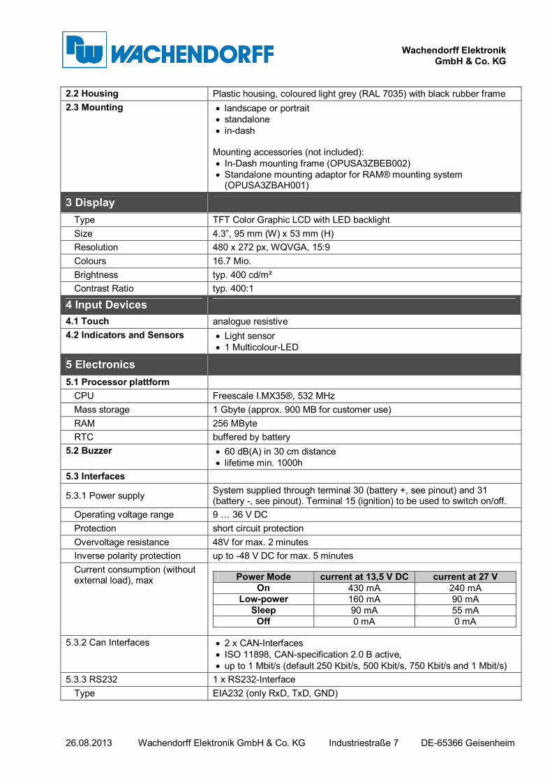
2.2 Housing Plastic housing, coloured light grey (RAL 7035) with black rubber frame
2.3 Mounting • landscape or portrait
• standalone
• in-dash Mounting accessories (not included):
• In-Dash mounting frame (OPUSA3ZBEB002)
• Standalone mounting adaptor for RAM® mounting system (OPUSA3ZBAH001)
3 Display
Type TFT Color Graphic LCD with LED backlight
Size 4.3”, 95 mm (W) x 53 mm (H)
Resolution 480 x 272 px, WQVGA, 15:9
Colours 16.7 Mio.
Brightness typ. 400 cd/m²
Contrast Ratio typ. 400:1
4 Input Devices
4.1 Touch analogue resistive
4.2 Indicators and Sensors • Light sensor
• 1 Multicolour-LED
5 Electronics
5.1 Processor plattform
CPU Freescale I.MX35®, 532 MHz
Mass storage 1 Gbyte (approx. 900 MB for customer use)
RAM 256 MByte
RTC buffered by battery
5.2 Buzzer • 60 dB(A) in 30 cm distance
• lifetime min. 1000h
5.3 Interfaces
5.3.1 Power supply System supplied through terminal 30 (battery +, see pinout) and 31 (battery -, see pinout). Terminal 15 (ignition) to be used to switch on/off.
Operating voltage range 9 … 36 V DC
Protection short circuit protection
Overvoltage resistance 48V for max. 2 minutes
Inverse polarity protection up to -48 V DC for max. 5 minutes
Current consumption (without external load), max Power Mode current at 13,5 V DC current at 27 V
On 430 mA 240 mA Low-power 160 mA 90 mA
Sleep 90 mA 55 mA Off 0 mA 0 mA
5.3.2 Can Interfaces • 2 x CAN-Interfaces
• ISO 11898, CAN-specification 2.0 B active,
• up to 1 Mbit/s (default 250 Kbit/s, 500 Kbit/s, 750 Kbit/s and 1 Mbit/s)
5.3.3 RS232 1 x RS232-Interface
Type EIA232 (only RxD, TxD, GND)

26.08.2013 Wachendorff Elektronik GmbH & Co. KG Industriestraße 7 DE-65366 Geisenheim
Wachendorff Elektronik GmbH & Co. KG
Speed max. 115 Kbps
5.3.4 USB Host 2.0
Main connector 1 x Full speed
5.3.5 Inputs 4 configurable analogue/digital inputs
input impedance > 3kOhm
resolution 10 bit resolution (1028 digits, 1 digit = 11,7 mV)
Voltage range 0 … 12 V
max. protectable input voltage 36 V DC
protection short circuit protection
frequency max. signal frequency 50 Hz
5.3.6 Outputs 3 digital outputs
short circuit protection up to 36 V DC
Imax 300 mA open drain
RDS,on < 1 Ohm
RDS,off > 100 kOhm
5.3.7 Video-Interface analog video input, 1 Vss
5.3.8 Ehthernet-Interface 1 x 10/100 Mbit/s Base T
6 Connections
Main connector Tyco-AMP 1437288-6
• Mating connector (customer) Tyco-AMP 3-1437290-7
• Mating crimp contact (customer) Tyco AMP 3-1447221-4
Video connector M12 round connector, female, 5-pole, B-coded acc. to EN 61076-2-101
Ethernet connector M12 round connector, female, 4-pole, D-coded acc. to EN 61076-2-101
Connector pinout see chap. 9.
7 Software
7.1 Operating System Linux, kernel 2.6.28
7.2 Application Programming • Wachendorff Projektor Tool
• Optional: Codesys-Tools (3.5)
• Optional: ISO-VT (Q4/2012)
• Optional: C/C++
8 Testing and Verification
8.1 CE-Compliance EU Directive 2004/108/EC (EMC) according to
• EN 12895: Industrial Trucks – Electromagnetic compatibility
• EN 13309: Construction machinery – Electromagnetic compatibility of machines with internal electrical power supply
• EN ISO 14982: Agricultural and forestry machinery - Electromagnetic compatibility - Test methods and acceptance criteria
8.2 8.2 E1 - Type approval EU Directive ECE R10.4
8.3 Protection Level (IP Code) IP 6k5 and 6k7 according to ISO 20653: Road Vehicles – Degrees of protection (IP-Code) – Protection of electrical equipment against foreign objects, water and access
8.4 Electrical 12 and 24V-Systems according to:
• ISO 16750-2: Road Vehicles – Environmental conditions and testing for electrical and electronic equipment – Electrical loads
• ISO 15003: Agricultural Engineering – Electrical and electronic equipment – Testing resistance to environmental conditions

26.08.2013 Wachendorff Elektronik GmbH & Co. KG Industriestraße 7 DE-65366 Geisenheim
Wachendorff Elektronik GmbH & Co. KG
8.5 Mechanical • According to ISO 16750-3: Road Vehicles – Environmental conditions and testing for electrical and electronic equipment – Mechanical loads, Code L
• ISO 15003: Agricultural Engineering – Electrical and electronic equipment – Testing resistance to environmental conditions o Mechanical Shock: Level 2 o Random Vibration: Level 2 o Sinusoidal Vibration: Level 2
8.6 Climate • According to ISO 16750-4: Road Vehicles – Environmental conditions and testing for electrical and electronic equipment – Climatic Loads o Operating Temperature Range: -30 … +65°C o Storage Temperature Range: -40 … +85°C
• ISO 15003: Agricultural Engineering – Electrical and electronic equipment – Testing resistance to environmental conditions
9 Pinout
9.1 Mainconnector pinout pin no. assignment description
1 VCC supply voltage +; terminal 30
2 Ignition Input ignition input; terminal 15
3 GND supply voltage - ;terminal 31
4 CarGND Car GND
5 n. c. Not connected
6 n. c. Not connected
7 n. c. Not connected
8 CAN1H CAN 1 high
9 CAN1L CAN 1 low
10 CAN2H CAN 2 high
11 CAN2L CAN 2 low
12 USB_VCC USB +5V supply
13 USB_GND USB supply GND
14 USB_D- USB Data -
15 USB_D+ USB Data +
16 RS232: RxD RS232 receive data
17 RS232: TxD RS232 transmit data
18 RS232: GND RS232 GND
19 A/DI3 analog/digital input 3
20 A/DI1 analog/digital input 1
21 A/DI2 analog/digital input 2
22 A/DI4 analog/digital input 4
23 SERV_EN service enable
24 DO3 digital output 3
25 DO1 digital output 1
26 DO2 digital output2

26.08.2013 Wachendorff Elektronik GmbH & Co. KG Industriestraße 7 DE-65366 Geisenheim
Wachendorff Elektronik GmbH & Co. KG
view on rear side of the A3
9.2 Videoconnector pinout
Round Connector, 5 pins, M12
1 VidSig+
2 n. c.
3 Camera+
4 Camera -
5 VidSig GND
Video- Connector, M12, female, 5 pins, b-coded
view on rear side of the A3
9.3 Ethernetconnector pinout
Round Connector, 4 pins, M12, acc. To IEC 61076-2-101
1 TD+
2 RD+
3 TD-
4 RD-
Ethernet Connector, M12, female, 4 pins, d-coded
view on rear side of the A3