Embed Size (px)
Citation preview
Technical Data 50/60 HzVertical multi-stage centrifugal pumps
serie: DPV 85
20071138
2
Table of Contents
1 Pump introduction1.1 Model key............................................................................................................................................... 31.2 Description of the product ...................................................................................................................... 31.3 Basic material variants........................................................................................................................... 31.4 Pump bearing......................................................................................................................................... 31.5 Working range........................................................................................................................................ 31.6 Motor...................................................................................................................................................... 41.7 Mechanical shaft seal ............................................................................................................................ 51.8 Modular built-up ..................................................................................................................................... 51.9 Approvals ............................................................................................................................................... 51.10 Operation ............................................................................................................................................... 61.11 Measuring, draining and venting............................................................................................................ 61.12 Standard construction ............................................................................................................................ 71.13 Parts overview ....................................................................................................................................... 8
2 Performance characteristics2.1 Performance curve details ....................................................................................................................112.2 Performance with variable frequency drive.......................................................................................... 122.3 Performance using other brand of motors ........................................................................................... 122.4 Divergent speed calculation................................................................................................................. 122.5 How to read the values from the curves .............................................................................................. 13
3 Technical specifications3.1 DPV(C/S)F 85 50 Hz, with 2 pole motor ~2900 rpm EFF 2 ................................................................. 143.2 DPV(C/S)F 85 50 Hz, with 4 pole motor ~1450 rpm EFF 2 ................................................................. 163.3 DPV(C/S)F 85 60 Hz, with 2 pole motor ~3500 rpm EFF 2 ................................................................. 183.4 DPV(C/S)F 85 60 Hz, with 4 pole motor ~1750 rpm EFF 2 ................................................................. 203.5 DPV(C/S)F 85 50 Hz, 2 pole without motor @ 2900 rpm (IEC) ........................................................... 223.6 DPV(C/S)F 85 50 Hz, 4 pole without motor @ 1450 rpm (IEC) ........................................................... 243.7 DPV(C/S)F 85 60 Hz, 2 pole without motor @ 3500 rpm (IEC) ........................................................... 263.8 DPV(C/S)F 85 60 Hz, 4 pole without motor @ 1750 rpm (IEC) ........................................................... 283.9 Sealing ................................................................................................................................................. 303.10 Connection........................................................................................................................................... 333.11 Motor options ....................................................................................................................................... 34
4 Article numbers4.1 DPVCF 85 50 Hz 2900 rpm ................................................................................................................. 354.2 DPVF 85 50 Hz 2900 rpm.................................................................................................................... 364.3 DPVSF 85 50 Hz 2900 rpm ................................................................................................................. 374.4 DPVCF 85 60 Hz 3500 rpm ................................................................................................................. 384.5 DPVF 85 60 Hz 3500 rpm.................................................................................................................... 394.6 DPVSF 85 60 Hz 3500 rpm ................................................................................................................. 40
5 Chemical resistance5.1 Chemical resistance............................................................................................................................. 41
3
1 Pump introduction
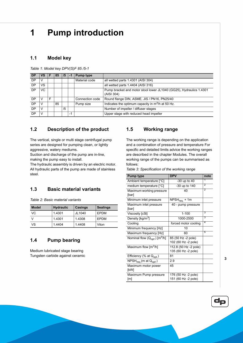
1.1 Model key
Table 1: Model key DPV(S)F 85 /5-1
1.2 Description of the product
The vertical, single or multi stage centrifugal pump series are designed for pumping clean, or lightly aggressive, watery mediums.Suction and discharge of the pump are in-line, making the pump easy to install. The hydraulic assembly is driven by an electric motor. All hydraulic parts of the pump are made of stainless steel.
1.3 Basic material variants
Table 2: Basic material variants
1.4 Pump bearing
Medium lubricated stage bearingTungsten carbide against ceramic
1.5 Working range
The working range is depending on the application and a combination of pressure and temperature For specific and detailed limits advice the working ranges are described in the chapter Modules. The overall working range of the pumps can be summarised as follows:Table 3: Specification of the working range
DP VS F 85 /5 -1 Pump typeDP V Material code all wetted parts 1.4301 (AISI 304) DP VS all wetted parts 1.4404 (AISI 316)DP VC Pump bracket and motor stool lower JL1040 (GG25), Hydraulics 1.4301
(AISI 304)DP V F Connection code Round flange DIN, ASME, JIS / PN16, PN25/40 DP V 85 Pump size Indicates the optimum capacity in m3/h at 50 Hz.DP V /5 Number of impeller / diffuser stagesDP V -1 Upper stage with reduced head impeller
Model Hydraulic Casings Sealings
VC 1.4301 JL1040 EPDM
V 1.4301 1.4308 EPDM
VS 1.4404 1.4408 Viton
Pump type DPV noteAmbient temperature [°C] -30 up to 40 1
medium temperature [°C] -30 up to 140 2
Maximum working pressure [bar]
40 2
Minimum inlet pressure NPSHreq. + 1mMaximum inlet pressure [bar]
40 - pump pressure
Viscosity [cSt] 1-100 3
Density [kg/m3] 1000-2500 3
Cooling forced motor cooling 4
Minimum frequency [Hz] 10Maximum frequency [Hz] 60 5
Nominal flow (Qopt.) [m3/h] 85 (50 Hz -2 pole)102 (60 Hz -2 pole)
Maximum flow [m3/h] 112.8 (50 Hz -2 pole)135 (60 Hz -2 pole)
Efficiency (% at Qopt.) 81NPSHreq.(m at Qopt.) 2.9Maximum motor power [kW]
45
Maximum Pump pressure [m]
176 (50 Hz -2 pole) 151 (60 Hz -2 pole)
4
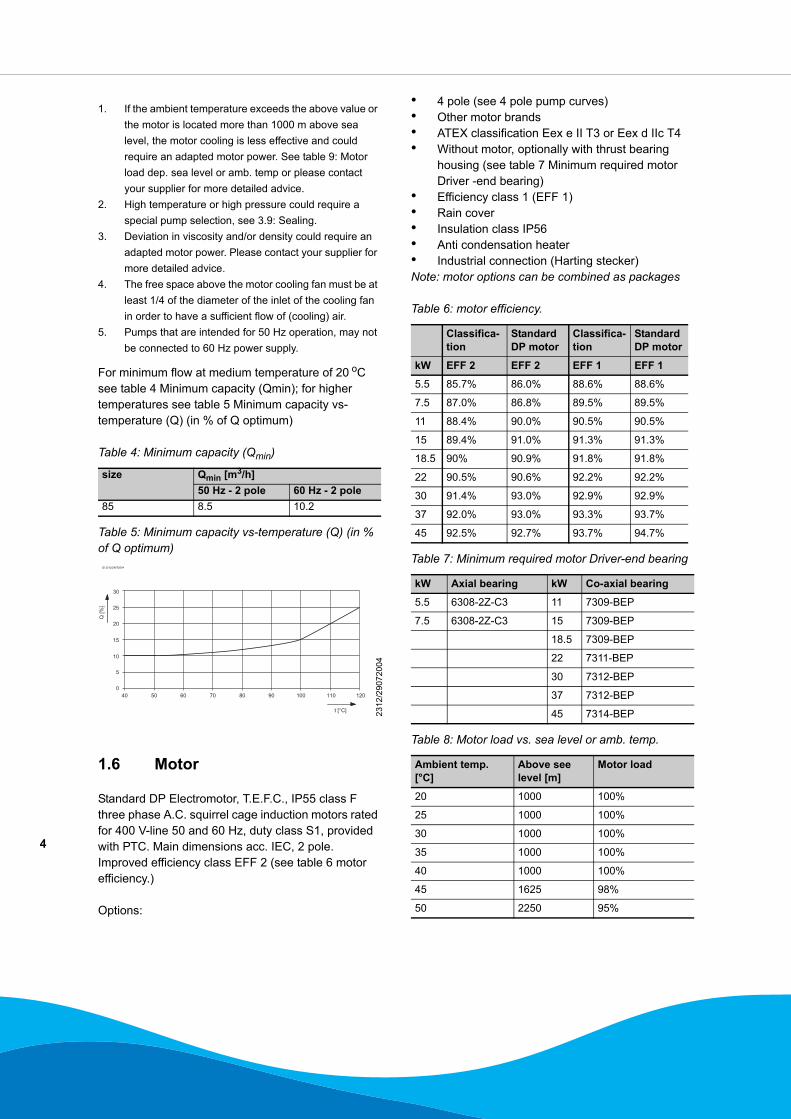
For minimum flow at medium temperature of 20 oC see table 4 Minimum capacity (Qmin); for higher temperatures see table 5 Minimum capacity vs-temperature (Q) (in % of Q optimum)
Table 4: Minimum capacity (Qmin)
Table 5: Minimum capacity vs-temperature (Q) (in % of Q optimum)
1.6 Motor
Standard DP Electromotor, T.E.F.C., IP55 class Fthree phase A.C. squirrel cage induction motors rated for 400 V-line 50 and 60 Hz, duty class S1, provided with PTC. Main dimensions acc. IEC, 2 pole.Improved efficiency class EFF 2 (see table 6 motor efficiency.)
Options:
• 4 pole (see 4 pole pump curves)• Other motor brands• ATEX classification Eex e II T3 or Eex d IIc T4• Without motor, optionally with thrust bearing
housing (see table 7 Minimum required motor Driver -end bearing)
• Efficiency class 1 (EFF 1)• Rain cover• Insulation class IP56• Anti condensation heater• Industrial connection (Harting stecker)Note: motor options can be combined as packages
Table 6: motor efficiency.
Table 7: Minimum required motor Driver-end bearing
Table 8: Motor load vs. sea level or amb. temp.
1. If the ambient temperature exceeds the above value or the motor is located more than 1000 m above sea level, the motor cooling is less effective and could require an adapted motor power. See table 9: Motor load dep. sea level or amb. temp or please contact your supplier for more detailed advice.
2. High temperature or high pressure could require a special pump selection, see 3.9: Sealing.
3. Deviation in viscosity and/or density could require an adapted motor power. Please contact your supplier for more detailed advice.
4. The free space above the motor cooling fan must be at least 1/4 of the diameter of the inlet of the cooling fan in order to have a sufficient flow of (cooling) air.
5. Pumps that are intended for 50 Hz operation, may not be connected to 60 Hz power supply.
size Qmin [m3/h]50 Hz - 2 pole 60 Hz - 2 pole
85 8.5 10.2
ID 2312/29072004
231
2/29
0720
04
40 50 60 70 80 90 100 110 120
0
10
5
15
20
25
30
t [°C]
Q [%
]
Classifica-tion
Standard DP motor
Classifica-tion
Standard DP motor
kW EFF 2 EFF 2 EFF 1 EFF 1
5.5 85.7% 86.0% 88.6% 88.6%
7.5 87.0% 86.8% 89.5% 89.5%
11 88.4% 90.0% 90.5% 90.5%
15 89.4% 91.0% 91.3% 91.3%
18.5 90% 90.9% 91.8% 91.8%
22 90.5% 90.6% 92.2% 92.2%
30 91.4% 93.0% 92.9% 92.9%
37 92.0% 93.0% 93.3% 93.7%
45 92.5% 92.7% 93.7% 94.7%
kW Axial bearing kW Co-axial bearing
5.5 6308-2Z-C3 11 7309-BEP
7.5 6308-2Z-C3 15 7309-BEP
18.5 7309-BEP
22 7311-BEP
30 7312-BEP
37 7312-BEP
45 7314-BEP
Ambient temp. [°C]
Above see level [m]
Motor load
20 1000 100%
25 1000 100%
30 1000 100%
35 1000 100%
40 1000 100%
45 1625 98%
50 2250 95%
5
Table 9: Motor load dep. sea level or amb. temp.
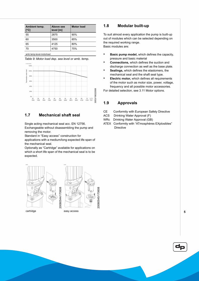
1.7 Mechanical shaft seal
Single acting mechanical seal acc. EN 12756. Exchangeable without disassembling the pump and removing the motor.Standard in “Easy access” construction for applications with a medium/long expected life span of the mechanical seal.Optionally as “Cartridge” available for applications on which a short life span of the mechanical seal is to be expected.
1.8 Modular built-up
To suit almost every application the pump is built-up out of modules which can be selected depending on the required working range.Basic modules are:
• Basic pump model, which defines the capacity, pressure and basic material
• Connections, which defines the suction and discharge connection as well as the base plate.
• Sealings, which defines the elastomers, the mechanical seal and the shaft seal type.
• Electric motor, which defines all requirements of the motor such as motor size, power, voltage, frequency and all possible motor accessories.
For detailed selection, see 3.11 Motor options.
1.9 Approvals
CE Conformity with European Safety DirectiveACS Drinking Water Approval (F)WRc Drinking Water Approval (GB)ATEX Conformity with “ATmosphères EXplosibles” Directive
55 2875 90%
60 3500 85%
65 4125 80%
70 4750 75%
amb temp-level-motorload
ID 3053/19022008
305
3/19
0220
08
ID3028
2008
0544
/170
608
ID3029
2008
0545
/170
608
cartridge easy access
Ambient temp. [°C]
Above see level [m]
Motor load
6
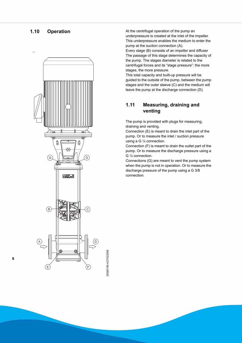
1.10 Operation At the centrifugal operation of the pump an underpressure is created at the inlet of the impeller. This underpressure enables the medium to enter the pump at the suction connection (A).Every stage (B) consists of an impeller and diffuser The passage of this stage determines the capacity of the pump. The stages diameter is related to the centrifugal forces and its “stage pressure”: the more stages, the more pressure.This total capacity and built-up pressure will be guided to the outside of the pump, between the pump stages and the outer sleeve (C) and the medium will leave the pump at the discharge connection (D).
1.11 Measuring, draining and venting
The pump is provided with plugs for measuring, draining and venting.Connection (E) is meant to drain the inlet part of the pump. Or to measure the inlet / suction pressure using a G ¼ connection.Connection (F) is meant to drain the outlet part of the pump. Or to measure the discharge pressure using a G ¼ connection.Connections (G) are meant to vent the pump system when the pump is not in operation. Or to measure the discharge pressure of the pump using a G 3/8 connection.
ID3027
2008
0190
-A/2
7022
008
DA
E F
GG
B C
7
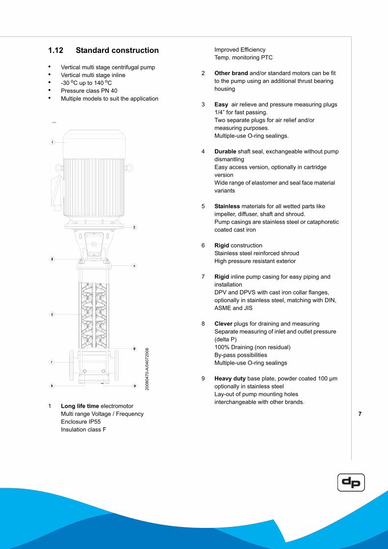
1.12 Standard construction
• Vertical multi stage centrifugal pump• Vertical multi stage inline• -30 oC up to 140 oC• Pressure class PN 40• Multiple models to suit the application
1 Long life time electromotorMulti range Voltage / FrequencyEnclosure IP55Insulation class F
Improved EfficiencyTemp. monitoring PTC
2 Other brand and/or standard motors can be fit to the pump using an additional thrust bearing housing
3 Easy air relieve and pressure measuring plugs 1/4” for fast passing.Two separate plugs for air relief and/or measuring purposes.Multiple-use O-ring sealings.
4 Durable shaft seal, exchangeable without pump dismantlingEasy access version, optionally in cartridge versionWide range of elastomer and seal face material variants
5 Stainless materials for all wetted parts like impeller, diffuser, shaft and shroud.Pump casings are stainless steel or cataphoretic coated cast iron
6 Rigid constructionStainless steel reinforced shroudHigh pressure resistant exterior
7 Rigid inline pump casing for easy piping and installationDPV and DPVS with cast iron collar flanges, optionally in stainless steel, matching with DIN, ASME and JIS
8 Clever plugs for draining and measuringSeparate measuring of inlet and outlet pressure (delta P)100% Draining (non residual)By-pass possibilitiesMultiple-use O-ring sealings
9 Heavy duty base plate, powder coated 100 µmoptionally in stainless steelLay-out of pump mounting holes interchangeable with other brands.
ID3226
2008
0470
-A/0
4072
008
8
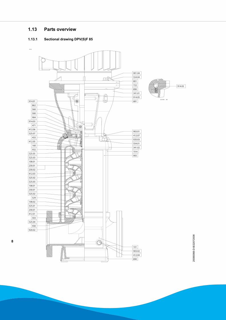
1.13 Parts overview
1.13.1 Sectional drawing DPV(S)F 85
ID3239
2008
0066
-D-B
/220
7200
8
9
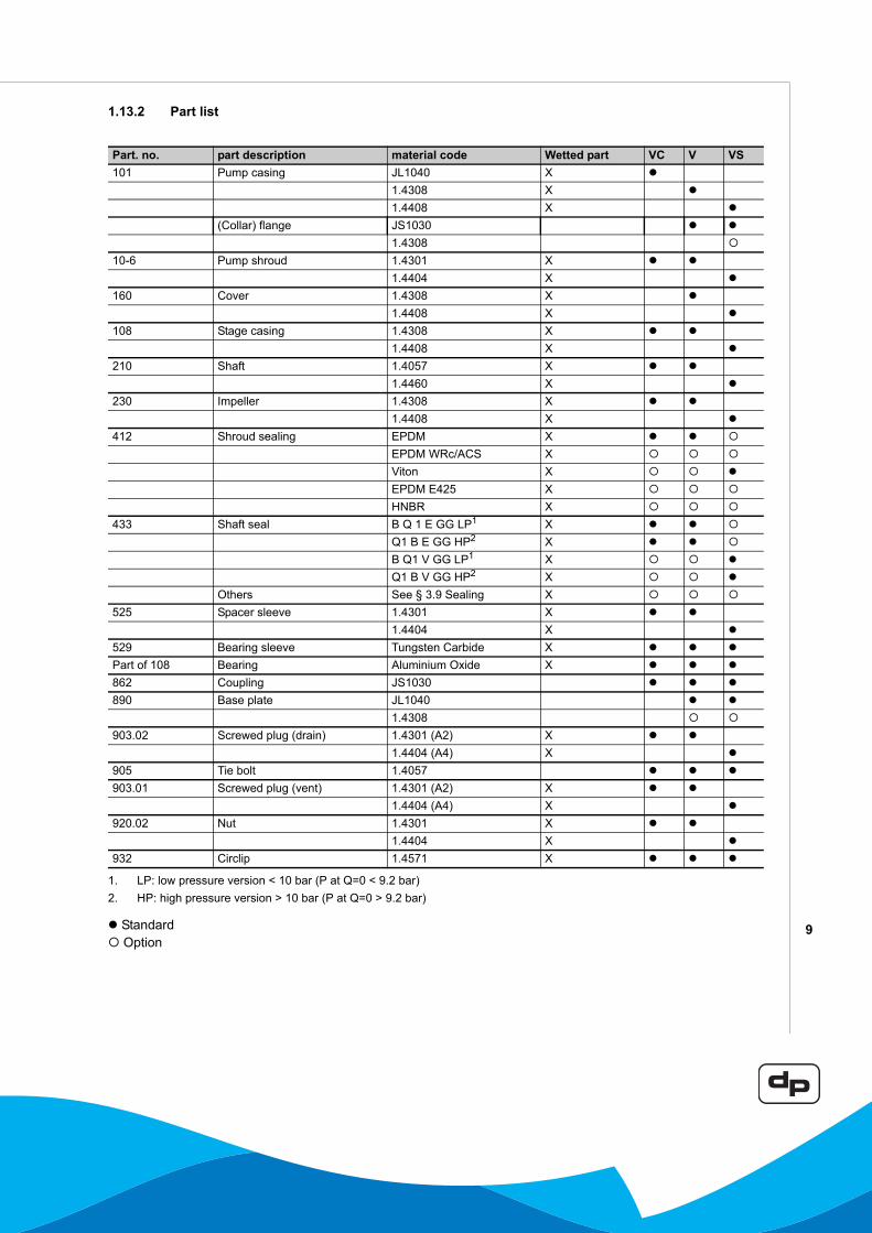
1.13.2 Part list
Standard Option
Part. no. part description material code Wetted part VC V VS101 Pump casing JL1040 X
1.4308 X1.4408 X
(Collar) flange JS10301.4308
10-6 Pump shroud 1.4301 X1.4404 X
160 Cover 1.4308 X1.4408 X
108 Stage casing 1.4308 X1.4408 X
210 Shaft 1.4057 X1.4460 X
230 Impeller 1.4308 X1.4408 X
412 Shroud sealing EPDM XEPDM WRc/ACS XViton XEPDM E425 XHNBR X
433 Shaft seal B Q 1 E GG LP1 XQ1 B E GG HP2 XB Q1 V GG LP1 XQ1 B V GG HP2 X
Others See § 3.9 Sealing X525 Spacer sleeve 1.4301 X
1.4404 X529 Bearing sleeve Tungsten Carbide XPart of 108 Bearing Aluminium Oxide X862 Coupling JS1030890 Base plate JL1040
1.4308903.02 Screwed plug (drain) 1.4301 (A2) X
1.4404 (A4) X905 Tie bolt 1.4057903.01 Screwed plug (vent) 1.4301 (A2) X
1.4404 (A4) X920.02 Nut 1.4301 X
1.4404 X932 Circlip 1.4571 X
1. LP: low pressure version < 10 bar (P at Q=0 < 9.2 bar)2. HP: high pressure version > 10 bar (P at Q=0 > 9.2 bar)
10
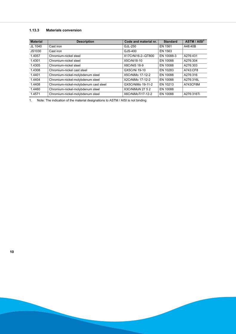
1.13.3 Materials conversion
Material Description Code and material nr. Standard ASTM / AISI1
JL 1040 Cast iron GJL-250 EN 1561 A48:40BJS1030 Cast iron GJS-400 EN 15631.4057 Chromium-nickel steel X17CrNi16-2--QT800 EN 10088-3 A276:4311.4301 Chromium-nickel steel X5CrNi18-10 EN 10088 A276:3041.4305 Chromium-nickel steel X8CrNiS 18-9 EN 10088 A276:3031.4308 Chromium-nickel cast steel GX5CrNi 19-10 EN 10283 A743:CF81.4401 Chromium-nickel-molybdenum steel X5CrNiMo 17-12-2 EN 10088 A276:3161.4404 Chromium-nickel-molybdenum steel X2CrNiMo 17-12-2 EN 10088 A276:316L1.4408 Chromium-nickel-molybdenum cast steel GX5CrNiMo 19-11-2 EN 10213 A743CF8M1.4460 Chromium-nickel-molybdenum steel X3CrNiMoN 27 5 2 EN 100881.4571 Chromium-nickel-molybdenum steel X6CrNiMoTi17-12-2 EN 10088 A276:316Ti
1. Note: The indication of the material designations to ASTM / AISI is not binding
11
2 Performance characteristics
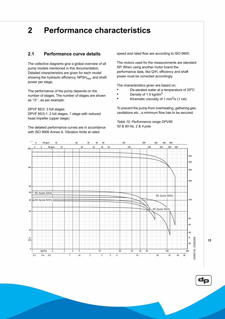
2.1 Performance curve details
The collective diagrams give a global overview of all pump models mentioned in this documentation.Detailed characteristics are given for each model showing the hydraulic efficiency, NPSHreq, and shaft power per stage.
The performance of the pump depends on the number of stages. The number of stages are shown as “/3” , as per example:
DPVF 85/3: 3 full stagesDPVF 85/3-1: 2 full stages, 1 stage with reduced head impeller (upper stage)
The detailed performance curves are in accordance with ISO 9906 Annex A. Vibration limits at rated
speed and rated flow are according to ISO 9905.
The motors used for the measurements are standard DP. When using another motor brand the performance data, like Q/H, efficiency and shaft power must be corrected accordingly.
The characteristics given are based on:• De-aerated water at a temperature of 20oC• Density of 1.0 kg/dm3
• Kinematic viscosity of 1 mm2/s (1 cst)
To prevent the pump from overheating, gathering gas, cavitations etc., a minimum flow has to be secured.
Table 10: Performance range DPV85 50 & 60 Hz, 2 & 4 pole
ID 3264
2008
0730
, 200
8200
8
12
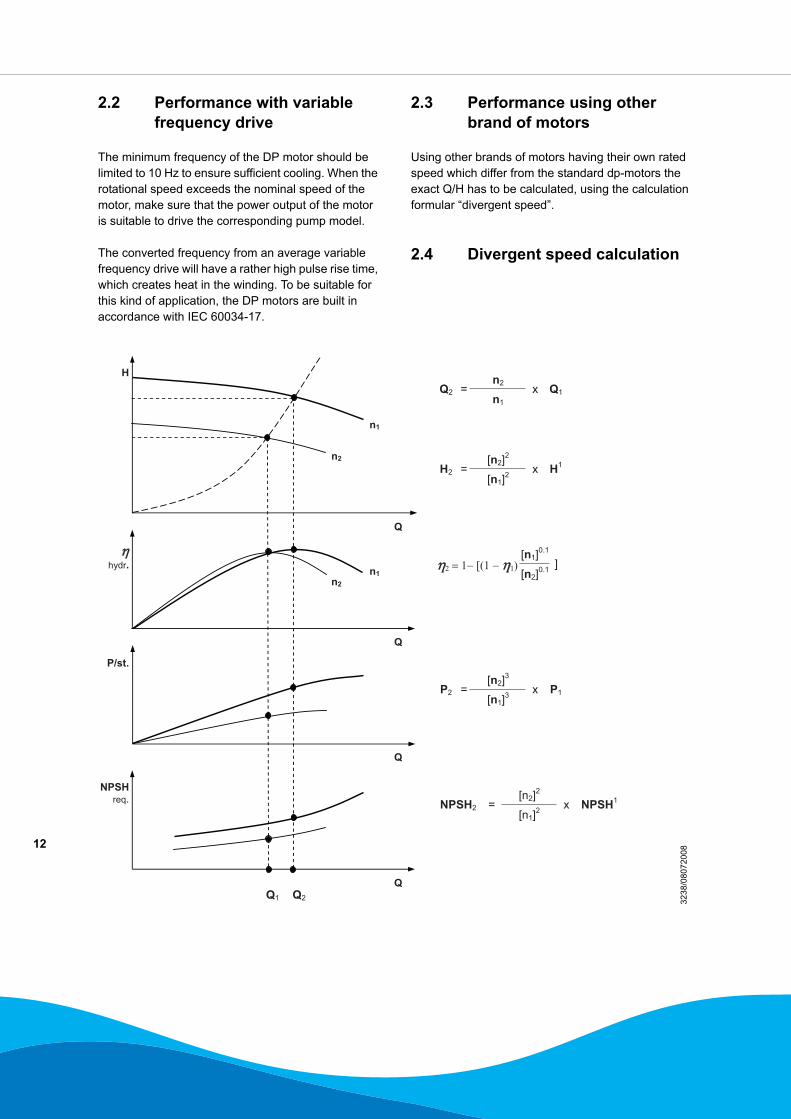
2.2 Performance with variable frequency drive
The minimum frequency of the DP motor should be limited to 10 Hz to ensure sufficient cooling. When the rotational speed exceeds the nominal speed of the motor, make sure that the power output of the motor is suitable to drive the corresponding pump model.
The converted frequency from an average variable frequency drive will have a rather high pulse rise time, which creates heat in the winding. To be suitable for this kind of application, the DP motors are built in accordance with IEC 60034-17.
2.3 Performance using other brand of motors
Using other brands of motors having their own rated speed which differ from the standard dp-motors the exact Q/H has to be calculated, using the calculation formular “divergent speed”.
2.4 Divergent speed calculation
3238
/080
7200
8
13
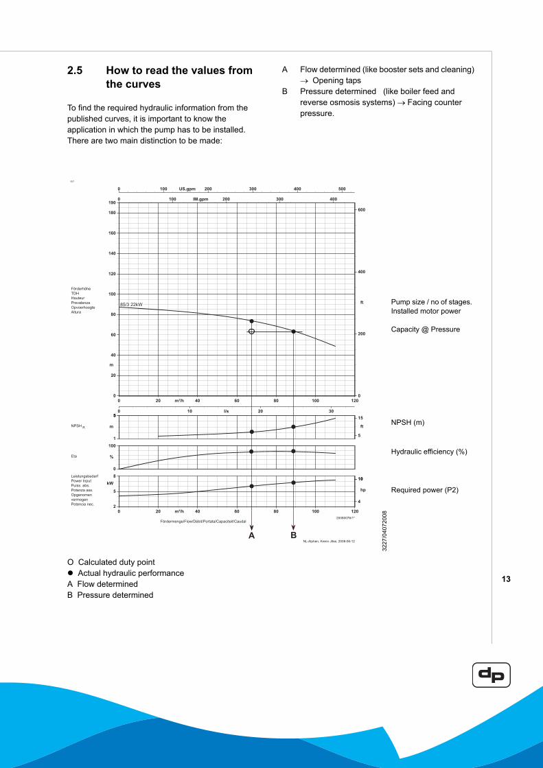
2.5 How to read the values from the curves
To find the required hydraulic information from the published curves, it is important to know the application in which the pump has to be installed.There are two main distinction to be made:
A Flow determined (like booster sets and cleaning) → Opening taps
B Pressure determined (like boiler feed and reverse osmosis systems) → Facing counter pressure.
O Calculated duty point Actual hydraulic performance
A Flow determinedB Pressure determined
3227
3227
/040
7200
8
Pump size / no of stages.Installed motor power
Capacity @ Pressure
NPSH (m)
Hydraulic efficiency (%)
Required power (P2)
14
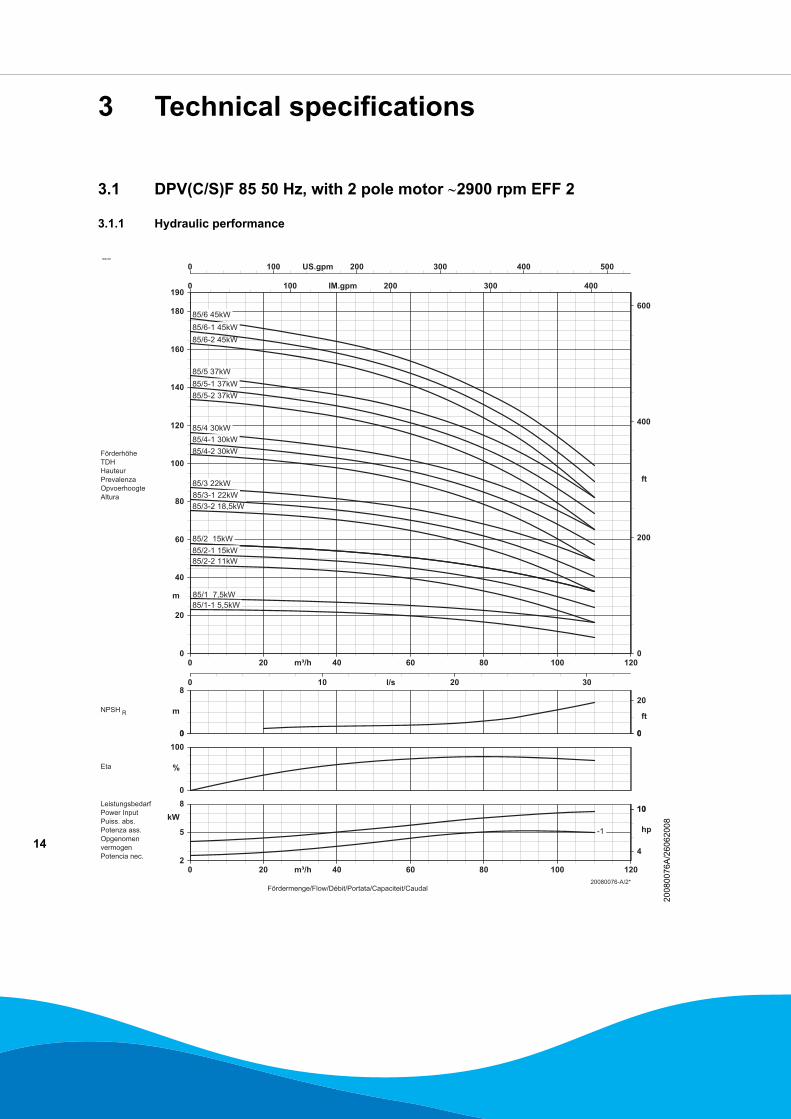
3 Technical specifications
3.1 DPV(C/S)F 85 50 Hz, with 2 pole motor ∼2900 rpm EFF 2
3.1.1 Hydraulic performance
ID3229
2008
0076
A/2
6062
008
15
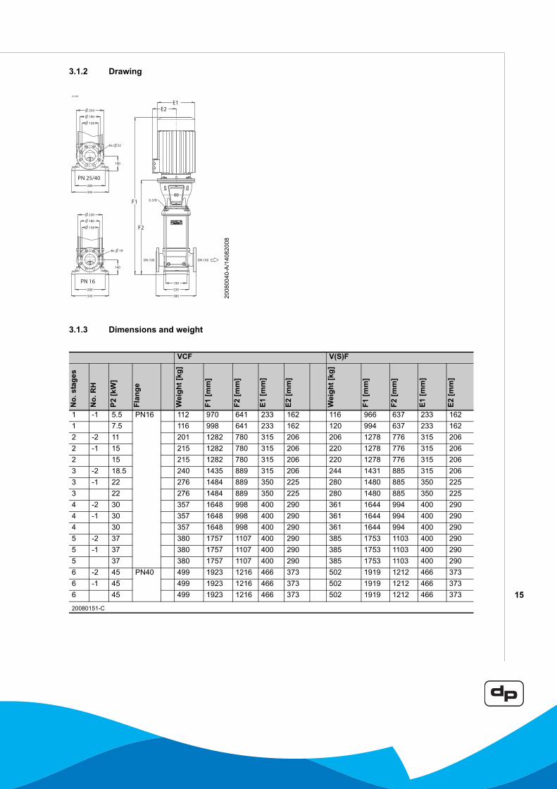
3.1.2 Drawing
3.1.3 Dimensions and weight
ID 3095
2008
0040
-A/1
4082
008
VCF V(S)F
No.
sta
ges
No.
RH
P2 [k
W]
Flan
ge
Wei
ght [
kg]
F1 [m
m]
F2 [m
m]
E1 [m
m]
E2 [m
m]
Wei
ght [
kg]
F1 [m
m]
F2 [m
m]
E1 [m
m]
E2 [m
m]
1 -1 5.5 PN16 112 970 641 233 162 116 966 637 233 1621 7.5 116 998 641 233 162 120 994 637 233 1622 -2 11 201 1282 780 315 206 206 1278 776 315 2062 -1 15 215 1282 780 315 206 220 1278 776 315 2062 15 215 1282 780 315 206 220 1278 776 315 2063 -2 18.5 240 1435 889 315 206 244 1431 885 315 2063 -1 22 276 1484 889 350 225 280 1480 885 350 2253 22 276 1484 889 350 225 280 1480 885 350 2254 -2 30 357 1648 998 400 290 361 1644 994 400 2904 -1 30 357 1648 998 400 290 361 1644 994 400 2904 30 357 1648 998 400 290 361 1644 994 400 2905 -2 37 380 1757 1107 400 290 385 1753 1103 400 2905 -1 37 380 1757 1107 400 290 385 1753 1103 400 2905 37 380 1757 1107 400 290 385 1753 1103 400 2906 -2 45 PN40 499 1923 1216 466 373 502 1919 1212 466 3736 -1 45 499 1923 1216 466 373 502 1919 1212 466 3736 45 499 1923 1216 466 373 502 1919 1212 466 373
20080151-C
16
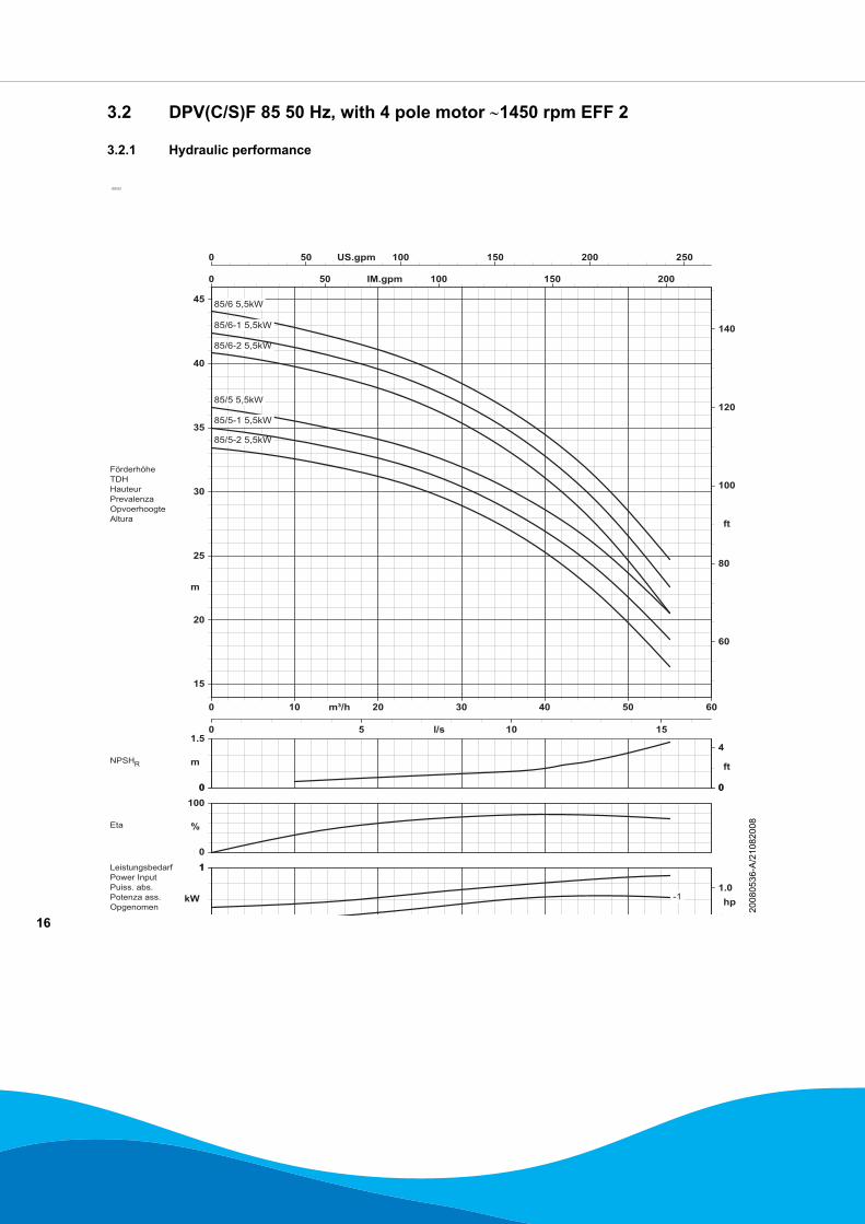
3.2 DPV(C/S)F 85 50 Hz, with 4 pole motor ∼1450 rpm EFF 2
3.2.1 Hydraulic performance
ID3233
2008
0536
-A/2
1082
008
17
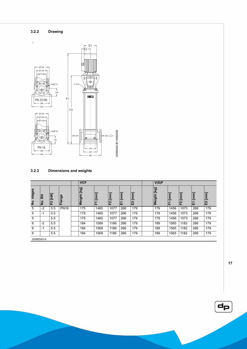
3.2.2 Drawing
3.2.3 Dimensions and weights
3235
2008
0542
-B/1
4082
008
VCF V(S)F
No.
sta
ges
No.
RH
P2 [k
W]
Flan
ge
Wei
ght [
kg]
F1 [m
m]
F2 [m
m]
E1 [m
m]
E2 [m
m]
Wei
ght [
kg]
F1 [m
m]
F2 [m
m]
E1 [m
m]
E2 [m
m]
5 -2 5.5 PN16 175 1460 1077 266 179 179 1456 1073 266 1795 -1 5.5 175 1460 1077 266 179 179 1456 1073 266 1795 5.5 175 1460 1077 266 179 179 1456 1073 266 1796 -2 5.5 184 1569 1186 266 179 189 1565 1182 266 1796 -1 5.5 184 1569 1186 266 179 189 1565 1182 266 1796 5.5 184 1569 1186 266 179 189 1565 1182 266 179
20080540-A
18
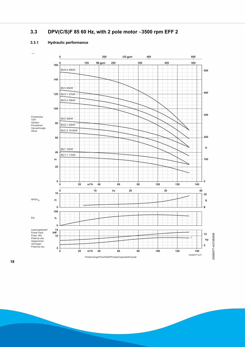
3.3 DPV(C/S)F 85 60 Hz, with 2 pole motor ∼3500 rpm EFF 2
3.3.1 Hydraulic performance
ID3090
2008
0077
-A/2
1082
008
19
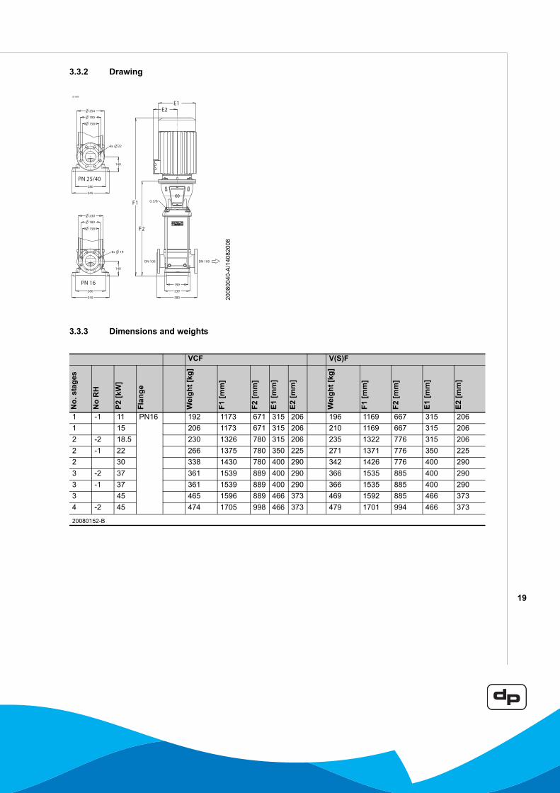
3.3.2 Drawing
3.3.3 Dimensions and weights
ID 3095
2008
0040
-A/1
4082
008
VCF V(S)F
No.
sta
ges
No
RH
P2 [k
W]
Flan
ge
Wei
ght [
kg]
F1 [m
m]
F2 [m
m]
E1 [m
m]
E2 [m
m]
Wei
ght [
kg]
F1 [m
m]
F2 [m
m]
E1 [m
m]
E2 [m
m]
1 -1 11 PN16 192 1173 671 315 206 196 1169 667 315 2061 15 206 1173 671 315 206 210 1169 667 315 2062 -2 18.5 230 1326 780 315 206 235 1322 776 315 2062 -1 22 266 1375 780 350 225 271 1371 776 350 2252 30 338 1430 780 400 290 342 1426 776 400 2903 -2 37 361 1539 889 400 290 366 1535 885 400 2903 -1 37 361 1539 889 400 290 366 1535 885 400 2903 45 465 1596 889 466 373 469 1592 885 466 3734 -2 45 474 1705 998 466 373 479 1701 994 466 373
20080152-B
20
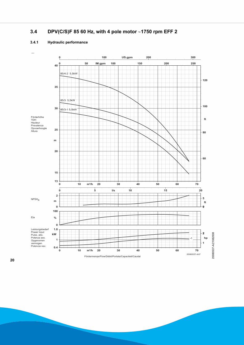
3.4 DPV(C/S)F 85 60 Hz, with 4 pole motor ∼1750 rpm EFF 2
3.4.1 Hydraulic performance
ID3234
2008
0537
-A/2
1082
008
21
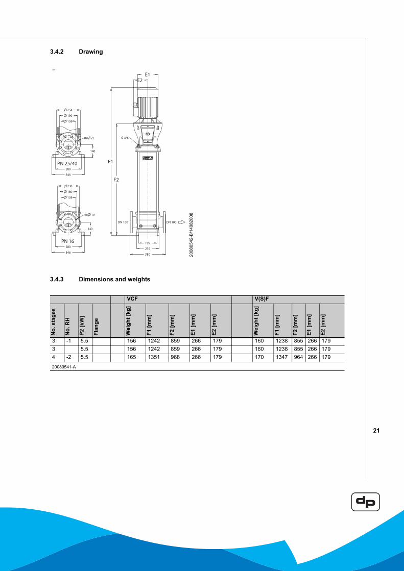
3.4.2 Drawing
3.4.3 Dimensions and weights
3235
2008
0542
-B/1
4082
008
VCF V(S)F
No.
sta
ges
No.
RH
P2 [k
W]
Flan
ge
Wei
ght [
kg]
F1 [m
m]
F2 [m
m]
E1 [m
m]
E2 [m
m]
Wei
ght [
kg]
F1 [m
m]
F2 [m
m]
E1 [m
m]
E2 [m
m]
3 -1 5.5 156 1242 859 266 179 160 1238 855 266 1793 5.5 156 1242 859 266 179 160 1238 855 266 1794 -2 5.5 165 1351 968 266 179 170 1347 964 266 179
20080541-A
22
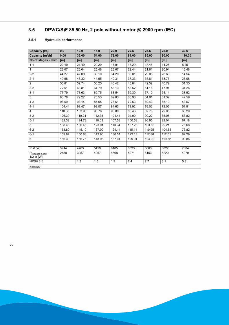
3.5 DPV(C/S)F 85 50 Hz, 2 pole without motor @ 2900 rpm (IEC)
3.5.1 Hydraulic performance
Capacity [l/s] 0.0 10.0 15.0 20.0 22.5 23.6 25.0 30.6Capacity [m3/h] 0.00 36.00 54.00 72.00 81.00 85.00 90.00 110.00No of stages \ mwc [m] [m] [m] [m] [m] [m] [m] [m]1-1 22.49 21.49 20.20 17.91 16.29 15.45 14.28 8.251 28.07 26.64 25.48 23.67 22.44 21.81 20.94 16.482-2 44.27 42.00 39.10 34.20 30.81 29.08 26.69 14.542-1 49.98 47.32 44.65 40.31 37.33 35.81 33.73 23.082 55.81 52.74 50.25 46.42 43.84 42.52 40.72 31.553-2 72.51 68.81 64.79 58.13 53.52 51.16 47.91 31.263-1 77.79 73.63 69.75 63.54 59.30 57.12 54.14 38.923 83.78 79.22 75.53 69.83 65.98 64.01 61.32 47.594-2 98.69 93.14 87.55 78.61 72.53 69.43 65.19 43.674-1 104.44 98.47 93.07 84.63 78.92 76.02 72.05 51.914 110.38 103.98 98.76 90.80 85.46 82.76 79.05 60.295-2 126.39 119.24 112.35 101.41 94.00 90.22 85.05 58.825-1 132.32 124.73 118.03 107.58 100.53 96.95 92.04 67.185 138.48 130.45 123.91 113.94 107.25 103.85 99.21 75.686-2 153.80 145.10 137.00 124.14 115.41 110.95 104.85 73.826-1 159.94 150.83 142.90 130.51 122.13 117.86 112.01 82.296 166.30 156.75 148.98 137.04 129.01 124.92 119.32 90.86
P st [W] 3914 4763 5459 6185 6523 6663 6827 7304Preduced head 1/2 st [W]
2458 3257 4067 4808 5071 5153 5220 4979
NPSH [m] 1.3 1.5 1.9 2.4 2.7 3.1 5.8
20080617
23
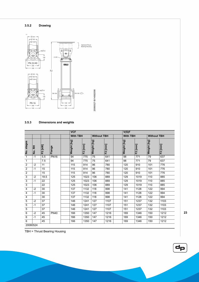
3.5.2 Drawing
3.5.3 Dimensions and weights
TBH = Thrust Bearing Housing
3236
2008
0527
-B/1
4082
008
VCF V(S)FWith TBH Without TBH With TBH Without TBH
No.
sta
ges
No.
RH
P2 [k
W]
Flan
ge
Wei
ght [
kg]
F2 [m
m]
Wei
ght [
kg]
F2 [m
m]
Wei
ght [
kg]
F2 [m
m]
Wei
ght [
kg]
F2 [m
m]
1 -1 5.5 PN16 94 775 75 641 98 771 79 6371 7.5 94 775 75 641 98 771 79 6372 -2 11 115 914 96 780 120 910 101 7762 -1 15 115 914 96 780 120 910 101 7762 15 115 914 96 780 120 910 101 7763 -2 18.5 125 1023 106 889 129 1019 110 8853 -1 22 125 1023 106 889 129 1019 110 8853 22 125 1023 106 889 129 1019 110 8854 -2 30 137 1132 118 998 141 1128 122 9944 -1 30 137 1132 118 998 141 1128 122 9944 30 137 1132 118 998 141 1128 122 9945 -2 37 146 1241 127 1107 151 1237 132 11035 -1 37 146 1241 127 1107 151 1237 132 11035 37 146 1241 127 1107 151 1237 132 11036 -2 45 PN40 166 1350 147 1216 169 1346 150 12126 -1 45 166 1350 147 1216 169 1346 150 12126 45 166 1350 147 1216 169 1346 150 121220080524
24
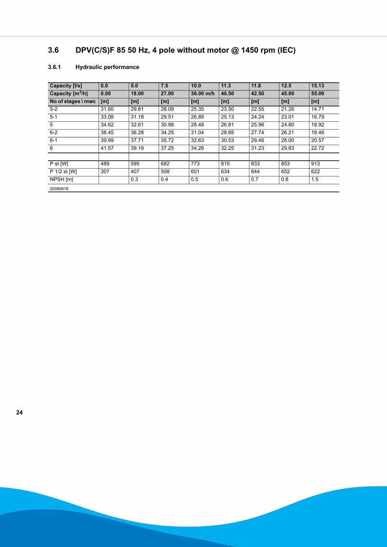
3.6 DPV(C/S)F 85 50 Hz, 4 pole without motor @ 1450 rpm (IEC)
3.6.1 Hydraulic performance
Capacity [l/s] 0.0 5.0 7.5 10.0 11.3 11.8 12.5 15.13Capacity [m3/h] 0.00 18.00 27.00 36.00 m/h 40.50 42.50 45.00 55.00No of stages \ mwc [m] [m] [m] [m] [m] [m] [m] [m]5-2 31.60 29.81 28.09 25.35 23.50 22.55 21.26 14.715-1 33.08 31.18 29.51 26.89 25.13 24.24 23.01 16.795 34.62 32.61 30.98 28.48 26.81 25.96 24.80 18.926-2 38.45 36.28 34.25 31.04 28.85 27.74 26.21 18.466-1 39.99 37.71 35.72 32.63 30.53 29.46 28.00 20.576 41.57 39.19 37.25 34.26 32.25 31.23 29.83 22.72
P st [W] 489 595 682 773 815 833 853 913P 1/2 st [W] 307 407 508 601 634 644 652 622NPSH [m] 0.3 0.4 0.5 0.6 0.7 0.8 1.5
20080618

25
3.6.2 Drawing
3.6.3 Dimensions and weightsOn request
3236
2008
0527
-B/1
4082
008
26
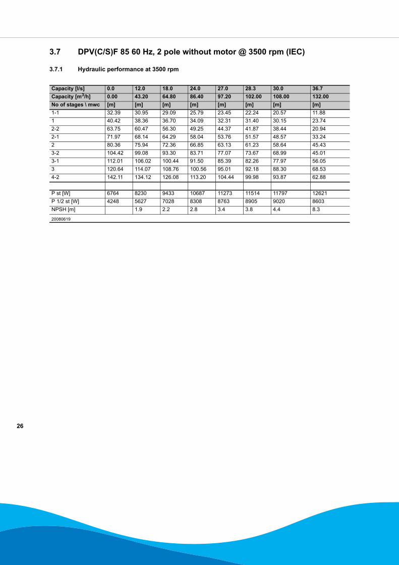
3.7 DPV(C/S)F 85 60 Hz, 2 pole without motor @ 3500 rpm (IEC)
3.7.1 Hydraulic performance at 3500 rpm
Capacity [l/s] 0.0 12.0 18.0 24.0 27.0 28.3 30.0 36.7Capacity [m3/h] 0.00 43.20 64.80 86.40 97.20 102.00 108.00 132.00No of stages \ mwc [m] [m] [m] [m] [m] [m] [m] [m]1-1 32.39 30.95 29.09 25.79 23.45 22.24 20.57 11.881 40.42 38.36 36.70 34.09 32.31 31.40 30.15 23.742-2 63.75 60.47 56.30 49.25 44.37 41.87 38.44 20.942-1 71.97 68.14 64.29 58.04 53.76 51.57 48.57 33.242 80.36 75.94 72.36 66.85 63.13 61.23 58.64 45.433-2 104.42 99.08 93.30 83.71 77.07 73.67 68.99 45.013-1 112.01 106.02 100.44 91.50 85.39 82.26 77.97 56.053 120.64 114.07 108.76 100.56 95.01 92.18 88.30 68.534-2 142.11 134.12 126.08 113.20 104.44 99.98 93.87 62.88
P st [W] 6764 8230 9433 10687 11273 11514 11797 12621P 1/2 st [W] 4248 5627 7028 8308 8763 8905 9020 8603NPSH [m] 1.9 2.2 2.8 3.4 3.8 4.4 8.3
20080619
27
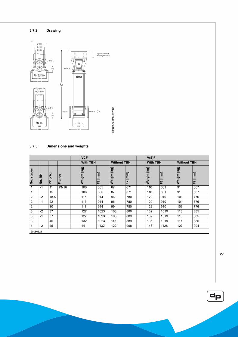
3.7.2 Drawing
3.7.3 Dimensions and weights
3236
2008
0527
-B/1
4082
008
VCF V(S)FWith TBH Without TBH With TBH Without TBH
No.
sta
ges
No.
RH
P2 [k
W]
Flan
ge
Wei
ght [
kg]
F2 [m
m]
Wei
ght [
kg]
F2 [m
m]
Wei
ght [
kg]
F2 [m
m]
Wei
ght [
kg]
F2 [m
m]
1 -1 11 PN16 106 805 87 671 110 801 91 6671 15 106 805 87 671 110 801 91 6672 -2 18.5 115 914 96 780 120 910 101 7762 -1 22 115 914 96 780 120 910 101 7762 30 118 914 99 780 122 910 103 7763 -2 37 127 1023 108 889 132 1019 113 8853 -1 37 127 1023 108 889 132 1019 113 8853 45 132 1023 113 889 136 1019 117 8854 -2 45 141 1132 122 998 146 1128 127 994
20080525
28
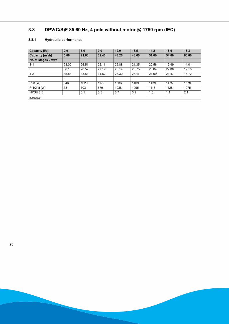
3.8 DPV(C/S)F 85 60 Hz, 4 pole without motor @ 1750 rpm (IEC)
3.8.1 Hydraulic performance
Capacity [l/s] 0.0 6.0 9.0 12.0 13.5 14.2 15.0 18.3Capacity [m3/h] 0.00 21.60 32.40 43.20 48.60 51.00 54.00 66.00No of stages \ mwc3-1 28.00 26.51 25.11 22.88 21.35 20.56 19.49 14.013 30.16 28.52 27.19 25.14 23.75 23.04 22.08 17.134-2 35.53 33.53 31.52 28.30 26.11 24.99 23.47 15.72
P st [W] 846 1029 1179 1336 1409 1439 1475 1578P 1/2 st [W] 531 703 879 1038 1095 1113 1128 1075NPSH [m] 0.5 0.5 0.7 0.9 1.0 1.1 2.1
20080620
29
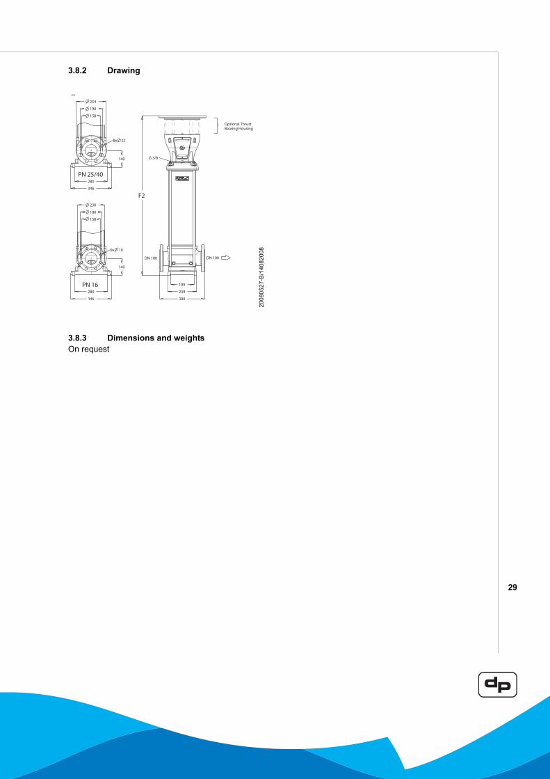
3.8.2 Drawing
3.8.3 Dimensions and weightsOn request
3236
2008
0527
-B/1
4082
008
30
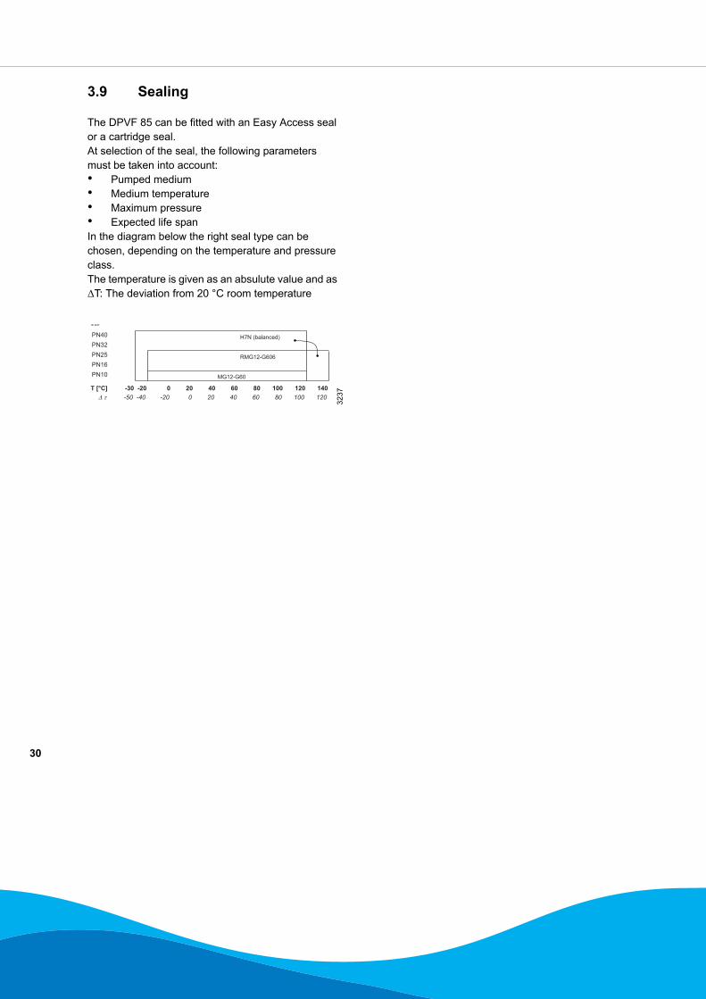
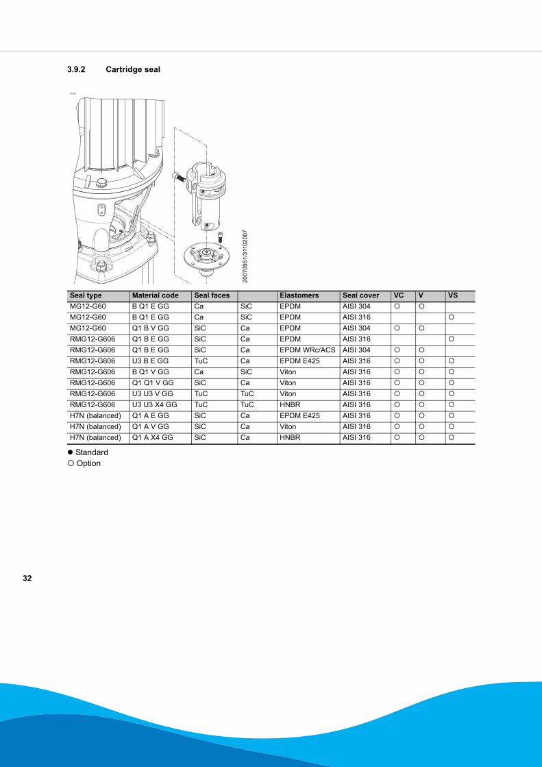
3.9 Sealing
The DPVF 85 can be fitted with an Easy Access seal or a cartridge seal.At selection of the seal, the following parameters must be taken into account:• Pumped medium• Medium temperature• Maximum pressure• Expected life spanIn the diagram below the right seal type can be chosen, depending on the temperature and pressure class.The temperature is given as an absulute value and as ΔT: The deviation from 20 °C room temperature
ID 3237
3237
31
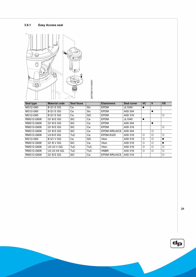
3.9.1 Easy Access seal
ID3029
2007
0951
/311
0200
7
Seal type Material code Seal faces Elastomers Seal cover VC V VSMG12-G60 B Q1 E GG Ca Sic EPDM JL1040MG12-G60 B Q1 E GG Ca Sic EPDM AISI 304MG12-G60 B Q1 E GG Ca SiC EPDM AISI 316RMG12-G606 Q1 B E GG SiC Ca EPDM JL1040RMG12-G606 Q1 B E GG SiC Ca EPDM AISI 304RMG12-G606 Q1 B E GG SiC Ca EPDM AISI 316RMG12-G606 Q1 B E GG SiC Ca EPDM WRc/ACS AISI 304RMG12-G606 U3 B E GG TuC Ca EPDM E425 AISI 316MG12-G60 B Q1 V GG Ca SiC Viton AISI 316RMG12-G606 Q1 B V GG SiC Ca Viton AISI 316RMG12-G606 U3 U3 V GG TuC TuC Viton AISI 316RMG12-G606 U3 U3 X4 GG TuC TuC HNBR AISI 316RMG12-G606 Q1 B E GG SiC Ca EPDM WRc/ACS AISI 316
32
3.9.2 Cartridge seal
Standard Option
ID3028
2007
0951
/311
0200
7
Seal type Material code Seal faces Elastomers Seal cover VC V VSMG12-G60 B Q1 E GG Ca SiC EPDM AISI 304MG12-G60 B Q1 E GG Ca SiC EPDM AISI 316MG12-G60 Q1 B V GG SiC Ca EPDM AISI 304RMG12-G606 Q1 B E GG SiC Ca EPDM AISI 316RMG12-G606 Q1 B E GG SiC Ca EPDM WRc/ACS AISI 304RMG12-G606 U3 B E GG TuC Ca EPDM E425 AISI 316RMG12-G606 B Q1 V GG Ca SiC Viton AISI 316RMG12-G606 Q1 Q1 V GG SiC Ca Viton AISI 316RMG12-G606 U3 U3 V GG TuC TuC Viton AISI 316RMG12-G606 U3 U3 X4 GG TuC TuC HNBR AISI 316H7N (balanced) Q1 A E GG SiC Ca EPDM E425 AISI 316H7N (balanced) Q1 A V GG SiC Ca Viton AISI 316H7N (balanced) Q1 A X4 GG SiC Ca HNBR AISI 316
33
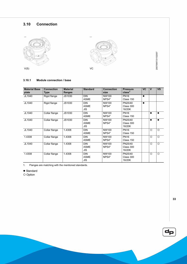
3.10 Connection
3.10.1 Module connection / base
Standard Option
ID3049 ID3050
2007
0947
/311
0200
7
V(S) VC
Material Base plate
Connection Type
Material flanges
Standard Connection size
Pressure class1
VC V VS
JL1040 Rigid flange JS1030 DINASME
NW100NPS4"
PN16Class 150
JL1040 Rigid flange JS1030 DINASMEJIS
NW100NPS4"
PN25/40Class 30016/20K
JL1040 Collar flange JS1030 DINASME
NW100NPS4"
PN16Class 150
JL1040 Collar flange JS1030 DINASMEJIS
NW100NPS4"
PN25/40Class 30016/20K
JL1040 Collar flange 1.4308 DINASME
NW100NPS4"
PN16Class 150
1.4308 Collar flange 1.4308 DINASME
NW100NPS4"
PN16Class 150
JL1040 Collar flange 1.4308 DINASMEJIS
NW100NPS4"
PN25/40Class 300 16/20K
1.4308 Collar flange 1.4308 DINASMEJIS
NW100NPS4"
PN25/40 Class 300 16/20K
1. Flanges are matching with the mentioned standards.
34
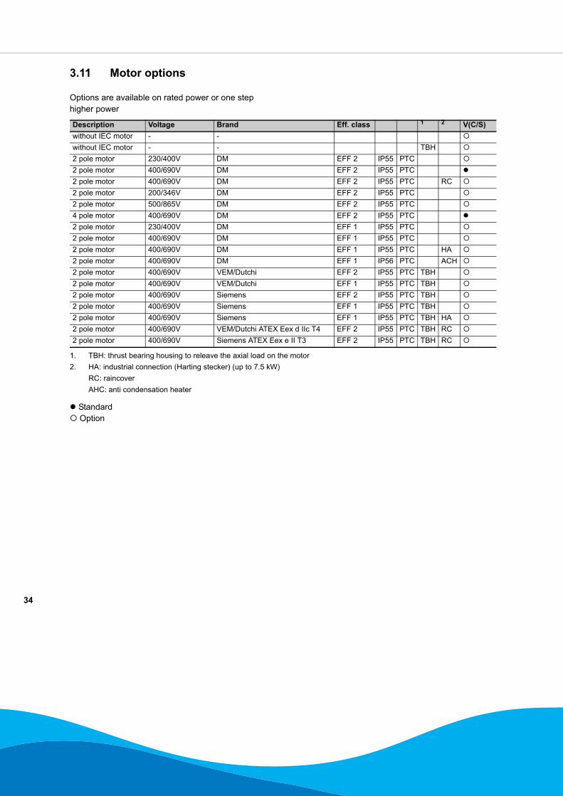
3.11 Motor options
Options are available on rated power or one step higher power
Standard Option
Description Voltage Brand Eff. class 1 2 V(C/S)without IEC motor - -without IEC motor - - TBH2 pole motor 230/400V DM EFF 2 IP55 PTC2 pole motor 400/690V DM EFF 2 IP55 PTC2 pole motor 400/690V DM EFF 2 IP55 PTC RC2 pole motor 200/346V DM EFF 2 IP55 PTC2 pole motor 500/865V DM EFF 2 IP55 PTC4 pole motor 400/690V DM EFF 2 IP55 PTC2 pole motor 230/400V DM EFF 1 IP55 PTC2 pole motor 400/690V DM EFF 1 IP55 PTC2 pole motor 400/690V DM EFF 1 IP55 PTC HA2 pole motor 400/690V DM EFF 1 IP56 PTC ACH2 pole motor 400/690V VEM/Dutchi EFF 2 IP55 PTC TBH2 pole motor 400/690V VEM/Dutchi EFF 1 IP55 PTC TBH2 pole motor 400/690V Siemens EFF 2 IP55 PTC TBH2 pole motor 400/690V Siemens EFF 1 IP55 PTC TBH2 pole motor 400/690V Siemens EFF 1 IP55 PTC TBH HA2 pole motor 400/690V VEM/Dutchi ATEX Eex d IIc T4 EFF 2 IP55 PTC TBH RC2 pole motor 400/690V Siemens ATEX Eex e II T3 EFF 2 IP55 PTC TBH RC
1. TBH: thrust bearing housing to releave the axial load on the motor2. HA: industrial connection (Harting stecker) (up to 7.5 kW)
RC: raincoverAHC: anti condensation heater
35
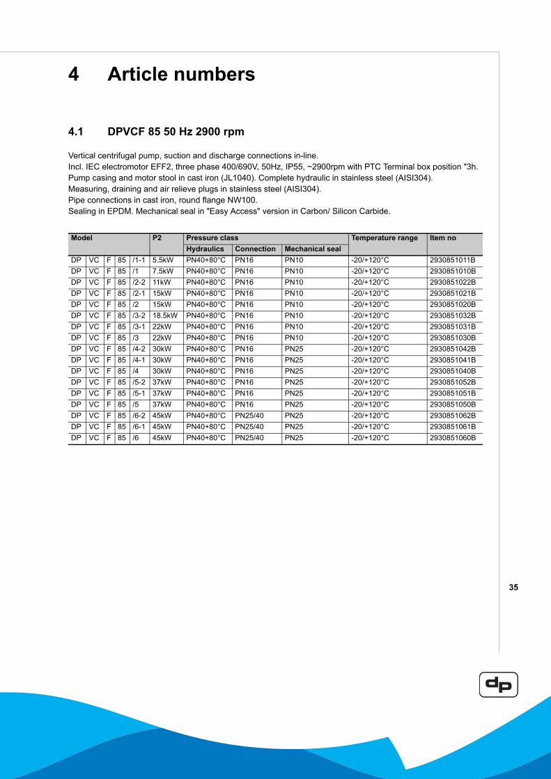
4 Article numbers
4.1 DPVCF 85 50 Hz 2900 rpm
Vertical centrifugal pump, suction and discharge connections in-line.Incl. IEC electromotor EFF2, three phase 400/690V, 50Hz, IP55, ~2900rpm with PTC Terminal box position "3h.Pump casing and motor stool in cast iron (JL1040). Complete hydraulic in stainless steel (AISI304).Measuring, draining and air relieve plugs in stainless steel (AISI304).Pipe connections in cast iron, round flange NW100.Sealing in EPDM. Mechanical seal in "Easy Access" version in Carbon/ Silicon Carbide.
Model P2 Pressure class Temperature range Item noHydraulics Connection Mechanical seal
DP VC F 85 /1-1 5.5kW PN40+80°C PN16 PN10 -20/+120°C 2930851011BDP VC F 85 /1 7.5kW PN40+80°C PN16 PN10 -20/+120°C 2930851010BDP VC F 85 /2-2 11kW PN40+80°C PN16 PN10 -20/+120°C 2930851022BDP VC F 85 /2-1 15kW PN40+80°C PN16 PN10 -20/+120°C 2930851021BDP VC F 85 /2 15kW PN40+80°C PN16 PN10 -20/+120°C 2930851020BDP VC F 85 /3-2 18.5kW PN40+80°C PN16 PN10 -20/+120°C 2930851032BDP VC F 85 /3-1 22kW PN40+80°C PN16 PN10 -20/+120°C 2930851031BDP VC F 85 /3 22kW PN40+80°C PN16 PN10 -20/+120°C 2930851030BDP VC F 85 /4-2 30kW PN40+80°C PN16 PN25 -20/+120°C 2930851042BDP VC F 85 /4-1 30kW PN40+80°C PN16 PN25 -20/+120°C 2930851041BDP VC F 85 /4 30kW PN40+80°C PN16 PN25 -20/+120°C 2930851040BDP VC F 85 /5-2 37kW PN40+80°C PN16 PN25 -20/+120°C 2930851052BDP VC F 85 /5-1 37kW PN40+80°C PN16 PN25 -20/+120°C 2930851051BDP VC F 85 /5 37kW PN40+80°C PN16 PN25 -20/+120°C 2930851050BDP VC F 85 /6-2 45kW PN40+80°C PN25/40 PN25 -20/+120°C 2930851062BDP VC F 85 /6-1 45kW PN40+80°C PN25/40 PN25 -20/+120°C 2930851061BDP VC F 85 /6 45kW PN40+80°C PN25/40 PN25 -20/+120°C 2930851060B
36
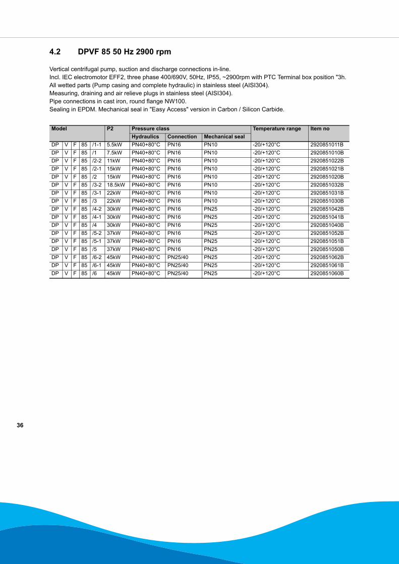
4.2 DPVF 85 50 Hz 2900 rpm
Vertical centrifugal pump, suction and discharge connections in-line.Incl. IEC electromotor EFF2, three phase 400/690V, 50Hz, IP55, ~2900rpm with PTC Terminal box position "3h.All wetted parts (Pump casing and complete hydraulic) in stainless steel (AISI304).Measuring, draining and air relieve plugs in stainless steel (AISI304).Pipe connections in cast iron, round flange NW100.Sealing in EPDM. Mechanical seal in "Easy Access" version in Carbon / Silicon Carbide.
Model P2 Pressure class Temperature range Item noHydraulics Connection Mechanical seal
DP V F 85 /1-1 5.5kW PN40+80°C PN16 PN10 -20/+120°C 2920851011BDP V F 85 /1 7.5kW PN40+80°C PN16 PN10 -20/+120°C 2920851010BDP V F 85 /2-2 11kW PN40+80°C PN16 PN10 -20/+120°C 2920851022BDP V F 85 /2-1 15kW PN40+80°C PN16 PN10 -20/+120°C 2920851021BDP V F 85 /2 15kW PN40+80°C PN16 PN10 -20/+120°C 2920851020BDP V F 85 /3-2 18.5kW PN40+80°C PN16 PN10 -20/+120°C 2920851032BDP V F 85 /3-1 22kW PN40+80°C PN16 PN10 -20/+120°C 2920851031BDP V F 85 /3 22kW PN40+80°C PN16 PN10 -20/+120°C 2920851030BDP V F 85 /4-2 30kW PN40+80°C PN16 PN25 -20/+120°C 2920851042BDP V F 85 /4-1 30kW PN40+80°C PN16 PN25 -20/+120°C 2920851041BDP V F 85 /4 30kW PN40+80°C PN16 PN25 -20/+120°C 2920851040BDP V F 85 /5-2 37kW PN40+80°C PN16 PN25 -20/+120°C 2920851052BDP V F 85 /5-1 37kW PN40+80°C PN16 PN25 -20/+120°C 2920851051BDP V F 85 /5 37kW PN40+80°C PN16 PN25 -20/+120°C 2920851050BDP V F 85 /6-2 45kW PN40+80°C PN25/40 PN25 -20/+120°C 2920851062BDP V F 85 /6-1 45kW PN40+80°C PN25/40 PN25 -20/+120°C 2920851061BDP V F 85 /6 45kW PN40+80°C PN25/40 PN25 -20/+120°C 2920851060B
37
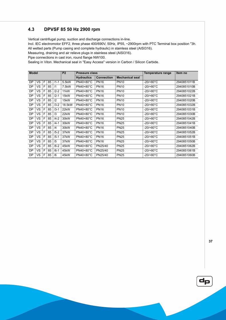
4.3 DPVSF 85 50 Hz 2900 rpm
Vertical centrifugal pump, suction and discharge connections in-line.Incl. IEC electromotor EFF2, three phase 400/690V, 50Hz, IP55, ~2900rpm with PTC Terminal box position "3h.All wetted parts (Pump casing and complete hydraulic) in stainless steel (AISI316).Measuring, draining and air relieve plugs in stainless steel (AISI316).Pipe connections in cast iron, round flange NW100.Sealing in Viton. Mechanical seal in "Easy Access" version in Carbon / Silicon Carbide.
Model P2 Pressure class Temperature range Item noHydraulics Connection Mechanical seal
DP VS F 85 /1-1 5.5kW PN40+80°C PN16 PN10 -20/+80°C 2940851011BDP VS F 85 /1 7.5kW PN40+80°C PN16 PN10 -20/+80°C 2940851010BDP VS F 85 /2-2 11kW PN40+80°C PN16 PN10 -20/+80°C 2940851022BDP VS F 85 /2-1 15kW PN40+80°C PN16 PN10 -20/+80°C 2940851021BDP VS F 85 /2 15kW PN40+80°C PN16 PN10 -20/+80°C 2940851020BDP VS F 85 /3-2 18.5kW PN40+80°C PN16 PN10 -20/+80°C 2940851032BDP VS F 85 /3-1 22kW PN40+80°C PN16 PN10 -20/+80°C 2940851031BDP VS F 85 /3 22kW PN40+80°C PN16 PN10 -20/+80°C 2940851030BDP VS F 85 /4-2 30kW PN40+80°C PN16 PN25 -20/+80°C 2940851042BDP VS F 85 /4-1 30kW PN40+80°C PN16 PN25 -20/+80°C 2940851041BDP VS F 85 /4 30kW PN40+80°C PN16 PN25 -20/+80°C 2940851040BDP VS F 85 /5-2 37kW PN40+80°C PN16 PN25 -20/+80°C 2940851052BDP VS F 85 /5-1 37kW PN40+80°C PN16 PN25 -20/+80°C 2940851051BDP VS F 85 /5 37kW PN40+80°C PN16 PN25 -20/+80°C 2940851050BDP VS F 85 /6-2 45kW PN40+80°C PN25/40 PN25 -20/+80°C 2940851062BDP VS F 85 /6-1 45kW PN40+80°C PN25/40 PN25 -20/+80°C 2940851061BDP VS F 85 /6 45kW PN40+80°C PN25/40 PN25 -20/+80°C 2940851060B
38
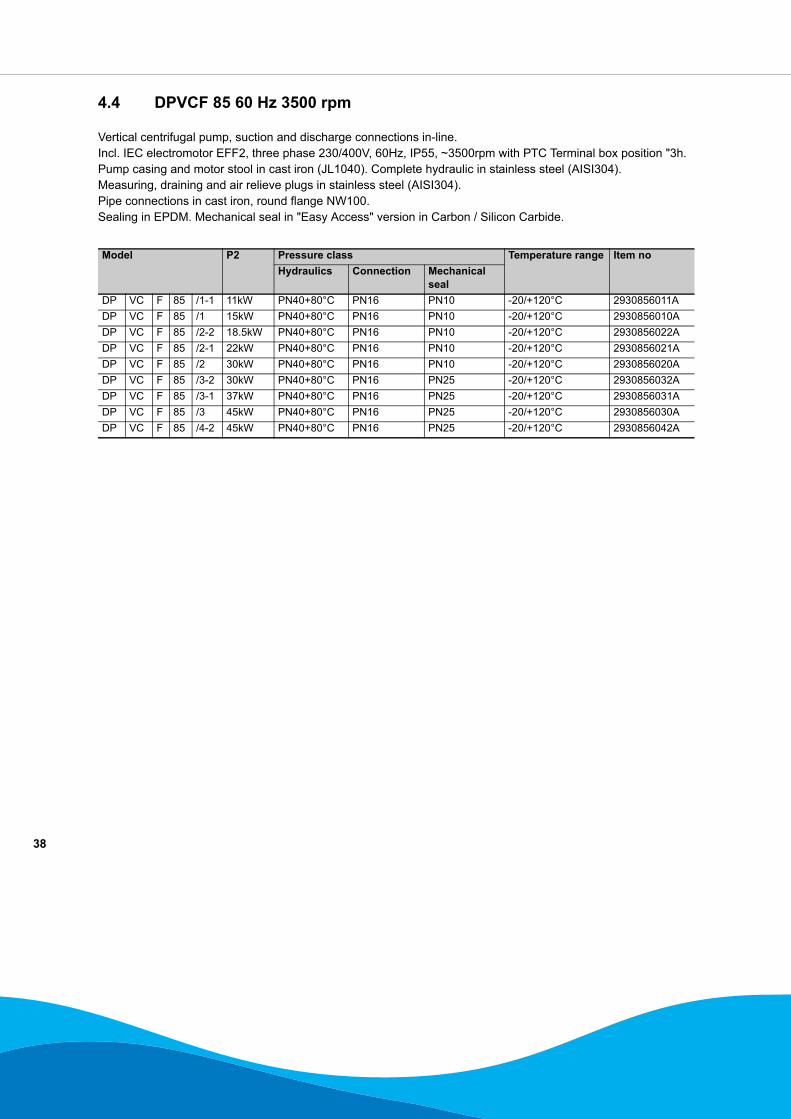
4.4 DPVCF 85 60 Hz 3500 rpm
Vertical centrifugal pump, suction and discharge connections in-line.Incl. IEC electromotor EFF2, three phase 230/400V, 60Hz, IP55, ~3500rpm with PTC Terminal box position "3h.Pump casing and motor stool in cast iron (JL1040). Complete hydraulic in stainless steel (AISI304).Measuring, draining and air relieve plugs in stainless steel (AISI304).Pipe connections in cast iron, round flange NW100.Sealing in EPDM. Mechanical seal in "Easy Access" version in Carbon / Silicon Carbide.
Model P2 Pressure class Temperature range Item noHydraulics Connection Mechanical
sealDP VC F 85 /1-1 11kW PN40+80°C PN16 PN10 -20/+120°C 2930856011ADP VC F 85 /1 15kW PN40+80°C PN16 PN10 -20/+120°C 2930856010ADP VC F 85 /2-2 18.5kW PN40+80°C PN16 PN10 -20/+120°C 2930856022ADP VC F 85 /2-1 22kW PN40+80°C PN16 PN10 -20/+120°C 2930856021ADP VC F 85 /2 30kW PN40+80°C PN16 PN10 -20/+120°C 2930856020ADP VC F 85 /3-2 30kW PN40+80°C PN16 PN25 -20/+120°C 2930856032ADP VC F 85 /3-1 37kW PN40+80°C PN16 PN25 -20/+120°C 2930856031ADP VC F 85 /3 45kW PN40+80°C PN16 PN25 -20/+120°C 2930856030ADP VC F 85 /4-2 45kW PN40+80°C PN16 PN25 -20/+120°C 2930856042A
39
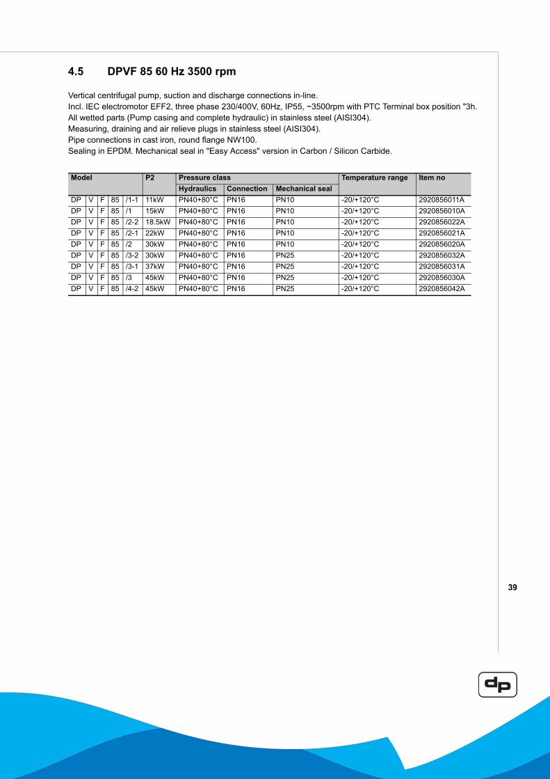
4.5 DPVF 85 60 Hz 3500 rpm
Vertical centrifugal pump, suction and discharge connections in-line.Incl. IEC electromotor EFF2, three phase 230/400V, 60Hz, IP55, ~3500rpm with PTC Terminal box position "3h.All wetted parts (Pump casing and complete hydraulic) in stainless steel (AISI304).Measuring, draining and air relieve plugs in stainless steel (AISI304).Pipe connections in cast iron, round flange NW100.Sealing in EPDM. Mechanical seal in "Easy Access" version in Carbon / Silicon Carbide.
Model P2 Pressure class Temperature range Item noHydraulics Connection Mechanical seal
DP V F 85 /1-1 11kW PN40+80°C PN16 PN10 -20/+120°C 2920856011ADP V F 85 /1 15kW PN40+80°C PN16 PN10 -20/+120°C 2920856010ADP V F 85 /2-2 18.5kW PN40+80°C PN16 PN10 -20/+120°C 2920856022ADP V F 85 /2-1 22kW PN40+80°C PN16 PN10 -20/+120°C 2920856021ADP V F 85 /2 30kW PN40+80°C PN16 PN10 -20/+120°C 2920856020ADP V F 85 /3-2 30kW PN40+80°C PN16 PN25 -20/+120°C 2920856032ADP V F 85 /3-1 37kW PN40+80°C PN16 PN25 -20/+120°C 2920856031ADP V F 85 /3 45kW PN40+80°C PN16 PN25 -20/+120°C 2920856030ADP V F 85 /4-2 45kW PN40+80°C PN16 PN25 -20/+120°C 2920856042A
40
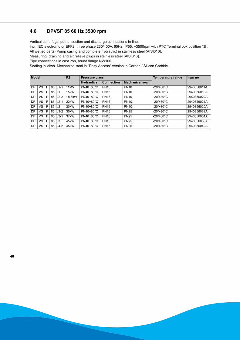
4.6 DPVSF 85 60 Hz 3500 rpm
Vertical centrifugal pump, suction and discharge connections in-line.Incl. IEC electromotor EFF2, three phase 230/400V, 60Hz, IP55, ~3500rpm with PTC Terminal box position "3h.All wetted parts (Pump casing and complete hydraulic) in stainless steel (AISI316).Measuring, draining and air relieve plugs in stainless steel (AISI316).Pipe connections in cast iron, round flange NW100.Sealing in Viton. Mechanical seal in "Easy Access" version in Carbon / Silicon Carbide.
Model P2 Pressure class Temperature range Item noHydraulics Connection Mechanical seal
DP VS F 85 /1-1 11kW PN40+80°C PN16 PN10 -20/+80°C 2940856011ADP VS F 85 /1 15kW PN40+80°C PN16 PN10 -20/+80°C 2940856010ADP VS F 85 /2-2 18.5kW PN40+80°C PN16 PN10 -20/+80°C 2940856022ADP VS F 85 /2-1 22kW PN40+80°C PN16 PN10 -20/+80°C 2940856021ADP VS F 85 /2 30kW PN40+80°C PN16 PN10 -20/+80°C 2940856020ADP VS F 85 /3-2 30kW PN40+80°C PN16 PN25 -20/+80°C 2940856032ADP VS F 85 /3-1 37kW PN40+80°C PN16 PN25 -20/+80°C 2940856031ADP VS F 85 /3 45kW PN40+80°C PN16 PN25 -20/+80°C 2940856030ADP VS F 85 /4-2 45kW PN40+80°C PN16 PN25 -20/+80°C 2940856042A
41
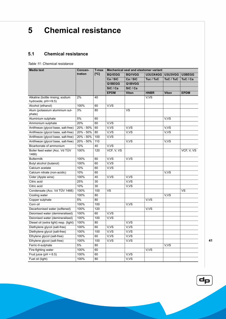
5 Chemical resistance
5.1 Chemical resistance
Table 11: Chemical resistance
Media text Concen-tration
T-max[ºC]
Mechanical seal and elastomer variantBQ1EGG BQ1VGG U3U3X4GG U3U3VGG U3BEGGCa / SiC Ca / SiC Tuc / TuC TuC / TuC TuC / CaQ1BEGG Q1BVGGSiC / Ca SiC / CaEPDM Viton HNBR Viton EPDM
Alkaline (bottle rinsing; sodium hydroxide; pH<=9.5)
2% 40 V,VS
Alcohol (ethanol) 100% 60 V,VSAlum (potassium aluminium sul-phate)
3% 80 VS
Aluminium sulphate 5% 60 V,VSAmmonium sulphate 20% 60 V,VSAntifreeze (glycol base, salt-free) 20% - 50% 60 V,VS V,VS V,VSAntifreeze (glycol base, salt-free) 20% - 50% 80 V,VS V,VS V,VSAntifreeze (glycol base, salt-free) 20% - 50% 100 V,VSAntifreeze (glycol base, salt-free) 20% - 50% 110 V,VS V,VSBicarbonate of ammonium 10% 40 V,VSBoiler feed water (Acc. Vd TÜV 1466)
100% 120 VCF, V, VS VCF, V, VS
Buttermilk 100% 60 V,VS V,VSButyl alcohol (butanol) 100% 60 V,VSCalcium acetate 10% 60 V,VSCalcium nitrate (non-acidic) 10% 60 V,VSCider (Apple wine) 100% 40 V,VS V,VSCitric acid 25% 30 V,VSCitric acid 10% 30 V,VSCondensate (Acc. Vd TÜV 1466) 100% 100 VS VSCooling water 100% 80 V,VSCopper sulphate 5% 80 V,VSCorn oil 100% 100 V,VSDecarbonised water (softened) 100% 120 V,VSDeionised water (demineralised) 100% 60 V,VSDeionised water (demineralised) 100% 100 V,VSDiesel oil (extra light) resp. (light) 100% 80 V,VSDiethylene glycol (salt-free) 100% 60 V,VS V,VSDiethylene glycol (salt-free) 100% 100 V,VS V,VSEthylene glycol (salt-free) 100% 60 V,VS V,VSEthylene glycol (salt-free) 100% 100 V,VS V,VSFerric-II-sulphate 5% 80 V,VSFire-fighting water 100% 60 V,VSFruit juice (pH = 6.5) 100% 60 V,VSFuel oil (light) 100% 80 V,VS
42
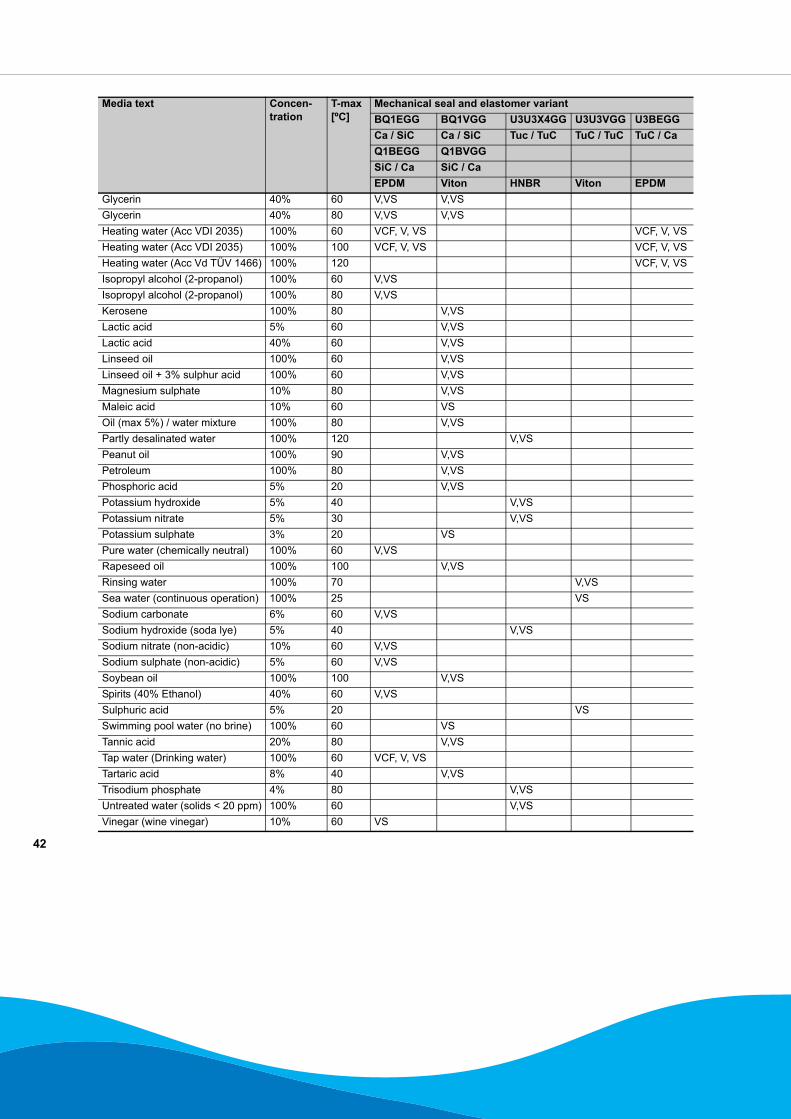
Glycerin 40% 60 V,VS V,VSGlycerin 40% 80 V,VS V,VSHeating water (Acc VDI 2035) 100% 60 VCF, V, VS VCF, V, VSHeating water (Acc VDI 2035) 100% 100 VCF, V, VS VCF, V, VSHeating water (Acc Vd TÜV 1466) 100% 120 VCF, V, VSIsopropyl alcohol (2-propanol) 100% 60 V,VSIsopropyl alcohol (2-propanol) 100% 80 V,VSKerosene 100% 80 V,VSLactic acid 5% 60 V,VSLactic acid 40% 60 V,VSLinseed oil 100% 60 V,VSLinseed oil + 3% sulphur acid 100% 60 V,VSMagnesium sulphate 10% 80 V,VSMaleic acid 10% 60 VSOil (max 5%) / water mixture 100% 80 V,VSPartly desalinated water 100% 120 V,VSPeanut oil 100% 90 V,VSPetroleum 100% 80 V,VSPhosphoric acid 5% 20 V,VSPotassium hydroxide 5% 40 V,VSPotassium nitrate 5% 30 V,VSPotassium sulphate 3% 20 VSPure water (chemically neutral) 100% 60 V,VSRapeseed oil 100% 100 V,VSRinsing water 100% 70 V,VSSea water (continuous operation) 100% 25 VSSodium carbonate 6% 60 V,VSSodium hydroxide (soda lye) 5% 40 V,VSSodium nitrate (non-acidic) 10% 60 V,VSSodium sulphate (non-acidic) 5% 60 V,VSSoybean oil 100% 100 V,VSSpirits (40% Ethanol) 40% 60 V,VSSulphuric acid 5% 20 VSSwimming pool water (no brine) 100% 60 VSTannic acid 20% 80 V,VSTap water (Drinking water) 100% 60 VCF, V, VSTartaric acid 8% 40 V,VSTrisodium phosphate 4% 80 V,VSUntreated water (solids < 20 ppm) 100% 60 V,VSVinegar (wine vinegar) 10% 60 VS
Media text Concen-tration
T-max[ºC]
Mechanical seal and elastomer variantBQ1EGG BQ1VGG U3U3X4GG U3U3VGG U3BEGGCa / SiC Ca / SiC Tuc / TuC TuC / TuC TuC / CaQ1BEGG Q1BVGGSiC / Ca SiC / CaEPDM Viton HNBR Viton EPDM

43
dp pumps
dp pumpsP.O. Box 282400 AA Alphen aan den RijnThe Netherlands
t +31 172 48 83 25f +31 172 46 89 30
09/2008
97004442
Subject to modifications without prior notice


![Resilient Wind Turbine Design · 2019-04-03 · Frequency [Hz] f R . f R + 7 Hz f R - 7 Hz . 100 . Voltage [% of nominal] 80 85 . 120 . Normal continuous operation . max. 60s . 145](https://img.pdfslide.us/doc/110x75/5f08b3537e708231d4234c90/resilient-wind-turbine-design-2019-04-03-frequency-hz-f-r-f-r-7-hz-f-r-.jpg)

![Dynamic Programming [1ex] DPV Chapter 6, Part 1 · Dynamic Programming DPV Chapter 6, Part 1 Jim Royer March 6, 2019 Dynamic Programming 1/19](https://img.pdfslide.us/doc/110x75/5fffb3e0584dc36f0c57cb84/dynamic-programming-1ex-dpv-chapter-6-part-1-dynamic-programming-dpv-chapter.jpg)