Embed Size (px)
Citation preview

TECH TIP
75K or 150K MILES BURNER MAINTENANCE SUBJECT VEHICLES: 11MY-14MY Conventional with burner system
OVERVIEW: For trucks equipped with the burner system, certain environmental and unit
applications have been found to cause unreliable operation of the system. Collected
technical data indicates that decreasing the maintenance intervals can greatly improve
system reliability. High idle, time, constant exhaust brake operation, stop and go traffic and
PTO operation can be factors that reduce reliability. A general burner system cleaning and
inspection are being recommended at 75K miles and the 150K service interval will stay the
same. Two parts kits have been developed to include all the necessary parts for the 150K
service and the added 75K service if it is determined that parts replacement is needed.
Note: This technical tip is provided as technical information and is not authorization for a
warrantable repair.
PARTS:
75K KIT PART# HN001234045
150K KIT PART# HN001234044
Group: 0-GENERAL
Engine Bulletin No: TT-15-030
Issue Date: 10-13-2015
Part Numbers Part Description Quantity
19200E0030 Igniter Assembly Ceramic 2
23602E0010 Nozzle Assembly – Burner Fuel 1
Part Numbers Part Description Quantity
19200E0030 Igniter Assembly Ceramic 2
23602E0010 Nozzle Assembly – Burner Fuel 1
89429E0030 Sensor-Exh Temp/Flame Thermo 1
FS1994290 Fuel Filter Burner (11-14MY) 1

VEHICLE PREPARATION
1. Park the vehicle on a flat, level and solid surface.
2. Confirm the engine is stopped, the ignition switch is in the off (LOCK) position, and the key is removed.
3. Apply the parking brake.
4. Chock all of the wheels.
TECH TIP
Group: 0-GENERAL
Bulletin No: SB-15-031
Issue Date: 10-13-2015

TECH TIP
MAINTENANCE PROCEDURE
1. Remove the right inner fender. Make certain the A/C drain hose is removed, located on the
engine side of the right fender.
Remove one (1) nut and six (6) bolts (shown in the illustration to the right) that secure the right
front fender. Remove the right front fender from the vehicle.
Group: 0-GENERAL
Engine Bulletin No: TT-15-030
Issue Date: 10-13-2015

TECH TIP
2. Locate the forward face of the combustor and disconnect the ignition wires from both
ceramic igniter plugs.
Notice: When disconnecting the ignition wires, securely grasp the center of the ignition wire
boot to prevent shifting of the electrical terminal and wire position within the boot.
Group: 0-GENERAL
Engine Bulletin No: TT-15-030
Issue Date: 10-13-2015

TECH TIP
3. Remove the steel braided fuel/air supply line, nozzle and copper washer.
Note: Over 150K miles, replace the nozzle.
(75K Only)
4.Clean the outside and inside of the nozzle with brake cleaner.
CAUTION: Do not wipe the outside of the nozzle; otherwise, the nozzle may become
clogged. If the nozzle is clogged or cannot produce a consistent spray pattern, it is
recommended to replace.
Group: 0-GENERAL
Engine Bulletin No: TT-15-030
Issue Date: 10-13-2015

TECH TIP
Notice: During igniter plug removal, care should be taken to prevent any debris from entering the ignition wire boots or the combustion chamber.
5. Remove both the igniter plugs, for 75K miles, carefully clean them with brake cleaner and a wire brush. Reinstall both igniter plugs and torque to the specified torque.
Note: Over 150K miles, replace the igniters and go to Step 8.
Specified Torque: 22.0 lb-ft (29.8 Nm)
Using the SST, check the igniter plug gap:
The SST is a “Go - No-Go” gauge to check the igniter at the tips. The tool has a 2.5mm gauge on one end and a 3.5mm gauge on the other end. The 2.5mm end should be able to pass between the igniter tips while the 3.5mm end should not.
Does the igniter gap fall within the specification?
• If Yes – Go to Step 10.
• If No – Go to Step 6.
Specification: 2.5mm – 3.5mm
Group: 0-GENERAL
Engine Bulletin No: TT-15-030
Issue Date: 10-13-2015

TECH TIP
6. Remove both blue ceramic igniter plugs from the combustor.
7. Switch igniter positions from side to side. Reinstall both igniter plugs and torque to the
specified torque.
Specified Torque: 22.0 lb-ft (29.8 Nm)
Group: 0-GENERAL
Engine Bulletin No: TT-15-030
Issue Date: 10-13-2015

TECH TIP
8. Using the SST, does the igniter gap fall within the specification?
• If Yes – Go to Step 10.
• If No – Go to Step 9.
NOTE: If you can’t get the igniter gap within the specification, it is recommended that the
igniters are replaced.
9. Remove one (1) igniter from the combustor and exchange it with another new one. Due to
manufacturing variability of igniters it may be necessary to replace one of the two igniters to
bring the gap within specification.
Install the replacement igniter into the combustor then torque to the specified torque. Confirm
the igniter gap meets the specification, then go to to Step 10. Retain the removed igniter
plug for use in another vehicle.
Notice: Do not forget to apply the Silkon 1000 dielectric grease to the igniter plug terminal.
Failure to apply Silkon 1000 dielectric grease may cause electric corrosion on the igniter
terminal during operation. Electrical corrosion on the igniter terminal may result in a burner
system misfire.
10. Apply a small amount of Silkon 1000 dielectric grease on each blue ceramic igniter plug
terminal.
Group: 0-GENERAL
Engine Bulletin No: TT-15-030
Issue Date: 10-13-2015

TECH TIP
11. Install and electrically connect each ignition wire onto the corresponding blue ceramic
igniter plug.
Notice: Failure to install the ignition wire boot to meet the installed specification may result in a
burner system misfire.
12. Check the exposed ceramic surface of each igniter plug. If not within the installed
specification, adjust the ignition wire boot to meet the installed specification.
Installed Specification: 0.28 inch (7mm) or less .
Group: 0-GENERAL
Engine Bulletin No: TT-15-030
Issue Date: 10-13-2015
TECH TIP
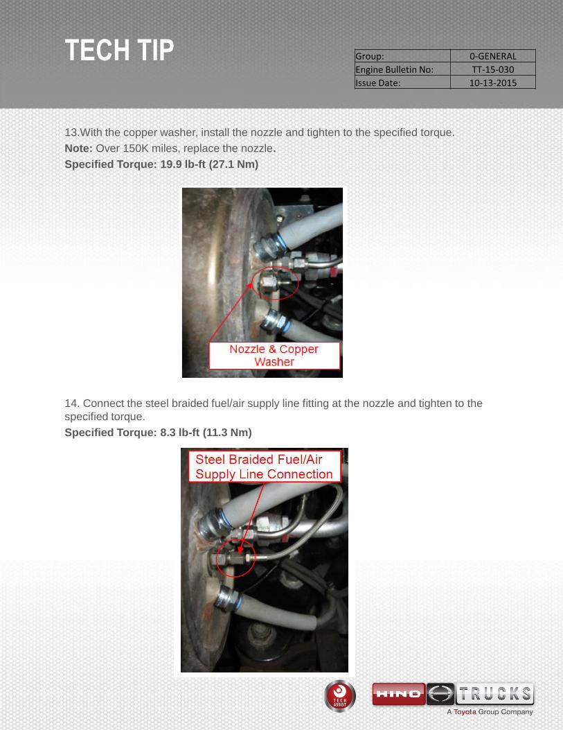
13.With the copper washer, install the nozzle and tighten to the specified torque.
Note: Over 150K miles, replace the nozzle.
Specified Torque: 19.9 lb-ft (27.1 Nm)
14. Connect the steel braided fuel/air supply line fitting at the nozzle and tighten to the
specified torque.
Specified Torque: 8.3 lb-ft (11.3 Nm)
Group: 0-GENERAL
Engine Bulletin No: TT-15-030
Issue Date: 10-13-2015

TECH TIP
Notice: After removal, avoid entry of foreign matter into the hose or combustor.
15. Disconnect the combustion air hose from the combustor and check the orifice. Carefully,
clean the orifice with brake cleaner and a wire brush.
16. Connect the combustion air hose to the combustor.
150K Trucks Only
17. Replace the flame temperature sensor.
18. Replace the burner fuel filter. Refer to the workshop manual for burner fuel filter
replacement.
Group: 0-GENERAL
Engine Bulletin No: TT-15-030
Issue Date: 10-13-2015

TECH TIP
75K and 150K Trucks
19. Install the right front fender and secure using one (1) nut and six (6) bolts (shown in the
illustration to the right). Tighten each fastener to the specified torque value.
Specified Torque:
Nut: 9.6 lb-ft (13.0 Nm)
Bolt: 10.4 lb-ft (14.0 Nm)
20. Make certain the A/C drain hose is secured by the clamp located on the engine side of the
right fender.
Group: 0-GENERAL
Engine Bulletin No: TT-15-030
Issue Date: 10-13-2015

TECH TIP
21.Perform a manual regeneration and check for soot in the tailpipe. If soot is found in the
tailpipe, a physical DPF inspection must be done.
150K Trucks Only
22. Reset the burner maintenance light.
a. Select “Diagnosis” on the left side of the screen, select “600 Series” and “North America”
from the drop down boxes. Place a check next to the “Engine” selection and select “Read Out”.
Group: 0-GENERAL
Engine Bulletin No: TT-15-030
Issue Date: 10-13-2015

TECH TIP
b. Select the “Data Monitor and Active Test” tab and select “Active Test Setting”.
c. Check the “Burner Maintenance Distance Reset” and select “Select”.
d. Select “Start” and complete the burner maintenance reset.
Group: 0-GENERAL
Engine Bulletin No: TT-15-030
Issue Date: 10-13-2015