Embed Size (px)
Citation preview
1
Date: 07/01/2006
Update of the Technical Proposal for the Design, Construction, Commissioning and Operation
of the EXL Project (Exotic nuclei studied in light-ion induced reactions at the NESR storage ring)
The EXL Collaboration
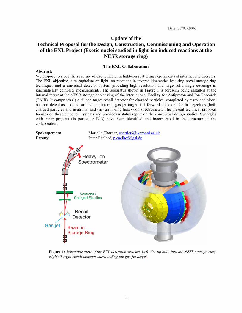
Abstract: We propose to study the structure of exotic nuclei in light-ion scattering experiments at intermediate energies. The EXL objective is to capitalise on light-ion reactions in inverse kinematics by using novel storage-ring techniques and a universal detector system providing high resolution and large solid angle coverage in kinematically complete measurements. The apparatus shown in Figure 1 is foreseen being installed at the internal target at the NESR storage-cooler ring of the international Facility for Antiproton and Ion Research (FAIR). It comprises (i) a silicon target-recoil detector for charged particles, completed by γ-ray and slow-neutron detectors, located around the internal gas-jet target, (ii) forward detectors for fast ejectiles (both charged particles and neutrons) and (iii) an in-ring heavy-ion spectrometer. The present technical proposal focuses on these detection systems and provides a status report on the conceptual design studies. Synergies with other projects (in particular R3B) have been identified and incorporated in the structure of the collaboration. Spokesperson: Marielle Chartier, [email protected] Deputy: Peter Egelhof, [email protected]
RecoilDetectorRecoil
Detector
Neutrons /Charged Ejectiles
Neutrons /Charged Ejectiles
Gas jetGas jet Beam inStorage RingBeam inStorage Ring
Heavy-IonSpectrometer
Heavy-IonSpectrometer
RecoilDetector
Figure 1: Schematic view of the EXL detection systems. Left: Set-up built into the NESR storage ring. Right: Target-recoil detector surrounding the gas-jet target.
2
Members of the EXL Collaboration: Basel, Switzerland, Universität Basel (Basel) K. Hencken, J. Jourdan, B. Krusche, T. Rauscher, D. Rohe, F. Thielemann Birmingham, United Kingdom, University of Birmingham (U.K.) M. Freer Daresbury, United Kingdom, CLRC Daresbury Laboratory (U.K.) P. Coleman-Smith, I. Lazarus, R. Lemmon, S.Letts, V. Pucknell Darmstadt, Germany, Gesellschaft für Schwerionenforschung (GSI) T. Aumann, F. Becker, K. Beckert, P. Beller, K. Boretzky, A. Dolinski, P. Egelhof, H. Emling, H. Feldmeier, B. Franczak, H. Geissel, J. Gerl, C. Kozhuharov, Y. Litvinov, J.P. Meier, T. Neff, F. Nolden, C. Peschke, U. Popp, H. Reich-Sprenger, H. Simon, M. Steck, T. Stöhlker, K.Sümmerer, S. Typel, H. Weick, M. Winkler Darmstadt, Germany, Technische Universität Darmstadt (TUD) T. Nilsson, G. Schrieder Debrecen, Hungary, Institute of Nuclear Research (ATOMKI) A. Algora, M. Csátlos, Z. Gáski, J. Gulyás, M. Hunyadi, A. Krasznahorkay Dubna, Russia, FLNR Joint Institute of Nuclear Research (Dubna) A.G. Artukh, S.A. Klygin, G.A. Kononenko, Yu.M. Sereda, E.A. Shevchik, Yu.G. Teterev, A.N. Vorontzov Frankfurt, Germany, Institut für Kernphysik, Universität Frankfurt (Frankfurt) R. Dörner, R. Grisenti, J. Stroth Gatchina, Russia, St. Petersburg Nuclear Physics Institute and St. Petersburg State University (PNPI) V. Ivanov, A. Khanzadeev, E. Rostchin, O. Tarasenkova, Y. Zalite Göteborg, Sweden, Chalmers Institute (Chalmers) B. Jonson, T. Nilsson, G. Nyman Groningen, KVI, The Netherlands (KVI) M.N. Harakeh, N. Kalantar-Nayestanaki, H. Wörtche Guildford, United Kingdom, University of Surrey (U.K.) J. Al-Khalili, W. Catford, R. Johnson, P. Stevenson, I. Thompson Heslington, United Kingdom, University of York (U.K.) C. Barton, B. Fulton, D. Jenkins, A. Laird Jülich, Germany, Institut für Kernphysik, Forschungszentrum Jülich (FZJ) D. Grzonka, T. Krings, D. Protic, F. Rathmann Kolkata, India, Saha Institute of Nuclear Physics (Kolkata) S. Bhattacharya, U. Datta Pramanik Liverpool, United Kingdom, University of Liverpool (U.K.) M. Chartier, J. Cresswell, B. Fernandez Dominguez, J. Thornhill Lund, Sweden, Lund University (Lund) V. Avdeichikov, L. Carlén, P. Gobulev, B. Jakobsson
3
Madrid, Spain, CSIC, Instituto de Estructura de la Materia (CSIC) E. Garrido, O. Moreno, P. Sarriguren, J. R. Vignote Madrid, Spain, Universidad Complutense (U.C. Madrid) L. Fraile, J. López Herraiz, E. Moya de Guerra, J.M. Udias, C. Martínez-Pérez Mainz, Germany, Johannes Gutenberg Universität (Mainz) O. Kiselev, J.V. Kratz Milan, Italy, Universitá da Milano and INFN (Milano) A. Bracco, P.F. Bortignon, G. Coló, A. Zalite Moscow, Russia, Russian Research Centre, Kurchatov Institute (Kurchatov) L. Chulkov Mumbai, India, Bhabha Atomic Research Center (BARC) S. Kailas, A. Shrivastava Munich, Germany, Technische Universität München (TUM) M. Böhmer, T. Faestermann, R. Gernhäuser, P. Kienle, R. Krücken, L. Maier, K. Suzuki Orsay, France, Institut de Physique Nucléaire (IPNO) D. Beaumel, Y. Blumenfeld, E. Khan, J. Peyre, J. Pouthas, J.A. Scarpaci, F. Skaza, T. Zerguerras Osaka, Japan, Osaka University (Osaka) Y. Fujita Saclay, France, CEA/DAPNIA (CEA) F. Auger, A. Drouart, A. Gillibert, L. Nalpas St. Petersburg, Russia, V.G. Khlopin Radium Institute (St. Petersburg) Y. Murin São Paulo, Brasil, Universidade de São Paulo (São Paulo) A. Lépine-Szily Sundsvall, Sweden, Mid Sweden University (Sundsvall) G. Thungström Tehran, Iran, University of Tehran (Tehran) M. Mahjour-Shafiei Uppsala, Sweden, The Svedberg Laboratory (TSL) C. Ekström, L. Westerberg Vancouver, Canada, TRIUMF (TRIUMF) R. Kanungo Spokesperson:
Name: M. Chartier E-Mail: [email protected] Telephone Number: +44 (0)151 794 6775
Deputy Spokesperson / GSI Liaison:
Name: P. Egelhof E-Mail: [email protected] Telephone Number: +49 (0)6159 71 2662

4
Table of Contents A Introduction and Overview 1 Overview 2 Physics case
2.1 Elastic scattering 2.2 Inelastic scattering and giant resonances 2.3 Charge-exchange reactions 2.4 Transfer reactions 2.5 Quasi-free scattering
3 Timeliness, originality and complementarities 4 Experimental requirements B Systems 1 Experimental set-up
1.1 Preparation and performance of stored radioactive beams 1.2 Internal target and vacuum system 1.3 Luminosity monitor 1.4 Target recoil, γ-ray and slow-neutron detectors 1.5 Forward detector for fast ejectiles 1.6 In-ring heavy-ion spectrometer
2 Trigger, DAQ, controls, on-line/off-line computing 2.1 Trigger 2.2 DAQ 2.3 Slow control
3 Summary of beam/target requirements 3.1 Beam specifications 3.2 Running scenario
4 Physics performance C Implementation and Installation 1 Cave and annex facilities 2 Detector-machine interface 3 Assembly and installation D Commissioning E Operation F Safety G Organisation and Responsibilities, Planning 1 Organisation of the collaboration, tasks and responsibilities 2 Contributions of the participating institutes H Relation to other Projects I Annex: The NUSTAR data acquisition concept J References
5
A Introduction and Overview 1 Overview Light-hadron scattering has provided a wealth of nuclear structure information for stable nuclei. Usually, such reactions are performed in ‘normal kinematics’, i.e. where intermediate-energy light ions are scattered from a fixed target consisting of stable nuclei. Secondary beams of exotic nuclei produced by in-flight fragmentation of primary heavy-ion beams can be scattered from stable light target nuclei using the so-called ‘inverse kinematics’. Because of luminosity constraints and the specific circumstances of inverse kinematics, these scattering experiments could not be applied to a similar extent as the normal kinematics scattering experiments. Up to present, such investigations are restricted to light exotic nuclei and only with limited applications even there. A wide and unique discovery potential would emerge if such reactions can be studied using exotic nuclei far from the valley of stability. Using inverse kinematics on light stable target nuclei, essential contributions can be made to most important nuclear structure and nuclear astrophysics issues discussed in the context of exotic nuclei, in particular for neutron-rich nuclei, towards which the current thrust is being directed. Here, we just name a few interesting topics:
• The unusual matter distributions in neutron-rich nuclei near the neutron drip line, exhibiting neutron halos and skins;
• The shell structure in nuclei of extreme proton-to-neutron asymmetry leading to a disappearance of the known magic numbers and, in turn, to the appearance of new shell gaps;
• Deformations different for the proton and neutron distributions giving rise, as a consequence, to new collective modes;
• Electric and magnetic giant resonances with strength distributions totally different from those known in stable nuclei;
• In-medium interactions in proton-neutron asymmetric and low-density nuclear matter. Light-hadron scattering in the intermediate-to-high energy regime (here, typically bombarding energies of 100 – 700 MeV/nucleon are considered) is a well-established method in nuclear-structure physics; its application to beams of exotic nuclei is indispensable. The great nuclear structure potential of light-hadron scattering arises from the fact that, by means of a proper choice of the probe, transitions can selectively be induced (e.g. emphasising or excluding spin and/or isospin transitions), and the form factors are sensitive to the transition multipolarity. Polarised targets allow to be selective not only on the orbital angular momentum, l, but also on the total angular momentum, j, and therefore give extra sensitivity on the spin-orbit part of the potential. The physics case and the preliminary experimental scheme were already outlined in the EXL Letter of Intent as part of the NUSTAR project at the future FAIR international facility. Below, we elaborate on the physics case and research objectives. The subsequent chapters of the present proposal are focusing on the detection systems. A conceptual design is provided where the principal specifications are addressed and the technical solutions are discussed. Detailed solutions will be worked out over a period of the next year. Therein, allowance is made for a possible evolution in developments, in particular, in the area of detection media and configurations where rapid advances are expected.
6
2 Physics case
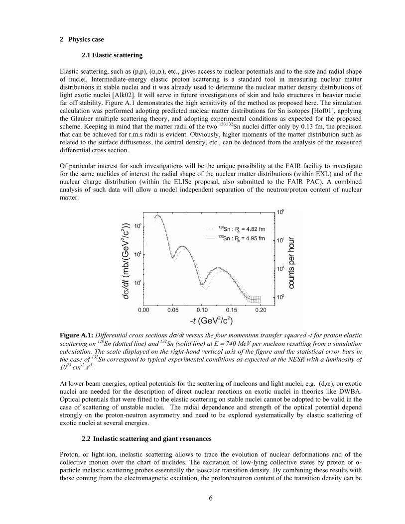
2.1 Elastic scattering Elastic scattering, such as (p,p), (α,α), etc., gives access to nuclear potentials and to the size and radial shape of nuclei. Intermediate-energy elastic proton scattering is a standard tool in measuring nuclear matter distributions in stable nuclei and it was already used to determine the nuclear matter density distributions of light exotic nuclei [Alk02]. It will serve in future investigations of skin and halo structures in heavier nuclei far off stability. Figure A.1 demonstrates the high sensitivity of the method as proposed here. The simulation calculation was performed adopting predicted nuclear matter distributions for Sn isotopes [Hof01], applying the Glauber multiple scattering theory, and adopting experimental conditions as expected for the proposed scheme. Keeping in mind that the matter radii of the two 120,132Sn nuclei differ only by 0.13 fm, the precision that can be achieved for r.m.s radii is evident. Obviously, higher moments of the matter distribution such as related to the surface diffuseness, the central density, etc., can be deduced from the analysis of the measured differential cross section. Of particular interest for such investigations will be the unique possibility at the FAIR facility to investigate for the same nuclides of interest the radial shape of the nuclear matter distributions (within EXL) and of the nuclear charge distribution (within the ELISe proposal, also submitted to the FAIR PAC). A combined analysis of such data will allow a model independent separation of the neutron/proton content of nuclear matter.
Figure A.1: Differential cross sections dσ/dt versus the four momentum transfer squared -t for proton elastic scattering on 120Sn (dotted line) and 132Sn (solid line) at E = 740 MeV per nucleon resulting from a simulation calculation. The scale displayed on the right-hand vertical axis of the figure and the statistical error bars in the case of 132Sn correspond to typical experimental conditions as expected at the NESR with a luminosity of 1028 cm-2 s-1. At lower beam energies, optical potentials for the scattering of nucleons and light nuclei, e.g. (d,α), on exotic nuclei are needed for the description of direct nuclear reactions on exotic nuclei in theories like DWBA. Optical potentials that were fitted to the elastic scattering on stable nuclei cannot be adopted to be valid in the case of scattering of unstable nuclei. The radial dependence and strength of the optical potential depend strongly on the proton-neutron asymmetry and need to be explored systematically by elastic scattering of exotic nuclei at several energies.
2.2 Inelastic scattering and giant resonances Proton, or light-ion, inelastic scattering allows to trace the evolution of nuclear deformations and of the collective motion over the chart of nuclides. The excitation of low-lying collective states by proton or α-particle inelastic scattering probes essentially the isoscalar transition density. By combining these results with those coming from the electromagnetic excitation, the proton/neutron content of the transition density can be
7
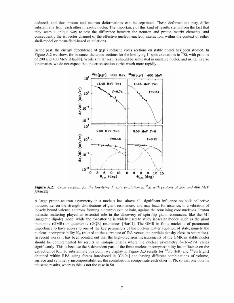
deduced, and thus proton and neutron deformations can be separated. These deformations may differ substantially from each other in exotic nuclei. The importance of this kind of results stems from the fact that they seem a unique way to test the difference between the neutron and proton matrix elements, and consequently the isovector channel of the effective nucleon-nucleon interaction, within the context of either shell-model or mean-field-based calculations. In the past, the energy dependence of (p,p’) inelastic cross sections on stable nuclei has been studied. In Figure A.2 we show, for instance, the cross sections for the low-lying 1+ spin excitations in 28Si, with protons of 200 and 400 MeV [Häu88]. While similar results should be simulated in unstable nuclei, and using inverse kinematics, we do not expect that the cross section varies much more rapidly.
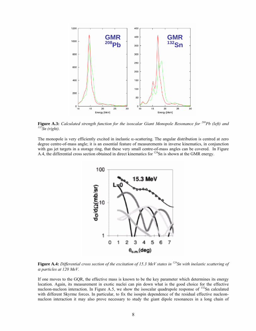
Figure A.2: Cross sections for the low-lying 1+ spin excitation in 28Si with protons at 200 and 400 MeV [Häu88]. A large proton-neutron asymmetry in a nucleus has, above all, significant influence on bulk collective motions, i.e. on the strength distributions of giant resonances, and may lead, for instance, to a vibration of loosely bound valence neutrons forming a neutron skin or halo, against the remaining core nucleons. Proton inelastic scattering played an essential role in the discovery of spin-flip giant resonances, like the M1 (magnetic dipole) mode, while the α-scattering is widely used to study isoscalar modes, such as the giant monopole (GMR) or quadrupole (GQR) resonances [Har01]. The GMR in finite nuclei is of paramount importance to have access to one of the key parameters of the nuclear matter equation of state, namely the nuclear incompressibility K∞ (related to the curvature of E/A versus the particle density close to saturation). In recent works it has been pointed out that the high-precision measurements of the GMR in stable nuclei should be complemented by results in isotopic chains where the nuclear asymmetry δ=(N−Z)/A varies significantly. This is because the δ-dependent part of the finite nucleus incompressibility has influence on the extraction of K∞. To substantiate this point, we display in Figure A.3 results for 208Pb (left) and 132Sn (right) obtained within RPA using forces introduced in [Col04] and having different combinations of volume, surface and symmetry incompressibilities: the contributions compensate each other in Pb, so that one obtains the same results, whereas this is not the case in Sn.
8
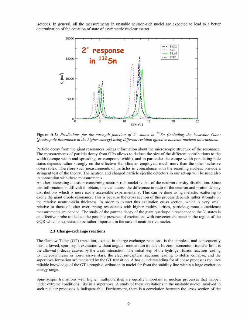
Figure A.3: Calculated strength function for the isoscalar Giant Monopole Resonance for 208Pb (left) and 132Sn (right). The monopole is very efficiently excited in inelastic α-scattering. The angular distribution is centred at zero degree centre-of-mass angle; it is an essential feature of measurements in inverse kinematics, in conjunction with gas jet targets in a storage ring, that these very small centre-of-mass angles can be covered. In Figure A.4, the differential cross section obtained in direct kinematics for 124Sn is shown at the GMR energy.
Figure A.4: Differential cross section of the excitation of 15.3 MeV states in 124Sn with inelastic scattering of α particles at 120 MeV. If one moves to the GQR, the effective mass is known to be the key parameter which determines its energy location. Again, its measurement in exotic nuclei can pin down what is the good choice for the effective nucleon-nucleon interaction. In Figure A.5, we show the isoscalar quadrupole response of 132Sn calculated with different Skyrme forces. In particular, to fix the isospin dependence of the residual effective nucleon-nucleon interaction it may also prove necessary to study the giant dipole resonances in a long chain of
GMR 208Pb
GMR 132Sn
9
isotopes. In general, all the measurements in unstable neutron-rich nuclei are expected to lead to a better determination of the equation of state of asymmetric nuclear matter.
Figure A.5: Predictions for the strength function of 2+ states in 132Sn (including the isoscalar Giant Quadrupole Resonance at the higher energy) using different residual effective nucleon-nucleon interactions. Particle decay from the giant resonances brings information about the microscopic structure of the resonance. The measurements of particle decay from GRs allows to deduce the size of the different contributions to the width (escape width and spreading, or compound width), and in particular the escape width populating hole states depends rather strongly on the effective Hamiltonian employed, much more than the other inclusive observables. Therefore such measurements of particles in coincidence with the recoiling nucleus provide a stringent test of the theory. The neutron and charged particle ejectile detectors in our set-up will be used also in connection with these measurements. Another interesting question concerning neutron-rich nuclei is that of the neutron density distribution. Since this information is difficult to obtain, one can access the difference in radii of the neutron and proton density distributions which is more easily accessible experimentally. This can be done using inelastic scattering to excite the giant dipole resonance. This is because the cross section of this process depends rather strongly on the relative neutron-skin thickness. In order to extract this excitation cross section, which is very small relative to those of other overlapping resonances with higher multipolarities, particle-gamma coincidence measurements are needed. The study of the gamma decay of the giant quadrupole resonance to the 3− states is an effective probe to deduce the possible presence of excitations with isovector character in the region of the GQR which is expected to be rather important in the case of neutron-rich nuclei.
2.3 Charge-exchange reactions The Gamow-Teller (GT) transition, excited in charge-exchange reactions, is the simplest, and consequently most allowed, spin-isopin excitation without angular momentum transfer. Its zero momentum-transfer limit is the allowed β-decay caused by the weak interaction. The initial step of the hydrogen fusion reaction leading to nucleosynthesis in non-massive stars, the electron-capture reactions leading to stellar collapse, and the supernova formation are mediated by the GT transition. A basic understanding for all these processes requires reliable knowledge of the GT strength distribution in nuclei far from the stability line within a large excitation energy range. Spin-isospin transitions with higher multipolarities are equally important in nuclear processes that happen under extreme conditions, like in a supernova. A study of these excitations in the unstable nuclei involved in such nuclear processes is indispensable. Furthermore, there is a correlation between the cross section of the
2+ response in 132Sn
10
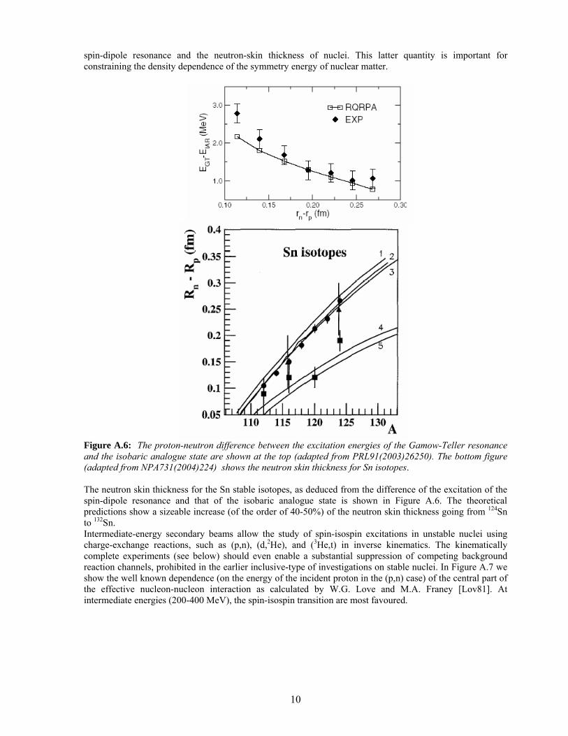
spin-dipole resonance and the neutron-skin thickness of nuclei. This latter quantity is important for constraining the density dependence of the symmetry energy of nuclear matter.
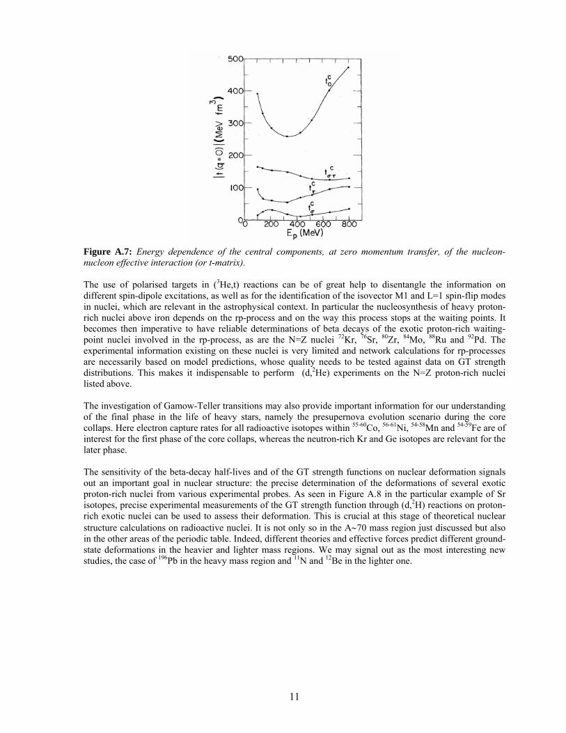
Figure A.6: The proton-neutron difference between the excitation energies of the Gamow-Teller resonance and the isobaric analogue state are shown at the top (adapted from PRL91(2003)26250). The bottom figure (adapted from NPA731(2004)224) shows the neutron skin thickness for Sn isotopes. The neutron skin thickness for the Sn stable isotopes, as deduced from the difference of the excitation of the spin-dipole resonance and that of the isobaric analogue state is shown in Figure A.6. The theoretical predictions show a sizeable increase (of the order of 40-50%) of the neutron skin thickness going from 124Sn to 132Sn. Intermediate-energy secondary beams allow the study of spin-isospin excitations in unstable nuclei using charge-exchange reactions, such as (p,n), (d,2He), and (3He,t) in inverse kinematics. The kinematically complete experiments (see below) should even enable a substantial suppression of competing background reaction channels, prohibited in the earlier inclusive-type of investigations on stable nuclei. In Figure A.7 we show the well known dependence (on the energy of the incident proton in the (p,n) case) of the central part of the effective nucleon-nucleon interaction as calculated by W.G. Love and M.A. Franey [Lov81]. At intermediate energies (200-400 MeV), the spin-isospin transition are most favoured.
11
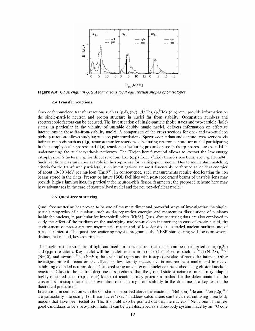
Figure A.7: Energy dependence of the central components, at zero momentum transfer, of the nucleon-nucleon effective interaction (or t-matrix). The use of polarised targets in (3He,t) reactions can be of great help to disentangle the information on different spin-dipole excitations, as well as for the identification of the isovector M1 and L=1 spin-flip modes in nuclei, which are relevant in the astrophysical context. In particular the nucleosynthesis of heavy proton-rich nuclei above iron depends on the rp-process and on the way this process stops at the waiting points. It becomes then imperative to have reliable determinations of beta decays of the exotic proton-rich waiting-point nuclei involved in the rp-process, as are the N=Z nuclei 72Kr, 76Sr, 80Zr, 84Mo, 88Ru and 92Pd. The experimental information existing on these nuclei is very limited and network calculations for rp-processes are necessarily based on model predictions, whose quality needs to be tested against data on GT strength distributions. This makes it indispensable to perform (d,2He) experiments on the N=Z proton-rich nuclei listed above. The investigation of Gamow-Teller transitions may also provide important information for our understanding of the final phase in the life of heavy stars, namely the presupernova evolution scenario during the core collaps. Here electron capture rates for all radioactive isotopes within 55-60Co, 56-61Ni, 54-58Mn and 54-59Fe are of interest for the first phase of the core collaps, whereas the neutron-rich Kr and Ge isotopes are relevant for the later phase. The sensitivity of the beta-decay half-lives and of the GT strength functions on nuclear deformation signals out an important goal in nuclear structure: the precise determination of the deformations of several exotic proton-rich nuclei from various experimental probes. As seen in Figure A.8 in the particular example of Sr isotopes, precise experimental measurements of the GT strength function through (d,2H) reactions on proton-rich exotic nuclei can be used to assess their deformation. This is crucial at this stage of theoretical nuclear structure calculations on radioactive nuclei. It is not only so in the A∼70 mass region just discussed but also in the other areas of the periodic table. Indeed, different theories and effective forces predict different ground-state deformations in the heavier and lighter mass regions. We may signal out as the most interesting new studies, the case of 196Pb in the heavy mass region and 11N and 12Be in the lighter one.
12
Figure A.8: GT strength in QRPA for various local equilibrium shapes of Sr isotopes.
2.4 Transfer reactions One- or few-nucleon transfer reactions such as (p,d), (p,t), (d,3He), (p,3He), (d,p), etc., provide information on the single-particle neutron and proton structure in nuclei far from stability. Occupation numbers and spectroscopic factors can be deduced. The investigation of single-particle (hole) states and two-particle (hole) states, in particular in the vicinity of unstable doubly magic nuclei, delivers information on effective interactions in these far-from-stability nuclei. A comparison of the cross sections for one- and two-nucleon pick-up reactions allows studying nucleon pair correlations. Spectroscopic data and capture cross sections via indirect methods such as (d,p) neutron transfer reactions substituting neutron capture for nuclei participating in the astrophysical r-process and (d,n) reactions substituting proton capture in the rp-process are essential in understanding the nucleosynthesis pathways. The 'Trojan-horse' method allows to extract the low-energy astrophysical S factors, e.g. for direct reactions like (α,p) from (6Li,d) transfer reactions, see e.g. [Tum04]. Such reactions play an important role in the rp-process for waiting-point nuclei. Due to momentum matching criteria for the transferred particle(s), such investigations are most favourably performed at incident energies of about 10-30 MeV per nucleon [Ege97]. In consequence, such measurements require decelerating the ion beams stored in the rings. Present or future ISOL facilities with post-accelerated beams of unstable ions may provide higher luminosities, in particular for neutron-rich fission fragments; the proposed scheme here may have advantages in the case of shorter-lived nuclei and for neutron-deficient nuclei.
2.5 Quasi-free scattering Quasi-free scattering has proven to be one of the most direct and powerful ways of investigating the single-particle properties of a nucleus, such as the separation energies and momentum distributions of nucleons inside the nucleus, in particular for inner-shell orbits [Kit85]. Quasi-free scattering data are also employed to study the effect of the medium on the underlying nucleon-nucleon interaction; in case of exotic nuclei, the environment of proton-neutron asymmetric matter and of low density in extended nuclear surfaces are of particular interest. The quasi-free scattering physics program at the NESR storage ring will focus on several distinct, but related, key experiments. The single-particle structure of light and medium-mass neutron-rich nuclei can be investigated using (p,2p) and (p,pn) reactions. Key nuclei will be nuclei near neutron (sub-)shell closures such as 56Ni (N=28), 68Ni (N=40), and towards 78Ni (N=50); the chains of argon and tin isotopes are also of particular interest. Other investigations will focus on the effects in low-density matter, i.e. in neutron halo nuclei and in nuclei exhibiting extended neutron skins. Clustered structures in exotic nuclei can be studied using cluster knockout reactions. Close to the neutron drip line it is predicted that the ground-state structure of nuclei may adopt a highly clustered state. (p,p-cluster) knockout reactions may provide a method for the determination of the cluster spectroscopic factor. The evolution of clustering from stability to the drip line is a key test of the theoretical predictions. In addition, in connection with the GT studies described above the reactions 12Be(p,pn)11Be and 17Ne(p,2p)16F are particularly interesting. For these nuclei ‘exact’ Faddeev calculations can be carried out using three body models that have been tested on 6He. It should also be pointed out that the nucleus 17Ne is one of the few good candidates to be a two-proton halo. It can be well described as a three-body system made by an 15O core
13
and two protons. This is a Borromean system (none of the two-body subsystem is bound), and the excited states (three-body resonances) are promising candidates to decay through direct two-proton emission. An accurate knowledge of the structure of this nucleus is then desirable. A system like 12Be is different compared to the previous case. This is not a Borromean system (11Be is bound), and has excited bound states. Although a description of the nucleus as a three-body system (10Be+n+n) is in principle possible, other structures (molecular type) are also suggested (α+α+4n). The possibility that some of the bound excited states exhibit a neutron halo structure is also under investigation and the (p,2p) and (p,pn) reactions will be essential tools. For sufficiently high energy the sudden approximation basically applies, and the importance of the reaction mechanism decreases with increasing beam energy. The information about nuclear structure can be more easily extracted. As an example, the narrow neutron momentum after fragmentation of 6He is a clean indication of the halo structure of this nucleus.
14
3 Timeliness, originality and complementarities Until now and presently, a number of experimental attempts were and are undertaken at various laboratories to perform light-hadron scattering with rare-isotope beams. Proton elastic and inelastic scattering, knockout and transfer reactions at low-to-intermediate energies have been performed at GANIL (France), GSI (Germany), JINR (Russia), MSU (USA) and RIKEN (Japan). Elastic scattering experiments have been used for matter radii and distribution measurements of light halo nuclei such as 6,8He or 11Li, inelastic scattering experiments provided data on the excitation of bound excited states. Heavy-ion induced knockout reactions have been used to measure spectroscopic factors. In contrast to quasi-free proton scattering, such knockout reactions probe, however, only the asymptotic part of the (valence) nucleon wave function. As far as giant resonances in exotic nuclei are concerned, the present-day technique relies on heavy-ion induced Coulomb excitation, which is restricted, however, to the nuclear dipole response. Light-hadron scattering, together with electron scattering, the standard tools in that respect, could not yet be used. So far, light-ion scattering measurements were performed for light unstable nuclei only and were of more inclusive type. For heavy exotic nuclei, measurements at low momentum transfer require a different experimental technique. The originality of the present project arises, in essence, from the following aspects:
• The project represents, worldwide, a first attempt to implement nuclear reaction studies with unstable exotic nuclei utilising heavy-ion storage rings. Windowless thin internal targets are a key prerequisite for studies at low momentum transfer.
• The detector system under consideration (see below) is universal in the sense that it allows to handle a wide class of different nuclear reactions and thus to address numerous physics questions. Technologically, the required Ultra-High-Vacuum compatibility is most demanding and requires non-standard solutions of the detector design.
• The detector system provides the capability of fully exclusive kinematical measurements. This is of interest not only in experiments with exotic nuclei, but also with stable beams. Conventional techniques in the context of light-hadron scattering are of inclusive type to a large extent.
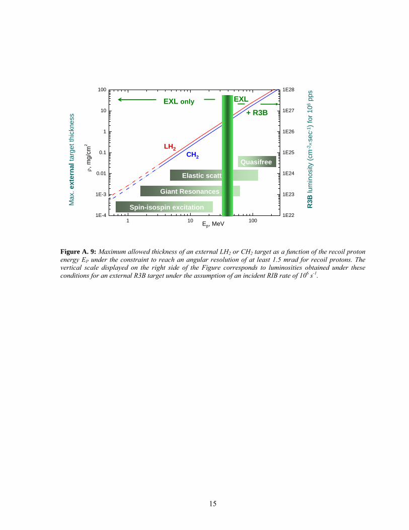
The EXL physics program has some overlap with that proposed in the R3B project as far as light-ion scattering is considered there; while R3B will cover the part of large momentum transfer, EXL will exclusively be able to measure at low momentum transfer, but also at high momentum transfer. This is illustrated in Figure A. 9, where the maximum allowed thickness of an external target as a function of the recoil proton energy EP is plotted under the constraint to reach sufficient angular resolution (at least 1.5 mrad) for the recoil protons. It is obvious from this Figure that with external LH2 or CH2 targets the luminosities at R3B (a RIB rate of 106 s-1 is assumed for this example) will drop down considerably for EP ≤ 30 MeV, and even more, below EP ≈ 5 MeV solid or liquid external targets with the required thickness are not available. In contrast, for the case of an internal target a luminosity of ≥ 1028 cm-2s-1 will be reached for the comparable production rate (nuclear lifetimes ≥ 1 s assumed) for the whole range of recoil proton energies. Therefore for many cases of high physics interest (see section 2) cross section measurement with sufficient statistical accuracy will be possible exclusively with EXL. Only for nuclear lifetimes much below one second, where beam cooling (see section B.1.1) is not fast enough, measurements at the external target (R3B) are of preference. The particular physics case addressed with the active target concept within the R3B project has some clear overlap with that of the EXL project, but the two different projects are actually complementary. The EXL project will allow to reach high luminosities for all cases where the nuclear lifetime of the exotic ions is sufficiently long (> 500 ms) to allow for beam preparation in the CR/NESR rings and for continuous accumulation and stacking. Keeping in mind that the rate capability of the active target technique will be limited, especially for very heavy projectiles, to about 105 s–1 or less, luminosities of the order of 1028 cm–2 s–1, as expected for EXL, will not be reachable with external active targets. On the other hand there are many cases of exotic beams of high interest for nuclear structure and nuclear astrophysics, which are located far outside the valley of stability, and consequently have half-lives much shorter than 500 ms, and relatively low production rates, well below 105 s –1. For such cases the technique of active targets, as presented in the R3B Technical Proposal, is currently considered as the only way to perform high-resolution experiments at low momentum transfer for a number of reactions with sufficiently high cross sections.
15
EXL
+ R3B
Giant Resonances
Elastic scatt.
1 10 1001E-4
1E-3
0.01
0.1
1
10
100
1E22
1E23
1E24
1E25
1E26
1E27
1E28
CH2 target liH2 target
ρ,
mg/
cm2
Ep, MeV
Lum
inos
ity, s
-1
LH2CH2
Max
. ext
erna
ltar
get t
hick
ness
Spin-isospin excitation
Quasifree
EXL only
Ep, MeV
R3B
lum
inos
ity (c
m-2
×sec
-1) f
or 1
06pp
s
Figure A. 9: Maximum allowed thickness of an external LH2 or CH2 target as a function of the recoil proton energy EP under the constraint to reach an angular resolution of at least 1.5 mrad for recoil protons. The vertical scale displayed on the right side of the Figure corresponds to luminosities obtained under these conditions for an external R3B target under the assumption of an incident RIB rate of 106 s-1.
16
4 Experimental requirements For the studies discussed above, exotic nuclei are provided as a secondary beam to be scattered off the light target nuclei (e.g. p, d, 3He, 4He). For a number of studies, e.g. that of the GMR or GT strength, the relevant nuclear structure information is obtained from form factors measured at rather moderate or even small momentum transfer, i.e. at c.m. angles around zero degree. Inverse kinematics implies that the light target nuclei emerge from the reaction with extraordinarily low kinetic energies, below 1 MeV. Momentum and energy transfer need to be extracted from the kinematical quantities of the light target recoil, because of the high projectile energy and because of the fact that the heavy projectile-like fragment often disintegrates. In order to extract reliable information on excitation energy (required resolution 0.1-1 MeV) and on centre-of-mass scattering angle (required resolution: a few mrad), kinetic energy and scattering angle of the target recoil in the laboratory frame need to be measured with a resolution of the order of 100 keV and 1 mrad, respectively (see section B.1.4 for details). Additional mandatory prerequisites are a) a small spread in kinetic energy (Tb) of the secondary ion beams (δTb/Tb ~ 10-3) and b) a low target thickness in order to let the target recoils escape and to keep small-angle multiple scattering on a tolerable level (typically, the effective target thickness, including windows, needs to be below 1 mg/cm2). Low target thickness yields low reaction luminosities; transferring the beam into a storage ring and thus benefiting from beam accumulation and re-circulation can overcome this problem. The CR-RESR-NESR storage-ring complex planned at the Facility for Antiproton and Ion Research (FAIR) provides optimal conditions for inverse light-ion scattering experiments, the most relevant features are:
• Luminosities above 1028 cm-2 s-1 can be achieved; further developments on internal targets may even yield improved values. Cross sections of 0.1 – 100 mb/sr are typical for reactions and thus very reasonable reaction rates are expected. The windowless internal target avoids background reactions.
• Stochastic pre-cooling in the CR combined with electron cooling in the NESR provides stored beams of excellent quality with regard to emittance and momentum spread, matching the requirements (see above) for kinematical measurements of the target recoils.
• The energy of the stored beam is variable within a wide range up to 740 (depending on magnetic rigidity even up to 820) MeV per nucleon. For nuclei with a lifetime of at least seconds deceleration down to tens of MeV per nucleon becomes feasible without substantial deterioration of beam intensity and quality. This wide range in beam energy suits well the experimental programme under discussion.
• Secondary beams produced in fragmentation or fission reactions may have sizeable contaminants of nuclei in long-lived isomeric states. Measuring during distinct time intervals after injection into the ring allows disentangling such beam components (an interesting scheme of separating isomeric beams by a beam-scraping technique is proposed in the ILIMA proposal submitted to the FAIR PAC).
The main objectives of the experimental scheme as proposed in this Technical Proposal are:
• To optimise the luminosity, • To provide a high-resolution detection system with nearly full solid-angle coverage and
detection efficiency, • To provide a detector set-up for kinematically complete measurements, thus covering
simultaneously all reaction channels of interest. The subsequent chapters provide a status report on the EXL technical design.
17
B Systems The experimental apparatus consists of a number of sub-systems described in this chapter:
• The beam of unstable nuclei is prepared in the FAIR storage-ring complex (section B.1.1). • An internal gas-jet target is installed at the NESR (section B.1.2). • A detection system monitors the target-beam luminosity (section B.1.3). • A detector of high granularity built around the target measures recoil nuclei and γ-rays (section
B.1.4). It is composed out of Si-strip, Si(Li), and CsI arrays, optionally including a scintillator array for low-energy neutrons.
• Charged particles and neutrons emitted from the projectile are detected in the forward direction (section B.1.5).
• A heavy-ion spectrometer identifies the projectile fragments (section B.1.6). Integrated read-out electronics is presented alongside with the detector units; trigger, data acquisition, and slow control are discussed in sections B.2.1-3 and I (Annex). The detector system will be implemented in two phases. Phase II will complement Phase I with the target detector part covering the backward hemisphere around the target, essentially required for nuclear reactions with decelerated beams, and with an upgrade of the forward neutron detector. 1 Experimental setup
1.1 Preparation and performance of stored radioactive beams Secondary beams are transferred from the fragment separator (Super-FRS) to the collector ring (CR) at a fixed energy of 740 MeV/nucleon. The main task of the CR is the efficient collection and stochastic pre-cooling to a relative momentum spread around 10-4 and an emittance of 1 mm mrad within a cooling time of below one second. The beam quality can be further improved by means of electron cooling in the new experimental storage ring (NESR). Electron cooling serves as well to compensate the beam heating due to its interaction with the internal target. Using RF cavities inside the RESR, a third storage ring in between the CR and NESR, the beam can be decelerated thus providing a variable energy (RF cavities are also installed at the NESR). Luminosity at the internal target is increased with increasing circulating frequency (~ 1 MHz) of the stored beam. An important option to achieve optimum luminosity is fast beam stacking. The limitation for this scheme is given by the beam lifetime that is determined by the nuclear lifetime and losses due to atomic charge exchange processes in the internal target, in the residual gas in the ring, and in the electron cooler. Some representative examples are given in Table B.1, Figure B.1 gives an overview on the achievable luminosities over the whole chart of nuclides. Multi-charge state operation of the NESR may increase the effective beam lifetime and thus luminosity. Below, we expand on details of the operation of the storage ring complex to the extent being essential for the EXL project; otherwise, we refer to the Technical Design Report (Jan. 2005) on FAIR accelerators and to the Accelerator Part of this Technical Report. Operation of storage rings The experiment starts with creating a pure beam of a single nuclide. This can be achieved with the Super-FRS and in addition by means of the mass-to-charge selectivity of the CR, see [CDR01,Nol00]. Isotopic impurities, in principle, can evolve during beam circulation in the ring due to nuclear reactions in the target or the residual gas or due to nuclear decays. Ions with different mass and charge, however, are detected and thus removed as described later. Only in case of bound-state beta decay they cannot be discriminated as it leads to the same mass number and charge; but this decay mode is relevant only for a few isotopes close to stability. Fast cooling in the CR is important for the investigation of short-lived nuclides. An envisaged reduction of the longitudinal momentum spread down to around ∆p/p=2x10-4 and a transverse emittance of 0.5 mm mrad within 0.5 s is sufficient for most EXL experiments. This means that the measurement can start directly after injection into the NESR. Under this condition, a continuous accumulation of the fragment beam in the NESR can be performed using longitudinal stacking. With the help of RF a barrier bucket is created that moves the ions out of one section of the ring. This free space can than be filled by a new injection; afterwards the two bunches are merged again. Electron cooling compensates the emittance growth during this process. For the
18
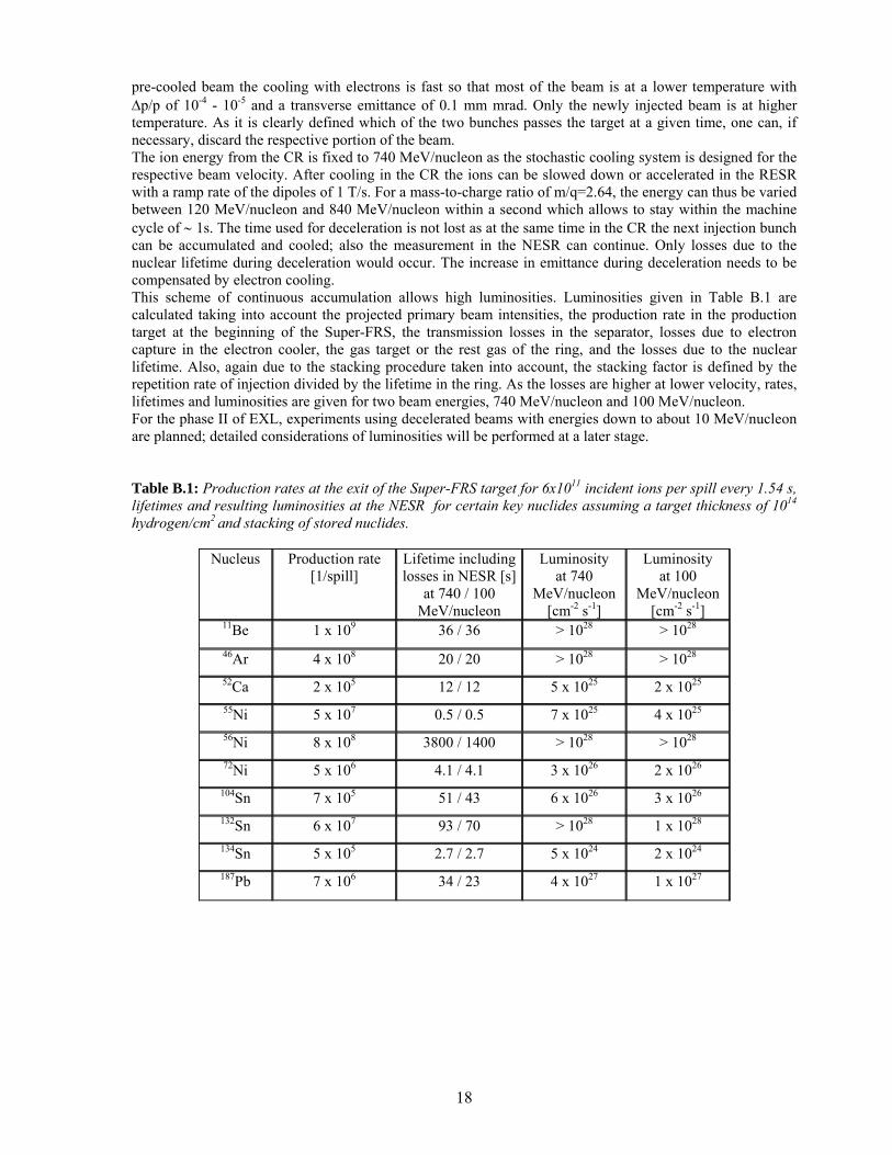
pre-cooled beam the cooling with electrons is fast so that most of the beam is at a lower temperature with ∆p/p of 10-4 - 10-5 and a transverse emittance of 0.1 mm mrad. Only the newly injected beam is at higher temperature. As it is clearly defined which of the two bunches passes the target at a given time, one can, if necessary, discard the respective portion of the beam. The ion energy from the CR is fixed to 740 MeV/nucleon as the stochastic cooling system is designed for the respective beam velocity. After cooling in the CR the ions can be slowed down or accelerated in the RESR with a ramp rate of the dipoles of 1 T/s. For a mass-to-charge ratio of m/q=2.64, the energy can thus be varied between 120 MeV/nucleon and 840 MeV/nucleon within a second which allows to stay within the machine cycle of ∼ 1s. The time used for deceleration is not lost as at the same time in the CR the next injection bunch can be accumulated and cooled; also the measurement in the NESR can continue. Only losses due to the nuclear lifetime during deceleration would occur. The increase in emittance during deceleration needs to be compensated by electron cooling. This scheme of continuous accumulation allows high luminosities. Luminosities given in Table B.1 are calculated taking into account the projected primary beam intensities, the production rate in the production target at the beginning of the Super-FRS, the transmission losses in the separator, losses due to electron capture in the electron cooler, the gas target or the rest gas of the ring, and the losses due to the nuclear lifetime. Also, again due to the stacking procedure taken into account, the stacking factor is defined by the repetition rate of injection divided by the lifetime in the ring. As the losses are higher at lower velocity, rates, lifetimes and luminosities are given for two beam energies, 740 MeV/nucleon and 100 MeV/nucleon. For the phase II of EXL, experiments using decelerated beams with energies down to about 10 MeV/nucleon are planned; detailed considerations of luminosities will be performed at a later stage. Table B.1: Production rates at the exit of the Super-FRS target for 6x10¹¹ incident ions per spill every 1.54 s, lifetimes and resulting luminosities at the NESR for certain key nuclides assuming a target thickness of 1014
hydrogen/cm2 and stacking of stored nuclides.
Nucleus Production rate [1/spill]
Lifetime including losses in NESR [s]
at 740 / 100 MeV/nucleon
Luminosity at 740
MeV/nucleon [cm-2 s-1]
Luminosity at 100
MeV/nucleon [cm-2 s-1]
11Be 1 x 10⁹ 36 / 36 > 1028 > 1028 46Ar 4 x 10⁸ 20 / 20 > 1028 > 1028 52Ca 2 x 10⁵ 12 / 12 5 x 1025 2 x 1025 55Ni 5 x 10⁷ 0.5 / 0.5 7 x 1025 4 x 1025 56Ni 8 x 10⁸ 3800 / 1400 > 1028 > 1028 72Ni 5 x 10⁶ 4.1 / 4.1 3 x 1026 2 x 1026
104Sn 7 x 10⁵ 51 / 43 6 x 1026 3 x 1026 132Sn 6 x 10⁷ 93 / 70 > 1028 1 x 1028 134Sn 5 x 10⁵ 2.7 / 2.7 5 x 1024 2 x 1024 187Pb 7 x 10⁶ 34 / 23 4 x 1027 1 x 1027
19
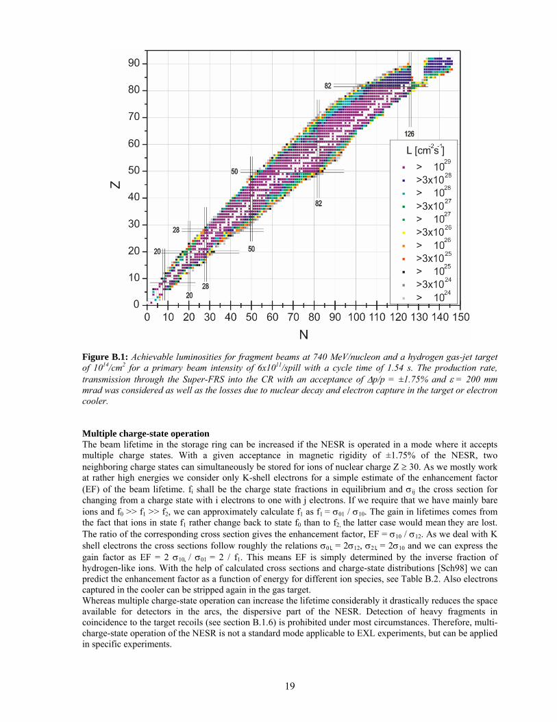
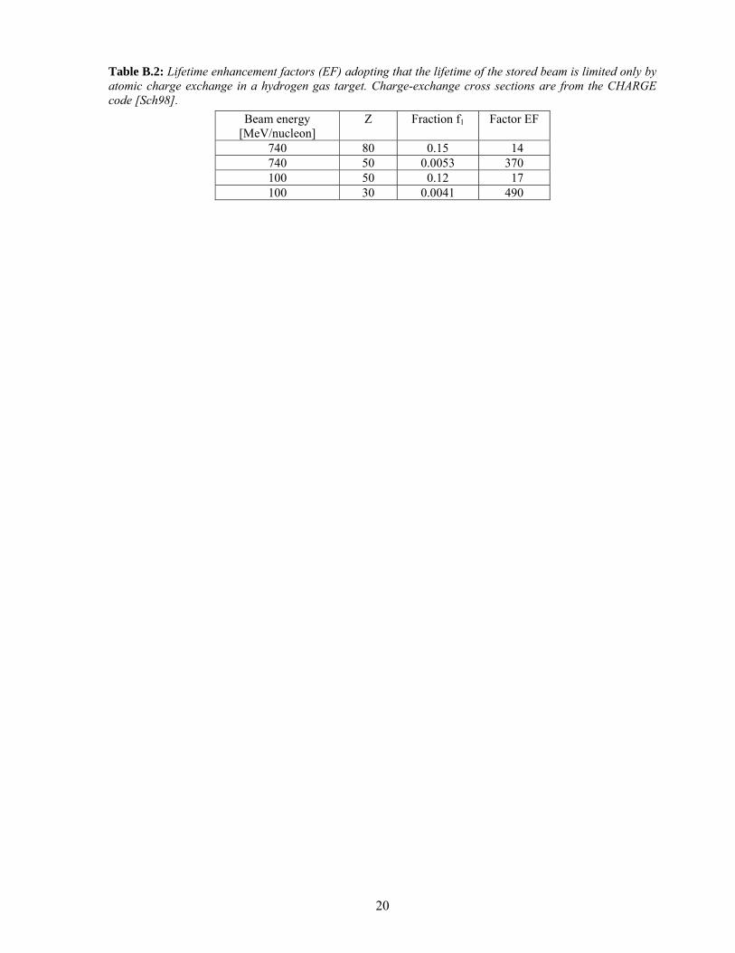
Figure B.1: Achievable luminosities for fragment beams at 740 MeV/nucleon and a hydrogen gas-jet target of 1014/cm2 for a primary beam intensity of 6x10¹¹/spill with a cycle time of 1.54 s. The production rate, transmission through the Super-FRS into the CR with an acceptance of ∆p/p = ±1.75% and ε = 200 mm mrad was considered as well as the losses due to nuclear decay and electron capture in the target or electron cooler. Multiple charge-state operation The beam lifetime in the storage ring can be increased if the NESR is operated in a mode where it accepts multiple charge states. With a given acceptance in magnetic rigidity of ±1.75% of the NESR, two neighboring charge states can simultaneously be stored for ions of nuclear charge Z ≥ 30. As we mostly work at rather high energies we consider only K-shell electrons for a simple estimate of the enhancement factor (EF) of the beam lifetime. fi shall be the charge state fractions in equilibrium and σij the cross section for changing from a charge state with i electrons to one with j electrons. If we require that we have mainly bare ions and f0 >> f1 >> f2, we can approximately calculate f1 as f1 = σ01 / σ10. The gain in lifetimes comes from the fact that ions in state f1 rather change back to state f0 than to f2, the latter case would mean they are lost. The ratio of the corresponding cross section gives the enhancement factor, EF = σ10 / σ12. As we deal with K shell electrons the cross sections follow roughly the relations σ01 = 2σ12, σ21 = 2σ10 and we can express the gain factor as EF = 2 σ10 / σ01 = 2 / f1. This means EF is simply determined by the inverse fraction of hydrogen-like ions. With the help of calculated cross sections and charge-state distributions [Sch98] we can predict the enhancement factor as a function of energy for different ion species, see Table B.2. Also electrons captured in the cooler can be stripped again in the gas target. Whereas multiple charge-state operation can increase the lifetime considerably it drastically reduces the space available for detectors in the arcs, the dispersive part of the NESR. Detection of heavy fragments in coincidence to the target recoils (see section B.1.6) is prohibited under most circumstances. Therefore, multi-charge-state operation of the NESR is not a standard mode applicable to EXL experiments, but can be applied in specific experiments.
20
Table B.2: Lifetime enhancement factors (EF) adopting that the lifetime of the stored beam is limited only by atomic charge exchange in a hydrogen gas target. Charge-exchange cross sections are from the CHARGE code [Sch98].
Beam energy [MeV/nucleon]
Z Fraction f1 Factor EF
740 80 0.15 14 740 50 0.0053 370 100 50 0.12 17 100 30 0.0041 490
21
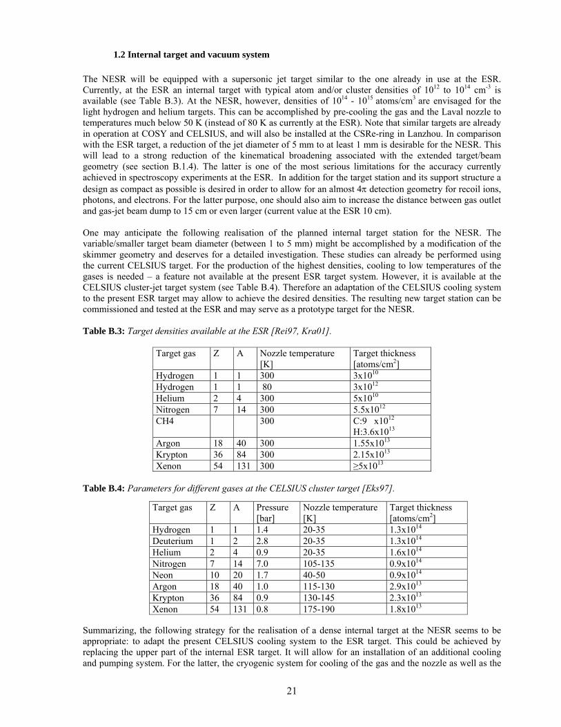
1.2 Internal target and vacuum system The NESR will be equipped with a supersonic jet target similar to the one already in use at the ESR. Currently, at the ESR an internal target with typical atom and/or cluster densities of 1012 to 1014 cm-3 is available (see Table B.3). At the NESR, however, densities of 1014 - 1015 atoms/cm3 are envisaged for the light hydrogen and helium targets. This can be accomplished by pre-cooling the gas and the Laval nozzle to temperatures much below 50 K (instead of 80 K as currently at the ESR). Note that similar targets are already in operation at COSY and CELSIUS, and will also be installed at the CSRe-ring in Lanzhou. In comparison with the ESR target, a reduction of the jet diameter of 5 mm to at least 1 mm is desirable for the NESR. This will lead to a strong reduction of the kinematical broadening associated with the extended target/beam geometry (see section B.1.4). The latter is one of the most serious limitations for the accuracy currently achieved in spectroscopy experiments at the ESR. In addition for the target station and its support structure a design as compact as possible is desired in order to allow for an almost 4π detection geometry for recoil ions, photons, and electrons. For the latter purpose, one should also aim to increase the distance between gas outlet and gas-jet beam dump to 15 cm or even larger (current value at the ESR 10 cm). One may anticipate the following realisation of the planned internal target station for the NESR. The variable/smaller target beam diameter (between 1 to 5 mm) might be accomplished by a modification of the skimmer geometry and deserves for a detailed investigation. These studies can already be performed using the current CELSIUS target. For the production of the highest densities, cooling to low temperatures of the gases is needed – a feature not available at the present ESR target system. However, it is available at the CELSIUS cluster-jet target system (see Table B.4). Therefore an adaptation of the CELSIUS cooling system to the present ESR target may allow to achieve the desired densities. The resulting new target station can be commissioned and tested at the ESR and may serve as a prototype target for the NESR. Table B.3: Target densities available at the ESR [Rei97, Kra01].
Target gas Z A Nozzle temperature [K]
Target thickness [atoms/cm2]
Hydrogen 1 1 300 3x10¹⁰ Hydrogen 1 1 80 3x10¹² Helium 2 4 300 5x10¹⁰ Nitrogen 7 14 300 5.5x10¹² CH4 300 C:9 x10¹²
H:3.6x10¹³
Argon 18 40 300 1.55x10¹³ Krypton 36 84 300 2.15x10¹³ Xenon 54 131 300 ≥5x10¹³
Table B.4: Parameters for different gases at the CELSIUS cluster target [Eks97]. Summarizing, the following strategy for the realisation of a dense internal target at the NESR seems to be appropriate: to adapt the present CELSIUS cooling system to the ESR target. This could be achieved by replacing the upper part of the internal ESR target. It will allow for an installation of an additional cooling and pumping system. For the latter, the cryogenic system for cooling of the gas and the nozzle as well as the
Target gas Z A Pressure [bar]
Nozzle temperature [K]
Target thickness [atoms/cm2]
Hydrogen 1 1 1.4 20-35 1.3x10¹⁴ Deuterium 1 2 2.8 20-35 1.3x10¹⁴ Helium 2 4 0.9 20-35 1.6x10¹⁴ Nitrogen 7 14 7.0 105-135 0.9x10¹⁴ Neon 10 20 1.7 40-50 0.9x10¹⁴ Argon 18 40 1.0 115-130 2.9x10¹³ Krypton 36 84 0.9 130-145 2.3x10¹³ Xenon 54 131 0.8 175-190 1.8x10¹³
22
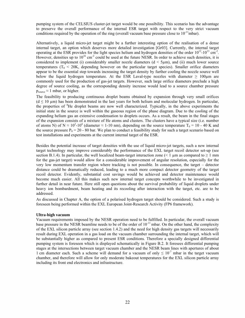
pumping system of the CELSIUS cluster-jet target would be one possibility. This scenario has the advantage to preserve the overall performance of the internal ESR target with respect to the very strict vacuum conditions required by the operation of the ring (overall vacuum base pressure close to 10-11mbar). Alternatively, a liquid micro-jet target might be a further interesting option of the realisation of a dense internal target, an option which deserves more detailed investigation [Gr03]. Currently, the internal target operating at the ESR provides for the light species helium and hydrogen densities of the order 1012-1013 cm-2. However, densities up to 1016 cm-2 could be used at the future NESR. In order to achieve such densities, it is considered to implement (i) considerably smaller nozzle diameters (d < 5µm), and (ii) much lower source temperatures (T0 < 20K, depending however on the particular target species). Smaller orifice diameters appear to be the essential step towards increasing the target density by further cooling the nozzle source well below the liquid hydrogen temperature. At the ESR Laval-type nozzles with diameter ≥ 100µm are commonly used for the production of gas-jet targets. However, such large orifice diameters preclude a high degree of source cooling, as the corresponding density increase would lead to a source chamber pressure psource ≈ 1 mbar, or higher. The feasibility to producing continuous droplet beams obtained by expansion through very small orifices (d ≤ 10 µm) has been demonstrated in the last years for both helium and molecular hydrogen. In particular, the properties of 4He droplet beams are now well characterized. Typically, in the above experiments the initial state in the source is well within the gaseous region of the phase diagram. Due to the cooling of the expanding helium gas an extensive condensation to droplets occurs. As a result, the beam in the final stages of the expansion consists of a mixture of He atoms and clusters. The clusters have a typical size (i.e. number of atoms N) of N ≈ 102-104 (diameter ≈ 1-10 nm), depending on the source temperature T0 = 10 - 40 K and the source pressure P0 = 20 - 80 bar. We plan to conduct a feasibility study for such a target scenario based on test installations and experiments at the current internal target of the ESR. Besides the potential increase of target densities with the use of liquid micro-jet targets, such a new internal target technology may improve considerably the performance of the EXL target recoil detector set-up (see section B.1.4). In particular, the well localized beam-target interaction zone (< 1 µm as compared to ≥ 1 mm for the gas-jet target) would allow for a considerable improvement of angular resolution, especially for the very low momentum transfer region where tracking is not possible. In consequence, the target – detector distance could be dramatically reduced, leading to a much more compact detector geometry of the target recoil detector. Evidently, substantial cost savings would be achieved and detector maintenance would become much easier. All this makes such new internal target concepts worthwhile to be investigated in further detail in near future. Here still open questions about the survival probability of liquid droplets under heavy ion bombardment, beam heating and its recooling after interaction with the target, etc. are to be addressed. As discussed in Chapter A, the option of a polarised hydrogen target should be considered. Such a study is foreseen being performed within the EXL European Joint-Research Activity (FP6 framework). Ultra-high vacuum Vacuum requirements imposed by the NESR operation need to be fulfilled. In particular, the overall vacuum base pressure in the NESR beamline needs to be of the order of 10-11 mbar. On the other hand, the complexity of the EXL silicon particle array (see section 1.4.2) and the need for high density gas targets will necessarily result during EXL operation in a gas load on the vacuum chamber surrounding the internal target, which will be substantially higher as compared to present ESR conditions. Therefore a specially designed differential pumping system is foreseen which is displayed schematically in Figure B.2. It foresees differential pumping stages at the intersections between target vacuum chamber and the NESR beam lines with apertures of about 1 cm diameter each. Such a scheme will demand for a vacuum of only ≤ 10-7 mbar in the target vacuum chamber, and therefore will allow for only moderate bakeout temperatures for the EXL silicon particle array including its front end electronics and infrastructure.
23
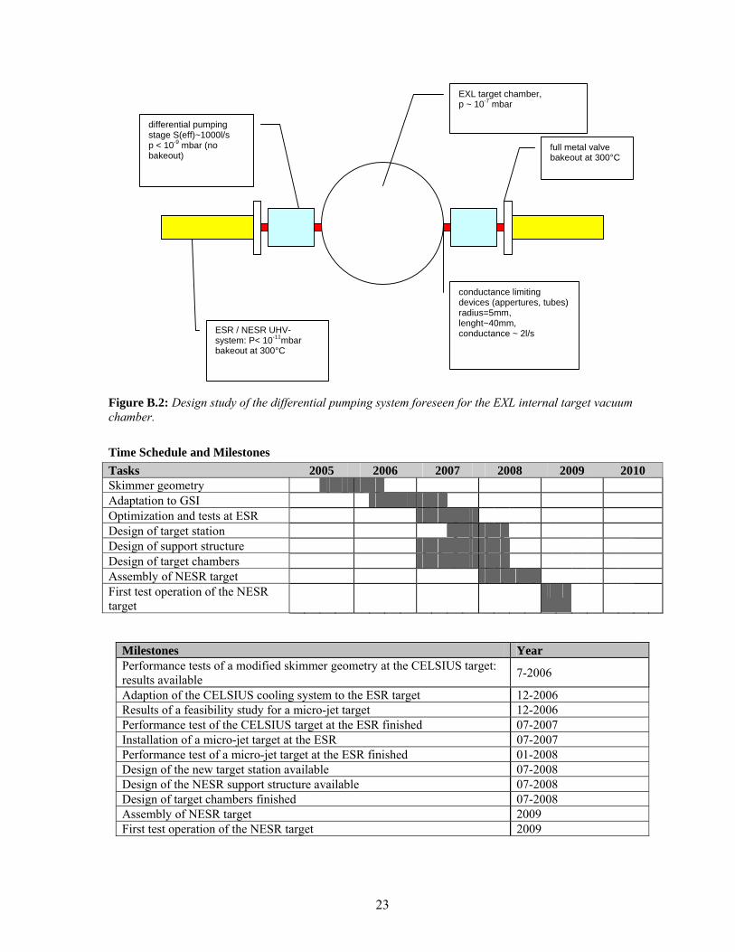
Figure B.2: Design study of the differential pumping system foreseen for the EXL internal target vacuum chamber. Time Schedule and Milestones Tasks 2005 2006 2007 2008 2009 2010 Skimmer geometry Adaptation to GSI Optimization and tests at ESR Design of target station Design of support structure Design of target chambers Assembly of NESR target First test operation of the NESR target
Milestones Year Performance tests of a modified skimmer geometry at the CELSIUS target: results available 7-2006
Adaption of the CELSIUS cooling system to the ESR target 12-2006 Results of a feasibility study for a micro-jet target 12-2006 Performance test of the CELSIUS target at the ESR finished 07-2007 Installation of a micro-jet target at the ESR 07-2007 Performance test of a micro-jet target at the ESR finished 01-2008 Design of the new target station available 07-2008 Design of the NESR support structure available 07-2008 Design of target chambers finished 07-2008 Assembly of NESR target 2009 First test operation of the NESR target 2009
EXL target chamber, p ~ 10-7 mbar
ESR / NESR UHV-system: P< 10-11mbar bakeout at 300°C
conductance limiting devices (appertures, tubes) radius=5mm, lenght~40mm, conductance ~ 2l/s
differential pumping stage S(eff)~1000l/s p < 10-9 mbar (no bakeout) full metal valve
bakeout at 300°C
24
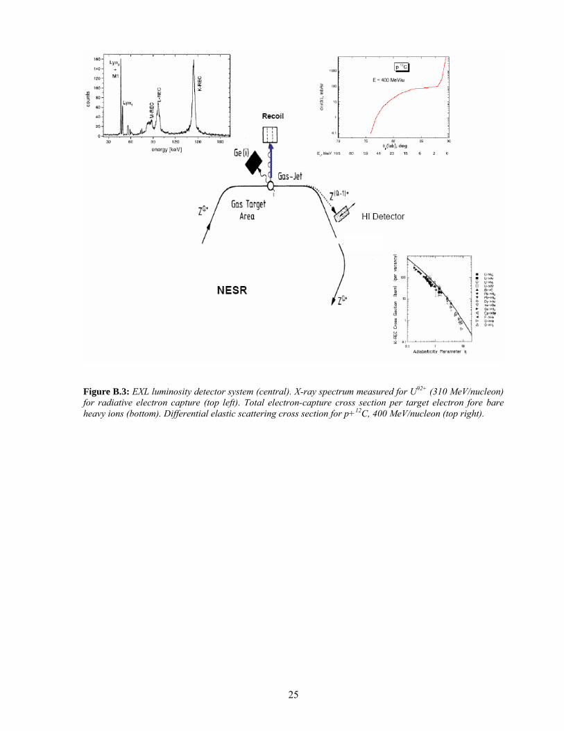
1.3 Luminosity monitor Reliable in-situ luminosity measurements are a crucial task. The luminosity depends, aside of the average target density and beam intensity, on quantities such as the exact target and beam profiles and their overlap as well as on the beam lifetime. A practical scheme of luminosity monitoring has to be found that is universal in a sense that it is applicable to different beams and beam energies (T) over a wide range. The basic requirements are: i) the luminosity measurement should be based on target-beam interaction cross sections which are large in order to allow for time-differential measurements without introducing additional statistical fluctuations, ii) the luminosity monitoring scheme should be applicable in a wide range of beam-target combinations and beam energies and intensities, iii) the cross sections of the reaction serving in the luminosity measurement need to be precisely known experimentally or should be perfectly under control theoretically, iv) the luminosity detector device should not impose restrictions onto the main detector setup. These demands infer that luminosity monitoring should be based on purely electromagnetic target-beam interaction processes; below we consider electron capture and Rutherford scattering. Both processes provide relatively large cross sections, which can be quantitatively computed. Atomic charge-exchange cross sections are well studied. Here the transfer of a (hydrogen, helium...) target electron into electron orbitals of the (under most circumstances fully stripped) projectile ion are of interest. Electron capture cross sections are known to obey simple scaling laws [Sto95, Sto98] and can thus be used. As obtained from the classical dipole approximation, capture cross sections per target electron essentially scale with the Sommerfeld adiabatic parameter η ~ T / Z2, and exact relativistic theoretical treatments are available, see inset in Figure B.3 for illustration. For example, the capture cross section of U92+ (300 MeV per nucleon) on hydrogen amounts to 80 b. Two schemes for monitoring the atomic charge-exchange reactions are foreseen for the EXL setup, shown schematically in Figure B.3. The total atomic charge-exchange yield is observed by detecting projectile-like ions of magnetic rigidity differing from that of the projectile according to the changed atomic charge state. Ion detectors placed behind the first NESR dipole magnet after the gas-jet target, the same detectors serving to detect projectile residues from nuclear reactions, are described in detail in section B.1.5. The scheme is, to some extent, hampered by the fact that atomic charge-exchange reactions also occur in the residual gas of the storage ring requiring corrections. The problem can be circumvented by Ge detectors viewing directly the target-beam interaction zone and measuring x-rays from radiative electron capture; such an arrangement, shown in Figure B.3, was applied by atomic physics groups studying these effects (see references cited above) at the ESR. Since usually bare ions are stored, the radiative capture into the projectile K-shell is of largest cross section; an x-ray spectrum taken for radiative capture at the ESR is shown in an inset of Figure B.3. Two Ge(i) detectors placed in the backward hemisphere behind the target covering about 1 ‰ of the 4π solid angle guarantee a count rate sufficient for luminosity monitoring in case of medium-heavy to heavy ion beams. The charge-exchange cross sections, however, become too small to be useful in the case of light projectiles and high beam energy. Small-angle elastic scattering of target and projectile, i.e. Coulomb scattering, is an alternative. For example, monitoring the proton recoil in Coulomb scattering of a 12C projectile (400 MeV per nucleon) at an angle of 89o yields ~ 1 b/sr cross section (see inset of Figure B.3), covering about 100 msr solid angle, yields about 10 counts/sec (target density: 1014 atoms/cm2; 108 ions stored); the Coulomb cross section scales with Zt
2 Zp2 / q4
(momentum transfer q). The corresponding detectors are an integral part of the EXL target-recoil detector, see section B.1.4. All three methods discussed above will be integrated simultaneously into the EXL apparatus.
25
Figure B.3: EXL luminosity detector system (central). X-ray spectrum measured for U92+ (310 MeV/nucleon) for radiative electron capture (top left). Total electron-capture cross section per target electron fore bare heavy ions (bottom). Differential elastic scattering cross section for p+12C, 400 MeV/nucleon (top right).
26
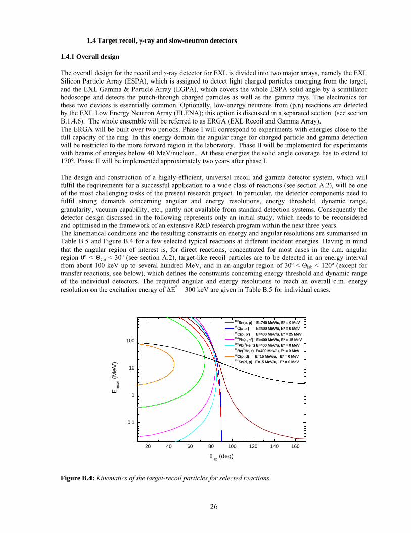
1.4 Target recoil, γ-ray and slow-neutron detectors 1.4.1 Overall design The overall design for the recoil and γ-ray detector for EXL is divided into two major arrays, namely the EXL Silicon Particle Array (ESPA), which is assigned to detect light charged particles emerging from the target, and the EXL Gamma & Particle Array (EGPA), which covers the whole ESPA solid angle by a scintillator hodoscope and detects the punch-through charged particles as well as the gamma rays. The electronics for these two devices is essentially common. Optionally, low-energy neutrons from (p,n) reactions are detected by the EXL Low Energy Neutron Array (ELENA); this option is discussed in a separated section (see section B.1.4.6). The whole ensemble will be referred to as ERGA (EXL Recoil and Gamma Array). The ERGA will be built over two periods. Phase I will correspond to experiments with energies close to the full capacity of the ring. In this energy domain the angular range for charged particle and gamma detection will be restricted to the more forward region in the laboratory. Phase II will be implemented for experiments with beams of energies below 40 MeV/nucleon. At these energies the solid angle coverage has to extend to 170°. Phase II will be implemented approximately two years after phase I. The design and construction of a highly-efficient, universal recoil and gamma detector system, which will fulfil the requirements for a successful application to a wide class of reactions (see section A.2), will be one of the most challenging tasks of the present research project. In particular, the detector components need to fulfil strong demands concerning angular and energy resolutions, energy threshold, dynamic range, granularity, vacuum capability, etc., partly not available from standard detection systems. Consequently the detector design discussed in the following represents only an initial study, which needs to be reconsidered and optimised in the framework of an extensive R&D research program within the next three years. The kinematical conditions and the resulting constraints on energy and angular resolutions are summarised in Table B.5 and Figure B.4 for a few selected typical reactions at different incident energies. Having in mind that the angular region of interest is, for direct reactions, concentrated for most cases in the c.m. angular region 0º < Θcm < 30º (see section A.2), target-like recoil particles are to be detected in an energy interval from about 100 keV up to several hundred MeV, and in an angular region of 30º < Θlab < 120º (except for transfer reactions, see below), which defines the constraints concerning energy threshold and dynamic range of the individual detectors. The required angular and energy resolutions to reach an overall c.m. energy resolution on the excitation energy of ∆E* = 300 keV are given in Table B.5 for individual cases.
20 40 60 80 100 120 140 160
0.1
1
10
100
E reco
il (MeV
)
θlab (deg)
132Sn(p, p) E=740 MeV/u, E* = 0 MeV 18C(α, α) E=400 MeV/u, E* = 0 MeV 18C(p, p') E=400 MeV/u, E* = 25 MeV 196Pb(α, α') E=400 MeV/u, E* = 15 MeV 196Pb(3He, t) E=400 MeV/u, E* = 0 MeV 12Be(3He, t) E=400 MeV/u, E* = 0 MeV 22C(p, d) E=15 MeV/u, E* = 0 MeV 132Sn(d, p) E=15 MeV/u, E* = 0 MeV
Figure B.4: Kinematics of the target-recoil particles for selected reactions.
27
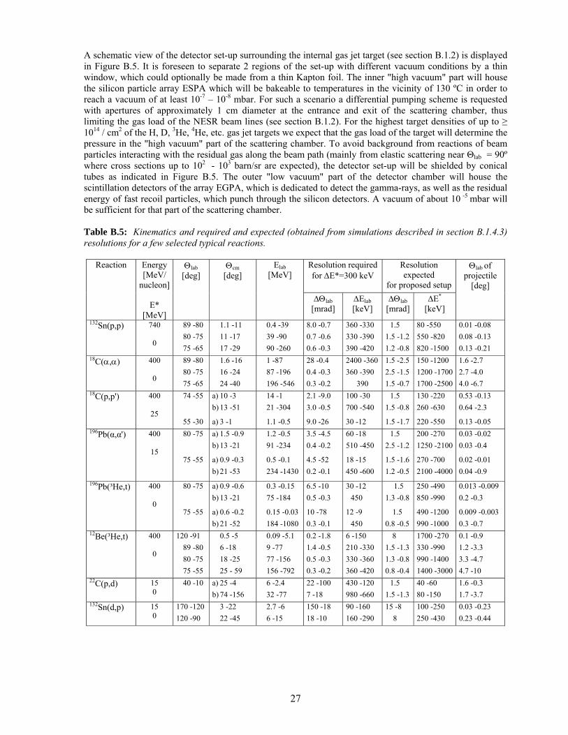
A schematic view of the detector set-up surrounding the internal gas jet target (see section B.1.2) is displayed in Figure B.5. It is foreseen to separate 2 regions of the set-up with different vacuum conditions by a thin window, which could optionally be made from a thin Kapton foil. The inner "high vacuum" part will house the silicon particle array ESPA which will be bakeable to temperatures in the vicinity of 130 ºC in order to reach a vacuum of at least 10-7 – 10-8 mbar. For such a scenario a differential pumping scheme is requested with apertures of approximately 1 cm diameter at the entrance and exit of the scattering chamber, thus limiting the gas load of the NESR beam lines (see section B.1.2). For the highest target densities of up to ≥ 1014 / cm2 of the H, D, 3He, 4He, etc. gas jet targets we expect that the gas load of the target will determine the pressure in the "high vacuum" part of the scattering chamber. To avoid background from reactions of beam particles interacting with the residual gas along the beam path (mainly from elastic scattering near Θlab = 90º where cross sections up to 102 - 103 barn/sr are expected), the detector set-up will be shielded by conical tubes as indicated in Figure B.5. The outer "low vacuum" part of the detector chamber will house the scintillation detectors of the array EGPA, which is dedicated to detect the gamma-rays, as well as the residual energy of fast recoil particles, which punch through the silicon detectors. A vacuum of about 10 -5 mbar will be sufficient for that part of the scattering chamber. Table B.5: Kinematics and required and expected (obtained from simulations described in section B.1.4.3) resolutions for a few selected typical reactions.
Resolution required for ∆E*=300 keV
Resolution expected
for proposed setup
Reaction Energy [MeV/
nucleon]
E* [MeV]
Θlab [deg]
Θcm [deg]
Elab [MeV]
∆Θlab [mrad]
∆Elab [keV]
∆Θlab [mrad]
∆E*
[keV]
Θlab of projectile
[deg]
132Sn(p,p) 740 0
89 -80 80 -75 75 -65
1.1 -11 11 -17 17 -29
0.4 -39 39 -90 90 -260
8.0 -0.7 0.7 -0.6 0.6 -0.3
360 -330 330 -390 390 -420
1.5 1.5 -1.2 1.2 -0.8
80 -550 550 -820 820 -1500
0.01 -0.08 0.08 -0.13 0.13 -0.21
18C(α,α) 400 0
89 -80 80 -75 75 -65
1.6 -16 16 -24 24 -40
1 -87 87 -196 196 -546
28 -0.4 0.4 -0.3 0.3 -0.2
2400 -360 360 -390
390
1.5 -2.5 2.5 -1.5 1.5 -0.7
150 -1200 1200 -1700 1700 -2500
1.6 -2.7 2.7 -4.0 4.0 -6.7
18C(p,p') 400
25
74 -55
55 -30
a) 10 -3 b) 13 -51
a) 3 -1
14 -1 21 -304
1.1 -0.5
2.1 -9.0 3.0 -0.5
9.0 -26
100 -30 700 -540
30 -12
1.5 1.5 -0.8
1.5 -1.7
130 -220 260 -630
220 -550
0.53 -0.13 0.64 -2.3
0.13 -0.05 196Pb(α,α') 400
15
80 -75
75 -55
a) 1.5 -0.9 b) 13 -21
a) 0.9 -0.3 b) 21 -53
1.2 -0.5 91 -234
0.5 -0.1 234 -1430
3.5 -4.5 0.4 -0.2
4.5 -52 0.2 -0.1
60 -18 510 -450
18 -15 450 -600
1.5 2.5 -1.2
1.5 -1.6 1.2 -0.5
200 -270 1250 -2100
270 -700 2100 -4000
0.03 -0.02 0.03 -0.4
0.02 -0.01 0.04 -0.9
196Pb(³He,t) 400 0
80 -75
75 -55
a) 0.9 -0.6 b) 13 -21
a) 0.6 -0.2 b) 21 -52
0.3 -0.15 75 -184
0.15 -0.03 184 -1080
6.5 -10 0.5 -0.3
10 -78 0.3 -0.1
30 -12 450
12 -9 450
1.5 1.3 -0.8
1.5 0.8 -0.5
250 -490 850 -990
490 -1200 990 -1000
0.013 -0.009 0.2 -0.3
0.009 -0.003 0.3 -0.7
12Be(³He,t)
400 0
120 -91 89 -80 80 -75 75 -55
0.5 -5 6 -18 18 -25 25 - 59
0.09 -5.1 9 -77 77 -156 156 -792
0.2 -1.8 1.4 -0.5 0.5 -0.3 0.3 -0.2
6 -150 210 -330 330 -360 360 -420
8 1.5 -1.3 1.3 -0.8 0.8 -0.4
1700 -270 330 -990 990 -1400 1400 -3000
0.1 -0.9 1.2 -3.3 3.3 -4.7 4.7 -10
22C(p,d) 15 0
40 -10 a) 25 -4 b) 74 -156
6 -2.4 32 -77
22 -100 7 -18
430 -120 980 -660
1.5 1.5 -1.3
40 -60 80 -150
1.6 -0.3 1.7 -3.7
132Sn(d,p) 15 0
170 -120 120 -90
3 -22 22 -45
2.7 -6 6 -15
150 -18 18 -10
90 -160 160 -290
15 -8 8
100 -250 250 -430
0.03 -0.23 0.23 -0.44
28
1.4.2 Detector geometry
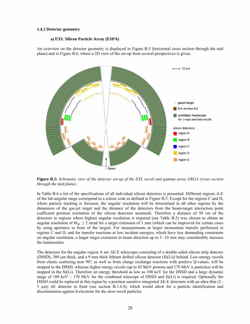
a) EXL Silicon Particle Array (ESPA) An overview on the detector geometry is displayed in Figure B.5 (horizontal cross section through the mid plane) and in Figure B.6, where a 3D view of the set-up from several perspectives is given.
Figure B.5: Schematic view of the detector set-up of the EXL recoil and gamma array ERGA (cross section through the mid plane). In Table B.6 a list of the specifications of all individual silicon detectors is presented. Different regions A-E of the lab-angular range correspond to a colour code as defined in Figure B.5. Except for the regions C and D, where particle tracking is foreseen, the angular resolution will be determined in all other regions by the dimension of the gas-jet target and the distance of the detectors from the beam-target interaction point (sufficient position resolution of the silicon detectors assumed). Therefore a distance of 50 cm of the detectors in regions where highest angular resolution is required (see Table B.5) was chosen to obtain an angular resolution of Θlab ≤ 2 mrad for a target extension of 1 mm (which can be improved for certain cases by using apertures in front of the target). For measurements at larger momentum transfer performed in regions C and D, and for transfer reactions at low incident energies, which have less demanding constraints on angular resolution, a larger target extension in beam direction up to 5 -10 mm may considerably increase the luminosities. The detectors for the angular region A are ∆E-E telescopes consisting of a double-sided silicon strip detector (DSSD), 300 µm thick, and a 9 mm thick lithium drifted silicon detector (Si(Li)) behind. Low-energy recoils from elastic scattering near 90º, as well as from charge exchange reactions with positive Q-values, will be stopped in the DSSD, whereas higher energy recoils (up to 45 MeV protons and 170 MeV α particles) will be stopped in the Si(Li). Therefore an energy threshold as low as 100 keV for the DSSD and a large dynamic range of 100 keV – 170 MeV for the combined telescope of DSSD and Si(Li) is required. Optionally the DSSD could be replaced in this region by a position sensitive integrated ∆E-E detectors with an ultra-thin (2 -5 µm) ∆E detector in front (see section B.1.4.4), which would allow for a particle identification and discrimination against δ-electrons for the slow recoil particles.
29
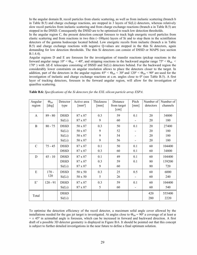
In the angular domain B, recoil particles from elastic scattering, as well as from inelastic scattering (branch b in Table B.5) and charge exchange reactions, are stopped in 3 layers of Si(Li) detectors, whereas relatively slow recoil particles from inelastic scattering and from charge exchange reactions (branch a in Table B.5) are stopped in the DSSD. Consequently the DSSD are to be optimised to reach low detection thresholds. In the angular region C, the present detection concept foresees to track high energetic recoil particles from elastic scattering and from reactions in two thin (~100µm) layers of Si and to stop them in the scintillation detectors of the gamma hodoscope located behind. Low energetic recoils from inelastic (branch a in Table B.5) and charge exchange reactions with negative Q-values are stopped in the thin Si detectors, again demanding for low detection thresholds. The thin Si detectors can consist of DSSD or MAPS (see section B.1.4.4). Angular regions D and E are foreseen for the investigation of transfer reactions (pickup reactions in the forward angular range 10º < Θlab < 40º, and stripping reactions in the backward angular range 75º < Θlab < 170º ) with ∆E-E telescopes consisting of DSSD and Si(Li) detectors behind. For the backward region the considerably lower constraints on angular resolution allows to place the detectors closer to the target. In addition, part of the detectors in the angular regions 45º < Θlab < 30º and 120º < Θlab < 90º are used for the investigation of inelastic and charge exchange reactions at c.m. angles close to 0º (see Table B.5). A first layer of tracking detectors, foreseen in the forward angular region, will allow for the investigation of quasifree scattering. Table B.6: Specifications of the Si detectors for the EXL silicon particle array ESPA. Angular region
Θlab [deg]
Detector type
Active area [mm²]
Thickness [mm]
Distance from target
[cm]
Pitch [mm]
Number of detectors
Number of channels
A 89 - 80 DSSD Si(Li)
87 x 87 87 x 87
0.3 9
59 60
0.1 -
20 20
34800 180
B 80 - 75 DSSD Si(Li) Si(Li) Si(Li)
50 x 87 50 x 87 50 x 87 50 x 87
0.3 9 9 9
50 52 54 56
0.1 - - -
20 20 20 20
27400 180 180 180
C 75 - 45 DSSD DSSD
87 x 87 87 x 87
0.1 0.3
50 60
0.1 0.1
60 60
104400 34800
D 45 - 10 DSSD DSSD Si(Li)
87 x 87 87 x 87 87 x 87
0.1 0.3 9
49 59 60
0.1 0.1
60 80 80
104400 139200
720
E 170 - 120
DSSD Si(Li)
50 x 50 50 x 50
0.3 5
25 26
0.5 -
60 60
6000 240
E’ 120 - 91 DSSD Si(Li)
87 x 87 87 x 87
0.3 5
59 60
0.1 -
60 60
104400 540
Total DSSD
Si(Li) 420
280 555400
2220 To optimise the detection efficiency of the recoil detector, a maximum solid angle cover allowed by the installations needed for the gas jet target is investigated. At angles close to Θlab = 90º a coverage of at least φ = ± 45º in azimuthal angle is foreseen, which can be increased in forward and backward direction. A first draft of a possible 3D detector geometry is displayed in Figure B.6. It should be pointed out that this concept is subject to further detailed investigations in the near future to define a final optimum solution.
30
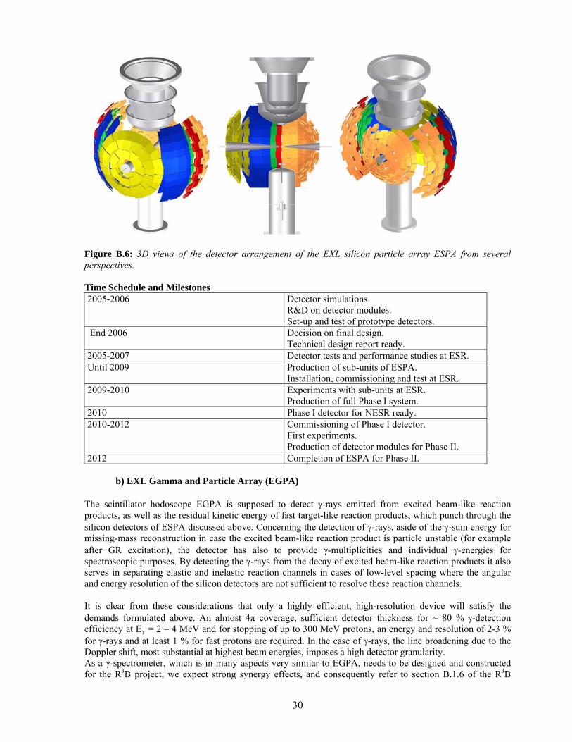
Figure B.6: 3D views of the detector arrangement of the EXL silicon particle array ESPA from several perspectives. Time Schedule and Milestones 2005-2006 Detector simulations.
R&D on detector modules. Set-up and test of prototype detectors.
End 2006 Decision on final design. Technical design report ready.
2005-2007 Detector tests and performance studies at ESR. Until 2009 Production of sub-units of ESPA.
Installation, commissioning and test at ESR. 2009-2010 Experiments with sub-units at ESR.
Production of full Phase I system. 2010 Phase I detector for NESR ready. 2010-2012 Commissioning of Phase I detector.
First experiments. Production of detector modules for Phase II.
2012 Completion of ESPA for Phase II.
b) EXL Gamma and Particle Array (EGPA) The scintillator hodoscope EGPA is supposed to detect γ-rays emitted from excited beam-like reaction products, as well as the residual kinetic energy of fast target-like reaction products, which punch through the silicon detectors of ESPA discussed above. Concerning the detection of γ-rays, aside of the γ-sum energy for missing-mass reconstruction in case the excited beam-like reaction product is particle unstable (for example after GR excitation), the detector has also to provide γ-multiplicities and individual γ-energies for spectroscopic purposes. By detecting the γ-rays from the decay of excited beam-like reaction products it also serves in separating elastic and inelastic reaction channels in cases of low-level spacing where the angular and energy resolution of the silicon detectors are not sufficient to resolve these reaction channels. It is clear from these considerations that only a highly efficient, high-resolution device will satisfy the demands formulated above. An almost 4π coverage, sufficient detector thickness for ~ 80 % γ-detection efficiency at Eγ = 2 – 4 MeV and for stopping of up to 300 MeV protons, an energy and resolution of 2-3 % for γ-rays and at least 1 % for fast protons are required. In the case of γ-rays, the line broadening due to the Doppler shift, most substantial at highest beam energies, imposes a high detector granularity. As a γ-spectrometer, which is in many aspects very similar to EGPA, needs to be designed and constructed for the R3B project, we expect strong synergy effects, and consequently refer to section B.1.6 of the R3B
31
Technical Proposal, where details on the kinematical properties, the geometrical considerations, and several scenarios with different crystal materials are presented. The EGPA geometry is displayed in Figures B.5. and B.7. In contrast to R3B, a coverage of the full angular range 10º < Θlab < 170º is foreseen, since transfer reactions, which need to be investigated at relatively low incident energies where no pronounced Lorentz-boost in forward direction appears, are included in the experimental program. An effective thickness of the scintillator crystals of 20 cm, corresponding to about 10 radiation lengths for 4 MeV γ-rays, is foreseen. Several scintillator materials including cooled CsI crystals are presently under consideration, and an extended R&D program within the next 2 years is planned to find the optimum solution with respect to the required performance discussed above. From a computation of the Doppler line broadening, it appears that the angular coverage of individual crystals has to be restricted to bins in γ-ray polar emission angle of ∆Θlab = 1 - 4º, depending on the emission angle. This will allow to achieve the required energy resolution even at highest beam energies. A preliminary design study of the geometrical 3D arrangement of the EGPA crystals is displayed in Figure B.7. The solid angle of interest is covered by a total number of about 2000 crystals configured in a dense packing with a total active volume of 0.7 m³. In a first phase, where only investigations at high incident energies are planned (see section B.1.4.1), we intend to cover only the forward hemisphere; in phase II the set-up will include the backward hemisphere. Time Schedule and Milestones 2005-2006 Detector simulation.
R&D on detector modules. Set-up and test of prototype modules.
End 2006 Decision on final design. Technical design report ready.
2005-2007 Detector tests and performance studies. 2007-2008 Construction.
Crystal production for 20% sub-units. Crystal tests.
2008-2009 Test of 20 % sub-units with external beams. Crystal production and test.
2010 Phase I detector ready. 2010-2012 Commissioning of phase I detector.
First experiments. Production of detector modules for phase II.
2012 Completion of EGPA for phase II.
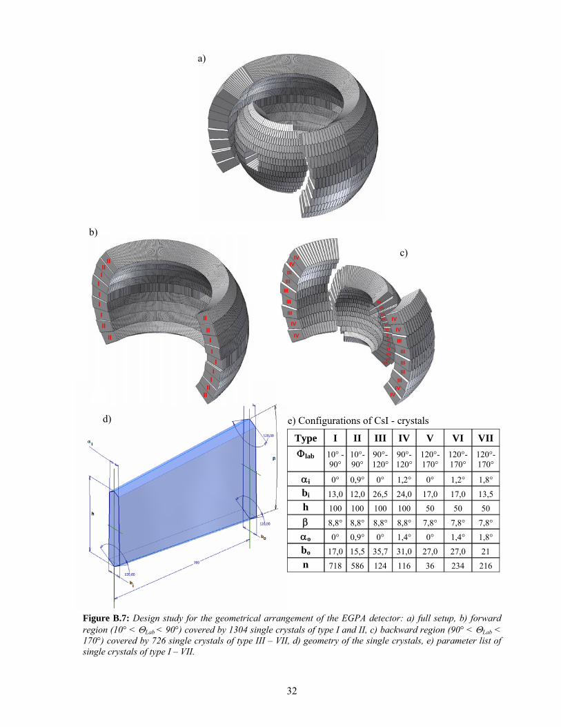
32
Figure B.7: Design study for the geometrical arrangement of the EGPA detector: a) full setup, b) forward region (10° < ΘLab < 90°) covered by 1304 single crystals of type I and II, c) backward region (90° < ΘLab < 170°) covered by 726 single crystals of type III – VII, d) geometry of the single crystals, e) parameter list of single crystals of type I – VII.
II
II I
I
I I I
I I
II II
II
II
II II
I I I
IV
IV
IVIV
III
III
IIIIIIIII
III
III
III
IIIIII
IV
IV
IVIV
VII
VIIVI
VII
VIVIV
VIVI
VIVII
VIIVII
IV
IV
IVIV
III
III
IIIIIIIII
III
III
III
IIIIII
IV
IV
IVIV
VII
VIIVI
VII
VIVIV
VIVI
VIVII
VIIVII
e) Configurations of CsI - crystals
Type I II III IV V VI VII Φlab 10° -
90° 10°- 90°
90°-120°
90°-120°
120°-170°
120°-170°
120°-170°
αi 0° 0,9° 0° 1,2° 0° 1,2° 1,8° bi 13,0 12,0 26,5 24,0 17,0 17,0 13,5 h 100 100 100 100 50 50 50 β 8,8° 8,8° 8,8° 8,8° 7,8° 7,8° 7,8° αo 0° 0,9° 0° 1,4° 0° 1,4° 1,8° bo 17,0 15,5 35,7 31,0 27,0 27,0 21 n 718 586 124 116 36 234 216
d)
c)
a)
b)
33
1.4.3 Simulations on the performance of the detection system As already discussed above, the main requirements are high resolutions for momentum and energy of the recoiling target nuclei and a low detection threshold. Detailed simulation studies of the performance of the suggested detector scheme will show its feasibility. Some initial simulations have already been carried out. The simulation package is based on the general-purpose transport tool Geant4 [Ago03]. It is able to trace particles through various layers of material, generate secondary particles according to the interaction cross sections and the decay probabilities of the incident particles, as well as to calculate their energy loss and time-of-flight. The analysis of the simulated events is done using the histogram tool ROOT [Bru97]. The recoil particles are generated using external event generators. The main results of the simulations carried out so far have been obtained for one of the most demanding type of reaction, namely inelastic scattering. The aim of the simulation is to find the conditions which optimise the detection system in terms of its tracking capability and detection with good energy and angular resolution and particle identification. In particular the focus is on the following points: tracking section – distance from the target to the first Si micro-strip layer, distance between the layers,
thickness of the 1st layer, strip pitch, thickness of the 2nd layer, strip pitch non-tracking section – distance from the target to the detector, thickness of the layer, strip pitch thickness and material of the vacuum chamber wall thickness and material of the scintillator hodoscope energy resolution for combination of several detectors
The most important parameters of the detector system are resolutions on excitation energy and on centre-of-mass scattering angle, derived from the recoil energy and angle measured in the laboratory. These values have been calculated for the detector geometry as described in section B.1.4.2. To demonstrate the influence of the thickness of the first tracking detector this parameter was varied from 30 to 100 µm. As for the quality of the stored beam and the intrinsic detector resolutions the following assumptions (based on known test results) were made:
• beam diameter: 1 mm; • energy resolution of the silicon detectors: 50 keV ( FWHM ) • energy resolution of the scintillation detectors: 1 % ( FWHM )
Within the simulations performed all extracted parameters are folded with the respective resolutions. The coordinate determination is based on the strip width in the micro-strip detectors. The resolution on excitation energy ∆E* (σ) versus proton recoil energy Ep for the case of inelastic scattering of 12C(p,p’) with E = 400 MeV/nucleon is shown on the left-hand panel of Figure B.8. The resolution on the centre-of-mass angle ∆θ (σ) versus Ep for the same reaction is shown in the right-hand panel of Figure B.8. The results of the simulations for the higher energy (E = 740 MeV/nucleon) and heavier ions (132Sn, 187Pb) are plotted in Figures B.9 and B.10. Different detector arrangements are adopted:
• two layers of strip detectors (tracking section) choosing thicknesses varying from 30 to 100 µm, relevant for the detection of particles of higher energy, e.g., protons above ~ 50 MeV, and
• only one layer of strip detectors (non-tracking section), relevant for the low-momentum transfer reactions such as inelastic excitation, charge exchange, or elastic scattering close to 90o.
The following conclusions are drawn:
• The results are rather independent on the choice of the beam species and beam energy. • The resolution in c.m. scattering ranges between 0.1o – 0.3o (FWHM) which is even better than the
physics requirements (0.5o binning is enough in most of the cases). • The resolution in excitation energy amounts to a few hundred keV for low-momentum transfer
according to the design goals, and to about 0.5 – 1 MeV in the high-momentum transfer regime. Summarizing, the EXL recoil detector concept as outlined in this proposal appears to be basically capable fulfilling the physics requirement. Future simulation studies will contribute finding modifications which improve the detector performance.
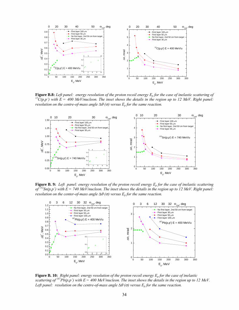
34
0 50 100 150 200 250 300 3500.1
0.2
0.3
0.4
0.5
0.6
0.7
0.8
0.9
0 3 6 9 120.0
0.1
0.2
0 5 10
0 20 30 40 50 ΘCM, deg
12C(p,p') E = 400 MeV/u
First layer 100 µm First layer 50 µm No first layer, 2nd 50 cm from target First layer 30 µm
∆E* , M
eV
Ep, MeV
Figure B.8: Left panel: energy resolution of the proton recoil energy Ep for the case of inelastic scattering of 12C(p,p’) with E = 400 MeV/nucleon. The inset shows the details in the region up to 12 MeV. Right panel: resolution on the centre-of-mass angle ∆θ (σ) versus Ep for the same reaction.
0 50 100 150 200 250 300 3500.00
0.25
0.50
0.75
1.00
1.25
1.50
0 3 6 9 120.0
0.1
0.2
0.3
0 3 6
0 10 20 30 ΘCM, deg
132Sn(p,p') E = 740 MeV/u
First layer 100 µm First layer 50 µm No first layer, 2nd 50 cm from target First layer 30 µm
∆E* , M
eV
Ep, MeV
Figure B. 9: Left panel: energy resolution of the proton recoil energy Ep for the case of inelastic scattering of 132Sn(p,p’) with E = 740 MeV/nucleon. The inset shows the details in the region up to 12 MeV. Right panel: resolution on the center-of-mass angle ∆θ (σ) versus Ep for the same reaction.
0 50 100 150 200 250 300 3500.0
0.1
0.2
0.3
0.4
0.5
0.6
0.7
0.8
0.9
1.0
1.1
1.2
0 3 6 9 120.0
0.1
0.2
0 3 6 12 30 32 ΘCM, deg
187Pb(p,p') E = 400 MeV/u
No first layer, 2nd 50 cm from target First layer 30 µm First layer 50 µm First layer 100 µm
∆E* , M
eV
Ep, MeV
Figure B. 10: Right panel: energy resolution of the proton recoil energy Ep for the case of inelastic scattering of 187Pb(p,p’) with E = 400 MeV/nucleon. The inset shows the details in the region up to 12 MeV. Left panel: resolution on the centre-of-mass angle ∆θ (σ) versus Ep for the same reaction.
0 50 100 150 200 250 300 3500
1
2
3
4
50 10 20 30 ΘCM, deg
132Sn(p,p') E = 740 MeV/u
First layer 100 µm First layer 50 µm No first layer, 2nd 50 cm from target First layer 30 µm
∆Θ, m
rad
Ep, MeV
0 50 100 150 200 250 300 3500
1
2
3
4
5
6
12C(p,p') E = 400 MeV/u
First layer 100 µm First layer 50 µm No first layer, 2nd 50 cm from target First layer 30 µm
∆Θ, m
rad
Ep, MeV
0 20 30 40 50 ΘCM, deg
0 50 100 150 200 250 300 3500
1
2
3
0 3 6 12 30 32 ΘCM, deg
187Pb(p,p') E = 400 MeV/u
No first layer, 2nd 50 cm from target First layer 30 µm First layer 50 µm First layer 100 µm
∆Θ, m
rad
Ep, MeV
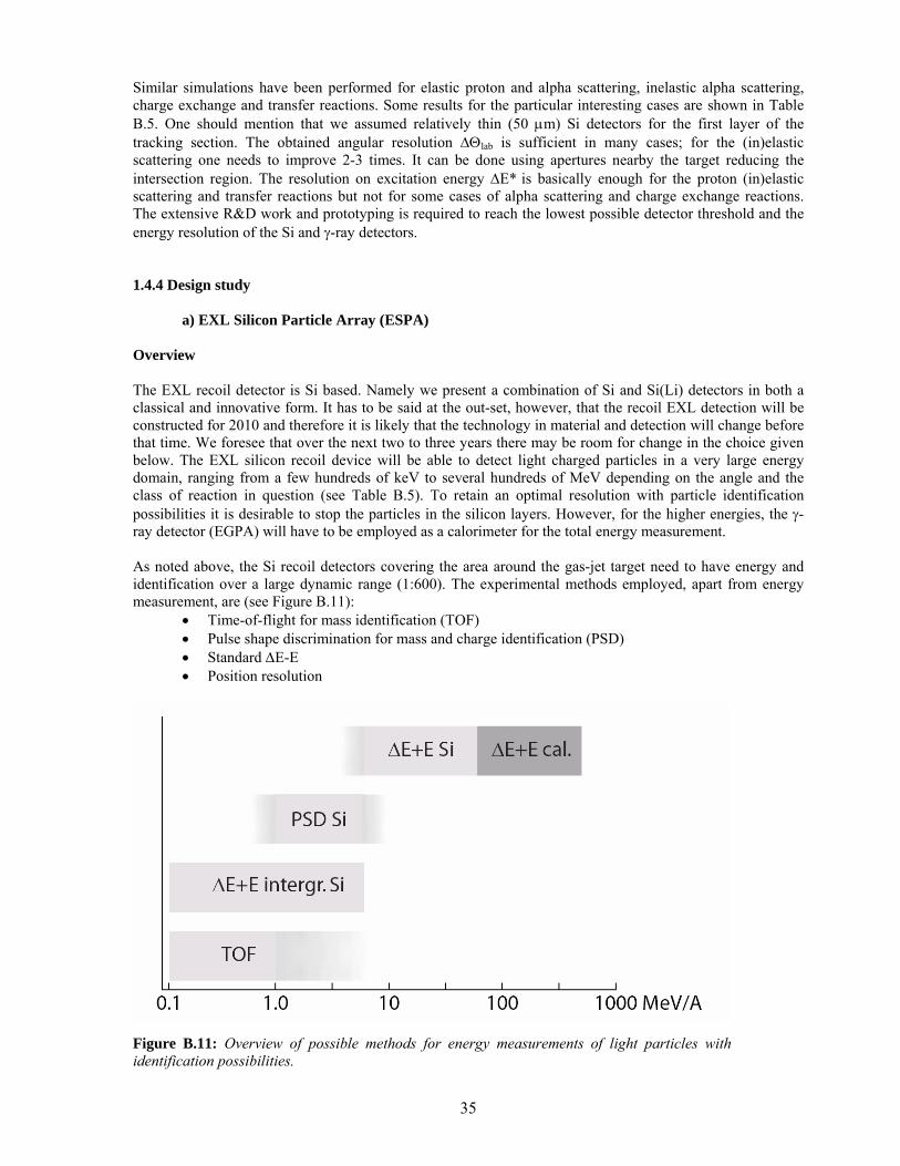
35
Similar simulations have been performed for elastic proton and alpha scattering, inelastic alpha scattering, charge exchange and transfer reactions. Some results for the particular interesting cases are shown in Table B.5. One should mention that we assumed relatively thin (50 µm) Si detectors for the first layer of the tracking section. The obtained angular resolution ∆Θlab is sufficient in many cases; for the (in)elastic scattering one needs to improve 2-3 times. It can be done using apertures nearby the target reducing the intersection region. The resolution on excitation energy ∆E* is basically enough for the proton (in)elastic scattering and transfer reactions but not for some cases of alpha scattering and charge exchange reactions. The extensive R&D work and prototyping is required to reach the lowest possible detector threshold and the energy resolution of the Si and γ-ray detectors. 1.4.4 Design study
a) EXL Silicon Particle Array (ESPA) Overview The EXL recoil detector is Si based. Namely we present a combination of Si and Si(Li) detectors in both a classical and innovative form. It has to be said at the out-set, however, that the recoil EXL detection will be constructed for 2010 and therefore it is likely that the technology in material and detection will change before that time. We foresee that over the next two to three years there may be room for change in the choice given below. The EXL silicon recoil device will be able to detect light charged particles in a very large energy domain, ranging from a few hundreds of keV to several hundreds of MeV depending on the angle and the class of reaction in question (see Table B.5). To retain an optimal resolution with particle identification possibilities it is desirable to stop the particles in the silicon layers. However, for the higher energies, the γ-ray detector (EGPA) will have to be employed as a calorimeter for the total energy measurement. As noted above, the Si recoil detectors covering the area around the gas-jet target need to have energy and identification over a large dynamic range (1:600). The experimental methods employed, apart from energy measurement, are (see Figure B.11):
• Time-of-flight for mass identification (TOF) • Pulse shape discrimination for mass and charge identification (PSD) • Standard ∆E-E • Position resolution
Figure B.11: Overview of possible methods for energy measurements of light particles with identification possibilities.
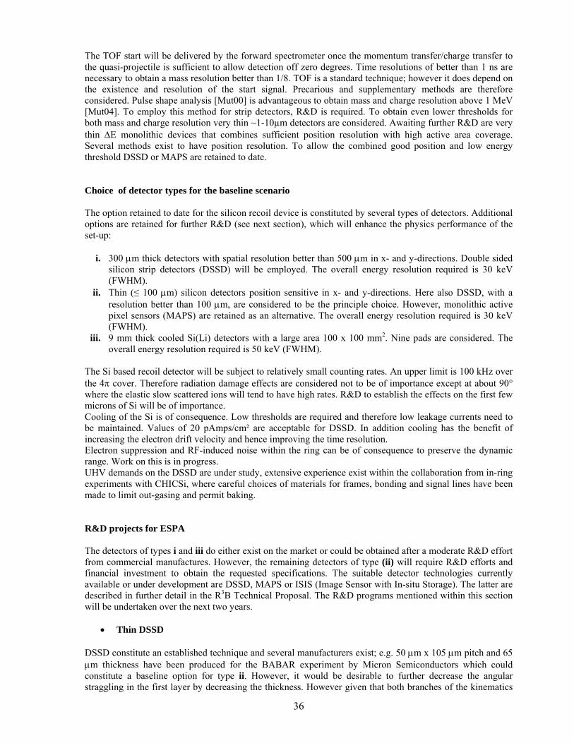
36
The TOF start will be delivered by the forward spectrometer once the momentum transfer/charge transfer to the quasi-projectile is sufficient to allow detection off zero degrees. Time resolutions of better than 1 ns are necessary to obtain a mass resolution better than 1/8. TOF is a standard technique; however it does depend on the existence and resolution of the start signal. Precarious and supplementary methods are therefore considered. Pulse shape analysis [Mut00] is advantageous to obtain mass and charge resolution above 1 MeV [Mut04]. To employ this method for strip detectors, R&D is required. To obtain even lower thresholds for both mass and charge resolution very thin ~1-10µm detectors are considered. Awaiting further R&D are very thin ∆E monolithic devices that combines sufficient position resolution with high active area coverage. Several methods exist to have position resolution. To allow the combined good position and low energy threshold DSSD or MAPS are retained to date. Choice of detector types for the baseline scenario The option retained to date for the silicon recoil device is constituted by several types of detectors. Additional options are retained for further R&D (see next section), which will enhance the physics performance of the set-up:
i. 300 µm thick detectors with spatial resolution better than 500 µm in x- and y-directions. Double sided silicon strip detectors (DSSD) will be employed. The overall energy resolution required is 30 keV (FWHM).
ii. Thin (≤ 100 µm) silicon detectors position sensitive in x- and y-directions. Here also DSSD, with a resolution better than 100 µm, are considered to be the principle choice. However, monolithic active pixel sensors (MAPS) are retained as an alternative. The overall energy resolution required is 30 keV (FWHM).
iii. 9 mm thick cooled Si(Li) detectors with a large area 100 x 100 mm2. Nine pads are considered. The overall energy resolution required is 50 keV (FWHM).
The Si based recoil detector will be subject to relatively small counting rates. An upper limit is 100 kHz over the 4π cover. Therefore radiation damage effects are considered not to be of importance except at about 90° where the elastic slow scattered ions will tend to have high rates. R&D to establish the effects on the first few microns of Si will be of importance. Cooling of the Si is of consequence. Low thresholds are required and therefore low leakage currents need to be maintained. Values of 20 pAmps/cm² are acceptable for DSSD. In addition cooling has the benefit of increasing the electron drift velocity and hence improving the time resolution. Electron suppression and RF-induced noise within the ring can be of consequence to preserve the dynamic range. Work on this is in progress. UHV demands on the DSSD are under study, extensive experience exist within the collaboration from in-ring experiments with CHICSi, where careful choices of materials for frames, bonding and signal lines have been made to limit out-gasing and permit baking. R&D projects for ESPA The detectors of types i and iii do either exist on the market or could be obtained after a moderate R&D effort from commercial manufactures. However, the remaining detectors of type (ii) will require R&D efforts and financial investment to obtain the requested specifications. The suitable detector technologies currently available or under development are DSSD, MAPS or ISIS (Image Sensor with In-situ Storage). The latter are described in further detail in the R3B Technical Proposal. The R&D programs mentioned within this section will be undertaken over the next two years.
• Thin DSSD DSSD constitute an established technique and several manufacturers exist; e.g. 50 µm x 105 µm pitch and 65 µm thickness have been produced for the BABAR experiment by Micron Semiconductors which could constitute a baseline option for type ii. However, it would be desirable to further decrease the angular straggling in the first layer by decreasing the thickness. However given that both branches of the kinematics
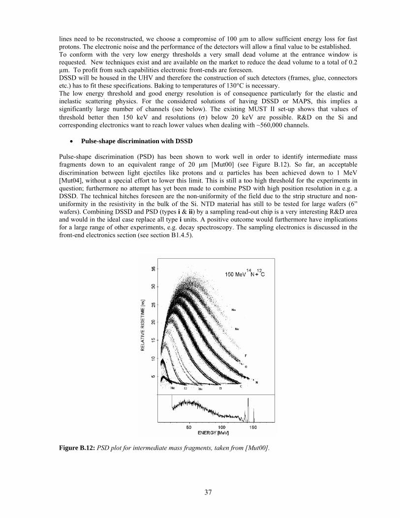
37
lines need to be reconstructed, we choose a compromise of 100 µm to allow sufficient energy loss for fast protons. The electronic noise and the performance of the detectors will allow a final value to be established. To conform with the very low energy thresholds a very small dead volume at the entrance window is requested. New techniques exist and are available on the market to reduce the dead volume to a total of 0.2 µm. To profit from such capabilities electronic front-ends are foreseen. DSSD will be housed in the UHV and therefore the construction of such detectors (frames, glue, connectors etc.) has to fit these specifications. Baking to temperatures of 130°C is necessary. The low energy threshold and good energy resolution is of consequence particularly for the elastic and inelastic scattering physics. For the considered solutions of having DSSD or MAPS, this implies a significantly large number of channels (see below). The existing MUST II set-up shows that values of threshold better then 150 keV and resolutions (σ) below 20 keV are possible. R&D on the Si and corresponding electronics want to reach lower values when dealing with ~560,000 channels.
• Pulse-shape discrimination with DSSD Pulse-shape discrimination (PSD) has been shown to work well in order to identify intermediate mass fragments down to an equivalent range of 20 µm [Mut00] (see Figure B.12). So far, an acceptable discrimination between light ejectiles like protons and α particles has been achieved down to 1 MeV [Mut04], without a special effort to lower this limit. This is still a too high threshold for the experiments in question; furthermore no attempt has yet been made to combine PSD with high position resolution in e.g. a DSSD. The technical hitches foreseen are the non-uniformity of the field due to the strip structure and non-uniformity in the resistivity in the bulk of the Si. NTD material has still to be tested for large wafers (6” wafers). Combining DSSD and PSD (types i & ii) by a sampling read-out chip is a very interesting R&D area and would in the ideal case replace all type i units. A positive outcome would furthermore have implications for a large range of other experiments, e.g. decay spectroscopy. The sampling electronics is discussed in the front-end electronics section (see section B1.4.5).
Figure B.12: PSD plot for intermediate mass fragments, taken from [Mut00].
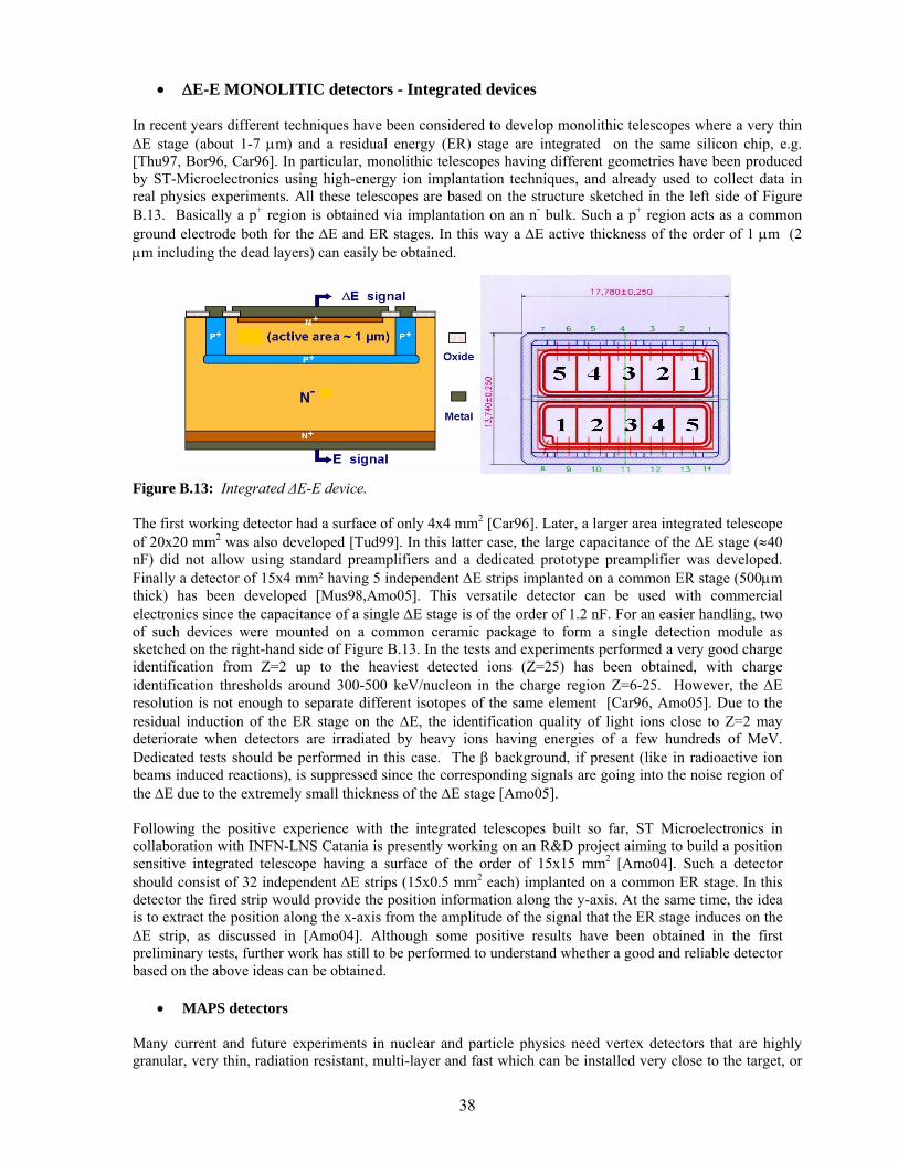
38
• ∆E-E MONOLITIC detectors - Integrated devices In recent years different techniques have been considered to develop monolithic telescopes where a very thin ∆E stage (about 1-7 µm) and a residual energy (ER) stage are integrated on the same silicon chip, e.g. [Thu97, Bor96, Car96]. In particular, monolithic telescopes having different geometries have been produced by ST-Microelectronics using high-energy ion implantation techniques, and already used to collect data in real physics experiments. All these telescopes are based on the structure sketched in the left side of Figure B.13. Basically a p+ region is obtained via implantation on an n- bulk. Such a p+ region acts as a common ground electrode both for the ∆E and ER stages. In this way a ∆E active thickness of the order of 1 µm (2 µm including the dead layers) can easily be obtained.
Figure B.13: Integrated ∆E-E device. The first working detector had a surface of only 4x4 mm2 [Car96]. Later, a larger area integrated telescope of 20x20 mm2 was also developed [Tud99]. In this latter case, the large capacitance of the ∆E stage (≈40 nF) did not allow using standard preamplifiers and a dedicated prototype preamplifier was developed. Finally a detector of 15x4 mm² having 5 independent ∆E strips implanted on a common ER stage (500µm thick) has been developed [Mus98,Amo05]. This versatile detector can be used with commercial electronics since the capacitance of a single ∆E stage is of the order of 1.2 nF. For an easier handling, two of such devices were mounted on a common ceramic package to form a single detection module as sketched on the right-hand side of Figure B.13. In the tests and experiments performed a very good charge identification from Z=2 up to the heaviest detected ions (Z=25) has been obtained, with charge identification thresholds around 300-500 keV/nucleon in the charge region Z=6-25. However, the ∆E resolution is not enough to separate different isotopes of the same element [Car96, Amo05]. Due to the residual induction of the ER stage on the ∆E, the identification quality of light ions close to Z=2 may deteriorate when detectors are irradiated by heavy ions having energies of a few hundreds of MeV. Dedicated tests should be performed in this case. The β background, if present (like in radioactive ion beams induced reactions), is suppressed since the corresponding signals are going into the noise region of the ∆E due to the extremely small thickness of the ∆E stage [Amo05]. Following the positive experience with the integrated telescopes built so far, ST Microelectronics in collaboration with INFN-LNS Catania is presently working on an R&D project aiming to build a position sensitive integrated telescope having a surface of the order of 15x15 mm2 [Amo04]. Such a detector should consist of 32 independent ∆E strips (15x0.5 mm2 each) implanted on a common ER stage. In this detector the fired strip would provide the position information along the y-axis. At the same time, the idea is to extract the position along the x-axis from the amplitude of the signal that the ER stage induces on the ∆E strip, as discussed in [Amo04]. Although some positive results have been obtained in the first preliminary tests, further work has still to be performed to understand whether a good and reliable detector based on the above ideas can be obtained.
• MAPS detectors Many current and future experiments in nuclear and particle physics need vertex detectors that are highly granular, very thin, radiation resistant, multi-layer and fast which can be installed very close to the target, or
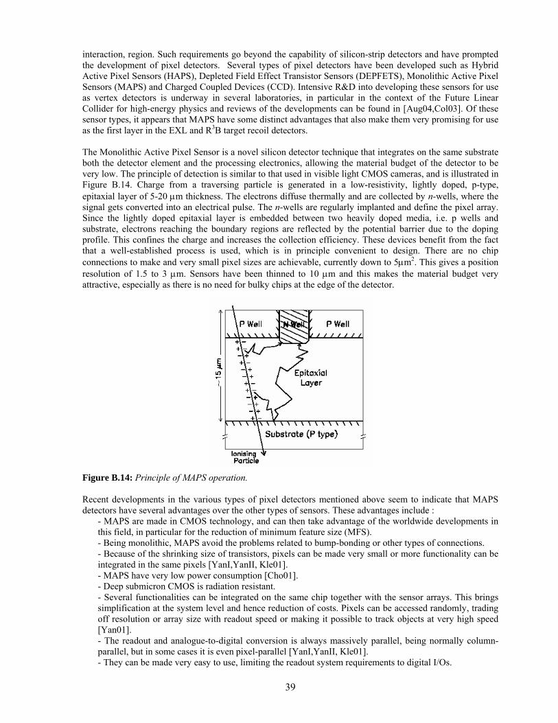
39
interaction, region. Such requirements go beyond the capability of silicon-strip detectors and have prompted the development of pixel detectors. Several types of pixel detectors have been developed such as Hybrid Active Pixel Sensors (HAPS), Depleted Field Effect Transistor Sensors (DEPFETS), Monolithic Active Pixel Sensors (MAPS) and Charged Coupled Devices (CCD). Intensive R&D into developing these sensors for use as vertex detectors is underway in several laboratories, in particular in the context of the Future Linear Collider for high-energy physics and reviews of the developments can be found in [Aug04,Col03]. Of these sensor types, it appears that MAPS have some distinct advantages that also make them very promising for use as the first layer in the EXL and R3B target recoil detectors.
The Monolithic Active Pixel Sensor is a novel silicon detector technique that integrates on the same substrate both the detector element and the processing electronics, allowing the material budget of the detector to be very low. The principle of detection is similar to that used in visible light CMOS cameras, and is illustrated in Figure B.14. Charge from a traversing particle is generated in a low-resistivity, lightly doped, p-type, epitaxial layer of 5-20 µm thickness. The electrons diffuse thermally and are collected by n-wells, where the signal gets converted into an electrical pulse. The n-wells are regularly implanted and define the pixel array. Since the lightly doped epitaxial layer is embedded between two heavily doped media, i.e. p wells and substrate, electrons reaching the boundary regions are reflected by the potential barrier due to the doping profile. This confines the charge and increases the collection efficiency. These devices benefit from the fact that a well-established process is used, which is in principle convenient to design. There are no chip connections to make and very small pixel sizes are achievable, currently down to 5µm2. This gives a position resolution of 1.5 to 3 µm. Sensors have been thinned to 10 µm and this makes the material budget very attractive, especially as there is no need for bulky chips at the edge of the detector.
Figure B.14: Principle of MAPS operation. Recent developments in the various types of pixel detectors mentioned above seem to indicate that MAPS detectors have several advantages over the other types of sensors. These advantages include :
- MAPS are made in CMOS technology, and can then take advantage of the worldwide developments in this field, in particular for the reduction of minimum feature size (MFS). - Being monolithic, MAPS avoid the problems related to bump-bonding or other types of connections. - Because of the shrinking size of transistors, pixels can be made very small or more functionality can be integrated in the same pixels [YanI,YanII, Kle01]. - MAPS have very low power consumption [Cho01]. - Deep submicron CMOS is radiation resistant. - Several functionalities can be integrated on the same chip together with the sensor arrays. This brings simplification at the system level and hence reduction of costs. Pixels can be accessed randomly, trading off resolution or array size with readout speed or making it possible to track objects at very high speed [Yan01]. - The readout and analogue-to-digital conversion is always massively parallel, being normally column-parallel, but in some cases it is even pixel-parallel [YanI,YanII, Kle01]. - They can be made very easy to use, limiting the readout system requirements to digital I/Os.
40
Clearly many of the features of MAPS are of particular interest for the EXL and R3B projects, where they could be used as the first layer of the target recoil detectors. Simulations have shown (see section B.1.4.3) that this first Si layer must be as thin as possible to reach the necessary precision in tracking and vertex determination and, as discussed above, MAPS detectors offer very low material budgets. Additionally, the area of the MAPS pixel can be made 100% efficient. The only inefficiency will be generated by the metal layers on top of the pixels (3 layers – 1 µm/layer; can be made thinner). For charged particles with an energy sufficiently high to penetrate the metal, the efficiency is 100%. For very low energy particles, another possibility to gain high efficiency is for the detector to be back thinned and illuminated from the back. Between detectors the dead area would be 100-200 µm. Another significant advantage is the very low power consumption of MAPS, on the order of a few tens of nW/channel. This is of crucial importance for EXL, in particular where the detectors have to be placed in ultra-high vacuum and cooling is a major issue. The possibility of an energy loss measurement in MAPS is being pursued. In principle this is possible, the noise measured in tests being 10 electrons rms. However R&D into this possibility is required. Three man years of engineering effort is required for this R&D. Two members of the collaboration, the UK institutions and CEA-Saclay, are world leaders in the development of MAPS. Therefore, R&D can be pursued within the EXL collaboration in this direction over the next three years. Tests are foreseen to establish energy resolution and thresholds.
• Si(Li) detectors As already mentioned above, EXL requires good energy measurements up to 100 MeV. Typically a sigma of 25 KeV is required. Different techniques are considered, for example Ge or CdTe, which give acceptable or even better resolution then Si(Li). However Ge is expensive and has quasi the same problems as Si(Li) with additional cryogenic difficulties. CdTe is still in its infancy when it comes to the required thicknesses and area. High-resolution scintillators, like LaBr, are also of interest however the results and their use has yet to be exercised. Thus although Si(Li) has disadvantages delimited below, it does presently have the best implementation, performance and price characteristics. An important difficulty related to the use of semi-conductor depleted material is the loss of the active area due to the non-uniformity of the field close to the edge. The effect is known both for Si as well as for planar Ge. The loss is typically equal to the thickness of the material. This would mean that 90 cm² square detectors will have 72 cm² fully sensitive area or, for example. To maximise the active area large dimensions are required and therefore large diameter ingots. R&D is envisaged to quantify the edge effects with present techniques. Presently we consider that the frame of inactive area could be as small as 5 mm for a 9 mm thick detector slab. The maximum area that is required is typically 10x10 cm² for a number of slabs. Such an area can be cut from a 6” wafer. Up to now, production of Si(Li) detectors from 4" slices has been successful, and first investigations are underway concerning 5" material. An effort has to be made to discuss the related problems of the 5” and 6” slabs with Si crystal manufacturers. Cutting the crystal along the ingot axis is a future option. To have a reduced capacitance and reverse current (and hence a better energy resolution) per channel each detector will be divided into approximately 10 pads. The techniques for padding Si(Li) is well understood and developed by D. Protic et al. at Jülich. A guard-ring along the edge of the Si(Li) crystal limits the active area, but is needed for mounting purposes, to limit the noise from leakage current over the outer surface and to limit the influence of surface states:
- Usually the Si(Li) detectors are fixed by means of some clamps on a holder. The pressed contact surfaces are protected by relatively soft Indium wires or plates to prevent the damage of the contact surfaces. It is obvious that for this purpose an outer part of the detector, so called guard-ring, has to be used. At the same time the guard-ring reduces the sensitive area of the detectors. Concerning only this aspect, the guard-ring could be quite narrow, maybe 3 mm on the two opposite sides and ca. 1 mm on the others. - A dominant part of the detector current is flowing over the outer surface between the two contacts, so called I-zone of the Si(Li) detectors. Not only the amount of this current, but also its instability causes large noise. Therefore, a guard-ring eliminates the influence of this current on the position-sensitive part of the Si(Li) detector. Also for this purpose the guard-ring could be quite narrow, ca. 1 mm.
41
- However, the most pronounced problem is connected with the surface states on the I-zone, which deform the electrical field near the outer surface between the contacts. According to [Lla66] the surface states induce p- or n-type channels on the I-zone. These channels distort the electrical field lines (which should be perpendicular to the contact) near the surface. For this reason, a part of the electrons or holes produced by charged particles near the surface will arrive on this surface instead of on the contacts. As the mobility of so collected charge in the surface channels is significantly reduced, the amount of the correctly collected charge will not correspond to the deposited energy of the particle. For larger thicknesses of the detector, the effect could be more pronounced. We are not sure that even a 5 mm wide guard-ring is large enough to prevent this influence of the surface states. One has to study experimentally how wide the guard-ring should be for different thicknesses. Several attempts to eliminate either the surface states or their influence on the electrical field have been made, with limited success.
During the compensation of p-type silicon by means of Li-drift, a Si(Li) detector is held under bias voltage at 100 °C. This would suggest that also a finished detector could be baked inside a scattering chamber. An important question is baking with or without an applied bias voltage:
- Baking with applied bias voltage should be a better solution, but the problem is the relatively high leakage current expected at ~100°C, which will be in the range of 1-3 mA at 500-1000 V bias. - Without bias voltage a decompensation of the sensitive volume has to be considered. There are some indications that such a treatment could also be possible, but in any case certain investigations are needed, especially for baking at temperatures higher than 100°C.
The maximal collection times for 9 mm thick detectors will be 1800 ns at room temperature and 1000 ns at -33 °C.
• Market survey of possible manufacturers and R&D partners for DSSD and Si(Li) Several manufacturers have been approached concerning developments of thin position-sensitive detectors, integrated devices and Si(Li), in addition to University laboratories: Canberra Canberra is clearly interested to pursue an R&D programme aimed at developing very thin DSSD as well as integrated devices after the final specifications have been defined. Micron Semiconductors Micron has the capability to investigate integrated ∆E-E using discrete implantations up to 100 keV in both 4” and 6”technology. Nearby, the University of Surrey also has 1 MeV implantation for deeper implants. Some ion implantation computer modelling simulations would be necessary to prepare the design. A possibility is to produce a 10 cm x 10 cm detector either single area or pixelated with a 3 to 5 µm ∆E detector integrated with a 500 µm E detector. Discrete versions of 10 µm to 20 µm ∆E single area or pixelated together with 500 µm E are possible with current technology. ST-Microelectronic-Catania ST Microelectronics has already developed, in collaboration with LNS–Catania, different types of integrated ∆E-E Si detectors (see e.g. [Car96,Mus98,Tud99,Amo05]) by using high-energy ion implantation techniques in 5” and 6” technology. These detectors are now commercially available. The present R&D programme [Amo04] aims to investigate the possibility to build a 15x15 mm2 position-sensitive integrated ∆E-E device, as shortly discussed in the above summary. ST Microelectronics is generally interested in developing new types of Si detectors to satisfy the needs of different universities, laboratories or international collaborations. Mid-Sweden University The participating team from Uppsala University has an established contact to the clean room at Mid-Sweden University where development of integrated ∆E-E devices has been done [Thu97].
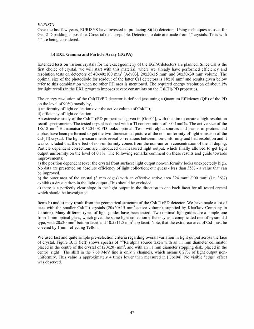
42
EURISYS Over the last few years, EURISYS have invested in producing Si(Li) detectors. Using techniques as used for Ge, 2-D padding is possible. Cross-talk is acceptable. Detectors to date are made from 4” crystals. Tests with 5” are being considered.
b) EXL Gamma and Particle Array (EGPA) Extended tests on various crystals for the exact geometry of the EGPA detectors are planned. Since CsI is the first choice of crystal, we will start with this material, where we already have performed efficiency and resolution tests on detectors of 40x40x100 mm3 [Adv03], 20x20x15 mm3 and 30x30x30 mm3 volume. The optimal size of the photodiode for readout of the latter CsI detectors is 18x18 mm2 and results given below refer to this combination when no other PD area is mentioned. The required energy resolution of about 1% for light recoils in the EXL program imposes severe constraints on the CsI(Tl)/PD properties. The energy resolution of the CsI(Tl)/PD detector is defined (assuming a Quantum Efficiency (QE) of the PD on the level of 90%) mostly by, i) uniformity of light collection over the active volume of CsI(Tl), ii) efficiency of light collection An extensive study of the CsI(Tl)/PD properties is given in [Goe04], with the aim to create a high-resolution recoil spectrometer. The tested crystal is doped with a Tl concentration of ~0.1mol%. The active size of the 18x18 mm2 Hamamatsu S-3204-08 PD looks optimal. Tests with alpha sources and beams of protons and alphas have been performed to get the two-dimensional picture of the non-uniformity of light emission of the CsI(Tl) crystal. The light measurements reveal correlations between non-uniformity and bad resolution and it was concluded that the effect of non-uniformity comes from the non-uniform concentration of the Tl doping. Particle dependent corrections are introduced on measured light output, which finally allowed to get light output uniformity on the level of 0.1%. The following remarks comment on these results and guide towards improvements: a) the position dependent (over the crystal front surface) light output non-uniformity looks unexpectedly high. No data are presented on absolute efficiency of light collection; our guess - less than 35% - a value that can be improved. b) the outer area of the crystal (3 mm edges) with an effective active area 324 mm2 /900 mm2 (i.e. 36%) exhibits a drastic drop in the light output. This should be excluded. c) there is a perfectly clear slope in the light output in the direction to one back facet for all tested crystal which should be investigated. Items b) and c) may result from the geometrical structure of the CsI(Tl)/PD detector. We have made a lot of tests with the smaller CsI(Tl) crystals (20x20x15 mm3 active volume), supplied by Khar'kov Company in Ukraine). Many different types of light guides have been tested. Two optimal lightguides are a simple one from 1 mm optical glass, which gives the same light collection efficiency as a complicated one of pyramidal type, with 20x20 mm2 bottom facet and 10.5x11.5 mm2 top facet. Note, that the extra rear area of CsI must be covered by 1 mm reflecting Teflon. We used fast and quite simple pre-selection criteria regarding overall variation in light output across the face of crystal. Figure B.15 (left) shows spectra of 226Ra alpha source taken with an 11 mm diameter collimator placed in the centre of the crystal of (20x20) mm2, and with an 11 mm diameter stopping disk, placed in the centre (right). The shift in the 7.68 MeV line is only 8 channels, which means 0.27% of light output non-uniformity. This value is approximately 4 times lower than measured in [Goe04]. No visible "edge" effect was observed.
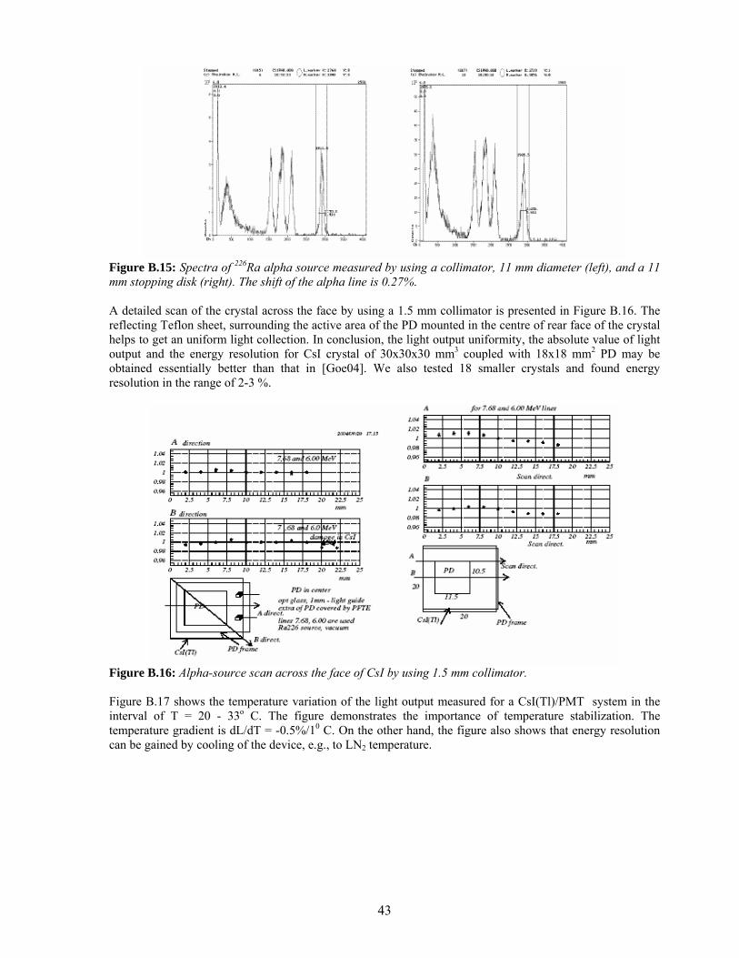
43
Figure B.15: Spectra of 226Ra alpha source measured by using a collimator, 11 mm diameter (left), and a 11 mm stopping disk (right). The shift of the alpha line is 0.27%. A detailed scan of the crystal across the face by using a 1.5 mm collimator is presented in Figure B.16. The reflecting Teflon sheet, surrounding the active area of the PD mounted in the centre of rear face of the crystal helps to get an uniform light collection. In conclusion, the light output uniformity, the absolute value of light output and the energy resolution for CsI crystal of 30x30x30 mm3 coupled with 18x18 mm2 PD may be obtained essentially better than that in [Goe04]. We also tested 18 smaller crystals and found energy resolution in the range of 2-3 %.
Figure B.16: Alpha-source scan across the face of CsI by using 1.5 mm collimator. Figure B.17 shows the temperature variation of the light output measured for a CsI(Tl)/PMT system in the interval of T = 20 - 33o C. The figure demonstrates the importance of temperature stabilization. The temperature gradient is dL/dT = -0.5%/10 C. On the other hand, the figure also shows that energy resolution can be gained by cooling of the device, e.g., to LN2 temperature.
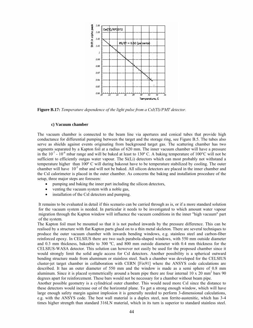
44
Figure B.17: Temperature dependence of the light pulse from a CsI(Tl)/PMT detector.
c) Vacuum chamber The vacuum chamber is connected to the beam line via apertures and conical tubes that provide high conductance for differential pumping between the target and the storage ring, see Figure B.5. The tubes also serve as shields against events originating from background target gas. The scattering chamber has two segments separated by a Kapton foil at a radius of 620 mm. The inner vacuum chamber will have a pressure in the 10-7 - 10-8 mbar range and will be baked at least to 130º C. A baking temperature of 100°C will not be sufficient to efficiently outgas water vapour. The Si(Li) detectors which can most probably not withstand a temperature higher than 100º C will during bakeout have to be temperature stabilized by cooling. The outer chamber will have 10-5 mbar and will not be baked. All silicon detectors are placed in the inner chamber and the CsI calorimeter is placed in the outer chamber. As concerns the baking and installation procedure of the setup, three major steps are foreseen:
• pumping and baking the inner part including the silicon detectors, • venting the vacuum system with a noble gas, • installation of the CsI detectors and pumping.
It remains to be evaluated in detail if this scenario can be carried through as is, or if a more standard solution for the vacuum system is needed. In particular it needs to be investigated to which amount water vapour migration through the Kapton window will influence the vacuum conditions in the inner "high vacuum" part of the system.
The Kapton foil must be mounted so that it is not pushed inwards by the pressure difference. This can be realised by a structure with flat Kapton parts glued on to a thin metal skeleton. There are several techniques to produce the outer vacuum chamber with inwards bending windows, e.g. stainless steel and carbon-fiber reinforced epoxy. In CELSIUS there are two such parabola-shaped windows, with 550 mm outside diameter and 0.3 mm thickness, bakeable to 300 ºC, and 800 mm outside diameter with 0.4 mm thickness for the CELSIUS-WASA detector. This solution can however not easily be used for the proposed chamber since it would strongly limit the solid angle access for CsI detectors. Another possibility is a spherical outward bending structure made from aluminum or stainless steel. Such a chamber was developed for the CELSIUS cluster-jet target chamber in collaboration with CERN [Fix91] where the ANSYS code calculations are described. It has an outer diameter of 550 mm and the window is made as a semi sphere of 0.8 mm aluminum. Since it is placed symmetrically around a beam pipe there are four internal 10 x 20 mm2 bars 90 degrees apart for reinforcement. These bars would not be necessary for a chamber without beam pipe. Another possible geometry is a cylindrical outer chamber. This would need more CsI since the distance to these detectors would increase out of the horizontal plane. To get a strong enough window, which will have large enough safety margin against implosion it is generally needed to perform 3-dimensional calculations, e.g. with the ANSYS code. The best wall material is a duplex steel, non ferrite-austenitic, which has 3-4 times higher strength than standard 316LN material, which in its turn is superior to standard stainless steel.
45
For further safety it could be possible to use curved external reinforcement bars mounted vertically to minimize the loss of solid angle for CsI detectors. As can bee seen from Figures B.5 and B.6, there is room available under the detector system for signal feedthroughs and for pumping of the chamber. Additional space for feedthroughs could possibly be fitted above the detectors close to the upper part of the cluster-jet target. To get access to the internal detector systems for mounting, cabling and service it is necessary to be able to open from at least one side. This should be possible for spherical and cylindrical geometry by using a gold wire seal. 1.4.5 Front-End Electronics
a) Overview of the design The number of channels that need to be coded for ESPA and EGPA is approximately 560,000 and 1,500 respectively. As will be noted below the pre-amplifier section of the front-end electronics will allow for the different devices, namely DSSD, Si(Li) and PD. The objective of this section is to present a considered option for the front-end electronics, which includes the ADCs and establish the different milestones for the various parts of the required R&D. For EXL the Si and Si(Li) detectors, together with part of the electronics, will be in UHV and the remainder in a lower vacuum. This causes difficulties associated with heat dissipation, access and feed-throughs. It is to be noted that there is a large number of channels to instrument in a comparatively small volume with a minimum of inactive volume. Thus the location of the electronics is crucial and it must be as compact as possible. The design challenges are:
• To minimise the power per channel (substantially below 1mW, ideally 200 µW in the front end). • To minimise the space required for electronics (hence use ASICs at the front end). • Cover a wide dynamic range (proton energies range from 0-100 MeV and it is necessary to start to
measure in the range of 100 keV). • Good position resolution (therefore many channels). • Accommodate both Si and Si(Li) detectors in the same ASIC. • Electronics and detectors must survive baking (up to 1300C). • Electronics and detectors must not contaminate the vacuum (no out-gasing or dirt).
The parameters to be measured are:
• Energy. • Position (implicit in x-y strip location). • Time (between a discriminator and an external reference timestamp or beam pulse in the range 0-100
or 0-200 ns with sub-ns precision). • Possibly also Pulse Shape Discrimination (PSD) (could be analogue or digital – the digital option
requires an analogue pipeline to achieve fast (GHz) sampling of the leading edge to be read out with the data – this is likely to be power-hungry and consume readout bandwidth, so analogue methods will also be investigated in the search for a lower power solution).
PSD is needed for the combination of E, T where the time-of-flight/energy plot does not allow for good distinction between protons, alphas etc. The extent of the need for PSD depends on the performance achieved in the timing and energy measurement parts.
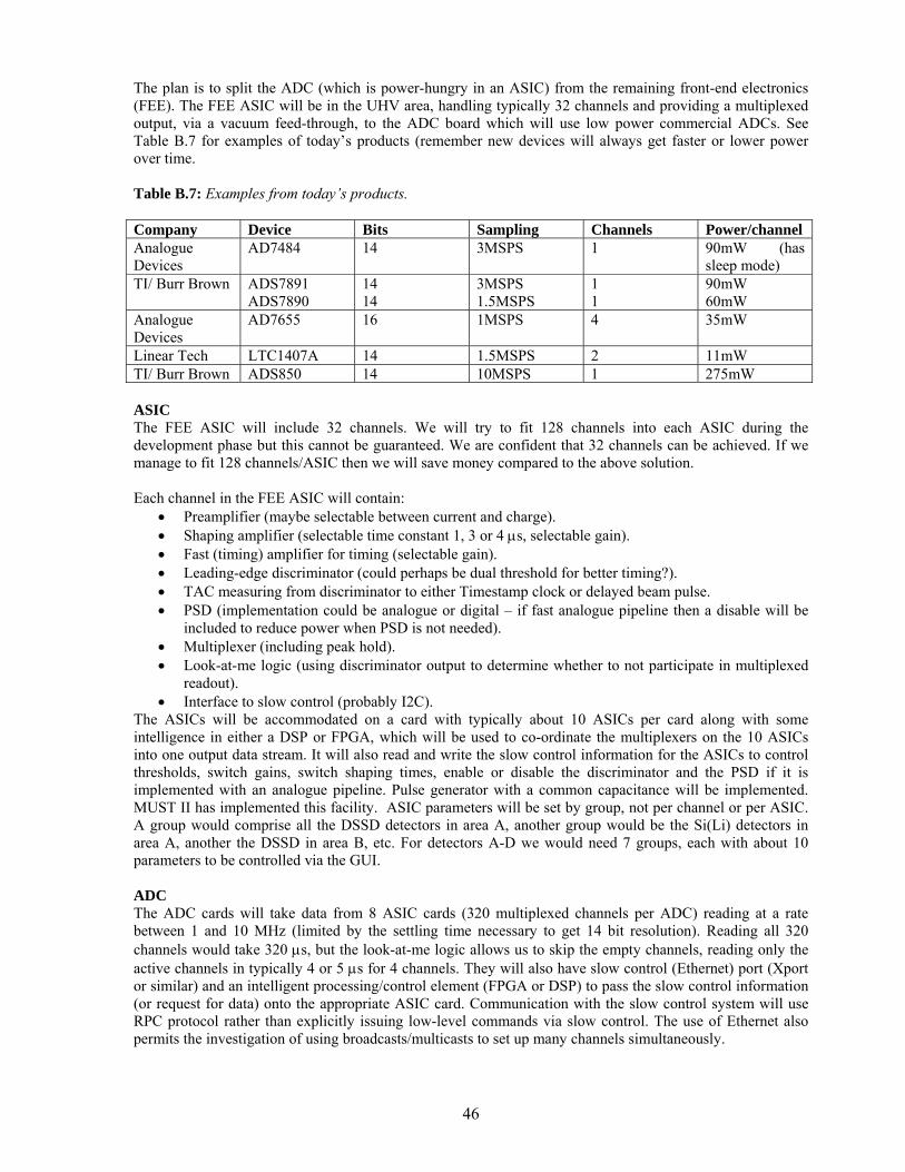
46
The plan is to split the ADC (which is power-hungry in an ASIC) from the remaining front-end electronics (FEE). The FEE ASIC will be in the UHV area, handling typically 32 channels and providing a multiplexed output, via a vacuum feed-through, to the ADC board which will use low power commercial ADCs. See Table B.7 for examples of today’s products (remember new devices will always get faster or lower power over time. Table B.7: Examples from today’s products. Company Device Bits Sampling Channels Power/channel Analogue Devices
AD7484 14 3MSPS 1 90mW (has sleep mode)
TI/ Burr Brown ADS7891 ADS7890
14 14
3MSPS 1.5MSPS
1 1
90mW 60mW
Analogue Devices
AD7655 16 1MSPS 4 35mW
Linear Tech LTC1407A 14 1.5MSPS 2 11mW TI/ Burr Brown ADS850 14 10MSPS 1 275mW ASIC The FEE ASIC will include 32 channels. We will try to fit 128 channels into each ASIC during the development phase but this cannot be guaranteed. We are confident that 32 channels can be achieved. If we manage to fit 128 channels/ASIC then we will save money compared to the above solution. Each channel in the FEE ASIC will contain:
• Preamplifier (maybe selectable between current and charge). • Shaping amplifier (selectable time constant 1, 3 or 4 µs, selectable gain). • Fast (timing) amplifier for timing (selectable gain). • Leading-edge discriminator (could perhaps be dual threshold for better timing?). • TAC measuring from discriminator to either Timestamp clock or delayed beam pulse. • PSD (implementation could be analogue or digital – if fast analogue pipeline then a disable will be
included to reduce power when PSD is not needed). • Multiplexer (including peak hold). • Look-at-me logic (using discriminator output to determine whether to not participate in multiplexed
readout). • Interface to slow control (probably I2C).
The ASICs will be accommodated on a card with typically about 10 ASICs per card along with some intelligence in either a DSP or FPGA, which will be used to co-ordinate the multiplexers on the 10 ASICs into one output data stream. It will also read and write the slow control information for the ASICs to control thresholds, switch gains, switch shaping times, enable or disable the discriminator and the PSD if it is implemented with an analogue pipeline. Pulse generator with a common capacitance will be implemented. MUST II has implemented this facility. ASIC parameters will be set by group, not per channel or per ASIC. A group would comprise all the DSSD detectors in area A, another group would be the Si(Li) detectors in area A, another the DSSD in area B, etc. For detectors A-D we would need 7 groups, each with about 10 parameters to be controlled via the GUI. ADC The ADC cards will take data from 8 ASIC cards (320 multiplexed channels per ADC) reading at a rate between 1 and 10 MHz (limited by the settling time necessary to get 14 bit resolution). Reading all 320 channels would take 320 µs, but the look-at-me logic allows us to skip the empty channels, reading only the active channels in typically 4 or 5 µs for 4 channels. They will also have slow control (Ethernet) port (Xport or similar) and an intelligent processing/control element (FPGA or DSP) to pass the slow control information (or request for data) onto the appropriate ASIC card. Communication with the slow control system will use RPC protocol rather than explicitly issuing low-level commands via slow control. The use of Ethernet also permits the investigation of using broadcasts/multicasts to set up many channels simultaneously.
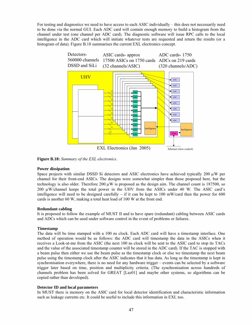
47
For testing and diagnostics we need to have access to each ASIC individually – this does not necessarily need to be done via the normal GUI. Each ADC card will contain enough memory to build a histogram from the channel under test (one channel per ADC card). The diagnostic software will issue RPC calls to the local intelligence in the ADC card which will initiate whatever tests are requested and return the results (or a histogram of data). Figure B.18 summarises the current EXL electronics concept.
Figure B.18: Summary of the EXL electronics. Power dissipation Space projects with similar DSSD Si detectors and ASIC electronics have achieved typically 200 µW per channel for their front-end ASICs. The designs were somewhat simpler than those proposed here, but the technology is also older. Therefore 200 µW is proposed as the design aim. The channel count is 187500, so 200 µW/channel keeps the total power in the UHV from the ASICs under 40 W. The ASIC card’s intelligence will need to be designed carefully – if it can be kept to 100 mW/card then the power for 600 cards is another 60 W, making a total heat load of 100 W at the front end.
Redundant cabling It is proposed to follow the example of MUST II and to have spare (redundant) cabling between ASIC cards and ADCs which can be used under software control in the event of problems or failures. Timestamp The data will be time stamped with a 100 ns clock. Each ADC card will have a timestamp interface. One method of operation would be as follows: the ADC card will timestamp the data in the ASICs when it receives a Look-at-me from the ASIC (the next 100 ns clock will be sent to the ASIC card to stop its TACs and the value of the associated timestamp counter will be stored in the ADC card). If the TAC is stopped with a beam pulse then either we use the beam pulse as the timestamp clock or else we timestamp the next beam pulse using the timestamp clock after the ASIC indicates that it has data. As long as the timestamp is kept in synchronisation everywhere, there is no need for any hardware trigger – events can be selected by a software trigger later based on time, position and multiplicity criteria. (The synchronisation across hundreds of channels problem has been solved for GREAT [Laz01] and maybe other systems, so algorithms can be copied rather than developed). Detector ID and local parameters In MUST there is memory on the ASIC card for local detector identification and characteristic information such as leakage currents etc. It could be useful to include this information in EXL too.
ASIC
Intelligence
ASIC
ASIC
ASIC
ASIC
ASIC
ASIC
ASIC
ASIC
ASIC
ASIC
Intelligence
ASIC
ASIC
ASIC
ASIC
ASIC
ASIC
ASIC
ASIC
ASIC
ASIC
Intelligence
ASIC
ASIC
ASIC
ASIC
ASIC
ASIC
ASIC
ASIC
ASIC
ASIC
Intelligence
ASIC
ASIC
ASIC
ASIC
ASIC
ASIC
ASIC
ASIC
ASIC
ASIC
Intelligence
ASIC
ASIC
ASIC
ASIC
ASIC
ASIC
ASIC
ASIC
ASIC
ASIC
Intelligence
ASIC
ASIC
ASIC
ASIC
ASIC
ASIC
ASIC
ASIC
ASIC
ASIC
Intelligence
ASIC
ASIC
ASIC
ASIC
ASIC
ASIC
ASIC
ASIC
ASIC
ASIC
Intelligence
ASIC
ASIC
ASIC
ASIC
ASIC
ASIC
ASIC
ASIC
ASIC
ASIC
Intelligence
ASIC
ASIC
ASIC
ASIC
ASIC
ASIC
ASIC
ASIC
ASIC
ASIC
Intelligence
ASIC
ASIC
ASIC
ASIC
ASIC
ASIC
ASIC
ASIC
ASIC
ASIC
Intelligence
ASIC
ASIC
ASIC
ASIC
ASIC
ASIC
ASIC
ASIC
ASIC
ASIC
Intelligence
ASIC
ASIC
ASIC
ASIC
ASIC
ASIC
ASIC
ASIC
ASIC
ASIC
Intelligence
ASIC
ASIC
ASIC
ASIC
ASIC
ASIC
ASIC
ASIC
ASIC
ASIC
Intelligence
ASIC
ASIC
ASIC
ASIC
ASIC
ASIC
ASIC
ASIC
ASIC
ASIC
Intelligence
ASIC
ASIC
ASIC
ASIC
ASIC
ASIC
ASIC
ASIC
ASIC
ASIC
Intelligence
ASIC
ASIC
ASIC
ASIC
ASIC
ASIC
ASIC
ASIC
ASIC
ADC
ADC
ADC
ADC
ADC
ADC
ADC
ADC
IntelligenceXPort
Ethernet (slow control)
Detectors-560000 channelsDSSD and SiLi
ASIC cards- approx17500 ASICs on 1750 cards(32 channels/ASIC)
ADC cards- 1750ADCs on 219 cards(320 channels/ADC)
EXL Electronics (Jan 2005)
UHV
32
32
32
32
32
32
32
32
32
32
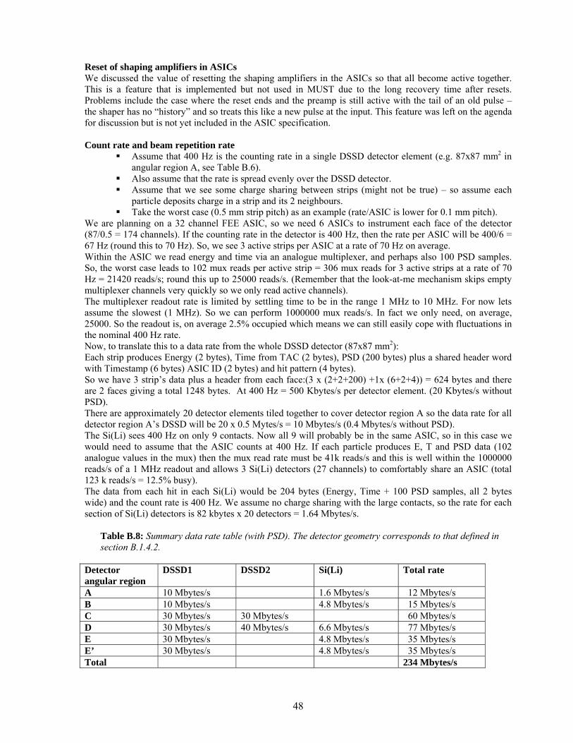
48
Reset of shaping amplifiers in ASICs We discussed the value of resetting the shaping amplifiers in the ASICs so that all become active together. This is a feature that is implemented but not used in MUST due to the long recovery time after resets. Problems include the case where the reset ends and the preamp is still active with the tail of an old pulse – the shaper has no “history” and so treats this like a new pulse at the input. This feature was left on the agenda for discussion but is not yet included in the ASIC specification.
Count rate and beam repetition rate
Assume that 400 Hz is the counting rate in a single DSSD detector element (e.g. 87x87 mm2 in angular region A, see Table B.6).
Also assume that the rate is spread evenly over the DSSD detector. Assume that we see some charge sharing between strips (might not be true) – so assume each
particle deposits charge in a strip and its 2 neighbours. Take the worst case (0.5 mm strip pitch) as an example (rate/ASIC is lower for 0.1 mm pitch).
We are planning on a 32 channel FEE ASIC, so we need 6 ASICs to instrument each face of the detector (87/0.5 = 174 channels). If the counting rate in the detector is 400 Hz, then the rate per ASIC will be 400/6 = 67 Hz (round this to 70 Hz). So, we see 3 active strips per ASIC at a rate of 70 Hz on average. Within the ASIC we read energy and time via an analogue multiplexer, and perhaps also 100 PSD samples. So, the worst case leads to 102 mux reads per active strip = 306 mux reads for 3 active strips at a rate of 70 Hz = 21420 reads/s; round this up to 25000 reads/s. (Remember that the look-at-me mechanism skips empty multiplexer channels very quickly so we only read active channels). The multiplexer readout rate is limited by settling time to be in the range 1 MHz to 10 MHz. For now lets assume the slowest (1 MHz). So we can perform 1000000 mux reads/s. In fact we only need, on average, 25000. So the readout is, on average 2.5% occupied which means we can still easily cope with fluctuations in the nominal 400 Hz rate. Now, to translate this to a data rate from the whole DSSD detector (87x87 mm2): Each strip produces Energy (2 bytes), Time from TAC (2 bytes), PSD (200 bytes) plus a shared header word with Timestamp (6 bytes) ASIC ID (2 bytes) and hit pattern (4 bytes). So we have 3 strip’s data plus a header from each face:(3 x (2+2+200) +1x (6+2+4)) = 624 bytes and there are 2 faces giving a total 1248 bytes. At 400 Hz = 500 Kbytes/s per detector element. (20 Kbytes/s without PSD). There are approximately 20 detector elements tiled together to cover detector region A so the data rate for all detector region A’s DSSD will be 20 x 0.5 Mytes/s = 10 Mbytes/s (0.4 Mbytes/s without PSD). The Si(Li) sees 400 Hz on only 9 contacts. Now all 9 will probably be in the same ASIC, so in this case we would need to assume that the ASIC counts at 400 Hz. If each particle produces E, T and PSD data (102 analogue values in the mux) then the mux read rate must be 41k reads/s and this is well within the 1000000 reads/s of a 1 MHz readout and allows 3 Si(Li) detectors (27 channels) to comfortably share an ASIC (total 123 k reads/s = 12.5% busy). The data from each hit in each Si(Li) would be 204 bytes (Energy, Time + 100 PSD samples, all 2 bytes wide) and the count rate is 400 Hz. We assume no charge sharing with the large contacts, so the rate for each section of Si(Li) detectors is 82 kbytes x 20 detectors = 1.64 Mbytes/s.
Table B.8: Summary data rate table (with PSD). The detector geometry corresponds to that defined in section B.1.4.2.
Detector angular region
DSSD1 DSSD2 Si(Li) Total rate
A 10 Mbytes/s 1.6 Mbytes/s 12 Mbytes/s B 10 Mbytes/s 4.8 Mbytes/s 15 Mbytes/s C 30 Mbytes/s 30 Mbytes/s 60 Mbytes/s D 30 Mbytes/s 40 Mbytes/s 6.6 Mbytes/s 77 Mbytes/s E 30 Mbytes/s 4.8 Mbytes/s 35 Mbytes/s E’ 30 Mbytes/s 4.8 Mbytes/s 35 Mbytes/s Total 234 Mbytes/s
49
Table B.8 is calculated based on each DSSD element (regardless of size and pitch) generating 0.5 Mbytes/s of data. So 20 elements = 10 Mbytes/s, 80 = 40 Mbytes/s, etc. For Si(Li) we assume 82 kbytes/element. The detector geometry is based on that defined in Table B.6. Synergies with DUBNA, SPIRAL II, Legnaro projects It is important to underline the importance of this R&D. The EXL program and thus the FEE to cope with 0.5 M channels is a significant project. Therefore it can spearhead and assemble the necessary funds and manpower for a generalised front-end device for multi-channel detection systems. It should be born in mind that for this synergy to be useful the labs of interest should make an active contribution in terms of ideas and manpower.
b) Time schedule and milestones ASIC:
Detailed ASIC specification: 12 months ASIC development: 12 months for 1st prototype, followed by 2 periods of 9 months (4 months testing, 3 months updating design, 2 months waiting for next prototype ASIC, preparing for tests) and then 6 months to test the final prototype before committing to full wafer run. Total= 12 months for spec and then 12 + 9 + 9 + 6 = 36 months for development (=48 months)
ASIC board:
Detailed specification: 2 months Circuit design: 2 months PCB design: 3 months Wait 2 months for assembly (no manpower needed) Test: 3 months Rework prototype (if necessary) 2 months Total elapsed time = 14 months
ADC board:
Detailed specification: 2 months Circuit design: 2 months PCB design: 3 months Wait 2 months for assembly (no manpower needed) Test: 3 months Rework prototype (if necessary) 2 months Total elapsed time = 14 months
Firmware for ADC and ASIC boards: 12 months.
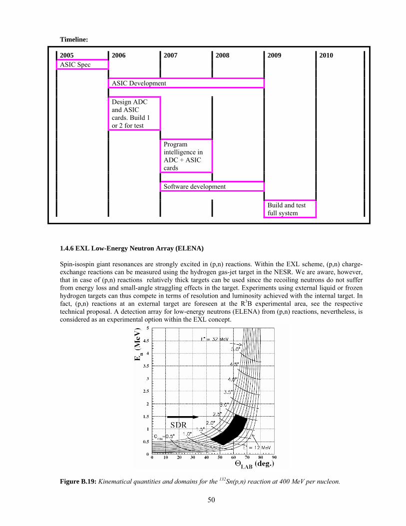
50
Timeline: 2005 2006 2007 2008 2009 2010 ASIC Spec ASIC Development Design ADC
and ASIC cards. Build 1 or 2 for test
Program
intelligence in ADC + ASIC cards
Software development Build and test
full system
1.4.6 EXL Low-Energy Neutron Array (ELENA) Spin-isospin giant resonances are strongly excited in (p,n) reactions. Within the EXL scheme, (p,n) charge-exchange reactions can be measured using the hydrogen gas-jet target in the NESR. We are aware, however, that in case of (p,n) reactions relatively thick targets can be used since the recoiling neutrons do not suffer from energy loss and small-angle straggling effects in the target. Experiments using external liquid or frozen hydrogen targets can thus compete in terms of resolution and luminosity achieved with the internal target. In fact, (p,n) reactions at an external target are foreseen at the R3B experimental area, see the respective technical proposal. A detection array for low-energy neutrons (ELENA) from (p,n) reactions, nevertheless, is considered as an experimental option within the EXL concept.
Figure B.19: Kinematical quantities and domains for the 132Sn(p,n) reaction at 400 MeV per nucleon.
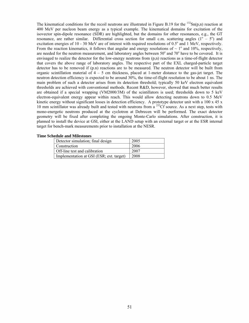
51
The kinematical conditions for the recoil neutrons are illustrated in Figure B.19 for the 132Sn(p,n) reaction at 400 MeV per nucleon beam energy as a typical example. The kinematical domains for excitation of the isovector spin-dipole resonance (SDR) are highlighted, but the domains for other resonances, e.g., the GT resonance, are rather similar. Differential cross section for small c.m. scattering angles (1o – 5o) and excitation energies of 10 - 30 MeV are of interest with required resolutions of 0.5o and 1 MeV, respectively. From the reaction kinematics, it follows that angular and energy resolutions of ~ 1o and 10%, respectively, are needed for the neutron measurement, and laboratory angles between 50o and 70o have to be covered. It is envisaged to realize the detector for the low-energy neutrons from (p,n) reactions as a time-of-flight detector that covers the above range of laboratory angles. The respective part of the EXL charged-particle target detector has to be removed if (p.n) reactions are to be measured. The neutron detector will be built from organic scintillation material of 4 – 5 cm thickness, placed at 1-meter distance to the gas-jet target. The neutron detection efficiency is expected to be around 30%, the time-of-flight resolution to be about 1 ns. The main problem of such a detector arises from its detection threshold; typically 50 keV electron equivalent thresholds are achieved with conventional methods. Recent R&D, however, showed that much better results are obtained if a special wrapping (VM2000/3M) of the scintillators is used; thresholds down to 5 keV electron-equivalent energy appear within reach. This would allow detecting neutrons down to 0.5 MeV kinetic energy without significant losses in detection efficiency. A prototype detector unit with a 100 x 45 x 10 mm scintillator was already built and tested with neutrons from a 252Cf source. As a next step, tests with mono-energetic neutrons produced at the cyclotron at Debrecen will be performed. The exact detector geometry will be fixed after completing the ongoing Monte-Carlo simulations. After construction, it is planned to install the device at GSI, either at the LAND setup with an external target or at the ESR internal target for bench-mark measurements prior to installation at the NESR. Time Schedule and Milestones
Detector simulation; final design 2005 Construction 2006 Off-line test and calibration 2007 Implementation at GSI (ESR; ext. target) 2008
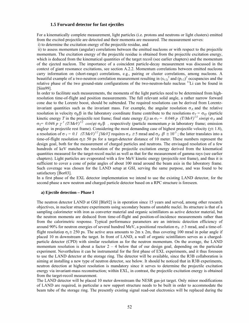
52
1.5 Forward detector for fast ejectiles For a kinematically complete measurement, light particles (i.e. protons and neutrons or light clusters) emitted from the excited projectile are detected and their momenta are measured. The measurement serves: i) to determine the excitation energy of the projectile residue, and ii) to assess momentum (angular) correlations between the emitted nucleons or with respect to the projectile momentum. The excitation energy of the projectile residue is obtained from the projectile excitation energy, which is deduced from the kinematical quantities of the target recoil (see earlier chapters) and the momentum of the ejected nucleon. The importance of a coincident particle-decay measurement was discussed in the context of giant resonance excitations, see section A.2.2. Momentum correlations between emitted nucleons carry information on (short-range) correlations, e.g., pairing or cluster correlations, among nucleons. A beautiful example of a two-neutron correlation measurement resulting in (s1/2)
2 and (p1/2)2 occupancies and the relative phase of the two ground-state configurations of the two-neutron-halo nucleus 11Li can be found in [Sim99]. In order to facilitate such measurements, the momenta of the light particles need to be determined from high-resolution time-of-flight and position measurements. The full relevant solid angle, a rather narrow forward cone due to the Lorentz boost, should be subtended. The required resolutions can be derived from Lorentz-invariant quantities such as the invariant mass. For example, the angular resolution σϑ and the relative resolution in velocity σβ/ β in the laboratory coordinate frame contribute to the resolutions σT = σEf (particle kinetic energy T in the projectile rest frame; final state energy Ef) as σT = 0.046 p (T/MeV)1/2 sin(ϕ ) σϑ and σT= 0.046 p γ 3 (T/MeV)1/2 cos(ϕ) σβ/β , respectively (particle momentum p in laboratory frame; emission angleϕ in projectile rest frame). Considering the most demanding case of highest projectile velocity (γ ≅ 1.8), a resolution of σ T = 0.1 (T/MeV)1/2 [MeV] requires σϑ ≅ 5 mrad and σβ /β ≅ 10-3 ; the latter translates into a time-of-flight resolution σt ≅ 50 ps for a target-detector distance of 10 meter. These numbers represent the design goal, both for the measurement of charged particles and neutrons. The envisaged resolution of a few hundreds of keV matches the resolution of the projectile excitation energy derived from the kinematical quantities measured for the target-recoil nuclei as well as that for the measurement of gamma rays (see earlier chapters). Light particles are evaporated with a few MeV kinetic energy (projectile rest frame), and thus it is sufficient to cover a cone of polar angles of about 100 mrad around the beam axis in the laboratory frame. Such coverage was chosen for the LAND setup at GSI, serving the same purpose, and was found to be satisfactory [Bor03]. In a first phase of the EXL detector implementation we intend to use the existing LAND detector, for the second phase a new neutron and charged particle detector based on a RPC structure is foreseen. a) Ejectile detection – Phase I The neutron detector LAND at GSI [Bla92] is in operation since 15 years and served, among other research objectives, in nuclear structure experiments using secondary beams of unstable nuclei. Its structure is that of a sampling calorimeter with iron as converter material and organic scintillators as active detector material, but the neutron momenta are deduced from time-of-flight and position-of-incidence measurements rather than from the calorimetric response. Typical performance parameters are an intrinsic detection efficiency of around 90% for neutron energies of several hundred MeV, a positional resolution σϑ ≅ 3 mrad, and a time-of-flight resolution σt ≅ 250 ps. The active area amounts to 2m x 2m, thus covering 100 mrad in polar angle if placed 10 m downstream the target. In front of LAND, a wall of organic scintillators serves as a charged-particle detector (CPD) with similar resolution as for the neutron momentum. On the average, the LAND momentum resolution is about a factor 2 – 4 below that of our design goal, depending on the particular experiment. Nevertheless it can be instrumental for the first phase of EXL experiments, and it thus foreseen to use the LAND detector at the storage ring. The detector will be available, since the R3B collaboration is aiming at installing a new type of neutron detector, see below. It should be noticed that in R3B experiments, neutron detection at highest resolution is mandatory since it serves to determine the projectile excitation energy via invariant-mass reconstruction; within EXL, in contrast, the projectile excitation energy is obtained from the target-recoil measurement. The LAND detector will be placed 10 meter downstream the NESR gas-jet target. Only minor modifications of LAND are required, in particular a new support structure needs to be built in order to accommodate the beam tube of the storage ring. The presently existing signal read-out electronics will be replaced during the
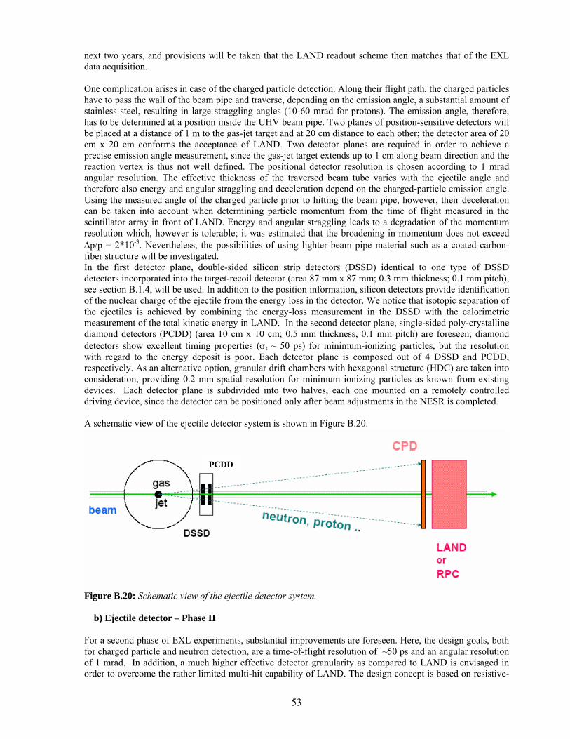
53
next two years, and provisions will be taken that the LAND readout scheme then matches that of the EXL data acquisition. One complication arises in case of the charged particle detection. Along their flight path, the charged particles have to pass the wall of the beam pipe and traverse, depending on the emission angle, a substantial amount of stainless steel, resulting in large straggling angles (10-60 mrad for protons). The emission angle, therefore, has to be determined at a position inside the UHV beam pipe. Two planes of position-sensitive detectors will be placed at a distance of 1 m to the gas-jet target and at 20 cm distance to each other; the detector area of 20 cm x 20 cm conforms the acceptance of LAND. Two detector planes are required in order to achieve a precise emission angle measurement, since the gas-jet target extends up to 1 cm along beam direction and the reaction vertex is thus not well defined. The positional detector resolution is chosen according to 1 mrad angular resolution. The effective thickness of the traversed beam tube varies with the ejectile angle and therefore also energy and angular straggling and deceleration depend on the charged-particle emission angle. Using the measured angle of the charged particle prior to hitting the beam pipe, however, their deceleration can be taken into account when determining particle momentum from the time of flight measured in the scintillator array in front of LAND. Energy and angular straggling leads to a degradation of the momentum resolution which, however is tolerable; it was estimated that the broadening in momentum does not exceed ∆p/p = 2*10-3. Nevertheless, the possibilities of using lighter beam pipe material such as a coated carbon-fiber structure will be investigated. In the first detector plane, double-sided silicon strip detectors (DSSD) identical to one type of DSSD detectors incorporated into the target-recoil detector (area 87 mm x 87 mm; 0.3 mm thickness; 0.1 mm pitch), see section B.1.4, will be used. In addition to the position information, silicon detectors provide identification of the nuclear charge of the ejectile from the energy loss in the detector. We notice that isotopic separation of the ejectiles is achieved by combining the energy-loss measurement in the DSSD with the calorimetric measurement of the total kinetic energy in LAND. In the second detector plane, single-sided poly-crystalline diamond detectors (PCDD) (area 10 cm x 10 cm; 0.5 mm thickness, 0.1 mm pitch) are foreseen; diamond detectors show excellent timing properties (σt ~ 50 ps) for minimum-ionizing particles, but the resolution with regard to the energy deposit is poor. Each detector plane is composed out of 4 DSSD and PCDD, respectively. As an alternative option, granular drift chambers with hexagonal structure (HDC) are taken into consideration, providing 0.2 mm spatial resolution for minimum ionizing particles as known from existing devices. Each detector plane is subdivided into two halves, each one mounted on a remotely controlled driving device, since the detector can be positioned only after beam adjustments in the NESR is completed. A schematic view of the ejectile detector system is shown in Figure B.20.
Figure B.20: Schematic view of the ejectile detector system. b) Ejectile detector – Phase II For a second phase of EXL experiments, substantial improvements are foreseen. Here, the design goals, both for charged particle and neutron detection, are a time-of-flight resolution of ~50 ps and an angular resolution of 1 mrad. In addition, a much higher effective detector granularity as compared to LAND is envisaged in order to overcome the rather limited multi-hit capability of LAND. The design concept is based on resistive-
PCDD
54
plate chambers, in case of neutron detection combined with converter material where neutrons induce hadronic showers. The development of this new type of detector is performed in a joint R3B and EXL collaboration, see the R3B technical proposal. Introductory remarks. Resistive Plate Chambers (RPC) are detectors for ionizing particles and presently, these types of detectors are used in many different experiments at particle accelerators or in cosmic-ray studies such as in the STAR, RICK, CMS and ATLAS experiments at LHC, CERN, AGRO etc. [RPC04]. Excellent time resolutions down to below 50 ps [Fon00] were achieved for minimum ionizing particles using multigap resistive plate chambers (MRPC), introduced by [Cer96]. Building of large detector arrays with high granularity is feasible, thus RPC detection concepts partly take over the classical application of (organic) scintillators arrays. A. Blanco et al. [Bla02] showed that a large area MRPC (160 cm ×10 cm, 2 strip readout), in addition to an efficiency for minimum ionizing particles of more than 95%, could provide good time resolutions of σt ~ 50-70 ps and a position resolution of 1.2 cm along the read-out strips using time the difference method. With the impressing time resolutions accompanied by good positional resolutions using either a strip readout, pad readout, or using the granularity of the system, MRPC appear to be ideally suited for the detection of the charged particles also of the hadronic shower induced by neutrons. Improved resolution should also allow for a much improved tracking of the induced hadronic shower and thus for a more efficient multi-hit resolving power. A neutron detector concept based upon RPC is investigated in the following. Neutron detection with RPC. A sandwich structure of converter material (iron, tungsten) and RPC arrays is considered. Exemplarily, a detector is visualized with 2×2 m2 active area and about 0.8 m depth formed from alternating layers of iron converter of 1 cm thickness followed by arrays of RPC built up from modules of 100×3 cm2 with a depth of ~1.1 cm, arranging 2×67 modules to cover the active area. With stacking of 35 of these combined converter/RPC structures, the depth of the detector material corresponds to more than 3 interaction lengths (~17.8 (33) cm for Fe (RPC materials)) in order to provide a detection efficiency for fast neutrons of more than 90%. The time signals induced by a hadronic shower particle are taken from the anode for both far sides of the RPC chambers, thus allowing for mean timing information and for position information within the length of the chamber via the time-difference method. The position of the hit in the two additional dimensions is obtained from the granularity of the detector system, i.e. by the width of the RPC chambers (3cm) and the depth of the converter/RPC structures (2-3 cm), respectively, leading to resolutions of σy,z ≈1 cm. This example amounts to a total number of 4690 RPC chambers (35 planes, 2×67 RPC per plane) and a number of 9380 signals to be read out. The active area covered by RPC sums up to 140 m2. Alternatively a width of the RPC chambers of about 10 cm is considered, using multi-strip anodes to obtain the position resolution, leading to about 1600 RPC chambers needed for the neutron detector. According to our knowledge, up to now, no explicit experimental studies exist for the response of RPC detectors to high energy neutrons (50-1000 MeV) and the charged particles produced from the neutron induced reactions.. For the neutron sensitivity of a double gap RPC, simulations were performed over a wide neutron energy range [Alt01]. Experimental neutron sensitivity data only exist for neutrons with 2 and 20 MeV in agreement with the simulation [Abb03]. Therefore, extensive studies comprising test experiments using RPC prototypes and detailed simulations of the RPC performance for neutrons, respectively protons, with energies from 50-1000 MeV will be carried out within the next two years. The simulations will comprise i) studies of the neutron induced shower production allowing for optimizations on the geometrical design using transport codes such as GEANT in combination with FLUKA [FLUKA] and ii) studies of the intrinsic time response for MRPC, allowing for optimizations of dimensions and type of resistive plates, number of gaps, gas mixtures etc. Monte-Carlo model calculations exist for the avalanche development considering space charge effects [Fon00b,Rie03], also analytical calculations exist [Man04]. For the geometrical design of the RPC we have to take into account mechanical stability, different readout schemes, multi-hit capabilities, chamber size versus number of readout channels etc. Additionally, possibilities using the RPC structure as a supplementary neutron converter have to be investigated, i.e., a double-stack multi-gap RPC with an increased thickness of the anode is conceivable, using this anode as an additional converter material. Finally, we notice that charged particle detection (see discussion in section 'phase I') can easily be accomplished by installing a plane of RPC modules without converter material in front of the neutron detector.
55
Radiation hardness. The detectors will be used for experiments with radioactive beams circulating in the NESR, expected luminosities are of the order of 1028 cm-2 s-1. With reaction cross sections of the order of barn, the number of neutrons and protons emitted from the projectile amounts to about 5*104/s. With a running time of 2 months per year, 2.5*1011 ejectiles (protons and neutrons) per year will be deposited in the detector volume, neglecting a duty cycle. RPC are widely used in high-energy physics, where rates/cm2 are usually up to 5 orders of magnitude larger than in our experiments (typically 0.1 Hz/cm2). Therefore radiation hardness of the RPC neutron detector is not critical, nevertheless in the following we give an evaluation on the effect of the dosis on the neutron detector. The 2.5*1011 neutrons/year hitting the detector translate into 5*106 ejectiles/cm2/year assuming 3 RPC counts per neutron hit. Aging effects for RPC are evaluated by the total charge flow across the detector during its lifetime, assuming an average avalanche charge of 10 pC, the total charge integrated over a period of 10 years amounts to about 0.5 mC. Recent studies for MRPC operated in the avalanche mode showed no aging effects up to 10 mC/cm2 [Aki04] and even for 800 mC/cm2 [Lop04]. Space requirements. The active size of the neutron detector will cover, similarly to the existing LAND, 2*2 m2 area, the active depth depending on the detailed structure of the detector will not exhaust 2 m (1m actually foreseen). The detector surrounds the NESR beam transport line at a distance of 10-12 meter downstream the gas-jet target. Along the distance between target and the neutron detector, installations other than required by the experiment, which would hinder the free passage of the neutrons and charged particles cannot be accepted. Including the support structures, the outer dimensions of the neutron detector should not exceed 4*3 m2 on the floor with a height of 4m, additional space is needed for electronic racks, power supply, cooling and possibly gas supply, we assume 30 m2. Test experiments. During the next two years, test experiments are indispensable, in order to investigate the response to fast neutrons (respectively to their products) for RPC detectors. The maximum achievable time resolution has to be determined, depending on detector size and geometry. Therefore, proton beams with energies of 50-1000 MeV are necessary, as turned out in the simulations, and for the prototype tests, neutron beams of 200-1000 MeV, produced from deuteron and triton break up. Calibration. After having set up the neutron detector, one calibration run is needed using tagged neutrons from the deuteron (and triton) breakup varying the beam energy in the range of 200 to 1000 MeV to investigate in detail the neutron efficiency and the neutron response behaviour for one- and multi-neutron hits. The time adjustment of the modular detector system can, as it is done for LAND, be performed by tracking cosmic rays passing the detector volume. Time Schedule and Milestones Substantial technical development work is required for the RPC neutron detector only. 2005-2006 Detector tests (prototype neutron RPC)
Simulations of the performance of the fully integrated ejectile detector system
End of 2006 Final decision on RPC detector structure 2007 Production and test of one RPC layer 2008-2010 Production, installation, test, commissioning
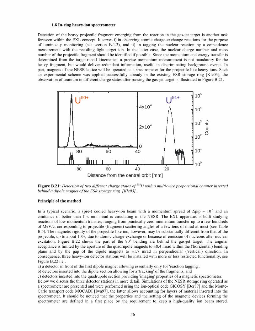
56
1.6 In-ring heavy-ion spectrometer Detection of the heavy projectile fragment emerging from the reaction in the gas-jet target is another task foreseen within the EXL concept. It serves i) in observing atomic charge-exchange reactions for the purpose of luminosity monitoring (see section B.1.3), and ii) in tagging the nuclear reaction by a coincidence measurement with the recoiling light target ion. In the latter case, the nuclear charge number and mass number of the projectile fragment should be identified if possible. Since the momentum and energy transfer is determined from the target-recoil kinematics, a precise momentum measurement is not mandatory for the heavy fragment, but would deliver redundant information, useful in discriminating background events. In part, magnets of the NESR lattice will be operated as a spectrometer for the projectile-like heavy ions. Such an experimental scheme was applied successfully already in the existing ESR storage ring [Kle03]; the observation of uranium in different charge states after passing the gas-jet target is illustrated in Figure B.21.
80 60 40 20100
101
102
103
104
105
80 60 400
2x10⁴
4x10⁴
U90+
Cou
nts
U91+
Distance from the central orbit [mm] Figure B.21: Detection of two different charge states of 238U with a multi-wire proportional counter inserted behind a dipole magnet of the ESR storage ring [Kle03]. Principle of the method In a typical scenario, a (pre-) cooled heavy-ion beam with a momentum spread of ∆p/p ~ 10-4 and an emittance of better than 1 π mm mrad is circulating in the NESR. The EXL apparatus is built studying reactions of low momentum transfer, ranging from practically zero momentum transfer up to a few hundreds of MeV/c, corresponding to projectile (fragment) scattering angles of a few tens of mrad at most (see Table B.5). The magnetic rigidity of the projectile-like ion, however, may be substantially different from that of the projectile, up to about 10%, due to atomic charge-exchange or because of emission of nucleons after nuclear excitation. Figure B.22 shows the part of the 90o bending arc behind the gas-jet target. The angular acceptance is limited by the aperture of the quadrupole magnets to ±8.4 mrad within the ('horizontal') bending plane and by the gap of the dipole magnets to ±1.7 mrad in perpendicular ('vertical') direction. In consequence, three heavy-ion detector stations will be installed with more or less restricted functionality, see Figure B.22 i.e., a) a detector in front of the first dipole magnet allowing essentially only for 'reaction tagging', b) detectors inserted into the dipole section allowing for a 'tracking' of the fragments, and c) detectors inserted into the quadrupole section providing 'imaging' properties of a magnetic spectrometer. Below we discuss the three detector stations in more detail. Simulations of the NESR storage ring operated as a spectrometer are presented and were performed using the ion-optical code GICOSY [Ber87] and the Monte-Carlo transport code MOCADI [Iwa97], the latter allows accounting for layers of material inserted into the spectrometer. It should be noticed that the properties and the setting of the magnetic devices forming the spectrometer are defined in a first place by the requirement to keep a high-quality ion beam stored.
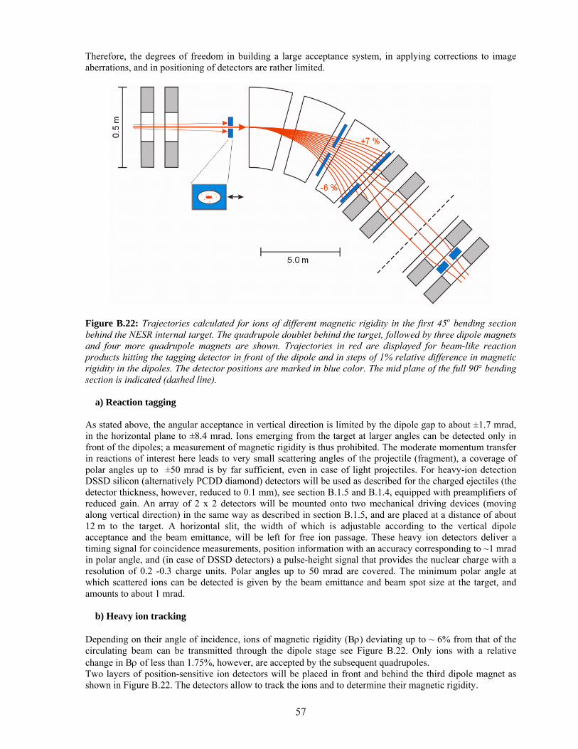
57
Therefore, the degrees of freedom in building a large acceptance system, in applying corrections to image aberrations, and in positioning of detectors are rather limited.
Figure B.22: Trajectories calculated for ions of different magnetic rigidity in the first 45o bending section behind the NESR internal target. The quadrupole doublet behind the target, followed by three dipole magnets and four more quadrupole magnets are shown. Trajectories in red are displayed for beam-like reaction products hitting the tagging detector in front of the dipole and in steps of 1% relative difference in magnetic rigidity in the dipoles. The detector positions are marked in blue color. The mid plane of the full 90° bending section is indicated (dashed line). a) Reaction tagging As stated above, the angular acceptance in vertical direction is limited by the dipole gap to about ±1.7 mrad, in the horizontal plane to ±8.4 mrad. Ions emerging from the target at larger angles can be detected only in front of the dipoles; a measurement of magnetic rigidity is thus prohibited. The moderate momentum transfer in reactions of interest here leads to very small scattering angles of the projectile (fragment), a coverage of polar angles up to ±50 mrad is by far sufficient, even in case of light projectiles. For heavy-ion detection DSSD silicon (alternatively PCDD diamond) detectors will be used as described for the charged ejectiles (the detector thickness, however, reduced to 0.1 mm), see section B.1.5 and B.1.4, equipped with preamplifiers of reduced gain. An array of 2 x 2 detectors will be mounted onto two mechanical driving devices (moving along vertical direction) in the same way as described in section B.1.5, and are placed at a distance of about 12 m to the target. A horizontal slit, the width of which is adjustable according to the vertical dipole acceptance and the beam emittance, will be left for free ion passage. These heavy ion detectors deliver a timing signal for coincidence measurements, position information with an accuracy corresponding to ~1 mrad in polar angle, and (in case of DSSD detectors) a pulse-height signal that provides the nuclear charge with a resolution of 0.2 -0.3 charge units. Polar angles up to 50 mrad are covered. The minimum polar angle at which scattered ions can be detected is given by the beam emittance and beam spot size at the target, and amounts to about 1 mrad. b) Heavy ion tracking Depending on their angle of incidence, ions of magnetic rigidity (Bρ) deviating up to ~ 6% from that of the circulating beam can be transmitted through the dipole stage see Figure B.22. Only ions with a relative change in Bρ of less than 1.75%, however, are accepted by the subsequent quadrupoles. Two layers of position-sensitive ion detectors will be placed in front and behind the third dipole magnet as shown in Figure B.22. The detectors allow to track the ions and to determine their magnetic rigidity.
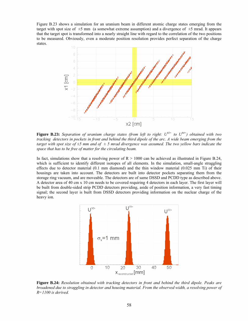
58
Figure B.23 shows a simulation for an uranium beam in different atomic charge states emerging from the target with spot size of ±5 mm (a somewhat extreme assumption) and a divergence of ±5 mrad. It appears that the target spot is transformed into a nearly straight line with regard to the correlation of the two positions to be measured. Obviously, even a moderate position resolution provides perfect separation of the charge states.
Figure B.23: Separation of uranium charge states (from left to right: U92+ to U84+) obtained with two tracking detectors in pockets in front and behind the third dipole of the arc. A wide beam emerging from the target with spot size of ±5 mm and of ± 5 mrad divergence was assumed. The two yellow bars indicate the space that has to be free of matter for the circulating beam. In fact, simulations show that a resolving power of R > 1000 can be achieved as illustrated in Figure B.24, which is sufficient to identify different isotopes of all elements. In the simulation, small-angle straggling effects due to detector material (0.1 mm diamond) and the thin window material (0.025 mm Ti) of their housings are taken into account. The detectors are built into detector pockets separating them from the storage ring vacuum, and are moveable. The detectors are of same DSSD and PCDD type as described above. A detector area of 40 cm x 10 cm needs to be covered requiring 4 detectors in each layer. The first layer will be built from double-sided strip PCDD detectors providing, aside of position information, a very fast timing signal; the second layer is built from DSSD detectors providing information on the nuclear charge of the heavy ion.
Figure B.24: Resolution obtained with tracking detectors in front and behind the third dipole. Peaks are broadened due to straggling in detector and housing material. From the observed width, a resolving power of R=1100 is derived.
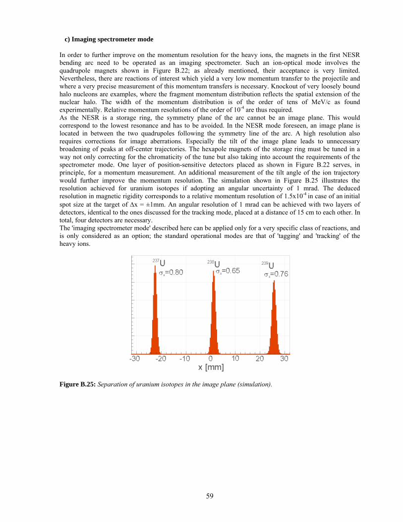
59
c) Imaging spectrometer mode In order to further improve on the momentum resolution for the heavy ions, the magnets in the first NESR bending arc need to be operated as an imaging spectrometer. Such an ion-optical mode involves the quadrupole magnets shown in Figure B.22; as already mentioned, their acceptance is very limited. Nevertheless, there are reactions of interest which yield a very low momentum transfer to the projectile and where a very precise measurement of this momentum transfers is necessary. Knockout of very loosely bound halo nucleons are examples, where the fragment momentum distribution reflects the spatial extension of the nuclear halo. The width of the momentum distribution is of the order of tens of MeV/c as found experimentally. Relative momentum resolutions of the order of 10-4 are thus required. As the NESR is a storage ring, the symmetry plane of the arc cannot be an image plane. This would correspond to the lowest resonance and has to be avoided. In the NESR mode foreseen, an image plane is located in between the two quadrupoles following the symmetry line of the arc. A high resolution also requires corrections for image aberrations. Especially the tilt of the image plane leads to unnecessary broadening of peaks at off-center trajectories. The hexapole magnets of the storage ring must be tuned in a way not only correcting for the chromaticity of the tune but also taking into account the requirements of the spectrometer mode. One layer of position-sensitive detectors placed as shown in Figure B.22 serves, in principle, for a momentum measurement. An additional measurement of the tilt angle of the ion trajectory would further improve the momentum resolution. The simulation shown in Figure B.25 illustrates the resolution achieved for uranium isotopes if adopting an angular uncertainty of 1 mrad. The deduced resolution in magnetic rigidity corresponds to a relative momentum resolution of 1.5x10⁻⁴ in case of an initial spot size at the target of ∆x = ±1mm. An angular resolution of 1 mrad can be achieved with two layers of detectors, identical to the ones discussed for the tracking mode, placed at a distance of 15 cm to each other. In total, four detectors are necessary. The 'imaging spectrometer mode' described here can be applied only for a very specific class of reactions, and is only considered as an option; the standard operational modes are that of 'tagging' and 'tracking' of the heavy ions.
Figure B.25: Separation of uranium isotopes in the image plane (simulation).
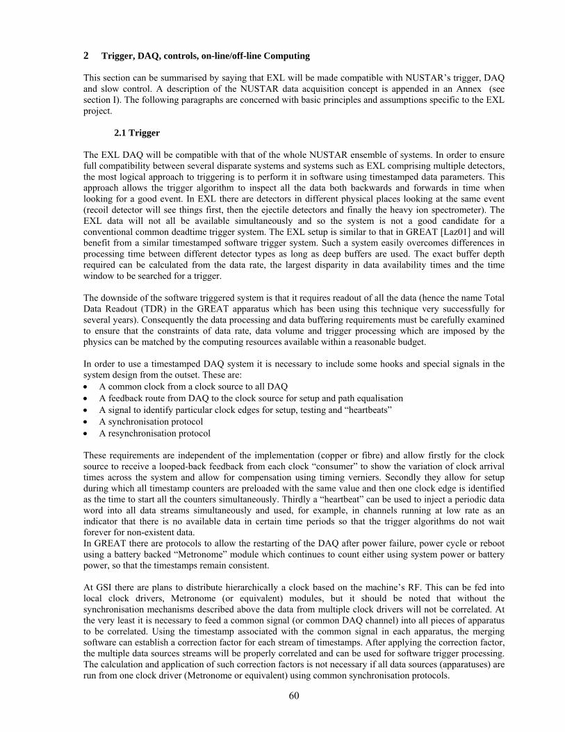
60
2 Trigger, DAQ, controls, on-line/off-line Computing
This section can be summarised by saying that EXL will be made compatible with NUSTAR’s trigger, DAQ and slow control. A description of the NUSTAR data acquisition concept is appended in an Annex (see section I). The following paragraphs are concerned with basic principles and assumptions specific to the EXL project.
2.1 Trigger
The EXL DAQ will be compatible with that of the whole NUSTAR ensemble of systems. In order to ensure full compatibility between several disparate systems and systems such as EXL comprising multiple detectors, the most logical approach to triggering is to perform it in software using timestamped data parameters. This approach allows the trigger algorithm to inspect all the data both backwards and forwards in time when looking for a good event. In EXL there are detectors in different physical places looking at the same event (recoil detector will see things first, then the ejectile detectors and finally the heavy ion spectrometer). The EXL data will not all be available simultaneously and so the system is not a good candidate for a conventional common deadtime trigger system. The EXL setup is similar to that in GREAT [Laz01] and will benefit from a similar timestamped software trigger system. Such a system easily overcomes differences in processing time between different detector types as long as deep buffers are used. The exact buffer depth required can be calculated from the data rate, the largest disparity in data availability times and the time window to be searched for a trigger. The downside of the software triggered system is that it requires readout of all the data (hence the name Total Data Readout (TDR) in the GREAT apparatus which has been using this technique very successfully for several years). Consequently the data processing and data buffering requirements must be carefully examined to ensure that the constraints of data rate, data volume and trigger processing which are imposed by the physics can be matched by the computing resources available within a reasonable budget. In order to use a timestamped DAQ system it is necessary to include some hooks and special signals in the system design from the outset. These are: • A common clock from a clock source to all DAQ • A feedback route from DAQ to the clock source for setup and path equalisation • A signal to identify particular clock edges for setup, testing and “heartbeats” • A synchronisation protocol • A resynchronisation protocol These requirements are independent of the implementation (copper or fibre) and allow firstly for the clock source to receive a looped-back feedback from each clock “consumer” to show the variation of clock arrival times across the system and allow for compensation using timing verniers. Secondly they allow for setup during which all timestamp counters are preloaded with the same value and then one clock edge is identified as the time to start all the counters simultaneously. Thirdly a “heartbeat” can be used to inject a periodic data word into all data streams simultaneously and used, for example, in channels running at low rate as an indicator that there is no available data in certain time periods so that the trigger algorithms do not wait forever for non-existent data. In GREAT there are protocols to allow the restarting of the DAQ after power failure, power cycle or reboot using a battery backed “Metronome” module which continues to count either using system power or battery power, so that the timestamps remain consistent. At GSI there are plans to distribute hierarchically a clock based on the machine’s RF. This can be fed into local clock drivers, Metronome (or equivalent) modules, but it should be noted that without the synchronisation mechanisms described above the data from multiple clock drivers will not be correlated. At the very least it is necessary to feed a common signal (or common DAQ channel) into all pieces of apparatus to be correlated. Using the timestamp associated with the common signal in each apparatus, the merging software can establish a correction factor for each stream of timestamps. After applying the correction factor, the multiple data sources streams will be properly correlated and can be used for software trigger processing. The calculation and application of such correction factors is not necessary if all data sources (apparatuses) are run from one clock driver (Metronome or equivalent) using common synchronisation protocols.
61
The only deadtime in a system such as that described here is from the pileup in the front end acquisition channels at the signal processing stage (this applies both to analogue processing and digital processing front ends). There is no deadtime associated with trigger processing. The conventional “interlocked trigger” methods used in many existing setups have the drawback that while waiting for the slowest part of a potential trigger, they are dead to new events (one of which might actually be much more significant than the event which is occupying the system). Such a method of operation should not be considered for new apparatus although it will be necessary to timestamp and accept trigger signals (identified by event numbers) from such conventional systems to maintain compatibility with existing equipment. The GREAT pattern unit (or an equivalent) associates a timestamp with an input logic pulse (e.g. a trigger pulse and part of an event number from existing equipment). Although examples are given here from the GREAT TDR system [Laz01], other people have also implemented or are implementing similar solutions: the GSI TITRIS concept is similar as is the CENTRUM built by GANIL and also the AGATA GTS mechanism.
2.2 DAQ The DAQ needs to have common data interface ports (again these should be defined to be compatible with NUSTAR requirements). This applies to physical connections, but is much more important at the data format level. So, for example, each data stream should be sent over some agreed network link (e.g. 10Gbit Ethernet fibre?) using an agreed format. The physical link allows economy of scale by using common hardware but hardware compatibility is not essential. For example there could be several different physical interfaces placing data in memory accessible over one bus. In this case the memory becomes the interface port (c.f. RISING). However, if multiple data formats are used then the DAQ software must waste time converting the many formats into one- where possible this waste of computing resources should be avoided. Therefore a standard data format should be defined for NUSTAR and will be used by EXL data producers when they transmit their data streams. The preceding paragraph assumes that the data producers “push” the data into the DAQ computing rather than the data consumers “pulling” the data. As long as processing power matches or exceeds the requirements imposed by the trigger/tracing/event building algorithms and data rates and also that there is sufficient buffering to cope with short term fluctuations, then the push/pull question can be resolved either way. But if a flow control mechanism is required then the data consumers must authorise the transfers from the front end (either explicitly by inviting data transfers or implicitly by the absence of a busy). More modern systems include the concept of back pressure which allows a more subtle range of data flow control than just OK/busy. Such mechanisms could be incorporated in NUSTAR (and hence EXL) if the hardware supports them.
2.3 Slow control The slow control system covers such functions as control, setup and status reporting of the detector, front-end calibrations, monitoring of environmental parameters, downloading of parameters and distribution of timing information. EXL will consist of a very large number of detectors compared with previous typical nuclear physics experiments. Each detector element will also have a large number of individual parameters. The detectors and front-end electronics will be in a closed Ultra High Vacuum environment. These factors impose a number of constraints on the slow control system that are due to the time it would take to individually control or take the status of each detector and its inaccessibility. To solve these issues, the ADC cards and ASIC modules will have local memory and intelligence probably in the form of an embedded CPU. The memory will, for example, allow the cards to hold the characteristics of their associated detector and also calibration information from a previous commissioning or setup run. The intelligence will allow different diagnostic, calibration and setup functions to be carried out. It will also allow the engineers to perfect the necessary calibration techniques during the development phase. It is envisaged that a Remote Procedure Call (RPC) mechanism will be used so that a single high-level call can be sent to either all the modules or a subset of them and that the modules have enough inbuilt processing power to carry
62
out the procedure and return useful information to the overall Data Acquisition System control and monitoring computers. The medium to allow this is likely to be a Gigabit optical fibre network. This memory and intelligence will allow modules to be added or replaced with a minimum of difficulty and will reduce downtime and facilitate good maintainability of the total system. It will also be necessary to provide a lower level software interface to a single card that would typically be used on the laboratory test-bench during development and commissioning. For instance a useful function to include would be the ability to copy the setup from one module to another. Other functionality might include self-testing, signal path tracing and generation of simulated data for readout. The front-end electronics will include JTAG test paths and these will be driven and monitored using functions provided by this low level software. Due to the inaccessibility of the system it will be necessary to incorporate some hardware redundancy. Diagnostic testing and reconfiguration facilities can then be included that would be invoked in the event of partial failure. Useful functions here would be a software-induced hard reset and dynamic cable re-assignment of a module. In situ FPGA reconfiguration will be necessary for upgrades and to handle special experimental setups. Again, the software will provide the functionality for this requirement. The memory in the modules comprises, in effect, an active online database. The ability to save, store and access the contents of the database offline will also be provided. It is expected that this will be used, for example, by both physics and engineering software. Finally, the whole slow control system will be designed to integrate with the rest of the NUSTAR DAQ and accelerator control system. This will allow a uniform user interface and will, for example, improve the possibility of beam optimisation for a given experimental configuration.
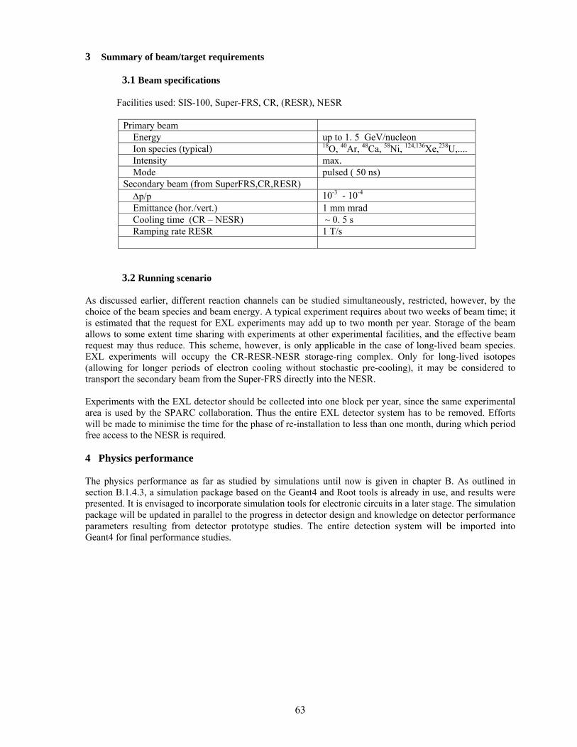
63
3 Summary of beam/target requirements
3.1 Beam specifications Facilities used: SIS-100, Super-FRS, CR, (RESR), NESR
Primary beam Energy up to 1. 5 GeV/nucleon Ion species (typical) 18O, 40Ar, 48Ca, 58Ni, 124,136Xe,238U,.... Intensity max. Mode pulsed ( 50 ns) Secondary beam (from SuperFRS,CR,RESR) ∆p/p 10-3 - 10-4 Emittance (hor./vert.) 1 mm mrad Cooling time (CR – NESR) ~ 0. 5 s Ramping rate RESR 1 T/s
3.2 Running scenario As discussed earlier, different reaction channels can be studied simultaneously, restricted, however, by the choice of the beam species and beam energy. A typical experiment requires about two weeks of beam time; it is estimated that the request for EXL experiments may add up to two month per year. Storage of the beam allows to some extent time sharing with experiments at other experimental facilities, and the effective beam request may thus reduce. This scheme, however, is only applicable in the case of long-lived beam species. EXL experiments will occupy the CR-RESR-NESR storage-ring complex. Only for long-lived isotopes (allowing for longer periods of electron cooling without stochastic pre-cooling), it may be considered to transport the secondary beam from the Super-FRS directly into the NESR. Experiments with the EXL detector should be collected into one block per year, since the same experimental area is used by the SPARC collaboration. Thus the entire EXL detector system has to be removed. Efforts will be made to minimise the time for the phase of re-installation to less than one month, during which period free access to the NESR is required. 4 Physics performance The physics performance as far as studied by simulations until now is given in chapter B. As outlined in section B.1.4.3, a simulation package based on the Geant4 and Root tools is already in use, and results were presented. It is envisaged to incorporate simulation tools for electronic circuits in a later stage. The simulation package will be updated in parallel to the progress in detector design and knowledge on detector performance parameters resulting from detector prototype studies. The entire detection system will be imported into Geant4 for final performance studies.
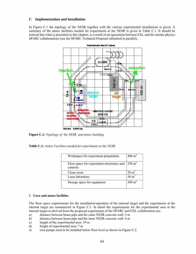
64
C Implementation and Installation
In Figure C.1 the topology of the NESR together with the various experimental installations is given. A summary of the annex facilities needed for experiments at the NESR is given in Table C.1. It should be noticed that what is presented in this chapter, is a result of an agreement between EXL and the atomic physics SPARC collaborations (see the SPARC Technical Proposal submitted in parallel).
Figure C.1: Topology of the NESR and annex building. Table C.1: Annex Facilities needed for experiments at the NESR.
1 Cave and annex facilities
The floor space requirements for the installation/operation of the internal target and the experiments at the internal target are summarized in Figure C.1. In detail the requirements for the experimental area at the internal target as derived from the proposed experiments of the SPARC and EXL collaboration are: a) distance between beam pipe and the outer NESR concrete wall: 5 m b) distance between beam pipe and the inner NESR concrete wall: 6 m c) length of the experimental area: 19 m d) height of experimental area: 7 m e) root pumps need to be installed below floor level as shown in Figure C.2.
Workspace for experiment preparation 400 m2
Floor space for experiment electronics and controls
250 m2
Clean room 20 m2 Laser laboratory 50 m2
Storage space for equipment 200 m2
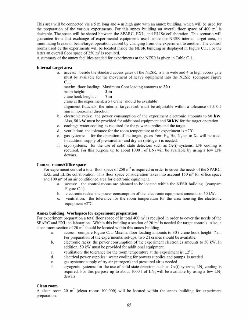
65
This area will be connected via a 5 m long and 4 m high gate with an annex building, which will be used for the preparation of the various experiments. For this annex building an overall floor space of 400 m2 is desirable. The space will be shared between the SPARC, EXL, and ELISe collaboration. This scenario will guarantee for a fast exchange of experimental equipments used inside the NESR internal target area, so minimizing breaks in beam/target operation caused by changing from one experiment to another. The control rooms used by the experiments will be located inside the NESR building as displayed in Figure C.1. For the latter an overall floor space of 250 m2 is required. A summary of the annex facilities needed for experiments at the NESR is given in Table C.1. Internal target area
a. access: beside the standard access gates of the NESR, a 5 m wide and 4 m high access gate must be available for the movement of heavy equipment into the NESR (compare Figure C.1). maxim. floor loading: Maximum floor loading amounts to 30 t beam height: 2 m crane hook height : 7 m crane at the experiment: a 5 t crane should be available alignment fiducials: the internal target itself must be adjustable within a tolerance of ± 0.5 mm in horizontal direction
b. electronic racks: the power consumption of the experiment electronic amounts to 50 kW. Also, 50 kW must be provided for additional equipment and 50 kW for the target operation.
c. cooling: water cooling is required for the power supplies and the target d. ventilation: the tolerance for the room temperature at the experiment is ±2oC e. gas systems: for the operation of the target, gases from H2, He, N2 up to Xe will be used.
In addition, supply of pressured air and dry air (nitrogen) is needed. f. cryo systems: for the use of solid state detectors such as Ge(i) systems, LN2 cooling is
required. For this purpose up to about 1000 l of LN2 will be available by using a few LN2 dewars.
Control rooms/Office space
For experiment control a total floor space of 250 m2 is required in order to cover the needs of the SPARC, EXL and ELISe collaboration. This floor space consideration takes into account 150 m2 for office space and 100 m2 of an air conditioned area for electronic equipment.
a. access: the control rooms are planned to be located within the NESR building (compare Figure C.1).
b. electronic racks: the power consumption of the electronic equipment amounts to 50 kW. c. ventilation: the tolerance for the room temperature for the area housing the electronic
equipment ±2oC
Annex building: Workspace for experiment preparation For experiment preparation a total floor space of in total 400 m2 is required in order to cover the needs of the SPARC and EXL collaboration. Within this building a section of 20 m2 is needed for target controls. Also, a clean room section of 20 m2 should be located within this annex building.
a. access: compare Figure C.1. Maxim. floor loading amounts to 30 t crane hook height: 7 m. For preparation of the experimental set-ups, two 2 t cranes should be available.
b. electronic racks: the power consumption of the experiment electronics amounts to 50 kW. In addition, 50 kW must be provided for additional equipment.
c. ventilation: the tolerance for the room temperature at the experiment is: ±2oC d. electrical power supplies: water cooling for powers supplies and pumps is needed e. gas systems: supply of try air (nitrogen) and pressured air is needed f. cryogenic systems: for the use of solid state detectors such as Ge(i) systems, LN2 cooling is
required. For this purpose up to about 1000 l of LN2 will be available by using a few LN2 dewars.
Clean room A clean room 20 m2 (clean room: 100,000) will be located within the annex building for experiment preparation.
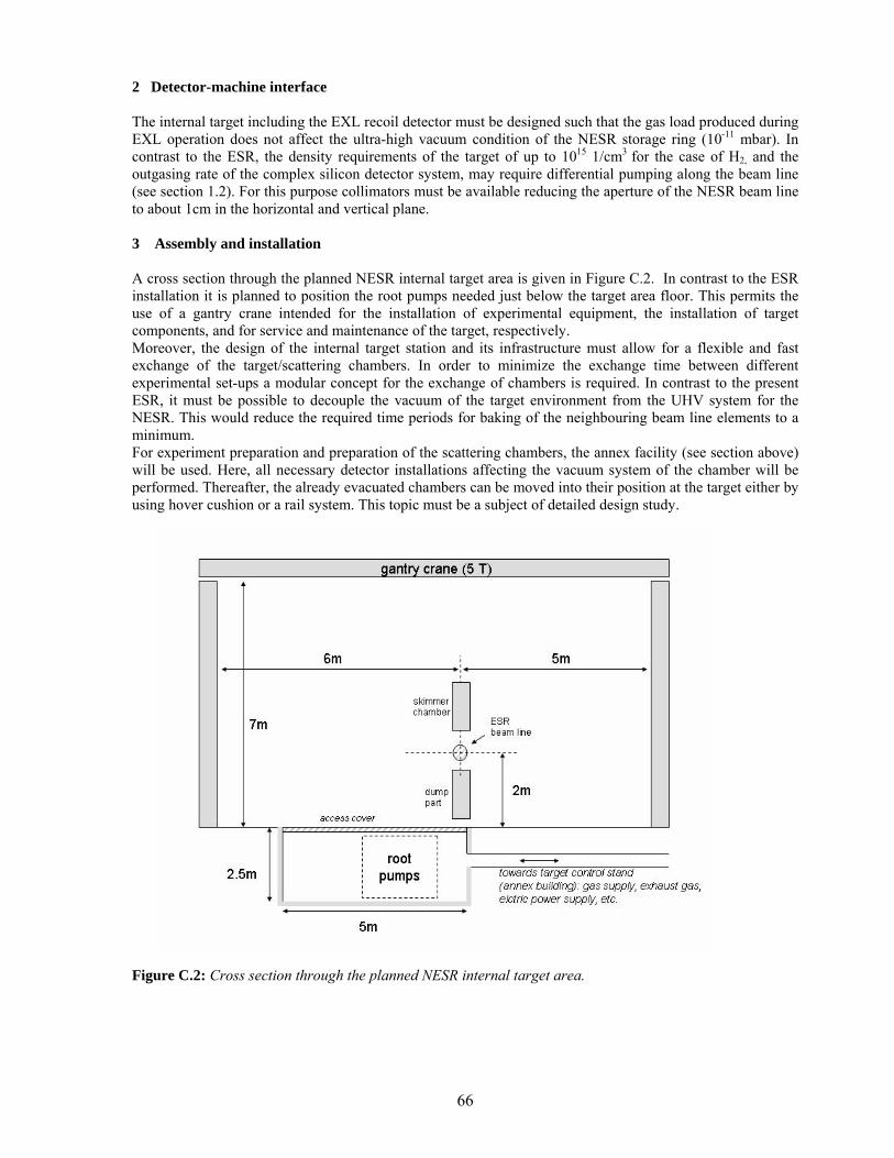
66
2 Detector-machine interface The internal target including the EXL recoil detector must be designed such that the gas load produced during EXL operation does not affect the ultra-high vacuum condition of the NESR storage ring (10-11 mbar). In contrast to the ESR, the density requirements of the target of up to 1015 1/cm3 for the case of H2, and the outgasing rate of the complex silicon detector system, may require differential pumping along the beam line (see section 1.2). For this purpose collimators must be available reducing the aperture of the NESR beam line to about 1cm in the horizontal and vertical plane.
3 Assembly and installation A cross section through the planned NESR internal target area is given in Figure C.2. In contrast to the ESR installation it is planned to position the root pumps needed just below the target area floor. This permits the use of a gantry crane intended for the installation of experimental equipment, the installation of target components, and for service and maintenance of the target, respectively. Moreover, the design of the internal target station and its infrastructure must allow for a flexible and fast exchange of the target/scattering chambers. In order to minimize the exchange time between different experimental set-ups a modular concept for the exchange of chambers is required. In contrast to the present ESR, it must be possible to decouple the vacuum of the target environment from the UHV system for the NESR. This would reduce the required time periods for baking of the neighbouring beam line elements to a minimum. For experiment preparation and preparation of the scattering chambers, the annex facility (see section above) will be used. Here, all necessary detector installations affecting the vacuum system of the chamber will be performed. Thereafter, the already evacuated chambers can be moved into their position at the target either by using hover cushion or a rail system. This topic must be a subject of detailed design study.
Figure C.2: Cross section through the planned NESR internal target area.
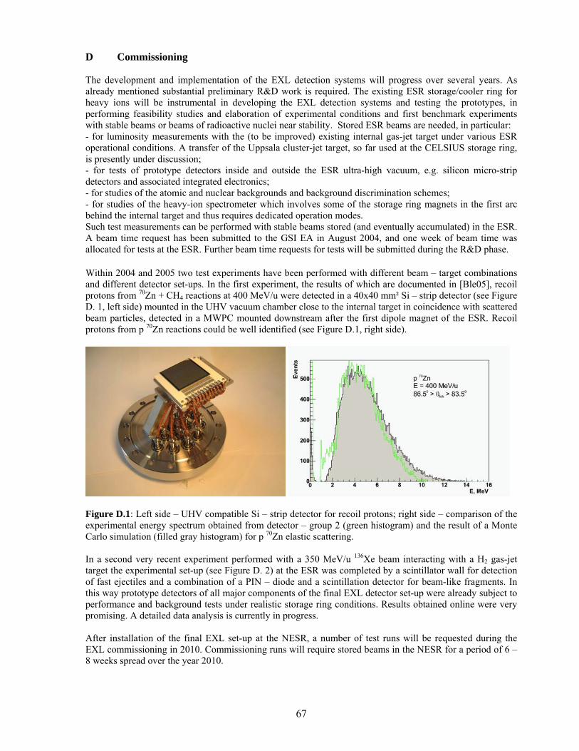
67
D Commissioning The development and implementation of the EXL detection systems will progress over several years. As already mentioned substantial preliminary R&D work is required. The existing ESR storage/cooler ring for heavy ions will be instrumental in developing the EXL detection systems and testing the prototypes, in performing feasibility studies and elaboration of experimental conditions and first benchmark experiments with stable beams or beams of radioactive nuclei near stability. Stored ESR beams are needed, in particular: - for luminosity measurements with the (to be improved) existing internal gas-jet target under various ESR operational conditions. A transfer of the Uppsala cluster-jet target, so far used at the CELSIUS storage ring, is presently under discussion; - for tests of prototype detectors inside and outside the ESR ultra-high vacuum, e.g. silicon micro-strip detectors and associated integrated electronics; - for studies of the atomic and nuclear backgrounds and background discrimination schemes; - for studies of the heavy-ion spectrometer which involves some of the storage ring magnets in the first arc behind the internal target and thus requires dedicated operation modes. Such test measurements can be performed with stable beams stored (and eventually accumulated) in the ESR. A beam time request has been submitted to the GSI EA in August 2004, and one week of beam time was allocated for tests at the ESR. Further beam time requests for tests will be submitted during the R&D phase. Within 2004 and 2005 two test experiments have been performed with different beam – target combinations and different detector set-ups. In the first experiment, the results of which are documented in [Ble05], recoil protons from 70Zn + CH4 reactions at 400 MeV/u were detected in a 40x40 mm² Si – strip detector (see Figure D. 1, left side) mounted in the UHV vacuum chamber close to the internal target in coincidence with scattered beam particles, detected in a MWPC mounted downstream after the first dipole magnet of the ESR. Recoil protons from p 70Zn reactions could be well identified (see Figure D.1, right side).
Figure D.1: Left side – UHV compatible Si – strip detector for recoil protons; right side – comparison of the experimental energy spectrum obtained from detector – group 2 (green histogram) and the result of a Monte Carlo simulation (filled gray histogram) for p 70Zn elastic scattering. In a second very recent experiment performed with a 350 MeV/u 136Xe beam interacting with a H2 gas-jet target the experimental set-up (see Figure D. 2) at the ESR was completed by a scintillator wall for detection of fast ejectiles and a combination of a PIN – diode and a scintillation detector for beam-like fragments. In this way prototype detectors of all major components of the final EXL detector set-up were already subject to performance and background tests under realistic storage ring conditions. Results obtained online were very promising. A detailed data analysis is currently in progress. After installation of the final EXL set-up at the NESR, a number of test runs will be requested during the EXL commissioning in 2010. Commissioning runs will require stored beams in the NESR for a period of 6 – 8 weeks spread over the year 2010.
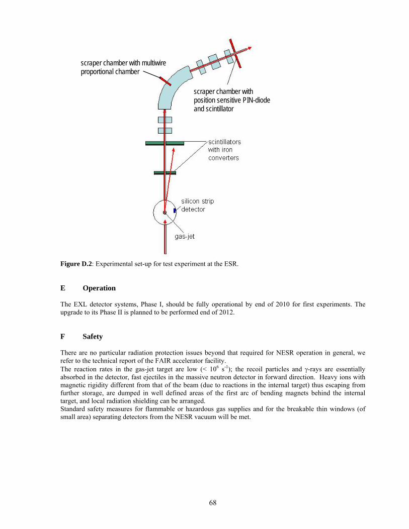
68
Figure D.2: Experimental set-up for test experiment at the ESR. E Operation The EXL detector systems, Phase I, should be fully operational by end of 2010 for first experiments. The upgrade to its Phase II is planned to be performed end of 2012. F Safety There are no particular radiation protection issues beyond that required for NESR operation in general, we refer to the technical report of the FAIR accelerator facility. The reaction rates in the gas-jet target are low (< 106 s-1); the recoil particles and γ-rays are essentially absorbed in the detector, fast ejectiles in the massive neutron detector in forward direction. Heavy ions with magnetic rigidity different from that of the beam (due to reactions in the internal target) thus escaping from further storage, are dumped in well defined areas of the first arc of bending magnets behind the internal target, and local radiation shielding can be arranged. Standard safety measures for flammable or hazardous gas supplies and for the breakable thin windows (of small area) separating detectors from the NESR vacuum will be met.
scraper chamber with position sensitive PIN-diode and scintillator
scraper chamber with multiwire proportional chamber
69
G Organisation and Responsibilities, Planning
1 Organisation of the collaboration, tasks and responsibilities
Several collaboration meetings have been organised: 22 June 2004 in Liverpool, 11 February 2005 at GSI, 28-30 September 2005 in Santiago de Compostela (joint with R3B). On these occasions, the structure of the collaboration has been discussed, organised and updated.
Collaboration Board:
The collaboration named a spokesperson and a deputy, as well as a GSI liaison and agreed on the representation on the Collaboration Board and its role. The Collaboration Board (CB) is formed out of the Management Board (collaboration spokesperson and deputy, GSI liaison, spokesperson of the EXL-EURONS JRA), see below, and the Technical Board (work group coordinators). The Chair of the Technical Board of R3B is also invited on the CB. The main duties of the CB are to monitor the progress of the project and the quality of the developments, to ensure the reporting procedure according to the demands of FAIR as well as publication of results, and to guarantee optimal communication between the participants and thus economical usage of the provided funding. The CB also organizes the collaboration meetings.
Members of the EXL Collaboration Board Spokesperson M. Chartier Deputy Spokesperson and GSI Liaison P. Egelhof EXL-EURONS JRA Spokesperson N. Kalantar Work Group Coordinators G. Colo, O. Kiselev, L. Westerberg, T. Stöhlker, P. Egelhof,
R. Lemmon, J.A. Scarpaci, B. Jakobsson, A. Krasznahorkay, K. Boretzky, D. Rohe, H. Weick, T. Fästermann, I. Lazarus, H. Simon
R3B Technical Board Chair/Deputy R. Lemmon / O. Tengblad Management Board:
The Management Board is formed out of the collaboration spokesperson and deputy, the GSI liaison and the spokesperson of the EXL-EURONS JRA. For the monitoring purpose, the Management Board requests internal reports from the work group coordinators at regular intervals which are discussed at the Collabroation Board meetings. The Management Board also deals with the issues of dissemination (conference abstract submissions, publications, etc.) and constitutes the writing committee of the reports requested by the FAIR management.
Members of the EXL Management Board Spokesperson M. Chartier Deputy Spokesperson and GSI Liaison P. Egelhof EXL-EURONS JRA Spokesperson N. Kalantar
Work Groups and Technical Board:
To guarantee that the various components of the project are properly dealt with, several work groups have been established (see Table G.1). These work groups are responsible for the different parts of the project. The responsibilities for the various tasks of the project have been agreed upon during the collaboration meetings and work group meetings. For each work group, two institutes serve as coordinators (see Table G.1). These institutes have named their responsible/contact person. The coordinators of the work groups constitute the Technical Board. The work groups meet and work on the various tasks assigned to them and report to the Collaboration Board via their coordinators (internal written reports are regularly requested by the Management Board). The work groups in charge of the detection systems have a clear overlap, both in terms of tasks and participants, with their R3B counterparts. In some cases the EXL detection systems work groups (γ-ray and charged particle calorimeter, slow-neutron detector and fast-ejectiles detector) have actually merged with the corresponding R3B work groups. In the case of the target-recoil detector and associated electronics, the EXL and R3B groups are working in close collaboration. Several common NUSTAR work groups have also been formed for simulations/analysis, data acquisition/slow control and γ-ray/charged-particle calorimeter.
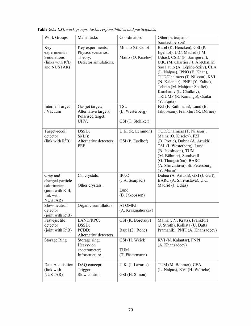
70
Table G.1: EXL work groups, tasks, responsibilities and participants.
Work Groups Main Tasks Coordinators
Other participants (contact person)
Key-experiments / Simulations (links with R3B and NUSTAR)
Key experiments; Physics scenarios; Theory; Detector simulations.
Milano (G. Colo) Mainz (O. Kiselev)
Basel (K. Hencken), GSI (P. Egelhof), U.C. Madrid (J.M. Udias), CSIC (P. Sarriguren), U.K. (M. Chartier / J. Al-Khalili), São Paulo (A. Lépine-Szily), CEA (L. Nalpas), IPNO (E. Khan), TUD/Chalmers (T. Nilsson), KVI (N. Kalantar), PNPI (Y. Zalite), Tehran (M. Mahjour-Shafiei), Kurchatov (L. Chulkov), TRIUMF (R. Kanungo), Osaka (Y. Fujita)
Internal Target / Vacuum
Gas-jet target; Alternative targets; Polarised target; UHV.
TSL (L. Westerberg) GSI (T. Stöhlker)
FZJ (F. Rathmann), Lund (B. Jakobsson), Frankfurt (R. Dörner)
Target-recoil detector (link with R3B)
DSSD; Si(Li); Alternative detectors; FEE.
U.K. (R. Lemmon) GSI (P. Egelhof)
TUD/Chalmers (T. Nilsson), Mainz (O. Kiselev), FZJ (D. Protic), Dubna (A. Artukh), TSL (L.Westerberg), Lund (B. Jakobsson), TUM (M. Böhmer), Sundsvall (G. Thungström), BARC (A. Shrivastava), St. Petersburg (Y. Murin)
γ-ray and charged-particle calorimeter (joint with R3B, link with NUSTAR)
CsI crystals. Other crystals.
IPNO (J.A. Scarpaci) Lund (B. Jakobsson)
Dubna (A. Artukh), GSI (J. Gerl), BARC (A. Shrivastava), U.C. Madrid (J. Udias)
Slow-neutron detector (joint with R3B)
Organic scintillators. ATOMKI (A. Krasznahorkay)
Fast-ejectile detector (joint with R3B)
LAND/RPC; DSSD; PCDD; Alternative detectors.
GSI (K. Boretzky) Basel (D. Rohe)
Mainz (J.V. Kratz), Frankfurt (J. Stroth), Kolkata (U. Datta Pramanik), PNPI (A. Khanzadeev)
Storage Ring Storage ring; Heavy-ion spectrometer; Infrastructure. .
GSI (H. Weick) TUM (T. Fästermann)
KVI (N. Kalantar), PNPI (A. Khanzadeev)
Data Acquisition (link with NUSTAR)
DAQ concept; Trigger; Slow control.
U.K. (I. Lazarus) GSI (H. Simon)
TUM (M. Böhmer), CEA (L. Nalpas), KVI (H. Wörtche)
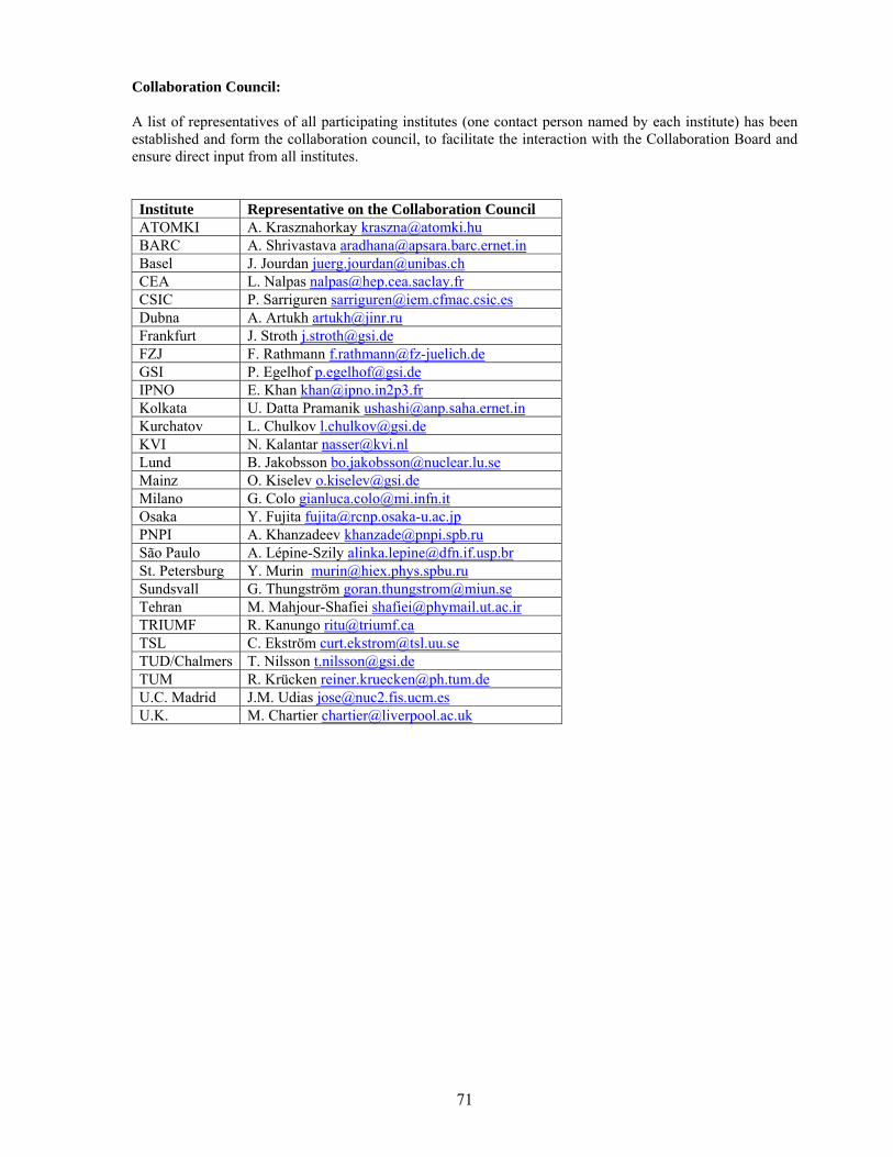
71
Collaboration Council: A list of representatives of all participating institutes (one contact person named by each institute) has been established and form the collaboration council, to facilitate the interaction with the Collaboration Board and ensure direct input from all institutes. Institute Representative on the Collaboration Council ATOMKI A. Krasznahorkay [email protected] BARC A. Shrivastava [email protected] Basel J. Jourdan [email protected] CEA L. Nalpas [email protected] CSIC P. Sarriguren [email protected] Dubna A. Artukh [email protected] Frankfurt J. Stroth [email protected] FZJ F. Rathmann [email protected] GSI P. Egelhof [email protected] IPNO E. Khan [email protected] Kolkata U. Datta Pramanik [email protected] Kurchatov L. Chulkov [email protected] KVI N. Kalantar [email protected] Lund B. Jakobsson [email protected] Mainz O. Kiselev [email protected] Milano G. Colo [email protected] Osaka Y. Fujita [email protected] PNPI A. Khanzadeev [email protected] São Paulo A. Lépine-Szily [email protected] St. Petersburg Y. Murin [email protected] Sundsvall G. Thungström [email protected] Tehran M. Mahjour-Shafiei [email protected] TRIUMF R. Kanungo [email protected] TSL C. Ekström [email protected] TUD/Chalmers T. Nilsson [email protected] TUM R. Krücken [email protected] U.C. Madrid J.M. Udias [email protected] U.K. M. Chartier [email protected]
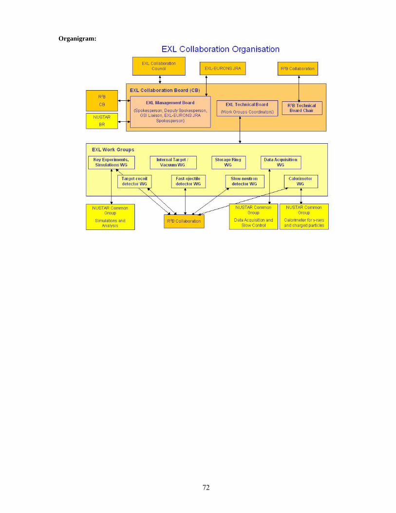
72
Organigram:

73
2 Contributions of the participating institutes All participating research teams have experience with regard to scientific or technological aspects addressed in this project and will participate according to their expertise and physics interests. Three of the participating institutes operate or have operated storage-cooler rings for hadrons or heavy ions (COSY at FZ-Jülich; CELSIUS at TSL, Uppsala; ESR at GSI, Darmstadt). External expert advice will be asked for when deemed necessary by the CB. Table G.2: EXL participating institutes, and contact persons (members of the Collaboration Council), and their contribution in the work groups. Institutes (contact person) Work Groups Contribution ATOMKI (A. Krasznahorkay [email protected])
Slow-neutron detector
Slow-neutron detector design and construction.
BARC (A. Shrivastava [email protected])
Target-recoil detector γ-ray and charged-particle calorimeter
DSSD and CsI testing.
Basel (J. Jourdan [email protected])
Key-experiments /Simulations Fast-ejectile detector
Astrophysics and nuclear reactions theory. Proton detection.
CEA (L. Nalpas [email protected])
Key-experiments /Simulations Target-recoil detector Data Acquisition
Target-recoil detector design and construction. R&D (DSSD, MAPS). Readout electronics design.
CSIC (P. Sarriguren [email protected])
Key-experiments /Simulations
Theory input for Gamow-Teller resonances and studies of nucleon-nucleus scattering in inverse kinematics.
Dubna (A. Artukh [email protected]) Target-recoil detector γ-ray and charged-particle calorimeter
Si and CsI detectors.
Frankfurt (J. Stroth [email protected]) Fast-ejectile detector Internal Target /Vaccuum
Fast neutron detectors design and construction. Alternative targets.
FZJ (F. Rathmann [email protected])
Internal Target /Vaccum Target-recoil detector
Polarized internal target. Thick Si/Ge detectors. R&D on Si(Li).
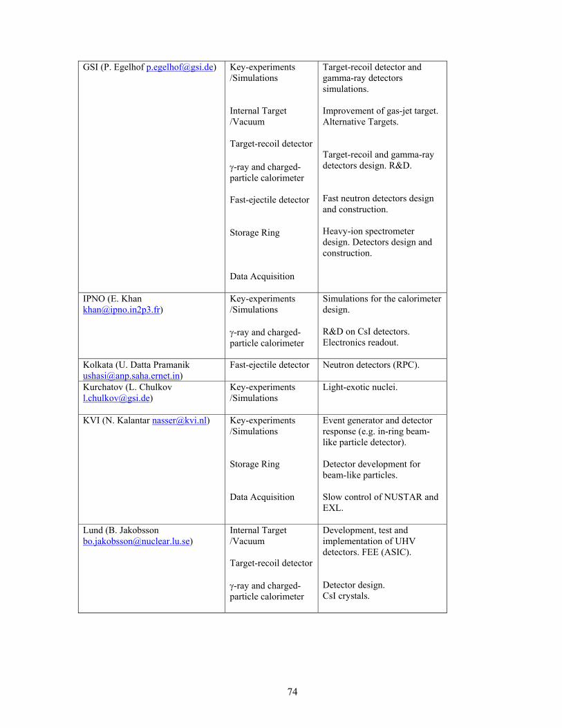
74
GSI (P. Egelhof [email protected]) Key-experiments
/Simulations Internal Target /Vacuum Target-recoil detector γ-ray and charged-particle calorimeter Fast-ejectile detector Storage Ring Data Acquisition
Target-recoil detector and gamma-ray detectors simulations. Improvement of gas-jet target. Alternative Targets. Target-recoil and gamma-ray detectors design. R&D. Fast neutron detectors design and construction. Heavy-ion spectrometer design. Detectors design and construction.
IPNO (E. Khan [email protected])
Key-experiments /Simulations γ-ray and charged-particle calorimeter
Simulations for the calorimeter design. R&D on CsI detectors. Electronics readout.
Kolkata (U. Datta Pramanik [email protected])
Fast-ejectile detector Neutron detectors (RPC).
Kurchatov (L. Chulkov [email protected])
Key-experiments /Simulations
Light-exotic nuclei.
KVI (N. Kalantar [email protected]) Key-experiments /Simulations Storage Ring Data Acquisition
Event generator and detector response (e.g. in-ring beam-like particle detector). Detector development for beam-like particles. Slow control of NUSTAR and EXL.
Lund (B. Jakobsson [email protected])
Internal Target /Vacuum Target-recoil detector γ-ray and charged-particle calorimeter
Development, test and implementation of UHV detectors. FEE (ASIC). Detector design. CsI crystals.
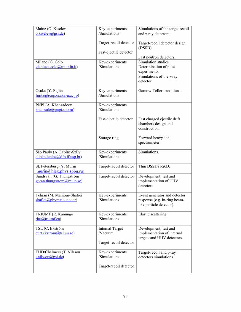
75
Mainz (O. Kiselev [email protected])
Key-experiments /Simulations Target-recoil detector Fast-ejectile detector
Simulations of the target recoil and γ-ray detectors. Target-recoil detector design (DSSD). Fast neutron detectors.
Milano (G. Colo [email protected])
Key-experiments /Simulations
Simulation studies. Determination of pilot experiments. Simulations of the γ-ray detector.
Osaka (Y. Fujita [email protected])
Key-experiments /Simulations
Gamow-Teller transitions.
PNPI (A. Khanzadeev [email protected])
Key-experiments /Simulations Fast-ejectile detector Storage ring
Fast charged ejectile drift chambers design and construction. Forward heavy-ion spectrometer.
São Paulo (A. Lépine-Szily [email protected])
Key-experiments /Simulations
Simulations.
St. Petersburg (Y. Murin [email protected])
Target-recoil detector Thin DSSDs R&D.
Sundsvall (G. Thungström [email protected])
Target-recoil detector Development, test and implementation of UHV detectors
Tehran (M. Mahjour-Shafiei [email protected])
Key-experiments /Simulations
Event generator and detector response (e.g. in-ring beam-like particle detector).
TRIUMF (R. Kanungo [email protected])
Key-experiments /Simulations
Elastic scattering.
TSL (C. Ekström [email protected])
Internal Target /Vacuum Target-recoil detector
Development, test and implementation of internal targets and UHV detectors.
TUD/Chalmers (T. Nilsson [email protected])
Key-experiments /Simulations Target-recoil detector
Target-recoil and γ-ray detectors simulations.

76
TUM (R. Krücken [email protected])
Storage Ring Target-recoil detector Data Acquisition
Forward heavy-ion spectrometer design and construction. Design and construction of position sensitive silicon detector stacks. Design and construction of various readout and DAQ modules.
U.C. Madrid (J.M. Udias [email protected])
Key-experiments /Simulations γ-ray and charged-particle calorimeter
Simulation studies for exotic nuclei (Gamow-Teller resonances). Event generator including FSI and other effects. γ-ray detectors I+D. Tests and simulations of new scintillators.
U.K. (M. Chartier [email protected])
Key-experiments /Simulations Target-recoil detector Data Acquisition
Reactions theory (QFS, knockout, transfer). Target-recoil detector simulations. Target-recoil detector design and construction. Front-end electronics (ASIC) design & assembly. R&D (DSSD, MAPS). DAQ system design.
77
H Relation to other Projects Evidently, there are common interests as far as the physics goals are concerned among the EXL, R3B, and ELISe proposals. The R3B proposal includes light-ion scattering complementing the storage ring experiments discussed here, covering the part of large momentum transfer. A target-recoil detector including the γ-ray detector, although of different specification, is also required and it is envisaged to develop a common electronics read-out scheme. The same is true for the next-generation RPC neutron detector. In the case of ELISe at the electron ring intersecting the NESR and for the proposed antiproton-ion collider, a forward spectrometer for the projectile fragments built into the NESR lattice is required, similar to the one discussed here. From both the common physics goals and similar development lines for subsets of the setups, a close collaboration among the participants of R3B, EXL and ELISe is most natural, and is manifested in the partial overlap in personnel and, in part, common work groups (see chapter G). Synergy with LoIs outside NUSTAR is evident as well. The internal target will be used by atomic physics groups (SPARC proposal), these groups are in part also planning for a (UHV) detector system similar to the recoil detector and will also use a fragment forward spectrometer; a close collaboration is envisaged and discussions have already started. The installation scheme (see chapter C) was worked out jointly. Silicon tracker devices (here, the target recoil detector) are substantial devices in both the PANDA and the CBM proposals; first discussions have taken place to establish some possible joint effort.
78
I Annex: The NUSTAR Data Acquisition Concept The NUSTAR data acquisition (DAQ) concept tries to incorporate and deal with the changes that are related to the discontinuation of production and support of all CAMAC and FASTBUS modules, together with the much increasing number of channels in the different experiments. Dedicated front-end electronics boards are foreseen in most experiments for NUSTAR. The other main issue is to provide a maximum interoperability of the different setups of the NUSTAR facility as many parts of particular setups, detectors systems and their associated DAQ systems. As an example may serve the in-ring instrumentation of the NESR that will be used in parallel by the EXL and ELISe collaborations. The same holds for the combination Super-FRS instrumentation – R3B setup, or gamma spectroscopy arrays in conjunction with reaction setups. As the communities overlap to a large extend it is favourable to come up with a combined DAQ framework that allows sharing expertise, thus saving manpower and running cost. The GSI MBS [i] system is an example for such a flexible DAQ scheme, that provides a generalized multi-processor environment, suitable for the readout, control and data storage of heterogeneous setups. The necessary extensions of the scheme have to be evaluated and integrated into the developing system by the NUSTAR DAQ group. A major part of this will be the integration of ‘foreign’ stand-alone DAQ systems or similarly the control and operation of various front-end electronics. System integration should be possible at different stages of the DAQ system.
(a) “NUSTAR” DAQ systems: It should be possible to couple different standalone “NUSTAR” DAQ systems, together in a simple way. Typically the individual DAQ systems are used to setup and debug detector groups or experiments. By foreseeing the necessary interconnects for triggers and control signals and by keeping the modularity of the system in mind while building local triggers and event buffer capabilities, such a scheme can be realized. The R3B/CaveC setup together with the current FRS is an example where the necessary prerequisites are currently specified. Note, that different schemes of coupling might be used here: (i) the systems are synchronized with one common trigger (ii) the DAQ systems run standalone and are synchronized via timestamps (see section I.1).
(b) Front-end electronics (FEE): For the common NUSTAR DAQ system, specific front-end electronics together with its digitization part is seen as part of the detector. This has the advantage that all analogue signal processing is done by the working groups with the most experience on the particular detector system. Only the control, trigger and data flow will be specified as interface description by the common NUSTAR DAQ system. This includes the necessary trigger types to be implemented, like data, calibration and synchronization triggers together with a prescription how to lock the FEE to realize a clearly defined dead time of the total system. The timestamp-data interface has to be specified and slow control issues like version numbering, firmware revisions, software up/download from e.g. databases to particular FEE boards require R&D work. A first implementation for the digital interface that allows slow control and experiment data transfer from and to FEE boards already exists and is in use; the GTB-BUS a GSI development.
(c) Inhomogeneous DAQ systems: From our operating experience we know, that especially the large gamma arrays come with their own customized DAQ systems. As has been seen e.g. for the RISINGii experiments at the FRS, a certain flexibility of the host (here the NUSTAR) DAQ system is mandatory to couple these systems together. The development and implementation of the TITRIS timestamp module together with the time-ordered writing to mass storage within the MBS framework is an example for such integration efforts.
Implementation: As a first step we want to implement within the years a standardized front-end electronics (e.g. for the R³B/CAVEC) for fast signals. It will consist of a taquila [iii] front-end board that has been developed for the upgrade of the FOPI experiment at GSI. These boards can be used to record 16 channels of time-signals, amplitude- or charge-signals at a moderate channel cost. As interface to the detector additional FEE (e.g. [iv]) boards are used, that are used to amplify, shape and split the signals prior to their input the digitizer board. Such a system can be thought of being already a replacement for a full e.g. NIM based pre-amplifier, discriminator and CAMAC/FASTBUS based digitizer chain. The taquila boards provide also a simple time stamp mechanism. We will study the behaviour of such a system within the next two years at the R³B/CAVEC setup using the LAND neutron-detector readout as reference implementation. Further R&D steps will be accomplished to come to a fully operable FEE environment. The FEE is digitally attached via the GTB bus to a VME based processor board [v] that can be used to control the FEE readout process and to perform online data reduction (see Figure I.1).
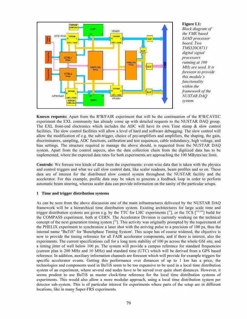
79
Figure I.1: Block diagram of the VME based SAM3 processor board. Two TMS320C6711 digital signal processors running at 100 MHz are used. It is foreseen to provide this module’s functionality within the framework of the NUSTAR DAQ system.
Known requests: Apart from the R³B/FAIR experiment that will be the continuation of the R³B/CAVEC experiment the EXL community has already come up with detailed requests to the NUSTAR DAQ group. The EXL front-end electronics which includes the ADC will have its own Time stamp & slow control facilities. The slow control facilities will allow a level of hard and software debugging. The slow control will allow the modification of e.g. the sub-trigger, choice of pre-amplifiers and amplifiers, the shaping, the gain, discriminators, sampling, ADC functions, calibration and test sequences, cable redundancy, high voltage, and bias settings. The structure required to manage the above should, is requested from the NUSTAR DAQ system. Apart from the control aspects, also the data collection chain from the digitized data has to be implemented, where the expected data rates for both experiments are approaching the 100 MBytes/sec limit. Controls: We foresee two kinds of data from the experiments: event-wise data that is taken with the physics and control triggers and what we call slow control data, like scaler readouts, beam profiles and so on. These data are of interest for the distributed slow control system throughout the NUSTAR facility and the accelerator. For this example, profile data may be taken to generate a feedback loop in order to perform automatic beam steering, whereas scaler data can provide information on the sanity of the particular setups. 1 Time and trigger distribution systems As can be seen from the above discussion one of the main infrastructures delivered by the NUSTAR DAQ framework will be a hierarchical time distribution system. Existing architectures for large scale time and trigger distribution systems are given e.g. by the TTC for LHC experiments [vi], or the TCS [vii,viii] build for the COMPASS experiment, both at CERN. The Accelerator Division is currently working on the technical concept of the next generation timing system [ix]. This activity was originally prompted by the requirement of the PHELIX experiment to synchronize a laser shot with the arriving pulse to a precision of 100 ps, thus the internal name "BuTiS" for 'Bunchphase Timing System'. This scope has of course widened, the objective is now to provide the timing reference for all FAIR accelerator components, and if there is interest, also the experiments. The current specifications call for a long term stability of 100 ps across the whole GSI site, and a timing jitter of well below 100 ps. The system will provide a campus reference for standard frequencies (current plan is 200 MHz and 10 MHz) and standard time (UTC) which will be derived from a GPS based reference. In addition, auxiliary information channels are foreseen which will provide for example triggers for specific accelerator events. Getting this performance over distances of up to 1 km has a price, the technologies and components used in BuTiS seem to be too expensive to be used in a local time distribution system of an experiment, where several end nodes have to be served over quite short distances. However, it seems prudent to use BuTiS as master clock/time reference for the local time distribution systems of experiments. This would also allow a more modular approach, using a local time distribution system per detector sub-system. This is of particular interest for experiments where parts of the setup are in different locations, like in many Super-FRS experiments.
80
Local time-stamps: A campus wide synchronisation method allows for common timestamps between different experiments. The common clock is not enough on its own for full synchronisation - one needs to be able to correlate particular clock edges with particular values of the timestamp counters in order to start from the same timestamp value everywhere. Existing local time distribution systems like e.g. the GSI TITRIS [x] modular, which is similar to the CENTRUM built by GANIL [xi] and also the proposed AGATA GTS [xii], have to be adapted to allow for the synchronization to the BUTiS clock with a defined phase. Different types of FEE will also provide their local clocks. One may consider the following scenarios:
a) Self-made timestamps, where a specification of the latency of the front-end trigger with respect to the timestamps is needed in order to be able to synchronize the particular data to the overall system. The latency can be automatically determined e.g. by using generated synchronization events from the host DAQ system to the particular timestamp generating system. Another question is how to couple local systems to BuTiS. One BuTiS receiver per local timestamping system might be too expensive it is a subject to further R&D whether an additional (experiment-wide) time distribution layer is desirable.
b) For the standardized NUSTAR DAQ one should consider to build a novel “Titris II” module in different form factors, to be used in VME crates or attached to the FEE, which can be coupled to the BuTiS system.
We can base our studies e.g. on the already existing use the techniques of timestamping followed by software filters and triggers which were developed for GREAT. Within GREAT these items are handled by the Metronome and its interface to the ADC cards. Within the next years we need to specify latencies for trigger decisions depending on the physics of the trigger, taking into account the limited pre-processing buffer depths, and their associated acceptance window. Here dedicated input from the different experiments is needed to come up with a generalized and flexible scheme. 2 Data collection and storage Data collection and mass storage is another issue. If one deal with 10-100 Mbytes/sec data form the experiments at maximum as estimated for the EXL and R³B setups, the total data produced per day is in the order of 1-10 TBytes. This means, for the NUSTAR experiments we expect not more than 500TB/year data. The requested band-width for data transfer is in accordance with the expected rates that can be transferred using standard network components. The demand to run independent NUSTAR DAQ modules that can be combined in a flexible manner poses certain requirements to the transport layer in between the experiments and to the mass storage.
1. Standardized sub-event format; this is favourable in order to facilitate to event building from different data sources.
2. Flexible event builder combinations; one may consider to use different parts of the data stream at different locations to perform different tasks: mass storage; online analysis; slow control feedback.
3. Standardized event format; to be used to use a common unpacking scheme for data analysis. The NUSTAR DAQ system will provide the necessary data collection procedures for standard electronics module (e.g. VME) and collection form FE-boards that follow the conventions for the standardized digital interfaces (e.g. GTB). The necessary R&D work will be done in parallel to the various electronic developments in the NUSTAR community in close collaboration with the respective groups, co-ordinated by the DAQ responsible for the particular experiments. 3 Slow control and monitoring The slow control requests for the NUSTAR DAQ system go two ways. First the sub-systems should provide certain information in order to be in the monitoring process of the total experiment specific combination of different DAQ systems at different locations. This functionality exceeds the implemented acquisition controls: a command dispatcher and log message facility the sense, that also e.g. different online scalers providing dead-time and rates should be available. This implies also that there should be an extended way to be able to probe the actual configuration of the setup (this means an extended object with distances between the different parts of several 100 meters) including software revisions on the FE-boards and other related
81
information. Probing means in this context, that the individual sub-systems provide information about the parameters and interlock conditions to be monitored. One may also think of status requests that return FPGA codes, hard- and software-revisions and related information. The other way is the information that will be provided by the experiments DAQ and analysis stage to:
1. the accelerator; to allow e.g. automatic beam steering [xiii] like it is done at CERN PSB to continuously adjust experiments settings without manual interference.
2. the general slow controls of the experiment or setup, allowing to define interlock and warning conditions.
3. any other item not mentioned here that requires information of the experiments status extracted from the online data.
The advantage of such a scheme is that controls get their information from the different local systems so that the expertise is kept locally also. The implementation of the above scheme will be an adaptive process, where tests of the method are and can be already done at existing setups, which will lead to a final design, also with the input of the locally existing controls group. The final specification will be provided in the Technical Design report.
82
J References [Abb03] M. Abbrescia et al., Nucl. Instr. Meth. A 508 (2003) 79. [Adv03] V. Avdeichikov et al., Nucl. Instr. Meth. A501 (2003) 505. [Aki04] A.V. Akindinov et al., Nucl. Instr. Meth. A 533 (2004) 93. [Ago03] S. Agostinelli et al., Nucl. Instr. and Meth., A506(2003) 250. [Alk02] G.D. Alkhazov et al., Nucl. Phys. A 712 (2002) 269. [Alt01] S. Altieri et al., Nucl. Instr. Meth. A 461 (2001) 57. [Amo04] F. Amorini et al., Proceedings of 9 Topical Seminar on Innovative Particle and Radiation Detectors, Siena, Italy 2004, published in Nucl. Phys. B Proc. Suppl. [Amo05] F. Amorini et al., submitted to Nucl. Instr. Meth. A . [Aug04] J.-E. Augustin, Nucl. Instr. Meth. A 535 (2004) 36. [Ber87] M. Berz et al., Nucl. Instr. Meth. A 258 (1987) 402. [Bla92] Th. Blaich et al., Nucl. Instr. Meth. A 314 (1992) 136. [Bla02] A. Blanco et al., Nucl. Instr. Meth. A 485 (2002) 328. [Ble05] A. Bleile et al., GSI Scientific Report 2004, ISSN 0174-0814 (2005) 92. [Bor03] K. Boretzky et al., PRC 68 (2003) 024317. [Bor96] J. von Borany et al., Nucl. Instr. Meth. A 377 (1996) 514. [Bru97] R. Brun et al., Nucl. Instr. Meth. A 389 (1997) 81. [Car96] G. Cardella et al., Nucl. Instr. Meth. A 378 (1996) 262. [CDR01] An International accelerator Facility for Beams of Ions and Antiprotons, Conceptual Design Report, 11/2001. [Cer96] E. Cerron Zeballos et al., Nucl. Instr. Meth. A 374 (1996) 132. [Cho01] K.-B. Cho et al., Extended programme of the 2001 IEEE CCD & Advanced Image Sensors Workshop, Lake Tahoe, USA. [Col03] P.R. Collins, Nucl. Phys. B (Proc. Suppl.) 117 (2003) 391. [Eks97] C. Ekström, Nucl. Phys. A 626 (1997) 405c. [Ege97] P. Egelhof, World Scientific, ISBN 981-02-3140 (1997) 178. [Fix91] J Fixdal, Mechanical design and structural calculations of the new experimental vacuum chamber for the CELSIUS storage ring, Technical note CERN MT-MF/91-03 Jon Fixdal, Master thesis, Mechanical design and development of thin-walled vacuum chamber. [FLUKA] http://www.fluka.org and reference therein. [Fon00] P. Fonte et al., Nucl. Instr. Meth. A 449 (2000) 295. [Fon00b] P. Fonte et al., Nucl. Instr. Meth. A 456 (2000) 6. [Goe04] M. J. van Goethen et al., Nucl. Instr. Meth. A 526 (2004) 455. [Gr03] R. E. Grisenti et al., Phys. Rev. Lett. 90 (2003) 234501. [Har01] M.N. Harakeh et al., Oxford Studies in Nucl. Res., Vol.24 (2001). [Häu88] O.Häusser et al., Phys. Rev. C 37 (1988) 1119. [Hof01] F. Hoffmann et al., Phys. Rev. C 64 (2001) 034314. [Iwa97] N. Iwasa et al., Nucl. Instr. Meth. B 126 (1997) 284. [Kit85] P. Kitching et al., Nucl. Phys. 15 (1985) 43. [Kle01] S. Kleinfelder et al., presented at the 2001 International Solid State Circuits Conference. [Kle03] O. Klepper et al., Nucl. Instr. Meth. B 204 (2003) 553. [Kra01] A. Krämer et al., Nucl. Instr. Meth. B 174 (2001) 205. [Laz01] I.H. Lazarus et al., IEEE Tans. Nucl. Sci. 48 (2001) 567. [Lla66] Llacer, IEEE Trans. Nucl. Sci., NS 13, No. 1 (1966) 93. [Lop04] L. Lopes et al., Nucl. Instr. Meth. A 533 (2004) 121. [Lov81] W.G. Love and M.A. Franey, Phys. Rev. C 24 (1981) 1073. [Man04] A. Mangiarotti et al., Nucl. Instr. Meth. A 533 (2004) 16. [Mus98] A.Musumarra et al., Nucl. Instr. Meth. A 409 (1998) 414. [Mut00] M. Mutterer et al., IEEE Transactions on Nuclear Science 47 (2000) 756. [Mut04] M. Mutterer, private communication. [Nol00] F. Nolden et al., Nucl. Instr. Meth. A 441 (2000) 219. [Rei97] H. Reich et. al., Nucl. Phys. A 626 (1997) 417c. [Rie03] W. Riegler et al., Nucl. Instr. Meth. A 500 (2003) 144. [RPC04] Proceedings of the seventh international workshop on resistive plate chambers and related detectors, Clermont-Ferrand, France, 20-22.Oct 2003, Nucl. Instr. Meth. A 533 (2004) 1-238
83
[Sch98] C. Scheidenberger et al., Nucl. Instr. Meth. B 142 (1998) 441. [Sim99] H. Simon et al., Phys.Rev. Lett 83 (1999) 496. [Sto95] T. Stoehlker et al., Phys. Rev. A 51 (1995) 2098. [Sto98] T. Stoehlker et al., Phys. Rev. A 58 (1998) 2043. [Thu97] G. Thungström et al., Nucl. Instr. Meth. A 391 (1997) 315. [Tud99] S.Tudisco et al., Nucl. Instr. Meth. A 426 (1999) 436. [Tum04] A. Tumino et al., Phys. Rev. 67 (2003) 065803. [Yan01] G. Yang et al., Extended programme of the 2001 IEEE CCD & Advanced Image Sensors Workshop, Lake Tahoe, USA. [YanI] D.X.D. Yang et al., IEEE Journal of Solid-State Circuits, vol. 34, n. 12, 1821. [YanII] D.X.D. Yang et al., IEEE Journal of Solid-State Circuits, vol. 34, n. 3, 348. i The New data Acquisition System at GSI, H.G. Essel, J. Hoffmann, N. Kurz, R.S. Mayer, W. Ott, D. Schall, IEEE Trans. Nucl. Sci. 43 (1996), 132; The General Purpose Data Acquisition System MBS, H.G. Essel, N.Kurz, IEEE Trans. Nucl. Sci. 47 (2000), 337. ii J. Hoffmann and N. Kurz, RISING Data Acquisition with MBS:Event Synchronization with Time Stamp Modules, GSI Scientific Report, p. 224.,2002. iii A New TAC Based Multi Channel Front-End Electronics for TOF Experiments with Very High Time Resolution, K.Koch, H.Hardel, R.Schulze, E.Badura, J.Hoffmann (GSI), IEEE Conf Proc. Nucl. Sci. Symp., Med. Im. Conf., Symp. Nucl. Power Sys. and 14th Int. Workshop on Room Temp. Semic. X- and Gamma- Ray Det., Oct. 16-22, 2004, Rome, Italy, to be published. iv FOPI-Collaboration, "Upgrading the FOPI detector system", GSI Scientific Report, p. 177, 1998; A.Schüttauf et. al., "Timing Resistive Plate Counters (RPC) in FOPI", GSI Scientific Report, p. 231, 2003. v Development of New Readout Processor SAM3, J.Hoffmann, W.Ott, GSI Scientific Report, p. 193, 2002. vi http://ttc.web.cern.ch/TTC/intro.html. vii I. Konorov at al., The trigger control system for the COMPASS Experiment. IEEE Nuclear Science Symposium Conference Record (2002). viii L. Schmitt et al., The DAQ of the COMPASS Experiment. IEEE Trans. Nucl. Sci. (2004). ix P.Moritz ([email protected]), private communication. x http://www-linux.gsi.de/~mbs/v43/manual/gm_mbs_r.pdf. xi http://nnsa.dl.ac.uk/documents/edoc421/edoc421.pdf. xii http://agata.pd.infn.it/documents/week9152003/MarcoBellato.pdf. xiii ’Intelligent’ automatic beam steering and shaping, A. Jansson and M. Lindroos, CERN, Geneva, Switzerland, Proceedings of EPAC 2000 conference.