Embed Size (px)
Citation preview

OKFF
TECEprofil
Sanitary systems
TECHNICAL GUIDELINES
3-2
TECEprofi
l
TECEprofil dry-wall construction system 3-4
System description 3-5
Fields of application 3-6
System installation/instructions 3-7
Standard heights of installation walls 3-7
Standard applications 3-7
Building a supporting frame with module installation 3-12
Covering the facing with plasterboard 3-13
Filling of plasterboard panels 3-15
Facing for highly wet areas 3-16
Possible pre-wall heights and depths 3-18
Limits 3-19
Protection against moisture 3-19
Floor fixing 3-19
Equipotential bonding 3-19
Console loads 3-20
TECEprofil universal module 3-21
Installation in a TECEprofil pre-wall 3-21
Installation in front of a solid wall 3-22
Installation in a floor-to-ceiling C-profile metal stud wall 3-25
Installation in floor-to-ceiling metal stud wall with UA-profiles 3-26
Installation in a wooden stud wall 3-27
Attaching individual modules to the floor 3-27
Toilet module with connection for odour extraction 3-28
Individual or modular construction 3-30
Installing the vertical strut in the toilet module 3-30
Contents
3-3
TECEprofi
l
TECEprofil bath construction 3-31
Shower toilet solutions 3-34
Toilet module for shower toilets with power connection 3-34
Fine installation kit for shower toilet module 3-34
Setting up the TECEone shower toilet on the toilet module 3-37
TOTO Neorest shower toilet module 3-38
Shower toilet attachments 3-38
TECEprofil toilet module for baby/children's standing toilet 3-39
Barrier-free construction with TECEprofil 3-40
Planning guidelines 3-40
Barrier-free toilet system in a TECEprofil wall 3-41
Barrier-free toilet system in an individual modular construction 3-42
TECEprofil Geronto module 3-42
Sound insulation 3-45
Relevant standards 3-45
TECEprofil sound insulation verification 3-47
TECEprofil dry-wall construction system – sound insulation according to DIN 4109-1:2016-07 3-52
TECEbox brick-wall structure system – sound insulation according to DIN 4109-1:2016-07 3-56
Fire protection 3-58
TECEprofil dividing walls with fire protection requirements 3-58
Construction of a dividing wall (EI 30–EI 120) 3-58

3-4
TECEprofi
l
TECEprofil – dry-wall construction system
TECEprofil dry-wall construction systemTECEprofil is a pre-wall system that has proven its value over many years, and can be used to create bathroom walls quickly and effectively. The fitter not only produces the sanitary and heating installations but with TECEprofil, he is also able to provide complete bathrooms with sur-faces ready for tiling, all from a single source.
TECEprofil is a dry-wall construction system which is particularly suitable for the renovation of old buildings due to its flexibility. Thanks to the time and cost savings com-pared with bricked-in pre-walls, the TECEprofil system is also of interest for new builds. The design freedom offered by the TECEprofil allows the fitter to realise unconventional bathrooms, and offers generous scope for creative ideas.
Bathroom walls with TECEprofil – before
Bathroom walls with TECEprofil – after
3-5
TECEprofi
l
The TECEprofil system offers universal modules for popu-lar applications. These modules not only simplify installa-tion in a TECEprofil wall, but can also be used for conven-tional dry-wall constructions and as individual modules.
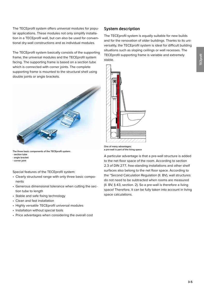
The TECEprofil system basically consists of the supporting frame, the universal modules and the TECEprofil system facing. The supporting frame is based on a section tube which is connected with corner joints. The complete supporting frame is mounted to the structural shell using double joints or angle brackets.
The three basic components of the TECEprofil system: - section tube - angle bracket - corner joint
Special features of the TECEprofil system:• Clearly structured range with only three basic compo-
nents• Generous dimensional tolerance when cutting the sec-
tion tube to length• Stable and safe fixing technology• Clean and fast installation• Highly versatile TECEprofil universal modules• Installation without special tools• Price advantages when considering the overall cost
System description
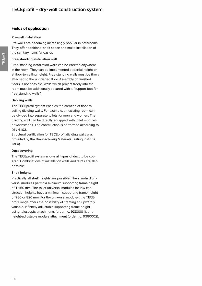
The TECEprofil system is equally suitable for new builds and for the renovation of older buildings. Thanks to its uni-versality, the TECEprofil system is ideal for difficult building situations such as sloping ceilings or wall recesses. The TECEprofil supporting frame is variable and extremely stable.
One of many advantages: a pre-wall is part of the living space
A particular advantage is that a pre-wall structure is added to the net floor space of the room. According to section 2.3 of DIN 277, free-standing installations and other shelf surfaces also belong to the net floor space. According to the “Second Calculation Regulation (II. BV), wall structures do not need to be subtracted when rooms are measured (II. BV, § 43, section. 2). So a pre-wall is therefore a living space! Therefore, it can be fully taken into account in living space calculations.
3-6
TECEprofi
l
Fields of application
Pre-wall installation
Pre-walls are becoming increasingly popular in bathrooms. They offer additional shelf space and make installation of the sanitary items far easier.
Free-standing installation wall
Free-standing installation walls can be erected anywhere in the room. They can be implemented at partial height or at floor-to-ceiling height. Free-standing walls must be firmly attached to the unfinished floor. Assembly on finished floors is not possible. Walls which project freely into the room must be additionally secured with a “support foot for free-standing walls”.
Dividing walls
The TECEprofil system enables the creation of floor-to-ceiling dividing walls. For example, an existing room can be divided into separate toilets for men and women. The dividing wall can be directly equipped with toilet modules or washstands. The construction is performed according to DIN 4103.Structural certification for TECEprofil dividing walls was provided by the Braunschweig Materials Testing Institute (MPA).
Duct covering
The TECEprofil system allows all types of duct to be cov-ered. Combinations of installation walls and ducts are also possible.
Shelf heights
Practically all shelf heights are possible. The standard uni-versal modules permit a minimum supporting frame height of 1,150 mm. The toilet universal modules for low con-struction heights have a minimum supporting frame height of 980 or 820 mm. For the universal modules, the TECE-profil range offers the possibility of creating an upwardly variable, infinitely adjustable supporting frame height using telescopic attachments (order no. 9380001), or a height-adjustable module attachment (order no. 9380002).
TECEprofil – dry-wall construction system
3-7
TECEprofi
l
System installation/instructionsWhen installing a TECEprofil bathroom wall, minimum distances for struts and fixings must be adhered to. In the following sections, the guidelines for installing the system will be explained.
Standard heights of installation walls
The standard supporting frame height of a TECEprofil pre-wall is 1,150 mm. This produces a toilet seat height of 430 mm.
Tip:For reasons of comfort, we recommend a seat height of 450 mm. The height of the supporting frame in this case is 1,170 mm. To guarantee secure fixing of the facing, a hori-zontal TECEprofil strut must be integrated at least every 650 mm.
Toilet seat height: Standard (left ) and comfort
The dimensions of the TECE facing are 625 x 1,350 x 18 mm. The maximum floor construction is 200 mm.
Facing dimensions
For easier installation, all universal modules have a meter line stamped on them.
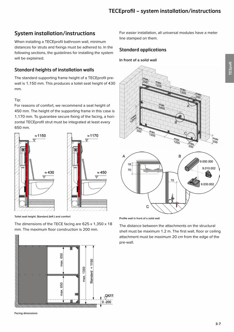
Standard applications
In front of a solid wall
Profile wall in front of a solid wall
The distance between the attachments on the structural shell must be maximum 1.2 m. The first wall, floor or ceiling attachment must be maximum 20 cm from the edge of the pre-wall.
TECEprofil – system installation/instructions
3-8
TECEprofi
l
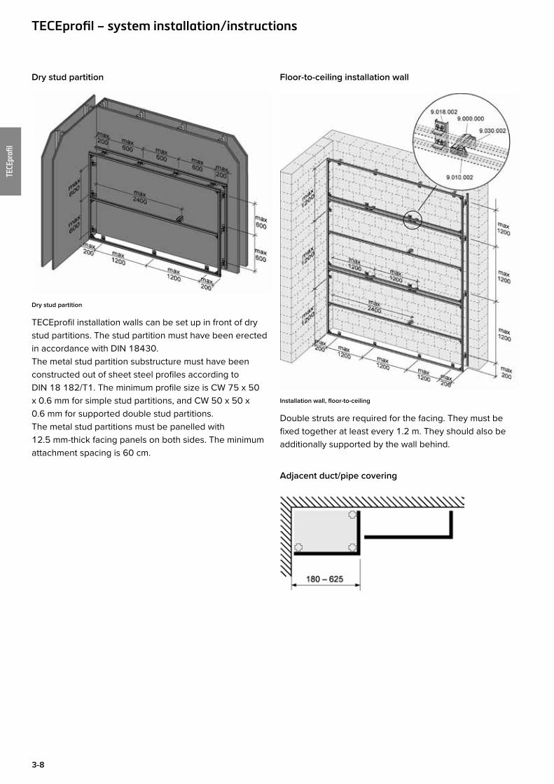
Dry stud partition
Dry stud partition
TECEprofil installation walls can be set up in front of dry stud partitions. The stud partition must have been erected in accordance with DIN 18430. The metal stud partition substructure must have been constructed out of sheet steel profiles according to DIN 18 182/T1. The minimum profile size is CW 75 x 50 x 0.6 mm for simple stud partitions, and CW 50 x 50 x 0.6 mm for supported double stud partitions. The metal stud partitions must be panelled with 12.5 mm-thick facing panels on both sides. The minimum attachment spacing is 60 cm.
Floor-to-ceiling installation wall
Installation wall, floor-to-ceiling
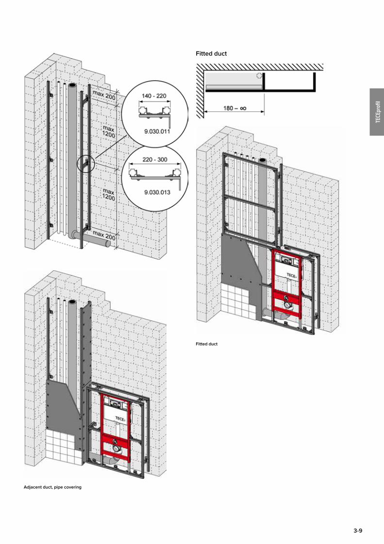
Double struts are required for the facing. They must be fixed together at least every 1.2 m. They should also be additionally supported by the wall behind.
Adjacent duct/pipe covering
TECEprofil – system installation/instructions
3-9
TECEprofi
l
Adjacent duct, pipe covering
Fitted duct
Fitted duct
3-10
TECEprofi
l
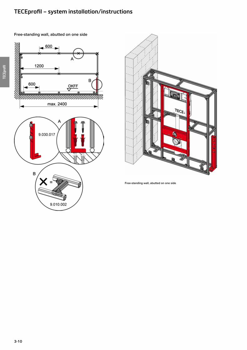
Free-standing wall, abutted on one side
Free-standing wall, abutted on one side
TECEprofil – system installation/instructions
3-11
TECEprofi
l
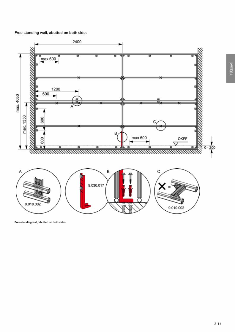
Free-standing wall, abutted on both sides
Free-standing wall, abutted on both sides
3-12
TECEprofi
l
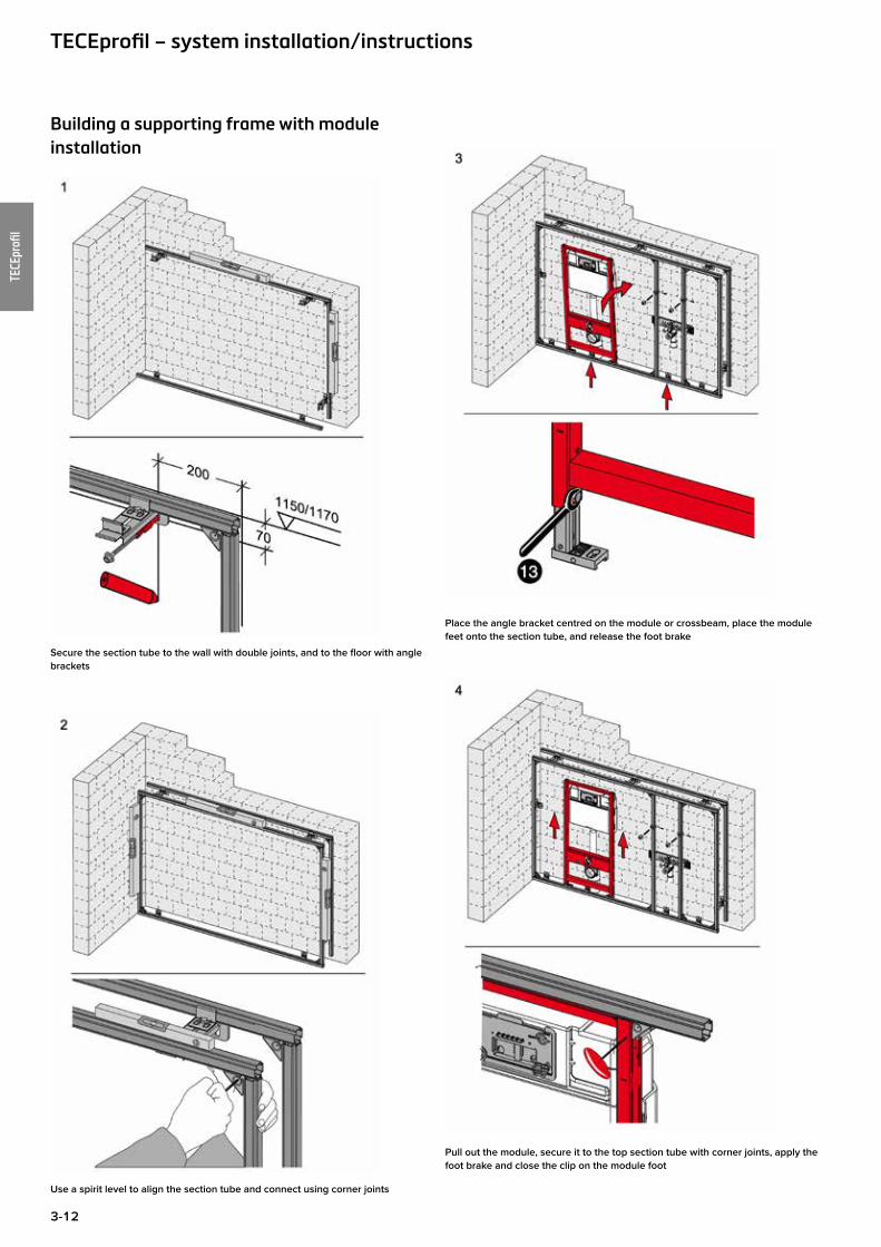
Building a supporting frame with module installation
Secure the section tube to the wall with double joints, and to the floor with angle brackets
Use a spirit level to align the section tube and connect using corner joints
Place the angle bracket centred on the module or crossbeam, place the module feet onto the section tube, and release the foot brake
Pull out the module, secure it to the top section tube with corner joints, apply the foot brake and close the clip on the module foot
TECEprofil – system installation/instructions
3-13
TECEprofi
l
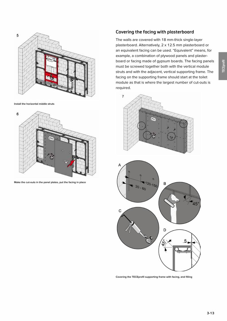
Install the horizontal middle struts
Make the cut-outs in the panel plates, put the facing in place
Covering the facing with plasterboard
The walls are covered with 18 mm-thick single-layer plasterboard. Alternatively, 2 x 12.5 mm plasterboard or an equivalent facing can be used. “Equivalent” means, for example, a combination of plywood panels and plaster-board or facing made of gypsum boards. The facing panels must be screwed together both with the vertical module struts and with the adjacent, vertical supporting frame. The facing on the supporting frame should start at the toilet module as that is where the largest number of cut-outs is required.
Covering the TECEprofil supporting frame with facing, and filling

3-14
TECEprofi
l
Practical tip:
The required cut-outs can be easily marked out using the marking plugs supplied. To do so, press the panelling against the marking plugs. The centre points of the cut-outs are now clearly marked.
Size of cut-outs for the toilet module
Size of cut-outs for the washstand module
Note:
The marking plugs are not suitable for a pressure test.
When applying panel facing, the general guidelines for dry-wall constructions must be taken into account. The joints in the covering must be filled with TECEprofil knifing filler. On non-ceramic surfaces, additional fibreglass joint ceiling strips must be used. The 5 mm gap between the structural shell and the facing must be filled and sealed with a permanently flexible compound. Cross joints (panels butted vertically and horizontally) must be avoided; the joints should be offset by at least 15 cm.
Joint patterns on the facing
Important: all abutting edges on the plasterboard must be chamfered to 45°.
TECEprofil – system installation/instructions
3-15
TECEprofi
l
Filling of plasterboard panels
When plasterboard panels are filled, a distinction must be made between four different levels of quality. Unless tender documents specify otherwise, quality level 1 gener-ally applies.
Quality level 1 covers the following requirements for filling:• filling of butted joints of plasterboard panels and• coating of the visible parts of the fastening elements
Any excess material must be removed. Markings, scratches and burrs caused by tools are permitted.
Further information about filler surface quality can be read in data sheet no. 2 of the German Gypsum Industry Asso-ciation.
TECEprofil knifing filler
TECEprofil knifing filler is a white powder to mix with water and is based on gypsum and PVA with methyl cellulose and cellulose reinforced fibre. It offers all the advantages of a quick plaster, has a very high adhesion and does not sink. TECEprofil knifing filler can be applied as thickly as required in one step, and hardens in the process without strain or cracks.
Application (indoor area)• Filling, plastering and smoothing of rough masonry,
plaster, concrete, filigree ceilings, aerated concrete and foamed concrete, sand-lime brick, plasterboard, fibre-re-inforced panels, light construction panels, and insulation panels.
• Filling the joints in plasterboard and gypsum fibreboard without fabric reinforcement. Take DIN 18181 + DIN 18183 and the processing guidelines of the board man-ufacturer into account. The site must be dry. On surfaces which are particularly subject to stress, e.g. in the area of installation openings, insert reinforcing strips if neces-sary.
• As an adhesive binder for securing plasterboard or gypsum fibreboard, expanded polystyrene and fibre-board panels to masonry in indoor areas. Absorbent sub-strates such as aerated concrete and sand-lime blocks must be primed first with penetrating primer/sealer.
• As a gypsum adhesive for non-load bearing gypsum partition wall panels.
SubstrateThe substrate must be clean, solid and offer maximum grip. Dirt, dust, wallpaper, old paint and plaster which is not adhering reliably must be removed. Pre-treat smooth, con-crete surfaces with a thinned plaster base; other smooth substrates such as gloss or emulsion paint must be pre-treated with a pigmented primer.
MixingPour clean water into a container and sprinkle in the powder (1 part water to approx. 2.25 parts powder). Stir vigorously until a very fine, smooth, paste-like compound is formed. To achieve the optimum working properties, wait for about 1–2 minutes and stir vigorously again.
Application tipsApply TECEprofil knifing filler evenly onto the substrate with a smoothing trowel.• can be worked for about 30 minutes without difficulty,• only use at temperatures above 8°C.
Post-treatmentIt is not generally necessary to post-treat the smoothed surfaces. However, if emulsion or gloss paint is applied, we recommend applying a coat of penetrating primer/sealer beforehand.

3-16
TECEprofi
l
Facing for highly wet areas
The TECEprofil panel for highly wet areas is a 12.5 mm-thick, cement-bound light concrete panel with a sand-wich structure, reinforced with a top layer of alkali-resistant fibreglass webbing on both sides. In areas where the walls are subject to a very high degree of moisture stress – such as in public shower facilities, swimming pools, fitness areas etc. – special facing panels must be used. For these areas, we recommended the use of especially durable and resistant water-repellent panelling material. The 12.5 mm-thick, cement-bound TECE facing panel for highly moisture-stressed areas fully meets these require-ments.
The design of dry-wall constructions in these areas is only partly covered by standards and directives:• For use in areas not regulated by the building author-
ities, the fundamental standard is the new information sheet “Bathrooms and wet rooms in wooden and dry-wall constructions” issued by the main associations and institutions for dry-wall constructions.
• For areas which are governed by the building authorities, the information sheet from the Central Association of the German Construction Industry (ZDB) applies.
Storage guidelines
Panel storage and transport:The panels are packed lying flat and delivered on pallets. They should always be stored lying flat on a smooth base. Storing them upright could distort the panels and damage the edges. If the panels are to be used to cover ceilings, the load-bearing capacity of the ceiling must be respected. Storage in the open air is possible because of the resist-ance to frost and water. However, because of their later surface handling, the panels should be provided with a water-repellent covering and protected from soiling by building work.
TECEprofil – system installation/instructions
Construction site conditions:As with all materials used in construction, fibreglass light concrete panels are subject to expansion and contraction due to the influence of temperature and moisture. The fol-lowing installation conditions must be adhered to in order to perform dry-wall work correctly:
• Only install fibreglass light concrete panels when the air humidity is less than 80%.
• Soaked panels must never be handled until they have completely dried out. Do not install damaged materials.
• Due to the technical process, bonding of fibreglass light concrete panels must be performed with air relative humidity < 80% and at a room and material temperature of at least+ 5°C.
• In the process the temperature of the adhesive must be > 10°C. The panels must have acclimatised to the condi-tions in the room because they must not change appreci-ably in the 12 hours following bonding.
• Low temperatures and high relative humidity prolong the hardening times. Heating using a gas torch can cause damage due to the risk of condensation being formed. This especially applies to indoor areas with poor ventila-tion. Sudden rapid heating should be avoided.
Cutting:Cement-bound lightweight concrete panels can be cut using a standard rail-guided portable circular saw with extraction, preferably as a plunge saw. To cut panels as exactly to size as possible and with sharp edges, we recommend using a saw blade with a smaller number of teeth. Cut-outs and curves can be cut conveniently using a jigsaw.
Panel facing:For the facing, TECEprofil walls can be covered with extremely robust fibreglass light concrete panels in a single layer construction. They should be installed with the noticeably smoother face to the front. Direct tiling is possible, depending on the application in question. With multi-layer facing, only the joints of the outer layer of facing panels need to be bonded together. Cross joints are not permitted. The offset of the joints between the panels must be at least 200 mm. For the purposes of good bonding, the panels must be cut absolutely straight and with sharp edges.
3-17
TECEprofi
l
Fixing:The fibreglass light concrete panels are secured to the TECE supporting frame using the same types of screw and with the same screw spacing as for the plasterboard panels. Pre-drilling is not necessary.
Joint technique:Differently to plasterboard, fibreglass light concrete panels are bonded to each other bluntly. Only Fermacell joint adhesive (order no. 9200014) is permitted for this purpose. About 20 ml of adhesive is required per metre. A 310 ml-cartridge will therefore bond about 15.5 m of panel joints. Apply the bead of adhesive to the edge of the panel. It is important that the adhesive completely fills the joint when the two panels are pressed together (the adhe-sive should be visible on the joint). The maximum width of the joint must not exceed 1 mm. To prevent disturbance to the film of adhesive during subsequent fixing and harden-ing, the joint should not be pressed down “into nothing”. Depending on room temperature and humidity, the adhe-sive is set after about 12–36 hours. Afterwards the excess adhesive is completely removed. This can be done using a putty knife or a scraper.
Job steps for moisture stress class A (high degree of wetness)
In moisture stress class A areas, the whole surface of the facing panels must be sealed with a sealing system (includ-ing the flexible adhesive).For sealing systems in the remaining moisture stress classes, please refer directly to the manufacturers of build-ing chemical products.
Work steps required:
1. Bond the abutting edges
2. Remove excess joint adhesive after it has set
3. Fill the visible fastening material using fine filler or skim coating
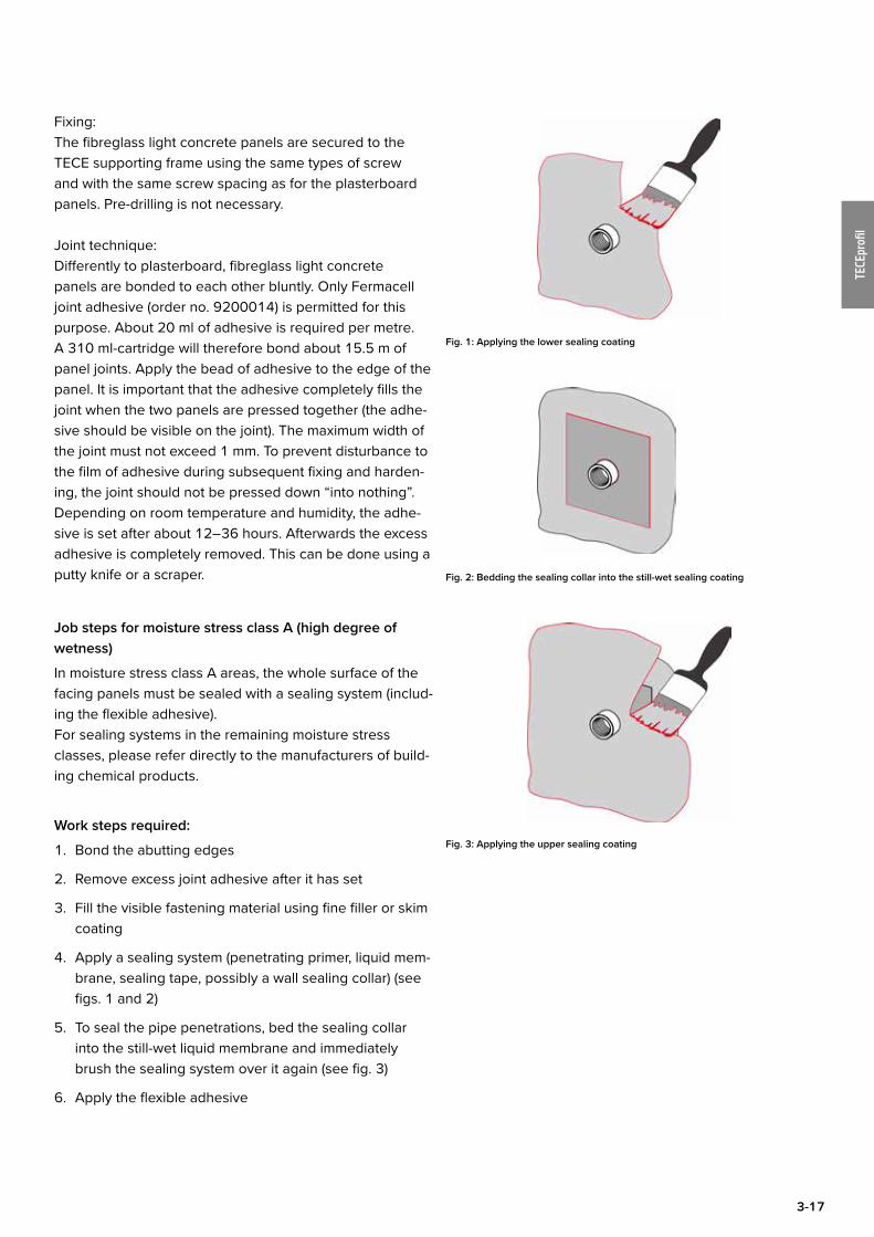
4. Apply a sealing system (penetrating primer, liquid mem-brane, sealing tape, possibly a wall sealing collar) (see figs. 1 and 2)
5. To seal the pipe penetrations, bed the sealing collar into the still-wet liquid membrane and immediately brush the sealing system over it again (see fig. 3)
6. Apply the flexible adhesive
Fig. 1: Applying the lower sealing coating
Fig. 2: Bedding the sealing collar into the still-wet sealing coating
Fig. 3: Applying the upper sealing coating

3-18
TECEprofi
l
Possible pre-wall heights and depths
Possible pre-wall depths with TECEprofil supporting frame
Possible pre-wall heights with TECEprofil supporting frame – 1
Order no. Standard
height
T1
min.
T2
min.
930000093000039300007930001193000339300044
1,150(1,120–1,350)
160 210
9300022 980–1,080 160 210
9300001 820-920 160 210
9041006 970-1,350 160 210
93100009310004
1,150(1,120–1,350
140 (115
210
902003390200189020034
820–1,350 140 (115
210
9320002932000093200019020017
1,150(1,120–1,350)
140 (115
170
9330000 1,150(1,120–1,350)
140 (115
210
Possible pre-wall heights with TECEprofil supporting frame – 2
TECEprofil – system installation/instructions
3-19
TECEprofi
l
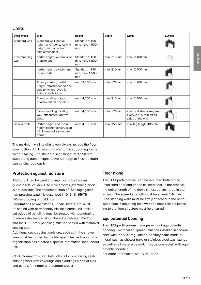
Limits
Designation Type Height Depth Width Symbol
Standard wall Standard wall, partial height and floor-to-ceiling height, with or without side attachment
Standard 1,150 mm, max. 4,500 mm
- -
Free-standing wall
partial height, without side attachment
Standard 1,150 mm, max. 1,500 mm
min. 210 mm max. 2,400 mm
partial height, attachment on one side
Standard 1,150 mm, max. 1,500 mm
min. 210 mm max. 2,400 mm
Privacy screen, partial height, attachment on one side (only approved for fitting installations)
max. 2,000 mm min. 170 mm max. 1,200 mm
floor-to-ceiling height, attachment on one side
max. 4,500 mm min. 210 mm max. 2,400 mm
Floor-to-ceiling dividing wall, attachment on two sides
max. 4,500 mm min. 170 mm a vertical strut is required every 2,400 mm on all sides of the wall.
Special wall Partial height and room height corner construction 45° in front of a structural corner
max. 4,500 mm min. 350 mm min. leg length 495 mm
The maximum wall heights given always include the floor construction. All dimensions refer to the supporting frame without facing. The standard shelf height of 1,150 mm (supporting frame height above top edge of finished floor) can be changed easily.
Protection against moisture
TECEprofil can be used in damp rooms (bathrooms, guest toilets, cellars). Use in wet rooms (swimming pools) is not possible. The implementation of “Sealing against non-pressing water” is described in DIN 18195/T5 “Water-proofing of buildings”.Penetrations at washstands, urinals, bidets, etc. must be sealed with permanently elastic material. All unfilled cut edges of panelling must be treated with penetrating primer/sealer before tiling. The edge between the floor and the TECEprofil panelling must be sealed with standard sealing tape.Additional seals against moisture, such as in the shower area must be formed by the tile layer. The tile laying trade organisation has created a special information sheet about this.
(ZDB information sheet: Instructions for processing seal-ants together with coverings and claddings made of tiles and panels for indoor and outdoor areas)
Floor fixing
The TECEprofil pre-wall can be mounted both on the unfinished floor and on the finished floor. In the process, the entire length of the dowels must be anchored in the screed. The screed strength must be at least 5 N/mm2. Free-standing walls must be firmly attached to the unfin-ished floor. If mounting on a wooden floor, reliable fasten-ing to the floor structure must be ensured.
Equipotential bonding
The TECEprofil system manages without equipotential bonding. Electrical equipment must be installed in accord-ance with the VDE regulations. Sanitary items made of metal, such as shower trays or stainless steel washstands as well as all metal pipework must be connected with equi-potential bonding. For more information, see: VDE 0100.
3-20
TECEprofi
l
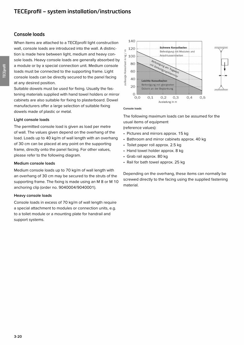
Console loads
When items are attached to a TECEprofil light construction wall, console loads are introduced into the wall. A distinc-tion is made here between light, medium and heavy con-sole loads. Heavy console loads are generally absorbed by a module or by a special connection unit. Medium console loads must be connected to the supporting frame. Light console loads can be directly secured to the panel facing at any desired position. Suitable dowels must be used for fixing. Usually the fas-tening materials supplied with hand towel holders or mirror cabinets are also suitable for fixing to plasterboard. Dowel manufacturers offer a large selection of suitable fixing dowels made of plastic or metal.
Light console loads
The permitted console load is given as load per metre of wall. The values given depend on the overhang of the load. Loads up to 40 kg/m of wall length with an overhang of 30 cm can be placed at any point on the supporting frame, directly onto the panel facing. For other values, please refer to the following diagram.
Medium console loads
Medium console loads up to 70 kg/m of wall length with an overhang of 30 cm may be secured to the struts of the supporting frame. The fixing is made using an M 8 or M 10 anchoring clip (order no. 9040004/9040001).
Heavy console loads
Console loads in excess of 70 kg/m of wall length require a special attachment to modules or connection units, e.g. to a toilet module or a mounting plate for handrail and support systems.
Console loads
The following maximum loads can be assumed for the usual items of equipment (reference values): • Pictures and mirrors approx. 15 kg• Bathroom and mirror cabinets approx. 40 kg• Toilet paper roll approx. 2.5 kg • Hand towel holder approx. 8 kg• Grab rail approx. 80 kg • Rail for bath towel approx. 25 kg
Depending on the overhang, these items can normally be screwed directly to the facing using the supplied fastening material.
TECEprofil – system installation/instructions
3-21
TECEprofi
l
TECEprofil universal moduleThe TECEprofil universal module is an all-rounder. Only one module is required for all current dry-wall construc-tions. This saves storage space and makes calculation and logistics easier.
Example
The TECEprofil universal module with TECE concealed cistern:
Toilet universal module, assembly height 1120 mm
• Clearly visible: installation mark.• Robust, self-supporting mounting frame. All toilet mod-
ules are statically self-supporting and can withstand a max. load of 400 kg. Holes in the crossbeam enable shower toilet connections to be upgraded.
• Pilot holes for mounting in UA-profile walls and wooden stud walls.
• Strong crossbeam with four threaded holes for ceramics with a mounting distance of 180 or 230 mm. The cross-beam ensures that the ceramic is safely secured even under high loads.
• Optional retainers for additional supports for ceramics with a reduced supporting surface.
• Integrated foot brake facilitates height adjustment.• Adjustable foot supports for floor construction of 0 to
200 mm. For attaching to the floor or on a TECEprofil rail.• Two-part DN 90/100 toilet drain bend. This allows DN 90
and DN 100 wastewater pipes to be connected easily. The DN 90/100 adapter can also be individually installed as a horizontal outflow in the module. Downpipes behind the module are then easy to connect directly.
• Many upgrade options such as wooden panels for hold-ing safety support arms, shower toilet solutions, corner installations, and many more.
Using universal module technology increases the possible areas of installation:• in a TECEprofil pre-wall• in front of a solid wall• in a C-profile wall• in a UA-profile wall• in a wooden stud wall
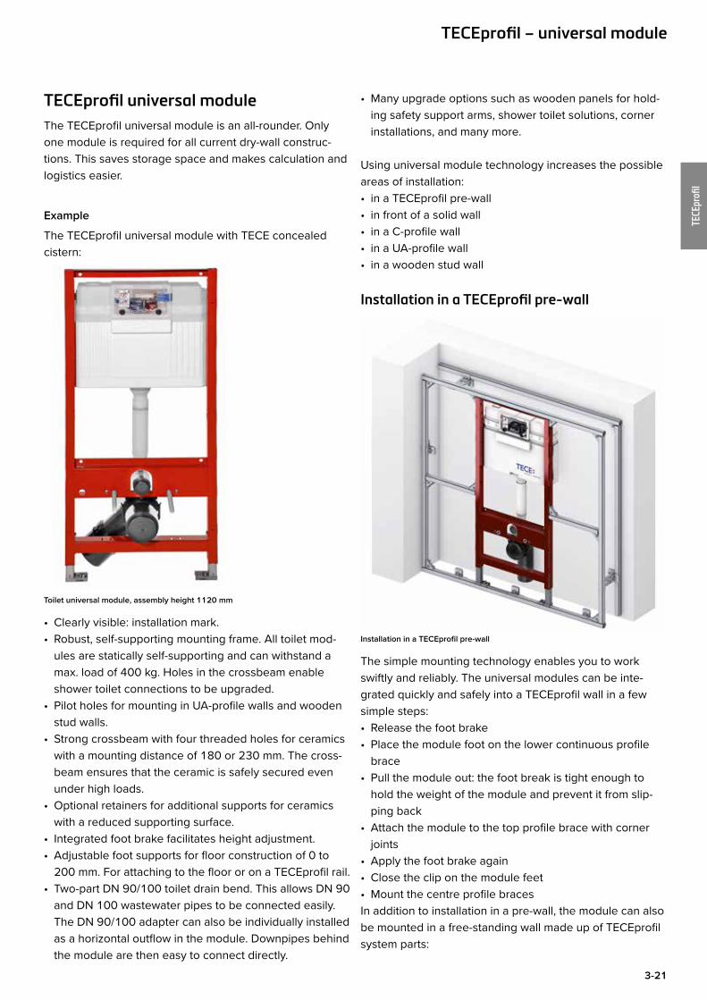
Installation in a TECEprofil pre-wall
Installation in a TECEprofil pre-wall
The simple mounting technology enables you to work swiftly and reliably. The universal modules can be inte-grated quickly and safely into a TECEprofil wall in a few simple steps:• Release the foot brake• Place the module foot on the lower continuous profile
brace• Pull the module out: the foot break is tight enough to
hold the weight of the module and prevent it from slip-ping back
• Attach the module to the top profile brace with corner joints
• Apply the foot brake again• Close the clip on the module feet• Mount the centre profile bracesIn addition to installation in a pre-wall, the module can also be mounted in a free-standing wall made up of TECEprofil system parts:
TECEprofil – universal module

3-22
TECEprofi
l
Installation in a free-standing TECEprofil wall
Installation in front of a solid wall
TECEprofil universal modules are also suitable for indi-vidual installation. Compatible attachments are available for various installation situations. The universal module is statically designed so that, in standard cases, it only has to be attached to the load-bearing structural shell at four points. Additional attachments such as elbow brackets are only necessary where high loads are involved (e.g. bar-rier-free toilet facilities). The mounting material supplied with the attachment units is suitable for mounting on solid walls. Use suitable cavity plugs when mounting in front of lightweight partition walls. The partition wall should also be reinforced at the mounting points. The procedure should be followed in line with the dry-wall construction.Take into account the installation instructions for the dry-wall system used.
Individual module installation with depth-adjustable uni-versal attachment (order number 9380000):
Individual mounting with depth-adjustable universal attachments
The universal module is placed directly against the wall. The pre-wall depth can be adjusted using the universal attachments. The module's height can be adjusted by means of the extractable module feet. The foot brake prevents the module from sinking down. In this way, the module can be accurately positioned before the module feet and universal attachments are attached to the struc-ture.
Universal attachment 9380000
Adjustment range of universal attachment 150 – 240 mm
TECEprofil – universal module
3-23
TECEprofi
l
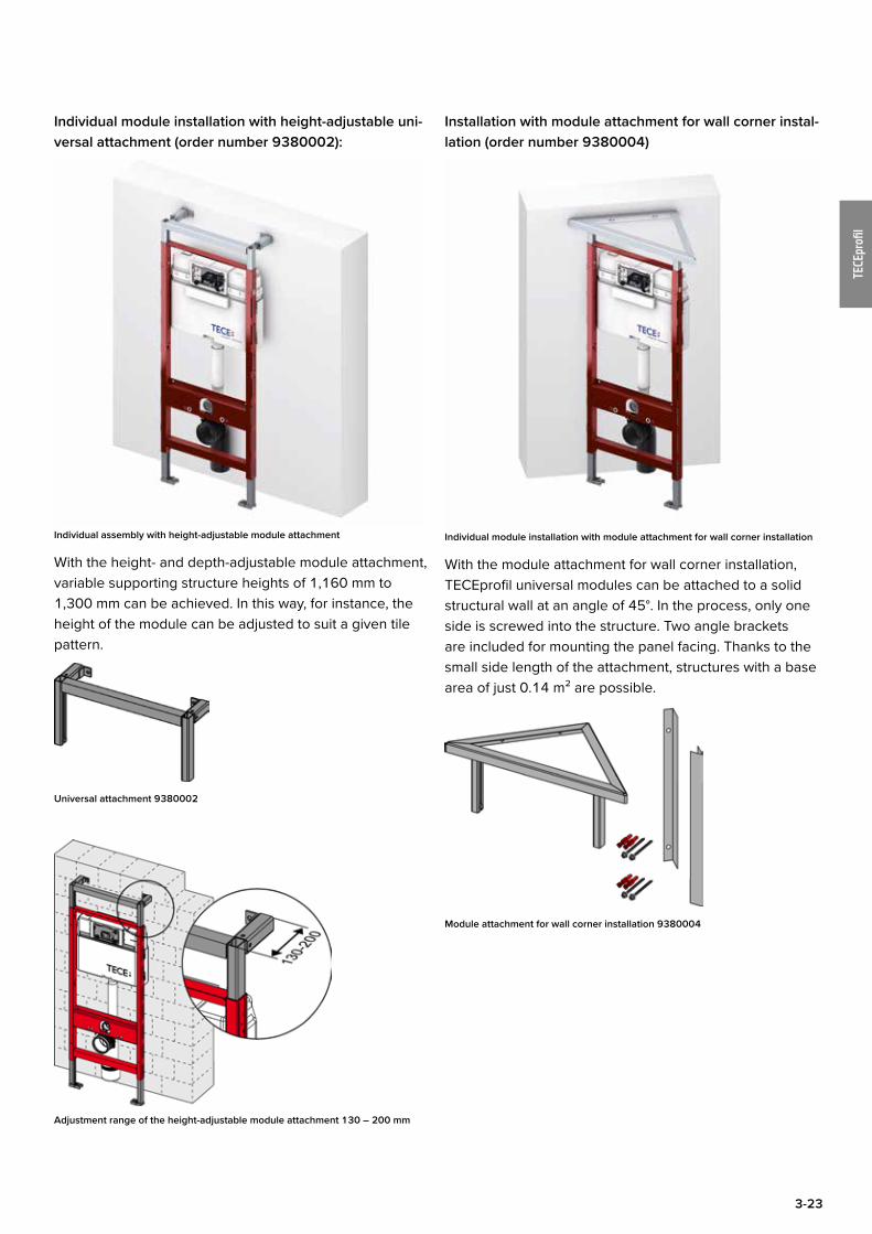
Individual module installation with height-adjustable uni-versal attachment (order number 9380002):
Individual assembly with height-adjustable module attachment
With the height- and depth-adjustable module attachment, variable supporting structure heights of 1,160 mm to 1,300 mm can be achieved. In this way, for instance, the height of the module can be adjusted to suit a given tile pattern.
Universal attachment 9380002
Adjustment range of the height-adjustable module attachment 130 – 200 mm
Installation with module attachment for wall corner instal-lation (order number 9380004)
Individual module installation with module attachment for wall corner installation
With the module attachment for wall corner installation, TECEprofil universal modules can be attached to a solid structural wall at an angle of 45°. In the process, only one side is screwed into the structure. Two angle brackets are included for mounting the panel facing. Thanks to the small side length of the attachment, structures with a base area of just 0.14 m² are possible.
Module attachment for wall corner installation 9380004
3-24
TECEprofi
l
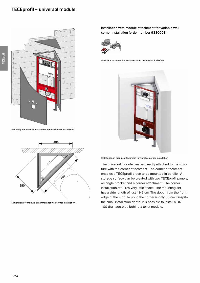
Mounting the module attachment for wall corner installation
Dimensions of module attachment for wall corner installation
Installation with module attachment for variable wall corner installation (order number 9380003)
Module attachment for variable corner installation 9380003
Installation of module attachment for variable corner installation
The universal module can be directly attached to the struc-ture with the corner attachment. The corner attachment enables a TECEprofil brace to be mounted in parallel. A storage surface can be created with two TECEprofil panels, an angle bracket and a corner attachment. The corner installation requires very little space. The mounting set has a side length of just 49.5 cm. The depth from the front edge of the module up to the corner is only 35 cm. Despite the small installation depth, it is possible to install a DN 100 drainage pipe behind a toilet module.
TECEprofil – universal module
3-25
TECEprofi
l
Dimensions of module attachment for variable corner installation
Installation examples with module attachments for variable corner installations
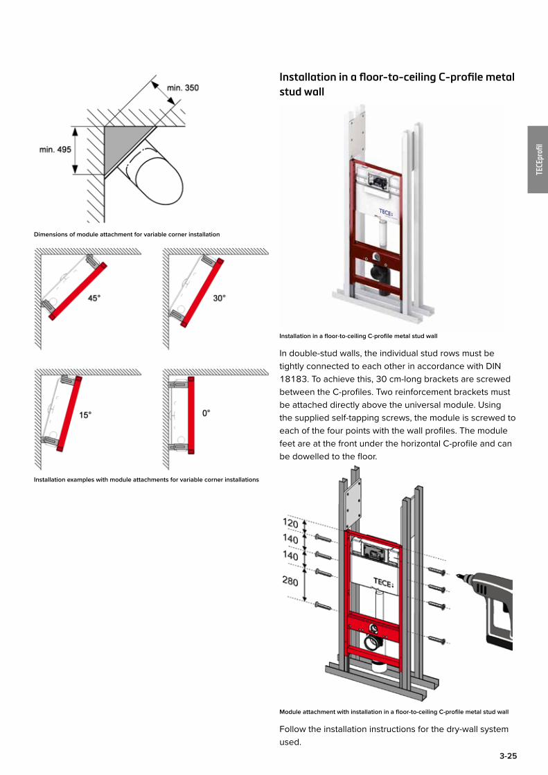
Installation in a floor-to-ceiling C-profile metal stud wall
Installation in a floor-to-ceiling C-profile metal stud wall
In double-stud walls, the individual stud rows must be tightly connected to each other in accordance with DIN 18183. To achieve this, 30 cm-long brackets are screwed between the C-profiles. Two reinforcement brackets must be attached directly above the universal module. Using the supplied self-tapping screws, the module is screwed to each of the four points with the wall profiles. The module feet are at the front under the horizontal C-profile and can be dowelled to the floor.
Module attachment with installation in a floor-to-ceiling C-profile metal stud wall
Follow the installation instructions for the dry-wall system used.

3-26
TECEprofi
l
Installation in floor-to-ceiling metal stud wall with UA-profiles
Installation in a floor-to-ceiling UA-profile metal stud wall
If particularly wide or high walls have a higher rigidity, UA-profiles (DIN 18182 part 1) can be used instead of C-profiles. This measure is only relevant for toilet and bidet modules.
For a disabled toilet facility only UA-profiles may be used for the front and rear struts for strength reasons. The instal-lation of toilet facilities in public places for disabled and elderly people must be carried out in accordance with DIN 18040-1.
Module attachment with installation in a floor-to-ceiling UA-profile metal stud wall
Due to the prescribed seat height of 48 cm, the universal module must be mounted 5 cm higher than the standard installation height. TECEprofil universal modules have pre-drilled holes in the side struts for attaching universal mod-ules to the UA50 profiles. The holes are arranged so that there are at least two possible mounting options per strut.
TECEprofil – universal module
3-27
TECEprofi
l
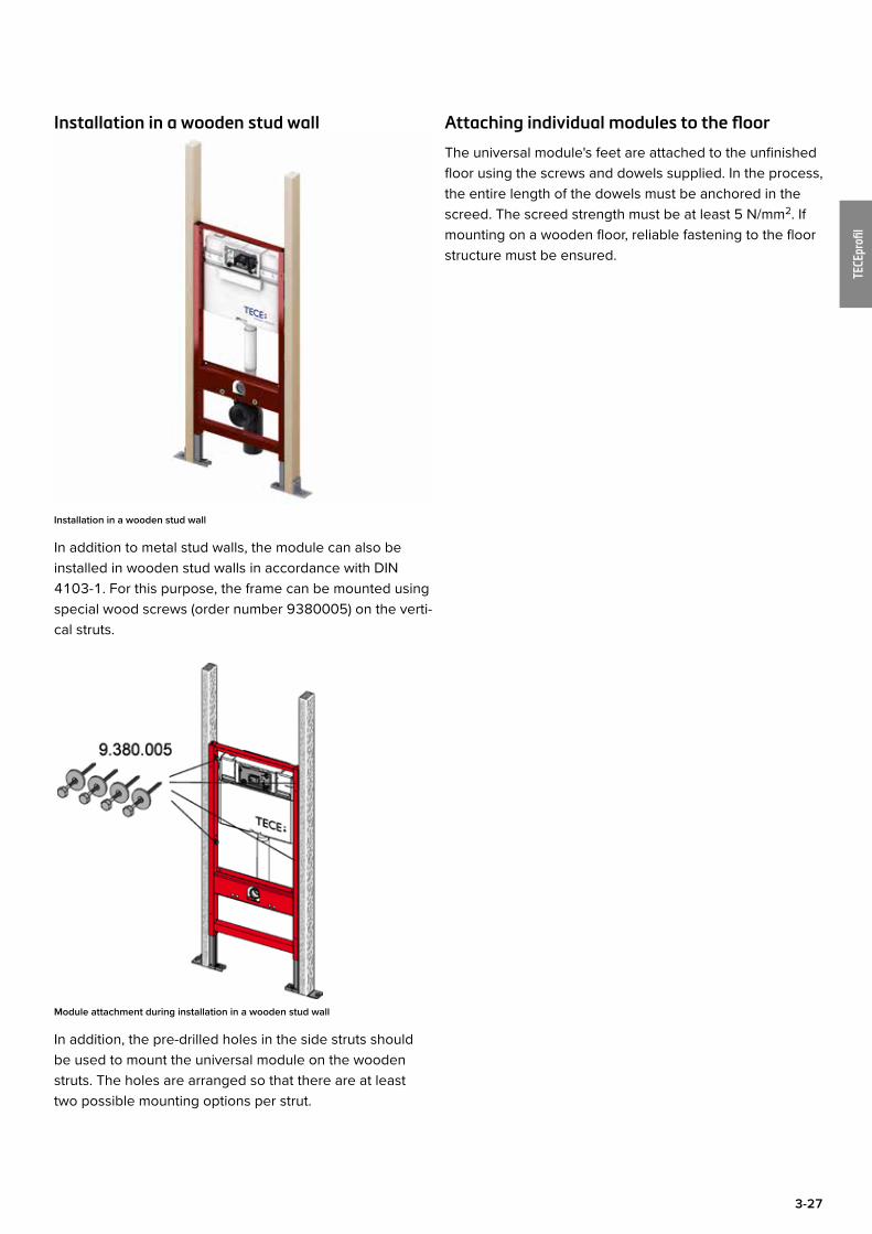
Installation in a wooden stud wall
Installation in a wooden stud wall
In addition to metal stud walls, the module can also be installed in wooden stud walls in accordance with DIN 4103-1. For this purpose, the frame can be mounted using special wood screws (order number 9380005) on the verti-cal struts.
Module attachment during installation in a wooden stud wall
In addition, the pre-drilled holes in the side struts should be used to mount the universal module on the wooden struts. The holes are arranged so that there are at least two possible mounting options per strut.
Attaching individual modules to the floor
The universal module's feet are attached to the unfinished floor using the screws and dowels supplied. In the process, the entire length of the dowels must be anchored in the screed. The screed strength must be at least 5 N/mm2. If mounting on a wooden floor, reliable fastening to the floor structure must be ensured.
3-28
TECEprofi
l
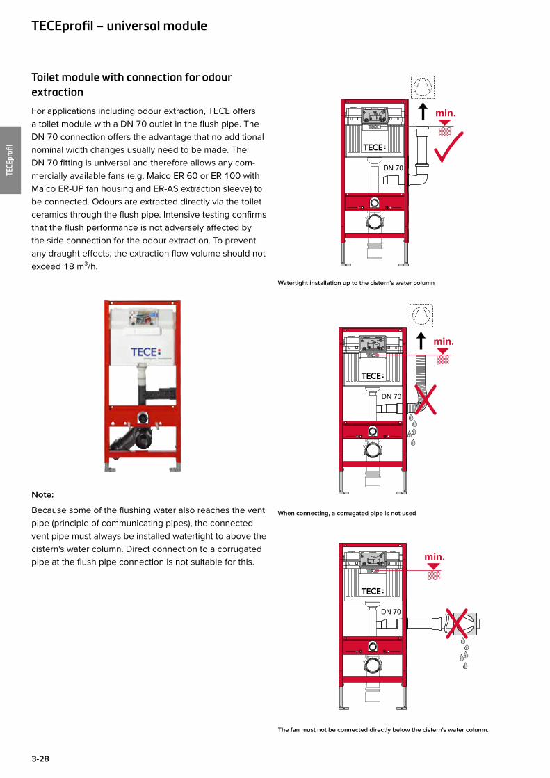
Toilet module with connection for odour extraction
For applications including odour extraction, TECE offers a toilet module with a DN 70 outlet in the flush pipe. The DN 70 connection offers the advantage that no additional nominal width changes usually need to be made. The DN 70 fitting is universal and therefore allows any com-mercially available fans (e.g. Maico ER 60 or ER 100 with Maico ER-UP fan housing and ER-AS extraction sleeve) to be connected. Odours are extracted directly via the toilet ceramics through the flush pipe. Intensive testing confirms that the flush performance is not adversely affected by the side connection for the odour extraction. To prevent any draught effects, the extraction flow volume should not exceed 18 m³/h.
Note:
Because some of the flushing water also reaches the vent pipe (principle of communicating pipes), the connected vent pipe must always be installed watertight to above the cistern's water column. Direct connection to a corrugated pipe at the flush pipe connection is not suitable for this.
Watertight installation up to the cistern's water column
When connecting, a corrugated pipe is not used
The fan must not be connected directly below the cistern's water column.
TECEprofil – universal module

3-29
TECEprofi
l
Multi-storey dwelling:
In toilet areas without an outside wall in multi-storey dwell-ings, the toilet element can be easily connected to the room fan. This is achieved using the existing DN 70 con-nection sleeve, which permits connection to the concealed housing with a second room connection via plastic pipes. The large cross-section of 70 mm ensures a low air veloc-ity and permits effective, draught-free odour extraction. The moisture in the extracted air condenses on the inner wall of the air extraction pipe before it reaches the fan.
Detached house:
The toilet element with odour extraction can also be used in a detached house. If the bathroom has an outside wall, the extraction pipe from the toilet element is connected to an in-duct fan. Odour extraction can therefore be easily implemented, without adverse effects such as a tempera-ture drop caused by opening a window, which in turn leads to higher heating costs.
Installation examples:
Note:
Odour extraction is possible for all conventional toilet ceramics. However, in some ceramics which have a higher seat position or higher flushing rim, the flushing water remains standing in the flush pipe, resulting in the bowl becoming partially or completely full. The following table lists the ceramics for which the use of the odour extraction is not possible:
Manufacturer Product Item no.Catalano Zero 1VSxxN00Duravit Strength 1 021009
Strength 3 221509Architec (Duraplus) 254609
Ideal Standard Mia/SimplyU J4521xxSoftMood T3226xxVentuno standing toilet T3161xx
Keramag 4U RimFree 203460500 by Citterio - tief 202100CASSINI - tief 203200EMANI by Citterio - tief 207800ERA - tief 208800It! RimFree 201950Plus 4 202010Silk - flach 203670Visit 2063xx
Laufen LP3 20681Villeroy & Boch Omnia classic 66 65 10
Omnia O.novo 66 95 10
3-30
TECEprofi
l
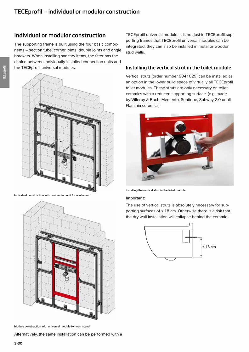
Individual or modular constructionThe supporting frame is built using the four basic compo-nents – section tube, corner joints, double joints and angle brackets. When installing sanitary items, the fitter has the choice between individually-installed connection units and the TECEprofil universal modules.
Individual construction with connection unit for washstand
Module construction with universal module for washstand
Alternatively, the same installation can be performed with a
TECEprofil universal module. It is not just in TECEprofil sup-porting frames that TECEprofil universal modules can be integrated, they can also be installed in metal or wooden stud walls.
Installing the vertical strut in the toilet module
Vertical struts (order number 9041029) can be installed as an option in the lower build space of virtually all TECEprofil toilet modules. These struts are only necessary on toilet ceramics with a reduced supporting surface. (e.g. made by Villeroy & Boch: Memento, Sentique, Subway 2.0 or all Flaminia ceramics).
Installing the vertical strut in the toilet module
Important:
The use of vertical struts is absolutely necessary for sup-porting surfaces of < 18 cm. Otherwise there is a risk that the dry wall installation will collapse behind the ceramic.
TECEprofil – individual or modular construction
3-31
TECEprofi
l
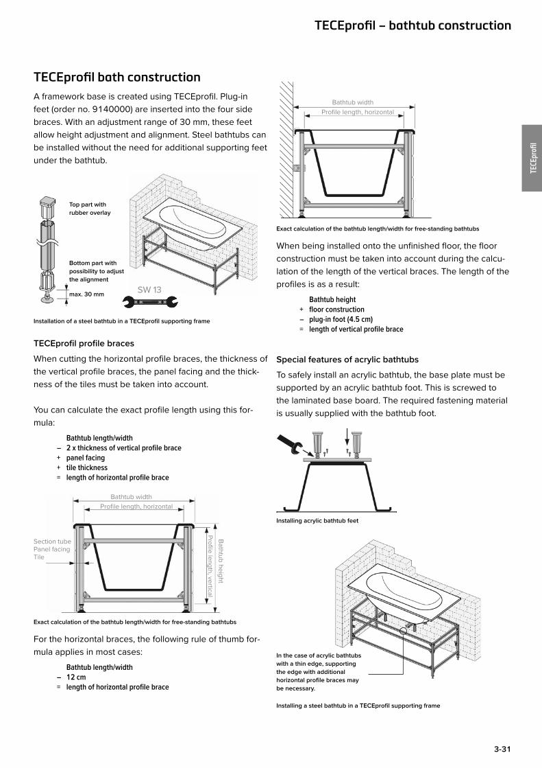
TECEprofil bath constructionA framework base is created using TECEprofil. Plug-in feet (order no. 9140000) are inserted into the four side braces. With an adjustment range of 30 mm, these feet allow height adjustment and alignment. Steel bathtubs can be installed without the need for additional supporting feet under the bathtub.
Top part with rubber overlay
Bottom part with possibility to adjustthe alignment
max. 30 mm SW 13
Installation of a steel bathtub in a TECEprofil supporting frame
TECEprofil profile braces
When cutting the horizontal profile braces, the thickness of the vertical profile braces, the panel facing and the thick-ness of the tiles must be taken into account.
You can calculate the exact profile length using this for-mula:
Bathtub length/width – 2 x thickness of vertical profile brace + panel facing + tile thickness = length of horizontal profile brace
Bathtub heightProfile length, vertical
Section tubePanel facingTile
Bathtub widthProfile length, horizontal
Exact calculation of the bathtub length/width for free-standing bathtubs
For the horizontal braces, the following rule of thumb for-mula applies in most cases:
Bathtub length/width – 12 cm = length of horizontal profile brace
Bathtub widthProfile length, horizontal
Exact calculation of the bathtub length/width for free-standing bathtubs
When being installed onto the unfinished floor, the floor construction must be taken into account during the calcu-lation of the length of the vertical braces. The length of the profiles is as a result:
Bathtub height + floor construction – plug-in foot (4.5 cm) = length of vertical profile brace
Special features of acrylic bathtubs
To safely install an acrylic bathtub, the base plate must be supported by an acrylic bathtub foot. This is screwed to the laminated base board. The required fastening material is usually supplied with the bathtub foot.
Installing acrylic bathtub feet
In the case of acrylic bathtubs with a thin edge, supporting the edge with additional horizontal profile braces may be necessary.
Installing a steel bathtub in a TECEprofil supporting frame
TECEprofil – bathtub construction
3-32
TECEprofi
l
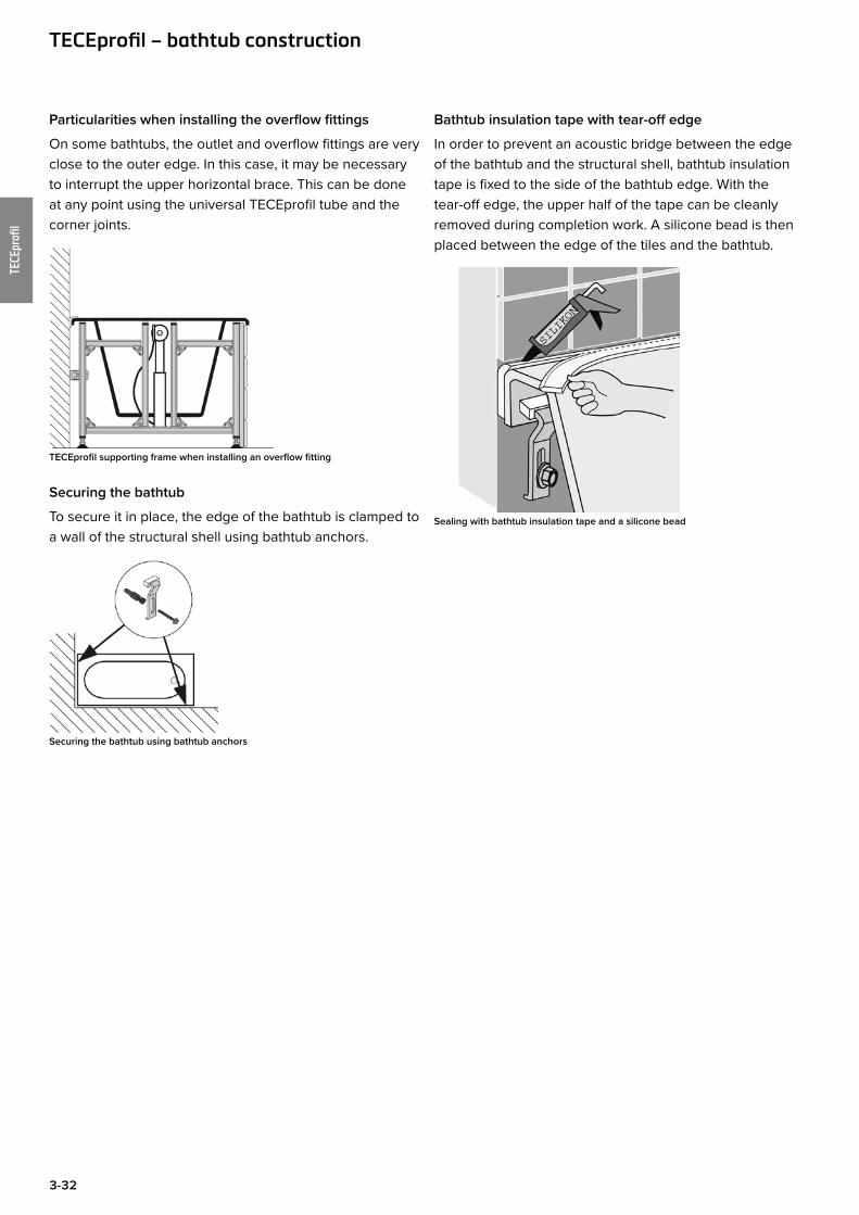
Particularities when installing the overflow fittings
On some bathtubs, the outlet and overflow fittings are very close to the outer edge. In this case, it may be necessary to interrupt the upper horizontal brace. This can be done at any point using the universal TECEprofil tube and the corner joints.
TECEprofil supporting frame when installing an overflow fitting
Securing the bathtub
To secure it in place, the edge of the bathtub is clamped to a wall of the structural shell using bathtub anchors.
Securing the bathtub using bathtub anchors
Bathtub insulation tape with tear-off edge
In order to prevent an acoustic bridge between the edge of the bathtub and the structural shell, bathtub insulation tape is fixed to the side of the bathtub edge. With the tear-off edge, the upper half of the tape can be cleanly removed during completion work. A silicone bead is then placed between the edge of the tiles and the bathtub.
Sealing with bathtub insulation tape and a silicone bead
TECEprofil – bathtub construction
3-33
TECEprofi
l
Bath
tub
leng
th L
Bath
tub
widt
h B
Sect
ion
tube
90
0000
0
Corn
er jo
int
9 01
0 00
2
Angl
e br
acke
t 90
3000
2
doub
le jo
int
9030
011
Unive
rsal
atta
chm
ent
9018
002
Fitti
ng co
nnec
tion
cros
sbea
m
9020
035
Plug
-in fo
ot
9140
000
Bath
tub
anch
or
Bath
tub
insu
latio
n ta
pe
Facin
g ar
ea
9200
000
m m m Unit Unit Unit Unit Unit Unit Unit m m2
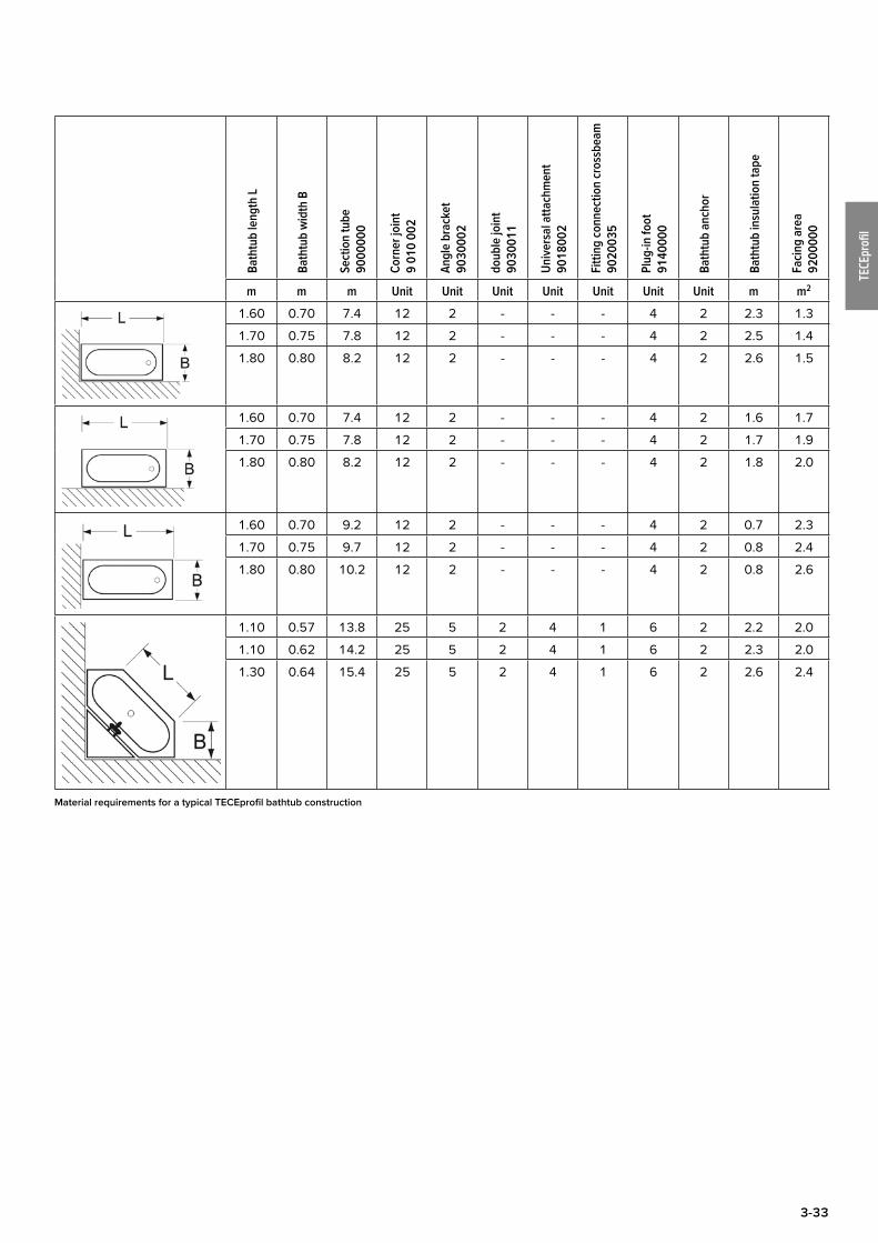
1.60 0.70 7.4 12 2 - - - 4 2 2.3 1.3
1.70 0.75 7.8 12 2 - - - 4 2 2.5 1.4
1.80 0.80 8.2 12 2 - - - 4 2 2.6 1.5
1.60 0.70 7.4 12 2 - - - 4 2 1.6 1.7
1.70 0.75 7.8 12 2 - - - 4 2 1.7 1.9
1.80 0.80 8.2 12 2 - - - 4 2 1.8 2.0
1.60 0.70 9.2 12 2 - - - 4 2 0.7 2.3
1.70 0.75 9.7 12 2 - - - 4 2 0.8 2.4
1.80 0.80 10.2 12 2 - - - 4 2 0.8 2.6
1.10 0.57 13.8 25 5 2 4 1 6 2 2.2 2.0
1.10 0.62 14.2 25 5 2 4 1 6 2 2.3 2.0
1.30 0.64 15.4 25 5 2 4 1 6 2 2.6 2.4
Material requirements for a typical TECEprofil bathtub construction
3-34
TECEprofi
l
Shower toilet solutionsShower toilet solutions are becoming increasingly popu-lar. Modern shower toilets combine toilet and bidet tech-nology. Thanks to universal module technology and the upgrade set for modules, TECE makes it possible to install the most modern shower toilet solutions on the market.
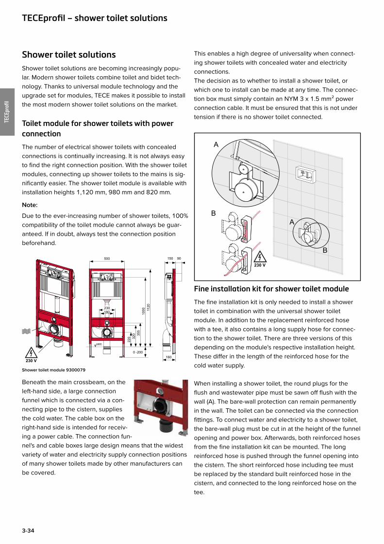
Toilet module for shower toilets with power connection
The number of electrical shower toilets with concealed connections is continually increasing. It is not always easy to find the right connection position. With the shower toilet modules, connecting up shower toilets to the mains is sig-nificantly easier. The shower toilet module is available with installation heights 1,120 mm, 980 mm and 820 mm.
Note:
Due to the ever-increasing number of shower toilets, 100% compatibility of the toilet module cannot always be guar-anteed. If in doubt, always test the connection position beforehand.
OKFF
160
150 90
0 -200
500
1120
1000
355
320
220
180230
230 V
Shower toilet module 9300079
Beneath the main crossbeam, on the left-hand side, a large connection funnel which is connected via a con-necting pipe to the cistern, supplies the cold water. The cable box on the right-hand side is intended for receiv-ing a power cable. The connection fun-nel's and cable boxes large design means that the widest variety of water and electricity supply connection positions of many shower toilets made by other manufacturers can be covered.
This enables a high degree of universality when connect-ing shower toilets with concealed water and electricity connections.The decision as to whether to install a shower toilet, or which one to install can be made at any time. The connec-tion box must simply contain an NYM 3 x 1.5 mm² power connection cable. It must be ensured that this is not under tension if there is no shower toilet connected.
Fine installation kit for shower toilet module
The fine installation kit is only needed to install a shower toilet in combination with the universal shower toilet module. In addition to the replacement reinforced hose with a tee, it also contains a long supply hose for connec-tion to the shower toilet. There are three versions of this depending on the module's respective installation height. These differ in the length of the reinforced hose for the cold water supply.
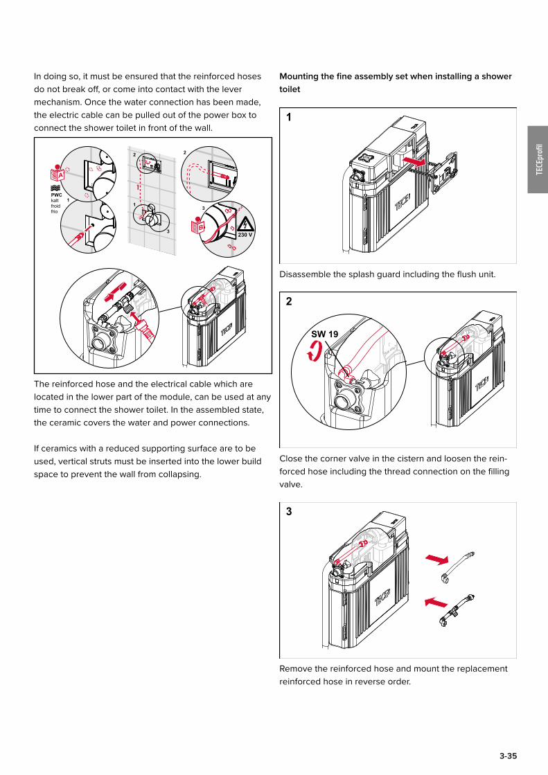
When installing a shower toilet, the round plugs for the flush and wastewater pipe must be sawn off flush with the wall (A). The bare-wall protection can remain permanently in the wall. The toilet can be connected via the connection fittings. To connect water and electricity to a shower toilet, the bare-wall plug must be cut in at the height of the funnel opening and power box. Afterwards, both reinforced hoses from the fine installation kit can be mounted. The long reinforced hose is pushed through the funnel opening into the cistern. The short reinforced hose including tee must be replaced by the standard built reinforced hose in the cistern, and connected to the long reinforced hose on the tee.
A
B
A
B
230 V
TECEprofil – shower toilet solutions
3-35
TECEprofi
l
In doing so, it must be ensured that the reinforced hoses do not break off, or come into contact with the lever mechanism. Once the water connection has been made, the electric cable can be pulled out of the power box to connect the shower toilet in front of the wall.
11
2 2
3
3
230 VB
A
PWCkalt froidfrio
The reinforced hose and the electrical cable which are located in the lower part of the module, can be used at any time to connect the shower toilet. In the assembled state, the ceramic covers the water and power connections.
If ceramics with a reduced supporting surface are to be used, vertical struts must be inserted into the lower build space to prevent the wall from collapsing.
Mounting the fine assembly set when installing a shower toilet
1
Disassemble the splash guard including the flush unit.
2
SW 19
Close the corner valve in the cistern and loosen the rein-forced hose including the thread connection on the filling valve.
3
Remove the reinforced hose and mount the replacement reinforced hose in reverse order.
3-36
TECEprofi
l
4
SW 19
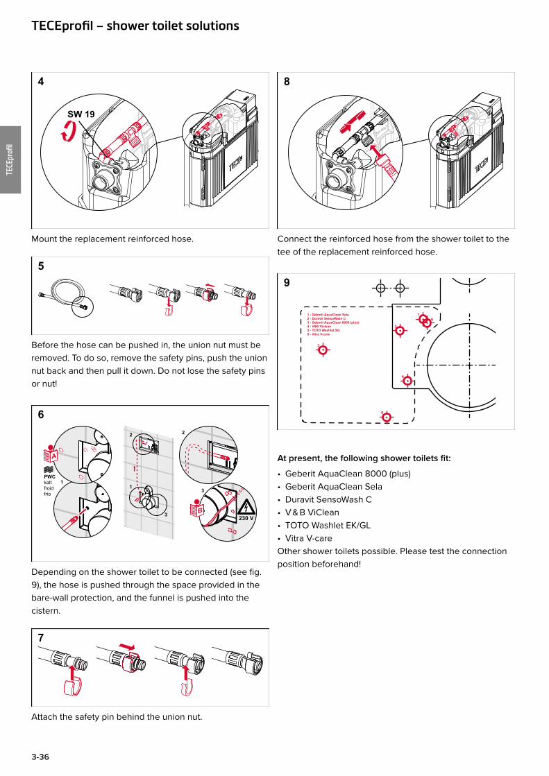
Mount the replacement reinforced hose.
5
Before the hose can be pushed in, the union nut must be removed. To do so, remove the safety pins, push the union nut back and then pull it down. Do not lose the safety pins or nut!
6
11
2 2
3
3
230 VB
A
PWCkalt froidfrio
Depending on the shower toilet to be connected (see fig. 9), the hose is pushed through the space provided in the bare-wall protection, and the funnel is pushed into the cistern.
7
Attach the safety pin behind the union nut.
8
Connect the reinforced hose from the shower toilet to the tee of the replacement reinforced hose.
9
1 - Geberit AquaClean Sela2 - Duravit SensoWash C3 - Geberit AquaClean 8000 (plus)4 - V&B Viclean5 - TOTO Washlet SG6 - Vitra V-care
1
2
3
4
5
6
At present, the following shower toilets fit:
• Geberit AquaClean 8000 (plus)• Geberit AquaClean Sela• Duravit SensoWash C• V & B ViClean• TOTO Washlet EK/GL• Vitra V-careOther shower toilets possible. Please test the connection position beforehand!
TECEprofil – shower toilet solutions
3-37
TECEprofi
l
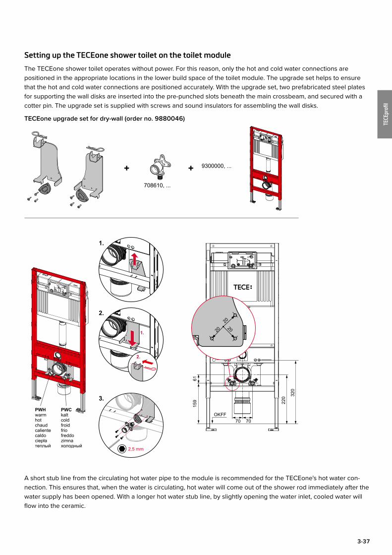
Setting up the TECEone shower toilet on the toilet module
The TECEone shower toilet operates without power. For this reason, only the hot and cold water connections are positioned in the appropriate locations in the lower build space of the toilet module. The upgrade set helps to ensure that the hot and cold water connections are positioned accurately. With the upgrade set, two prefabricated steel plates for supporting the wall disks are inserted into the pre-punched slots beneath the main crossbeam, and secured with a cotter pin. The upgrade set is supplied with screws and sound insulators for assembling the wall disks.
TECEone upgrade set for dry-wall (order no. 9880046)
1.
2.
70 70
159
61
OKFF
220 32
0
PWCkaltcoldfroidfriofreddozimnaхолодный
PWHwarmhotchaudcalientecaldociepłaтеплый
3.
1.
2.
9300000, ...
2,5 mm
20
2020
+ +708610, ...
A short stub line from the circulating hot water pipe to the module is recommended for the TECEone's hot water con-nection. This ensures that, when the water is circulating, hot water will come out of the shower rod immediately after the water supply has been opened. With a longer hot water stub line, by slightly opening the water inlet, cooled water will flow into the ceramic.
3-38
TECEprofi
l
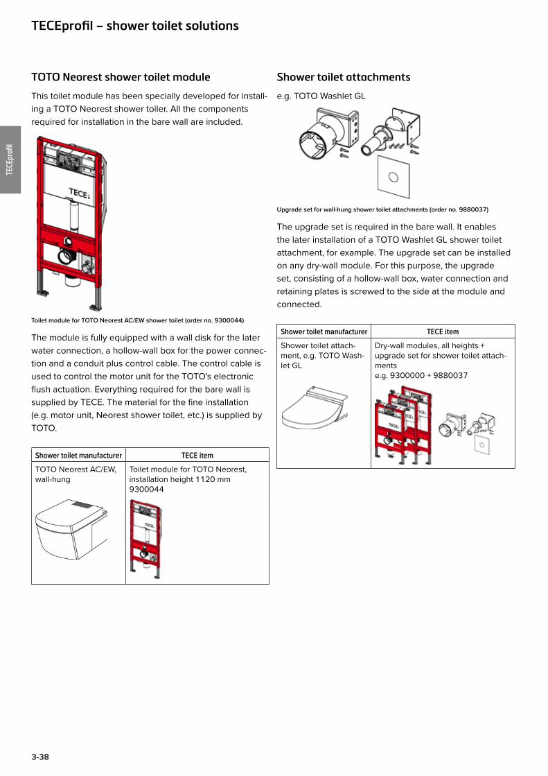
TOTO Neorest shower toilet module
This toilet module has been specially developed for install-ing a TOTO Neorest shower toiler. All the components required for installation in the bare wall are included.
Toilet module for TOTO Neorest AC/EW shower toilet (order no. 9300044)
The module is fully equipped with a wall disk for the later water connection, a hollow-wall box for the power connec-tion and a conduit plus control cable. The control cable is used to control the motor unit for the TOTO's electronic flush actuation. Everything required for the bare wall is supplied by TECE. The material for the fine installation (e.g. motor unit, Neorest shower toilet, etc.) is supplied by TOTO.
Shower toilet manufacturer TECE item
TOTO Neorest AC/EW, wall-hung
Toilet module for TOTO Neorest, installation height 1120 mm9300044
TECEprofil – shower toilet solutions
Shower toilet attachments
e.g. TOTO Washlet GL
Upgrade set for wall-hung shower toilet attachments (order no. 9880037)
The upgrade set is required in the bare wall. It enables the later installation of a TOTO Washlet GL shower toilet attachment, for example. The upgrade set can be installed on any dry-wall module. For this purpose, the upgrade set, consisting of a hollow-wall box, water connection and retaining plates is screwed to the side at the module and connected.
Shower toilet manufacturer TECE item
Shower toilet attach-ment, e.g. TOTO Wash-let GL
Dry-wall modules, all heights + upgrade set for shower toilet attach-mentse.g. 9300000 + 9880037

3-39
TECEprofi
l
TECEprofil toilet module for baby/children's standing toiletThis toilet module has been specially developed for using a floor-standing baby/children's standing toilet. Baby/children's standing toilets have a clearly lower seat height compared to normal toilet ceramics, and different connec-tion dimensions. The actuation height is also lowered in a way which is appropriate for children.
Both types of ceramics can be connected with the special baby/children toilet module. The flush pipe for connecting a baby toilet is pre-set in the as-delivered state. To achieve the slightly higher connection dimensions of a children's toilet, either the flush pipe can be shortened, or the cistern can be positioned slightly higher. By boring a drill hole in the lower brace, an optional drain bend can be attached if necessary via a pipe clip.
When using a baby toilet, the standard flush volume of 6/3 litres can be changed to 4.5/3 litres at any time.The universal module technology enables the toilet module to be installed in a TECEprofil wall, in metal or wooden stud walls or as an individual module. The toilet module is only suitable for baby/children's standing toilets. It is not possible to mount wall-hung toilet ceramics.
OKFF
0 -200
500
1120
905
260-
300
140-
170
min. 160150 90
Toilet module for baby/children's standing toilet (order no. 9300088)
TECEprofil – toilet module for baby/children's standing toilet
3-40
TECEprofi
l
Barrier-free construction with TECEprofil
Planning guidelines
• DIN 18 040 – Part 1 Planning fundamentals “Barrier-free building” in public-access buildings and workplaces.
• DIN 18 040 – Part 2 “Barrier-free building” (describes the requirements for sanitary rooms for wheelchair users in dwellings, etc.)
Barrier-free toilet system according to DIN 18 040 – part 1 in public buildings:
DIN 18 040 part 1 is the authoritative version for the cre-ation of a public barrier-free toilet system. Because of the highest assumed disability of a person in the public area, the requirements are considerably higher than those for private areas.
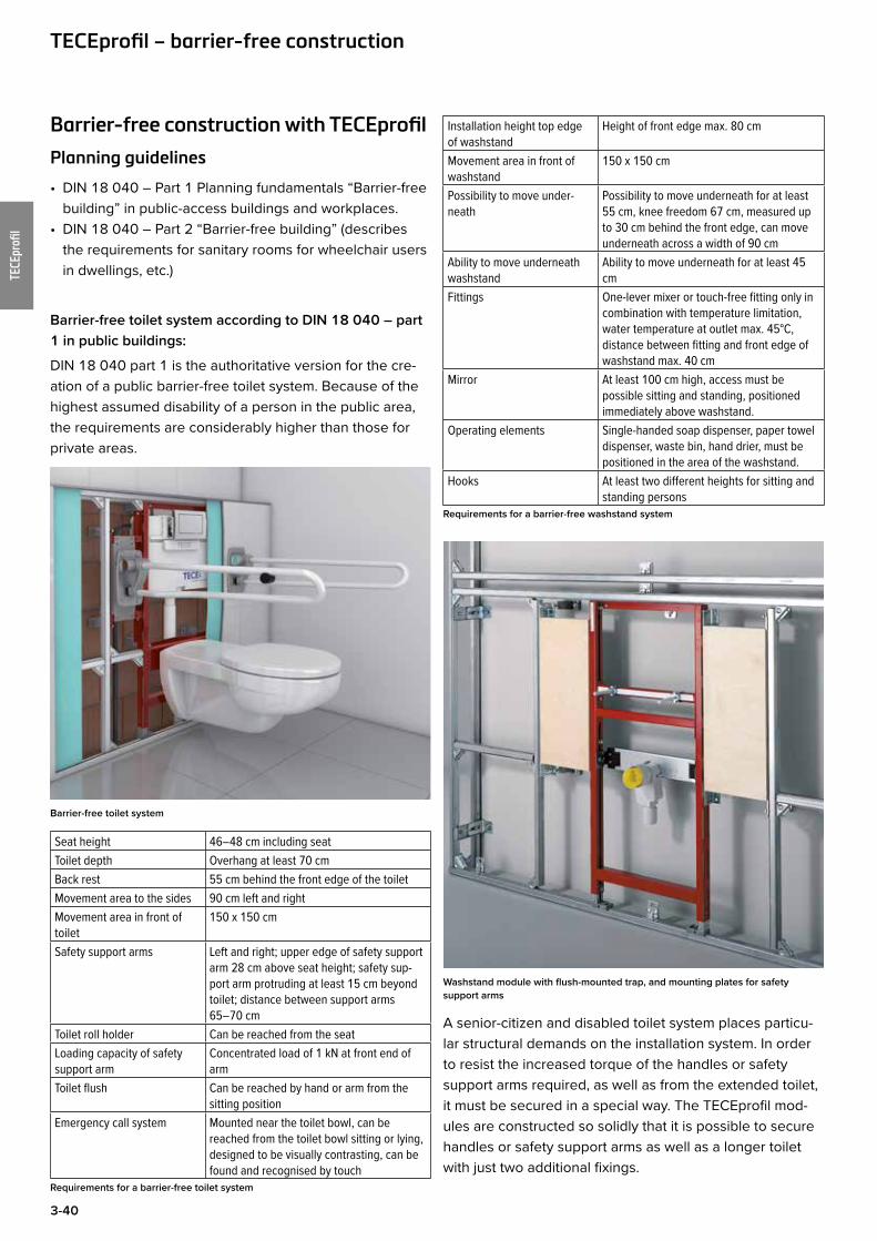
Barrier-free toilet system
Seat height 46–48 cm including seatToilet depth Overhang at least 70 cmBack rest 55 cm behind the front edge of the toiletMovement area to the sides 90 cm left and rightMovement area in front of toilet
150 x 150 cm
Safety support arms Left and right; upper edge of safety support arm 28 cm above seat height; safety sup-port arm protruding at least 15 cm beyond toilet; distance between support arms 65–70 cm
Toilet roll holder Can be reached from the seatLoading capacity of safety support arm
Concentrated load of 1 kN at front end of arm
Toilet flush Can be reached by hand or arm from the sitting position
Emergency call system Mounted near the toilet bowl, can be reached from the toilet bowl sitting or lying, designed to be visually contrasting, can be found and recognised by touch
Requirements for a barrier-free toilet system
Installation height top edge of washstand
Height of front edge max. 80 cm
Movement area in front of washstand
150 x 150 cm
Possibility to move under-neath
Possibility to move underneath for at least 55 cm, knee freedom 67 cm, measured up to 30 cm behind the front edge, can move underneath across a width of 90 cm
Ability to move underneath washstand
Ability to move underneath for at least 45 cm
Fittings One-lever mixer or touch-free fitting only in combination with temperature limitation, water temperature at outlet max. 45°C, distance between fitting and front edge of washstand max. 40 cm
Mirror At least 100 cm high, access must be possible sitting and standing, positioned immediately above washstand.
Operating elements Single-handed soap dispenser, paper towel dispenser, waste bin, hand drier, must be positioned in the area of the washstand.
Hooks At least two different heights for sitting and standing persons
Requirements for a barrier-free washstand system
Washstand module with flush-mounted trap, and mounting plates for safety support arms
A senior-citizen and disabled toilet system places particu-lar structural demands on the installation system. In order to resist the increased torque of the handles or safety support arms required, as well as from the extended toilet, it must be secured in a special way. The TECEprofil mod-ules are constructed so solidly that it is possible to secure handles or safety support arms as well as a longer toilet with just two additional fixings.
TECEprofil – barrier-free construction
3-41
TECEprofi
l
Barrier-free toilet system in a TECEprofil wall
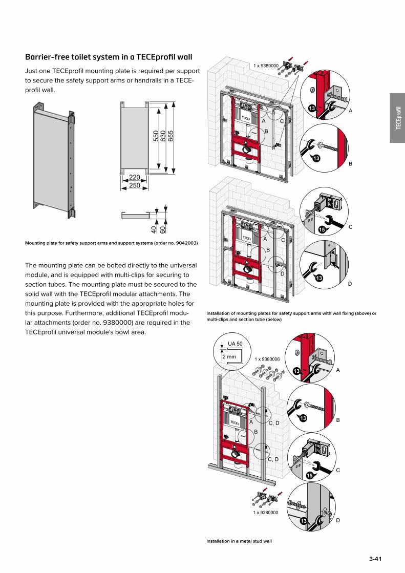
Just one TECEprofil mounting plate is required per support to secure the safety support arms or handrails in a TECE-profil wall.
Mounting plate for safety support arms and support systems (order no. 9042003)
The mounting plate can be bolted directly to the universal module, and is equipped with multi-clips for securing to section tubes. The mounting plate must be secured to the solid wall with the TECEprofil modular attachments. The mounting plate is provided with the appropriate holes for this purpose. Furthermore, additional TECEprofil modu-lar attachments (order no. 9380000) are required in the TECEprofil universal module's bowl area.
A
B
C
D
1 x 9380000
13
13
13
A
B
C
D
B
CA
Installation of mounting plates for safety support arms with wall fixing (above) or multi-clips and section tube (below)
1 x 9380006
1 x 9380000
13
13
A
B
C
A
BC, D
C, D
13 D
UA 50
2 mm
Installation in a metal stud wall
3-42
TECEprofi
l
Barrier-free toilet system in an individual mod-ular construction
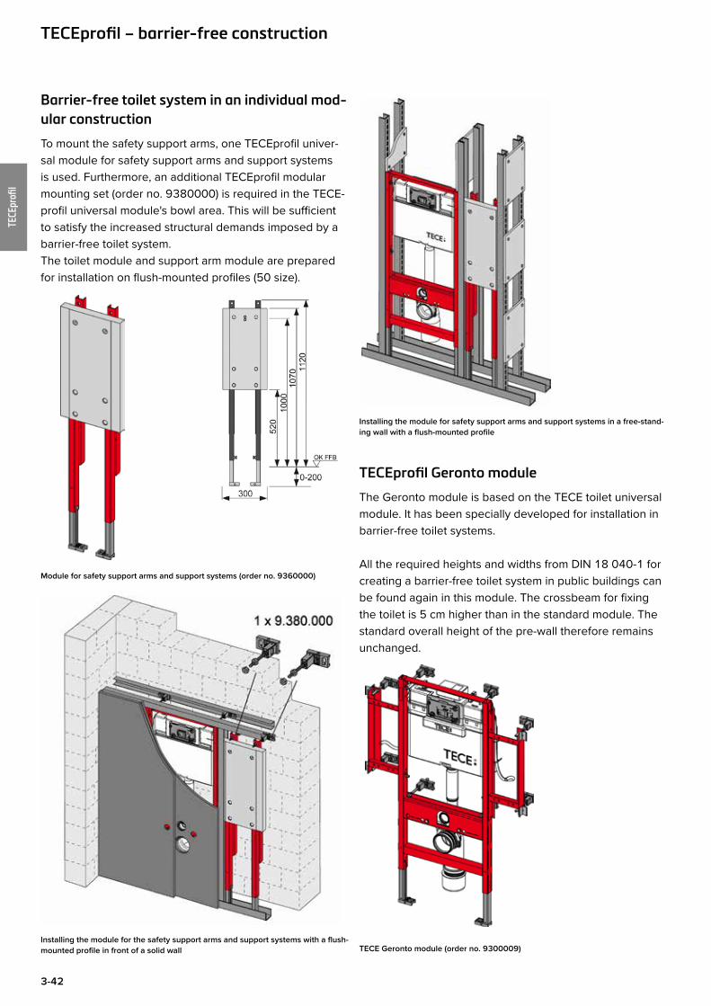
To mount the safety support arms, one TECEprofil univer-sal module for safety support arms and support systems is used. Furthermore, an additional TECEprofil modular mounting set (order no. 9380000) is required in the TECE-profil universal module's bowl area. This will be sufficient to satisfy the increased structural demands imposed by a barrier-free toilet system.The toilet module and support arm module are prepared for installation on flush-mounted profiles (50 size).
Module for safety support arms and support systems (order no. 9360000)
Installing the module for the safety support arms and support systems with a flush-mounted profile in front of a solid wall
Installing the module for safety support arms and support systems in a free-stand-ing wall with a flush-mounted profile
TECEprofil Geronto module
The Geronto module is based on the TECE toilet universal module. It has been specially developed for installation in barrier-free toilet systems.
All the required heights and widths from DIN 18 040-1 for creating a barrier-free toilet system in public buildings can be found again in this module. The crossbeam for fixing the toilet is 5 cm higher than in the standard module. The standard overall height of the pre-wall therefore remains unchanged.
TECE Geronto module (order no. 9300009)
TECEprofil – barrier-free construction
3-43
TECEprofi
l
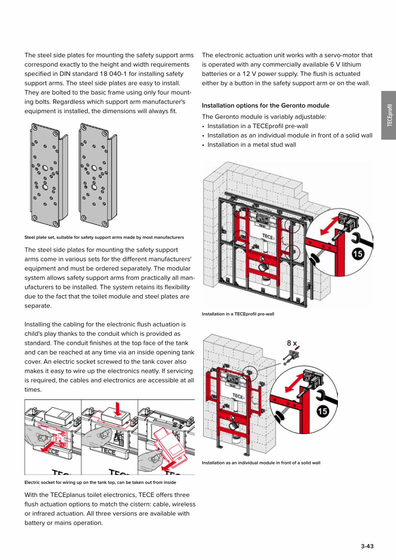
The steel side plates for mounting the safety support arms correspond exactly to the height and width requirements specified in DIN standard 18 040-1 for installing safety support arms. The steel side plates are easy to install. They are bolted to the basic frame using only four mount-ing bolts. Regardless which support arm manufacturer's equipment is installed, the dimensions will always fit.
Steel plate set, suitable for safety support arms made by most manufacturers
The steel side plates for mounting the safety support arms come in various sets for the different manufacturers' equipment and must be ordered separately. The modular system allows safety support arms from practically all man-ufacturers to be installed. The system retains its flexibility due to the fact that the toilet module and steel plates are separate.
Installing the cabling for the electronic flush actuation is child's play thanks to the conduit which is provided as standard. The conduit finishes at the top face of the tank and can be reached at any time via an inside opening tank cover. An electric socket screwed to the tank cover also makes it easy to wire up the electronics neatly. If servicing is required, the cables and electronics are accessible at all times.
Electric socket for wiring up on the tank top, can be taken out from inside
With the TECEplanus toilet electronics, TECE offers three flush actuation options to match the cistern: cable, wireless or infrared actuation. All three versions are available with battery or mains operation.
The electronic actuation unit works with a servo-motor that is operated with any commercially available 6 V lithium batteries or a 12 V power supply. The flush is actuated either by a button in the safety support arm or on the wall.
Installation options for the Geronto module
The Geronto module is variably adjustable:• Installation in a TECEprofil pre-wall• Installation as an individual module in front of a solid wall• Installation in a metal stud wall
Installation in a TECEprofil pre-wall
Installation as an individual module in front of a solid wall
3-44
TECEprofi
l
Installation in a metal stud wall
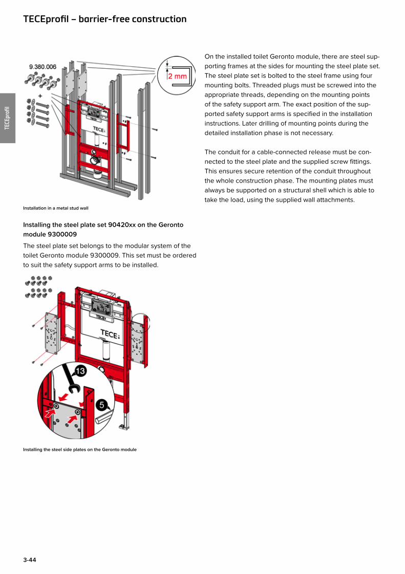
Installing the steel plate set 90420xx on the Geronto module 9300009
The steel plate set belongs to the modular system of the toilet Geronto module 9300009. This set must be ordered to suit the safety support arms to be installed.
Installing the steel side plates on the Geronto module
On the installed toilet Geronto module, there are steel sup-porting frames at the sides for mounting the steel plate set. The steel plate set is bolted to the steel frame using four mounting bolts. Threaded plugs must be screwed into the appropriate threads, depending on the mounting points of the safety support arm. The exact position of the sup-ported safety support arms is specified in the installation instructions. Later drilling of mounting points during the detailed installation phase is not necessary.
The conduit for a cable-connected release must be con-nected to the steel plate and the supplied screw fittings. This ensures secure retention of the conduit throughout the whole construction phase. The mounting plates must always be supported on a structural shell which is able to take the load, using the supplied wall attachments.
TECEprofil – barrier-free construction
3-45
TECEprofi
l
Sound insulationInsulation against installation noise is becoming increas-ingly important in sanitary and heating technology. Particu-lar attention has been given to sound insulation require-ments in the development of TECEprofil pre-wall elements. TECE products also enable the increased demands for structural sound insulation to be met.Not only the properties of the product, but planning tasks such as floor plan layout and the weights of walls are also very important for ensuring good sound insulation.
Relevant standards
Table 9 from DIN 4109-1:2016-07 describes the values for permissible sound pressure levels in rooms which require sound insulation. The values listed here are acknowledged as generally accepted engineering standards and always apply if no other agreement on sound insulation has been reached.
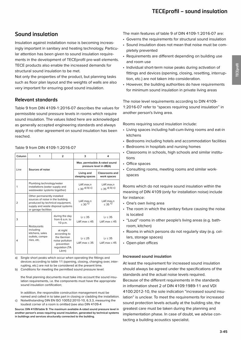
Table 9 from DIN 4109-1:2016-07
Column 1 2 3 4
Line Sources of noise
Max. permissible A-rated sound pressure level in dB(A)
Living and sleeping spaces
Classrooms and work spaces
1Plumbing technology/water installations (water supply and wastewater systems together)
LAF,max,n ≤ 30 a) b) c)
LAF,max,n ≤ 35 a) b) c)
2
Other permanently installed sources of noise in the building produced by technical equipment, supply and waste disposal systems or garage facilities
LAF,max,n ≤ 30 c)
LAF,max,n ≤ 35 c)
3
Restaurants including kitchens, sales outlets, compa-nies, etc.
during the day from 6 a.m. to
10 p.m.
Lr ≤ 35LAF,max ≤ 45
Lr ≤ 35LAF,max ≤ 45
4
at night according to the German
noise pollution prevention
regulation (TA Lärm)
Lr ≤ 25LAF,max ≤ 35
Lr ≤ 35LAF,max ≤ 45
a) Single short peaks which occur when operating the fittings and devices according to table 11 (opening, closing, changing over, inter-rupting, etc.) are not to be considered at the present time.
b) Conditions for meeting the permitted sound pressure level: the final planning documents must take into account the sound insu-lation requirements, i.e. the components must have the appropriate sound insulation certification; In addition, the responsible construction management must be named and called in to take part in closing or cladding the installation.
c) Notwithstanding DIN EN ISO 10052:2010-10, 6.3.3, measuring the loudest corner of a room is omitted (see also DIN 4109-4
Source: DIN 4109/table 9: The maximum available A-rated sound pressure level in another person's areas requiring sound insulation, generated by technical systems in buildings and services structurally connected to the building.
The main features of table 9 of DIN 4109-1:2016-07 are:• Governs the requirements for structural sound insulation• Sound insulation does not mean that noise must be com-
pletely prevented• Requirements are different depending on building use
and room use• Individual short-term noise peaks during activation of
fittings and devices (opening, closing, resetting, interrup-tion, etc.) are not taken into consideration.
• However, the building authorities do have requirements for minimum sound insulation in private living areas
The noise level requirements according to DIN 4109-1:2016-07 refer to “spaces requiring sound insulation” in another person's living area.
Rooms requiring sound insulation include:• Living spaces including hall-cum-living rooms and eat-in
kitchens • Bedrooms including hotels and accommodation facilities • Bedrooms in hospitals and nursing homes• Classrooms in schools, high schools and similar institu-
tions • Office spaces• Consulting rooms, meeting rooms and similar work-
spaces
Rooms which do not require sound insulation within the meaning of DIN 4109 (only for installation noise) include for instance:• One's own living area• The room in which the sanitary fixture causing the noise
is located • “Loud” rooms in other people's living areas (e.g. bath-
room, kitchen)• Rooms in which persons do not regularly stay (e.g. cel-
lars, storage spaces) • Open-plan offices
Increased sound insulation
At least the requirement for increased sound insulation should always be agreed under the specifications of the standards and the actual noise levels required.Because of the different requirements in the standards in information sheet 2 of DIN 4109:1989-11 and VDI 4100:2012-10, the sole indication “increased sound insu-lation” is unclear. To meet the requirements for increased sound protection levels actually at the building site, the greatest care must be taken during the planning and implementation phase. In case of doubt, we advise con-tacting a building acoustics specialist.
TECEprofil – sound insulation

3-46
TECEprofi
l
Overview of acoustic standards (sources of noise: plumbing technology, water installations)
Acoustic standard Protected areas
Max. permitted installation noise level
StandardIncreased sound insulation1)
Sound insulation level I
Sound insulation level II
Sound insulation level III
DIN 4109complies with the generally accepted engineering standard (recommendation: generally agreed under a works and services contract)
space requiring sound insulation, lying diago-nally below in another person's living area
LAF,max,n ≤ 30 dB(A)
- - -
neighbouring space requiring sound insulation in one's own area
no require-ment
- - -
Supplement 2 to DIN 41091)
(contract for works and services required)
space requiring sound insulation, lying diago-nally below in another person's living area
-LAF,max,n ≤ 252) dB(A)
- -
neighbouring space requiring sound insulation in one's own area
-no require-
ment- -
VDI 41001)
(contract for works and services required)
space requiring sound insulation, lying diago-nally below in another person's living area
-LAF,max,nT ≤
30 dB(A)LAF,max,nT ≤
27 dB(A)LAF,max,nT ≤
24 dB(A)
neighbouring space requiring sound insulation in one's own area
-LAF,max,nT ≤
303) dB(A)LAF,max,nT ≤
253) dB(A)LAF,max,nT ≤
223) dB(A)
1) If increased sound insulation is required, the standard and the exact numeric value of the increased sound insulation must be explicitly agreed in the works and services contract.
2) Sound pressure level values of 5 dB(A) or more under the values specified in DIN 4109/11.89, table 4 can be regarded as an effective reduction. In this case, addi-tional measures for airborne and impact sound insulation are required.
3) Caution: According to VDI guideline 4100, increased sound insulation in one's own area is automatically understood as agreed in a works and services contract.
Sound insulation of crossbeam from module frame
Should you have any questions about structural sound insulation, including in relation to a project, we would be pleased to help. Expert reports and statements available on request.
TECEprofil – sound insulation
TECEprofil system sound-proofing measures
Particular attention has been paid to sound insulation requirements in the development of TECEprofil. For exam-ple, special decoupling components specifically reduce the transfer of acoustic waves. Different structures have been tested in collaboration with various well-known insti-tutes. The acoustic properties according to DIN 4109 have been confirmed by expert assessments.
Sound insulation of cistern from module frame
3-47
TECEprofi
l
TECEprofil sound insulation verification
Installation sound level LAF,max,n (Lin)
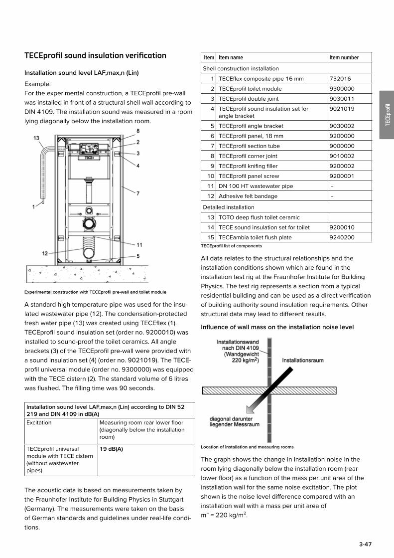
Example:For the experimental construction, a TECEprofil pre-wall was installed in front of a structural shell wall according to DIN 4109. The installation sound was measured in a room lying diagonally below the installation room.
Experimental construction with TECEprofil pre-wall and toilet module
A standard high temperature pipe was used for the insu-lated wastewater pipe (12). The condensation-protected fresh water pipe (13) was created using TECEflex (1). TECEprofil sound insulation set (order no. 9200010) was installed to sound-proof the toilet ceramics. All angle brackets (3) of the TECEprofil pre-wall were provided with a sound insulation set (4) (order no. 9021019). The TECE-profil universal module (order no. 9300000) was equipped with the TECE cistern (2). The standard volume of 6 litres was flushed. The filling time was 90 seconds.
Installation sound level LAF,max,n (Lin) according to DIN 52 219 and DIN 4109 in dB(A)Excitation Measuring room rear lower floor
(diagonally below the installation room)
TECEprofil universal module with TECE cistern (without wastewater pipes)
19 dB(A)
The acoustic data is based on measurements taken by the Fraunhofer Institute for Building Physics in Stuttgart (Germany). The measurements were taken on the basis of German standards and guidelines under real-life condi-tions.
Item Item name Item number
Shell construction installation
1 TECEflex composite pipe 16 mm 732016
2 TECEprofil toilet module 9300000
3 TECEprofil double joint 9030011
4 TECEprofil sound insulation set for angle bracket
9021019
5 TECEprofil angle bracket 9030002
6 TECEprofil panel, 18 mm 9200000
7 TECEprofil section tube 9000000
8 TECEprofil corner joint 9010002
9 TECEprofil knifing filler 9200002
10 TECEprofil panel screw 9200001
11 DN 100 HT wastewater pipe -
12 Adhesive felt bandage -
Detailed installation
13 TOTO deep flush toilet ceramic
14 TECE sound insulation set for toilet 9200010
15 TECEambia toilet flush plate 9240200TECEprofil list of components
All data relates to the structural relationships and the installation conditions shown which are found in the installation test rig at the Fraunhofer Institute for Building Physics. The test rig represents a section from a typical residential building and can be used as a direct verification of building authority sound insulation requirements. Other structural data may lead to different results.
Influence of wall mass on the installation noise level
Location of installation and measuring rooms
The graph shows the change in installation noise in the room lying diagonally below the installation room (rear lower floor) as a function of the mass per unit area of the installation wall for the same noise excitation. The plot shown is the noise level difference compared with an installation wall with a mass per unit area of m” = 220 kg/m².

3-48
TECEprofi
l
Change in the installation noise level – calculated results (calculated by the Fraunhofer Institute for Building Physics, Stuttgart)
The calculated results shown refer to the relationships in the installation test rig at the Fraunhofer Institute for Build-ing Physics and cannot be directly applied to other build-ing situations. To simplify the calculations, it was assumed that the thickness, inner damping and module of elasticity of the installation wall do not change.
Rated sound reduction index R’w
According to DIN 4109, general requirements for sound insulation apply to dividing walls in other people's living and working areas. Here, this concerns the value known as “rated sound reduction index” R’w. The rated sound reduc-tion index R’w characterises the airborne sound reduction by components.
Extract from DIN 4109-1:2016-07
Requirements in multi-storey dwellings, offices and mixed-use buildings
The requirements for airborne sound reduction R'w and impact noise insulation L'n,w between other people's
TECEprofil – sound insulation
functional units, e.g. between other people's flats and/or between flats and other people's work areas (offices, doctor's practices and businesses) are listed in table 2.
Extract from table 2:Line Components Requirements Comments
R'wdB
L'n,wdB
13
Walls
Walls dividing flats and walls between other people's work areas
≥ 53 – Walls dividing flats are components which sepa-rate flats from each other or from other people's
work areas.14 Staircase walls and walls adjacent to hallways ≥ 53 – For walls with doors, the requirement R'w (wall)
= R'w (door) + 15 dB applies where, R'w (door) means the required sound proofing for the door according to line 18 or line 19. wall widths≤ 30 cm are not taken into account in the process.
15 Walls adjacent to passageways and commu-nal garages including driveways
≥ 55 –
16 Walls of games rooms or common rooms ≥ 55 –17 Shaft walls of lift systems adjacent to residen-
tial rooms≥ 57 –
3-49
TECEprofi
l
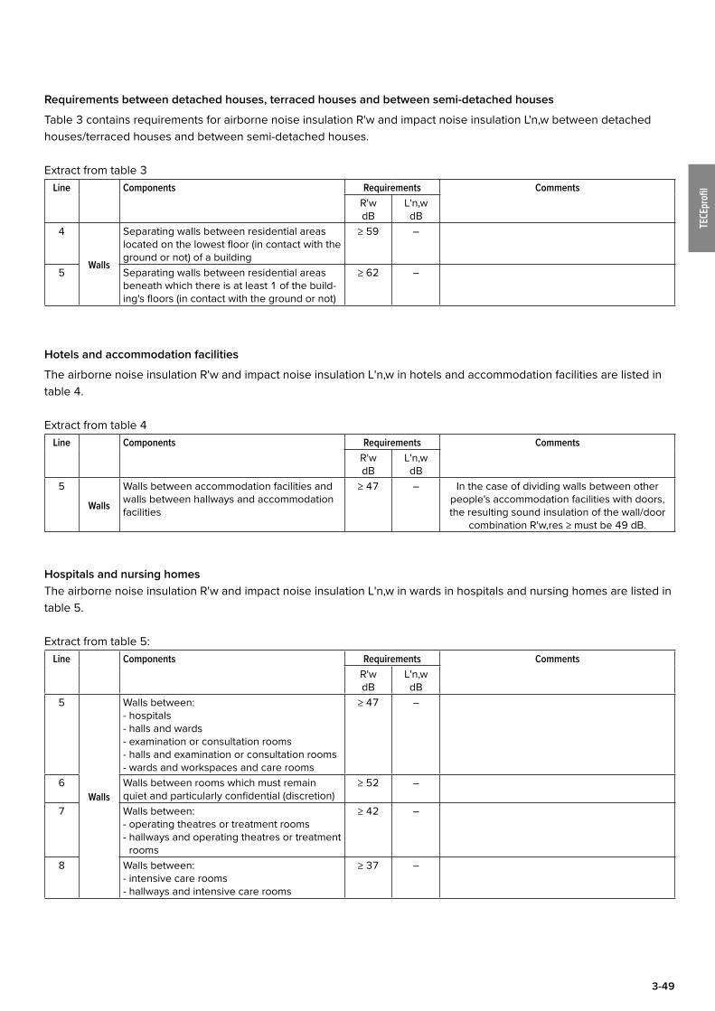
Requirements between detached houses, terraced houses and between semi-detached houses
Table 3 contains requirements for airborne noise insulation R'w and impact noise insulation L'n,w between detached houses/terraced houses and between semi-detached houses.
Extract from table 3Line Components Requirements Comments
R'wdB
L'n,wdB
4
Walls
Separating walls between residential areas located on the lowest floor (in contact with the ground or not) of a building
≥ 59 –
5 Separating walls between residential areas beneath which there is at least 1 of the build-ing's floors (in contact with the ground or not)
≥ 62 –
Hotels and accommodation facilities
The airborne noise insulation R'w and impact noise insulation L'n,w in hotels and accommodation facilities are listed in table 4.
Extract from table 4Line Components Requirements Comments
R'wdB
L'n,wdB
5
Walls
Walls between accommodation facilities and walls between hallways and accommodation facilities
≥ 47 – In the case of dividing walls between other people's accommodation facilities with doors, the resulting sound insulation of the wall/door
combination R'w,res ≥ must be 49 dB.
Hospitals and nursing homesThe airborne noise insulation R'w and impact noise insulation L'n,w in wards in hospitals and nursing homes are listed in table 5.
Extract from table 5:Line Components Requirements Comments
R'wdB
L'n,wdB
5
Walls
Walls between:- hospitals- halls and wards- examination or consultation rooms- halls and examination or consultation rooms- wards and workspaces and care rooms
≥ 47 –
6 Walls between rooms which must remain quiet and particularly confidential (discretion)
≥ 52 –
7 Walls between:- operating theatres or treatment rooms- hallways and operating theatres or treatment
rooms
≥ 42 –
8 Walls between:- intensive care rooms- hallways and intensive care rooms
≥ 37 –

3-50
TECEprofi
l
Schools and similar institutions (e.g. training centres)The airborne noise insulation R'w and impact noise insulation L'n,w between rooms in schools and similar facilities are listed in table 6.
Extract from table 6:Line Components Requirements Comments
R'wdB
L'n,wdB
4
Walls
Walls between classrooms or between similar rooms and hallways
≥ 47 –Similar rooms also include rooms which must
remain quiet e.g. dormitories.5 Walls between classrooms or similar rooms and stairwells
≥ 52 –
6 Walls between classrooms or similar rooms and “loud” rooms (e.g. dining rooms, cafete-rias, music rooms, games rooms, technical centres)
≥ 55 –
7 Walls between classrooms or similar rooms and sports halls and work areas, for instance
≥ 60 –
Extract from supplement 2 to DIN 4109
One's own living or work area
Sound insulation of dividing walls within one's own living or work space, rated sound reduction index R'w between 2 rooms; suggestions according to DIN 4109 supplement 2 for normal and increased sound insulation:
Line Description Rated sound reduction index R'w according to DIN 4109 supplement 2
Normal requirements Increased requirements
4 Residential building- Walls without doors between “loud” and “quiet” rooms
with various uses≥ 40 dB ≥ 47 dB
5 Offices and administration rooms- Walls between rooms with usual office activities- Walls between these and hallways- Walls of rooms for concentrated intellectual activity
≥ 37 dB≥ 37 dB≥ 45 dB
≥ 42 dB≥ 42 dB≥ 52 dB
TECEprofil – sound insulation
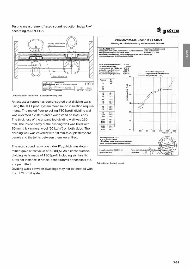
3-51
TECEprofi
l
Test rig measurement “rated sound reduction index R’w” according to DIN 4109
Construction of the tested TECEprofil dividing wall
An acoustics report has demonstrated that dividing walls using the TECEprofil system meet sound insulation require-ments. The tested floor-to-ceiling TECEprofil dividing wall was allocated a cistern and a washstand on both sides. The thickness of the unpanelled dividing wall was 250 mm. The inside cavity of the dividing wall was filled with 60 mm-thick mineral wool (50 kg/m³) on both sides. The dividing wall was covered with 18 mm-thick plasterboard panels and the joints between them were filled.
The rated sound reduction index R’W,Rwhich was deter-mined gave a test value of 52 dB(A). As a consequence, dividing walls made of TECEprofil including sanitary fix-tures, for instance in hotels, schoolrooms or hospitals etc. are permitted.Dividing walls between dwellings may not be created with the TECEprofil system.
Extract from the test report
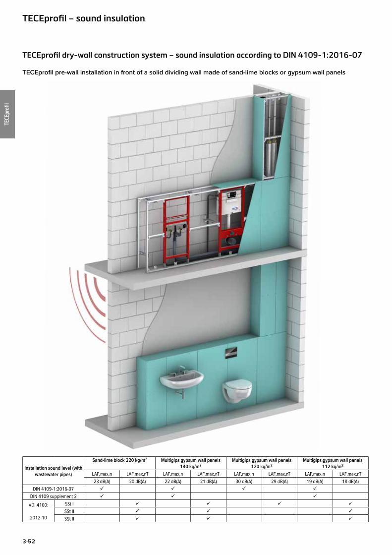
3-52
TECEprofi
l
TECEprofil dry-wall construction system – sound insulation according to DIN 4109-1:2016-07
TECEprofil pre-wall installation in front of a solid dividing wall made of sand-lime blocks or gypsum wall panels
Installation sound level (with wastewater pipes)
Sand-lime block 220 kg/m2 Multigips gypsum wall panels 140 kg/m2
Multigips gypsum wall panels 120 kg/m2
Multigips gypsum wall panels 112 kg/m2
LAF,max,n LAF,max,nT LAF,max,n LAF,max,nT LAF,max,n LAF,max,nT LAF,max,n LAF,max,nT23 dB(A) 20 dB(A) 22 dB(A) 21 dB(A) 30 dB(A) 29 dB(A) 19 dB(A) 18 dB(A)
DIN 4109-1:2016-07
DIN 4109 supplement 2
VDI 4100:
2012-10
SSt I
SSt II
SSt II
TECEprofil – sound insulation

3-53
TECEprofi
l
TECEprofil as a space-enclosing dividing wall
Sound reduction index
RW,R = 52 dB(A)
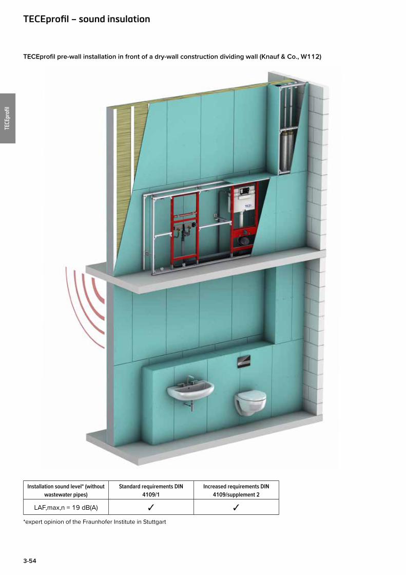
3-54
TECEprofi
l
TECEprofil pre-wall installation in front of a dry-wall construction dividing wall (Knauf & Co., W112)
Installation sound level* (without wastewater pipes)
Standard requirements DIN 4109/1
Increased requirements DIN 4109/supplement 2
LAF,max,n = 19 dB(A) ✓ ✓
*expert opinion of the Fraunhofer Institute in Stuttgart
TECEprofil – sound insulation
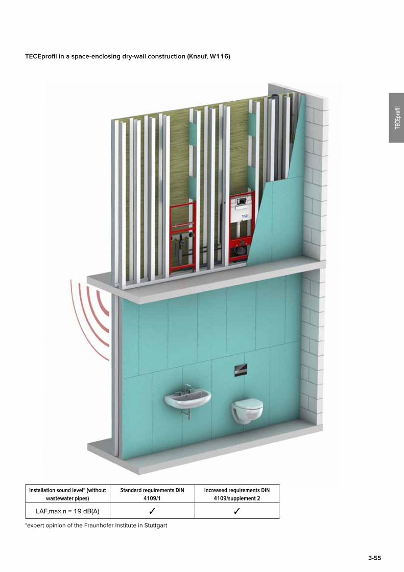
3-55
TECEprofi
l
TECEprofil in a space-enclosing dry-wall construction (Knauf, W116)
Installation sound level* (without wastewater pipes)
Standard requirements DIN 4109/1
Increased requirements DIN 4109/supplement 2
LAF,max,n = 19 dB(A) ✓ ✓
*expert opinion of the Fraunhofer Institute in Stuttgart
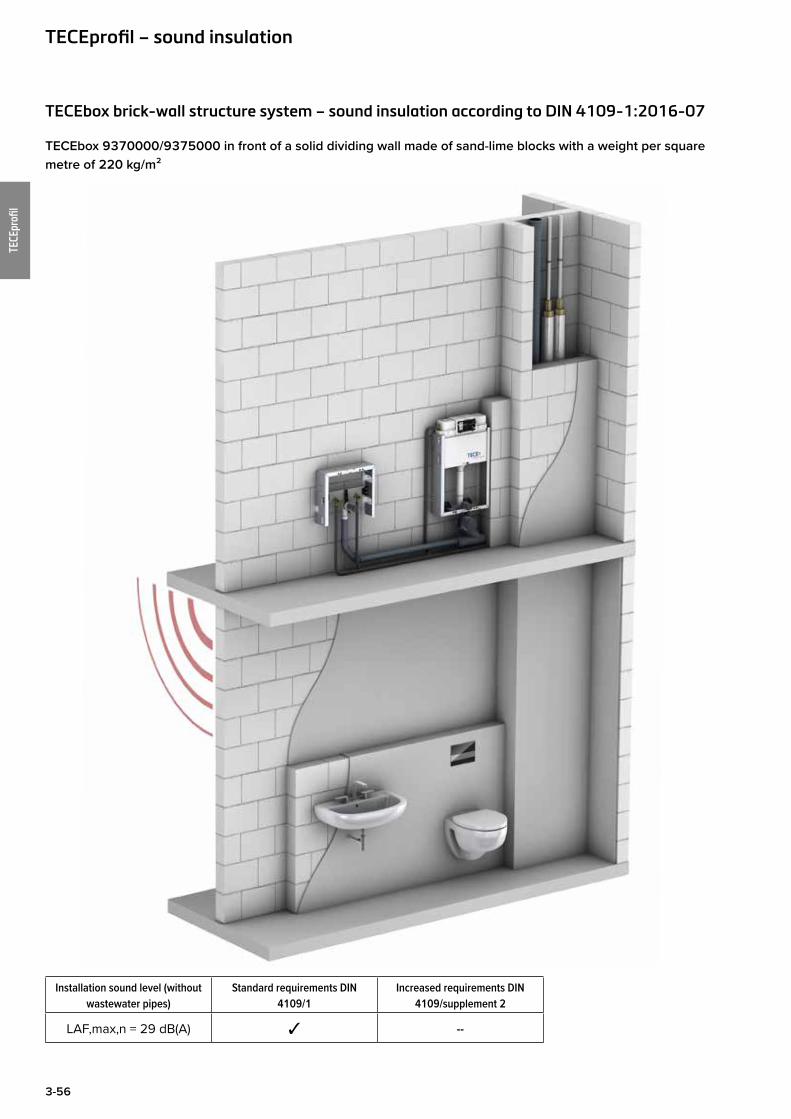
3-56
TECEprofi
l
TECEbox brick-wall structure system – sound insulation according to DIN 4109-1:2016-07
TECEbox 9370000/9375000 in front of a solid dividing wall made of sand-lime blocks with a weight per square metre of 220 kg/m²
Installation sound level (without wastewater pipes)
Standard requirements DIN 4109/1
Increased requirements DIN 4109/supplement 2
LAF,max,n = 29 dB(A) ✓ --
TECEprofil – sound insulation

3-57
TECEprofi
l
TECEbox plus 9371000 including building area cover 9200012
Installation sound level (without wastewater pipes)
Standard requirements DIN 4109/1
Increased requirements DIN 4109/supplement 2
LAF,max,n = 28 dB(A)* ✓ --
*The cavity below the cistern and the cavity in the drain area must be filled with mineral wool for this purpose.
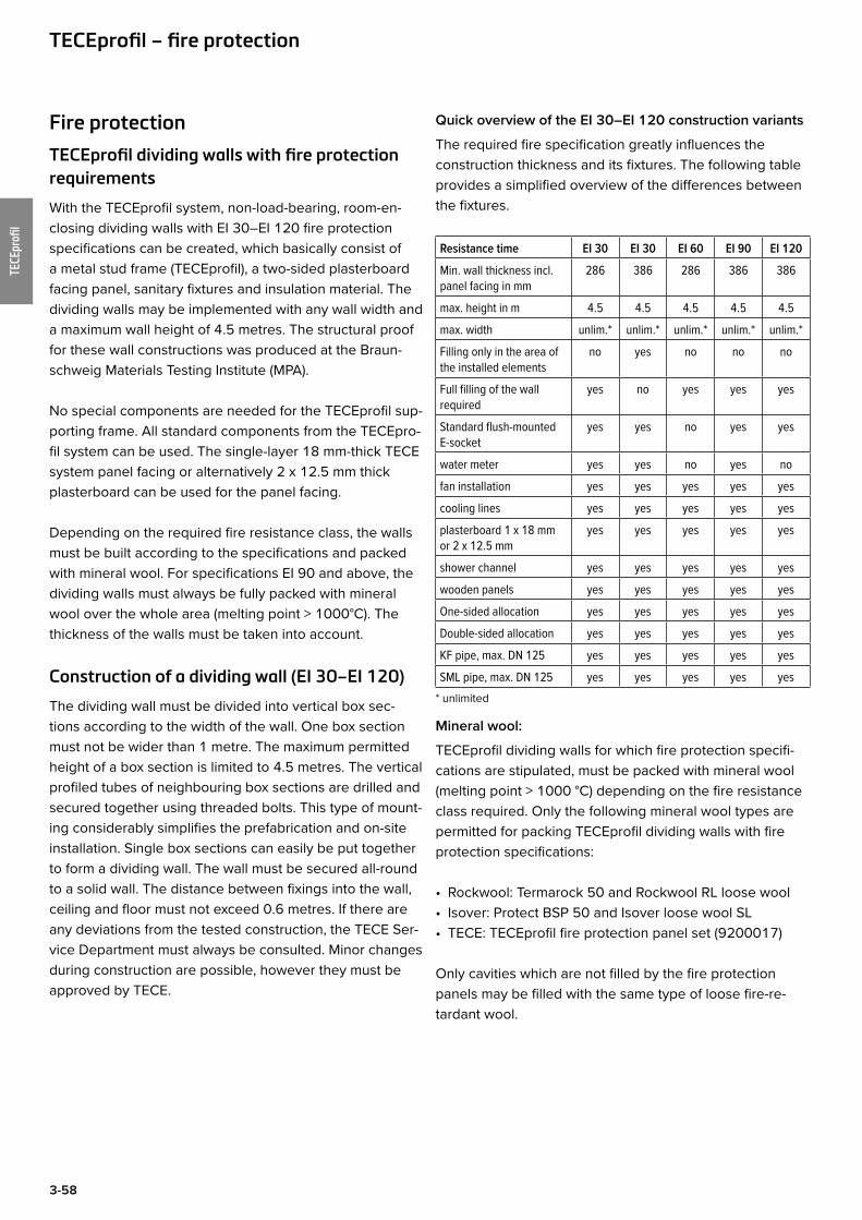
3-58
TECEprofi
l
Fire protection
TECEprofil dividing walls with fire protection requirements
With the TECEprofil system, non-load-bearing, room-en-closing dividing walls with EI 30–EI 120 fire protection specifications can be created, which basically consist of a metal stud frame (TECEprofil), a two-sided plasterboard facing panel, sanitary fixtures and insulation material. The dividing walls may be implemented with any wall width and a maximum wall height of 4.5 metres. The structural proof for these wall constructions was produced at the Braun-schweig Materials Testing Institute (MPA).
No special components are needed for the TECEprofil sup-porting frame. All standard components from the TECEpro-fil system can be used. The single-layer 18 mm-thick TECE system panel facing or alternatively 2 x 12.5 mm thick plasterboard can be used for the panel facing.
Depending on the required fire resistance class, the walls must be built according to the specifications and packed with mineral wool. For specifications EI 90 and above, the dividing walls must always be fully packed with mineral wool over the whole area (melting point > 1000°C). The thickness of the walls must be taken into account.
Construction of a dividing wall (EI 30–EI 120)
The dividing wall must be divided into vertical box sec-tions according to the width of the wall. One box section must not be wider than 1 metre. The maximum permitted height of a box section is limited to 4.5 metres. The vertical profiled tubes of neighbouring box sections are drilled and secured together using threaded bolts. This type of mount-ing considerably simplifies the prefabrication and on-site installation. Single box sections can easily be put together to form a dividing wall. The wall must be secured all-round to a solid wall. The distance between fixings into the wall, ceiling and floor must not exceed 0.6 metres. If there are any deviations from the tested construction, the TECE Ser-vice Department must always be consulted. Minor changes during construction are possible, however they must be approved by TECE.
TECEprofil – fire protection
Quick overview of the EI 30–EI 120 construction variants
The required fire specification greatly influences the construction thickness and its fixtures. The following table provides a simplified overview of the differences between the fixtures.
Resistance time EI 30 EI 30 EI 60 EI 90 EI 120
Min. wall thickness incl. panel facing in mm
286 386 286 386 386
max. height in m 4.5 4.5 4.5 4.5 4.5
max. width unlim.* unlim.* unlim.* unlim.* unlim.*
Filling only in the area of the installed elements
no yes no no no
Full filling of the wall required
yes no yes yes yes
Standard flush-mounted E-socket
yes yes no yes yes
water meter yes yes no yes no
fan installation yes yes yes yes yes
cooling lines yes yes yes yes yes
plasterboard 1 x 18 mm or 2 x 12.5 mm
yes yes yes yes yes
shower channel yes yes yes yes yes
wooden panels yes yes yes yes yes
One-sided allocation yes yes yes yes yes
Double-sided allocation yes yes yes yes yes
KF pipe, max. DN 125 yes yes yes yes yes
SML pipe, max. DN 125 yes yes yes yes yes* unlimited
Mineral wool:
TECEprofil dividing walls for which fire protection specifi-cations are stipulated, must be packed with mineral wool (melting point > 1000 °C) depending on the fire resistance class required. Only the following mineral wool types are permitted for packing TECEprofil dividing walls with fire protection specifications:
• Rockwool: Termarock 50 and Rockwool RL loose wool• Isover: Protect BSP 50 and Isover loose wool SL• TECE: TECEprofil fire protection panel set (9200017)
Only cavities which are not filled by the fire protection panels may be filled with the same type of loose fire-re-tardant wool.
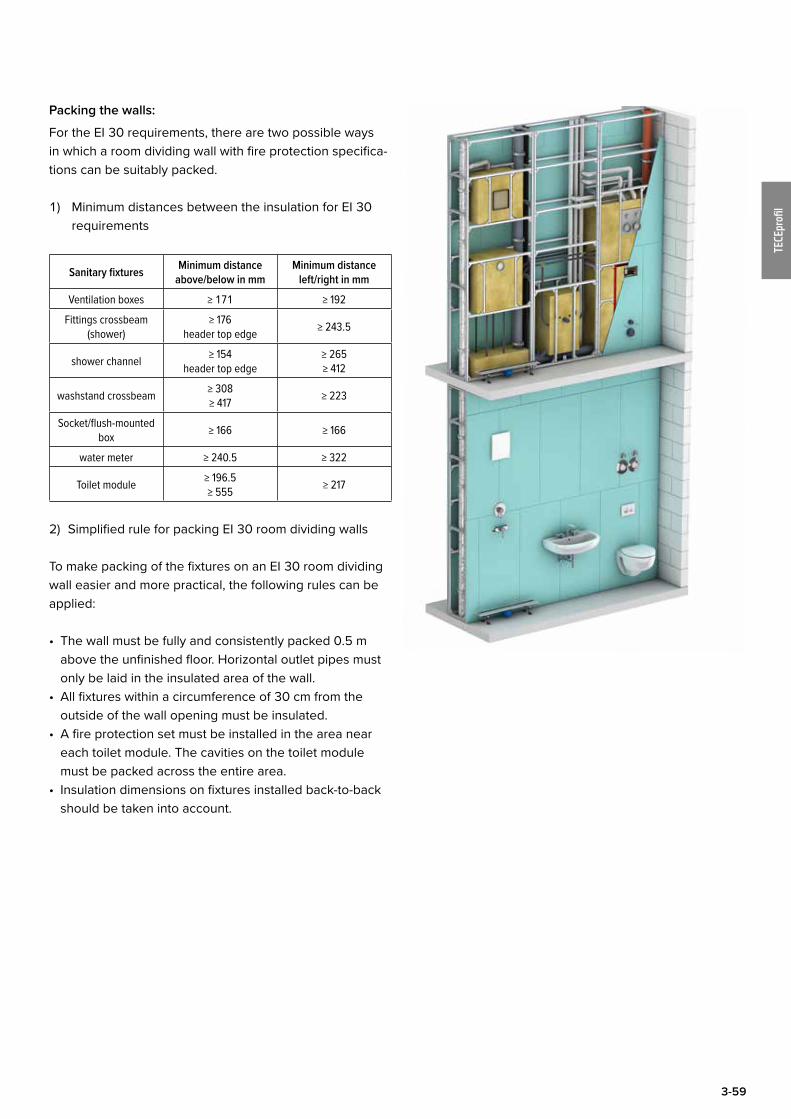
3-59
TECEprofi
l
Packing the walls:
For the EI 30 requirements, there are two possible ways in which a room dividing wall with fire protection specifica-tions can be suitably packed.
1) Minimum distances between the insulation for EI 30 requirements
Sanitary fixtures Minimum distance above/below in mm
Minimum distance left/right in mm
Ventilation boxes ≥ 171 ≥ 192
Fittings crossbeam (shower)
≥ 176 header top edge ≥ 243.5
shower channel ≥ 154 header top edge
≥ 265 ≥ 412
washstand crossbeam ≥ 308 ≥ 417 ≥ 223
Socket/flush-mounted box ≥ 166 ≥ 166
water meter ≥ 240.5 ≥ 322
Toilet module ≥ 196.5 ≥ 555 ≥ 217
2) Simplified rule for packing EI 30 room dividing walls
To make packing of the fixtures on an EI 30 room dividing wall easier and more practical, the following rules can be applied:
• The wall must be fully and consistently packed 0.5 m above the unfinished floor. Horizontal outlet pipes must only be laid in the insulated area of the wall.
• All fixtures within a circumference of 30 cm from the outside of the wall opening must be insulated.
• A fire protection set must be installed in the area near each toilet module. The cavities on the toilet module must be packed across the entire area.
• Insulation dimensions on fixtures installed back-to-back should be taken into account.
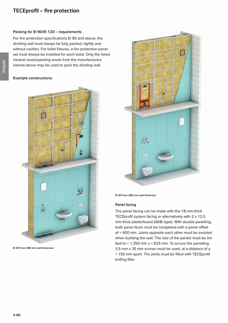
3-60
TECEprofi
l
Packing for EI 90/EI 120 – requirements
For fire protection specifications EI 90 and above, the dividing wall must always be fully packed, tightly and without cavities. For toilet fixtures, a fire protection panel set must always be installed for each toilet. Only the listed mineral wools/packing wools from the manufacturers named above may be used to pack the dividing wall.
Example constructions:
EI 90 from 386 mm wall thickness
EI 90 from 286 mm wall thickness
Panel facing
The panel facing can be made with the 18 mm-thick TECEprofil system facing or alternatively with 2 x 12.5 mm-thick plasterboard (GKBi type). With double panelling, both panel faces must be completed with a panel offset of < 400 mm. Joints opposite each other must be avoided when building the wall. The size of the panels must be lim-ited to < 1,350 mm x < 625 mm. To secure the panelling, 3.5 mm x 35 mm screws must be used, at a distance of a < 150 mm apart. The joints must be filled with TECEprofil knifing filler.
TECEprofil – fire protection
3-61
TECEprofi
l
Fixtures
Taking into consideration each technical regulation (e.g. building regulations) and fire resistance periods, the fol-lowing fixtures may be used:
a) fan housing with F 90 fire protection housing and max-imum outside dimensions of 249 x 249 mm, distance between backs a ≥ 160 (wall d ≥ 386 mm) or a ≥ 46 mm (wall d ≥ 286 mm)
b) installation boxes for water fittings (e.g. Hans Grohe i-box)
c) shower channels, e.g. TECEdrainlined) connection units and modules e.g. for washstand,
bidet, urinal etc.e) Toilet module with TECE cistern, with back-to-back
installation, minimum distance apart a ≥ 56 mmf) mounting plates made of building plywood, e.g. for
mounting safety support arms, max. dimensions (w x h x d) = 215 mm x 550 mm x 40 mm
g) insulated water meter units with shut-offs, max. dimen-sions w x h = 290 mm x 290 mm, depth d = 70 mm, distance apart for back-to-back installation of the hous-ing a≥ 210 mm (wall d ≥ 386 mm)
h) flush-mounted electric socket without fire protection approval
Pipework
In TECEprofil dividing walls with fire protection specifi-cations, the most varied pipe materials may be used. No special manufacturers are specified here. The following pipe materials have been tested and authorised:
Ventilation pipes:• DN 125 folded spiral seam pipe ≤ with DN 80 steel
braided pipes
Foul water and rain water pipes: • Sound insulated plastic pipe up to DN 125• SML cast iron pipe up to DN 125
Fresh water, heating and cooling pipes:• Plastic pipes up to 63 mm (outside diameter)• Multi-layer composite pipes up to 63 mm (outside diam-
eter)• Metal pipes made of copper or stainless steel up to 63
mm (outside diameter)
Pipes may be insulated with foam insulation (e.g. rub-ber-based), aluminium-clad mineral wool (e.g. Rockwool RS 800) or corrugated tubes.
Electric cables
Individual cables may pass through the classified space-enclosing wall structures, provided that the remain-ing hole cross-section is completely closed with plaster.
Implementation of bundled electric cables requires parti-tioning, the fire resistance class of which must be proven according to DIN 4102-9: 1990-05. Further evidence of suitability is necessary, e.g. within the scope of the issue of a general technical approval.
For the horizontal implementation of bundled electric cables, installation channels, cable ducts or ventilation lines, partitioning is required, the fire resistance class of which must be proven according to DIN 4102-11: 1985-12, DIN 4102-12: 1988-11 or DIN 4102-6: 1977-09. Further evidence of suitability is necessary, e.g. within the scope of the issue of a general technical approval on or a general appraisal certificate.
Electrical sockets
Depending on the application, standard wall-mounted electrical sockets may be used, combined with packing at the rear with mineral wool.
Only exception: EI 90 with a wall thickness of ≤ 386 mmIn this case, a flush-mounted electrical socket with EI 90 approval must be used.
Fan fixtures
Fan boxes may be arranged in the dividing walls directly opposite each other or offset. Care must be taken to ensure that for all the required fire classes, only fan boxes with a EI 90 approval may be used. The connection ducts to the fan and the riser ducts must always be made of steel.
If shut-off units providing protection against the trans-mission of fire are to be built into fan ducts with certain fire resistance classes, the suitability of these fixtures in combination with the wall construction must be proven according to DIN 4102-5: 1977-09, DIN 4102-6: 1977-09 or DIN 4102-13: 1990-05. Further evidence of suitability is necessary, e.g. within the scope of the issue of a general technical approval.

3-62
TECEprofi
l

All data contained in the Technical Guidelines has been compiled with the utmost care. The correctness of the data presented cannot be guaranteed, however. TECE assumes no liability for damages resulting from the use of this information. Text and images are protected by copyright law.
© Copyright 2018, TECE GmbH, Hollefeldstraße 57, 48282 Emsdetten, Germany