Embed Size (px)
Citation preview

Po-Hao Chen Duan Harrion
Denise Nguyen Keisuke Sasaki
Drosophila Melanogaster Anesthesia and Separation System
SPONSORED BY: Genesee Scientific
FACULTY MENTOR: Marti M. Sarigul-Klijn
FINAL REPORT
EME-185A/B
Marti M. Sarigul-Klijn
Michael LeVasseur
May 29, 2015
Table of Contents Abstract ........................................................................................................................................................ 3
Final Layout Drawings of Systems and Subsystems .................................................................................... 4
Fly Anesthesia Pad .................................................................................................................................... 5
Filtration and Disposal Systems ................................................................................................................ 6
Final Bill of Materials ................................................................................................................................... 7
Summary Report .......................................................................................................................................... 7
Flypad Summary ....................................................................................................................................... 7
Filter Summary .......................................................................................................................................... 8
Project Management Information ............................................................................................................... 9
Bibliography................................................................................................................................................ 10
Appendix ..................................................................................................................................................... 10
Design Analysis ........................................................................................................................................ 10
Flypad .................................................................................................................................................. 10
Vacuum Systems ................................................................................................................................. 11
User Manual ............................................................................................................................................ 12
Supplies ............................................................................................................................................... 12
Setup ................................................................................................................................................... 14
Instructions ......................................................................................................................................... 15
Maintenance and Repair ..................................................................................................................... 15
Replacement Parts .............................................................................................................................. 15
Solidworks Drawings and Assemblies ..................................................................................................... 16
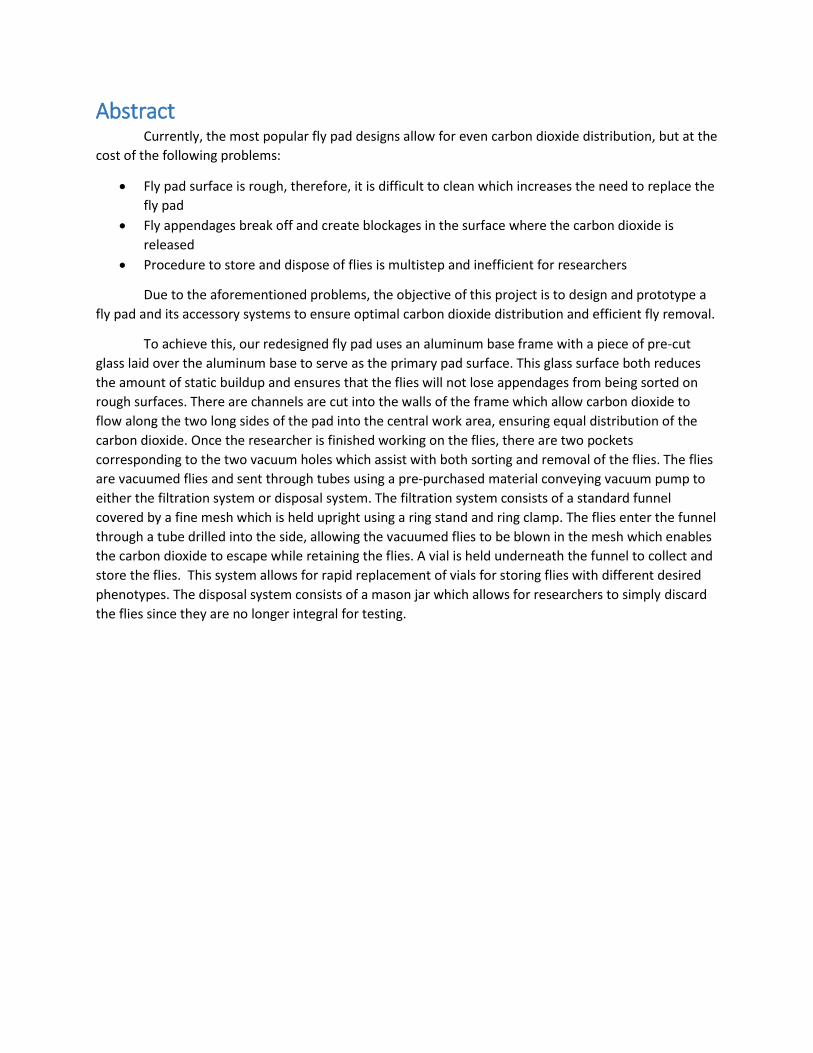
Abstract Currently, the most popular fly pad designs allow for even carbon dioxide distribution, but at the
cost of the following problems:
Fly pad surface is rough, therefore, it is difficult to clean which increases the need to replace the
fly pad
Fly appendages break off and create blockages in the surface where the carbon dioxide is
released
Procedure to store and dispose of flies is multistep and inefficient for researchers
Due to the aforementioned problems, the objective of this project is to design and prototype a
fly pad and its accessory systems to ensure optimal carbon dioxide distribution and efficient fly removal.
To achieve this, our redesigned fly pad uses an aluminum base frame with a piece of pre-cut
glass laid over the aluminum base to serve as the primary pad surface. This glass surface both reduces
the amount of static buildup and ensures that the flies will not lose appendages from being sorted on
rough surfaces. There are channels are cut into the walls of the frame which allow carbon dioxide to
flow along the two long sides of the pad into the central work area, ensuring equal distribution of the
carbon dioxide. Once the researcher is finished working on the flies, there are two pockets
corresponding to the two vacuum holes which assist with both sorting and removal of the flies. The flies
are vacuumed flies and sent through tubes using a pre-purchased material conveying vacuum pump to
either the filtration system or disposal system. The filtration system consists of a standard funnel
covered by a fine mesh which is held upright using a ring stand and ring clamp. The flies enter the funnel
through a tube drilled into the side, allowing the vacuumed flies to be blown in the mesh which enables
the carbon dioxide to escape while retaining the flies. A vial is held underneath the funnel to collect and
store the flies. This system allows for rapid replacement of vials for storing flies with different desired
phenotypes. The disposal system consists of a mason jar which allows for researchers to simply discard
the flies since they are no longer integral for testing.
Final Layout Drawings of Systems and Subsystems
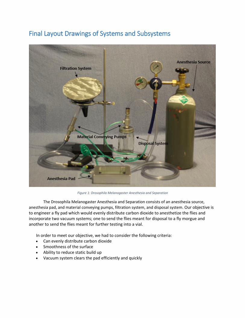
Figure 1: Drosophila Melanogaster Anesthesia and Separation
The Drosophila Melanogaster Anesthesia and Separation consists of an anesthesia source,
anesthesia pad, and material conveying pumps, filtration system, and disposal system. Our objective is to engineer a fly pad which would evenly distribute carbon dioxide to anesthetize the flies and incorporate two vacuum systems; one to send the flies meant for disposal to a fly morgue and another to send the flies meant for further testing into a vial.
In order to meet our objective, we had to consider the following criteria: Can evenly distribute carbon dioxide
Smoothness of the surface
Ability to reduce static build up
Vacuum system clears the pad efficiently and quickly
Fly Anesthesia Pad
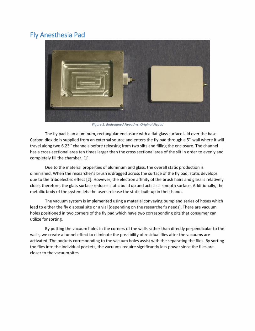
Figure 2: Redesigned Flypad vs. Original Flypad
The fly pad is an aluminum, rectangular enclosure with a flat glass surface laid over the base.
Carbon dioxide is supplied from an external source and enters the fly pad through a 5’’ wall where it will
travel along two 6.23’’ channels before releasing from two slits and filling the enclosure. The channel
has a cross-sectional area ten times larger than the cross sectional area of the slit in order to evenly and
completely fill the chamber. [1]
Due to the material properties of aluminum and glass, the overall static production is
diminished. When the researcher’s brush is dragged across the surface of the fly pad, static develops
due to the triboelectric effect [2]. However, the electron affinity of the brush hairs and glass is relatively
close, therefore, the glass surface reduces static build up and acts as a smooth surface. Additionally, the
metallic body of the system lets the users release the static built up in their hands.
The vacuum system is implemented using a material conveying pump and series of hoses which
lead to either the fly disposal site or a vial (depending on the researcher’s needs). There are vacuum
holes positioned in two corners of the fly pad which have two corresponding pits that consumer can
utilize for sorting.
By putting the vacuum holes in the corners of the walls rather than directly perpendicular to the
walls, we create a funnel effect to eliminate the possibility of residual flies after the vacuums are
activated. The pockets corresponding to the vacuum holes assist with the separating the flies. By sorting
the flies into the individual pockets, the vacuums require significantly less power since the flies are
closer to the vacuum sites.
Filtration and Disposal Systems
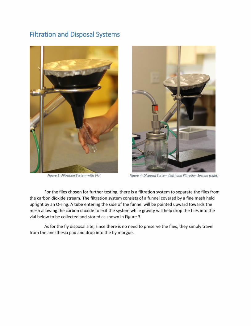
For the flies chosen for further testing, there is a filtration system to separate the flies from
the carbon dioxide stream. The filtration system consists of a funnel covered by a fine mesh held
upright by an O-ring. A tube entering the side of the funnel will be pointed upward towards the
mesh allowing the carbon dioxide to exit the system while gravity will help drop the flies into the
vial below to be collected and stored as shown in Figure 3.
As for the fly disposal site, since there is no need to preserve the flies, they simply travel
from the anesthesia pad and drop into the fly morgue.
Figure 3: Filtration System with Vial Figure 4: Disposal System (left) and Filtration System (right)
Final Bill of Materials
Summary Report Flypad Summary
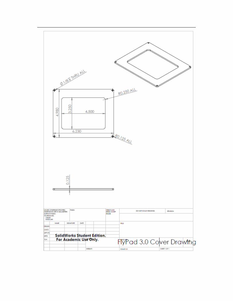
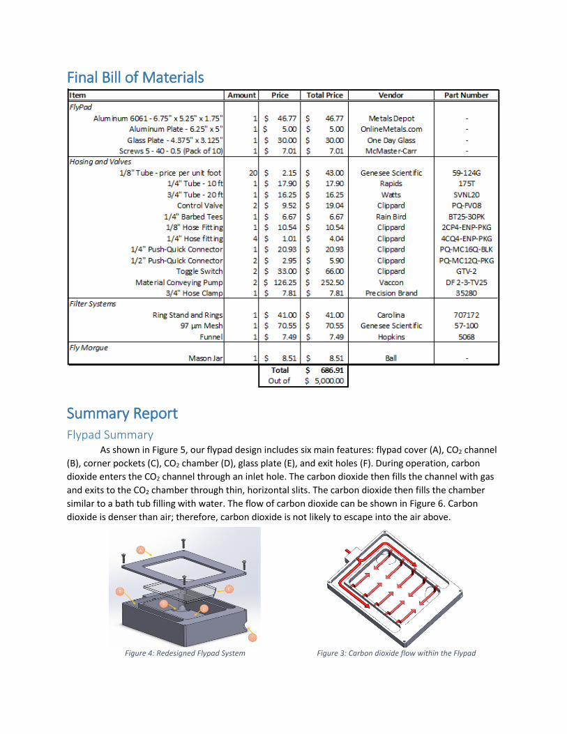
As shown in Figure 5, our flypad design includes six main features: flypad cover (A), CO2 channel
(B), corner pockets (C), CO2 chamber (D), glass plate (E), and exit holes (F). During operation, carbon
dioxide enters the CO2 channel through an inlet hole. The carbon dioxide then fills the channel with gas
and exits to the CO2 chamber through thin, horizontal slits. The carbon dioxide then fills the chamber
similar to a bath tub filling with water. The flow of carbon dioxide can be shown in Figure 6. Carbon
dioxide is denser than air; therefore, carbon dioxide is not likely to escape into the air above.
Figure 3: Carbon dioxide flow within the Flypad Figure 4: Redesigned Flypad System
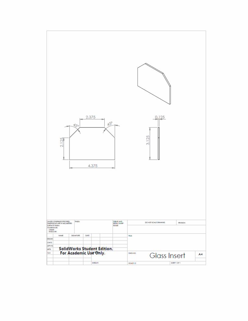
At the bottom of the chamber is the glass plate to provide researchers the smooth surface
needed to work on. Two corners of the chamber have pockets that are used to separate flies for either
storage or disposal. Flies are vacuumed out of the flypad through the exit holes via ¼” hosing which are
powered by the material conveying pump.
The idea of thin, long slits rather than many holes for the transfer of carbon dioxide from the
channel to the chamber, is a large benefit for the engineers building and assessing the system because it
is easier to manufacture and determine the cross-sectional area. Additionally, the glass piece is
beneficial because the surface is absolutely smooth and easy to clean by simple removal.
Due to the fillets in the corners of the chamber, however, the glass plate must have a smaller
area than the bottom surface of the chamber; therefore, there exists space for flies to fall between the
edge of the plate and the chamber wall. This can be resolved by shaping the glass to fit with the fillets,
increasing the total area of the plate. Another recommendation for redesign is to use an exit hose with a
larger inner diameter.
Most pieces of the flypad were made using the Bridgeport Milling Machines in the Engineering
Fabrication Laboratory. The outer shape was made using a shell end tool and an end mill tool. The inlet
hole was drilled and tapped to fit a ¼” NPT thread. The exit holes were then drilled using 45-45-90
triangles to make the diagonal pathways.
Next, the chamber, channel, pockets, and slits were milled using a CNC ESPRIT code. Finally, the
holes to attach the flypad cover to the main piece were drilled and tapped to fit 5-40-0.5 screws. Once
the main piece is manufactured, the cover can be made by milling out a hole of a metal plate, and the
holes in each corner can be drilled. The glass plate was ordered to specific dimensions, so no
manufacturing was required for this part.
All materials other than the glass plate, screws, and the hosing are made from 6061 Aluminum
Alloy. Metal was chosen to help eliminate static build up on the surface of the glass. The aluminum,
being conductive, can send static electricity to the user’s hand (a ground) and out of the system.
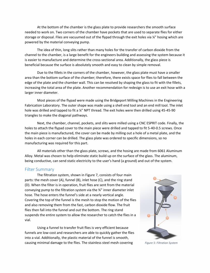
Filter Summary The filtration system, shown in Figure 7, consists of four main
parts: the mesh cover (A), funnel (B), inlet hose (C), and the ring stand
(D). When the filter is in operation, fruit flies are sent from the material
conveying pump to the filtration system via the ¾” inner diameter inlet
hose. The hose enters the funnel’s side at a nearly vertical angle.
Covering the top of the funnel is the mesh to stop the motion of the flies
and also removing them from the fast, carbon dioxide flow. The fruit
flies then fall into the funnel and out the bottom. The ring stand
suspends the entire system to allow the researcher to catch the flies in a
vial.
Using a funnel to transfer fruit flies is very efficient because
funnels are low-cost and researchers are able to quickly gather the flies
into a vial. Additionally, the plastic material of the funnel is smooth,
causing minimal damage to the flies. The stainless steel mesh covering Figure 5: Filtration System
the top opening has an aperture size of 97 microns. This mesh is normally used for fruit fly experiments,
so using the mesh is a good tool to separate the flies from the flowing carbon dioxide.
The whole system is relatively simple to set up considering all the pieces were purchased from
an outside source. A drill was used to make the hole in the side of the funnel for the inlet hose, and hot
glue was using to attach the steel mesh onto the top of the funnel. All other pieces were assembled
together without the use of tools.
In a re-design, the funnel may be larger to all distance for the flow of carbon dioxide and fruit
flies to reduce velocity, causing minimal damage when making contact with the steel mesh, or even
using a material conveying pump that creates a lower velocity flow. Additionally, a new design may
include creating a way to attach the mesh onto the funnel so that the mesh may be removed and
cleaned or replaced.
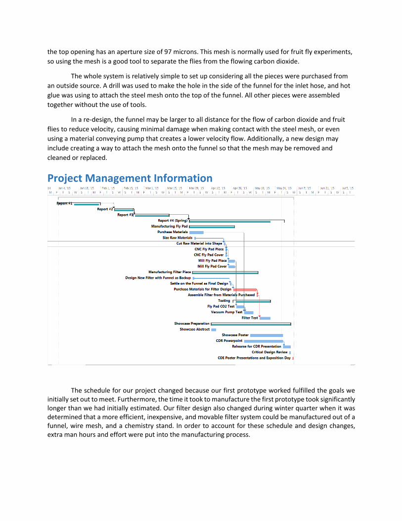
Project Management Information
The schedule for our project changed because our first prototype worked fulfilled the goals we initially set out to meet. Furthermore, the time it took to manufacture the first prototype took significantly longer than we had initially estimated. Our filter design also changed during winter quarter when it was determined that a more efficient, inexpensive, and movable filter system could be manufactured out of a funnel, wire mesh, and a chemistry stand. In order to account for these schedule and design changes, extra man hours and effort were put into the manufacturing process.
Bibliography 1. Sarigul-Klijn, M. Even Flow, [Office Hours Discussion], University of California Davis.
2. “Triboelectric Series.” The Triboelectric Series. Alphalabs Inc. Web. 16 Mar. 2015.
<http://www.trifield.com/content/tribo-electric-series/>
3. "DF Series Performance Chart." DF Series Performance Chart. Web. 16 Mar. 2015.
<http://www.vaccon.com/perf-df.aspx>.
Appendix Design Analysis
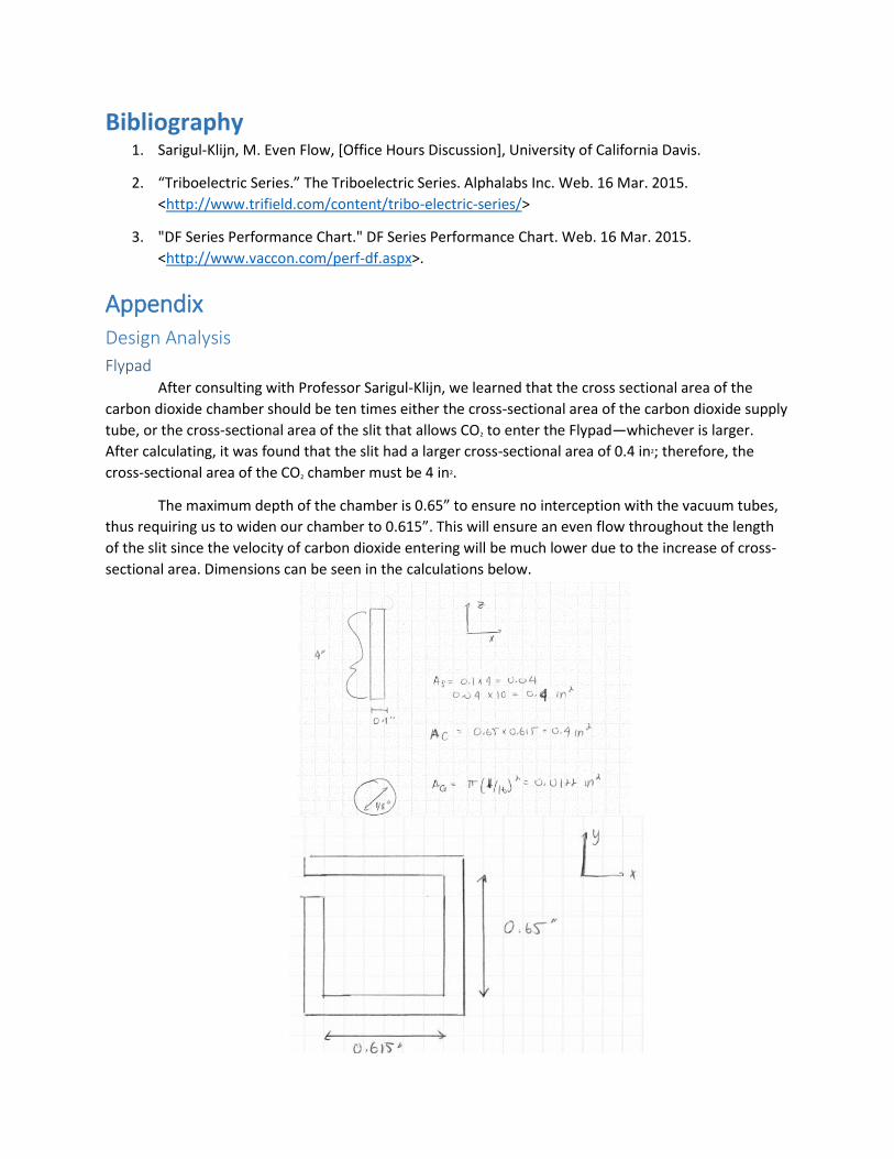
Flypad After consulting with Professor Sarigul-Klijn, we learned that the cross sectional area of the
carbon dioxide chamber should be ten times either the cross-sectional area of the carbon dioxide supply
tube, or the cross-sectional area of the slit that allows CO2 to enter the Flypad—whichever is larger.
After calculating, it was found that the slit had a larger cross-sectional area of 0.4 in2; therefore, the
cross-sectional area of the CO2 chamber must be 4 in2.
The maximum depth of the chamber is 0.65” to ensure no interception with the vacuum tubes,
thus requiring us to widen our chamber to 0.615”. This will ensure an even flow throughout the length
of the slit since the velocity of carbon dioxide entering will be much lower due to the increase of cross-
sectional area. Dimensions can be seen in the calculations below.
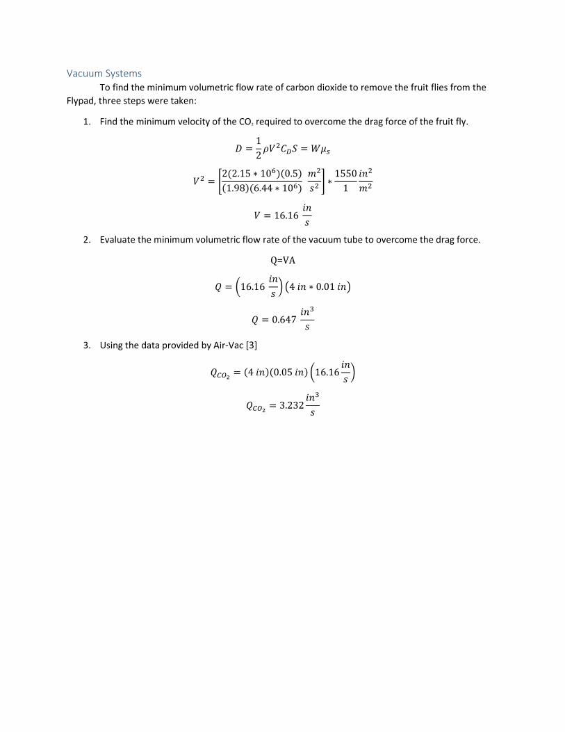
Vacuum Systems To find the minimum volumetric flow rate of carbon dioxide to remove the fruit flies from the
Flypad, three steps were taken:
1. Find the minimum velocity of the CO2 required to overcome the drag force of the fruit fly.
𝐷 =1
2𝜌𝑉2𝐶𝐷𝑆 = 𝑊𝜇𝑠
𝑉2 = [2(2.15 ∗ 106)(0.5)
(1.98)(6.44 ∗ 106) 𝑚2
𝑠2] ∗
1550
1
𝑖𝑛2
𝑚2
𝑉 = 16.16 𝑖𝑛
𝑠
2. Evaluate the minimum volumetric flow rate of the vacuum tube to overcome the drag force.
Q=VA
𝑄 = (16.16 𝑖𝑛
𝑠) (4 𝑖𝑛 ∗ 0.01 𝑖𝑛)
𝑄 = 0.647 𝑖𝑛3
𝑠
3. Using the data provided by Air-Vac [3]
𝑄𝐶𝑂2= (4 𝑖𝑛)(0.05 𝑖𝑛) (16.16
𝑖𝑛
𝑠)
𝑄𝐶𝑂2= 3.232
𝑖𝑛3
𝑠
User Manual Contents: This document explains how to use the fly anesthesia system. Refer to the following categories:
I. Supplies A. Filter System B. Fly Morgue
II. Setup III. Instructions IV. Maintenance and Repair V. Replacement Parts
I. Supplies:
The fly anesthesia system includes the following
subsystems and their respective materials:
A. Fly Anesthesia System
1. Materials
a. Carbon dioxide tank
b. Flypad frame
c. Flypad cover
d. Glass plate
2. Connection Pieces
a. 5-40-0.5 screws (4)
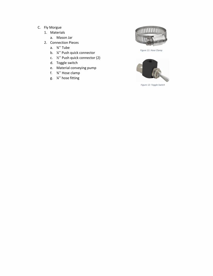
b. ¼” Hose fitting
c. ¼’’ Tube
d. ¾’’ Tube
e. ¼’’ Hose fitting
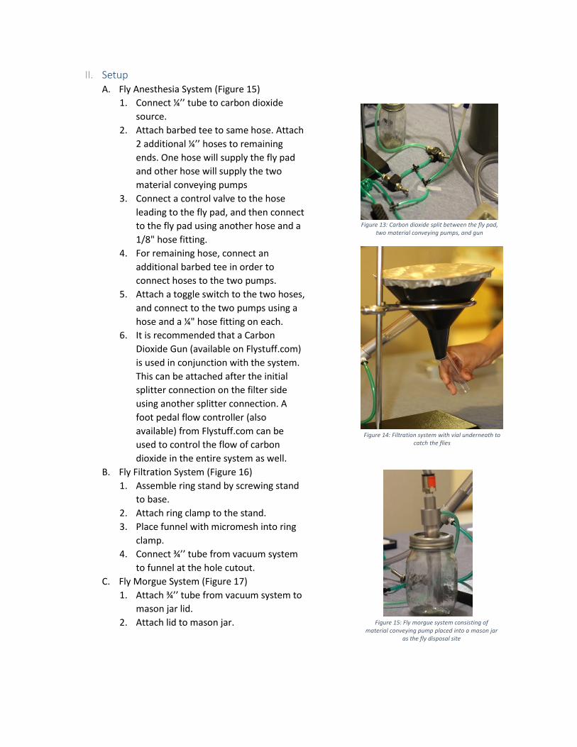
f. ¼’’ Barbed tee
B. Filter System
1. Materials
a. Ring Stand
b. Ring Clamp
c. 5’’ Funnel
d. 97 micron mesh
2. Connection Pieces
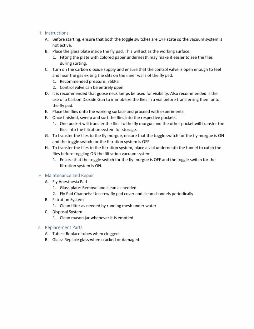
a. ¼’’ Push quick connector
b. ½’’ Push quick connector (2)
c. Toggle switch
d. Control valve
e. ¼’’ Tube
f. ¾’’ Tube
g. ¾’’ Hose clamp
h. ¼’’ hose fitting
i. 1/8’’ Hose fitting
Figure 6: 5-40-0.5 Screw
Figure 7: Hose Fitting
Figure 8: Barbed Tee
Figure 9: Push Quick Connector
Figure 10: Control Valve
C. Fly Morgue
1. Materials
a. Mason Jar
2. Connection Pieces
a. ¾’’ Tube
b. ¼’’ Push quick connector
c. ½’’ Push quick connector (2)
d. Toggle switch
e. Material conveying pump
f. ¾’’ Hose clamp
g. ¼’’ hose fitting
Figure 12: Toggle Switch
Figure 11: Hose Clamp
II. Setup A. Fly Anesthesia System (Figure 15)
1. Connect ¼’’ tube to carbon dioxide
source.
2. Attach barbed tee to same hose. Attach
2 additional ¼’’ hoses to remaining
ends. One hose will supply the fly pad
and other hose will supply the two
material conveying pumps
3. Connect a control valve to the hose
leading to the fly pad, and then connect
to the fly pad using another hose and a
1/8" hose fitting.
4. For remaining hose, connect an
additional barbed tee in order to
connect hoses to the two pumps.
5. Attach a toggle switch to the two hoses,
and connect to the two pumps using a
hose and a ¼" hose fitting on each.
6. It is recommended that a Carbon
Dioxide Gun (available on Flystuff.com)
is used in conjunction with the system.
This can be attached after the initial
splitter connection on the filter side
using another splitter connection. A
foot pedal flow controller (also
available) from Flystuff.com can be
used to control the flow of carbon
dioxide in the entire system as well.
B. Fly Filtration System (Figure 16)
1. Assemble ring stand by screwing stand
to base.
2. Attach ring clamp to the stand.
3. Place funnel with micromesh into ring
clamp.
4. Connect ¾’’ tube from vacuum system
to funnel at the hole cutout.
C. Fly Morgue System (Figure 17)
1. Attach ¾’’ tube from vacuum system to
mason jar lid.
2. Attach lid to mason jar.
Figure 13: Carbon dioxide split between the fly pad, two material conveying pumps, and gun
Figure 14: Filtration system with vial underneath to catch the flies
Figure 15: Fly morgue system consisting of material conveying pump placed into a mason jar
as the fly disposal site
III. Instructions A. Before starting, ensure that both the toggle switches are OFF state so the vacuum system is
not active.
B. Place the glass plate inside the fly pad. This will act as the working surface.
1. Fitting the plate with colored paper underneath may make it easier to see the flies
during sorting.
C. Turn on the carbon dioxide supply and ensure that the control valve is open enough to feel
and hear the gas exiting the slits on the inner walls of the fly pad.
1. Recommended pressure: 75kPa
2. Control valve can be entirely open.
D. It is recommended that goose neck lamps be used for visibility. Also recommended is the
use of a Carbon Dioxide Gun to immobilize the flies in a vial before transferring them onto
the fly pad.
E. Place the flies onto the working surface and proceed with experiments.
F. Once finished, sweep and sort the flies into the respective pockets.
1. One pocket will transfer the flies to the fly morgue and the other pocket will transfer the
flies into the filtration system for storage.
G. To transfer the flies to the fly morgue, ensure that the toggle switch for the fly morgue is ON
and the toggle switch for the filtration system is OFF.
H. To transfer the flies to the filtration system, place a vial underneath the funnel to catch the
flies before toggling ON the filtration vacuum system.
1. Ensure that the toggle switch for the fly morgue is OFF and the toggle switch for the
filtration system is ON.
IV. Maintenance and Repair A. Fly Anesthesia Pad
1. Glass plate: Remove and clean as needed
2. Fly Pad Channels: Unscrew fly pad cover and clean channels periodically
B. Filtration System
1. Clean filter as needed by running mesh under water
C. Disposal System
1. Clean mason jar whenever it is emptied
V. Replacement Parts A. Tubes: Replace tubes when clogged.
B. Glass: Replace glass when cracked or damaged
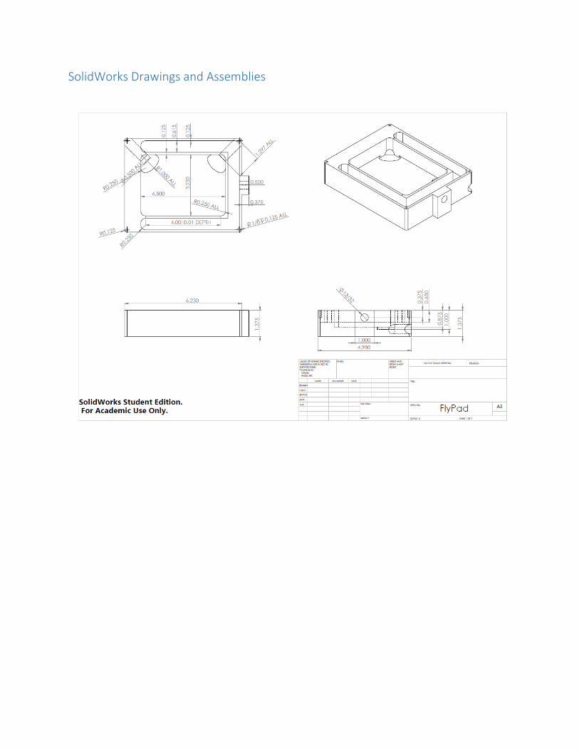
SolidWorks Drawings and Assemblies